Embed Size (px)
Citation preview
ISBN 978-80-261-0973-0, © University of West Bohemia, 2021
Current Harmonic Analysis for AC Traction Substation with Power Balancer
Vojtech Blahnik Research and Innovation Centre for
Electrical Engineering University of West Bohemia
Pilsen, Czech Republic [email protected]
Milos Straka Research and Innovation Centre for
Electrical Engineering University of West Bohemia
Pilsen, Czech Republic [email protected]
Martin Pittermann Department of Power Electronics and
Machines University of West Bohemia
Pilsen, Czech Republic [email protected]
Abstract — This paper describes results of the harmonic
analysis of currents harmonic analysis performed for an
advanced AC traction Substation. AC traction substation
feeding 25 kV / 50 Hz traction catenary and provide power
symmetrization by semiconductor device called electronic
balancer. The analysis is concern to currents of electronic
balancer part of substation and the grid currents corresponding
with quality of taken energy. The harmonic currents
components are evaluate with the respect to the switching
frequency of IGBTs (250 Hz), modulation technique (PS-PWM)
and dead time duration (10 µs). The results are evaluated on the
created model of the AC traction substation with multilevel
converter topology, having the nominal power of 12.5 MVA.
Keywords— traction substation; power balancer; harmonic
analysis, grid current quality
I. INTRODUCTION
The promising topology of the AC traction substation was introduced in [1]. This TSS (Traction SubStation) is especially designed for using in the Czech Republic (single phase 25 kV / 50 Hz) where is assumed feed from a distribution power grid. In Europe is often preferred a SFC (Static Frequency Converter) topology, without neutral section (dead zone). However, the complex system brigs disadvantages, such as lower reliability and a high purchase price. Partial symmetrization is done by delta connection in own. However, fully symmetrization for different state of load of traction railway is available only with additional power balancer. Nowadays it is able to use electronic balancer with semiconductor device based on IGBT technology, as popular industrial solution.
II. TRACTION SUBSTATION WITH ELECTRONIC BALANCER
The introduced topology with electronic balancer shows Fig. 1, which provides full power symmetrization, based on CHB (Cascade H-Bridge) topology. This semiconductors converter topology can be seen as a STATCOM converter or power active filter. Due to it is important to focus on distortion of distribution power grid especially on contain of higher order current harmonics. The power circuit of CHB consists of serial connected power cells (H-Bridges). Each cell contains H-Bridge (HB) converters with separated DC-link. The important indicator is content of current harmonic, especially harmonic lower then 2500 Hz. This paper follows the paper [2] and [3], where was solved the origin of harmonics in terms of modulation. With focus on a single-phase HB and extending to the CHB topology. However, this paper evaluate the important fact called the dead time influence [4], [5], because in this case is necessary to used longer duration of dead time (10 µs), than is commonly used.
Fig. 1. Power circuit of AC traction substation with electronic balancer
based on multilevel CHB topology
The CHB topology is suitable for use at medium voltage level and the most used modulation is Phase Shifted PWM (PS-PWM).
The details of modulation signals under PS-PWM (for positive 10 ms long half period) are shown in Fig. 2 The whole one period of multilevel voltage waveform of CHB converter, is show in Fig. 3. This waveform acquires 25 of voltage levels.
Fig. 2. The example of signals for one-phase of multilevel topology using
PS-PWM techique (12 x saw signals 2 x control signals, during 10 ms long half period)
2021
Inte
rnat
iona
l Con
fere
nce
on A
pplie
d El
ectr
onic
s (AE
) | 9
78-8
0-26
1-09
73-0
/21/
$31.
00 ©
2021
10.2
3919
/AE5
1540
.202
1.95
4290
8
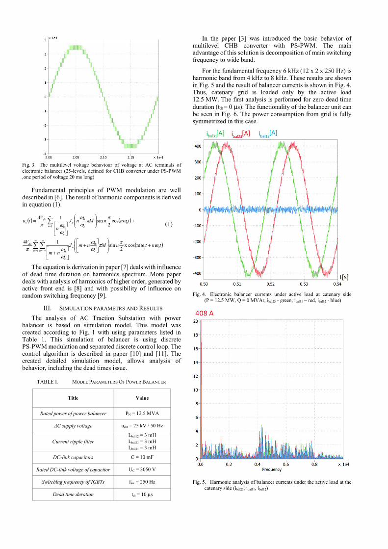
Fig. 3. The multilevel voltage behaviour of voltage at AC terminals of electronic balancer (25-levels, defined for CHB converter under PS-PWM ,one period of voltage 20 ms long)
Fundamental principles of PWM modulation are well described in [6]. The result of harmonic components is derived in equation (1).
( ) ( )
( )tntnMnmJ
nm
V
tnnMnJ
n
Vtu
c
n
m n
c
dc
n c
n
c
dcv
0c0
1 0
10
0
0
mcos x 2
sin14
cos2
sin14
ωωπ
πω
ω
ω
ωπ
ωπ
πω
ω
ω
ωπ
+
+
+
+
=
∞
=
∞
−∞=
∞
= (1)
The equation is derivation in paper [7] deals with influence of dead time duration on harmonics spectrum. More paper deals with analysis of harmonics of higher order, generated by active front end is [8] and with possibility of influence on random switching frequency [9].
III. SIMULATION PARAMETRS AND RESULTS
The analysis of AC Traction Substation with power balancer is based on simulation model. This model was created according to Fig. 1 with using parameters listed in Table 1. This simulation of balancer is using discrete PS-PWM modulation and separated discrete control loop. The control algorithm is described in paper [10] and [11]. The created detailed simulation model, allows analysis of behavior, including the dead times issue.
TABLE I. MODEL PARAMETERS OF POWER BALANCER
Title Value
Rated power of power balancer PN = 12.5 MVA
AC supply voltage ucat = 25 kV / 50 Hz
Current ripple filter
Lbal12 = 3 mH Lbal23 = 3 mH Lbal31 = 3 mH
DC-link capacitors C = 10 mF
Rated DC-link voltage of capacitor UC = 3050 V
Switching frequency of IGBTs fsw = 250 Hz
Dead time duration tdt = 10 µs
In the paper [3] was introduced the basic behavior of multilevel CHB converter with PS-PWM. The main advantage of this solution is decomposition of main switching frequency to wide band.
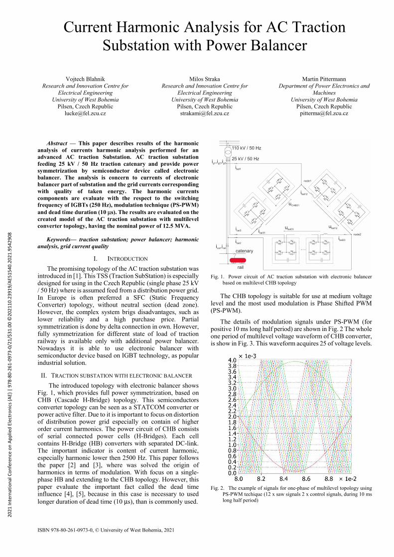
For the fundamental frequency 6 kHz (12 x 2 x 250 Hz) is harmonic band from 4 kHz to 8 kHz. These results are shown in Fig. 5 and the result of balancer currents is shown in Fig. 4. Thus, catenary grid is loaded only by the active load 12.5 MW. The first analysis is performed for zero dead time duration (tdt = 0 µs). The functionality of the balancer unit can be seen in Fig. 6. The power consumption from grid is fully symmetrized in this case.
Fig. 4. Electronic balancer currents under active load at catenary side
(P = 12.5 MW, Q = 0 MVAr, ibal23 - green, ibal31 – red, ibal12 - blue)
Fig. 5. Harmonic analysis of balancer currents under the active load at the catenary side (ibal23, ibal31, ibal12)
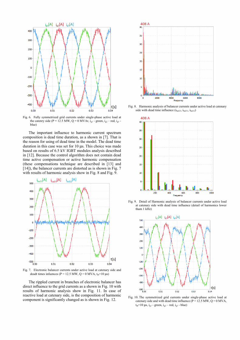
Fig. 6. Fully symmetrized grid currents under single-phase active load at
the catenry side (P = 12.5 MW, Q = 0 MVAr, ig1 - green, ig2 – red, ig3 - blue)
The important influence to harmonic current spectrum composition is dead time duration, as a shown in [7]. That is the reason for using of dead time in the model. The dead time duration in this case was set for 10 µs. This choice was made based on results of 6.5 kV IGBT modules analysis described in [12]. Because the control algorithm does not contain dead time active compensation or active harmonic compensation (these compensations technique are described in [13] and [14]), the balancer currents are distorted as is shown in Fig. 7 with results of harmonic analysis show in Fig. 8 and Fig. 9.
Fig. 7. Electronic balancer currents under active load at catenary side and
deadt times infuences (P = 12.5 MW, Q = 0 MVA, tdt=10 µs)
The rippled current in branches of electronic balancer has direct influence to the grid currents as a shown in Fig. 10 with results of harmonic analysis show in Fig. 11. In case of reactive load at catenary side, is the composition of harmonic component is significantly changed as is shown in Fig. 12.
Fig. 8. Harmonic analysis of balancer currents under active load at catenary
side with dead time influence (ibal23, ibal31, ibal12)
Fig. 9. Detail of Harmonic analysis of balancer currents under active load
at catenary side with dead time influence (detail of harmonics lower tham 1 kHz)
Fig. 10. The symmetrized grid currents under single-phase active load at
catenary side and with dead time influence (P = 12.5 MW, Q = 0 MVA, tdt=10 µs, ig1 - green, ig2 – red, ig3 - blue)
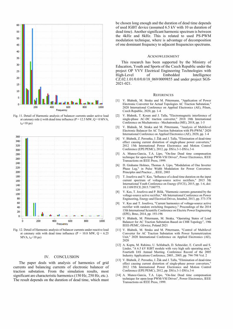
Fig. 11. Detail of Harmonic analysis of balancer currents under active load
at catenary side () with dead time influence (P = 12.5 MW, Q = 0 MVA, tdt=10 µs)
Fig. 12. Detail of Harmonic analysis of balancer currents under reactive load
at catenary side with dead time influence (P = 10.8 MW, Q = 6.25 MVA, tdt=10 µs)
IV. CONCLUSION
The paper deals with analysis of harmonics of grid currents and balancing currents of electronic balancer of traction substation. From the simulation results, most significant are characteristic harmonics (150 Hz, 250 Hz, etc.). The result depends on the duration of dead time, which must
be chosen long enough and the duration of dead time depends of used IGBT device (assumed 6.5 kV with 10 us duration of dead time). Another significant harmonic spectrum is between the 4kHz and 8kHz. This is related to used PS-PWM modulation technique, where is advantage of decomposition of one dominant frequency to adjacent frequencies spectrums.
ACKNOWLEDGMENT
This research has been supported by the Ministry of Education, Youth and Sports of the Czech Republic under the project OP VVV Electrical Engineering Technologies with High-Level of Embedded Intelligence CZ.02.1.01/0.0/0.0/18_069/0009855 and under project SGS-2021-021.
REFERENCES
[1] V. Blahnik, M. Straka and M. Pittermann, "Application of Power Electronic Converter for Actual Topologies AC Traction Substation," 2020 International Conference on Applied Electronics (AE), Pilsen, Czech Republic, 2020, pp. 1-4
[2] V. Blahnik, T. Kosan and J. Talla, "Electromagnetic interference of single-phase AC-DC traction converter," 2018 18th International Conference on Mechatronics - Mechatronika (ME), 2018, pp. 1-5
[3] V. Blahnik, M. Straka and M. Pittermann, "Analysis of Multilevel Electronic Balancer for AC Traction Substation with PS-PWM," 2020 International Conference on Applied Electronics (AE), 2020, pp. 1-4
[4] V. Blahník, Z. Peroutka, J. Žák and J. Talla, "Elimination of dead-time effect causing current distortion of single-phase power converters," 2012 15th International Power Electronics and Motion Control Conference (EPE/PEMC), 2012, pp. DS1e.3-1-DS1e.3-6
[5] A. Munoz-Garcia, T.A. Lipo, "On-line Dead time compensation technique for open-loop PWM-VSI Drives", Power Electronics, IEEE Transactions on IEEE Press, 1999.
[6] D. Grahame Holmes, Thomas A. Lipo, "Modulation of One Inverter Phase Leg," in Pulse Width Modulation for Power Converters: Principles and Practice , , IEEE, 2003
[7] T. Josefova and V. Kus, "Influence of a dead time duration on the input current spectrum of voltage-source active rectifiers," 2015 5th International Youth Conference on Energy (IYCE), 2015, pp. 1-6, doi: 10.1109/IYCE.2015.7180775.
[8] V. Kus, T. Josefova and P. Bilik, "Harmonic currents generated by the voltage-source active rectifier," 4th International Conference on Power Engineering, Energy and Electrical Drives, Istanbul, 2013, pp. 373-378
[9] V. Kus and T. Josefova, "Current harmonics of voltage-source active rectifier with random switching frequency," Proceedings of the 2014 15th International Scientific Conference on Electric Power Engineering (EPE), Brno, 2014, pp. 193-196
[10] V. Blahnik, M. Pittermann, M. Straka, “Operating States of Load Balancer for AC Traction Substation Based on CHB Topology”, 19th IEEE-PEMC, Gliwice, Poland 2021
[11] V. Blahnik, M. Straka and M. Pittermann, "Control of Multilevel Converter for AC Traction Substation with Power Symmetrization Unit," 2020 International Conference on Applied Electronics (AE), 2020
[12] A. Kopta, M. Rahimo, U. Schlabach, D. Schneider, E. Carroll and S. Linder, "A 6.5 kV IGBT module with very high safe operating area," Fourtieth IAS Annual Meeting. Conference Record of the 2005 Industry Applications Conference, 2005., 2005, pp. 794-798 Vol. 2
[13] V. Blahník, Z. Peroutka, J. Žák and J. Talla, "Elimination of dead-time effect causing current distortion of single-phase power converters," 2012 15th International Power Electronics and Motion Control Conference (EPE/PEMC), 2012, pp. DS1e.3-1-DS1e.3-6
[14] A. Munoz-Garcia, T.A. Lipo, "On-line Dead time compensation technique for open-loop PWM-VSI Drives", Power Electronics, IEEE Transactions on IEEE Press, 1999.