Embed Size (px)
Citation preview

Current Slope Measurement Strategies for Sensorless
Control of a Three Phase Radial Active Magnetic Bearing
Matthias Hofer, Thomas Nenning, Markus Hutterer, and Manfred Schrodl
Institute of Energy Systems and Electric DrivesVienna University of Technology,
Gusshausstraße 25, 1040 Vienna, [email protected]
Abstract
This paper discusses the sensorless control of a three phase radial active magnetic bearing (AMB).
Self-sensing or sensorless methods mean, that the electromagnetic actuator itself is used as position sen-
sor too and the rotor position information is evaluated by electrical quantities as currents and voltages.
Thus, external rotor position sensors can be omitted and allow a simplification of magnetic bearing
system architectures. Since many years [7, 11] sensorless AMBs are field of research to reach perfor-
mance parameters as bearing systems with position sensor do have. The proposed self-sensing method
is based on inductance measurement by current slope detection during voltage pulse injection or inte-
grated in the Pulse Width Modulation (PWM) pattern applied to three phase radial AMBs. Different
electrical current slope measurement strategies are investigated regarding self-sensing performance and
accuracy. Two different three phase AMB prototype setups are explained and used for experiments.
The measurement results show improvements by different current slope detection strategies. Finally
some examples of the behavior during sensorless levitation in a closed loop position control represent
the potential of self-sensing three phase AMBs to industrial applications.
1 Introduction
Classic setups of AMB applications are complex systems consisting modules as the axial andradial AMBs, the rotor position sensors and appropriate measurement amplifiers, the AMBpower amplifiers, the control electronics, the electric machine and the motor drive inverter.Especially the sensor systems represent a high cost portion of the AMB system, because theyare expensive and for a 5 axis stabilization such units have to be multiple used. Thus, dealingwith a sensorless algorithm instead of a sensor unit will reduce product costs significantly bya high utilization of already used components. Another potential for product cost reductionis identified in the AMB power amplifiers. Depending on the bearing architecture usuallyH-brigde topologies are used for at least each single axis. Supplying two axis of one radialAMB from one three phase inverter allows a reduction of power semiconductors and currentsensors. Today, three phase inverters have reached a high grade of modularity from a low upto a high power range, are well industrialized and produced in a huge amount for industrialdrive applications. These two topics are the motivation for research on sensorless three phaseAMBs. Reaching required system performance with this approach is a possible way to enlargethe field of additional industrial applications of AMB.
Since several years self-sensing approaches are field of research according to [7,11]. Estima-tion based methods using the current information alone and methods using the current rippleinformation by high frequency excitation or voltage injection are known. In the last time thefocus is given on current slope based methods, as in [5, 8]. In these works current slope basedself-sensing approaches are applied to a single axis setup or to a classical 4 respectively 8 pole
1

AMB topology. The known limitation factors for self-sensing performance are identified withinsaturation [7] and eddy currents [2, 7]. Avoidance of saturation can be reached by an appro-priate material utilization in the AMB design focused on linearity. The second topic, the eddycurrent effects related to self-sensing, is also part of this article. By the presented measurementresults limitations caused by eddy currents are figured out. One way for a significant reductionis finally found by the introduction of a differential approach. This concept overcomes thegeneral downside of eddy current and brings the self-sensing accuracy close to the performanceknown from AMB systems with position sensors. This can be seen by the new results relatedto the sensorless position detection accuracy in an open loop and and the behavior in a closedloop sensorless position control.
1.1 Three Phase Active Magnetic Bearings
The minimum number of stator poles for radial active magnetic bearings was investigated in [6]and results in a number of three stator poles. In this article the focus is given to three phasehybrid magnetic bearings (HMBs). HMBs use permanent magnet biasing for an AMB and isknown for three phases as shown in [12]. The advantage is a reduction of the electric currentconsumption which was already evaluated in [3, 12]. The combination of permanent magnetflux and control flux is realized as shown in Fig. 1. In this way a homopolar flux distribution onthe rotor is given which lowers the iron loss at high rotational speeds compared to heteropolarbearings. Three phase AMBs can also be supplied by three H-bridges if the three coils are not
Figure 1: Three phase radial AMB with permanent magnet biasing
connected to each other. In this work the coils are connected to a star point and the threephases are supplied from a three phase voltage source inverter according to Fig. 2.
The implementation of a three phase structure is also possible using a higher number of statorpoles. The second bearing prototype investigated in this work consists of 6 poles connected tothree phases as shown in Fig. 3. Here two poles opposite each other are equipped with excitationcoils in a way, that on one side the total flux is increased and on the other side the total fluxis decreased, see Fig. 4. Thus, the resulting electromagnetic forces on the opposite poles arenot compensating each other, but react in same direction. In this topology the superposition

Figure 2: Three phase inverter applied to a three phase radial AMB.
Figure 3: Coil connection of the threephase AMB with 6 poles for the usage of athree phase inverter.
Figure 4: Three phase AMB with 6 poles.
of the control flux and the bias flux also lead to a hompolar bearing and the advantages of athree phase inverter are still used.
1.2 Sensorless Rotor Position Detection
The sensorless control approach used in this work is based on the so called INFORM (IndirectFlux detection by Online Reactance Measuremnt) method which is known from sensorlesscontrol of electrical drive applications. The basic idea uses an inductance variation whichis evaluated during voltage injection pulses and current slope measurements. At AMBs thismethod allows the rotor position determination, because the AMB stator inductances are notconstant and depend mainly on the radial rotor displacement. Modeling the three stator coilinductances of the AMB according to Fig. 1 in a perpendicular coordinate system (x, y) andconsidering the behavior in x-direction the inverse of the rated self inductance lXX for idealpermeable iron yields
1
lXX |y=0=
L0
LXX= 1− x
2δ0(1)

Here L0 is the nominal inductance and δ0 nominal airgap at centered rotor. This equationshow a linear dependency on the rotor displacement x which is determined by measurement ofcurrent slopes during voltage pulses [4].
Consindering the inductance behavior of the 6 pole AMB according to Fig. 3 and Fig. 4it can be easily seen, that by a rotor displacement in x-direction the airgap at the coil U+decreases as at in the opposite coil U- the airgap increases. Modeling the rated inductances ofboth systems for ideal permeable iron result in
1lUU+|y=0
= L0
LUU+= 1− x
2δ01
lUU−|y=0= L0
LUU−= 1 + x
2δ0
(2)
Herein can be seen that a serial connection of the two opposite coils would cancel the inductancedependency on the rotor position. Therefore to achieve a high dependency on the rotor positionthe two three phase systems (U+V+W+ and U-V-W-) are connected parallel. Using this threephase AMB architecture the simple current slope evaluation of the classical three phase AMBwith three poles is not possible any more, because the currents and the current slopes of thecoil U+ and U+ containing the rotor position information are part of the phase current iU .More details how the current slopes are evaluated are shown in the next sections.
1.3 Pulse Width Modulation
Today in most electric drive applications equipped with three phase voltage source inverters asymmetric Pulse Width Modulation (PWM) utilizing six inverter switching states is used. ThisPWM current control was also used in the first investigations on self-sensing three phase AMBs[4] and current slope detection was implemented as real voltage injection pulses interruptingthis PWM pattern. In previous works [3, 9] the three active PWM method was proposed andalso implemented for self-sensing AMBs. The three active PWM concept uses only three of sixvoltage space phasors according to Fig. 5. Considering the achievable maximum space phasormagnitude without over-modulation at the three active PWM a limit is given at |uS | = 1/3uDC(inner circle of the triangle) and the symmetric PWM is limited at |uS | = 1/
√3 uDC (inner
circle of the hexagon). Although the voltage utilization is different the big advantage of thethree active PWM is, that the three active injection pulse sequence [3] is already includedand an additional interruption of the PWM pattern is not required any more. This leadsto the highest possible bandwidth for sensorless rotor position detection, because at everyPWM cycle the rotor position is calculated. Using injection pulses the applied injection ratedetermines the maximum sensing bandwidth. On the other hand this integrated sensorless rotorposition detection method into the three active PWM pattern can require a minimum pulsewidth depending on the method of current slopes measurement. This would further reduce theapplicable voltage space phasor magnitude |uS | and has to be considered in the self-sensingAMB system design.
2 Current Slope Detection
For evaluation of the current slopes several methods are known from literature. In this work thefocus is set on principles which are able to fulfill the requirements of high position sensing ac-curacy combined with low costs and a simple integration considering possible serial productionof industrial AMB applications. Therefore current slope sensing principles not fulfilling thesedemands, e.g. Rogowski coils, current clamps are not considered. In this work three different

Figure 5: Voltage space phasors and operation limits (circles) in classical PWM and three activeusing only three positive switching states.
methods are evaluated. First using the current signal itself an calculating the slope out of thecurrent by a ∆i/∆t approximation. Second for differential AMB setups a differential trans-former setup is used either for differential current measurement or for direct slope detection byan open loop differential transformer. In the following section these principles are explainedand evaluated for self-sensing performance of three phase AMBs.
2.1 Current Sampling Method
Nowadays digital signal processors (DSPs) are common in three phase electric drive invertersand consist of an on-board analog to digital converter (ADC) for time discrete sampling of theanalog current signals. A three phase inverter topology with a simple shunt resistor currentmeasurement principle is presented in Fig. 2
Additionally to the information of the current level, the same architecture can be used fordetection of the current slope at applied voltages. An example for detection of the current slopeby at least two sampling points is shown in Fig. 6. Here, two alternating voltage pulses areapplied and the current gradient is detected at both, during the rising and falling slope whichincrease measurement accuracy and eliminate influences of induced voltages and ohmic voltagedrops. In this example of a current slope the influence of eddy current effects can be seen veryclear. Immediately after each voltage switching the current slope is disturbed and it takes acertain time after the eddy currents are decayed. Thus the possible measurement range forthe current slope is reduced significantly (black line). Introducing additional sample values ofthe current signal as shown in [10], e.g. based on the mean difference method from outside toinside, result in an improvement of the position noise and also used in this work.
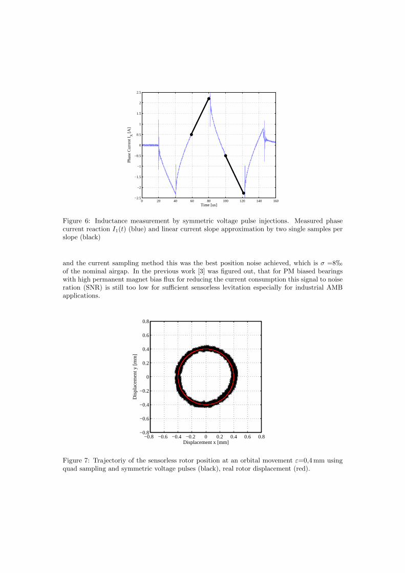
The position signal trajectory at orbital movement of a three phase AMB with currentslope measurement by shunt resistors is shown in Fig. 7. For a stationary rotor position astatistic evaluation show a standard deviation of σ=15µm at a nominal airgap of δ0 =1 mm.According to [3] by utilization of a three active injection pulse sequence with 16x oversamplingthe position noise was reduced to σ =8µm. Finally, with the three phase AMB prototype
0 20 40 60 80 100 120 140 160−2.5
−2
−1.5
−1
−0.5
0
0.5
1
1.5
2
2.5
Pha
se C
urre
nt I X [A
]
Time [us]
Figure 6: Inductance measurement by symmetric voltage pulse injections. Measured phasecurrent reaction I1(t) (blue) and linear current slope approximation by two single samples perslope (black)
and the current sampling method this was the best position noise achieved, which is σ =8hof the nominal airgap. In the previous work [3] was figured out, that for PM biased bearingswith high permanent magnet bias flux for reducing the current consumption this signal to noiseration (SNR) is still too low for sufficient sensorless levitation especially for industrial AMBapplications.
−0.8 −0.6 −0.4 −0.2 0 0.2 0.4 0.6 0.8−0.8
−0.6
−0.4
−0.2
0
0.2
0.4
0.6
0.8
Displacement x [mm]
Dis
plac
emen
t y [m
m]
Figure 7: Trajectoriy of the sensorless rotor position at an orbital movement ε=0,4 mm usingquad sampling and symmetric voltage pulses (black), real rotor displacement (red).

2.2 Current Slope Measurement by a Differential Transformer
For evaluation of the current slopes at a three phase AMB architecture with 6 poles the threephase inverter topology is slightly extended. Additionally a differential transformer is used tosum up the current slopes e.g. diU+/dt and diU−/dt of the opposite coils. By this conceptthe current values iU+ and iU− are canceled, which allows the usage of a small and simpletransformer, because only the different current slopes define the magnetic operation point ofthe transformer an not the absolute current levels. The current slope detection principle withthe differential transformer is depicted in Fig. 8. The primary coils given by only one turnand the number of turns of the secondary part is adjusted to the signal measurement range.Implementing a low resistance at the transformer output causes, that the measured voltageuINF is proportional to the secondary current ∆i of the transformer. Hence, this voltage uINFis evaluated by a separate ADC-input of the controller. A measurement example of the AMBprototype with a nominal airgap δ0=0,8 mm for two rotor positions is presented in Fig. 9. Thefigure shows on the left side the coil current iU+ and the measurement signal at a negativedisplacement in x-direction. By the differential approach the output signal has negative slopealthough the current slope diU+/dt is positive. On the right side the results are depicted forpositive displacement in x-direction. With this approach the full ADC operation range is usedfor current slope detection independently from the current signal iU .
Figure 8: Differential current slope measurement principle.
The rotor position signal at an orbital movement is presented in Fig. 10. At a radial dis-placement of ε=0,5 mm can be seen that the sensorless rotor position (black) differs slightlyfrom real position (red) in the circular shape. The root cause for this is given by the mechanicaltolerances of the prototype, especially as the touchdown bearings define the maximum eccen-tricity. The rotor position noise is much improved compared to the current sampling method.The statistical evaluation of a mechanical fixed rotor position show a distribution according toFig. 11. The standard deviation is σ =0,78µm which is only σ =0,98h of the nominal airgap.This is a big noise improvement nearly by a factor of 10 compared to σ =8h at the currentsampling method.
From the time signals in Fig. 9 can be seen, that the eddy currents influence the coil currentiU+ immediately after each switching of the inverter, but on the transformer output signal, thisinfluence is much smaller. Therefore the utilization of the current slope signal is higher than atthe current sampling principle.

Figure 9: Time signals of the phase current iU+ and the differential current ∆i in U -directionat two different rotor positions: negative displacement (left) and positive displacement (right).
−0.8 −0.6 −0.4 −0.2 0 0.2 0.4 0.6 0.8−0.8
−0.6
−0.4
−0.2
0
0.2
0.4
0.6
0.8
Displacement x [mm]
Dis
plac
emen
t y [m
m]
Figure 10: Trajectory of the sensorless rotor position at an orbital movements ε=0,5 mm de-termined by a differential transformer.
2.3 Direct Current Slope Measurement by an Open Loop DifferentialTransformer
In the previous section the introduction of the differential transformer has shown a big im-provement, but as the slope has still to be calculated by two sampling values of the differentialsignal. A further potential is identified in using the differential transformer also for the evalua-tion of the gradient of the electrical current. For this the differential transformer is used in anopen circuit (open loop) behavior as shown in Fig. 12. The transformer voltage output signal

Figure 11: Histogram and related normal distribution with standard deviation σ =0,78µm ata stationary rotor position determined by a differential transformer.
Figure 12: Current slope measurement principle by an open loop differential transformer.
represents directly the current slope diU+/dt− diU−/dt according to Fig. 13. On the left sidethe signal shows the coil current iU+ for negative displacement in x-direction resulting in anegative current slope. On the right side the results for a positive displacement in x-directionis given. The general advantage of implementing the gradient operation into the transformeris, that the signal to the ADC has to be sampled at least once. Therefore only a minimal signalsettling time is required for the slope detection and show less limitation regarding voltage pha-sor utilization. In Fig. 13 the nearly full compensation of the eddy current effects on the slopedetection can also be seen. The distortions on the current derivative signal is shorter than onthe current signal.
The rotor position trajectory at orbital movement at ε=0,5 mm is depicted in Fig. 14.Here as well as in the previous trajectory the shape is not perfectly circular shaped due tothe same reason of mechanical assembly tolerances. As identified in [3] the position noise

Figure 13: Time signals of phase current iU+(t) and differential current slope uINF in U -direction at two different rotor positions determined by an open loop differential transformer:negative displacement (left) and positive displacement (right).
is much more critical for self-sensing AMBs than the linearity of the position signal. Thiswill be shown also in the measurement results during closed loop sensorless levitation. Thestatistical distribution at mechanically fixed rotor is given in Fig. 15. The open loop differentialtransformer method result in a position standard deviation of σ =0,37µm which is σ =0,46hof the nominal airgap. Compared to the slope measurement with differential transformer butwithout derivative operation the signal noise is reduced further approximately by a factor oftwo.
−0.8 −0.6 −0.4 −0.2 0 0.2 0.4 0.6 0.8−0.8
−0.6
−0.4
−0.2
0
0.2
0.4
0.6
0.8
Displacement x [mm]
Dis
plac
emen
t y [m
m]
Figure 14: Trajectory of the sensorless rotor position at an orbital movement of ε=0,5 mmdetermined by an open loop differential transformer.

Figure 15: Histogram and related normal distribution with standard deviation σ =0,37µm ata stationary rotor position determined by an open loop differential transformer.
3 Sensorless Position Control
The self-sensing position accuracy was evaluated and explained in the previous section. Defi-nitely, the main focus is the characteristic in a closed loop sensorless operation mode. Thereforethe prototype setup equipped with two three phase AMBs with 6 poles was build up and usedfor investigations (see Fig. 16). Each bearing is supplied by a three phase inverter and operateswith a control rate and PWM frequency of fPWM =20 kHz in the three active PWM mode.
Figure 16: Drive setup equipped with two three phase AMBs in differential arrangement.
For position control a cascaded control structure with a current control loop based on thelow side shunt measurement of the three phase inverter and a position control loop with the

sensorless detected rotor position from the open loop differential transformer is implemented ina DSP. With the PIDT1 position controller the operation in the bearing center is investigated.The sensorless obtained rotor position during levitation is presented in Fig. 17. Here, thestandard deviation compared to the open loop behavior is not much higher and remains approx.σ =0,4µm. Compared to results of [3], here the position noise is low enough not affecting theclosed loop behavior. This experimental results at levitation show that the achieved sensingaccuracy is already close to industrial position sensors for AMBs and can be also sufficient forindustrial sensorless AMB applications.
Figure 17: Distribution of sensorless rotor position during self-sensing levitaiton.
Additionally an important topic for industrial AMB applications is the evaluation of thestability in closed loop operation. As the self-sensing principle is also part of the closed loopposition control the stability and robustness criteria are the same as for AMBs equipped withposition sensors. Referring to the international standard ISO14839-3 [1] the peak of the inputsensitivity function GS shall be lower than factor 3 (9,5 dB) for newly commissioned machinesand lower than factor 4 (12 dB) for acceptable long-term operation. At standstill a first measure-ment result of the 6 pole setup with self-sensing based on the open loop differential transformerprinciple was performed and is presented in Fig. 18. Here, the peak of the sensitivity function isapprox. 10 dB at a frequency of 330 Hz. This value is within the range of ”Zone B” and alreadyclose to the border of the best achievable ”Zone A” range. It is expected that due to con-trol parameter optimization this result can be improved further and ”Zone A” can be reached.Measurements of the sensitivity transfer function at high rotational speeds are currently notperformed and will be evaluated in a next step.

Figure 18: Measured bode plot of the sensitivity transfer function GS at standstill.
4 Conclusion and Outlook
In this article new results regarding the current slope detection for self-sensing three phaseradial AMBs are presented. Two different homopolar permanent magnet biased bearings areinvestigated by experimental results and show a big improvement by the usage of a 6 polebearing architecture with differential current slope detection principle. Finally the followingkey results can be summarized.
• Starting form a classical three phase AMB setup with three poles the self sensing accuracyis improved significantly by the introduction of a 6 pole architecture with a thin laminationthickness of the AMB iron circuit. Here two coils are arranged in opposite direction andtherefore any rotor displacement influences both opposite coils, which are combined forposition evaluation. Thus, current slope signals with low eddy current influences areachieved and finally the self-sensing position noise was improved nearly by a factor of 10.
• An additional step forward is gained by using a direct current slope measurement with anopen loop differential transformer, which allows to consider the current slope independentlyfrom the current value respectively the bearing load. Thus, a high utilization of the ADCrange can be used for slope measurement which reduces position sensing noise. Comparedto the classical three phase AMB setup the noise reduction is much higher than a factorof 10.
• During sensorless levitation it was figured out, that the self-sensing position signal incentered position show still a good position signal accuracy. This means the position noiseis quite low and do not further affect the closed loop behavior.
• The evaluation of the sensitivity transfer function, which is a measure for industrial AMBapplications, show already good results close to best value, namely ”Zone A”. Furtherimprovements are expected by control parameter optimization to reach the quality androbustness as required for real industrial AMB applications.

Looking to future research work the focus is on further improvements on the position sensingaccuracy and the overall system behavior. Very interesting is the operation at high rotationalspeeds, which is the main operation condition of AMBs. The question arises, if bearing losses athigh speeds are independent from the self-sensing approach or not. Further, the investigationof the sensitivity transfer function have to be done at high rotational speeds.
Acknowledgment
The first author thanks the Austrian Federal Ministry of Science, Research and Economy forsupporting this conference article with the excellency-grant for doctoral students graduatedwith honors of ”sub auspiciis praesidentis rei publicae”.
References
[1] International Standard ISO 14693-3. Mechanical vibration - vibration of rotating machineryequipped with active magnetic bearings - part 3: Evaluation of stability margin. 2006.
[2] R. Herzog and S. Vuilloud. Self-sensing of non-laminated axial magnetic bearings: Modelling andvalidation. In Proceedings of the Eleventh International Symposium on Magnetic Bearings (ISMB11), 2008.
[3] M. Hofer, M.Hutterer, Th.Nenning, and M. Schrodl. Improved sensorless control of a modular threephase radial active magnetic bearing. In Proceedings of the Fourteenth International Symposiumon Magnetic Bearings (ISMB14), pages 679–684, 2014.
[4] M. Hofer, W. Staffler, and M. Schrodl. Sensorless control of a three phase radial active magneticbearing. In Proceedings of the Twelfth International Symposium on Magnetic Bearings (ISMB12),pages 680–685, 2010.
[5] J.Wang and A.Binder. Position estimation for self-sensing magnetic bearings based on doubledetection of current slopes. In Proceedings of the Fourteenth International Symposium on MagneticBearings (ISMB14), pages 673–678, 2014.
[6] K.Matsuda, Y.Kanemitsu, and S.Kijimoto. Optimal number of stator poles for compact activeradial magnetic bearings. In IEEE Transactions on Magnetics, vol.43, pages 3420–3427, 2007.
[7] E.H. Malsen. Selfsensing for active magnetic bearings: overview and status. In Proceedings of theTenth International Symposium on Magnetic Bearings (ISMB10), 2006.
[8] M.Richtera, H.Schaede, and St.Rinderknecht. Investigations on the direct digital inductanceestimation-concept for self-sensing ambs under influence of eddy currents. In Proceedings of theFourteenth International Symposium on Magnetic Bearings (ISMB14), pages 693–698, 2014.
[9] Th. Nenning, M. Hofer, M.Hutterer, and M. Schrodl. Setup with two self-sensing magnetic bearingsusing differential 3-active inform. In Proceedings of the Fourteenth International Symposium onMagnetic Bearings (ISMB14), pages 689–692, 2014.
[10] Th. Nenning, M. Hofer, M.Hutterer, and M. Schrodl. Statistic errors of different inform evaluationmethods applied to magnetic bearings. In Proceedings of the Fourteenth International Symposiumon Magnetic Bearings (ISMB14), pages 685–688, 2014.
[11] G. Schweitzer. Magnetic Bearings, Theory, Design, and Application to Rotating Machinery.Springer Berlin, 2009.
[12] H. Zhu, H. Chen, Z. Xie, and Y. Zhou. Configuration and control for ac-dc three degrees of freedomhybrid magnetic bearings. In Proceedings of the Tenth International Symposium on MagneticBearings (ISMB10), 2006.