Embed Size (px)
Citation preview

Current status in CFD Resistance & Propulsion
• Application of CFD in the maritime and offshore industry
• Progress in Viscous Flow Calculation Methods
• Trends: from G2K to CFDWT’05
• Analysis and design
15/09/2008 Group Discussion 1: Impact of CFD in Ship Hydrodynamics 1
0. Validation of prediction techniques
15/09/2008The Resistance Committee 2
Need and importance of establishing credibility of CFD simulations and codesthrough verification and validation (V&V)
Resistance Committee report reviews recent activities in the field of Verification and Validation (V&V) considered to be of significance for the members of ITTC
This is not a typo
Application of CFD in the maritime and offshore industry
• Inviscid methods still heavily used– Free‐ surface Panel Methods (linear – non linear)
• RANS model scale calculations– Large amount of hull forms– Increasingly sophisticated with actual geometry: appendages, bilge keels, shafts, struts, propulsors
• RANS full‐scale calculations– Wall function w, w/o roughness – Becoming nearly as routine for realistic configurations as model scale predictions
– Limited experimental data for comparison• Sinkage and trim capability increased
15/09/2008 Group Discussion 1: Impact of CFD in Ship Hydrodynamics 3
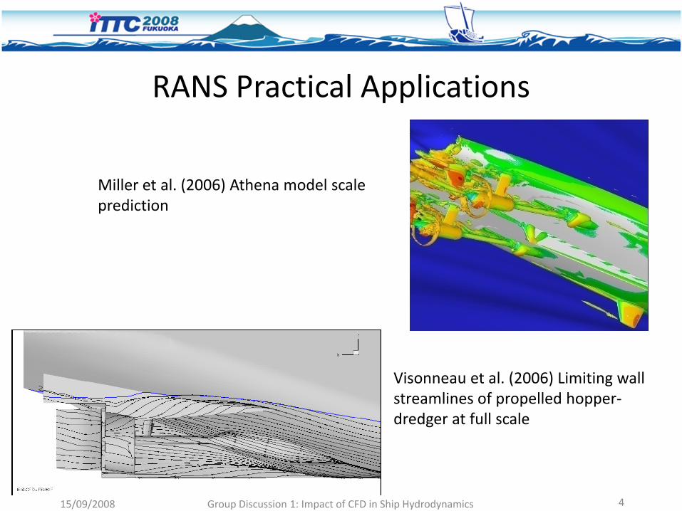
RANS Practical Applications
Miller et al. (2006) Athena model scale prediction
Visonneau et al. (2006) Limiting wall streamlines of propelled hopper‐dredger at full scale
15/09/2008 Group Discussion 1: Impact of CFD in Ship Hydrodynamics 4
15/09/2008 Group Discussion 1: Impact of CFD in Ship Hydrodynamics 5
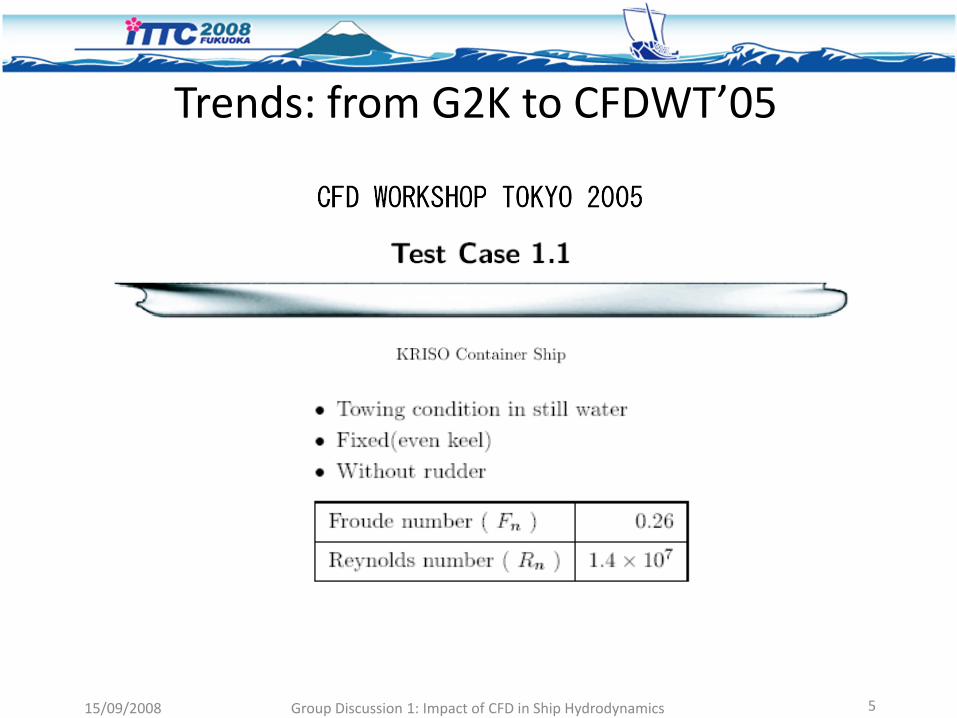
Trends: from G2K to CFDWT’05
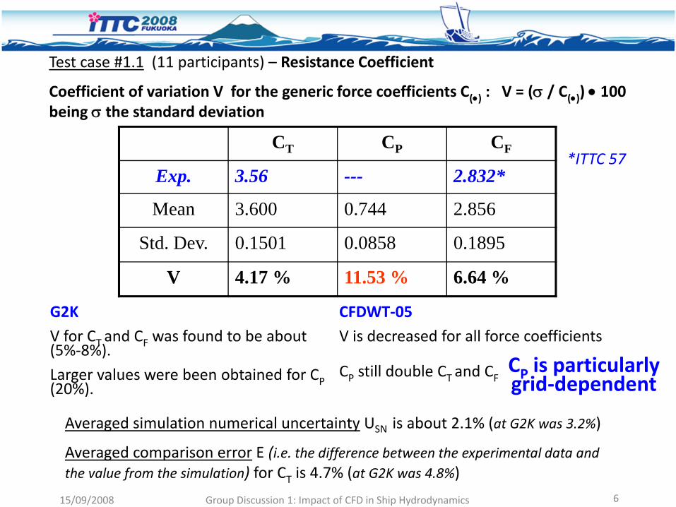
Test case #1.1 (11 participants) – Resistance Coefficient
Coefficient of variation V for the generic force coefficients C(•) : V = (σ / C(•)) • 100 being σ the standard deviation
CT CP CF
Exp. 3.56 --- 2.832*
Mean 3.600 0.744 2.856
Std. Dev. 0.1501 0.0858 0.1895
V 4.17 % 11.53 % 6.64 %
*ITTC 57
G2K
V for CT and CF was found to be about (5%‐8%).
Larger values were been obtained for CP (20%).
CFDWT‐05
V is decreased for all force coefficients
CP still double CT and CF CP is particularly grid‐dependent
Averaged simulation numerical uncertainty USN is about 2.1% (at G2K was 3.2%)
Averaged comparison error E (i.e. the difference between the experimental data and the value from the simulation) for CT is 4.7% (at G2K was 4.8%)
15/09/2008 Group Discussion 1: Impact of CFD in Ship Hydrodynamics 6
Progress in Viscous Methods• Variety of grids and gridding techniques
– Structured grids most heavily used• Good for bare hulls and some complicated geometries
• Oversets being used more often for complicated geometries
– Unstructured grids• Hexahedral, tetrahedral, and polyhedral
• Tetrahedral and polyhedral need prism layers for boundary layer accuracy
– Cartesian with immersed boundary methods• Gridding is trivial [ O(Panel codes) ]
• Boundary layer prediction still problematic
15/09/2008 Group Discussion 1: Impact of CFD in Ship Hydrodynamics 7

GriddingVisonneau et al. (2006) Stern region of hopper‐dredger
Maki et al. (2007) Trimaran polyhedral grid
Noack (2007) Overset grids for combatant
15/09/2008 Group Discussion 1: Impact of CFD in Ship Hydrodynamics 8
Progress in Viscous Methods
• Free surface treatment– Capturing methods have become routine (Volume of Fluid and Level Set) and used by the majority of groups
– Can numerically handle very complex free surface
• Turbulence modeling– Largely one‐ and two‐equations models in practice
– Reynolds stress models by some groups for flow details
– Large Eddy Simulations (LES) and Detached Eddy Simulation (DES) seeing more use, but still limited
15/09/2008 Group Discussion 1: Impact of CFD in Ship Hydrodynamics 9
New Applications• Propulsor/Hull Interaction
– Actuator disk models– Lifting surface/panel methods– Full rotating propeller
• Drag Reduction– Microbubble and polymer effects modeled– Mostly restricted to simple flows and modeling issues
• High Speed Vessels– High Froude number– Catamarans, trimarans, slender monohulls
15/09/2008 Group Discussion 1: Impact of CFD in Ship Hydrodynamics 10
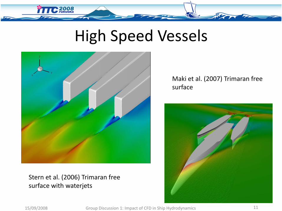
High Speed Vessels
Maki et al. (2007) Trimaran free surface
Stern et al. (2006) Trimaran free surface with waterjets
15/09/2008 Group Discussion 1: Impact of CFD in Ship Hydrodynamics 11
15/09/2008The Resistance Committee 12
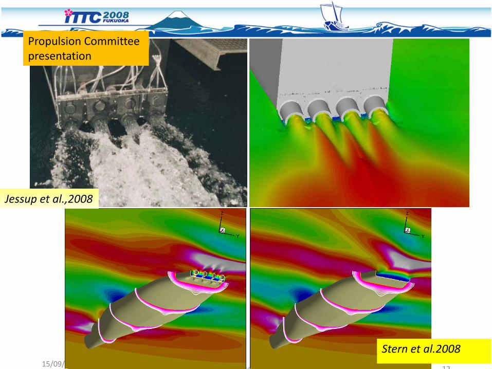
Stern et al.2008
Jessup et al.,2008
Propulsion Committee presentation
15/09/2008 Group Discussion 1: Impact of CFD in Ship Hydrodynamics 13
2005 ONR Ship Wave Breaking Workshop & Review
Wilson W. et al, 26th SNH, Rome 2006.
Focused effort to assess CFD capability as applied to ship generated waves and wave breaking.
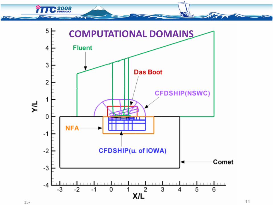
CFD solutions were generated for two full scale speeds (10.5 and 18 kn) and made by four separate groups, utilizing five CFD codes:
Das Boot / NFA / CFDSHIP‐IOWA / Comet / FluentPhysics: Potential flow, NS “no‐viscous‐flux” solver, RANSE solversFree Surface: Interface Tracking, Level Set, VoFTurbulence closure: Blended k‐ω, Blended k‐ε/k‐ω, Realizable k‐ε, k‐ω SST
Seven separate solution sets were submitted for each of the test conditions
Although focus was on free surface, total resistance was also predicted by each code for two different ship speeds and compared with model test data.
All of the CFD predictions were performed in a “blind” manner, with the results provided prior to the experimental measurements being released
15/09/2008 Group Discussion 1: Impact of CFD in Ship Hydrodynamics 14
COMPUTATIONAL DOMAINS

15/09/2008 Group Discussion 1: Impact of CFD in Ship Hydrodynamics 15
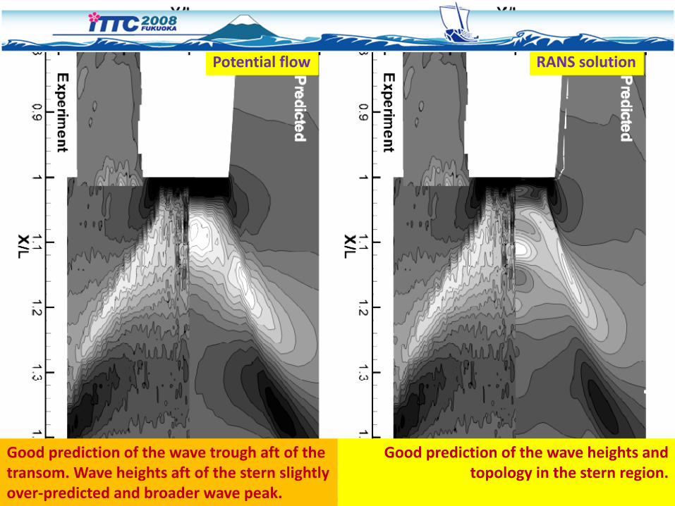
Potential flow RANS solution
Good prediction of the Kelvin wake Good prediction of the Kelvin wake
15/09/2008 Group Discussion 1: Impact of CFD in Ship Hydrodynamics 16
Potential flow RANS solution
Good prediction of the wave trough aft of the transom. Wave heights aft of the stern slightly over‐predicted and broader wave peak.
Good prediction of the wave heights and topology in the stern region.
15/09/2008 Group Discussion 1: Impact of CFD in Ship Hydrodynamics 17
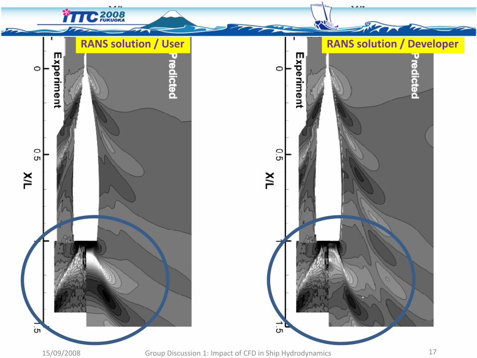
RANS solution / DeveloperRANS solution / User
15/09/2008 Group Discussion 1: Impact of CFD in Ship Hydrodynamics 18
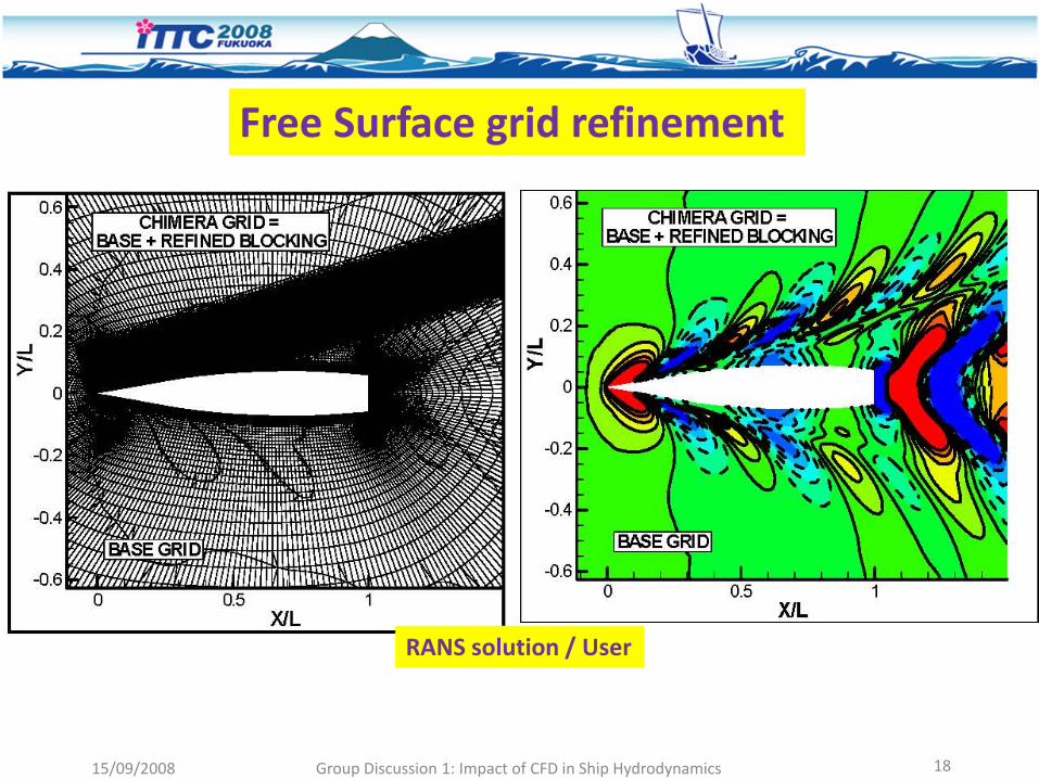
Free Surface grid refinement
RANS solution / User
15/09/2008 Group Discussion 1: Impact of CFD in Ship Hydrodynamics 19
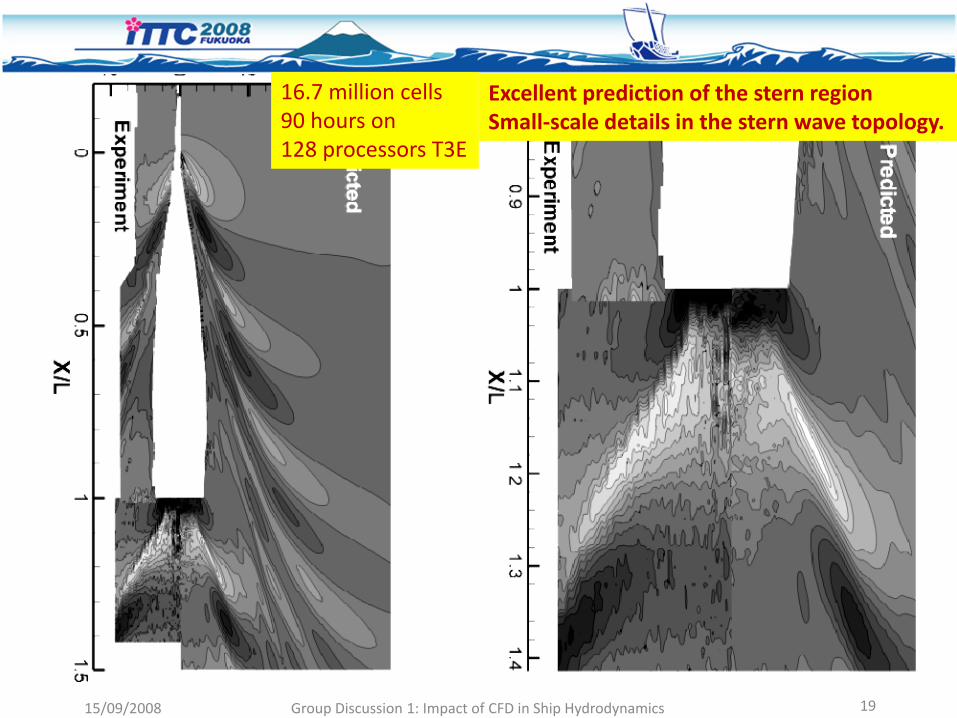
Excellent prediction of the stern region Small‐scale details in the stern wave topology.
16.7 million cells90 hours on 128 processors T3E
15/09/2008 Group Discussion 1: Impact of CFD in Ship Hydrodynamics 20
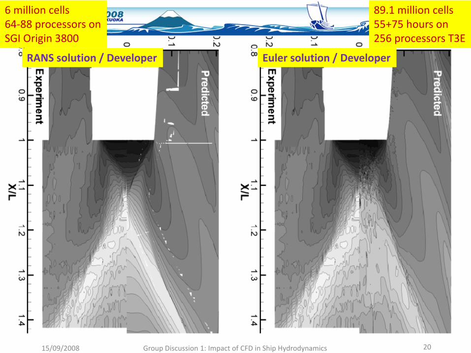
RANS solution / Developer Euler solution / Developer
89.1 million cells55+75 hours on 256 processors T3E
6 million cells64‐88 processors onSGI Origin 3800
15/09/2008 Group Discussion 1: Impact of CFD in Ship Hydrodynamics 21
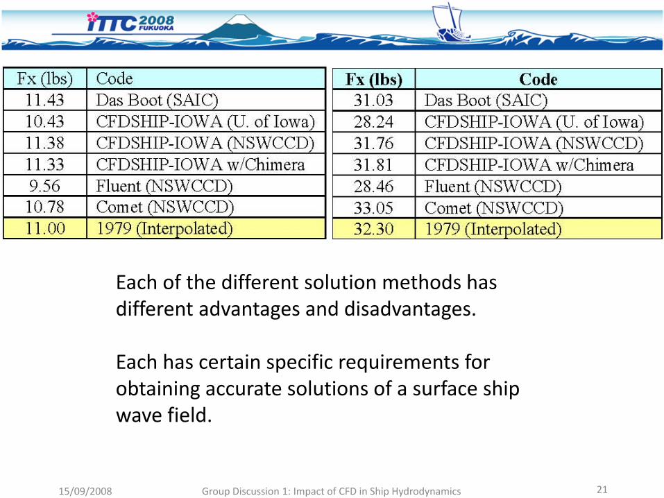
Each of the different solution methods has different advantages and disadvantages.
Each has certain specific requirements for obtaining accurate solutions of a surface ship wave field.

– Many good codes with many groups able to use the codes
– RANS having a larger role for viscous flow study
– Realistic geometries at model and full scale
– Expected to have larger role in the future with increasing experience and computer power
– Inroads to the design process (e.g. CFD on trial solutions) and to Simulation Based Design (SBD)being made
15/09/2008 Group Discussion 1: Impact of CFD in Ship Hydrodynamics 22
Optimizer
Geometry and Grid Manipulation
CFDSBD scheme

Minimize
(i) Drag/Lift and (ii) cavitation volume for two angles of attack
Original
Optimized #1
Optimized #2
3° 6°
Global Optimization of an Anti Torpedo-Torpedo tail rudder
Current status in CFD ‐ Propulsion
• Propulsion by CFD: challenges
• Propulsor flow: cavitation
• Cavitation: radiated pressures modelling
• From O.W. to propeller in behind conditions (hybrid RANS/BEM, local & global flow analysis)
• Validation data
• Analysis and design of propulsors
15/09/2008 Group Discussion 1: Impact of CFD in Ship Hydrodynamics 24
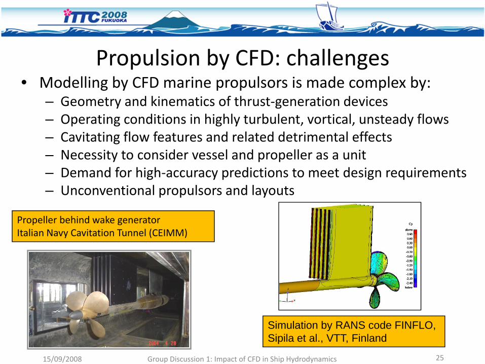
Propulsion by CFD: challenges• Modelling by CFD marine propulsors is made complex by:
– Geometry and kinematics of thrust‐generation devices– Operating conditions in highly turbulent, vortical, unsteady flows– Cavitating flow features and related detrimental effects– Necessity to consider vessel and propeller as a unit– Demand for high‐accuracy predictions to meet design requirements – Unconventional propulsors and layouts
Propeller behind wake generatorItalian Navy Cavitation Tunnel (CEIMM)
Simulation by RANS code FINFLO, Sipila et al., VTT, Finland
15/09/2008 Group Discussion 1: Impact of CFD in Ship Hydrodynamics 25

Propulsion by CFD: a bit of history• Current targets:
– Compute propeller KT, KQ within 2‐5% accuracy– Predict cavitation inception and analyse cavitating‐flow dynamics– Describe off‐design conditions– Simulate propelled vessel operations (propulsion test, manouvers,
…)• Review of methodologies:
– From early 1990’ first applications of RANS to model non‐cavitating propellers in uniform flow
– Milestone: 22nd ITTC Workshop, 1998 – By end of 1990’ extensions to hull‐propeller flows and to cavitation
• State‐of‐the‐art:– RANS models being widely used for analysis (… and design?)– Commercial as well as in‐house developed codes (most of the latter
derived from existing hull‐viscous flow codes)– Promising results by LES models
15/09/2008 Group Discussion 1: Impact of CFD in Ship Hydrodynamics 26
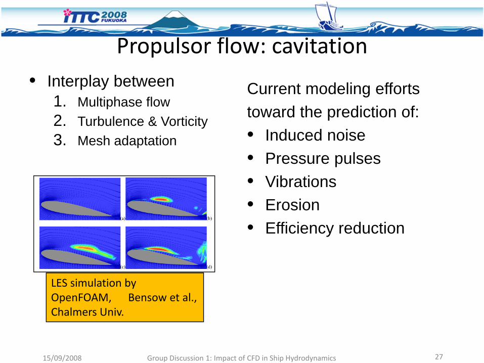
Propulsor flow: cavitation
LES simulation byOpenFOAM, Bensow et al., Chalmers Univ.
• Interplay between1. Multiphase flow 2. Turbulence & Vorticity3. Mesh adaptation
15/09/2008 Group Discussion 1: Impact of CFD in Ship Hydrodynamics 27
Current modeling effortstoward the prediction of:• Induced noise• Pressure pulses • Vibrations• Erosion• Efficiency reduction

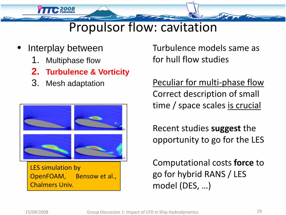
Propulsor flow: cavitation
LES simulation byOpenFOAM, Bensow et al., Chalmers Univ.
• Interplay between1. Multiphase flow 2. Turbulence & Vorticity3. Mesh adaptation
15/09/2008 Group Discussion 1: Impact of CFD in Ship Hydrodynamics 28
Barotropic models: • Arbitrary state eq. : p=f(rho)• Same continuity+momentum eqs. as non‐cavitating flow• Limit: no variable‐density induced vorticity production
Multi‐phase homogeneous mixture models:Phases: water, vapor (in some models also non‐condensable gas)Interface capturing scheme: VoFTransport equation for phases concentration (e.g., vapor volume fraction)Key issue: vapor source and destruction terms (i.e., from R‐P eq.)Pressure‐density coupling: pressure correction or artificial compressibility
Propulsor flow: cavitation
LES simulation byOpenFOAM, Bensow et al., Chalmers Univ.
• Interplay between1. Multiphase flow 2. Turbulence & Vorticity3. Mesh adaptation
15/09/2008 Group Discussion 1: Impact of CFD in Ship Hydrodynamics 29
Turbulence models same as for hull flow studies
Peculiar for multi‐phase flowCorrect description of small time / space scales is crucial
Recent studies suggest the opportunity to go for the LES
Computational costs force to go for hybrid RANS / LES model (DES, …)

Propulsor flow: cavitation
LES simulation byOpenFOAM, Bensow et al., Chalmers Univ.
• Interplay between1. Multiphase flow 2. Turbulence & Vorticity3. Mesh adaptation
15/09/2008 Group Discussion 1: Impact of CFD in Ship Hydrodynamics 30
RANS code ISIS, Visonneau et.al., CNRS
Cavitation: radiated pressures modelling• Reference problem:
– Compute pressure fluctuations induced by propeller on plate hull– Propeller excitations at multiples of blade‐passing frequency
• Viscous‐flow methods: direct computation of pressure field– Scale‐resolving is critical: LES better than RANS– Compressibility effects should be taken into account
• Hydroacoustic models:– Excitation generation and propagation problems decoupled (see
ITTC Cavitation Committee report for references)– Pressure pulses from wave‐propagation equations (compressible
flow)– Effect of solid boundaries through suitable scattering models
15/09/2008 Group Discussion 1: Impact of CFD in Ship Hydrodynamics 31
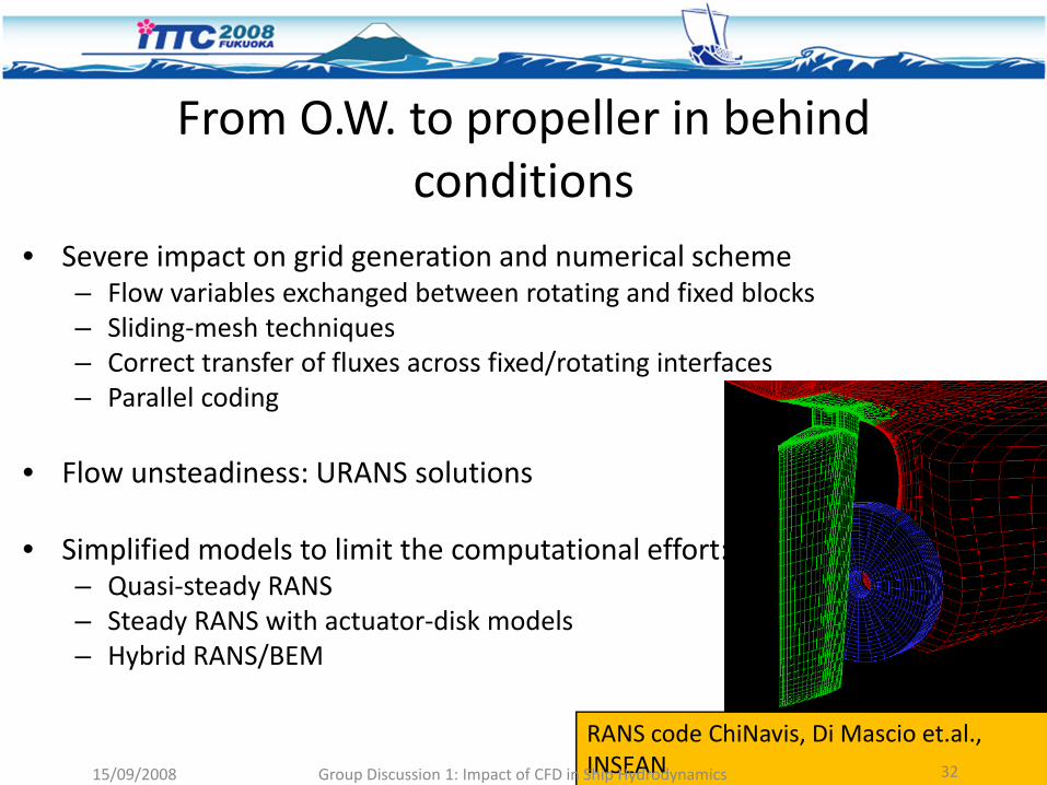
From O.W. to propeller in behindconditions
• Severe impact on grid generation and numerical scheme– Flow variables exchanged between rotating and fixed blocks– Sliding‐mesh techniques– Correct transfer of fluxes across fixed/rotating interfaces– Parallel coding
• Flow unsteadiness: URANS solutions
• Simplified models to limit the computational effort:– Quasi‐steady RANS– Steady RANS with actuator‐disk models– Hybrid RANS/BEM
RANS code ChiNavis, Di Mascio et.al., INSEAN15/09/2008 Group Discussion 1: Impact of CFD in Ship Hydrodynamics 32
Zoom in: hybrid RANS/BEM
• The concept of actuator disk revisited
• ‘Smart’ coupling of viscous and inviscid solvers: – RANS to describe viscous flow around hull w/o propeller – Inviscid flow BEM to describe propeller flow
• RANS‐BEM coupling via generalized body‐force approach– Propeller action recast as source terms in the RHS of N‐S
equations– Intensity of source terms from propeller loading by BEM
• Hull‐propeller‐rudder interactions by steady‐RANS
15/09/2008 Group Discussion 1: Impact of CFD in Ship Hydrodynamics 3315/09/2008 Group Discussion 1: Impact of CFD in Ship Hydrodynamics 33
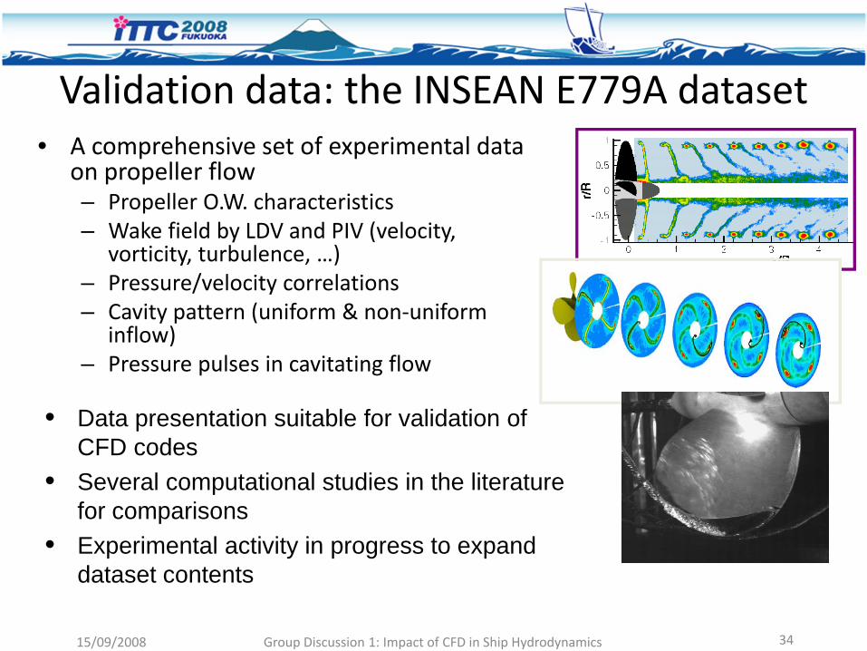
Validation data: the INSEAN E779A dataset• A comprehensive set of experimental data
on propeller flow – Propeller O.W. characteristics– Wake field by LDV and PIV (velocity,
vorticity, turbulence, …)– Pressure/velocity correlations– Cavity pattern (uniform & non‐uniform
inflow)– Pressure pulses in cavitating flow
• Data presentation suitable for validation of CFD codes
• Several computational studies in the literature for comparisons
• Experimental activity in progress to expand dataset contents
15/09/2008 Group Discussion 1: Impact of CFD in Ship Hydrodynamics 34
Analysis and design of propulsors• Impressive enhancements have been achieved in analyzing
propulsors flow by CFD• In contrast, the impact of CFD on design is still limited• Standard approach still rely on designer’s expertise and on
inviscid‐flow models: lifting‐line , vortex lattice methods• CFD limited to late‐stage verifications (similar to model
tests)• True CFD‐based design still missing• Existing applications demonstrate that modern
optimization techniques (multi‐objective, multi‐disciplinary, variable‐fidelity models) can provide a sensible improvement of design techniques
15/09/2008 Group Discussion 1: Impact of CFD in Ship Hydrodynamics 35
l lConclusions ‐ propulsion
• RANS d l id l d f i l t d ll fl t di• RANS models widely used for isolated propeller flow studies– Open water characteristics reasonably accurate
• LES models being promising– Attempts to limit LES computational effort: hybrid LES/RANS
• Hull‐propeller flow by fully RANS still very demanding– Hybrid RANS/Inviscid models appealing for hull‐propeller studiesHybrid RANS/Inviscid models appealing for hull propeller studies
• Cavitation modelling under development– Reliable predictions of blade sheet cavitation
Current efforts to improve prediction of pressure pulses erosion risk– Current efforts to improve prediction of pressure pulses, erosion risk• Examples of validity of CFD for extrapolation to full scale • Impact of CFD into design to be increased
15/09/2008 Group Discussion 1: Impact of CFD in Ship Hydrodynamics 18