Embed Size (px)
Citation preview
0
Current Status of Fukushima Dai-ichi NPP and Future Plan
November 7, 2013
Kazuhiko YAMASHITAKazuhiko YAMASHITATokyo Electric Power Company
The Fourth International Symposium on Innovative Nuclear Energy System(INES-4),6-8 November 2013, Tokyo, Japan
1
Contents Contents
1. Overview of Earthquake and Tsunami
2. Outline of Accident and Lessons Learned
3. Current Status of Fukushima Dai-ichi NPP (1F)
4. Mid/Long -Term Roadmap for Decommissioning
5. Long-Term Process In Preparation for Fuel Debris Removal
6. Remaining Challenges for Fuel Debris Retrieval
2
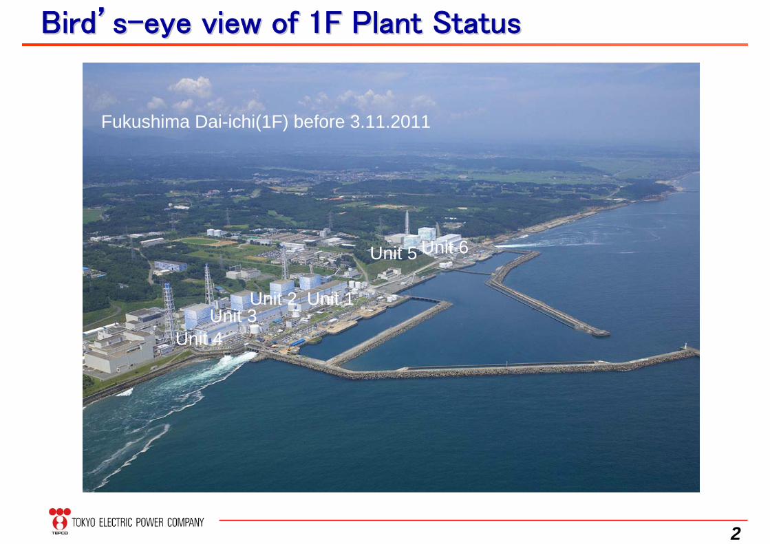
BirdBird’’ss--eye view of 1F Plant Statuseye view of 1F Plant Status
Unit 6Unit 5
Unit 1Unit 2Unit 3
Unit 4
Fukushima Dai-ichi(1F) before 3.11.2011
3
1. Overview of Earthquake and Tsunami
4
震源
原子力発電所
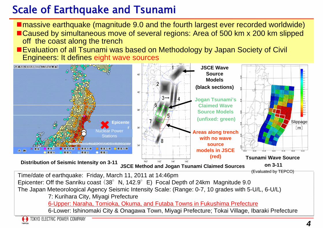
Time/date of earthquake: Friday, March 11, 2011 at 14:46pmEpicenter: Off the Sanriku coast (38°N, 142.9°E) Focal Depth of 24km Magnitude 9.0The Japan Meteorological Agency Seismic Intensity Scale: (Range: 0-7, 10 grades with 5-U/L, 6-U/L)
7: Kurihara City, Miyagi Prefecture6-Upper: Naraha, Tomioka, Okuma, and Futaba Towns in Fukushima Prefecture6-Lower: Ishinomaki City & Onagawa Town, Miyagi Prefecture; Tokai Village, Ibaraki Prefecture
Scale of Earthquake and TsunamiScale of Earthquake and Tsunami
Distribution of Seismic Intensity on 3-11
massive earthquake (magnitude 9.0 and the fourth largest ever recorded worldwide)Caused by simultaneous move of several regions: Area of 500 km x 200 km slipped
off the coast along the trenchEvaluation of all Tsunami was based on Methodology by Japan Society of Civil
Engineers: It defines eight wave sources
Slippage[m]
Tsunami Wave Sourceon 3-11
(Evaluated by TEPCO)JSCE Method and Jogan Tsunami Claimed Sources
JSCE Wave SourceModels
(black sections)
Jogan Tsunami’sClaimed Wave Source Models(unfixed: green)
Areas along trenchwith no wave
sourcemodels in JSCE
(red)
Epicenter
Nuclear Power Stations
5
6 号機 5 号機 1 号機 2 号機 3 号機 4 号機
放射性廃棄物
集中処理建屋
福島第一
福島第一は施設全域が浸水
(C)GeoEye
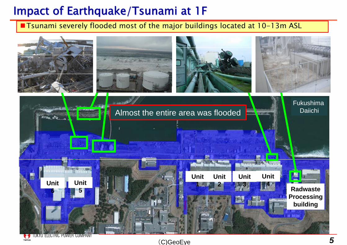
Impact of Earthquake/Tsunami at 1FImpact of Earthquake/Tsunami at 1F
Almost the entire area was flooded
Unit 1
Unit 2
Unit 3
Unit 4Unit
6Unit
5 RadwasteProcessing
building
Tsunami severely flooded most of the major buildings located at 10-13m ASL
Fukushima Daiichi
6
2. Outline of Accident and Lessons Learned
7
Image of Tsunami DamageImage of Tsunami Damage
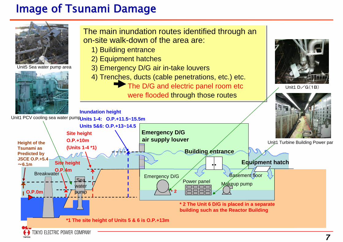
The main inundation routes identified through an on-site walk-down of the area are:
1) Building entrance2) Equipment hatches 3) Emergency D/G air in-take louvers4) Trenches, ducts (cable penetrations, etc.) etc.
The D/G and electric panel room etcwere flooded through those routes
The main inundation routes identified through an on-site walk-down of the area are:
1) Building entrance2) Equipment hatches 3) Emergency D/G air in-take louvers4) Trenches, ducts (cable penetrations, etc.) etc.
The D/G and electric panel room etcwere flooded through those routes
吸気ルーバーからの進入
Breakwater Sea
water pump
Emergency D/Gair supply louver
Site heightO.P.4m
*1 The site height of Units 5 & 6 is O.P.+13m
O.P.0m
Inundation heightUnits 1-4: O.P.+11.5~15.5mUnits 5&6: O.P.+13~14.5
* 2 The Unit 6 D/G is placed in a separate building such as the Reactor Building
Building entrance
Equipment hatch ・・
D/G
Emergency D/GPower panel
* 2
Basement floor
Height of the Tsunami as Predicted by JSCE O.P.+5.4~6.1m
Makeup pump
Site heightO.P.+10m (Units 1-4 *1)
Unit1 PCV cooling sea water pump
Unit5 Sea water pump area
Unit1 D/G(1B)
Unit1 Turbine Building Power pan
8
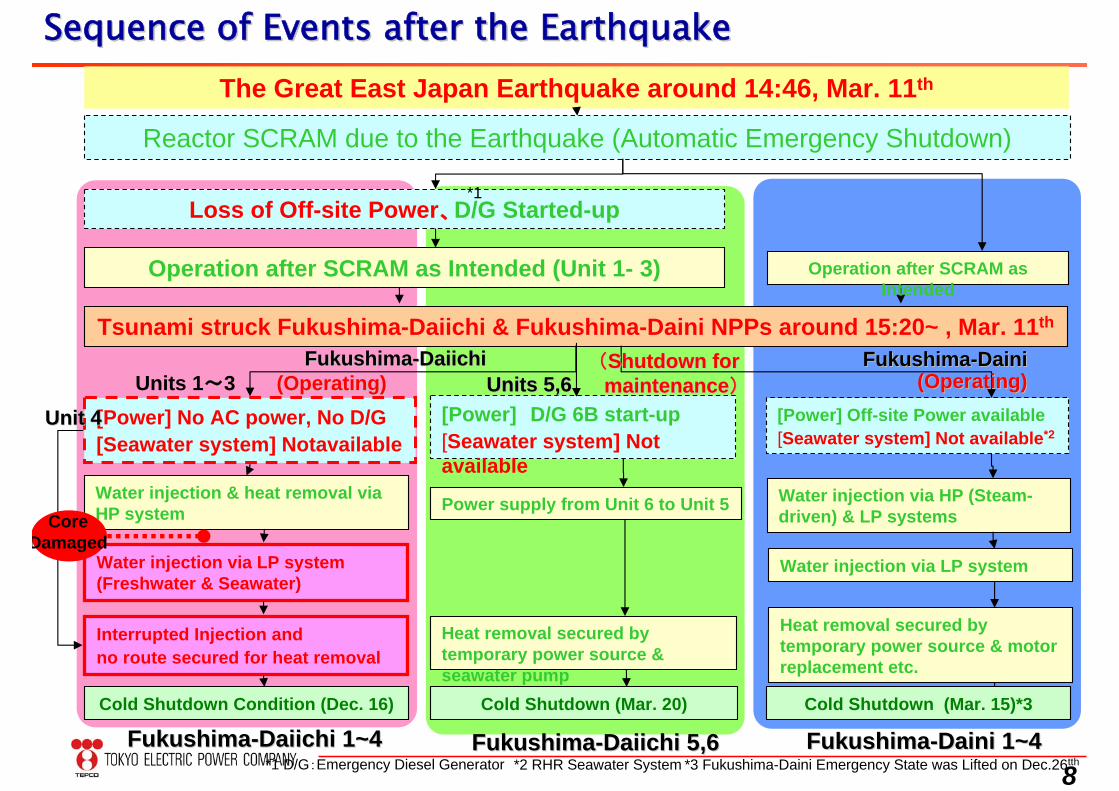
Sequence of Events after the EarthquakeSequence of Events after the EarthquakeThe Great East Japan Earthquake around 14:46, Mar. 11th
Tsunami struck Fukushima-Daiichi & Fukushima-Daini NPPs around 15:20~ , Mar. 11th
[Power] D/G 6B start-up[Seawater system] Not available
[Power] Off-site Power available[Seawater system] Not available*2
[Power] No AC power, No D/G[Seawater system] Notavailable
Reactor SCRAM due to the Earthquake (Automatic Emergency Shutdown)
Loss of Off-site Power、D/G Started-up
Operation after SCRAM as Intended (Unit 1- 3)
Units 1~3 (Operating)(Operating) Units Units 5,65,6FukushimaFukushima--DaiichiDaiichi FukushimaFukushima--DainiDaini
(Operating)(Operating)
Water injection & heat removal via HP system
Water injection via LP system (Freshwater & Seawater)
Power supply from Unit 6 to Unit 5
Interrupted Injection andno route secured for heat removal
Heat removal secured by temporary power source & seawater pump
Water injection via HP (Steam-driven) & LP systems
Water injection via LP system
Heat removal secured by temporary power source & motor replacement etc.
Unit Unit 44
FukushimaFukushima--Daiichi 1~4Daiichi 1~4 FukushimaFukushima--DaiDaiichichi 5,6i 5,6 FukushimaFukushima--Daini 1~4Daini 1~4
*1
Cold Shutdown Condition (Dec. 16)
*2 RHR Seawater System*1 D/G:Emergency Diesel Generator *3 Fukushima-Daini Emergency State was Lifted on Dec.26tth
Cold Shutdown (Mar. 20) Cold Shutdown (Mar. 15)*3
Operation after SCRAM as Intended
((Shutdown for Shutdown for maintenancemaintenance))
CoreDamaged
9
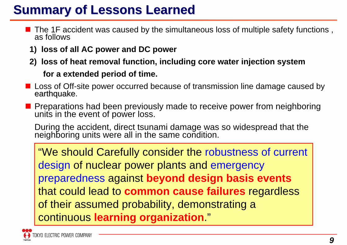
The 1F accident was caused by the simultaneous loss of multiple safety functions , as follows
1) loss of all AC power and DC power 2) loss of heat removal function, including core water injection system
for a extended period of time. Loss of Off-site power occurred because of transmission line damage caused by
earthquakeearthquake. Preparations had been previously made to receive power from neighboring
units in the event of power loss. During the accident, direct tsunami damage was so widespread that the neighboring units were all in the same condition.
Summary of Lessons LearnedSummary of Lessons Learned
“We should Carefully consider the robustness of current design of nuclear power plants and emergency preparedness against beyond design basis eventsthat could lead to common cause failures regardless of their assumed probability, demonstrating a continuous learning organization.”
10
3. Current Status of Fukushima Dai-ichi NPP(1F)
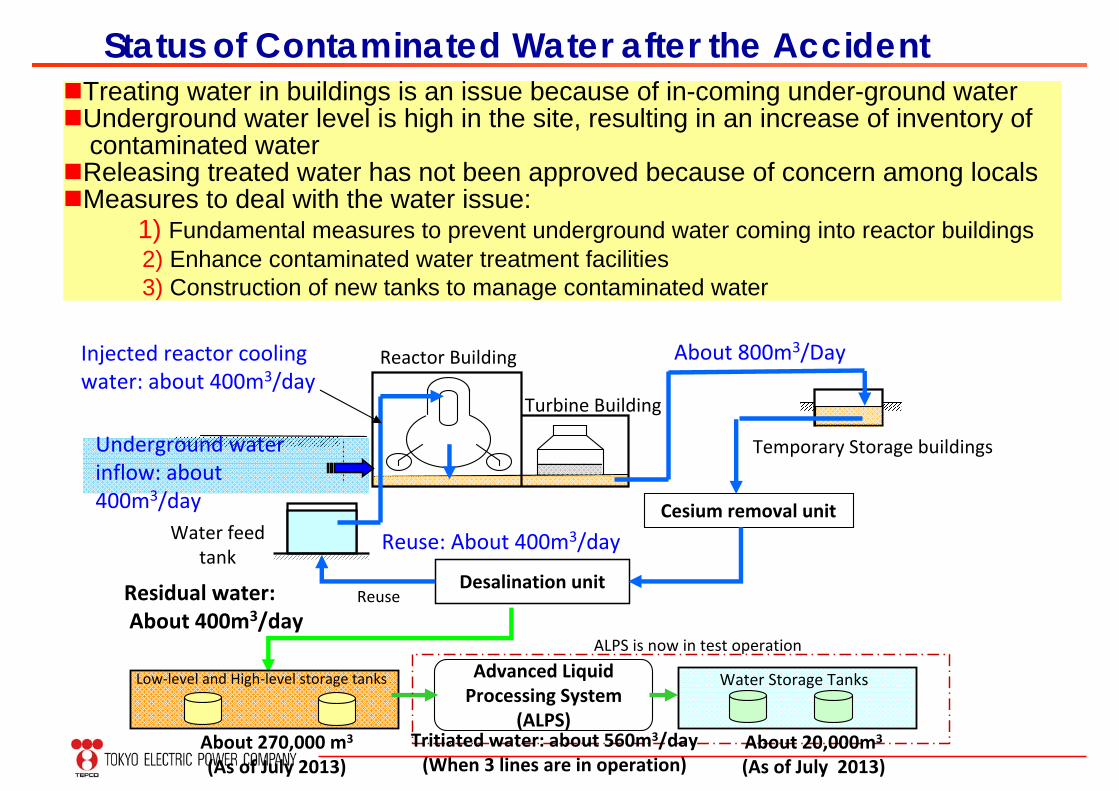
Status of Contaminated Water after the Accident
Reactor Building
Turbine Building
Temporary Storage buildings
Water feed tank
Desalination unit
Cesium removal unit
Low‐level and High‐level storage tanks Advanced Liquid Processing System
(ALPS)
Water Storage Tanks
Underground water inflow: about 400m3/day
Injected reactor cooling water: about 400m3/day
ReuseResidual water:About 400m3/day
ALPS is now in test operation
About 800m3/Day
Reuse: About 400m3/day
About 270,000 m3
(As of July 2013)Tritiated water: about 560m3/day(When 3 lines are in operation)
About 20,000m3
(As of July 2013)
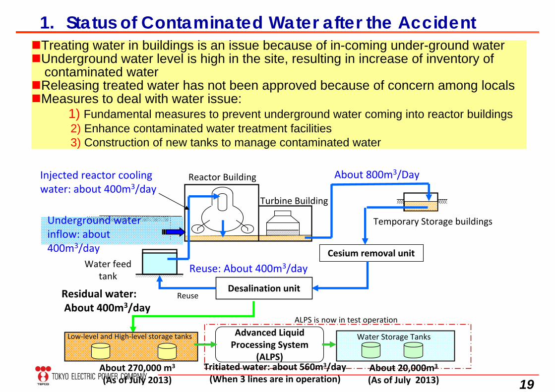
Treating water in buildings is an issue because of in-coming under-ground waterUnderground water level is high in the site, resulting in an increase of inventory of
contaminated waterReleasing treated water has not been approved because of concern among localsMeasures to deal with the water issue:
1) Fundamental measures to prevent underground water coming into reactor buildings2) Enhance contaminated water treatment facilities 3) Construction of new tanks to manage contaminated water
12
0
10
20
30
40
50
60
70
80
90
100
7/26 8/5 8/15 8/25 9/4 9/14 9/24 10/4 10/14 10/24 11/3
℃
0
10
20
30
40
50
60
70
80
90
100
7/26 8/5 8/15 8/25 9/4 9/14 9/24 10/4 10/14 10/24 11/3
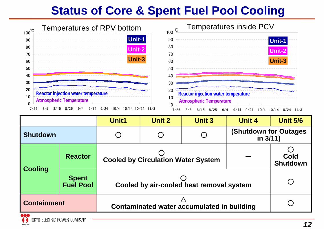
℃Temperatures of RPV bottom Temperatures inside PCV
Spent Fuel Pool
Reactor
○〇
Cooled by air-cooled heat removal system
○△
Contaminated water accumulated in buildingContainment
○Cold
Shutdown-
○Cooled by Circulation Water System
Cooling
(Shutdown for Outages in 3/11)○○○Shutdown
Unit 5/6Unit 4Unit 3Unit 2Unit1
Unit-1Unit-2Unit-3
Reactor injection water temperature
Unit-1Unit-2Unit-3
Reactor injection water temperature
Status of Core & Spent Fuel Pool Cooling
Atmospheric Temperature Atmospheric Temperature
13
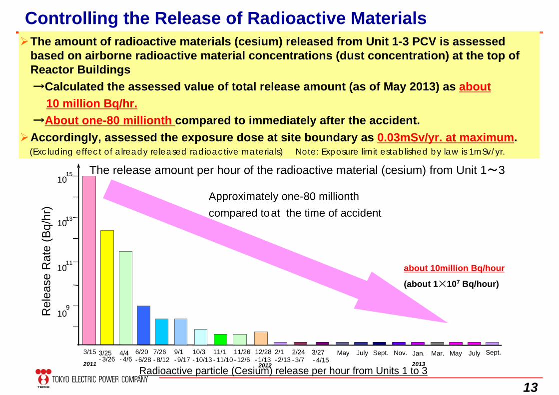
The amount of radioactive materials (cesium) released from Unit 1-3 PCV is assessed based on airborne radioactive material concentrations (dust concentration) at the top of Reactor Buildings→Calculated the assessed value of total release amount (as of May 2013) as about
10 million Bq/hr.→About one-80 millionth compared to immediately after the accident.
Accordingly, assessed the exposure dose at site boundary as 0.03mSv/yr. at maximum.(Excluding effect of already released radioactive materials) Note: Exposure limit established by law is 1mSv/yr.
Controlling the Release of Radioactive Materials
Approximately one-80 millionthcompared to at the time of accident
The release amount per hour of the radioactive material (cesium) from Unit 1~3
Rel
ease
Rat
e (B
q/hr
)
Radioactive particle (Cesium) release per hour from Units 1 to 3
1015
1013
1011
109
3/15 3/25- 3/26
6/20-6/28
4/4- 4/6
7/26- 8/12
9/1- 9/17
10/3-10/13
11/1- 11/10
11/26- 12/6
12/28-1/13
2/1-2/13
2/24-3/7
3/27- 4/15
May July
about 10million Bq/hour
(about 1×10⁷ Bq/hour)
Sept. Nov. Jan. Mar. May July2011 2012 2013
Sept.
14
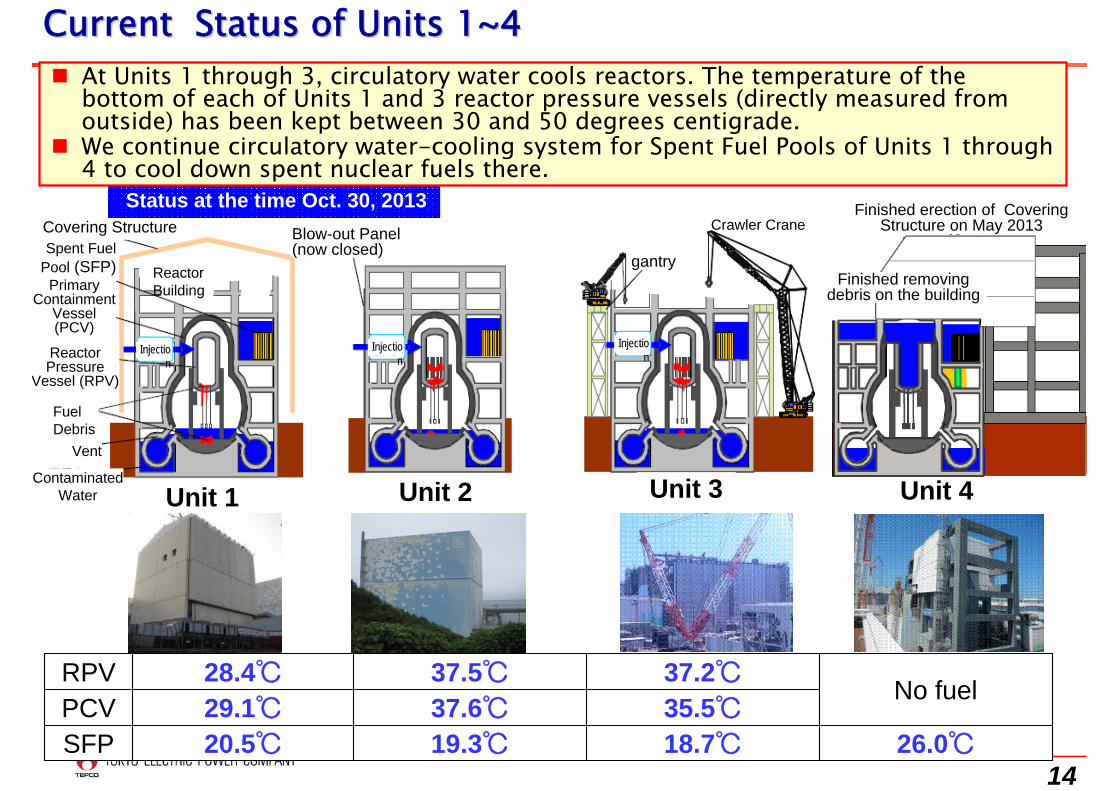
Current Status of Units 1~4Current Status of Units 1~4
35.5℃37.6℃29.1℃PCVNo fuel
37.2℃37.5℃28.4℃RPV
26.0℃18.7℃SFP 19.3℃20.5℃
Status at the time Oct. 30, 2013
At Units 1 through 3, circulatory water cools reactors. The temperature of the bottom of each of Units 1 and 3 reactor pressure vessels (directly measured from outside) has been kept between 30 and 50 degrees centigrade.
We continue circulatory water-cooling system for Spent Fuel Pools of Units 1 through 4 to cool down spent nuclear fuels there.
Unit 1 Unit 4Unit 3Unit 2
Spent Fuel Pool (SFP)
Reactor Pressure
Vessel (RPV)
Contaminated Water
Primary Containment
Vessel (PCV)
Covering Structure
Reactor Building
Blow-out Panel(now closed)
Crawler Crane
Vent
Injection
Injection
Injection
gantry
Finished erection of Covering Structure on May 2013
Finished removing debris on the building
Fuel Debris
15
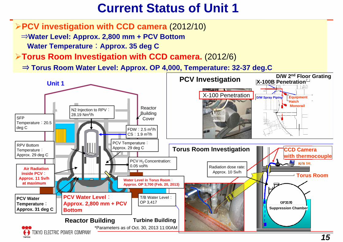
Current Status of Unit 1PCV investigation with CCD camera (2012/10)
⇒Water Level: Approx. 2,800 mm + PCV BottomWater Temperature:Approx. 35 deg C
Torus Room Investigation with CCD camera. (2012/6)⇒ Torus Room Water Level: Approx. OP 4,000, Temperature: 32-37 deg.C
X-100Bペネ
PCV Investigation
Torus Room Investigation
Radiation dose rate:Approx. 10 Sv/h
X-100 Penetration
X-100B PenetrationD/W 2nd Floor Grating
D/W Spray Piping Equipment HatchMonorail
Torus Room
CCD Camerawith thermocouple
Suppression Chamber
Reactor Building Cover
*Parameters as of Oct. 30, 2013 11:00AM
Unit 1
FDW:2.5 m3/h CS:1.9 m3/h
PCV H2 Concentration:0.05 vol%
SFP Temperature:20.5deg C
N2 Injection to RPV:28.19 Nm3/h
RPV Bottom Temperature:Approx. 29 deg C
PCV Temperature:Approx. 29 deg C
Reactor Building Turbine Building
T/B Water Level:OP 3,417
PCV Water Level:Approx. 2,800 mm + PCV Bottom
PCV Water Temperature:Approx. 31 deg C
Water Level in Torus Room:Approx. OP 3,700 (Feb. 20, 2013)
Air Radiation inside PCV:
Approx. 11 Sv/h at maximum
16
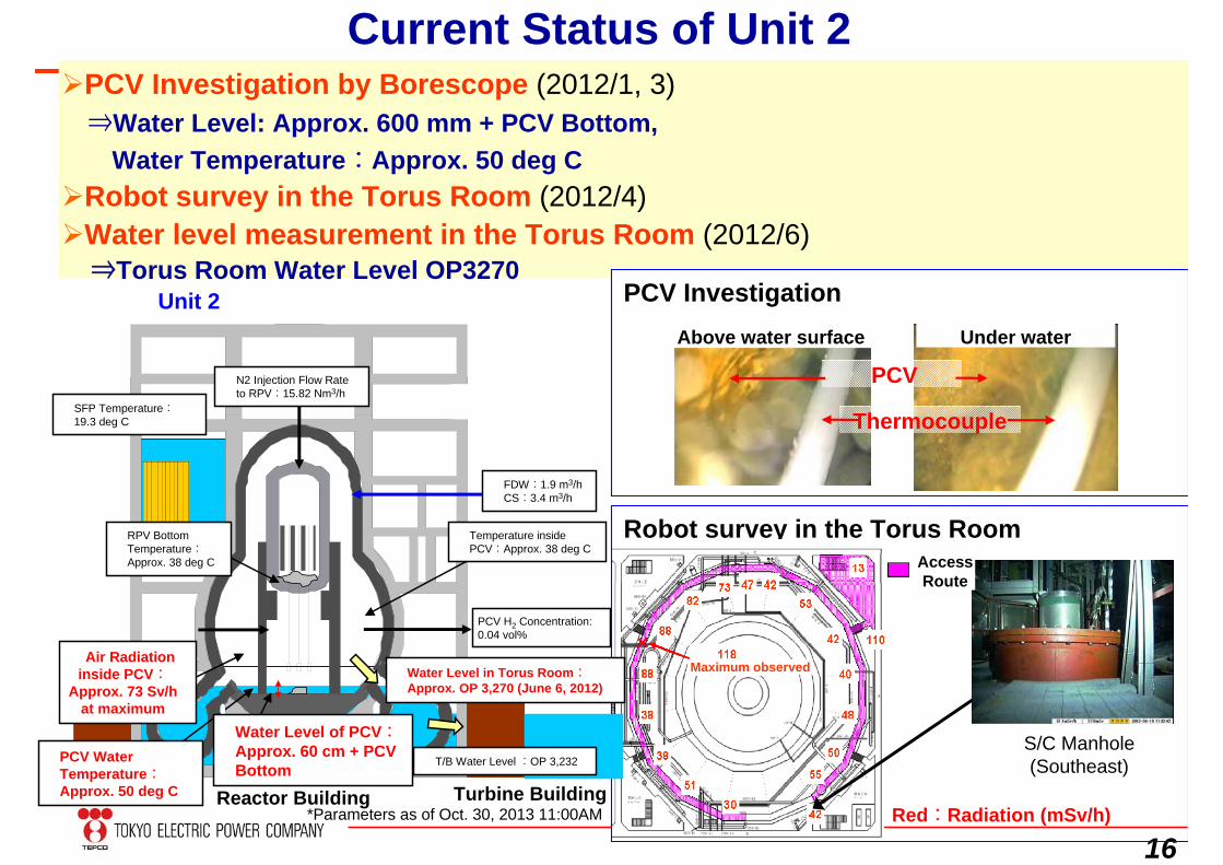
PCV Investigation by Borescope (2012/1, 3)⇒Water Level: Approx. 600 mm + PCV Bottom,
Water Temperature:Approx. 50 deg CRobot survey in the Torus Room (2012/4)Water level measurement in the Torus Room (2012/6)
⇒Torus Room Water Level OP3270PCV Investigation
Under waterAbove water surface
Thermocouple
PCV
Robot survey in the Torus Room
Red:Radiation (mSv/h)
S/C Manhole(Southeast)
Current Status of Unit 2
AccessRoute
Maximum observed
Unit 2
FDW:1.9 m3/hCS:3.4 m3/h
SFP Temperature:19.3 deg C
N2 Injection Flow Rate to RPV:15.82 Nm3/h
RPV Bottom Temperature:Approx. 38 deg C
Temperature inside PCV:Approx. 38 deg C
Reactor Building Turbine Building
T/B Water Level :OP 3,232PCV Water Temperature:Approx. 50 deg C
Water Level of PCV:Approx. 60 cm + PCV Bottom
Air Radiation inside PCV:
Approx. 73 Sv/h at maximum
Water Level in Torus Room:Approx. OP 3,270 (June 6, 2012)
PCV H2 Concentration:0.04 vol%
*Parameters as of Oct. 30, 2013 11:00AM
17
安全第一 福島第一安全第一 福島第一安全第一 福島第一安全第一 福島第一安全第一 福島第一安全第一 福島第一安全第一 福島第一安全第一 福島第一安全第一 福島第一安全第一 福島第一安全第一 福島第一
Unit 3
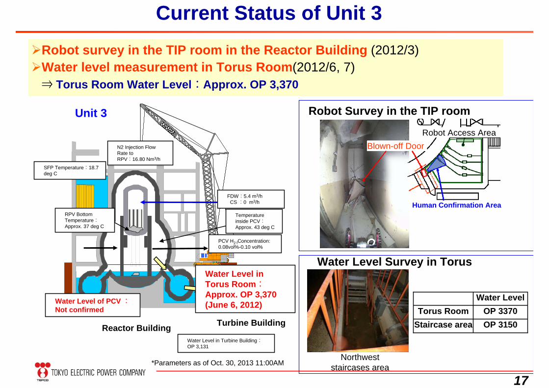
Robot survey in the TIP room in the Reactor Building (2012/3)Water level measurement in Torus Room(2012/6, 7)
⇒ Torus Room Water Level:Approx. OP 3,370
Robot Survey in the TIP room
Water Level Survey in Torus
Northwest staircases area
Current Status of Unit 3
Blown-off Door
Human Confirmation Area
Robot Access Area
OP 3370Torus RoomOP 3150
Water Level
Staircase area
FDW:5.4 m3/hCS :0 m3/h
PCV H2 fConcentration:0.08vol%-0.10 vol%
SFP Temperature:18.7 deg C
RPV Bottom Temperature:Approx. 37 deg C
Temperature inside PCV:Approx. 43 deg C
Reactor Building Turbine Building
Water Level in Turbine Building:OP 3,131
Water Level in Torus Room:Approx. OP 3,370 (June 6, 2012)Water Level of PCV :
Not confirmed
N2 Injection Flow Rate toRPV:16.80 Nm3/h
*Parameters as of Oct. 30, 2013 11:00AM
18
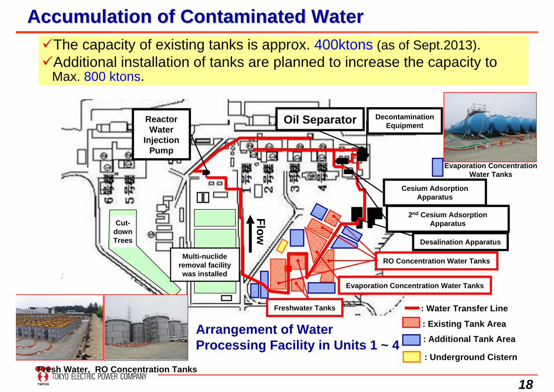
Accumulation of Contaminated WaterAccumulation of Contaminated Water
Arrangement of Water Processing Facility in Units 1 ~ 4
Oil Separator Decontamination Equipment
Cesium Adsorption Apparatus
Desalination Apparatus
Freshwater Tanks
Reactor Water
Injection Pump
RO Concentration Water Tanks
2nd Cesium Adsorption Apparatus
Evaporation Concentration Water TanksFlow
Cut-down Trees
Multi-nuclide removal facility was installed
: Existing Tank Area
: Water Transfer Line
Fresh Water, RO Concentration Tanks
Evaporation Concentration Water Tanks
: Underground Cistern
: Additional Tank Area
The capacity of existing tanks is approx. 400ktons (as of Sept.2013). Additional installation of tanks are planned to increase the capacity to
Max. 800 ktons.
19
1. Status of Contaminated Water after the Accident
Reactor Building
Turbine Building
Temporary Storage buildings
Water feed tank
Desalination unit
Cesium removal unit
Low‐level and High‐level storage tanks Advanced Liquid Processing System
(ALPS)
Water Storage Tanks
Underground water inflow: about 400m3/day
Injected reactor cooling water: about 400m3/day
ReuseResidual water:About 400m3/day
ALPS is now in test operation
About 800m3/Day
Reuse: About 400m3/day
About 270,000 m3
(As of July 2013)Tritiated water: about 560m3/day(When 3 lines are in operation)
About 20,000m3
(As of July 2013)
Treating water in buildings is an issue because of in-coming under-ground waterUnderground water level is high in the site, resulting in increase of inventory of
contaminated waterReleasing treated water has not been approved because of concern among localsMeasures to deal with water issue:
1) Fundamental measures to prevent underground water coming into reactor buildings2) Enhance contaminated water treatment facilities 3) Construction of new tanks to manage contaminated water
20
0
100000
200000
300000
400000
500000
600000
700000
800000
900000
H25.3
H25.6
H25.9
H25.1
2
H26.3
H26.6
H26.9
H26.1
2
H27.3
H27.6
H27.9
H27.1
2
H28.3
貯蔵
量(m
3)
<総貯蔵量>
<RO処理水(淡水)>
<RO濃縮水>+<濃縮廃液>(塩水)
<ALPS処理水(塩水)>
タンク総容量
リプレース予定量
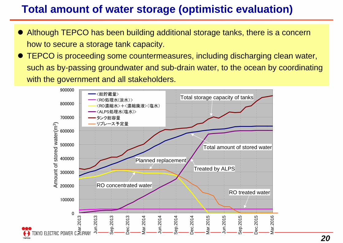
Total amount of water storage (optimistic evaluation)
Although TEPCO has been building additional storage tanks, there is a concern how to secure a storage tank capacity.
TEPCO is proceeding some countermeasures, including discharging clean water, such as by-passing groundwater and sub-drain water, to the ocean by coordinating with the government and all stakeholders.
Am
ount
of s
tore
d w
ater
(m3 )
Mar
.201
3
Jun.
2013
Sep.
2013
Dec
.201
3
Mar
.201
4
Jun.
2014
Sep.
2014
Dec
.201
4
Mar
.201
5
Jun.
2015
Sep.
2015
Dec
.201
5
Mar
.201
6
Total storage capacity of tanks
Treated by ALPS
RO treated waterRO concentrated water
Planned replacement
Total amount of stored water
21
0
100000
200000
300000
400000
500000
600000
700000
800000
900000
H25.3
H25.6
H25.9
H25.1
2
H26.3
H26.6
H26.9
H26.1
2
H27.3
H27.6
H27.9
H27.1
2
H28.3
貯蔵
量(m
3)
<総貯蔵量>
<RO処理水(淡水)>
<RO濃縮水>+<濃縮廃液>(塩水)
<ALPS処理水(塩水)>
タンク総容量
リプレース予定量
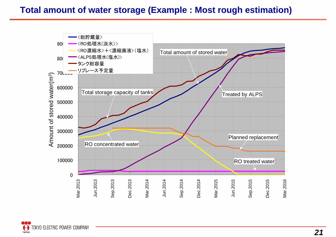
Total amount of water storage (Example : Most rough estimation)
Amou
nt o
f sto
red
wat
er(m
3 )
Mar
.201
3
Jun.
2013
Sep.
2013
Dec
.201
3
Mar
.201
4
Jun.
2014
Sep.
2014
Dec
.201
4
Mar
.201
5
Jun.
2015
Sep.
2015
Dec
.201
5
Mar
.201
6
Total storage capacity of tanks Treated by ALPS
RO treated water
RO concentrated waterPlanned replacement
Total amount of stored water
22
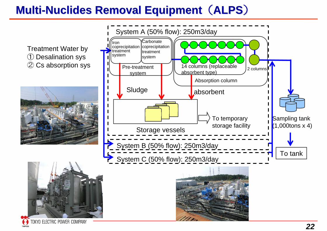
Sampling tank (1,000tons x 4)
Iron coprecipitation treatmentsystem
Carbonate coprecipitation treatment system
Storage vessels
To temporary storage facility
14 columns (replaceable absorbent type)
2 columns
System A (50% flow): 250m3/day
Sludge absorbent
Pre-treatment system
Absorption column
To tankSystem B (50% flow): 250m3/day
System C (50% flow): 250m3/day
Treatment Water by① Desalination sys② Cs absorption sys
MultiMulti--Nuclides Removal EquipmentNuclides Removal Equipment((ALPSALPS))
23
About 200m
About 500m
About 200m
About 500m
フェーシング
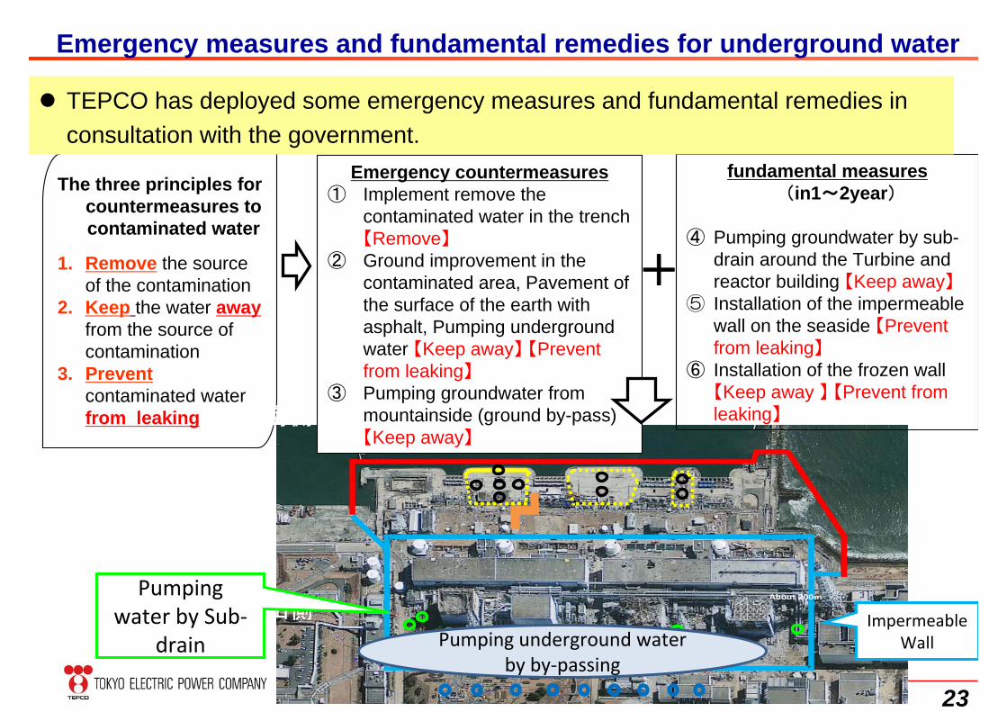
The three principles for countermeasures to contaminated water
1. Remove the source of the contamination
2. Keep the water awayfrom the source of contamination
3. Prevent contaminated water from leaking
Emergency countermeasures① Implement remove the
contaminated water in the trench 【Remove】
② Ground improvement in the contaminated area, Pavement of the surface of the earth with asphalt, Pumping underground water 【Keep away】 【Prevent from leaking】
③ Pumping groundwater from mountainside (ground by-pass) 【Keep away】
fundamental measures (in1~2year)
④ Pumping groundwater by sub-drain around the Turbine and reactor building 【Keep away】
⑤ Installation of the impermeable wall on the seaside 【Prevent from leaking】
⑥ Installation of the frozen wall【Keep away 】 【Prevent from leaking】
+
山側
海側
Emergency measures and fundamental remedies for underground water
TEPCO has deployed some emergency measures and fundamental remedies in consultation with the government.
Pumping water by Sub‐
drain Pumping underground water by by‐passing
Impermeable Wall
24
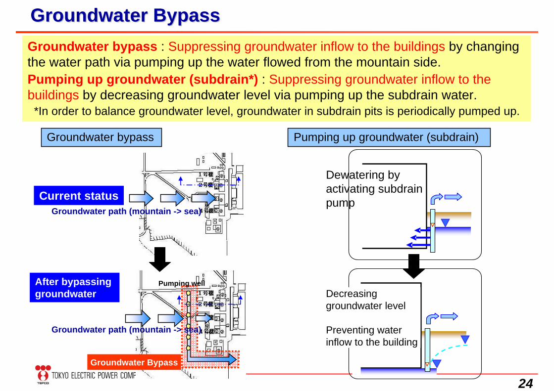
Groundwater BypassGroundwater Bypass
Pumping up groundwater (subdrain)
Groundwater bypass : Suppressing groundwater inflow to the buildings by changing the water path via pumping up the water flowed from the mountain side.Pumping up groundwater (subdrain*) : Suppressing groundwater inflow to the buildings by decreasing groundwater level via pumping up the subdrain water.
*In order to balance groundwater level, groundwater in subdrain pits is periodically pumped up.
Decreasing groundwater level
Preventing water inflow to the building
Dewatering by activating subdrain pump
Groundwater path (mountain -> sea)Current status
Pumping wellAfter bypassing groundwater
Groundwater Bypass
Groundwater bypass
Groundwater path (mountain -> sea)
25
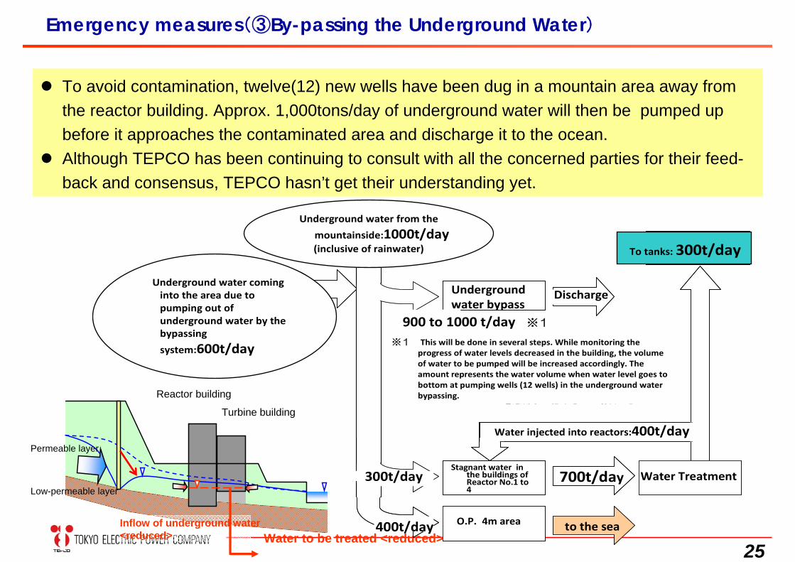
Emergency measures(③By-passing the Underground Water)
To avoid contamination, twelve(12) new wells have been dug in a mountain area away from the reactor building. Approx. 1,000tons/day of underground water will then be pumped up before it approaches the contaminated area and discharge it to the ocean.
Although TEPCO has been continuing to consult with all the concerned parties for their feed-back and consensus, TEPCO hasn’t get their understanding yet.
Inflow of underground water<reduced>
Permeable layer
Low-permeable layer
Water to be treated <reduced>
Reactor building
Turbine building
タンクへ300t/日
海抜4mエリア
700t/日
海へ
炉注量400t/日
300t/日
400t/日
水処理
地下水バイパス 放出
山側から1000t/日(降雨含む)
地下水バイパスの汲み上げ
による周辺の地下水吸いよせ600t/日 ※1 段階的に稼働する計画であり建屋内水
位低下の進捗に合わせて、水質を確認しながら揚水量を増やしていく本数値は地下水バイパスの全揚水井(12箇所)において、揚水井内の水位を底部まで低下させた場合の値
900~1,000t/日※1
1~4号機
建屋滞留水
タンクへ300t/日
海抜4mエリア
700t/日
海へ
炉注量400t/日
300t/日
400t/日
水処理
地下水バイパス 放出
山側から1000t/日(降雨含む)
地下水バイパスの汲み上げ
による周辺の地下水吸いよせ600t/日 ※1 段階的に稼働する計画であり建屋内水
位低下の進捗に合わせて、水質を確認しながら揚水量を増やしていく本数値は地下水バイパスの全揚水井(12箇所)において、揚水井内の水位を底部まで低下させた場合の値
900~1,000t/日※1
1~4号機
建屋滞留水
※1 This will be done in several steps. While monitoring the progress of water levels decreased in the building, the volume of water to be pumped will be increased accordingly. The amount represents the water volume when water level goes to bottom at pumping wells (12 wells) in the underground water bypassing.
Underground water coming into the area due to pumping out of underground water by the bypassing
system:600t/day
Underground water from the
mountainside:1000t/day (inclusive of rainwater)
900 to 1000 t/day ※1
Underground water bypass
Discharge
Water injected into reactors:400t/day
Water Treatment700t/day300t/day
400t/day O.P. 4m area
Stagnant water in the buildings of Reactor No.1 to 4
to the sea
To tanks: 300t/day
26
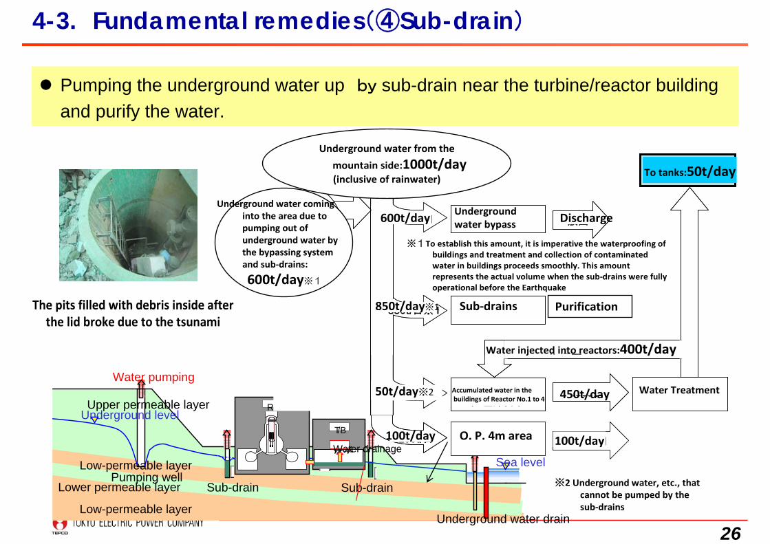
4-3. Fundamental remedies(④Sub-drain)
Pumping the underground water up by sub-drain near the turbine/reactor building and purify the water.
Low-permeable layer
Water pumping
Pumping wellLower permeable layer
Low-permeable layer
Sub-drain Sub-drain
R/B
T/B
排水Water drainage
Underground water drain
Underground level
Sea level
Upper permeable layer
タンクへ 50t/日
地下水バイパス
サブドレン
海抜4mエリア
450t/日
100t/日
炉注量400t/日
放出600t/日
50t/日※2
100t/日
水処理
850t/日※1
山側から1000t/日(降雨含む)
地下水バイパス
及びサブドレンの汲み上げによる
周辺の地下水吸いよせ600t/日
※1 建屋止水および建屋内汚染水の処理回収が計画通り進捗する必要あり本数値は震災前のサブドレン運転実績
※2 サブドレンで汲み上げきれない地下水等
1~4号機
建屋滞留水
浄化
タンクへ 50t/日
地下水バイパス
サブドレン
海抜4mエリア
450t/日
100t/日
炉注量400t/日
放出600t/日
50t/日※2
100t/日
水処理
850t/日※1
山側から1000t/日(降雨含む)
地下水バイパス
及びサブドレンの汲み上げによる
周辺の地下水吸いよせ600t/日
※1 建屋止水および建屋内汚染水の処理回収が計画通り進捗する必要あり本数値は震災前のサブドレン運転実績
※2 サブドレンで汲み上げきれない地下水等
1~4号機
建屋滞留水
浄化
Underground water coming into the area due to pumping out of underground water by the bypassing system and sub‐drains:
600t/day※1
600t/day
850t/day※1
50t/day※2
100t/day
Underground water bypass
Sub‐drains
Accumulated water in thebuildings of Reactor No.1 to 4
O. P. 4m area 100t/day
450t/day
To tanks:50t/day
Discharge
Purification
※1To establish this amount, it is imperative the waterproofing of buildings and treatment and collection of contaminated water in buildings proceeds smoothly. This amount represents the actual volume when the sub‐drains were fully operational before the Earthquake
※2 Underground water, etc., that cannot be pumped by the sub‐drains
Underground water from the
mountain side:1000t/day (inclusive of rainwater)
Water injected into reactors:400t/day
Water Treatment
The pits filled with debris inside after the lid broke due to the tsunami
27
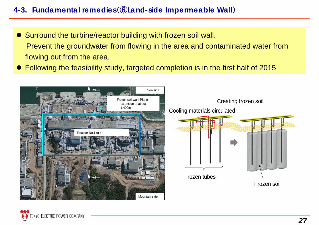
4-3. Fundamental remedies(⑥Land-side Impermeable Wall)
Surround the turbine/reactor building with frozen soil wall. Prevent the groundwater from flowing in the area and contaminated water from flowing out from the area.
Following the feasibility study, targeted completion is in the first half of 2015
凍土壁
平面延長約1400m
1~4号機
山側
海側A
A
凍土の造成
凍結管凍土
冷却材を循環
Sea side
Frozen soil wall: Plane extension of about 1,400m
Reactor No.1 to 4
Mountain side
Creating frozen soilCooling materials circulated
Frozen tubesFrozen soil
28
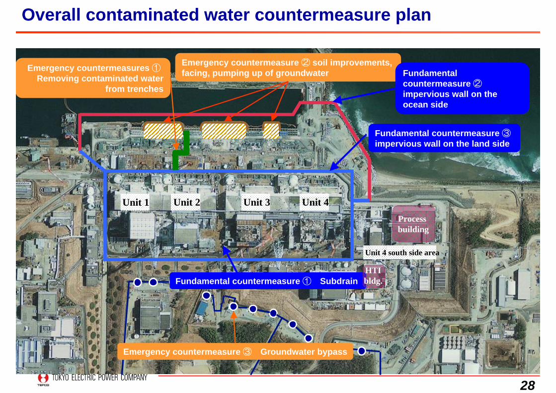
Unit 4 south side area
Unit 1 Unit 2 Unit 3 Unit 4
Emergency countermeasure ③ Groundwater bypass
Emergency countermeasure ② soil improvements, facing, pumping up of groundwater Fundamental
countermeasure ②impervious wall on the ocean side
Fundamental countermeasure ① Subdrain
Fundamental countermeasure ③impervious wall on the land side
Emergency countermeasures ①Removing contaminated water
from trenches
Process building
HTIbldg.
Overall contaminated water countermeasure plan
29
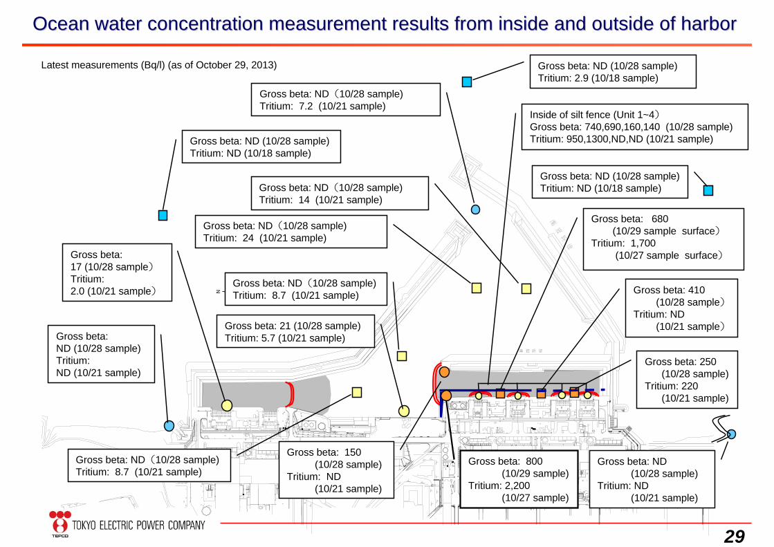
Ocean water concentration measurement results from inside and ouOcean water concentration measurement results from inside and outside of harbortside of harbor
Latest measurements (Bq/l) (as of October 29, 2013)
Gross beta: ND(10/28 sample)Tritium: 7.2 (10/21 sample)
Gross beta: ND (10/28 sample)Tritium: ND (10/21 sample)
Gross beta:17 (10/28 sample)Tritium:2.0 (10/21 sample)
Gross beta: 250(10/28 sample)
Tritium: 220(10/21 sample)
Gross beta: ND(10/28 sample)Tritium: 24 (10/21 sample)
Gross beta: ND(10/28 sample)Tritium: 8.7 (10/21 sample)
Gross beta: 21 (10/28 sample)Tritium: 5.7 (10/21 sample)
Gross beta: 410(10/28 sample)
Tritium: ND(10/21 sample)
Gross beta: 680(10/29 sample surface)
Tritium: 1,700(10/27 sample surface)
Gross beta: ND(10/28 sample)
Tritium: ND(10/21 sample)
Gross beta: 150(10/28 sample)
Tritium: ND(10/21 sample)
Gross beta: 800 (10/29 sample)
Tritium: 2,200(10/27 sample)
Inside of silt fence (Unit 1~4)Gross beta: 740,690,160,140 (10/28 sample)Tritium: 950,1300,ND,ND (10/21 sample)
Gross beta: ND(10/28 sample)Tritium: 8.7 (10/21 sample)
Gross beta: ND(10/28 sample)Tritium: 14 (10/21 sample)
Gross beta: ND (10/28 sample)Tritium: ND (10/18 sample)
Gross beta: ND (10/28 sample)Tritium: 2.9 (10/18 sample)
Gross beta: ND (10/28 sample)Tritium: ND (10/18 sample)
30
1
10
100
1000
10000
100000
1000000
10000000
3/11 6/19 9/27 1/5 4/14 7/23 10/31
2/8 5/19 8/27
I-131Cs-134Cs-137
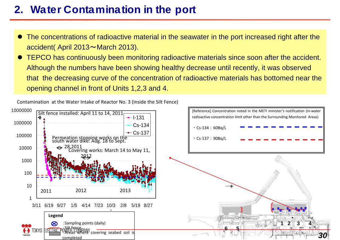
2. Water Contamination in the port
The concentrations of radioactive material in the seawater in the port increased right after the accident( April 2013~March 2013).
TEPCO has continuously been monitoring radioactive materials since soon after the accident.Although the numbers have been showing healthy decrease until recently, it was observed that the decreasing curve of the concentration of radioactive materials has bottomed near the opening channel in front of Units 1,2,3 and 4.
Silt fence installed: April 11 to 14, 2011
Permeation stopping works on the south water dike: Aug. 18 to Sept.
28,2011Covering works: March 14 to May 11,
2012
2011 2012 2013
:Sampling points (daily):Silt fence
Legend
:Areas where covering seabed soil is completed
1 2 3 456
Contamination at the Water Intake of Reactor No. 3 (inside the Silt Fence)
[Reference] Concentration noted in the METI minister’s notification (in‐water
radioactive concentration limit other than the Surrounding Monitored Areas)
・Cs‐134:60Bq/L
・Cs‐137:90Bq/L
31
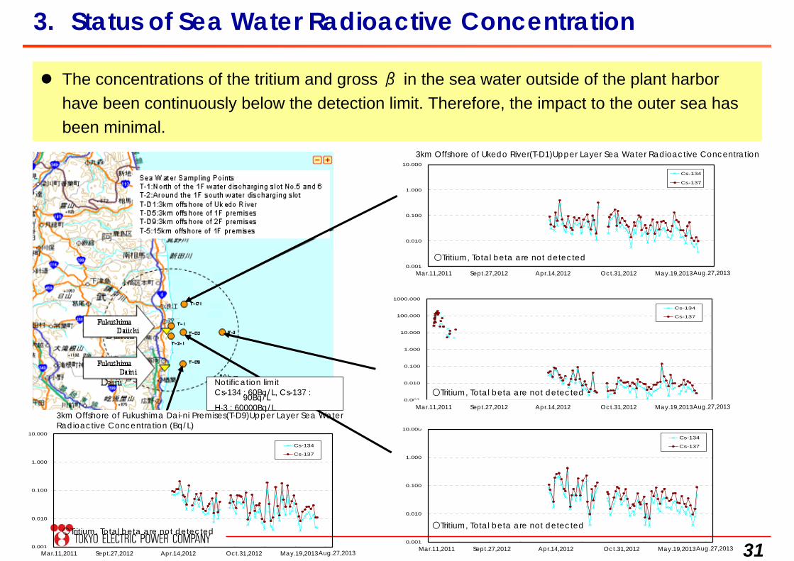
3. Status of Sea Water Radioactive Concentration
The concentrations of the tritium and gross β in the sea water outside of the plant harbor have been continuously below the detection limit. Therefore, the impact to the outer sea has been minimal.
請戸川沖合3km(T-D1) 上層 海水放射能濃度(Bq/L)
0.001
0.010
0.100
1.000
10.000
H23.3.11 H23.6.19 H23.9.27 H24.1.5 H24.4.14 H24.7.23 H24.10.31 H25.2.8 H25.5.19 H25.8.27
Cs-134
Cs-137
福島第一 敷地沖合15km(T-5) 上層 海水放射能濃度(Bq/L)
0.001
0.010
0.100
1.000
10.000
100.000
1000.000
H23.3.11 H23.6.19 H23.9.27 H24.1.5 H24.4.14 H24.7.23 H24.10.31 H25.2.8 H25.5.19 H25.8.27
Cs-134
Cs-137
福島第一 敷地沖合3km(T-D5) 上層 海水放射能濃度(Bq/L)
0.001
0.010
0.100
1.000
10.000
H23.3.11 H23.6.19 H23.9.27 H24.1.5 H24.4.14 H24.7.23 H24.10.31 H25.2.8 H25.5.19 H25.8.27
Cs-134
Cs-137
福島第二 敷地沖合3km(T-D9) 上層 海水放射能濃度(Bq/L)
0.001
0.010
0.100
1.000
10.000
H23.3.11 H23.6.19 H23.9.27 H24.1.5 H24.4.14 H24.7.23 H24.10.31 H25.2.8 H25.5.19 H25.8.27
Cs-134
Cs-137
3km Offshore of Ukedo River(T-D1)Upper Layer Sea Water Radioactive Concentration
Mar.11,2011 Sept.27,2012 Apr.14,2012 Oct.31,2012 May.19,2013Aug.27,2013
Mar.11,2011 Sept.27,2012 Apr.14,2012 Oct.31,2012 May.19,2013Aug.27,2013
Mar.11,2011 Sept.27,2012 Apr.14,2012 Oct.31,2012 May.19,2013Aug.27,2013Mar.11,2011 Sept.27,2012 Apr.14,2012 Oct.31,2012 May.19,2013Aug.27,2013
3km Offshore of Fukushima Dai-ni Premises(T-D9)Upper Layer Sea WaterRadioactive Concentration (Bq/L)
Notification limitCs-134 : 60Bq/L, Cs-137 : 90Bq/LH-3 : 60000Bq/L
○Tritium, Total beta are not detected○Tritium, Total beta are not detected
○Tritium, Total beta are not detected
○Tritium, Total beta are not detected

32
4. Mid/Long -Term Roadmap for Decommissioning
33
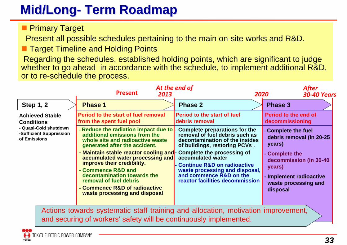
MidMid/L/Longong-- Term RoadmapTerm Roadmap
Step 1, 2
PresentAt the end of 2013
Achieved Stable Conditions- Quasi-Cold shutdown-Sufficient Suppression of Emissions
‐ Reduce the radiation impact due to additional emissions from the whole site and radioactive waste generated after the accident.
- Maintain stable reactor cooling and accumulated water processing and improve their credibility.
- Commence R&D and decontamination towards the removal of fuel debris
- Commence R&D of radioactive waste processing and disposal
Phase 1Period to the start of fuel removal from the spent fuel pool
2020After 30‐40 Years
Phase 3Phase 2Period to the start of fuel debris removal- Complete preparations for the
removal of fuel debris such as decontamination of the insides of buildings, restoring PCVs .
- Complete the processing of accumulated water
- Continue R&D on radioactive waste processing and disposal, and commence R&D on the reactor facilities decommission
‐ Complete the fuel debris removal (in 20-25 years)
- Complete the decommission (in 30-40 years)
- Implement radioactive waste processing and disposal
Period to the end of decommissioning
Actions towards systematic staff training and allocation, motivation improvement, and securing of workers’ safety will be continuously implemented.
Primary TargetPresent all possible schedules pertaining to the main on-site works and R&D. Target Timeline and Holding PointsRegarding the schedules, established holding points, which are significant to judge whether to go ahead in accordance with the schedule, to implement additional R&D, or to re-schedule the process.
34
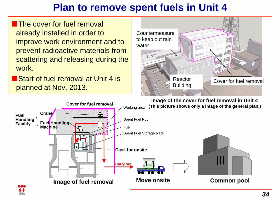
Plan to remove spent fuels in Unit 4■The cover for fuel removal
already installed in order to improve work environment and to prevent radioactive materials from scattering and releasing during the work.
■Start of fuel removal at Unit 4 is planned at Nov. 2013.
Image of the cover for fuel removal in Unit 4(This picture shows only a image of the general plan.)
原子炉建屋
雨水浸入対策
北
燃料取り出し用カバー Cover for fuel removal
Countermeasure to keep out rain water
Reactor Building
Common poolMove onsite
Spent Fuel Pool
Spent Fuel Storage Rack
Cover for fuel removalWorking area
Fuel
原子炉建屋
Cask for onsite
Carry out
Image of fuel removal
Crane
Fuel Handling Machine
Fuel Handling Facility
35
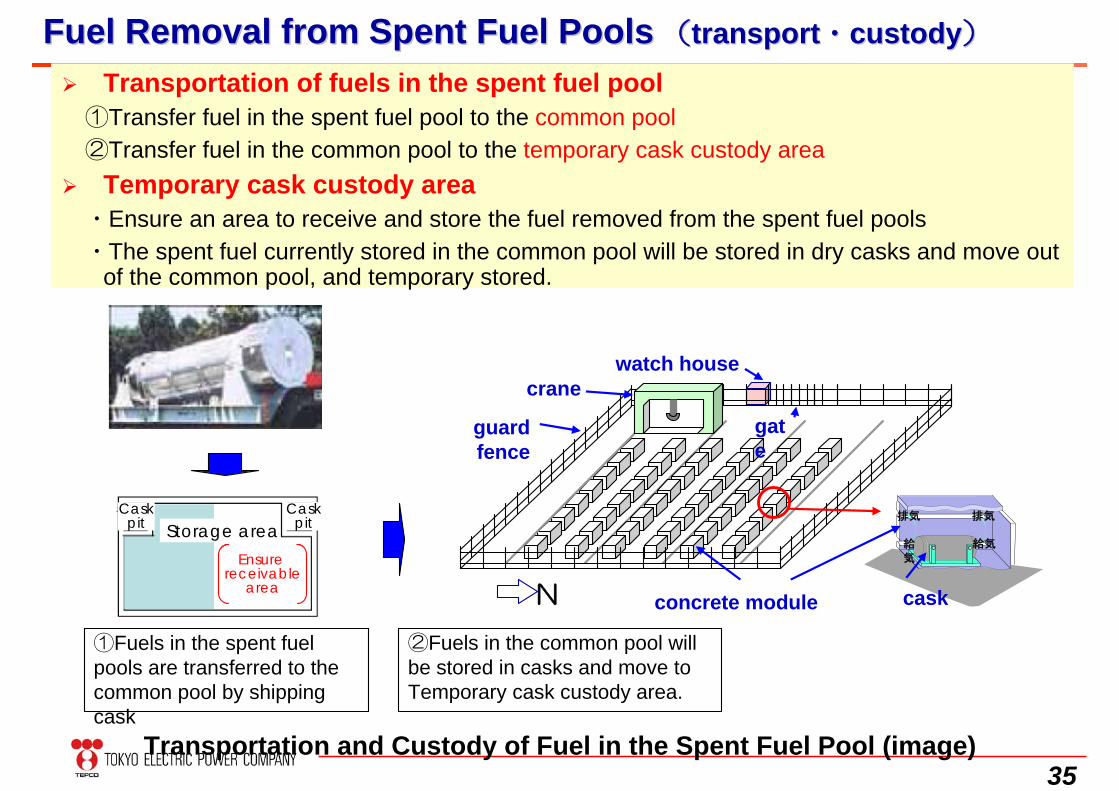
Fuel Removal from Spent Fuel PoolsFuel Removal from Spent Fuel Pools ((transporttransport・・custodycustody))
Transportation of fuels in the spent fuel pool①Transfer fuel in the spent fuel pool to the common pool②Transfer fuel in the common pool to the temporary cask custody area
Temporary cask custody area・Ensure an area to receive and store the fuel removed from the spent fuel pools・The spent fuel currently stored in the common pool will be stored in dry casks and move out
of the common pool, and temporary stored.
Transportation and Custody of Fuel in the Spent Fuel Pool (image)
①Fuels in the spent fuel pools are transferred to the common pool by shipping cask
②Fuels in the common pool will be stored in casks and move to Temporary cask custody area.
concrete module
給気
排気
給気
排気
crane
guard fence
gate
watch house
caskN
Caskpit
CaskpitStorage area
Ensure receivable
area
36
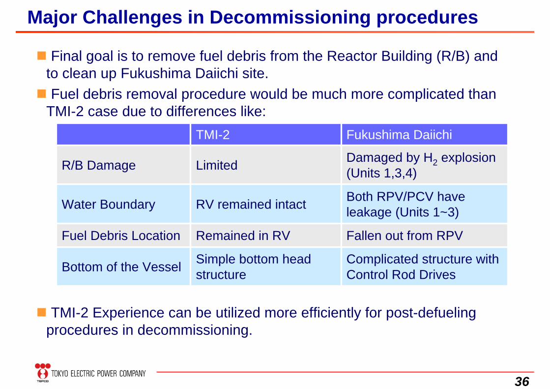
Major Challenges in Decommissioning procedures
Final goal is to remove fuel debris from the Reactor Building (R/B) and to clean up Fukushima Daiichi site. Fuel debris removal procedure would be much more complicated than
TMI-2 case due to differences like:
Both RPV/PCV have leakage (Units 1~3)RV remained intactWater Boundary
Complicated structure with Control Rod Drives
Simple bottom head structureBottom of the Vessel
Fallen out from RPVRemained in RVFuel Debris Location
Damaged by H2 explosion (Units 1,3,4)LimitedR/B Damage
Fukushima DaiichiTMI-2
TMI-2 Experience can be utilized more efficiently for post-defueling procedures in decommissioning.
37
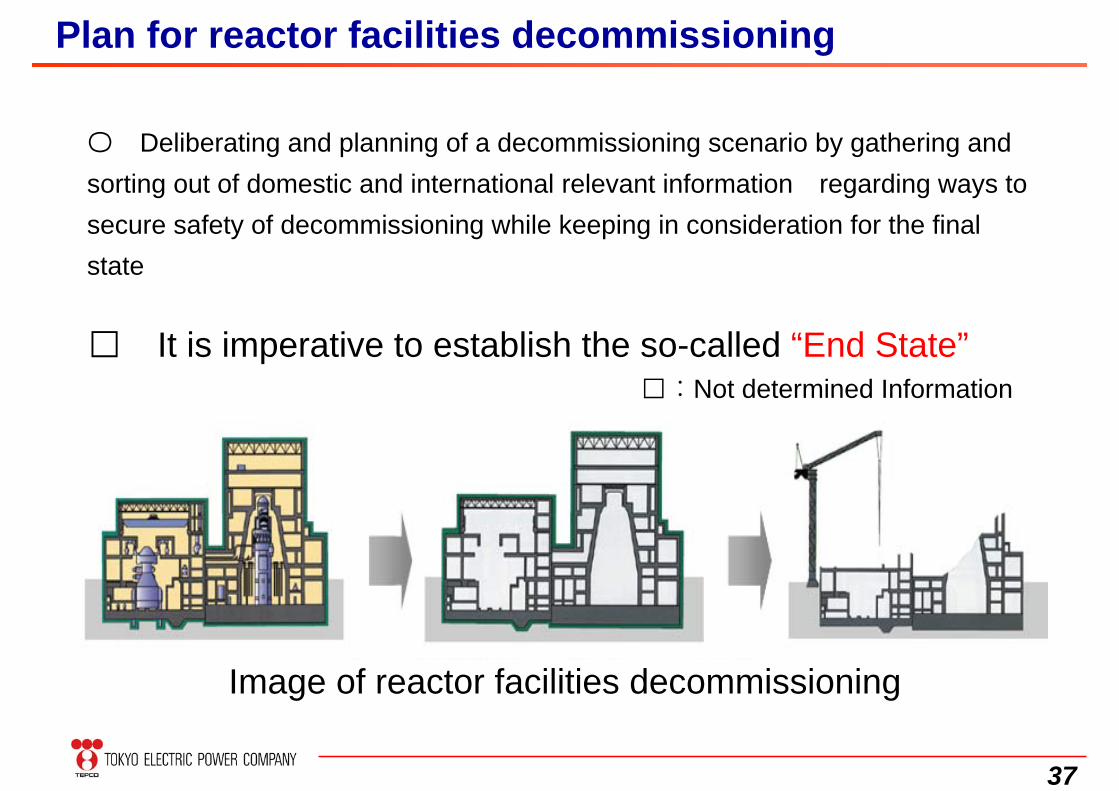
〇 Deliberating and planning of a decommissioning scenario by gathering and sorting out of domestic and international relevant information regarding ways to secure safety of decommissioning while keeping in consideration for the final state
□ It is imperative to establish the so-called “End State”□:Not determined Information
Plan for reactor facilities decommissioning
Image of reactor facilities decommissioning
38
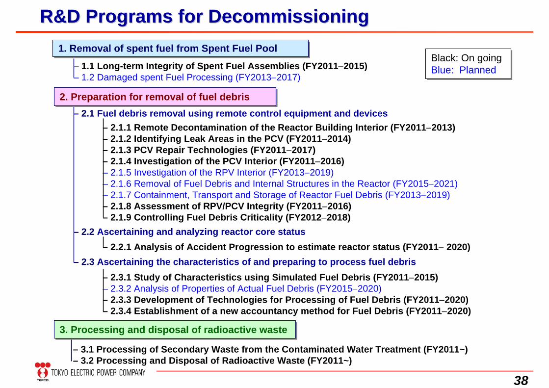
R&D Programs for DecommissioningR&D Programs for Decommissioning
– 1.1 Long-term Integrity of Spent Fuel Assemblies (FY20112015)– 1.2 Damaged spent Fuel Processing (FY20132017)
– 2.1.1 Remote Decontamination of the Reactor Building Interior (FY20112013)– 2.1.2 Identifying Leak Areas in the PCV (FY20112014)– 2.1.3 PCV Repair Technologies (FY20112017)– 2.1.4 Investigation of the PCV Interior (FY20112016)– 2.1.5 Investigation of the RPV Interior (FY20132019)– 2.1.6 Removal of Fuel Debris and Internal Structures in the Reactor (FY20152021)– 2.1.7 Containment, Transport and Storage of Reactor Fuel Debris (FY20132019)– 2.1.8 Assessment of RPV/PCV Integrity (FY20112016)– 2.1.9 Controlling Fuel Debris Criticality (FY20122018)
– 2.2.1 Analysis of Accident Progression to estimate reactor status (FY2011 2020)
– 2.3.1 Study of Characteristics using Simulated Fuel Debris (FY20112015)– 2.3.2 Analysis of Properties of Actual Fuel Debris (FY20152020)– 2.3.3 Development of Technologies for Processing of Fuel Debris (FY20112020)– 2.3.4 Establishment of a new accountancy method for Fuel Debris (FY20112020)
– 2.1 Fuel debris removal using remote control equipment and devices
– 2.2 Ascertaining and analyzing reactor core status
– 2.3 Ascertaining the characteristics of and preparing to process fuel debris
– 3.1 Processing of Secondary Waste from the Contaminated Water Treatment (FY2011~)– 3.2 Processing and Disposal of Radioactive Waste (FY2011~)
1. Removal of spent fuel from Spent Fuel Pool1. Removal of spent fuel from Spent Fuel Pool
2. Preparation for removal of fuel debris2. Preparation for removal of fuel debris
3. Processing and disposal of radioactive waste3. Processing and disposal of radioactive waste
Black: On going Blue: PlannedBlack: On going Blue: Planned
39
5. Long-Term Process In Preparation ForFuel Debris Removal
40
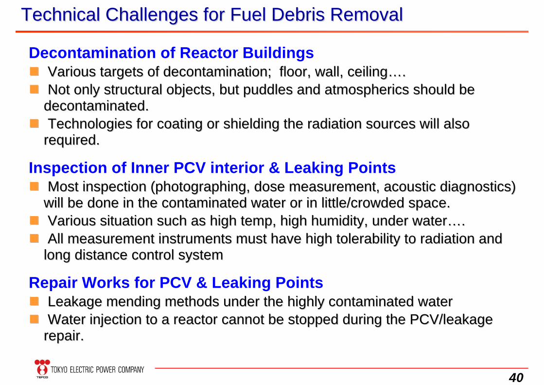
Decontamination of Reactor Buildings Various targets of decontamination; floor, wall, ceilingVarious targets of decontamination; floor, wall, ceiling…….. Not only structural objects, but puddles and atmospherics shoulNot only structural objects, but puddles and atmospherics should be d be
decontaminated.decontaminated. Technologies for coating or shielding the radiation sources wilTechnologies for coating or shielding the radiation sources will also l also
required.required.
Inspection of Inner PCV interior & Leaking Points Most inspection (photographing, dose measurement, acoustic diagMost inspection (photographing, dose measurement, acoustic diagnostics) nostics)
will be done in the contaminated water or in little/crowded spacwill be done in the contaminated water or in little/crowded space.e. Various situation such as high temp, high humidity, under waterVarious situation such as high temp, high humidity, under water…….. All measurement instruments must have high tolerability to radiAll measurement instruments must have high tolerability to radiation and ation and
long distance control systemlong distance control system
Repair Works for PCV & Leaking Points Leakage mending methods under the highly contaminated water Leakage mending methods under the highly contaminated water Water injection to a reactor cannot be stopped during the PCV/lWater injection to a reactor cannot be stopped during the PCV/leakage eakage
repair.repair.
Technical Challenges for Fuel Debris RemovalTechnical Challenges for Fuel Debris Removal
41
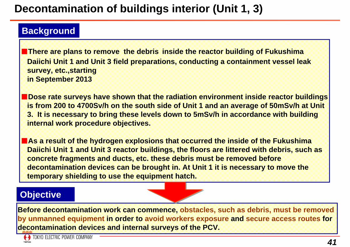
■There are plans to remove the debris inside the reactor building of FukushimaDaiichi Unit 1 and Unit 3 field preparations, conducting a containment vessel leaksurvey, etc.,startingin September 2013
■Dose rate surveys have shown that the radiation environment inside reactor buildingsis from 200 to 4700Sv/h on the south side of Unit 1 and an average of 50mSv/h at Unit3. It is necessary to bring these levels down to 5mSv/h in accordance with buildinginternal work procedure objectives.
■As a result of the hydrogen explosions that occurred the inside of the FukushimaDaiichi Unit 1 and Unit 3 reactor buildings, the floors are littered with debris, such asconcrete fragments and ducts, etc. these debris must be removed beforedecontamination devices can be brought in. At Unit 1 it is necessary to move thetemporary shielding to use the equipment hatch.
Before decontamination work can commence, obstacles, such as debris, must be removed by unmanned equipment in order to avoid workers exposure and secure access routes for decontamination devices and internal surveys of the PCV.
Decontamination of buildings interior (Unit 1, 3)
Background
Objective
42
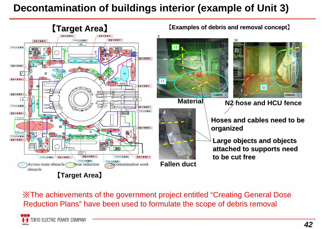
【【Target AreaTarget Area】】
N2 hose and HCU fence
Fallen duct【Target Area】
【【Examples of debris and removal conceptExamples of debris and removal concept】】
※The achievements of the government project entitled “Creating General Dose Reduction Plans” have been used to formulate the scope of debris removal
Access route obstacle Dose reduction decontamination work obstacle
Material
Large objects and objects Large objects and objects attached to supports need attached to supports need to be cut freeto be cut free
Hoses and cables need to be Hoses and cables need to be organizedorganized
Decontamination of buildings interior (example of Unit 3)
43
Step 1: Reactor Building DecontaminationStep 1: Reactor Building Decontamination
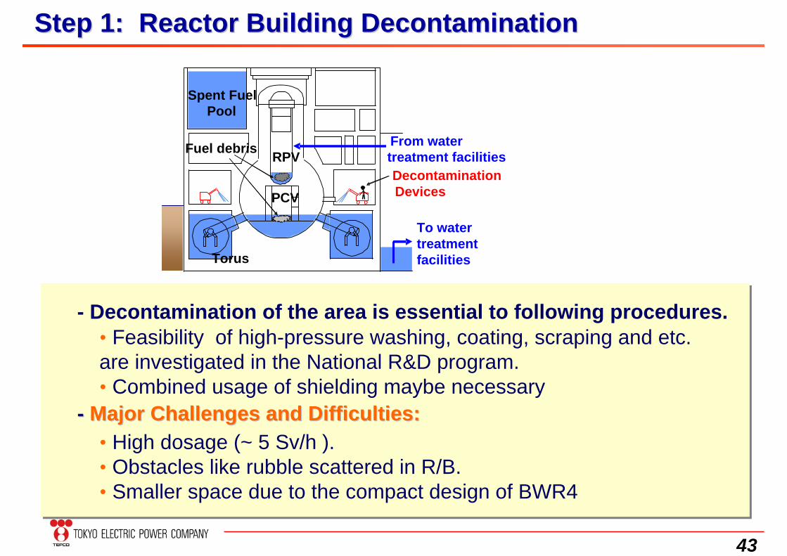
• Feasibility of high-pressure washing, coating, scraping and etc. are investigated in the National R&D program.• Combined usage of shielding maybe necessary
- Decontamination of the area is essential to following procedures.
• High dosage (~ 5 Sv/h ).• Obstacles like rubble scattered in R/B.• Smaller space due to the compact design of BWR4
From watertreatment facilitiesRPV
Spent FuelPool
Torus
DecontaminationDevices
Fuel debris
PCV
To water treatment facilities
-- Major Challenges and Difficulties:Major Challenges and Difficulties:
44
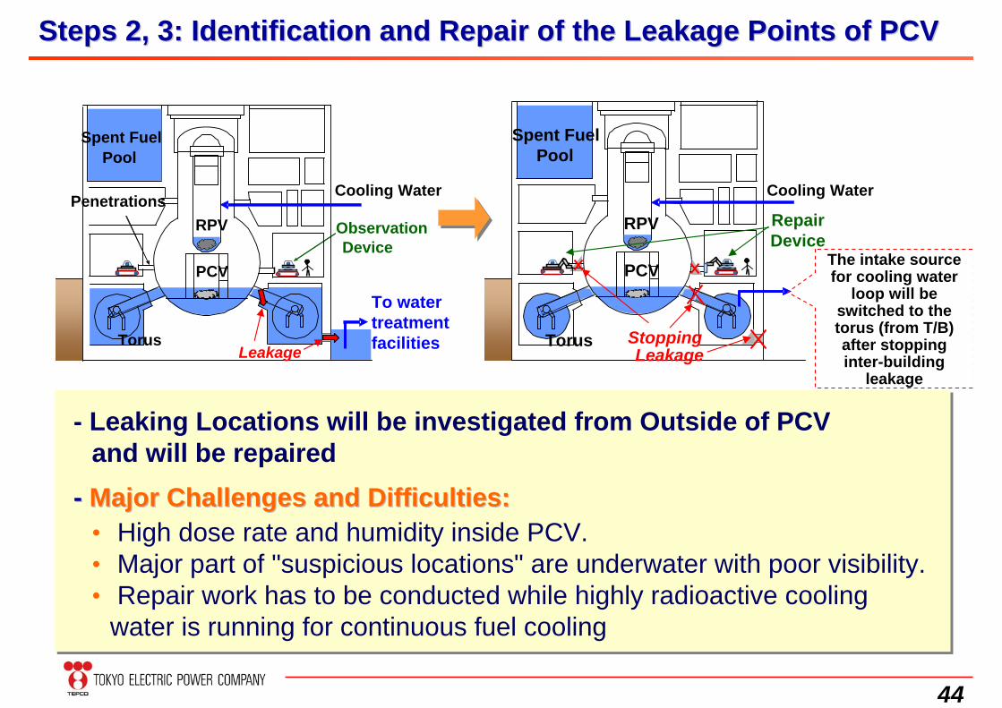
Steps 2, 3: Identification and Repair of the Leakage Points of PSteps 2, 3: Identification and Repair of the Leakage Points of PCVCV
-- Major Challenges and Difficulties:Major Challenges and Difficulties:• High dose rate and humidity inside PCV.• Major part of "suspicious locations" are underwater with poor visibility.• Repair work has to be conducted while highly radioactive cooling
water is running for continuous fuel cooling
Spent FuelPool
TorusLeakage
ObservationDevice
PCV
RPVPenetrations
Cooling Water
Torus
Repair Device
RPV
PCV
StoppingLeakage
Spent FuelPool
- Leaking Locations will be investigated from Outside of PCV and will be repaired
The intake source for cooling water
loop will be switched to the torus (from T/B) after stopping inter-building
leakage
To water treatment facilities
Cooling Water
45
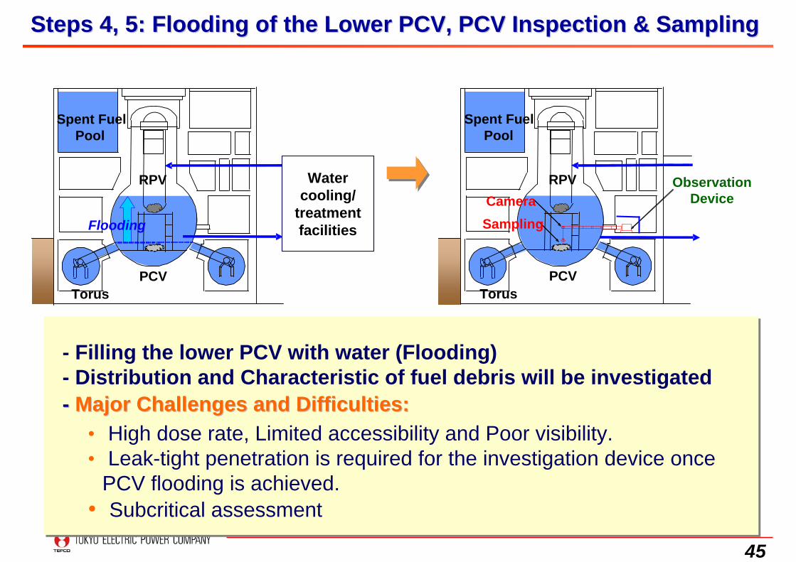
Steps 4, 5: Flooding of the Lower PCV, PCV Inspection & SamplingSteps 4, 5: Flooding of the Lower PCV, PCV Inspection & Sampling
- Filling the lower PCV with water (Flooding)- Distribution and Characteristic of fuel debris will be investigated
• High dose rate, Limited accessibility and Poor visibility.• Leak-tight penetration is required for the investigation device once
PCV flooding is achieved.• Subcritical assessment
Torus
Spent FuelPool
RPV
PCV
Flooding
Water cooling/
treatment facilities
Torus
Spent FuelPool
CameraObservation
Device
Sampling
RPV
PCV
-- Major Challenges and Difficulties:Major Challenges and Difficulties:
46
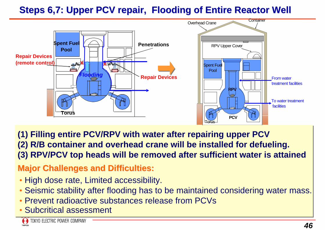
Steps 6,7: Upper PCV repair, Flooding of Entire Reactor WellSteps 6,7: Upper PCV repair, Flooding of Entire Reactor Well
Repair Devices(remote control)
Repair Devices
Torus
Spent FuelPool
Penetrations
Flooding
(1) Filling entire PCV/RPV with water after repairing upper PCV(2) R/B container and overhead crane will be installed for defueling.(3) RPV/PCV top heads will be removed after sufficient water is attained
• High dose rate, Limited accessibility.• Seismic stability after flooding has to be maintained considering water mass. • Prevent radioactive substances release from PCVs• Subcritical assessment
Major Challenges and Difficulties:Major Challenges and Difficulties:
ContainerOverhead Crane
Spent FuelPool
PCV
RPV Upper Cover
Torus
From watertreatment facilities
To water treatment facilities
RPV
47
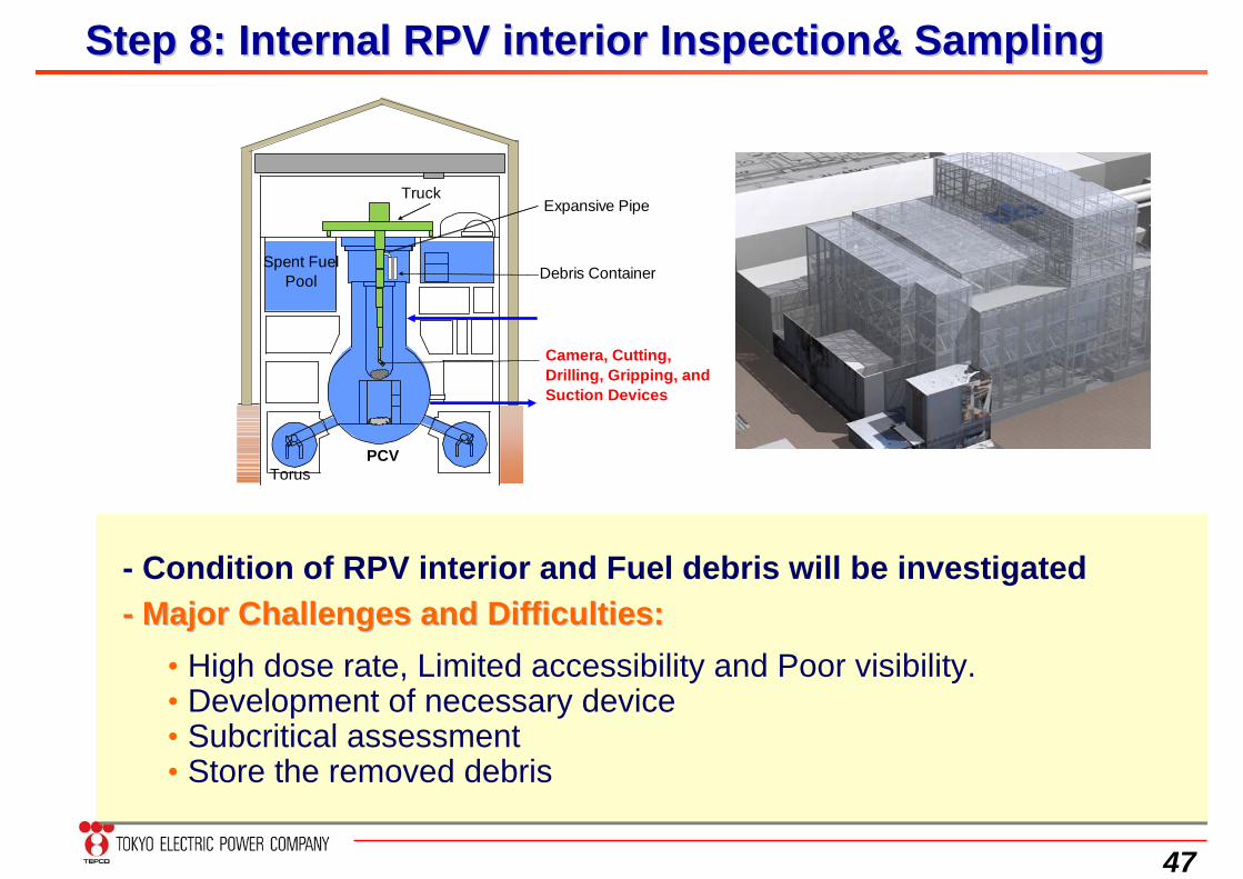
Step 8: Internal RPV interior Inspection& SamplingStep 8: Internal RPV interior Inspection& Sampling
Camera, Cutting,Drilling, Gripping, andSuction Devices
Spent FuelPool
PCV
TruckExpansive Pipe
Debris Container
Torus
- Condition of RPV interior and Fuel debris will be investigated
• High dose rate, Limited accessibility and Poor visibility.• Development of necessary device• Subcritical assessment• Store the removed debris
-- Major Challenges and Difficulties:Major Challenges and Difficulties:
48
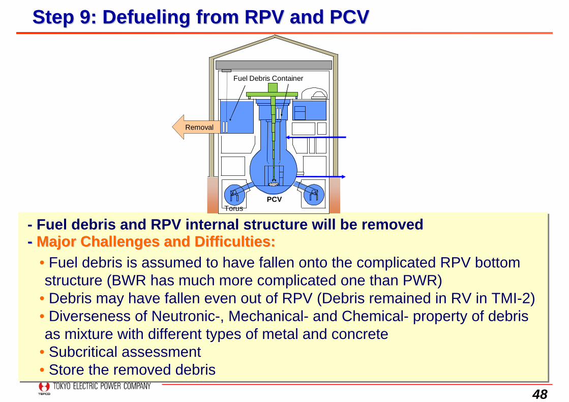
Step 9: Defueling from RPV and PCVStep 9: Defueling from RPV and PCV
PCV
Fuel Debris Container
Removal
Torus
- Fuel debris and RPV internal structure will be removed
• Fuel debris is assumed to have fallen onto the complicated RPV bottom structure (BWR has much more complicated one than PWR)
• Debris may have fallen even out of RPV (Debris remained in RV in TMI-2)• Diverseness of Neutronic-, Mechanical- and Chemical- property of debris as mixture with different types of metal and concrete
• Subcritical assessment• Store the removed debris
-- Major Challenges and Difficulties:Major Challenges and Difficulties:
49
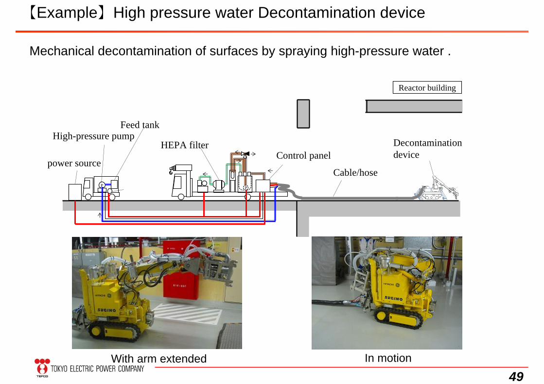
【Example】High pressure water Decontamination device
Mechanical decontamination of surfaces by spraying high-pressure water .
With arm extended
Reactor building
P
HEPA filter
Feed tankHigh-pressure pump
power source
Decontamination device
Cable/hoseP
Control panel
In motion
50
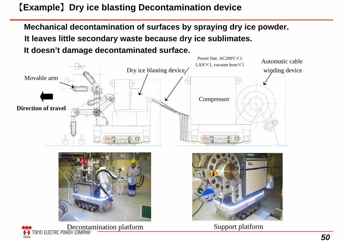
【Example】Dry ice blasting Decontamination device
Mechanical decontamination of surfaces by spraying dry ice powder.It leaves little secondary waste because dry ice sublimates.It doesn’t damage decontaminated surface.
Decontamination platform Support platform
Direction of travelCompressor
Power line: AC200V×1LAN×1, vacuum hose×1
Dry ice blasting deviceMovable arm
Automatic cable winding device
51
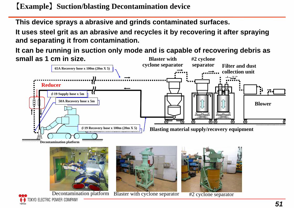
【Example】Suction/blasting Decontamination device
This device sprays a abrasive and grinds contaminated surfaces.It uses steel grit as an abrasive and recycles it by recovering it after spraying and separating it from contamination.It can be running in suction only mode and is capable of recovering debris as small as 1 cm in size.
65A回収ホース×100m(20m×5本)
φ19供給ホース×5m
サイクロンセパレータ付ブラスト機
ブラスト材供給/回収設備
ブロア50A回収ホース×5m
φ19供給ホース×100m(20m×5本)
第2サイクロン
セパレータ
フィルタ集塵
ユニット
除染台車
レデューサ
65A回収ホース×100m(20m×5本)
φ19供給ホース×5m
サイクロンセパレータ付ブラスト機
ブラスト材供給/回収設備
ブロア50A回収ホース×5m
φ19供給ホース×100m(20m×5本)
第2サイクロン
セパレータ
フィルタ集塵
ユニット
除染台車
レデューサ
Decontamination platform Blaster with cyclone separator #2 cyclone separator
65A Recovery hose x 100m (20m X 5)
φ19 Recovery hose x 100m (20m X 5)
Reducerφ19 Supply hose x 5m
50A Recovery hose x 5m
Decontamination platform
Blaster with cyclone separator
#2 cyclone separator Filter and dust
collection unit
Blasting material supply/recovery equipment
Blower
52
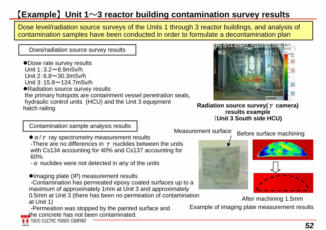
【Example】Unit 1~3 reactor building contamination survey resultsDose level/radiation source surveys of the Units 1 through 3 reactor buildings, and analysis of contamination samples have been conducted in order to formulate a decontamination plan
Does/radiation source survey results
Dose rate survey resultsUnit 1:3.2~8.9mSv/hUnit 2:6.8~30.3mSv/hUnit 3:15.8~124.7mSv/hRadiation source survey resultsthe primary hotspots are containment vessel penetration seals,hydraulic control units (HCU) and the Unit 3 equipment hatch railing Radiation source survey(γ camera)
results example(Unit 3 South side HCU)
Contamination sample analysis results
Example of imaging plate measurement results
Measurement surface Before surface machining
After machining 1.5mm
α/γ ray spectrometry measurement results-There are no differences in γ nuclides between the unitswith Cs134 accounting for 40% and Cs137 accounting for60%.-α nuclides were not detected in any of the units
Imaging plate (IP) measurement results-Contamination has permeated epoxy coated surfaces up to a maximum of approximately 1mm at Unit 3 and approximately 0.5mm at Unit 3 (there has been no permeation of contamination at Unit 1)-Permeation was stopped by the painted surface and the concrete has not been contaminated.
53
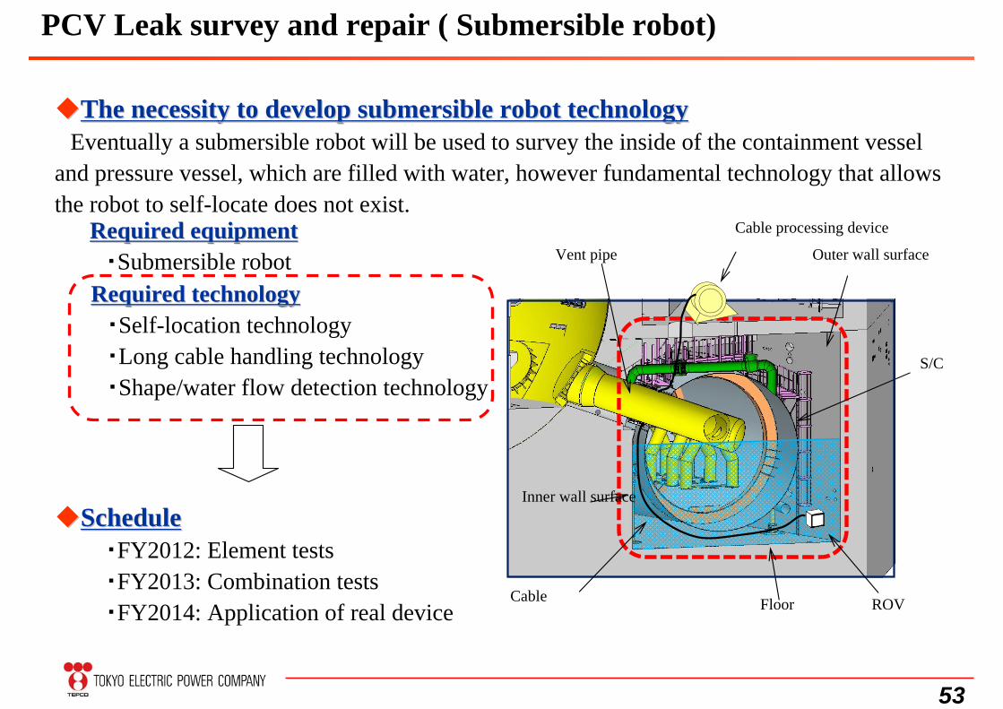
The necessity to develop submersible robot technologyThe necessity to develop submersible robot technologyEventually a submersible robot will be used to survey the inside of the containment vessel
and pressure vessel, which are filled with water, however fundamental technology that allows the robot to self-locate does not exist.
Required equipmentRequired equipment・Submersible robot
Required technologyRequired technology・Self-location technology・Long cable handling technology・Shape/water flow detection technology
ScheduleSchedule・FY2012: Element tests・FY2013: Combination tests・FY2014: Application of real device ROV
Outer wall surface
Inner wall surface
Floor
Cable processing device
Cable
Vent pipe
S/C
PCV Leak survey and repair ( Submersible robot)
54
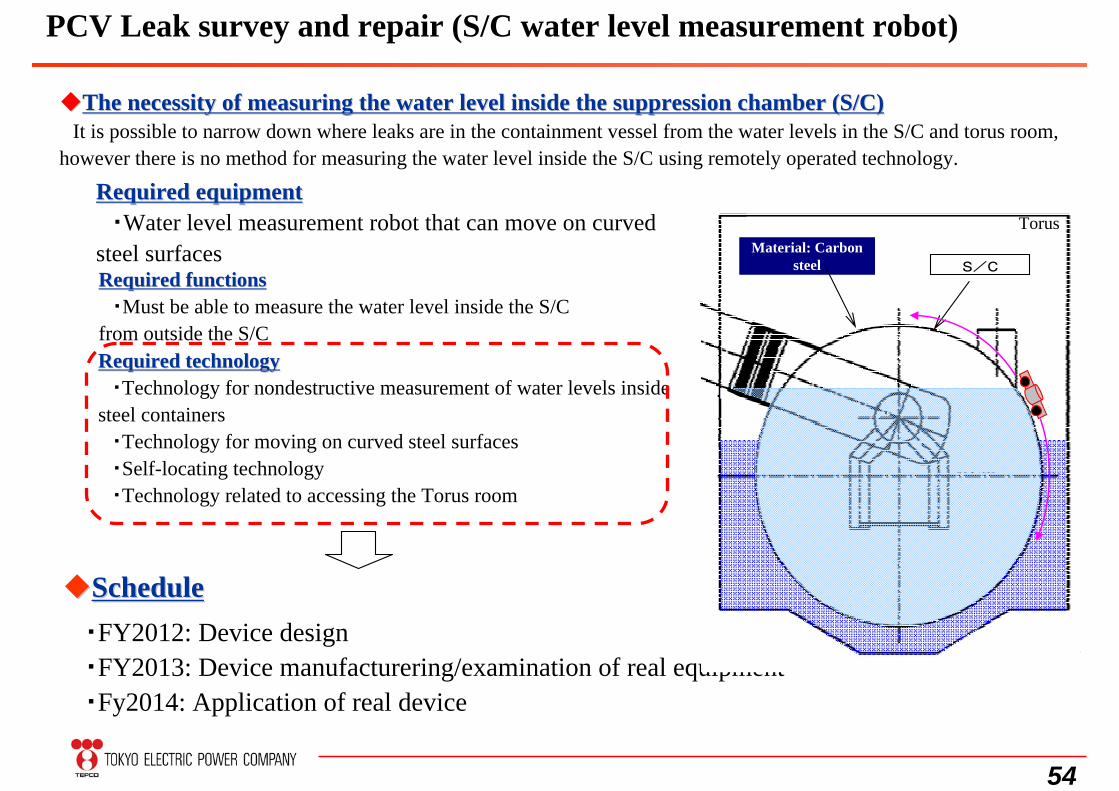
Required technologyRequired technology・Technology for nondestructive measurement of water levels inside
steel containers・Technology for moving on curved steel surfaces・Self-locating technology・Technology related to accessing the Torus room
ScheduleSchedule・FY2012: Device design・FY2013: Device manufacturering/examination of real equipment・Fy2014: Application of real device
The necessity of measuring the water level inside the suppressioThe necessity of measuring the water level inside the suppression chamber (S/C)n chamber (S/C)It is possible to narrow down where leaks are in the containment vessel from the water levels in the S/C and torus room,
however there is no method for measuring the water level inside the S/C using remotely operated technology.
Required equipmentRequired equipment・Water level measurement robot that can move on curved
steel surfacesRequired functionsRequired functions
・Must be able to measure the water level inside the S/C from outside the S/C
TorusMaterial: Carbon
steel S/C
PCV Leak survey and repair (S/C water level measurement robot)
55
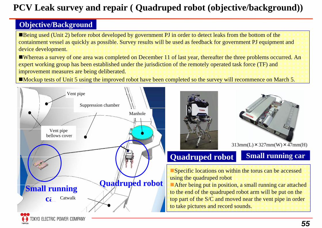
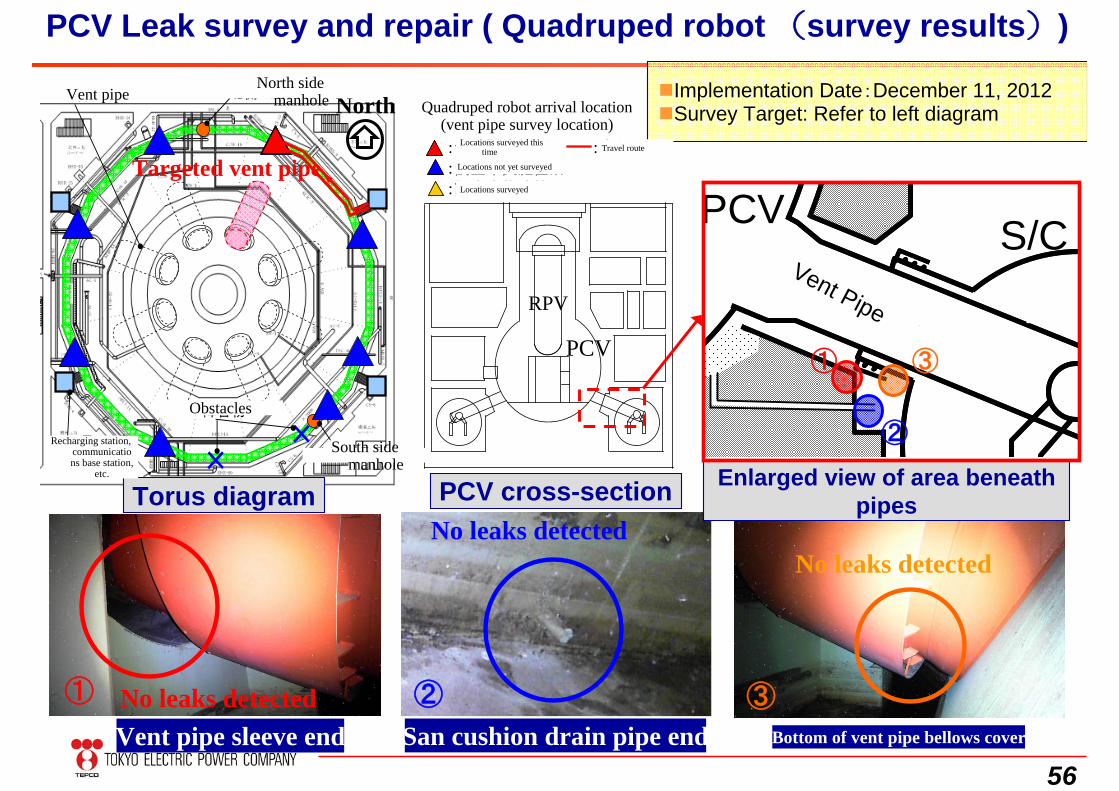
Objective/Background
Specific locations on within the torus can be accessed using the quadruped robotAfter being put in position, a small running car attached to the end of the quadruped robot arm will be put on the top part of the S/C and moved near the vent pipe in order to take pictures and record sounds.
Quadruped robot Small running car313mm(L)×327mm(W)×47mm(H)
サプレッションチェンバ(S/C)
キャットウォーク
マンホール
ベント管
ベント管ベローズカバー
Quadruped robotSmall running car
Being used (Unit 2) before robot developed by government PJ in order to detect leaks from the bottom of the containment vessel as quickly as possible. Survey results will be used as feedback for government PJ equipment and device development.Whereas a survey of one area was completed on December 11 of last year, thereafter the three problems occurred. An expert working group has been established under the jurisdiction of the remotely operated task force (TF) and improvement measures are being deliberated.Mockup tests of Unit 5 using the improved robot have been completed so the survey will recommence on March 5.
PCV Leak survey and repair ( Quadruped robot (objective/background))
Vent pipe
Vent pipebellows cover
Suppression chamber
Manhole
Catwalk
56
S/ベント管S/ベント管
Vent pipe sleeve end San cushion drain pipe end Bottom of vent pipe bellows cover
Enlarged view of area beneath pipes
北側マンホール
南側マンホール××
障害物
ベント管
充電台、通信基地他
北側マンホール
南側マンホール××
障害物
ベント管 北側マンホール
南側マンホール××
障害物
ベント管
充電台、通信基地他
Torus diagram PCV cross-section
① ② ③
PCV
① ③
②
S/CRPV
PCV
4足歩行ロボット到達位置
(ベント管調査位置):今回調査箇所 :歩行ルート:調査未実施箇所:調査実施済箇所
4足歩行ロボット到達位置
(ベント管調査位置):今回調査箇所 :歩行ルート:調査未実施箇所:調査実施済箇所
Targeted vent pipe
North
No leaks detected
No leaks detectedNo leaks detected
PCV Leak survey and repair ( Quadruped robot (survey results))
Implementation Date:December 11, 2012Survey Target: Refer to left diagram
North side manholeVent pipe
Recharging station, communications base station,
etc.
Obstacles
South side manhole
Quadruped robot arrival location(vent pipe survey location)
Locations surveyed this time Travel route
Locations not yet surveyed
Locations surveyed
Vent Pipe
57
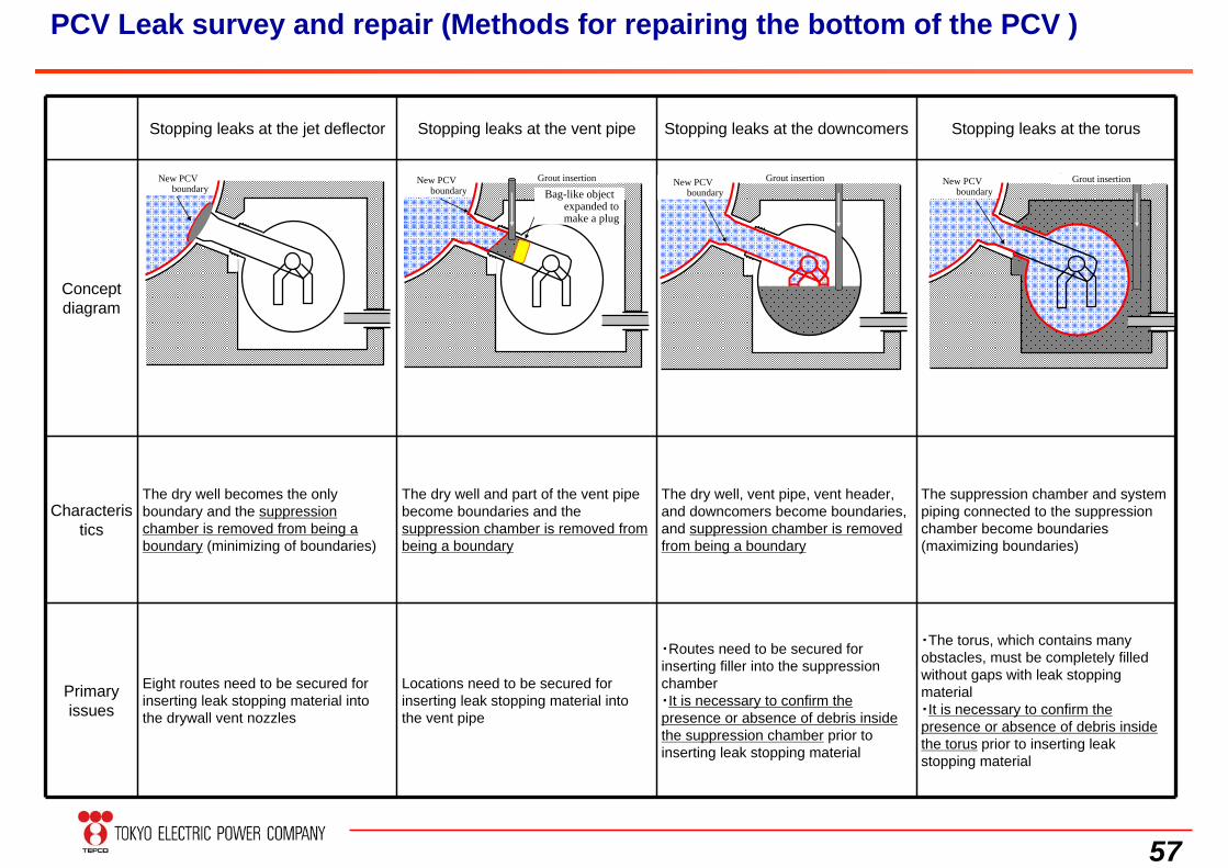
Stopping leaks at the jet deflector Stopping leaks at the vent pipe Stopping leaks at the downcomers Stopping leaks at the torus
Concept diagram
Characteristics
The dry well becomes the only boundary and the suppression chamber is removed from being a boundary (minimizing of boundaries)
The dry well and part of the vent pipe become boundaries and the suppression chamber is removed from being a boundary
The dry well, vent pipe, vent header, and downcomers become boundaries, and suppression chamber is removed from being a boundary
The suppression chamber and system piping connected to the suppression chamber become boundaries (maximizing boundaries)
Primary issues
Eight routes need to be secured for inserting leak stopping material into the drywall vent nozzles
Locations need to be secured for inserting leak stopping material into the vent pipe
・Routes need to be secured for inserting filler into the suppression chamber・It is necessary to confirm the presence or absence of debris inside the suppression chamber prior to inserting leak stopping material
・The torus, which contains many obstacles, must be completely filled without gaps with leak stopping material・It is necessary to confirm the presence or absence of debris inside the torus prior to inserting leak stopping material
新たなPCVバウンダリ
グラウト等の注入新たなPCVバウンダリ
袋のようなものを膨らませて栓をする
グラウト等の注入新たなPCVバウンダリ
グラウト等の注入新たなPCVバウンダリ
PCV Leak survey and repair (Methods for repairing the bottom of the PCV )
New PCV boundary
New PCV boundary
New PCV boundary
New PCV boundary
Grout insertion Grout insertion Grout insertionBag-like object
expanded to make a plug
58
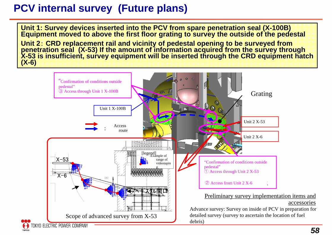
PCV internal survey (Future plans)
Unit 1: Survey devices inserted into the PCV from spare penetration seal (X-100B) Equipment moved to above the first floor grating to survey the outside of the pedestal Unit 2: CRD replacement rail and vicinity of pedestal opening to be surveyed from penetration seal (X-53) If the amount of information acquired from the survey through X-53 is insufficient, survey equipment will be inserted through the CRD equipment hatch (X-6)
:アクセスルート:アクセスルート:アクセスルート
「X-6~ペデスタル開口までの状況確認」①2号機 X-53からのアクセス②2号機 X-6からのアクセス
グレーチング
事前調査実施項目とアクセスルート
2号機 X-53
2号機 X-6
1号機_X100B
「ペデスタル外の状況確認」③1号機 X-100Bからのアクセス
【凡例】
:映像取得範囲の例
X-53
X-6
ペデスタル開口
X-53からの事前調査範囲
Advance survey: Survey on inside of PCV in preparation for detailed survey (survey to ascertain the location of fuel debris)
“Confirmation of conditions outside pedestal”③ Access through Unit 1 X-100B
“Confirmation of conditions outside pedestal”① Access through Unit 2 X-53
Access route
Unit 1 X-100B
Grating
Unit 2 X-53
Unit 2 X-6
② Access from Unit 2 X-6
Preliminary survey implementation items and accessories
Scope of advanced survey from X-53
[legend]:Example of
range of videotaping
59
6. Remaining Challenges for FuelDebris Retrieval
60
Torus Room
Recirc. Pipe
Suppression Chamber
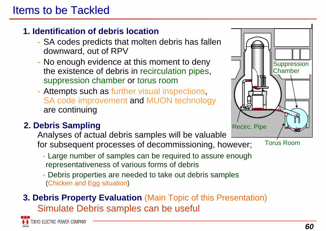
Items to be TackledItems to be Tackled
1. Identification of debris location
3. Debris Property Evaluation (Main Topic of this Presentation)Simulate Debris samples can be useful
- Large number of samples can be required to assure enough representativeness of various forms of debris
- Debris properties are needed to take out debris samples (Chicken and Egg situation)
- SA codes predicts that molten debris has fallen downward, out of RPV
- No enough evidence at this moment to deny the existence of debris in recirculation pipes, suppression chamber or torus room
- Attempts such as further visual inspections, SA code improvement and MUON technologyare continuing
Analyses of actual debris samples will be valuable for subsequent processes of decommissioning, however;
2. Debris Sampling
61
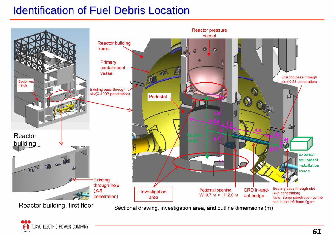
Identification of Fuel Debris LocationIdentification of Fuel Debris Location
62
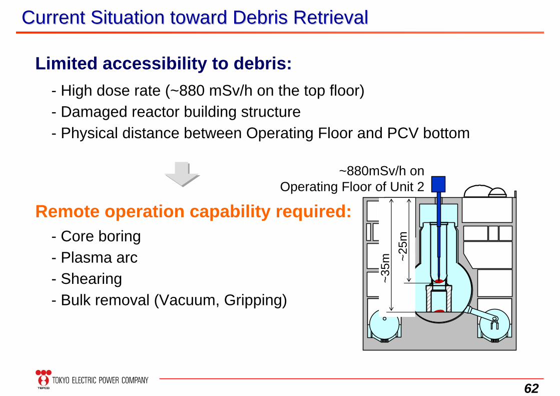
Current Situation toward Debris RetrievalCurrent Situation toward Debris Retrieval
Limited accessibility to debris:- High dose rate (~880 mSv/h on the top floor)- Damaged reactor building structure- Physical distance between Operating Floor and PCV bottom
~25m
~35m
Remote operation capability required:- Core boring- Plasma arc- Shearing- Bulk removal (Vacuum, Gripping)
~880mSv/h on Operating Floor of Unit 2
63
D/S Pit11419
0207
154
250
SFP
5244
44 85 146
127
84
81
99
128
59
55 78
77
80
57
83
6048
78
47
40 67 111
230
153
530
139
829506
376415401
173
356
13380
880
783
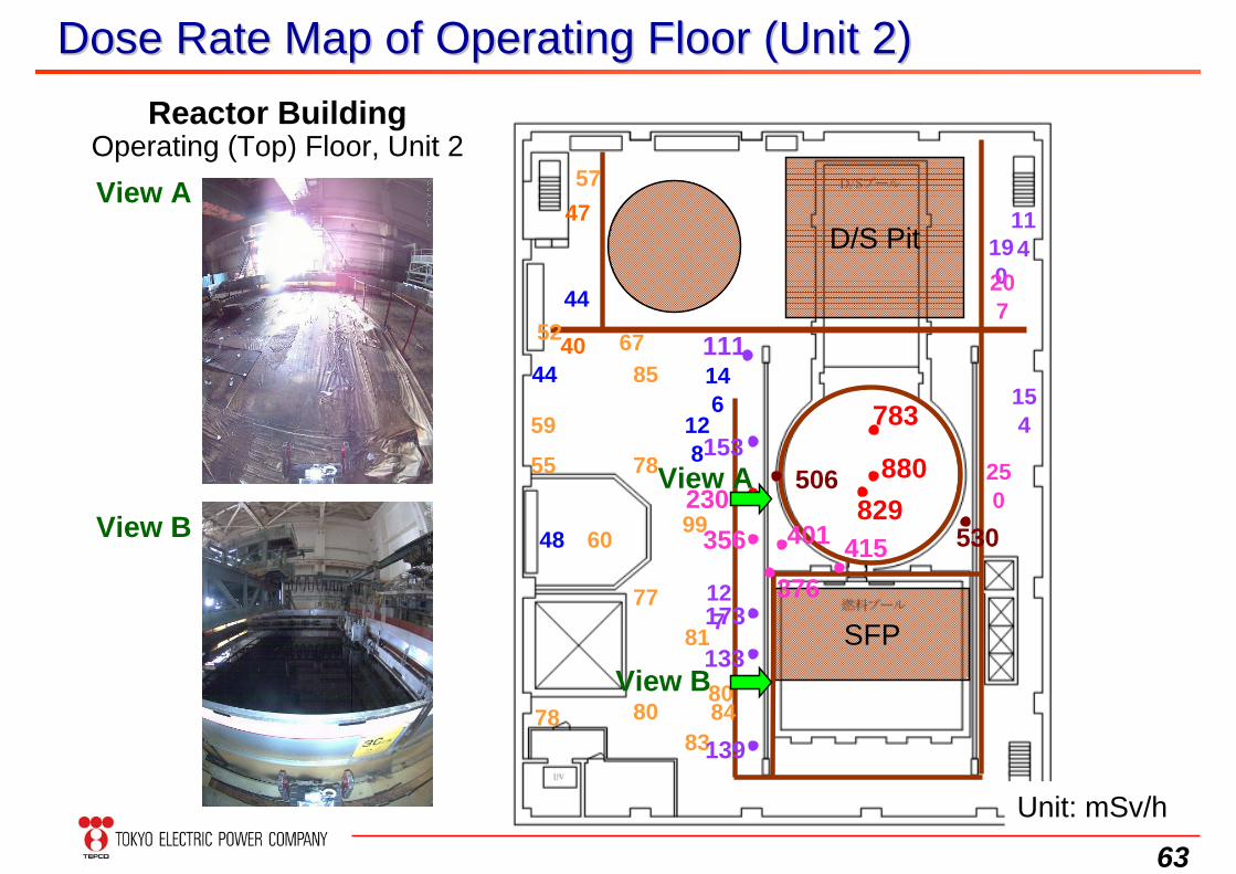
Reactor BuildingOperating (Top) Floor, Unit 2
View A
View B
View A
View B
Dose Rate Map of Operating Floor (Unit 2)Dose Rate Map of Operating Floor (Unit 2)
Unit: mSv/h
64
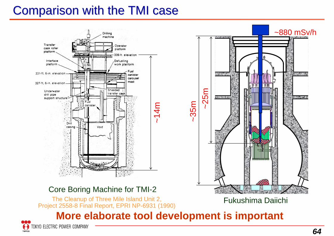
Comparison with the TMI caseComparison with the TMI case
~14m
Core Boring Machine for TMI-2
~25m
~35m
More elaborate tool development is importantFukushima Daiichi
~880 mSv/h
The Cleanup of Three Mile Island Unit 2, Project 2558-8 Final Report, EPRI NP-6931 (1990)
65
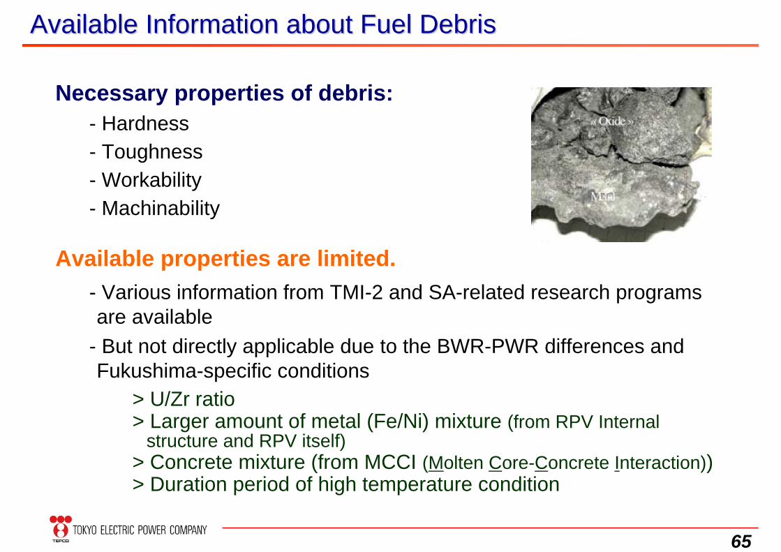
Available Information about Fuel DebrisAvailable Information about Fuel Debris
Necessary properties of debris:- Hardness- Toughness- Workability- Machinability
Available properties are limited.- Various information from TMI-2 and SA-related research programs are available
- But not directly applicable due to the BWR-PWR differences and Fukushima-specific conditions
> U/Zr ratio> Larger amount of metal (Fe/Ni) mixture (from RPV Internal
structure and RPV itself) > Concrete mixture (from MCCI (Molten Core-Concrete Interaction))> Duration period of high temperature condition
66
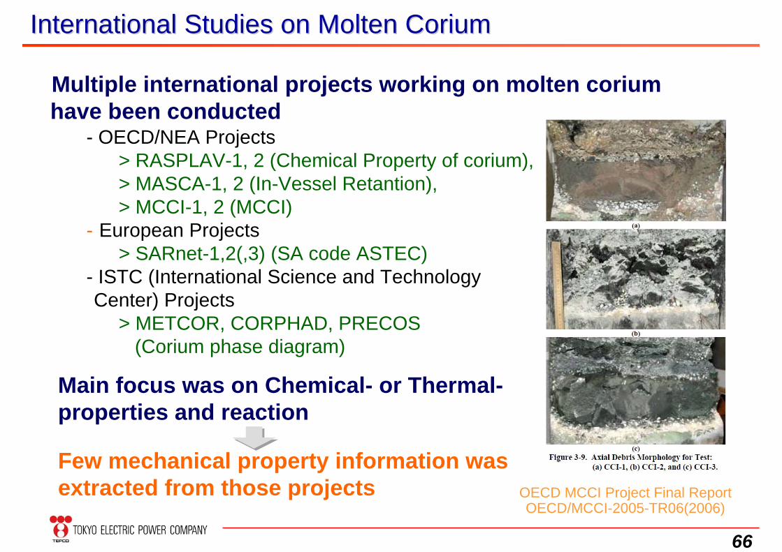
International Studies on Molten CoriumInternational Studies on Molten Corium
Multiple international projects working on molten corium have been conducted
- OECD/NEA Projects> RASPLAV-1, 2 (Chemical Property of corium), > MASCA-1, 2 (In-Vessel Retantion), > MCCI-1, 2 (MCCI)
- European Projects > SARnet-1,2(,3) (SA code ASTEC)
- ISTC (International Science and Technology Center) Projects
> METCOR, CORPHAD, PRECOS(Corium phase diagram)
Few mechanical property information was extracted from those projects
Main focus was on Chemical- or Thermal-properties and reaction
OECD MCCI Project Final ReportOECD/MCCI-2005-TR06(2006)
67
Examples of Lessons learned from Foreign OrganizationExamples of Lessons learned from Foreign Organization
Integrated Waste Management
Fukushima Daiichi(1F)-specific waste management strategy is needed. It has to be regarded as key principles in designing decommissioning procedures. The waste management strategy should include not only long-
term storage but also re-using and recycling of materials. The facility and site plans should be established considering their prioritization. Precise estimations of the future waste generation is important in
long-term decommissioning planning. Close communication between decommissioning process management- and waste management-teams is indispensable.
68
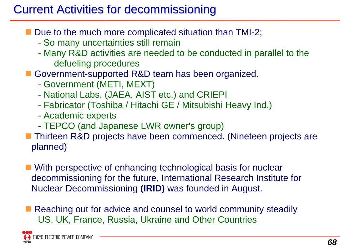
Current Activities for decommissioningCurrent Activities for decommissioning
Due to the much more complicated situation than TMI-2;- So many uncertainties still remain- Many R&D activities are needed to be conducted in parallel to the
defueling procedures Government-supported R&D team has been organized.
- Government (METI, MEXT)- National Labs. (JAEA, AIST etc.) and CRIEPI - Fabricator (Toshiba / Hitachi GE / Mitsubishi Heavy Ind.)- Academic experts- TEPCO (and Japanese LWR owner's group)
Thirteen R&D projects have been commenced. (Nineteen projects areplanned)
With perspective of enhancing technological basis for nucleardecommissioning for the future, International Research Institute for Nuclear Decommissioning (IRID) was founded in August.
Reaching out for advice and counsel to world community steadilyUS, UK, France, Russia, Ukraine and Other Countries
69
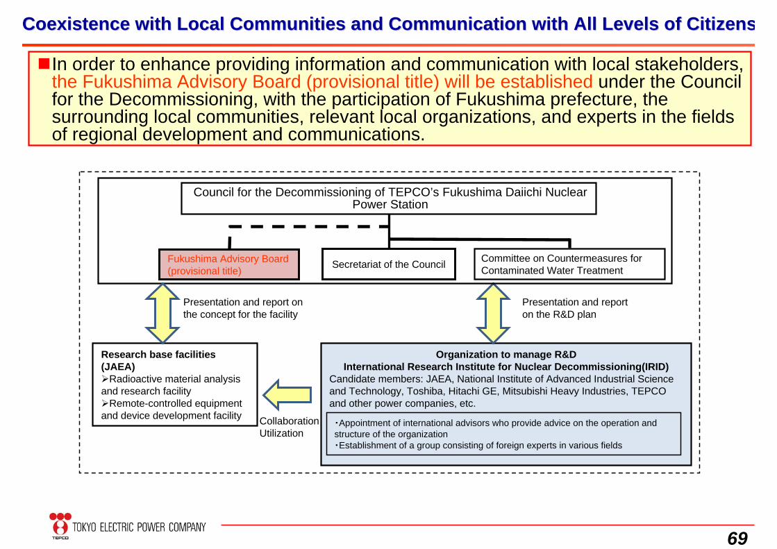
Coexistence with Local Communities and Communication with All LeCoexistence with Local Communities and Communication with All Levels of Citizensvels of Citizens
Council for the Decommissioning of TEPCO’s Fukushima Daiichi Nuclear Power Station
Organization to manage R&DInternational Research Institute for Nuclear Decommissioning(IRID)
Candidate members: JAEA, National Institute of Advanced Industrial Science and Technology, Toshiba, Hitachi GE, Mitsubishi Heavy Industries, TEPCO and other power companies, etc.
Committee on Countermeasures for Contaminated Water Treatment
Research base facilities (JAEA) Radioactive material analysis and research facilityRemote-controlled equipment and device development facility Collaboration
Utilization
Presentation and report on the R&D plan
Presentation and report on the concept for the facility
・Appointment of international advisors who provide advice on the operation and structure of the organization・Establishment of a group consisting of foreign experts in various fields
Secretariat of the CouncilFukushima Advisory Board (provisional title)
In order to enhance providing information and communication with local stakeholders, the Fukushima Advisory Board (provisional title) will be established under the Council for the Decommissioning, with the participation of Fukushima prefecture, the surrounding local communities, relevant local organizations, and experts in the fields of regional development and communications.
70
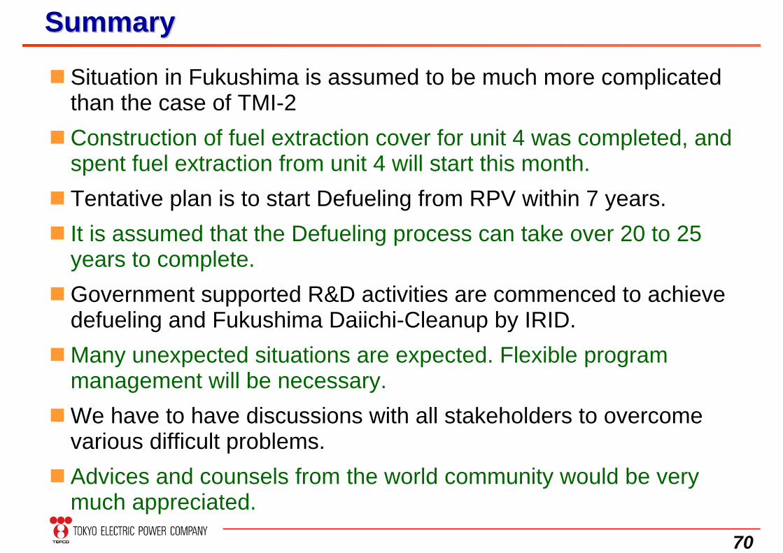
Situation in Fukushima is assumed to be much more complicated than the case of TMI-2
Construction of fuel extraction cover for unit 4 was completed, and spent fuel extraction from unit 4 will start this month.
Tentative plan is to start Defueling from RPV within 7 years. It is assumed that the Defueling process can take over 20 to 25
years to complete.Government supported R&D activities are commenced to achieve
defueling and Fukushima Daiichi-Cleanup by IRID. Many unexpected situations are expected. Flexible program
management will be necessary.We have to have discussions with all stakeholders to overcome
various difficult problems. Advices and counsels from the world community would be very
much appreciated.
SummarySummary
71
Thank you for your attention
Thank you so much for all of your supports extended for us
and
72
Additional Information
73
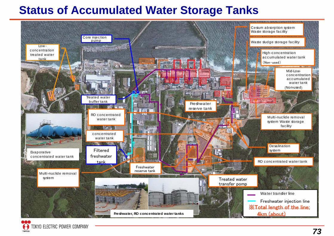
Status of Accumulated Water Storage TanksCesium absorption systemWaste storage facility
Waste sludge storage facility
High-concentration accumulated water tank(Non-used)
Mid-Low-concentration accumulated
water tank(Non-used)
Multi -nuclide removal system Waste storage
facility
Desalination system
RO concentrated water tank
Freshwater reserve tank
RO concentrated water tank
Water transfer line
Freshwater injection line
concentrated water tank
Freshwater reserve tank
Treated water transfer pomp
Multi -nuclide removal system
Filtered freshwater
tank
Treated water buffer tank
Core injection pump
Low-concentration treated water
tank
※Total length of the line; 4km (about)Freshwater, RO concentrated water tanks
Evaporative concentrated water tank
74
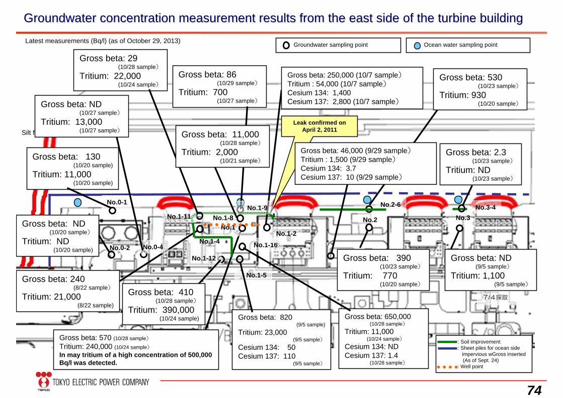
Groundwater concentration measurement results from the east sideGroundwater concentration measurement results from the east side of the turbine buildingof the turbine building
Silt fence
Groundwater sampling point Ocean water sampling point
No.1-4 No.1-16No.1-2
: Soil improvement: Sheet piles for ocean side
impervious wGross inserted(As of Sept. 24)
: Well point
No.2 No.3
Gross beta: 390(10/23 sample)
Tritium: 770(10/20 sample)
7/4採取
Gross beta: ND(9/5 sample)
Tritium: 1,100(9/5 sample)
Gross beta: 250,000 (10/7 sample)Tritium : 54,000 (10/7 sample)Cesium 134: 1,400Cesium 137: 2,800 (10/7 sample)
Gross beta: 570 (10/28 sample)
Tritium: 240,000 (10/24 sample)In may tritium of a high concentration of 500,000 Bq/l was detected.
Gross beta: 650,000(10/28 sample)
Tritium: 11,000(10/24 sample)
Cesium 134: NDCesium 137: 1.4
(10/28 sample)
Latest measurements (Bq/l) (as of October 29, 2013)
Leak confirmed on April 2, 2011
Gross beta: 2.3(10/23 sample)
Tritium: ND(10/23 sample)
No.3-4
Gross beta: 530(10/23 sample)
Tritium: 930(10/20 sample)
No.2-6
No.1
No.1-5
Gross beta: 820(9/5 sample)
Tritium: 23,000(9/5 sample)
Cesium 134: 50Cesium 137: 110
(9/5 sample)
No.0-1
Gross beta: 240(8/22 sample)
Tritium: 21,000(8/22 sample)
Gross beta: 130(10/20 sample)
Tritium: 11,000(10/20 sample)
No.1-8
Gross beta: 86(10/29 sample)
Tritium: 700(10/27 sample)
Gross beta: ND(10/20 sample)
Tritium: ND(10/20 sample) No.0-2
No.1-9No.1-11
Gross beta: 29(10/28 sample)
Tritium: 22,000(10/24 sample)
No.0-4
Gross beta: ND(10/27 sample)
Tritium: 13,000(10/27 sample)
No.1-12
Gross beta: 11,000(10/28 sample)
Tritium: 2,000(10/21 sample)
Gross beta: 410(10/28 sample)
Tritium: 390,000(10/24 sample)
Gross beta: 46,000 (9/29 sample)Tritium : 1,500 (9/29 sample)Cesium 134: 3.7Cesium 137: 10 (9/29 sample)
75
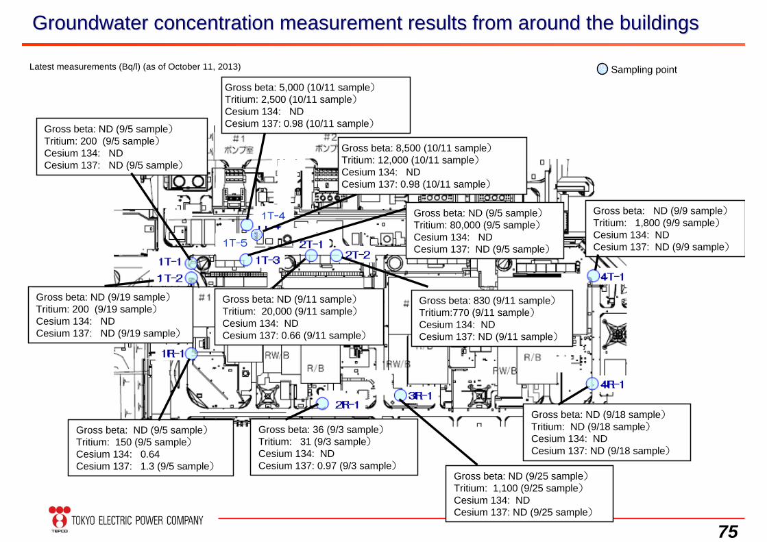
Groundwater concentration measurement results from around the buGroundwater concentration measurement results from around the buildingsildings
Latest measurements (Bq/l) (as of October 11, 2013)
Gross beta: 36 (9/3 sample)Tritium: 31 (9/3 sample)Cesium 134: NDCesium 137: 0.97 (9/3 sample)
Gross beta: ND (9/5 sample)Tritium: 150 (9/5 sample)Cesium 134: 0.64Cesium 137: 1.3 (9/5 sample)
Gross beta: ND (9/5 sample)Tritium: 200 (9/5 sample)Cesium 134: NDCesium 137: ND (9/5 sample)
Sampling point
Gross beta: ND (9/11 sample)Tritium: 20,000 (9/11 sample)Cesium 134: NDCesium 137: 0.66 (9/11 sample)
Gross beta: 830 (9/11 sample)Tritium:770 (9/11 sample)Cesium 134: NDCesium 137: ND (9/11 sample)
Gross beta: ND (9/9 sample)Tritium: 1,800 (9/9 sample)Cesium 134: NDCesium 137: ND (9/9 sample)
Gross beta: ND (9/5 sample)Tritium: 80,000 (9/5 sample)Cesium 134: NDCesium 137: ND (9/5 sample)
Gross beta: 5,000 (10/11 sample)Tritium: 2,500 (10/11 sample)Cesium 134: NDCesium 137: 0.98 (10/11 sample)
Gross beta: ND (9/18 sample)Tritium: ND (9/18 sample)Cesium 134: NDCesium 137: ND (9/18 sample)
Gross beta: ND (9/19 sample)Tritium: 200 (9/19 sample)Cesium 134: NDCesium 137: ND (9/19 sample)
Gross beta: ND (9/25 sample)Tritium: 1,100 (9/25 sample)Cesium 134: NDCesium 137: ND (9/25 sample)
1T-4
1T-5
Gross beta: 8,500 (10/11 sample)Tritium: 12,000 (10/11 sample)Cesium 134: NDCesium 137: 0.98 (10/11 sample)
76
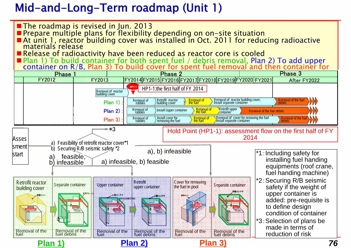
MidMid--andand--LongLong--Term roadmap (Unit 1)Term roadmap (Unit 1)The roadmap is revised in Jun. 2013Prepare multiple plans for flexibility depending on on-site situationAt unit 1, reactor building cover was installed in Oct. 2011 for reducing radioactive radioactive
materials releasematerials releaseRelease of radioactivity have been reduced as reactor core is cooledPlan 1) To build container for both spent fuel / debris removal, Plan 2) To add upper
container on R/B, Plan 3) To build cover for spent fuel removal and then container for debris removal
Plan 2)Plan 1) Plan 3)
a), b) infeasible
Hold Point (HP1-1): assessment flow on the first half of FY 2014Asses
sment start
Phase 1 Phase 3Phase 2FY2012 FY2014FY2013 FY2020FY2019FY2018FY2017FY2016FY2015 After FY2022FY2021
Plan 1) :
Plan 2) :
Plan 3) :
Removal of the fuel debris
Removal of the fuel debris
Removal of the fuel debris
Removal of the fuel
Removal of the fuel
Removal of the fuel
Removal of rubbles
Removal of rubbles
Removal of rubbles Install Upper container
HP1-1:the first half of FY 2014Removal of reactor building cover
Retrofit reactor building cover
Removal of reactor building cover,Install separate container
Removal of cover for removing the fuelInstall separate container
Install cover for removing the fuel
Retrofit upper container
a) Feasibility of retrofit reactor cover*1b) Securing R/B seismic safety *2
*3
*1:Including safety for installing fuel handing equipments (roof crane, fuel handing machine)
*2:Securing R/B seismic safety if the weight of upper container is added: pre-requisite is to define design condition of container
*3:Selection of plans be made in terms of reduction of risk Removal of the
fuelRemoval of the fuel debris Removal of the
fuelRemoval of the fuel debris
Removal of the fuel
Removal of the fuel debris
a) infeasible, b) feasiblea) feasible,b) infeasible
Separate containerUpper containerSeparate container Cover for removing the fuel in pool
Retrofit upper container
Retrofit reactor building cover
77
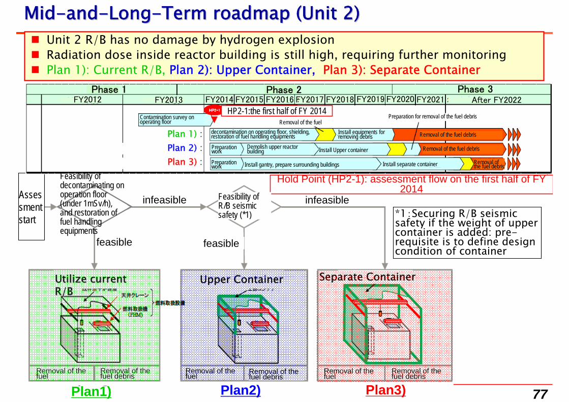
Unit 2 R/B has no damage by hydrogen explosion Radiation dose inside reactor building is still high, requiring further monitoring Plan 1): Current R/B, Plan 2): Upper Container, Plan 3): Separate Container
*1:Securing R/B seismicsafety if the weight of upper container is added: pre-requisite is to define design condition of container
MidMid--andand--LongLong--Term roadmap (Unit 2)Term roadmap (Unit 2)
Removal of the fuel
Removal of the fuel debris
Plan2)Plan1)Removal of the fuel Removal of the
fuel debris Removal of the fuel
Removal of the fuel debris
Plan3)
feasible feasible
infeasibleinfeasible
Separate ContainerUpper Container
Assessment start
Hold Point (HP2-1): assessment flow on the first half of FY 2014
Feasibility of R/B seismic safety (*1)
Phase 1 Phase 3Phase 2FY2012 FY2014FY2013 FY2020FY2019FY2018FY2017FY2016FY2015 After FY2022FY2021
Removal of the fuel debris
Removal of the fuel debris
Removal of the fuel debris
Removal of the fuelPreparation for removal of the fuel debris
Preparation work
Preparation work
Plan 1) :Plan 2) :Plan 3) :
Install Upper container
HP2-1:the first half of FY 2014Contamination survey on operating floor
decontamination on operating floor, shielding, restoration of fuel handling equipments
Install equipments for removing debris
Demolish upper reactor building
Install separate containerInstall gantry, prepare surrounding buildings
Feasibility of decontaminating on operation floor(under 1mSv/h),and restoration of fuel handling equipments
Utilize current Utilize current R/BR/B
78
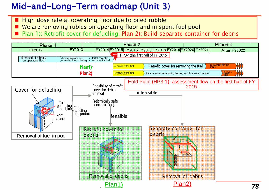
High dose rate at operating floor due to piled rubble We are removing rubles on operating floor and in spent fuel pool Plan 1): Retrofit cover for defueling, Plan 2): Build separate container for debris
Phase 1 Phase 3Phase 2FY2012 FY2014FY2013 FY2020FY2019FY2018FY2017FY2016FY2015 After FY2022FY2021
MidMid--andand--LongLong--Term roadmap (Unit 3)Term roadmap (Unit 3)
Removal of the fuel debris
Removal of the fueldebrisRemoval of the fuel
Removal of the fuel
Plan1)Plan2)
Plan1) Plan2)
Removal of fuel in pool
Removal of debris Removal of debris
feasible
infeasible
Separate container for debris
Cover for defueling
Removal of rubbles on operating floor
HP3-1:the first half of FY 2015
Retrofit cover for debris
Feasibility of retrofit cover for debris removal
(seismically safe construction)
Hold Point (HP3-1): assessment flow on the first half of FY 2015
decontamination on operating floor, shielding,
Install cover for removing the fuel
Retrofit cover for removing the fuelRemove cover for removing the fuel, install separate container
Roof crane
Fuel handlingmachine Fuel
handling equipment
79
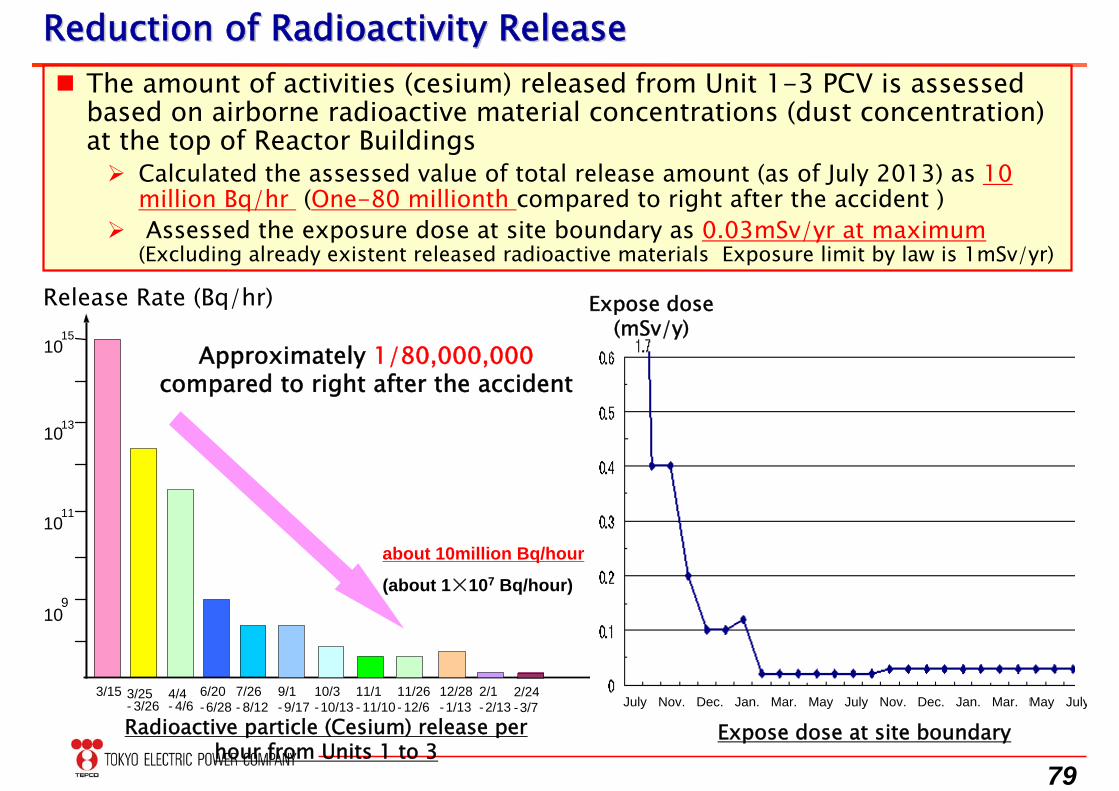
The amount of activities (cesium) released from Unit 1-3 PCV is assessedbased on airborne radioactive material concentrations (dust concentration)at the top of Reactor Buildings Calculated the assessed value of total release amount (as of July 2013) as 10
million Bq/hr (One-80 millionth compared to right after the accident ) Assessed the exposure dose at site boundary as 0.03mSv/yr at maximum
(Excluding already existent released radioactive materials Exposure limit by law is 1mSv/yr)
Reduction of Radioactivity ReleaseReduction of Radioactivity Release
Release Rate (Bq/hr)
Radioactive particle (Cesium) release per hour from Units 1 to 3
1015
1013
1011
109
3/15 3/25- 3/26
6/20-6/28
4/4- 4/6
7/26- 8/12
9/1- 9/17
10/3-10/13
11/1- 11/10
11/26- 12/6
12/28-1/13
2/1-2/13
2/24-3/7
Approximately 1/80,000,000compared to right after the accident
about 10million Bq/hour
(about 1×10⁷ Bq/hour)
Expose dose at site boundary
Expose dose (mSv/y)
May Mar.July Jan.Nov. Dec. MayMar. JulyJan.Nov. Dec.July
80
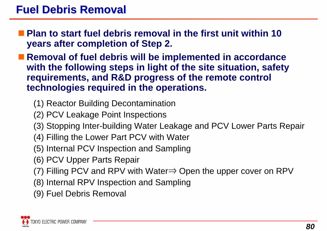
Plan to start fuel debris removal in the first unit within 10 years after completion of Step 2.
Removal of fuel debris will be implemented in accordance with the following steps in light of the site situation, safety requirements, and R&D progress of the remote control technologies required in the operations.
(1) Reactor Building Decontamination(2) PCV Leakage Point Inspections(3) Stopping Inter-building Water Leakage and PCV Lower Parts Repair(4) Filling the Lower Part PCV with Water(5) Internal PCV Inspection and Sampling(6) PCV Upper Parts Repair(7) Filling PCV and RPV with Water⇒ Open the upper cover on RPV(8) Internal RPV Inspection and Sampling(9) Fuel Debris Removal
Fuel Debris RemovalFuel Debris Removal
81
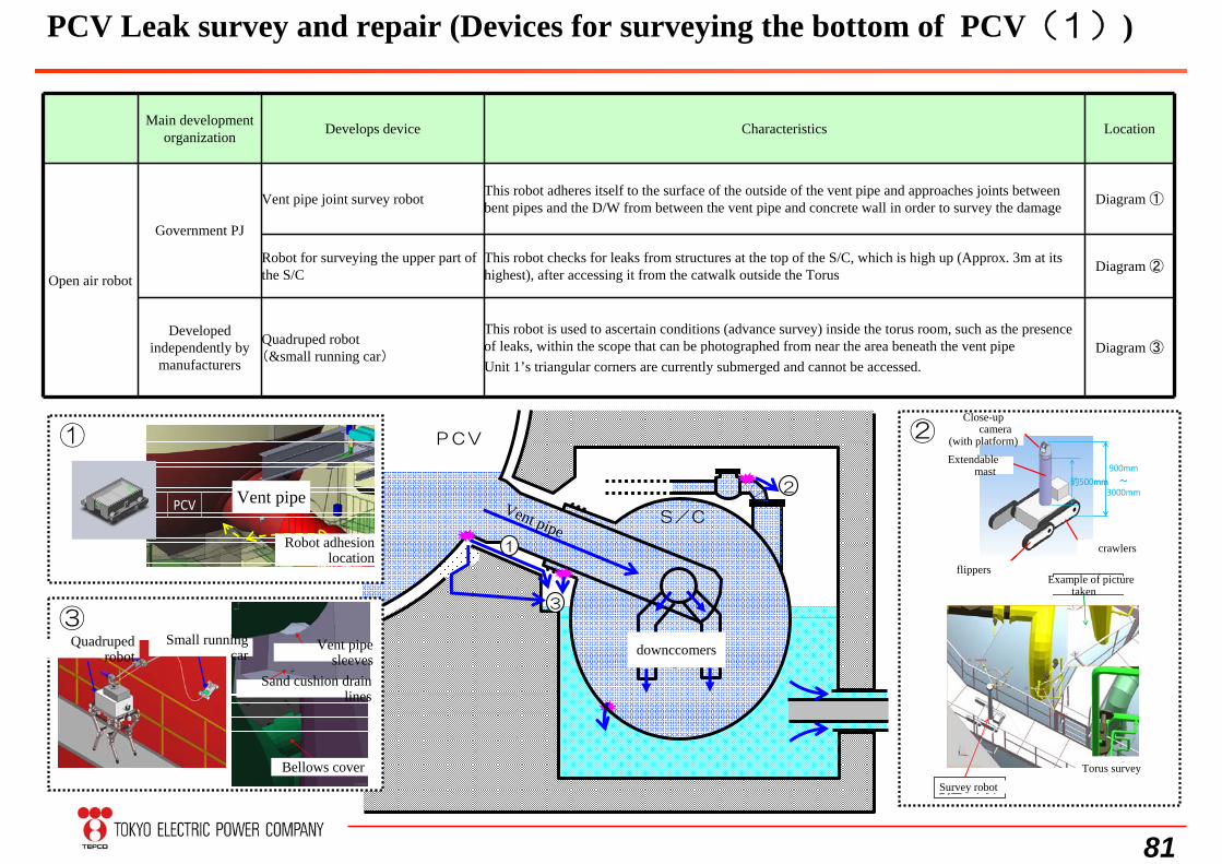
Main development organization Develops device Characteristics Location
Open air robot
Government PJ
Vent pipe joint survey robot This robot adheres itself to the surface of the outside of the vent pipe and approaches joints between bent pipes and the D/W from between the vent pipe and concrete wall in order to survey the damage Diagram ①
Robot for surveying the upper part of the S/C
This robot checks for leaks from structures at the top of the S/C, which is high up (Approx. 3m at its highest), after accessing it from the catwalk outside the Torus Diagram ②
Developed independently by
manufacturers
Quadruped robot(&small running car)
This robot is used to ascertain conditions (advance survey) inside the torus room, such as the presence of leaks, within the scope that can be photographed from near the area beneath the vent pipeUnit 1’s triangular corners are currently submerged and cannot be accessed.
Diagram ③
②
S/CVent pipe
PCV
ダウンカマ
1
2
①
PCV ベント管
ロボット吸着位置
PCV ベント管
ロボット吸着位置
トーラス調査
調査ロボット
撮影画像例
トーラス調査
調査ロボット
撮影画像例
3
③小型走行車4足歩行ロボット
サンドクッションドレンライン
ベント管スリーブ
ベローズカバー
クローラ
フリッパ
伸縮マスト
約500mm
ズームカメラ
(雲台付)
クローラ
フリッパ
伸縮マスト
約500mm
ズームカメラ
(雲台付)
900mm~
3000mm
PCV Leak survey and repair (Devices for surveying the bottom of PCV(1))
Vent pipe
Robot adhesion location
Quadruped robot
Vent pipe sleeves
Sand cushion drain lines
Bellows cover
Small running car downccomers
Close-up camera
(with platform)Extendable
mast
crawlers
flippersExample of picture
taken
Survey robot
Torus survey
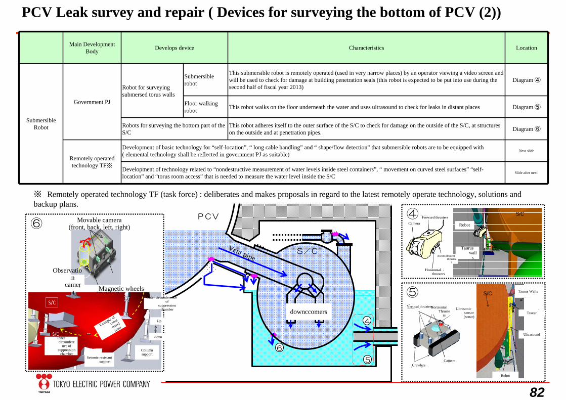
82
Main Development Body Develops device Characteristics Location
Submersible Robot
Government PJ
Robot for surveying submersed torus walls
Submersible robot
This submersible robot is remotely operated (used in very narrow places) by an operator viewing a video screen and will be used to check for damage at building penetration seals (this robot is expected to be put into use during the second half of fiscal year 2013)
Diagram ④
Floor walking robot This robot walks on the floor underneath the water and uses ultrasound to check for leaks in distant places Diagram ⑤
Robots for surveying the bottom part of the S/C
This robot adheres itself to the outer surface of the S/C to check for damage on the outside of the S/C, at structures on the outside and at penetration pipes. Diagram ⑥
Remotely operated technology TF※
Development of basic technology for “self-location”, “ long cable handling” and “ shape/flow detection” that submersible robots are to be equipped with ( elemental technology shall be reflected in government PJ as suitable)
Next slide
Development of technology related to “nondestructive measurement of water levels inside steel containers”, “ movement on curved steel surfaces” “self-location” and “torus room access” that is needed to measure the water level inside the S/C
Slide after next゙
S/CVent pipe
PCV
ダウンカマ
4
6
5
ロボット
トーラス室壁面S/C
超音波
トレーサ
ロボット
トーラス室壁面S/C
超音波
トレーサ
クローラ
垂直スラスタ水平スラスタ
カメラ
超音波センサ(ソナー)
ロボット
トーラス室壁面
S/C昇降スラスタ
前後進スラスタ
カメラ
水平スラスタ
昇降スラスタ
前後進スラスタ
カメラ
水平スラスタ
④
⑤
⑥
ロボット
S/C
ロボット
走行ルート
例
コラムサポート耐震
サポート
天
地
S/C外周側
S/C内周側
S/C
ロボット
走行ルート
例
コラムサポート耐震
サポート
天
地
S/C外周側
S/C内周側
磁石車輪
観察カメラ
移動用カメラ(前後左右)
※ Remotely operated technology TF (task force) : deliberates and makes proposals in regard to the latest remotely operate technology, solutions and backup plans.
PCV Leak survey and repair ( Devices for surveying the bottom of PCV (2))
Movable camera(front, back, left, right)
Observation
camera Magnetic wheels
Inner circumfere
nce of suppression
chamber
Example of
robot
travel
route
Outer circumference of
suppression chamber
Up
down
Column support
Seismic resistant support
downccomers
CameraForward thrusters
Horizontal thrusters
Ascent/descent thruster
s
Robot
Taurus wall
s
Vertical thrusters
CrawlersCamera
Horizontal Thruste
rs
Ultrasonic sensor (sonar)
Taurus Walls
Tracer
Ultrasound
Robot


![Fukushima Dai-Ichi Nuclear Accident Analysis How much do ... · Before Fukushima Dai-ichi Nuclear Accident [Afterthoughts] Less attentions to BDBAs and BDBEs, e.g., devastating tsunami](https://img.pdfslide.net/doc/110x75/5f8ac5453fdf0878a818486a/fukushima-dai-ichi-nuclear-accident-analysis-how-much-do-before-fukushima-dai-ichi.jpg)