Embed Size (px)
Citation preview
- 1 -6159932010-04.P65
CVIC-MODCVIC
CVIC controller- Release 1.6MODCVIC module - Release 1.6
Manual no.: 6159932010
The features and descriptions of our products are subject to changewithout prior notice.

- 3 -
CVIC & MODCVIC - Operator's Manual
6159932010-04.P65
Table of contents
SECTION 1 - WARNINGS.............................................................................................. 51 - Installation ............................................................................................................... 52 - Safety........................................................................................................................ 5
SECTION 2 - INTRODUCTION ...................................................................................... 71 - CVIC Controller ....................................................................................................... 72 - MODCVIC Control Module ...................................................................................... 7
SECTION 3 - DESCRIPTION OF CVIC CONTROLLER AND MODCVIC MODULE .... 91 - CVIC controller ........................................................................................................ 9
1.1 - Mechanical characteristics ................................................................................ 91.2 - Keyboard Layout and Operation ...................................................................... 101.3 - Example: Setting the Date and Time ............................................................... 111.4 - Screen Symbols .............................................................................................. 111.5 - Bottom Front Side............................................................................................ 11
2 - MODCVIC Module .................................................................................................. 122.1 - Technical and Electrical Features .................................................................... 122.2 - Description of the Front Side ........................................................................... 12
SECTION 4 - START-UP.............................................................................................. 131 - Installation Safety Instructions ............................................................................ 132 - Starting up the Controller ..................................................................................... 13
2.1 - Tool Connection ............................................................................................... 132.2 - Emergency Stop .............................................................................................. 132.3 - Switching on .................................................................................................... 132.4 - Language Selection ......................................................................................... 132.5 - Setting the Date and Time ............................................................................... 142.6 - Programming the Tightening Cycles ............................................................... 14
SECTION 5 - PROGRAMMING THE VERSION "L" CONTROLLER ......................... 151 - "CONTROL" Menu................................................................................................. 152 - "PARAMETERS" Menu .......................................................................................... 16
2.1 - "SPINDLE" Menu ............................................................................................. 162.2 - "QUICK CYCLE" Menu .................................................................................... 162.3 - "CYCLE " Menu ............................................................................................... 162.4 - "STATION" Menu ............................................................................................. 162.5 - "PC LINK" Menu .............................................................................................. 17
2.5.1 - Controller ................................................................................................. 172.5.2 – MODCVIC ............................................................................................... 17
- 4 -
CVIC & MODCVIC - Operator's Manual
6159932010-04.P65
SECTION 6 - PROGRAMMING THE VERSION "M" and "H" CONTROLLER .......... 191 - "CONTROL" Menu................................................................................................. 192 - "RESULTS" Menu .................................................................................................. 193 - "PARAMETERS" Menu .......................................................................................... 19
3.1 - "SPINDLE" Menu ............................................................................................. 203.2 - "CYCLES" Menu .............................................................................................. 20
3.2.1 - Introduction .............................................................................................. 203.2.2 - Selecting the Cycle .................................................................................. 203.2.3 - Programming the Phases ........................................................................ 21
3.3 - "QUICK CYCLES" Menu ................................................................................. 263.4 - "LEARNING" Menu .......................................................................................... 273.5 - "STATION" Menu ............................................................................................. 273.6 - Input / Output Configuration ............................................................................ 28
3.6.1 - Overview .................................................................................................. 283.6.2 - Description of Inputs ................................................................................ 293.6.3 - Description of Outputs ............................................................................. 30
3.7 - "PERIPHERALS" Menu ................................................................................... 323.7.1 - Serial Port ................................................................................................ 323.7.2 - RP Output ................................................................................................ 323.7.3 - Bar Code .................................................................................................. 33
SECTION 7 - MAINTENANCE OF THE CVIC CONTROLLER ................................... 341 - "MAINTENANCE" MENU ....................................................................................... 34
1.1 - "TEST" Menu ................................................................................................... 341.2 - "CHANNEL TEST" Menu ................................................................................. 341.3 - "COUNTERS" Menu ........................................................................................ 341.4 - "CALIBRATION" Menu .................................................................................... 35
1.4.1 - "AUTO SPINDLE" Menu .......................................................................... 351.4.2 - "MANU SPINDLE" Menu.......................................................................... 35
1.5 - Changing the Memory Battery ......................................................................... 36
2 - "SERVICE" MENU.................................................................................................. 372.1 - "CONTRAST" Menu ........................................................................................ 372.2 - "DATE" Menu ................................................................................................... 372.3 - "LANGUAGE" Menu ........................................................................................ 372.4 - "ACCESS CODE" Menu .................................................................................. 37
Appendix - PC wiring diagram ................................................................................. 38Appendix - Synchronising several CVIC controllers ............................................. 38Appendix - EC, MC and EC/MC extension wiring diagram ................................... 39Appendix - Tightening Strategies ............................................................................. 47Appendix - Printing Formats for tightening results ................................................ 41Appendix - Cycle flowchart and timing chart .......................................................... 51
1 - Cycle flowchart ................................................................................................... 512 - Cycle timing chart ............................................................................................... 52
- 5 -
CVIC & MODCVIC - Operator's Manual
6159932010-04.P65
SECTION 1 - WARNINGS
1 - INSTALLATION
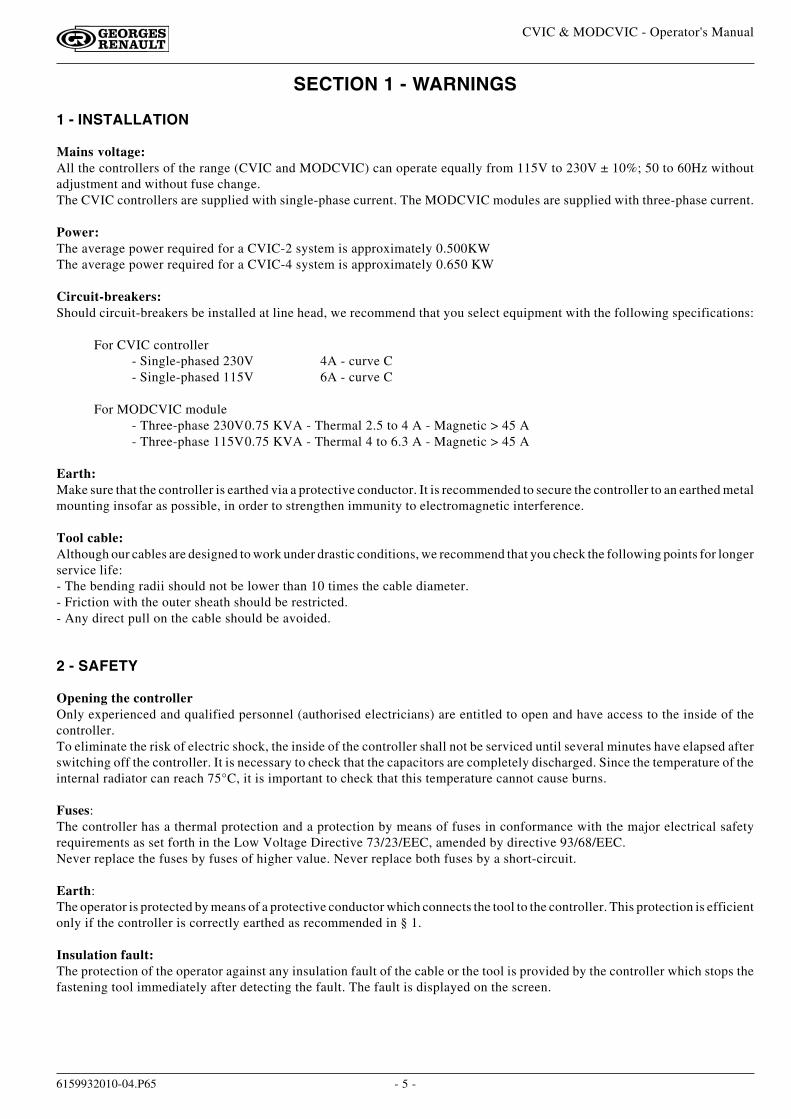
Mains voltage:All the controllers of the range (CVIC and MODCVIC) can operate equally from 115V to 230V ± 10%; 50 to 60Hz withoutadjustment and without fuse change.The CVIC controllers are supplied with single-phase current. The MODCVIC modules are supplied with three-phase current.
Power:The average power required for a CVIC-2 system is approximately 0.500KWThe average power required for a CVIC-4 system is approximately 0.650 KW
Circuit-breakers:Should circuit-breakers be installed at line head, we recommend that you select equipment with the following specifications:
For CVIC controller- Single-phased 230V 4A - curve C- Single-phased 115V 6A - curve C
For MODCVIC module- Three-phase 230V0.75 KVA - Thermal 2.5 to 4 A - Magnetic > 45 A- Three-phase 115V0.75 KVA - Thermal 4 to 6.3 A - Magnetic > 45 A
Earth:Make sure that the controller is earthed via a protective conductor. It is recommended to secure the controller to an earthed metalmounting insofar as possible, in order to strengthen immunity to electromagnetic interference.
Tool cable:Although our cables are designed to work under drastic conditions, we recommend that you check the following points for longerservice life:- The bending radii should not be lower than 10 times the cable diameter.- Friction with the outer sheath should be restricted.- Any direct pull on the cable should be avoided.
2 - SAFETY
Opening the controllerOnly experienced and qualified personnel (authorised electricians) are entitled to open and have access to the inside of thecontroller.To eliminate the risk of electric shock, the inside of the controller shall not be serviced until several minutes have elapsed afterswitching off the controller. It is necessary to check that the capacitors are completely discharged. Since the temperature of theinternal radiator can reach 75°C, it is important to check that this temperature cannot cause burns.
Fuses:The controller has a thermal protection and a protection by means of fuses in conformance with the major electrical safetyrequirements as set forth in the Low Voltage Directive 73/23/EEC, amended by directive 93/68/EEC.Never replace the fuses by fuses of higher value. Never replace both fuses by a short-circuit.
Earth:The operator is protected by means of a protective conductor which connects the tool to the controller. This protection is efficientonly if the controller is correctly earthed as recommended in § 1.
Insulation fault:The protection of the operator against any insulation fault of the cable or the tool is provided by the controller which stops thefastening tool immediately after detecting the fault. The fault is displayed on the screen.

- 6 -
CVIC & MODCVIC - Operator's Manual
6159932010-04.P65
Burning hazard:There is a real burning risk when in contact with the accessible parts of the tool. The selection of the tool and of the controllertakes account of the operating conditions as stated by the user, who shall not exceed the operating limits as specified byGEORGES RENAULT at the time of the selection.
Any excessive internal temperature of the tool electric motor if higher than 100°C is detected by the controller and stops thefastening tool. It can start again only if the temperature decreases to under 80°C.
Tool change:In order to eliminate the risk of electric shock and damage to components, the controller MUST be switched off prior to anytool change. The new tool is automatically recognised as soon as the controller is switched on.
Safety instructions for operating the tools:For your satisfaction and safety, we recommend that you read carefully the safety guides supplied with the tools to be given tothe operators.
- 7 -
CVIC & MODCVIC - Operator's Manual
6159932010-04.P65
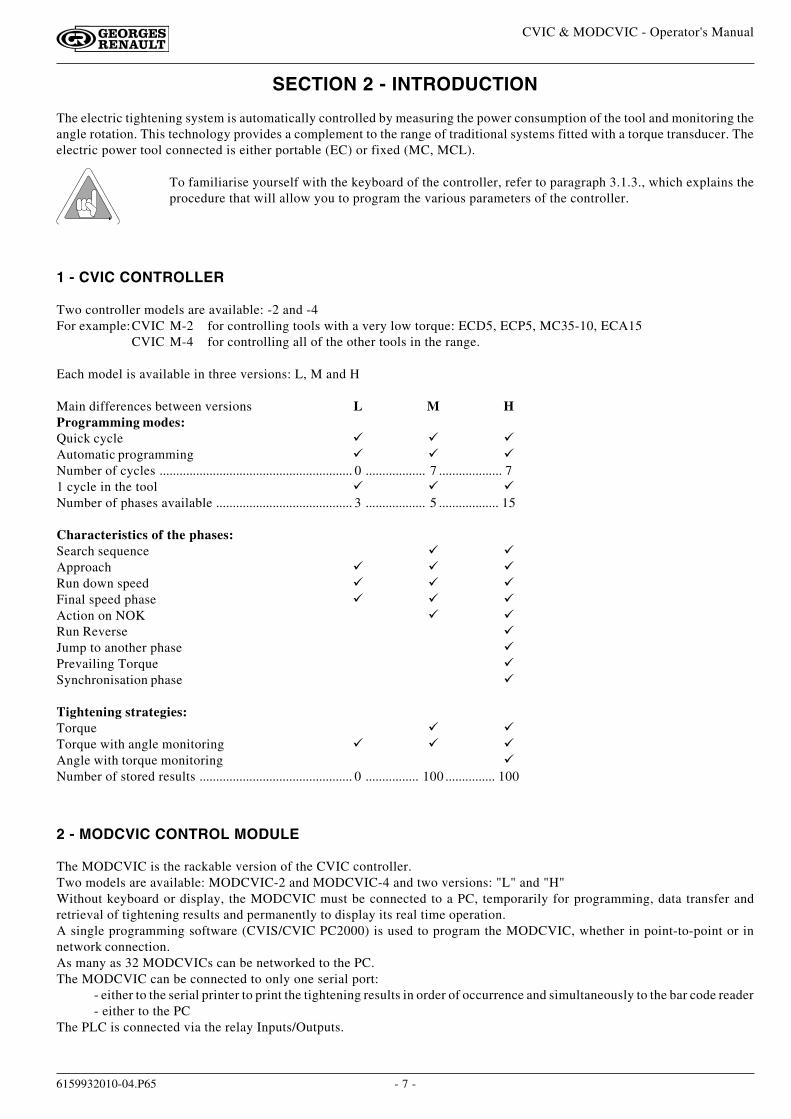
The electric tightening system is automatically controlled by measuring the power consumption of the tool and monitoring theangle rotation. This technology provides a complement to the range of traditional systems fitted with a torque transducer. Theelectric power tool connected is either portable (EC) or fixed (MC, MCL).
To familiarise yourself with the keyboard of the controller, refer to paragraph 3.1.3., which explains theprocedure that will allow you to program the various parameters of the controller.
1 - CVIC CONTROLLER
Two controller models are available: -2 and -4For example:CVIC M-2 for controlling tools with a very low torque: ECD5, ECP5, MC35-10, ECA15
CVIC M-4 for controlling all of the other tools in the range.
Each model is available in three versions: L, M and H
Main differences between versions L M HProgramming modes:Quick cycle � � �Automatic programming � � �Number of cycles .......................................................... 0 .................. 7 ................... 71 cycle in the tool � � �Number of phases available ......................................... 3 .................. 5 .................. 15
Characteristics of the phases:Search sequence � �Approach � � �Run down speed � � �Final speed phase � � �Action on NOK � �Run Reverse �Jump to another phase �Prevailing Torque �Synchronisation phase �
Tightening strategies:Torque � �Torque with angle monitoring � � �Angle with torque monitoring �Number of stored results .............................................. 0 ................ 100 ............... 100
SECTION 2 - INTRODUCTION
2 - MODCVIC CONTROL MODULE
The MODCVIC is the rackable version of the CVIC controller.Two models are available: MODCVIC-2 and MODCVIC-4 and two versions: "L" and "H"Without keyboard or display, the MODCVIC must be connected to a PC, temporarily for programming, data transfer andretrieval of tightening results and permanently to display its real time operation.A single programming software (CVIS/CVIC PC2000) is used to program the MODCVIC, whether in point-to-point or innetwork connection.As many as 32 MODCVICs can be networked to the PC.The MODCVIC can be connected to only one serial port:
- either to the serial printer to print the tightening results in order of occurrence and simultaneously to the bar code reader- either to the PC
The PLC is connected via the relay Inputs/Outputs.

- 8 -
CVIC & MODCVIC - Operator's Manual
6159932010-04.P65
- 9 -
CVIC & MODCVIC - Operator's Manual
6159932010-04.P65
SECTION 3 - DESCRIPTION OF CVIC CONTROLLER AND MODCVIC MODULE
1 - CVIC controller
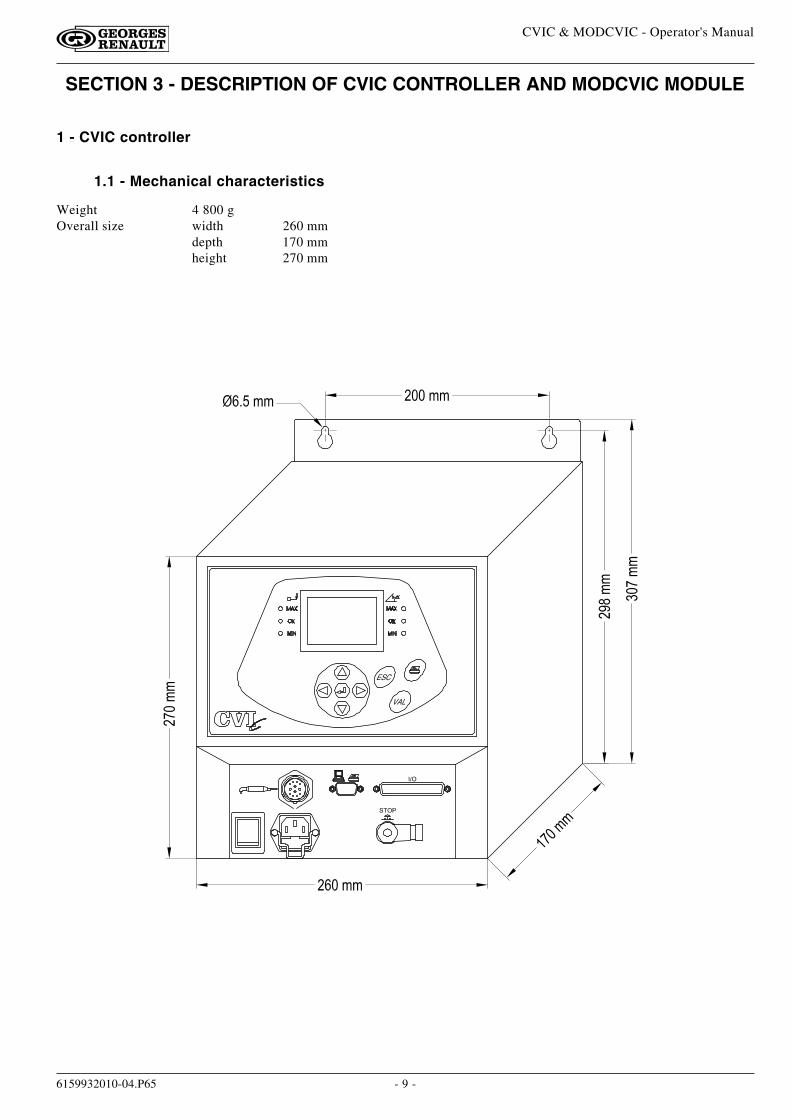
1.1 - Mechanical characteristics
Weight 4 800 gOverall size width 260 mm
depth 170 mmheight 270 mm
- 10 -
CVIC & MODCVIC - Operator's Manual
6159932010-04.P65
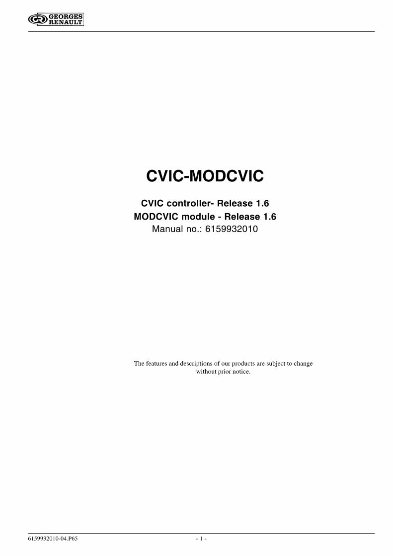
1.2 - Keyboard Layout and Operation
� � �
� � �
�
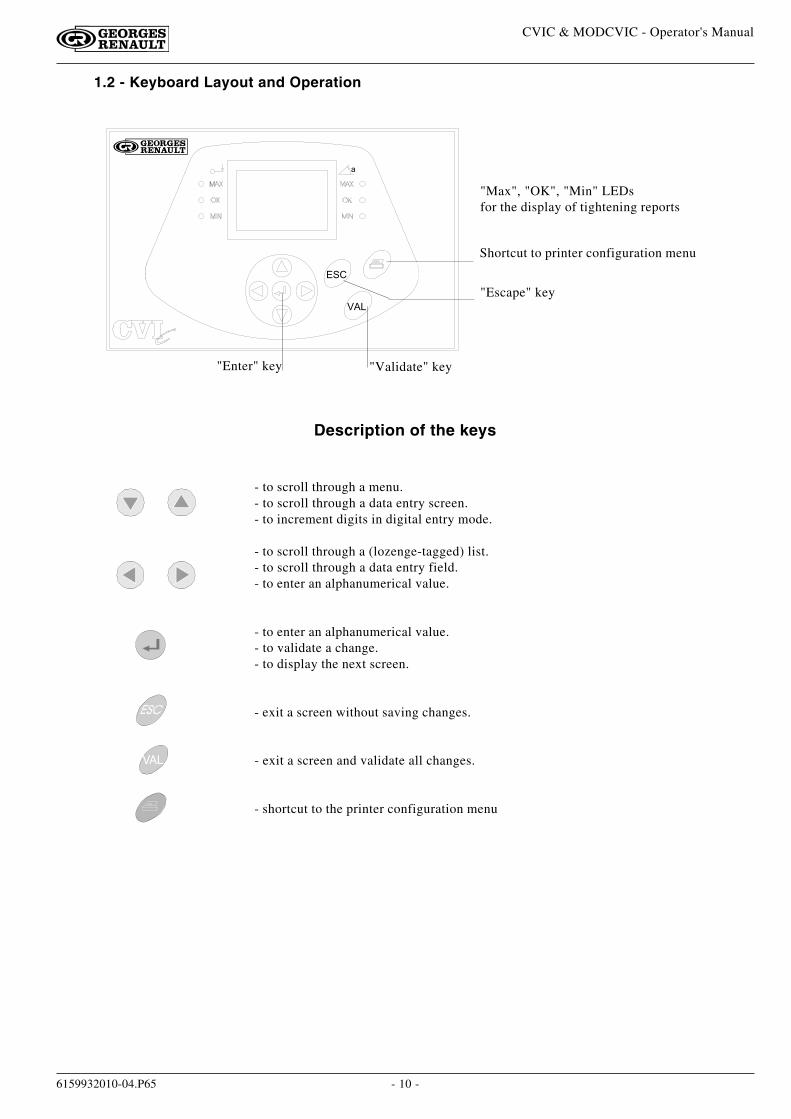
"Validate" key
"Max", "OK", "Min" LEDsfor the display of tightening reports
Shortcut to printer configuration menu
"Escape" key
"Enter" key
VAL
- to scroll through a menu.- to scroll through a data entry screen.- to increment digits in digital entry mode.
- to scroll through a (lozenge-tagged) list.- to scroll through a data entry field.- to enter an alphanumerical value.
- to enter an alphanumerical value.- to validate a change.- to display the next screen.
- exit a screen without saving changes.
- exit a screen and validate all changes.
- shortcut to the printer configuration menu
Description of the keys
- 11 -
CVIC & MODCVIC - Operator's Manual
6159932010-04.P65
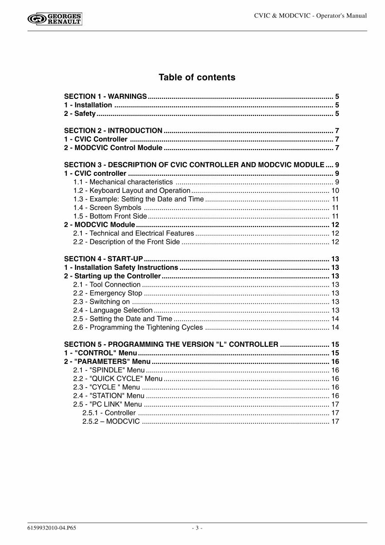
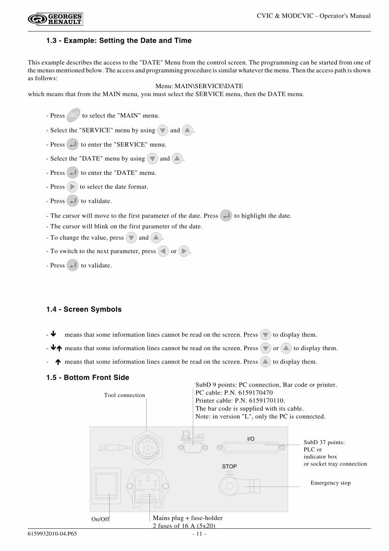
SubD 9 points: PC connection, Bar code or printer.PC cable: P.N. 6159170470Printer cable: P.N. 6159170110.The bar code is supplied with its cable.Note: in version "L", only the PC is connected.
� �
� � SubD 37 points:PLC orindicator boxor socket tray connection
Emergency stop
On/Off Mains plug + fuse-holder2 fuses of 16 A (5x20)
Tool connection
1.5 - Bottom Front Side
1.4 - Screen Symbols
- � means that some information lines cannot be read on the screen. Press to display them.
- �� means that some information lines cannot be read on the screen. Press or to display them.
-�� means that some information lines cannot be read on the screen. Press to display them.
1.3 - Example: Setting the Date and Time
This example describes the access to the "DATE" Menu from the control screen. The programming can be started from one ofthe menus mentioned below. The access and programming procedure is similar whatever the menu. Then the access path is shownas follows:
Menu: MAIN\SERVICE\DATEwhich means that from the MAIN menu, you must select the SERVICE menu, then the DATE menu.
- Press to select the "MAIN" menu.
- Select the "SERVICE" menu by using and .
- Press to enter the "SERVICE" menu.
- Select the "DATE" menu by using and .
- Press to enter the "DATE" menu.
- Press to select the date format.
- Press to validate.
- The cursor will move to the first parameter of the date. Press to highlight the date.
- The cursor will blink on the first parameter of the date.
- To change the value, press and .
- To switch to the next parameter, press or .
- Press to validate.
- 12 -
CVIC & MODCVIC - Operator's Manual
6159932010-04.P65
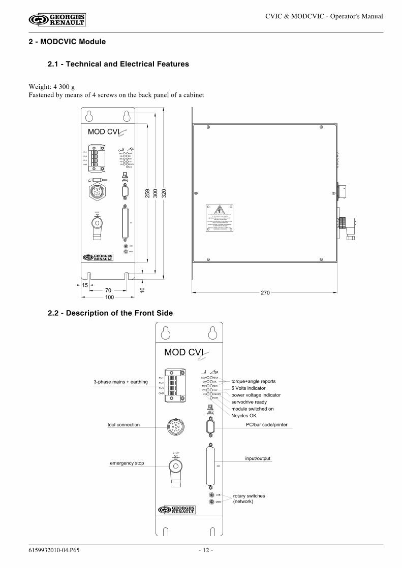
2.2 - Description of the Front Side
2 - MODCVIC Module
2.1 - Technical and Electrical Features
Weight: 4 300 gFastened by means of 4 screws on the back panel of a cabinet
� � �
���
���
���
� � �
� �� �
��
� � � �
� � � � � � � � � � � � � � � � � � � �
� � � � � � � � � � � � � � � � � � �
� � � � � � � � � � � � � � � � � � � � � � � � � � � � � � � �
� � � � � � � � � � � � � � � � � � � �
� � � � � � � � � � � � � � � � � � � � � � � � � � � � �
� � � � � � � � � � � � � � � � � � � � � � � � � � � � � �
� � � � � � � � � � � � � � � �
� � � � � � � � � � � � � � � � � � � � � � � � � � � � � � � � � �
� � � � � � � � � � � � � � � � � � � � � � � � � � � � � �
� � � � � � � � � � � � � � � � � � �
� � �
� � �
!�
� �
"
�
#��
�
�
� �
��
!�
"
#��
� ��
�
� � �
� �
� $
� � %
& �
� � �
� � �
� ' ( �
� �
� ' ( �
� ' ( �
�
& �
� � %
� � � � �
� � �
)
� * + ' ) , - � . ) / 0 , � & � - ) 1 2 ' / 0 3
2 4 4 5 � 6 4 0 0 - 6 2 / 4 0
1 4 2 ) 1 7 � , 8 / 2 6 ' - ,9 0 - 2 8 4 1 : ;
- . - 1 3 - 0 6 7 � , 2 4 +/ 0 + < 2 $ 4 < 2 + < 2
� � $ = ) 1 � 6 4 > - $ + 1 / 0 2 - 1
2 4 1 ? < - & ) 0 3 5 - � 1 - + 4 1 2 ,
+ 4 8 - 1 � @ 4 5 2 ) 3 - � / 0 > / 6 ) 2 4 1
� � 4 5 2 , � / 0 > / 6 ) 2 4 1
, - 1 @ 4 > 1 / @ - � 1 - ) > 7
. 4 > < 5 - � , 8 / 2 6 ' - > � 4 0
� 6 7 6 5 - , �
� � � �
� � �
� � �
!�
� �
"
�
#��
�
�
� �
��
!�
"
#��
� ��
�
� � �
� �
� $
� � %
& �
� � �
� � �
� ' ( �
� �
� ' ( �
� ' ( �
�
& �
� � %
� � � � �
� � �
)

- 13 -
CVIC & MODCVIC - Operator's Manual
6159932010-04.P65
SECTION 4 - START-UP
1 - Installation Safety Instructions
Before switching on, make sure that the controller is installed in accordance with the installation andsafety instructions mentioned in this manual, Section 1: "Warnings".
2 - Starting up the Controller
On receiving the controller, check that the following elements are included in the support kit:- the SubD 37 point connector- the mains cable- 2 fuses of 16A
2.1 - Tool Connection
Make sure that the controller is switched off and connect the tool to the front side of the controller.
2.2 - Emergency Stop
Check that the "EMERGENCY STOP" (STOP) plug is correctly connectedto the front side of the controller. The emergency stop can be connected eitherto the PLC, or to a push-button close to the tightening station. If not connected,check that the strap is correctly positioned inside the plug (see diagramopposite). The opening of the " STOP "contact disables the power circuit.
2.3 - Switching on
Trip the switch on the front side of the controller to switch on the controller.
When switched on, the controller automatically detects the correct operation of the tool and of the controller itself.If everything is OK, the control screen is displayed by the CVIC.
If a problem occurs when the controller is switched on, the screen displays the message: "not ready".
Press to display a second screen which provides more details about the cause of the problem.
2.4 - Language Selection
- Menu : MAIN\SERVICE\LANGUAGE
- The default language used by the controller is the French language. Use and to select your language.
The available languages are: French, English, Spanish, German, Italian and Dutch.
- Validate your selection and press as many times as necessary to go back to the control screen.
See Keyboard Layout and Operation (page 10) and Programming Example (page11) if necessary.
+ 5 < 34 < 2 5 - 2 � ) � )
�
�
$
�
$ �
- 14 -
CVIC & MODCVIC - Operator's Manual
6159932010-04.P65
2.5 - Setting the Date and Time
- Menu: MAIN\SERVICE\DATE.- Allows you to select the format: (DD/MM/YY, MM/DD/YY, YY/MM/DD).- Setting the date.- Setting the time.
2.6 - Programming the Tightening Cycles
Presentation of the various tightening cycles.
The controller allows you to have access to various programming levels depending on your knowledge in the field offastening:
- LearningAfter entering the tightening torque, a guided sequence of tightenings allows the controller to learn thecharacteristics of the joint to be achieved.
- Quick cyclesAfter entering and validating the tightening torque and a maximum tightening angle (optional), the otherparameters are automatically set by the controller to default values which comply with most applications.
- CyclesIn this mode, you can program all the parameters manually (speed, acceleration, run down speed torque, torquetolerances). You can change all the parameters automatically set in the previous 2 programming modes.
For further details, refer to section "Programming the Cycles".
Section 5 - Programming the Version "L" Controller.Section 6 - Programming the Version "M" and "H" Controller.
- 15 -
CVIC & MODCVIC - Operator's Manual
6159932010-04.P65
SECTION 5 - PROGRAMMING THE VERSION "L" CONTROLLER
1 - "CONTROL" MENU
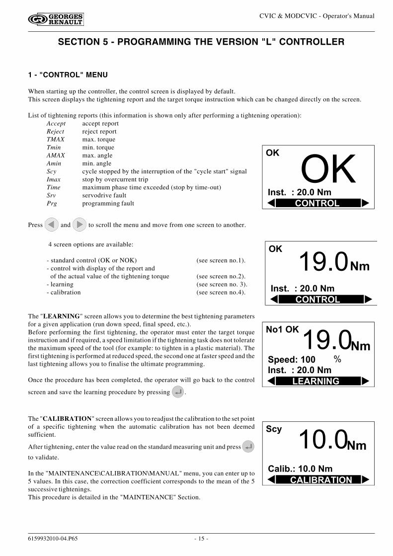
When starting up the controller, the control screen is displayed by default.This screen displays the tightening report and the target torque instruction which can be changed directly on the screen.
List of tightening reports (this information is shown only after performing a tightening operation):Accept accept reportReject reject reportTMAX max. torqueTmin min. torqueAMAX max. angleAmin min. angleScy cycle stopped by the interruption of the "cycle start" signalImax stop by overcurrent tripTime maximum phase time exceeded (stop by time-out)Srv servodrive faultPrg programming fault
Press and to scroll the menu and move from one screen to another.
4 screen options are available:
- standard control (OK or NOK) (see screen no.1).- control with display of the report and
of the actual value of the tightening torque (see screen no.2).- learning (see screen no. 3).- calibration (see screen no.4).
The "LEARNING" screen allows you to determine the best tightening parametersfor a given application (run down speed, final speed, etc.).Before performing the first tightening, the operator must enter the target torqueinstruction and if required, a speed limitation if the tightening task does not toleratethe maximum speed of the tool (for example: to tighten in a plastic material). Thefirst tightening is performed at reduced speed, the second one at faster speed and thelast tightening allows you to finalise the ultimate programming.
Once the procedure has been completed, the operator will go back to the control
screen and save the learning procedure by pressing .
The "CALIBRATION" screen allows you to readjust the calibration to the set pointof a specific tightening when the automatic calibration has not been deemedsufficient.
After tightening, enter the value read on the standard measuring unit and press
to validate.
In the "MAINTENANCE\CALIBRATION\MANUAL" menu, you can enter up to5 values. In this case, the correction coefficient corresponds to the mean of the 5successive tightenings.This procedure is detailed in the "MAINTENANCE" Section.
"� �
� � � � � � � � � � � � �
� � � � � � �
� � �
� � � � � � � � � � � � �
� � � � � � � � � � �
� � ) � �
� � � � � �
� � � � � � � � � � � � �
� � � � � � � �
� � ! � � � � A
� � ) � �
� � ) �� �
� � � � � � � � � � � � �
� � � � � � �
�
- 16 -
CVIC & MODCVIC - Operator's Manual
6159932010-04.P65
2 - "PARAMETERS" MENU
The "PARAMETERS" menu allows you to:- display the tool features "SPINDLE" menu- correct the parameters of the cycle "CYCLES" menu"- dedicate the application "STATION" menu- program the PC connection "PC LINK" menu
2.1 - "SPINDLE" Menu
Menu: MAIN\PARAMETERS\SPINDLEThis menu displays the features of the controller and the features read in the tool memory.The data cannot be changed.
2.2 - "QUICK CYCLE" Menu
Menu: MAIN\PARAMETERS\QUICK CYCLEIt is accessible when no cycle has been saved in the tool memory. This menu allows you to program a cycle without runningthe LEARNING sequence. By default, the quick cycle contains a run down speed phase and a final speed phase. Theoperator only programs the target torque and the maximum angle on the screen.
To do so, select a cycle and press .
For the programming procedure, refer to paragraph 3.1.3.
It is the controller itself which calculates the speeds and all of the other default parameters (minimum speed, maximumspeed, etc.).According to the versions (L - M - H), it is possible to insert and program 1 or several other phases manually.
In the version L CVIC, the tightening cycle is stored in the tool memory and corresponds to cycle "0" (zero). It can include3 phases: approach, run down speed and final speed phase. Only the run down speed and final speed phases are optimisedautomatically with the "Learning" and "Quick cycle" programming modes. The approach phase must be inserted andprogrammed manually. See next pages for the description of the cycle and phases.
2.3 - "CYCLE " Menu
Menu: MAIN\PARAMETERS\CYCLEIt is accessible when a quick cycle has been saved in the tool memory, using one of the LEARNING or QUICK CYCLESprogramming methods.It allows you to change the parameters of the Run down speed and Final speed phases obtained in the 2 programmingmodes.It allows you to insert an approach phase.See next pages for the description of the cycle and phases.
2.4 - "STATION" Menu
Menu: MAIN\PARAMETERS\STATIONThe "STATION" menu allows you to configure the following parameters:Unit Nm/Ft.Lb/In.Lb/Kg.m/Kg.cmDir direction: right/leftRv speed this speed is used at each run reverse command by the operator (the run reverse speeds used during the
cycle can be programmed in each phase or in each cycle according to the case. (See hereafter in thismanual).
Acknow error acknowledgement: yes/no (to validate start cycle after a reject report).Scy pulse start cycle by pulses: the "start cycle" signal is activated by a pulse.RP duration A value which is different from 0 allows you to program the pulse (0.1 to 4.0 s) reports (accept, reject)
at end of cycle.With a value equal to 0, you can have a constant "0" or "1" status of report.
- 17 -
CVIC & MODCVIC - Operator's Manual
6159932010-04.P65
2.5 - "PC LINK" Menu
Menu: MAIN\PARAMETERS\PC LINK
2.5.1 - Controller
The parameters used for the data transfer to PC are as follows:RS232/RS422:
RS232 default standard type used for connecting a PC and a single controllerRS422 used in a network configuration only
Baud rate from 300 to 19,200 Bauds, 7 or 8 data bits, 1 or 2 stop bits, no parity/even/oddDefault values: 19,200 Bauds, 8 data bits, 1 stop bit, no parity.
Slave no. : 0-254. In a network configuration, the PC is connected to several controllers at the sametime. The "Intermediate" or "end of line" differentiation is obtained by resistance wiring inthe connectors of the network cable. (See wiring diagrams).For further information about the network connection, refer to the "CVIPC" Operator's
Manual.
2.5.2 – MODCVIC
For the MODCVIC module, the switching of the communications standard RS232 / RS422 is automatic dependingon the address selected by the rotary switches:
- address 0 implies standard RS232 for the connection of a PC and a single controller- any other address selected implies standard RS422 for a network connection.
The other parameters are set to:- 19,200 bauds- 8 data bits- 1 stop bit- no parity
They cannot be programmed by the PC.In the case of a network connection, the "Intermediate" or "end of line" differentiation is obtained by resistancewiring in the connectors of the network cable. (See wiring diagrams).

- 18 -
CVIC & MODCVIC - Operator's Manual
6159932010-04.P65
- 19 -
CVIC & MODCVIC - Operator's Manual
6159932010-04.P65
� � � �� � � � � � � � � � � � � � � � � � �
� � � �� � �
�" #
SECTION 6 - PROGRAMMING THE VERSION "M" and "H" CONTROLLER
This section explains how you can change the default settings in the main menus of the controller.
1 - "CONTROL" MENU
� � � �
� �
�" #
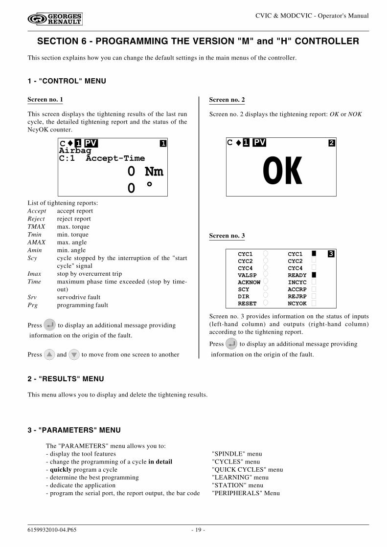
This screen displays the tightening results of the last runcycle, the detailed tightening report and the status of theNcyOK counter.
Screen no. 2 displays the tightening report: OK or NOK
Screen no. 3 provides information on the status of inputs(left-hand column) and outputs (right-hand column)according to the tightening report.
Press to display an additional message providing
information on the origin of the fault.
2 - "RESULTS" MENU
This menu allows you to display and delete the tightening results.
Screen no. 1 Screen no. 2
Screen no. 3
3 - "PARAMETERS" MENU
The "PARAMETERS" menu allows you to:- display the tool features "SPINDLE" menu- change the programming of a cycle in detail "CYCLES" menu- quickly program a cycle "QUICK CYCLES" menu- determine the best programming "LEARNING" menu- dedicate the application "STATION" menu- program the serial port, the report output, the bar code "PERIPHERALS" Menu
List of tightening reports:Accept accept reportReject reject reportTMAX max. torqueTmin min. torqueAMAX max. angleAmin min. angleScy cycle stopped by the interruption of the "start
cycle" signalImax stop by overcurrent tripTime maximum phase time exceeded (stop by time-
out)Srv servodrive faultPrg programming fault
Press to display an additional message providing
information on the origin of the fault.
Press and to move from one screen to another
� � � �� � � �� � � �� � � � �� � � � � �� � �� !! " � " �
� � � �� � � �� � � �! " � � � � � � �� � � ! �! " # ! �� � � � �
$
- 20 -
CVIC & MODCVIC - Operator's Manual
6159932010-04.P65
3.1 - "SPINDLE" Menu
This menu displays the features of the controller and the features read in the tool memory.The data cannot be changed.
3.2 - "CYCLES" Menu
3.2.1 - Introduction
This menu allows you to change or create the programming of the cycles.A tightening cycle consists of a sequence of phases run consecutively. Each phase is defined by main parametersand tightening instructions according to the selected type of tightening and motor settings.
Number of phases available CVIC version M... 5CVIC version H... 15
The various phases available in a cycle are:Search sequence SApproach pRun down speed DFinal speed FAction on NOK VEmpty phase
The additional phases for version H are:Run reverse RPrevailing torque PJump JSynchro waiting W
The procedure for programming the cycle can be broken down as follows:- Selecting the cycle- Selecting and sequencing the phases- Programming the parameters of each phase- Selecting an Action on NOK or not- Entering a comment- Programming the Number of cycles OK
Important: the "0" cycle is a special cycle as it is integrated in the tool memory.It can include 3 phases: "Approach", "Run down speed" and "Final speed phase".When connecting the tool, the "0" cycle is selected by the controller if no other cycle input is positioned at 1.In this way, the tool can be connected and can run its cycle on any controller without new programming.
3.2.2 - Selecting the Cycle
Menu: MAIN\PARAMETERS\CYCLES
The list of the cycles already programmed is displayed. Select a number and press to validate.
- 21 -
CVIC & MODCVIC - Operator's Manual
6159932010-04.P65
3.2.3 - Programming the Phases
After selecting a cycle, the cursor will move to the line where the various phases of the selected cycle are shown.You will be allowed to modify, insert or delete a phase.
Creating (or changing) a phase:
Using and select the phase that you want to change.
To change a phase, press to select "Chg". Press to validate.
The phase type is highlighted. Use and to select the phase type. Press to validate.
Inserting a phase
To insert a phase in a cycle already programmed, you must proceed as follows:
1 - Create a blank before the phase before which you want to insert a new phase.
For this purpose, position the cursor on the phase before which you want to insert a new phase.
Select "Ins" by pressing then .
Press to validate.
2 - Proceed as before to create a phase.
To change a phase, press to select "Chg". Press to validate.
The phase type is highlighted. Use and to select the phase type. Press to validate.
Deleting a phase
Position the cursor on the phase that you want to delete.
Select "Del" by pressing then . Press to validate.
- 22 -
CVIC & MODCVIC - Operator's Manual
6159932010-04.P65
Programming the parameters
Using and , position the cursor on the phase of which you want to program the parameters.
Press to validate.
Search Sequence Phase (M - H)
The maximum time is simply displayed for the Search sequence phase as it is implicitely equal to the number ofrotations multiplied by the rotation time + stop time.Intertime time programmed between this phase and the next one: 0 - 20 sN. rotat. number of rotations: 1 - 9Stop time stop time: 0 - 20 sRot. type rotation type: time/angleRot. time rotation time: 0 - 50 sorRot. angle rotation angle: 0 - 999°Dir direction: right/left/alternate. If the direction is alternate, half the rotations are clockwise
and the other half are in the opposite direction.Speed rotational speed: 0 - 100 %Acceler acceleration rate: 0 - 20 s
No phase RP
Approach Phase (L - M - H)
It allows you to quickly approach the fastener without reaching the joint. It is particularly recommended in the caseof hard joints for which the approach speed should be restricted in order to control the final torque.Intertime time programmed between this phase and the next one: 0 - 20 sN. rotat. number of rotations performed by the tool during this phase : 0 - 100T. max maximum torque which should not be exceeded during this phase:
0 Nm to max. value of the spindle.Other...
Press .
Thread type right/leftSpeed rotational speed 0-100 %Acceler 0-20 sReset The Reset function allows you to reset the torque and/or angle values at the beginning of
the current phase.
The phase RP is OK if:
- the torque is lower than the programmed maximum torqueand- if the programmed number of rotations has been reached
- 23 -
CVIC & MODCVIC - Operator's Manual
6159932010-04.P65
Final speed Phase (L - M - H)
Max time phase running time. 0.01 - 99 sIntertime time programmed between this phase and the next one: 0 - 20 sTightening strategy torque/torque+angleAdditional strategy for version H: angle+torqueTmin minimum torque: 0 Nm to max. value of the spindleTtarget target torque: 0 Nm to max. value of the spindleTmax maximum torque: 0 Nm to max. value of the spindleThreshold angle threshold: 0 Nm to max. value of the spindle.Amin minimum angle: 0 - 999°Amax maximum angle: 0 - 999°Asafe safety angle: 0 - 999°Other...
Press
Motor settingsThread right/leftSpeed rotational speed: 0 - 100 %Acceler acceleration rate: 0 - 20 sReset The Reset function allows you to reset the torque and/or angle values at the beginning of
the current phase.External stop The following conditions must be met for the system to stop the current phase and shift to
the next one:- the "external stop" parameter must be on "yes" in this screen- the signal at the "external stop" input of the Input/Output connector must shift to "1".
Detailed RP. See tightening strategies (torque, torque + angle, angle + torque and prevailing torque) in Appendix 1.
Run down speed Phase (L - M - H)
Max time phase running time. 0.01 - 99 sIntertime time programmed between this phase and the next one: 0 - 20 sTtarget target torque: 0 Nm to max. value of the spindle (screw approach torque)Other...
Press .
Motor settings:Thread right/leftSpeed rotational speed: 0 - 100 %Acceler acceleration rate: 0 - 20 sReset The Reset function allows you to reset the torque and/or angle values at the beginning of
the current phase.External stop The following conditions must be met for the system to stop the current phase and shift to
the next one:- the "external stop" parameter must be on "yes" in this screen- the signal at the "external stop" input of the Input/Output connector must shift to "1".
No phase RP
- 24 -
CVIC & MODCVIC - Operator's Manual
6159932010-04.P65
Action on NOK Phase (M-H)
When there is a reject report (max. torque or max. angle reached, etc...), it is possible to apply a specific correctiveaction to the cycle, either by stopping the cycle or by programming a corrective phase.For example: untighten the screw, repeat tightening, etc.You must choose first: - the fault(s) to which you want to apply a corrective action.
- the number of tests (from 1 to 99)Various actions on NOK are available:End the tightening cycle is stoppedRv+End a Run Reverse phase is run according to the programmed time then the cycle is stoppedJump the cycle proceeds to the indicated phaseRv+Jump a run reverse phase is run according to the programmed time, then the cycle proceeds to the
indicated phase.Rv time Run reverse time: 0 - 99 s
No phase RP
Run Reverse Phase (H)
Max time Phase running timeout: 0.01 - 99 sIntertime time programmed between this phase and the next one: 0 - 20 sStrategy torque/torque+angle/angle+torqueTmin minimum torque: 0 Nm to max. value of the spindleTmax maximum torque: 0 Nm to max. value of the spindleTsafe safety torque: 0 Nm to max. value of the spindleThreshold angle threshold: 0 Nm to max. value of the spindle.Amin minimum angle: 0 - 999°A.target target angle: 0 - 999°Amax maximum angle: 0 - 999°Other...
Press
Motor settingsThread right/leftSpeed rotational speed: 0 - 100 %Acceler acceleration rate: 0 - 20 sReset The Reset function allows you to reset the torque and/or angle values at the beginning of the
current phase.External stop The following conditions must be met for the system to stop the current phase and shift to the
next one:- the "external stop" parameter must be on "yes" in this screen- the signal at the "external stop" input of the Input/Output connector must shift to "1".
Detailed RP. See tightening strategies (torque, torque + angle, angle + torque and prevailing torque) inAppendix 1.
Jump phase (H)
This phase allows you to design more sophisticated cycles.
For example: D F1 V1 F2 --- F3 J1
D run down speedF1 final speed phaseV1 action on NOK: - if NOK, jump to phase 6 (F3)
- otherwise, phase F2 is run then the cycle is stopped--- empty phase: the cycle is stoppedF3 corrective phase in case of NOK on phase 2J1 jump to phase 4 (F2) to finish
No phase RP
- 25 -
CVIC & MODCVIC - Operator's Manual
6159932010-04.P65
Prevailing Torque Phase (H)
This phase allows you to monitor the load moment (prevailing torque) of a screw or nut.The initial timeout (expressed in time or angle) is a means of eliminating the shock pulse at the start of the motorand of the mechanism.Max time Phase running timeout: 0.01 - 99 s.Intertime time programmed between this phase and the next one: 0 - 20 sA.target target angle: 0 - 999°Tmin minimum torque: 0 to max. value of the spindleTmax maximum torque: 0 to max. value of the spindleTsafe safety torque : 0 to max. value of the spindleScy type type of start: time/angleRot. angleor Rot. time angle or rotation time: 0-999 degrees or 0 - 20 sDir direction: right/leftSpeed rotational speed: 0 - 100 %Acceler acceleration rate: 0 - 20 s
Detailed RP. See tightening strategies (torque, torque + angle, angle + torque and prevailing torque) inAppendix 1.
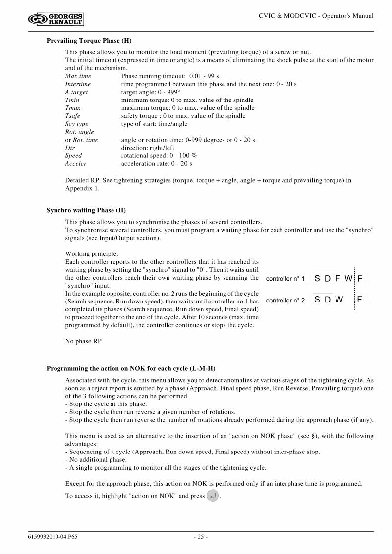
Synchro waiting Phase (H)
This phase allows you to synchronise the phases of several controllers.To synchronise several controllers, you must program a waiting phase for each controller and use the "synchro"signals (see Input/Output section).
Working principle:Each controller reports to the other controllers that it has reached itswaiting phase by setting the "synchro" signal to "0". Then it waits untilthe other controllers reach their own waiting phase by scanning the"synchro" input.In the example opposite, controller no. 2 runs the beginning of the cycle(Search sequence, Run down speed), then waits until controller no.1 hascompleted its phases (Search sequence, Run down speed, Final speed)to proceed together to the end of the cycle. After 10 seconds (max. timeprogrammed by default), the controller continues or stops the cycle.
No phase RP
Programming the action on NOK for each cycle (L-M-H)
Associated with the cycle, this menu allows you to detect anomalies at various stages of the tightening cycle. Assoon as a reject report is emitted by a phase (Approach, Final speed phase, Run Reverse, Prevailing torque) oneof the 3 following actions can be performed.- Stop the cycle at this phase.- Stop the cycle then run reverse a given number of rotations.- Stop the cycle then run reverse the number of rotations already performed during the approach phase (if any).
This menu is used as an alternative to the insertion of an "action on NOK phase" (see §), with the followingadvantages:- Sequencing of a cycle (Approach, Run down speed, Final speed) without inter-phase stop.- No additional phase.- A single programming to monitor all the stages of the tightening cycle.
Except for the approach phase, this action on NOK is performed only if an interphase time is programmed.
To access it, highlight "action on NOK" and press .
6 4 0 2 1 4 5 5 - 1 � 0 B � �
6 4 0 2 1 4 5 5 - 1 � 0 B �
� � !
� � !

- 26 -
CVIC & MODCVIC - Operator's Manual
6159932010-04.P65
3.3 - "QUICK CYCLES" Menu
This menu allows you to quickly program the cycles. By default, the quick cycles consist of a run down speed phase anda final speed phase. The operator only programs the target torque and the maximum angle on the screen.
To do so, select a cycle and press .
For the programming procedure, refer to paragraph 3.1.3.
It is the controller itself which calculates the speeds and all of the other default parameters (minimum speed, maximumspeed, etc.).According to the versions (L - M - H), it is possible to insert and program 1 or several other phases manually.
1 - Select the relevant action:- unused : the option is disabled.- stop cycle: as soon as one of the torque or angle parameters is out of tolerances at the end of one of the
phases, the cycle stops at the end of this phase.- run reverse: the cycle stops under the same circumstances as in the "stop cycle" option, then the tool
untightens the programmed number of rotations.N. rotat.: number of run reverse rotations performed by the tool in case of fault (0-100). Thevalue 0 causes a run reverse action which is equal to the number of rotations performed in theapproach phase if this phase has been programmed. Otherwise, the number of rotations isequal to 0.
Rv. speed : run reverse speed associated to an action on NOK per cycle or per phase.Thread type : right or left.
When an action on NOK phase has been programmed, it will be processed as a priority with respect to the actionon NOK of the cycle.
2 - CommentIt is possible to insert a comment (40 characters as a maximum) between the Cycle field and Number of cycles OK field
3 - Number of cycles OK
NcyclesOK number of correct cycles to activate the "NCYOK" output.
To create the phases of a cycle, place the cursor under"NcyclesOK".
Press : "Chg" is highlighted.
Press then to select the type of phase and press to validate.
Press again to describe the contents of the phase.
Press VAL to validate the changes.
To insert a phase into the list, use the "Ins" function.The new phase is inserted before the phase highlighted by the cursor.To delete a phase in the list, use the "Del" function.
- 27 -
CVIC & MODCVIC - Operator's Manual
6159932010-04.P65
3.4 - "LEARNING" Menu
First of all, select a cycle. Before performing the first tightening, enter the target torque instruction, and if required, aspeed limitation (if the tightening task does not tolerate the maximum speed of the tool: for example, to tighten in a plasticmaterial). The first tightening is performed at reduced speed, the second one is performed at faster speed, and the lasttightening allows you to finalise the programming. Once the procedure has been completed, the operator will go back to
the control screen and save the learning procedure by pressing .
According to the versions (L - M - H), it is possible to insert and program 1 or several other phases manually.
3.5 - "STATION" Menu
- FunctionsThe "STATION" menu allows you to configure the following parameters:
Screen by default Comments
NameUnit Nm Nm/Ft.Lb/In.Lb/Kg.m/Kg.cmDir direction: right/leftRv speed 50% this speed is used at each run reverse command by the operator (the run reverse speeds used
during the cycle can be programmed in the run reverse phases or in the actions on NOK percycle).
Src. cyc. keyboard source of the cycle number: peripheral used to program the current cycle: keyboard, PC, Barcode, Inputs/Outputs. (Binary programming).
Lock.NOK No lock N cycles OK: when this function is enabled, the system locks the start cycle as soon asthe number of cycles run with an accept report has reached the programmed "NCYCOK". Youmust send a Reset command to unlock the cycle start.
Scy pulse No start cycle by pulses: the "start cycle" signal can be activated with a pulse.Sp. val. No spindle validation: the spindle operation is validated or not by the PLC.SpV.rev No spindle validation at run reverse: through this function, the spindle operation is validated or
not in run reverse by the external monitoring system (via the Inputs/Outputs).Acknow No yes/no (to validate start cycle after a reject report).Cycle 0 No yes/no (to validate the running of cycle 0).RP duration 0.0 A value which is different from 0 allows you to program the pulse (0.1 to 4.0 s) reports (accept,
reject) at end of cycle.With a value equal to 0, you can program a continuous status of the reports at end of cycle.
K torque/spindle or K torque/spindleK torque/cycle. This option allows you to define:
- either 1 correction coefficient per spindle; it is stored in the tool memory. It is set to 1 bydefault and can be modified by performing the manual calibration procedure which can beaccessed from the maintenance menu. This coefficient is used to calculate the torque whateverthe cycle run.- or 1 correction coefficient per cycle; the coefficient associated to each cycle is stored in thecontroller memory, except the coefficient of cycle 0 which remains in the tool memory. It isset to 1 by default and can be modified by performing the manual calibration procedure foreach of the programmed cycles. The coefficient used to calculate the torque is the coefficientassociated to the current cycle.
Caution: It is strongly recommended NOT to program the Scy pulse option if using hand held tools.Since the tool only stops at the end of the tightening cycle, it can cause injury to the operator.
- 28 -
CVIC & MODCVIC - Operator's Manual
6159932010-04.P65
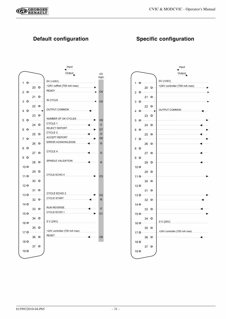
3.6 - Input / Output Configuration
3.6.1 - Overview
The "STATION" menu also allows you to reconfigure the addresses of the input and output functions on theI/O connector. According to the desired operation, you can use either the default configuration, or the dedicatedconfiguration with functions not defined in the default configuration.Except for the output SYNC signal available only on logical outputs 5 and 8, all of the other functions can beconfigured on any input or output available. You can configure the same output function on several outputs of theI/O connector.
You will find hereafter a description of the following:- Input functions.- Output functions.- The default configuration.
- 29 -
CVIC & MODCVIC - Operator's Manual
6159932010-04.P65
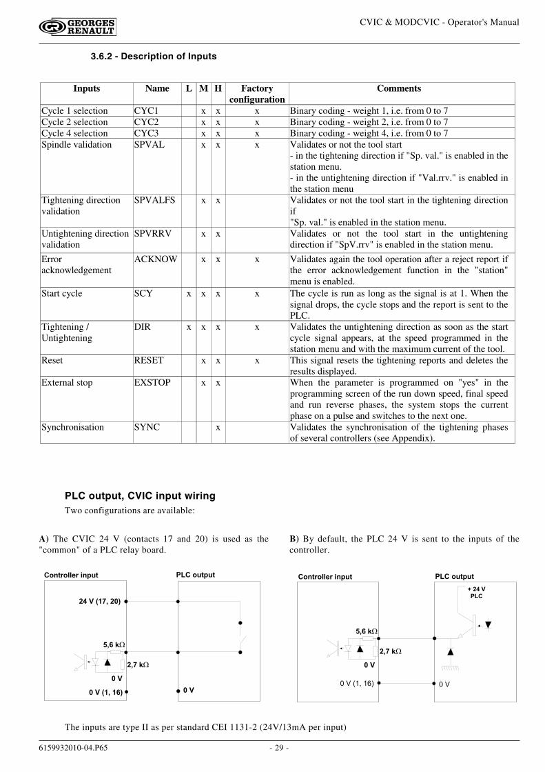
PLC output, CVIC input wiringTwo configurations are available:
A) The CVIC 24 V (contacts 17 and 20) is used as the"common" of a PLC relay board.
B) By default, the PLC 24 V is sent to the inputs of thecontroller.
" � � � � $ � � $ �� � � � % � � � % � � � � $ �
� � #
� � #� � # � & � ' � � ( )
* � # � & � + ' � � )
, ' ( � - �
' + � - �
. � * � #" � �
� � �� � � � 9 � � � � % ;
� � #
, ' ( � - �
' + � - �
" � � � � $ � � $ �� � � � % � � � % � � � � $ �
The inputs are type II as per standard CEI 1131-2 (24V/13mA per input)
3.6.2 - Description of Inputs
Inputs Name L M H Factoryconfiguration
Comments
Cycle 1 selection CYC1 x x x Binary coding - weight 1, i.e. from 0 to 7Cycle 2 selection CYC2 x x x Binary coding - weight 2, i.e. from 0 to 7Cycle 4 selection CYC3 x x x Binary coding - weight 4, i.e. from 0 to 7Spindle validation SPVAL x x x Validates or not the tool start
- in the tightening direction if "Sp. val." is enabled in thestation menu.- in the untightening direction if "Val.rrv." is enabled inthe station menu
Tightening directionvalidation
SPVALFS x x Validates or not the tool start in the tightening directionif"Sp. val." is enabled in the station menu.
Untightening directionvalidation
SPVRRV x x Validates or not the tool start in the untighteningdirection if "SpV.rrv" is enabled in the station menu.
Erroracknowledgement
ACKNOW x x x Validates again the tool operation after a reject report ifthe error acknowledgement function in the "station"menu is enabled.
Start cycle SCY x x x x The cycle is run as long as the signal is at 1. When thesignal drops, the cycle stops and the report is sent to thePLC.
Tightening /Untightening
DIR x x x x Validates the untightening direction as soon as the startcycle signal appears, at the speed programmed in thestation menu and with the maximum current of the tool.
Reset RESET x x x This signal resets the tightening reports and deletes theresults displayed.
External stop EXSTOP x x When the parameter is programmed on "yes" in theprogramming screen of the run down speed, final speedand run reverse phases, the system stops the currentphase on a pulse and switches to the next one.
Synchronisation SYNC x Validates the synchronisation of the tightening phasesof several controllers (see Appendix).
- 30 -
CVIC & MODCVIC - Operator's Manual
6159932010-04.P65
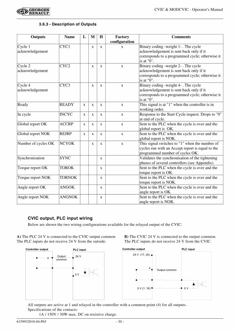
3.6.3 - Description of Outputs
CVIC output, PLC input wiringBelow are shown the two wiring configurations available for the relayed output of the CVIC:
� �
� " �
� � � � � � � � � � � � � � � � � � � �
" < 2 + < 26 4 . . 4 0 �
< 2 + < 2 � 6 4 . . 4 0"
� " � � � 9 � � � � � � ;
� � � � � � � � � � � � � � � � � � � �
� � � 9 � � � � # ; � �
A) The PLC 24 V is connected to the CVIC output commonThe PLC inputs do not receive 24 V from the outside.
B) The CVIC 24 V is connected to the output common.The PLC inputs do not receive 24 V from the CVIC.
All outputs are active at 1 and relayed in the controller with a common point (4) for all outputs.Specifications of the contacts:
1A / 150V / 30W max. DC on resistive charge.
Outputs Name L M H Factoryconfiguration
Comments
Cycle 1acknowledgement
CYC1 x x x Binary coding -weight 1- . The cycleacknowledgement is sent back only if itcorresponds to a programmed cycle; otherwise itis at "0".
Cycle 2acknowledgement
CYC2 x x x Binary coding -weight 2- . The cycleacknowledgement is sent back only if itcorresponds to a programmed cycle; otherwise itis at "0".
Cycle 4acknowledgement
CYC3 x x x Binary coding -weight 4- . The cycleacknowledgement is sent back only if itcorresponds to a programmed cycle; otherwise itis at "0".
Ready READY x x x x This signal is at "1" when the controller is inworking order.
In cycle INCYC x x x x Response to the Start Cycle request. Drops to "0"at end of cycle.
Global report OK ACCRP x x x x Sent to the PLC when the cycle is over and theglobal report is OK.
Global report NOK REJRP x x x x Sent to the PLC when the cycle is over and theglobal report is NOK.
Number of cycles OK NCYOK x x x This signal switches to "1" when the number ofcycles run with an Accept report is equal to theprogrammed number of cycles OK.
Synchronisation SYNC x Validates the synchronisation of the tighteningphases of several controllers (see Appendix)
Torque report OK TOROK x Sent to the PLC when the cycle is over and thetorque report is OK.
Torque report NOK TORNOK x Sent to the PLC when the cycle is over and thetorque report is NOK.
Angle report OK ANGOK x Sent to the PLC when the cycle is over and theangle report is OK.
Angle report NOK ANGNOK x Sent to the PLC when the cycle is over and theangle report is NOK.
- 31 -
CVIC & MODCVIC - Operator's Manual
6159932010-04.P65
� � � � � � � " � ! � � � � �
� � � � �
� � � � � � � �
� � � � � � � � �
� � � � � � � � " � � � � � � �
� � C � � � � � � � �
� � � � � � � � � �
� � � � � � � � � � �
� � � � � � � � � � $
� � � � � � � � � � � � � � � � �
� � � � �
� � � � � � � � � � �
� � � � � � � � � � �
�
�
� �
� %
� �
� #
� �
� �
� $
� �
� %
�
� �
� $
� �
� �
� �
�
� �
#
�
#
�
� �
�
%
%
�
�
$
$
�
�
�
�
< 2 + < 2
� 0 + < 2
� � � � � � � � � �
� � � � 9 $ � ;
� � � 9 ' $ � ;
' $ � � 6 4 D D 1 - 2 � 9 � � � � . � � . � E ;
� � � � � � �
� � � � � �
� � � � � � $
$
� � 5 4 3 / 6
�
#
� �
�
�
%
� �
� �
� $
�
� %
� �
�
#
' $ � � 6 4 0 2 1 4 5 5 - 1 � 9 � � � � . � � . � E ;
Default configuration Specific configuration
� � � � � � � � �
�
�
� �
� %
� �
� #
� �
� �
� $
� �
� %
�
� �
� $
� �
� �
� �
�
� �
#
�
#
�
� �
�
%
%
�
�
$
$
�
�
�
�
< 2 + < 2
� 0 + < 2
� � � � 9 $ � ;
� � � 9 ' $ � ;
' $ � � 6 4 0 2 1 4 5 5 - 1 � 9 � � � � . � � . � E ;
' $ � � 6 4 0 2 1 4 5 5 - 1 � 9 � � � � . � � . � E ;
- 32 -
CVIC & MODCVIC - Operator's Manual
6159932010-04.P65
3.7 - "PERIPHERALS" Menu
3.7.1 - Serial Port
The serial port is used for the following functions:♦Data transfer to PC,♦ Bar code and report output,♦ Printing the results in order of occurrence (ASCII)♦ Automatic calibration with the DELTA4000 measuring unit (no programming is required)
- Data transfer to PC
- Controller
The parameters used for the data transfer to PC are as follows:RS232/RS422:
RS232 default standard type used for connecting a PC and a single controllerRS422 used in a network configuration only
Baud rate from 300 to 19,200 Bauds, 7 or 8 data bits, 1 or 2 stop bits, no parity/even/oddDefault values: 19,200 Bauds, 8 data bits, 1 stop bit, no parity.
Slave no. : 0-254. In a network configuration, the PC is connected to several controllers at the sametime. The "Intermediate" or "end of line" differentiation is obtained by resistance wiring inthe connectors of the network cable. (See wiring diagrams).For further information about the network connection, refer to the "CVIPC" Operator's
Manual.
- MODCVIC
For the MODCVIC module, the switching of the communications standard RS232 / RS422 is automatic dependingon the address selected by the rotary switches:
- address 0 implies standard RS232 for the connection of a PC and a single controller- any other address selected implies standard RS422 for a network connection.
The other parameters are set to:- 19,200 bauds- 8 data bits- 1 stop bit- no parity
They cannot be programmed by the PC.In the case of a network connection, the "Intermediate" or "end of line" differentiation is obtained by resistancewiring in the connectors of the network cable. (See wiring diagrams).
3.7.2 - RP Output
The report is printed according to the following parameters:Format PC2/PC3/PC4/Specific/PC5A/PC5B/PC5CUpon request at end of cycle.(See "Printing format of tightening results" in Appendix 2)
- 33 -
CVIC & MODCVIC - Operator's Manual
6159932010-04.P65
3.7.3 - Bar Code
The bar code reader allows you to automatically select one of the cycles previously programmed in the controller.To enable the bar code reader, you need to do the following:
- declare the source of selection of the cycles as being the bar code.- configure the serial link:
- bar code function- Baud rate: 9,600 bauds- 8 data bits- 1 stop bit- no parity
- set up the table of selection of the cycles according to the bar code numbers, which can be done only withthe CVIS/CVIC PC2000 software.
After reading the bar code, the controller can perform one of the following actions:- No action --> no action is performed- Reset --> reading the code leads to an action which is identical to the Reset action.- Reset on NCYCOK --> reading the code leads to a Reset when the programmed number of cycles OK is
reached
- 34 -
CVIC & MODCVIC - Operator's Manual
6159932010-04.P65
1 - "MAINTENANCE" MENU
1.1 - "TEST" Menu
The"SPINDLE RUN" menu allows you to check the correct operation of the tool.Select the speed and rotation direction ("dir" reverser for a hand held tool or in the menu for a fixed tool) then press thetrigger for a hand held tool of EC type or press the "on" button for a fixed tool of MC or MCL type.Select "Reset" to reset the display.Select "Fan" to start the fan and check its working order.
The "INPUT/OUTPUT" menu allows you to check the status of inputs, and to test the outputs and the LEDs on the frontside.
Testing the outputs:
The cursor blinks on output 1. Press to move the cursor and to validate the box or not. The selected output is
or is not enabled. Then it is possible to check the efficiency of the status change of this output on the corresponding input,for example on the PLC. Use the same procedure to check that the Max, OK and Min LEDs glow correctly.
1.2 - "CHANNEL TEST" Menu
This menu is used to test the good working order of the controller and tool.There is a sequence of two tests: - reading the information contained in the tool memory
- checking the servodrive board
If an error arises, a message is displayed. Press to display an additional error message.
1.3 - "COUNTERS" Menu
This menu allows the maintenance technician to know the number of cycles run.The "Controller" counter shows the number of cycles run since delivery.The "Tot." (total) and "Par."(partial) counters show the number of cycles run by the tool.Select the "Reset" key to reset the partial counter of the tool.
SECTION 7 - MAINTENANCE OF THE CVIC CONTROLLER
This section helps the maintenance operator to:- check that the controller+tool assembly operates correctly.- know the number of cycles run.- calibrate the system manually or automatically- adjust the contrast of the display, update controller date, select the language and program an access code.- change the memory battery.
- 35 -
CVIC & MODCVIC - Operator's Manual
6159932010-04.P65
1.4 - "CALIBRATION" Menu
The calibration procedure is recommended to compensate for any possible drift of the tool torque or after each changeof tool element.
1.4.1 - "AUTO SPINDLE" Menu
Important: the tool will be calibrated over its entire operating torque range.Equipment required: - a torque measuring unit DELTA4000 connected to the CVIC controller via a serialcable.
- the tool to be calibrated with a transducer and its cable.
Program the measuring unit by pressing / to display "standard" in the summary line then to display
"Calib CVIC".
Select the type of transducer to be used by pressing then / .
If the measuring unit is not correctly connected or programmed, an error message "Check connection" is displayedon the screen.Follow the instructions displayed on the CVIC screen. 10 tests can be run and they are performed at variousincreasing speeds. Run one test after another. WARNING: the tightening is performed up to the MAX. torque.
Press VAL to validate the writing in the tool memory.
1.4.2 - "MANU SPINDLE" Menu
This menu is used to manually calibrate the tool to the torque value of the selected cycle. The torque transducerinserted in line with the tool can be connected to any measuring unit in the GEORGES RENAULT range. Run atightening cycle 5 times and manually enter the values read on the standard instrument.
Warning: the torque and angle reports MUST be correct to allow the procedure to be processed in normalconditions.
The "Reset val" key resets the readings.The "Reset coeff" key displays coefficient 1 by default.Depending on the option selected (K torque/spindle or K torque/cycle) in the "STATION" menu (see § 3.5 page 27),the sensitivity correction coefficient is saved:
- either in the tool memory- or in the controller
- 36 -
CVIC & MODCVIC - Operator's Manual
6159932010-04.P65
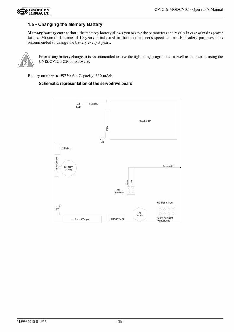
1.5 - Changing the Memory Battery
Memory battery connection : the memory battery allows you to save the parameters and results in case of mains powerfailure. Maximum lifetime of 10 years is indicated in the manufacturer's specifications. For safety purposes, it isrecommended to change the battery every 5 years.
Prior to any battery change, it is recommended to save the tightening programmes as well as the results, using theCVIS/CVIC PC2000 software.
Battery number: 6159229060. Capacity: 550 mA/h
C $ � � / , + 5 � 7C �� � �
C � � - = < 3
C�$�"-7=4�1>
C � �� �
C � � � 0 + < 2 � < 2 + < 2 C � � � � � � $
C %� 4 2 4 1
C � � � � � / 0 , � / 0 + < 2
C � �� � + � 6 / 2 4 1
��
� � � � � � � � "
� - . 4 1 7= � 2 2 - 1 7
2 4 � . � / 0 , � 4 < 2 5 - 2 �8 / 2 ( � � D < , - ,
=5�6:
1->
2 4 � 6 � + � 6 / 2 4 1
*'
C �
Schematic representation of the servodrive board
- 37 -
CVIC & MODCVIC - Operator's Manual
6159932010-04.P65
2 - "SERVICE" MENU
2.1 - "CONTRAST" Menu
Press or to adjust the contrast of the display.
When the adjustment of the contrast is such that it no longer allows you to display the menus, the following procedureallows you to activate the contrast menu when switching on:
- Switch off the controller.
- Press VAL and simultaneously switch on the controller.
- Release the VAL key as soon as the Led blinks and the buzzer is active.
Then the "Contrast" menu is enabled. Press and to set the ajustment, then press to validate.
2.2 - "DATE" Menu
Three date formats are available: DD/MM/YY, MM/DD/YY, YY/MM/DDRefer to the start-up to see the programming details.
2.3 - "LANGUAGE" Menu
Refer to the start-up to see the programming details.
2.4 - "ACCESS CODE" Menu
The access code is used to protect the controller against any keying error.
At the time of delivery, no code is programmed; the icon is displayed on the screen.
Enter the new code (8 alphanumerical characters as a maximum), using the and keys to write and the and
keys to move the cursor. Press to validate.
Lock access by entering your code again. The padlock icon will lock , meaning that writing is prohibited. If an access
code has been programmed and the operator wants to change the data stored, it is necessary to enter the code each timethe controller is switched on.
- 38 -
CVIC & MODCVIC - Operator's Manual
6159932010-04.P65
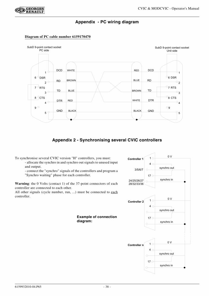
Appendix - PC wiring diagram
Diagram of PC cable number 6159170470
�
#
�
%
�
$
�
�
� �
� �� � �
� � �
� � �� � �
� � �
� � � � � �
� �
� �
� � �
� � �
� � �
� � �
� � �%
�
#
�
�
�
$
�� � � � "
! � � � �
� � ! �
� � � �
� � �
� < = � � � * + 4 / 0 2 � 6 4 0 2 � 6 2 � , 4 6 : - 2 � � , / > -
� < = � � � * + 4 / 0 2 � 6 4 0 2 � 6 2 � , 4 6 : - 2� 0 / 2 � , / > -
� � � � "
! � � � �
� � ! �
� � � �
� � �
Appendix 2 - Synchronising several CVIC controllers
To synchronise several CVIC version "H" controllers, you must:- allocate the synchro in and synchro out signals to unused inputand output.- connect the "synchro" signals of the controllers and program a"Synchro waiting" phase for each controller.
Warning: the 0 Volts (contact 1) of the 37-point connectors of eachcontroller are connected to each other.All other signals (cycle number, run, ...) must be connected to eachcontroller.
Example of connectiondiagram:
�
� �
� � �
, 7 0 6 ( 1 4 � / 0
� � � � % � � � % � �
$
� � � � % � �
$ � � � % � � # � � � � � � � %
, 7 0 6 ( 1 4 � 4 < 2
�
� �
� � �
, 7 0 6 ( 1 4 � / 0
� � � � % � � � % �
$
, 7 0 6 ( 1 4 � 4 < 2
�
� �
� � �
, 7 0 6 ( 1 4 � / 0
� � � � % � � � % � �
$
, 7 0 6 ( 1 4 � 4 < 2
- 39 -
CVIC & MODCVIC - Operator's Manual
6159932010-04.P65
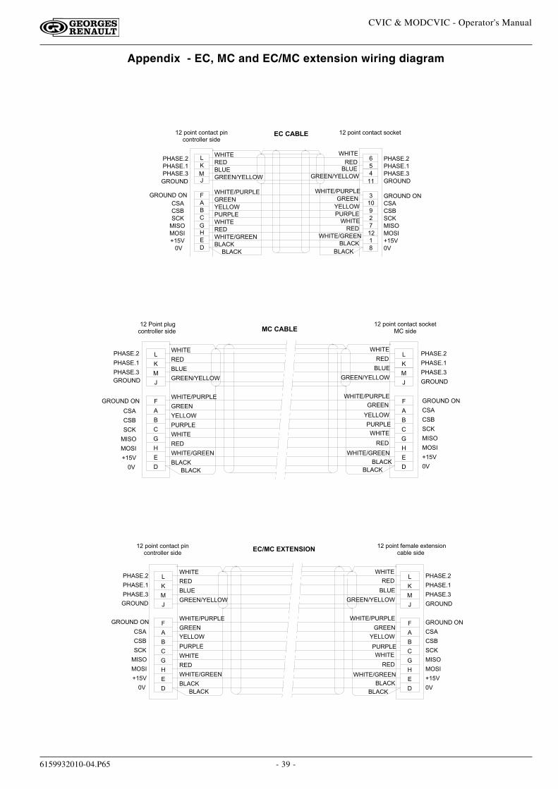
Appendix - EC, MC and EC/MC extension wiring diagram
$� � � � � ) � � � � � ) �� � � � � � � � � � !
! � � � � � � � � �
� � � �
� � � � !
! � � � �
� � �
! � � � � � � � � � �
� � � � "
� � � � �
�� � �
� � �
� �
' � � �
�
�
�
� � � � �
� � � � � � �
� � �
� � �
� � "
�
�
�
C
! � � � � � � � � � �
� � � � "
� � � � "
� � �
� � � � � � � � � � !
! � � � � � � � � �
� � � � �
� � � � !
� � � �
! � � � �
� � � � "
� � � �
�
�
#
' � � �
� �
� � �
� �
�
� �
�
� � �
� � �
� � "
� � � � �
� � � � � � �
� � + 4 / 0 2 � 6 4 0 2 � 6 2 � , 4 6 : - 2
� � �
! � � � �
� � � �
� � + 4 / 0 2 � 6 4 0 2 � 6 2 � + / 06 4 0 2 1 4 5 5 - 1 � , / > -
� � � � ) �
� � � � ) �
"� � � �
� � �
! � � � �
�
%
� � � � ) �
� � � � )
� � � � � � � �
� � � � )
� � � � ) �
� � � 4 / 0 2 � + 5 < 36 4 0 2 1 4 5 5 - 1 � , / > -
� � � � �
� � �
� � �
� � � � � � �
� � "
� � �
� �
' � � �
� � �
� � � � ) �
� � �
! � � � � � � � � � �
� � � � "
�
�
�
� � � � "
! � � � �
� � �
! � � � � � � � � �
� � � � � � � � � � !
� � � � !
! � � � �
� � � ��
�
�
�� � � � �
C
�
�
"� � � �
� � �
' � � �
� � �
� � � � "
! � � � � � � � � � �
� � � � "
�
�
�
� �
� � � + 4 / 0 2 � 6 4 0 2 � 6 2 � , 4 6 : - 2� � � � , / > -
� � � � )
� � � � ) �
� � � � �
� � �
� � � � � � �
� � � � ) �
! � � � �
� � �
� � � � �
� � � � !
! � � � �
� � � �
� � � �
! � � � � � � � � �
� � � � � � � � � � !
�
�
�
�
� � �
� � "
� � �
C
�
�
"
� / � � � � � � � �
� � + 4 / 0 2 � 6 4 0 2 � 6 2 � + / 06 4 0 2 1 4 5 5 - 1 � , / > -
' � � �
� �
�
�
� � � � ) �
� � � � )
� � � � ) �
� � � � � � �
� � �
� � �
� � "
� � �
� � �
�
�
�
�
�
� � � � �
�
C
"
�
! � � � � � � � � �
! � � � � � � � � � �
� � � � � � � � � � !
� � � � "
! � � � � � � � � � �
� � � � "
! � � � � � � � � �
� � � �
� � �
! � � � �
� � � � !
� � � � �
� � � � � � � � � � !
! � � � �
� � � �
� � �
� � � � "
� � � � "�
�
' � � �
� �
� � � �
� � �
! � � � �
� � � � !
� � � � �
�
�
�
�
�
� � � �
� � �
! � � � �
�
C
�
"
� � � � � � �
� � �
� � �
� � "
� � �
� � �
� � � � ) �
� � � � )
� � � � ) �
� � � � �
� � � + 4 / 0 2 � D - . � 5 - � - E 2 - 0 , / 4 06 � = 5 - � , / > -
� � � 0 / � � � 1 � � � � � � �

APPENDIX 1 - TIGHTENING STRATEGIES
- 47 -D:\PAO\ANNEXES\ANGLAIS\ANNEXE1-00.P65
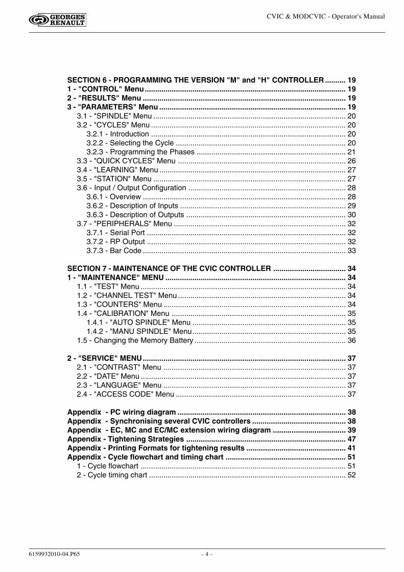
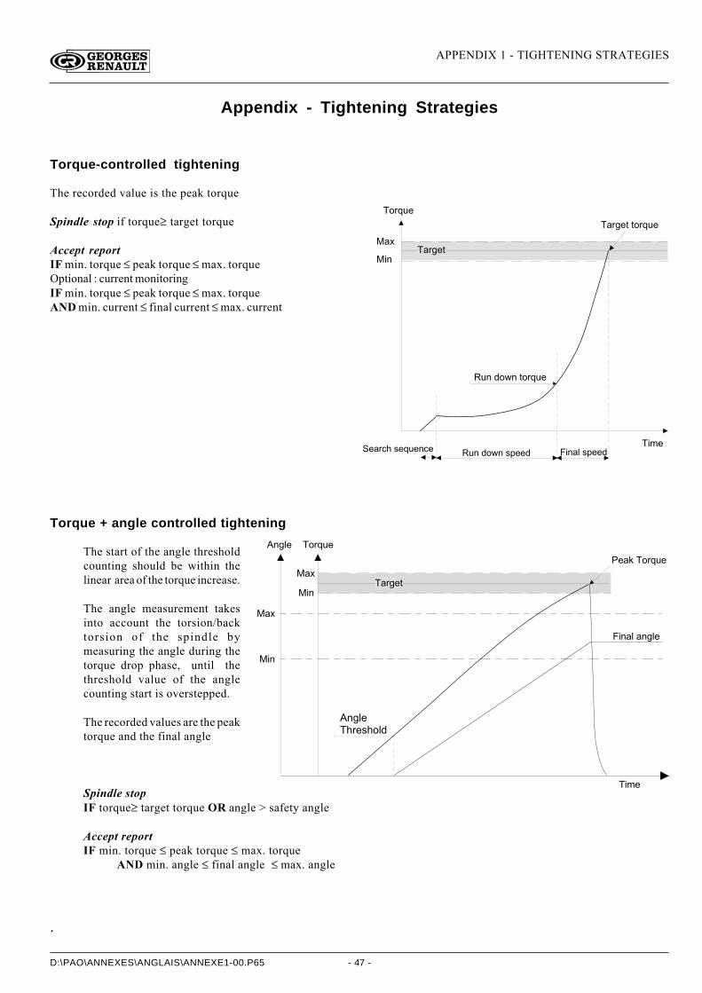
Torque-controlled tightening
The recorded value is the peak torque
Spindle stop if torque≥ target torque
Accept reportIF min. torque ≤ peak torque ≤ max. torqueOptional : current monitoringIF min. torque ≤ peak torque ≤ max. torqueAND min. current ≤ final current ≤ max. current
� 5 2 @ = /
� � 2 4 / 3 � 3 5 2 @ = /
� 0 � /
� 0 1
� � E� � 2 4 / 3
� / � 2 7 + � . / @ = / 1 7 / � = 1 � ? 5 9 1 � . - / / ? % 0 1 � 6 � . - / / ?
� = 1 � ? 5 9 1 � 3 5 2 @ = /
Torque + angle controlled tightening
The start of the angle thresholdcounting should be within thelinear area of the torque increase.
The angle measurement takesinto account the torsion/backtorsion of the spindle bymeasuring the angle during thetorque drop phase, until thethreshold value of the anglecounting start is overstepped.
The recorded values are the peaktorque and the final angle
Spindle stopIF torque≥ target torque OR angle > safety angle
Accept reportIF min. torque ≤ peak torque ≤ max. torque
AND min. angle ≤ final angle ≤ max. angle
� � 2 4 / 3
� / � ; � � 5 2 @ = /
% 0 1 � 6 � � 1 4 6 /
� 0 � /
� 1 4 6 / � 5 2 @ = /
� � E
� 0 1
� � E
� 0 1
� 1 4 6 / �� + 2 / . + 5 6 ?
.
Appendix - Tightening Strategies
APPENDIX 1 - TIGHTENING STRATEGIES
- 48 -D:\PAO\ANNEXES\ANGLAIS\ANNEXE1-00.P65
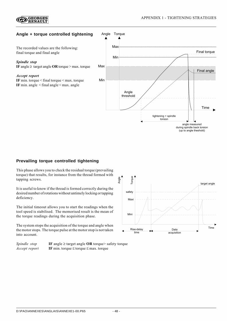
Angle + torque controlled tightening
The recorded values are the following:final torque and final angle
Spindle stopIF angle ≥ target angle OR torque > max. torque
Accept reportIF min. torque < final torque < max. torqueIF min. angle < final angle < max. angle
� 1 4 6 /3 + 2 / . + 5 6 ?
� 0 � /
� 1 4 6 /
3 0 4 + 3 / 1 0 1 4 � * � . - 0 1 ? 6 /3 5 2 . 0 5 1 �
% 0 1 � 6 � 3 5 2 @ = /
% 0 1 � 6 � � 1 4 6 /
� 1 4 6 / � � / � . = 2 / ?? = 2 0 1 4 � . - 0 1 ? 6 / � > � 7 ; � 3 5 2 . 0 5 1
: = - � 3 5 � � 1 4 6 / � 3 + / . + 5 6 ? <
� 5 2 @ = /
� � E
� 0 1
� � E
� 0 1
Prevailing torque controlled tightening
This phase allows you to check the residual torque (prevailingtorque) that results, for instance from the thread formed withtapping screws.
It is useful to know if the thread is formed correctly during thedesired number of rotations without untimely locking or tappingdeficiency.
The initial timeout allows you to start the readings when thetool speed is stabilised. The memorised result is the mean ofthe torque readings during the acquisition phase.
The system stops the acquisition of the torque and angle whenthe motor stops. The torque pulse at the motor stop is not takeninto account.
Spindle stop IF angle ≥ target angle OR torque> safety torqueAccept report IF min. torque ≤ torque ≤ max. torque
�146/
� 0 � /� 0 . / , ? / 6 � 8
3 0 � /� � 3 �
� 7 @ = 0 . 0 3 0 5 1
. � D / 3 8
� � E 0
3 � 2 4 / 3 � � 1 4 6 /
� 0 1 0
�52@=/
APPENDIX 1 - TIGHTENING STRATEGIES
- 49 -D:\PAO\ANNEXES\ANGLAIS\ANNEXE1-00.P65
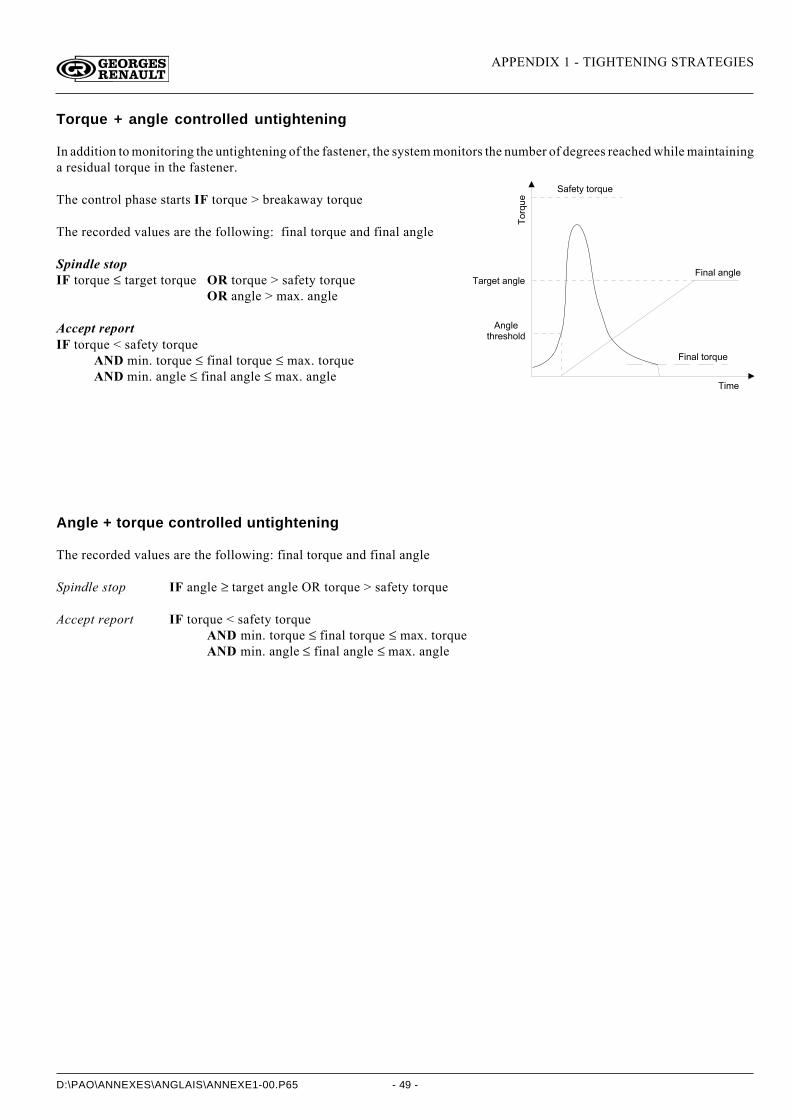
Torque + angle controlled untightening
In addition to monitoring the untightening of the fastener, the system monitors the number of degrees reached while maintaininga residual torque in the fastener.
The control phase starts IF torque > breakaway torque
The recorded values are the following: final torque and final angle
Spindle stopIF torque ≤ target torque OR torque > safety torque
OR angle > max. angle
Accept reportIF torque < safety torque
AND min. torque ≤ final torque ≤ max. torqueAND min. angle ≤ final angle ≤ max. angle
Angle + torque controlled untightening
The recorded values are the following: final torque and final angle
Spindle stop IF angle ≥ target angle OR torque > safety torque
Accept report IF torque < safety torqueAND min. torque ≤ final torque ≤ max. torqueAND min. angle ≤ final angle ≤ max. angle
� 0 � /
�52@=/
� � 2 4 / 3 � � 1 4 6 /
� 1 4 6 /3 + 2 / . + 5 6 ?
� � D / 3 8 � 3 5 2 @ = /
% 0 1 � 6 � � 1 4 6 /
% 0 1 � 6 � 3 5 2 @ = /

APPENDIX 1 - TIGHTENING STRATEGIES
- 50 -D:\PAO\ANNEXES\ANGLAIS\ANNEXE1-00.P65
APPENDIX - PRINTING FORMATS FOR TIGHTENING RESULTS
- 41 -D:\PAO\ANNEXES\ANGLAIS\ANNEXE2-00.P65
Appendix - Printing Formats for tightening results
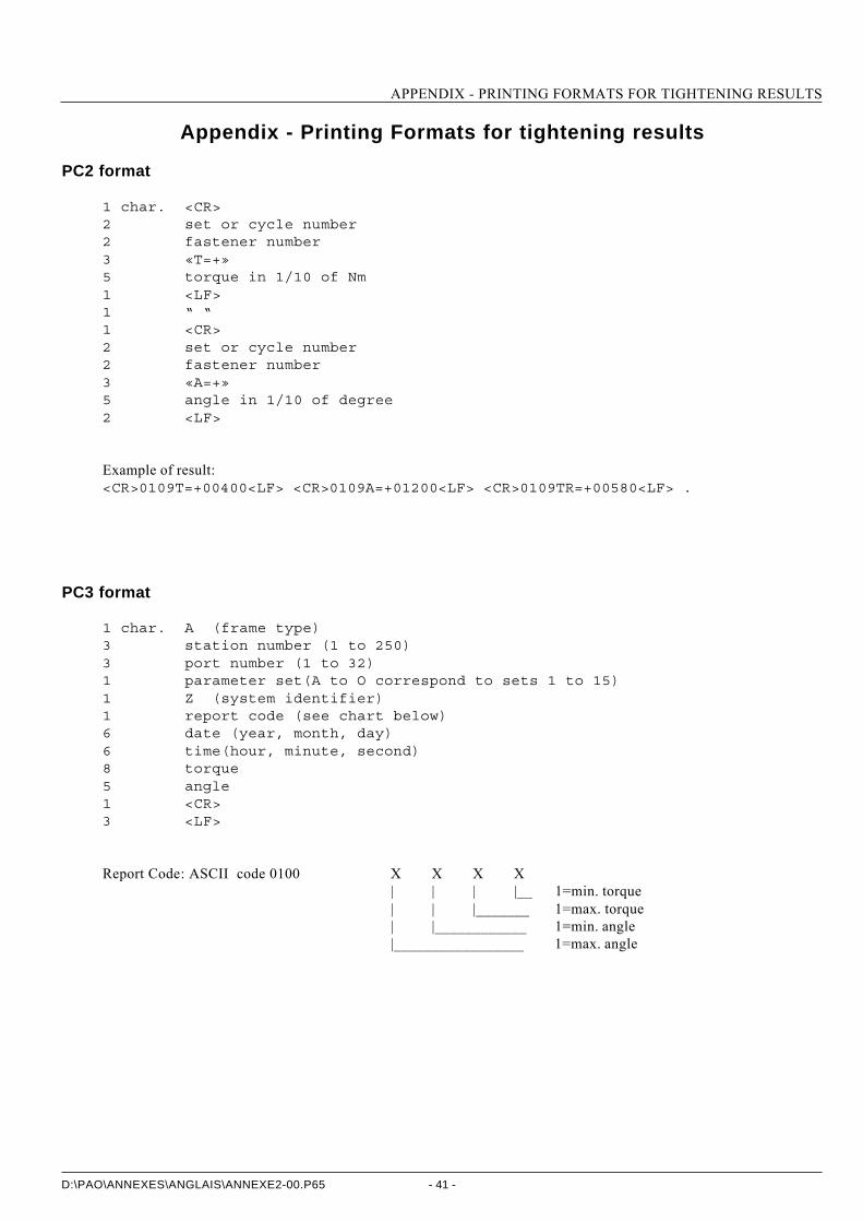
PC2 format
1 char. <CR>2 set or cycle number2 fastener number3 «T=+»5 torque in 1/10 of Nm1 <LF>1 “ “1 <CR>2 set or cycle number2 fastener number3 «A=+»5 angle in 1/10 of degree2 <LF>
Example of result:<CR>0109T=+00400<LF> <CR>0109A=+01200<LF> <CR>0109TR=+00580<LF> .
PC3 format
1 char. A (frame type)3 station number (1 to 250)3 port number (1 to 32)1 parameter set(A to O correspond to sets 1 to 15)1 Z (system identifier)1 report code (see chart below)6 date (year, month, day)6 time(hour, minute, second)8 torque5 angle1 <CR>3 <LF>
Report Code: ASCII code 0100 X X X X| | | |__ 1=min. torque| | |_______ 1=max. torque| |____________ 1=min. angle|_________________ 1=max. angle
APPENDIX - PRINTING FORMATS FOR TIGHTENING RESULTS
- 42 -D:\PAO\ANNEXES\ANGLAIS\ANNEXE2-00.P65
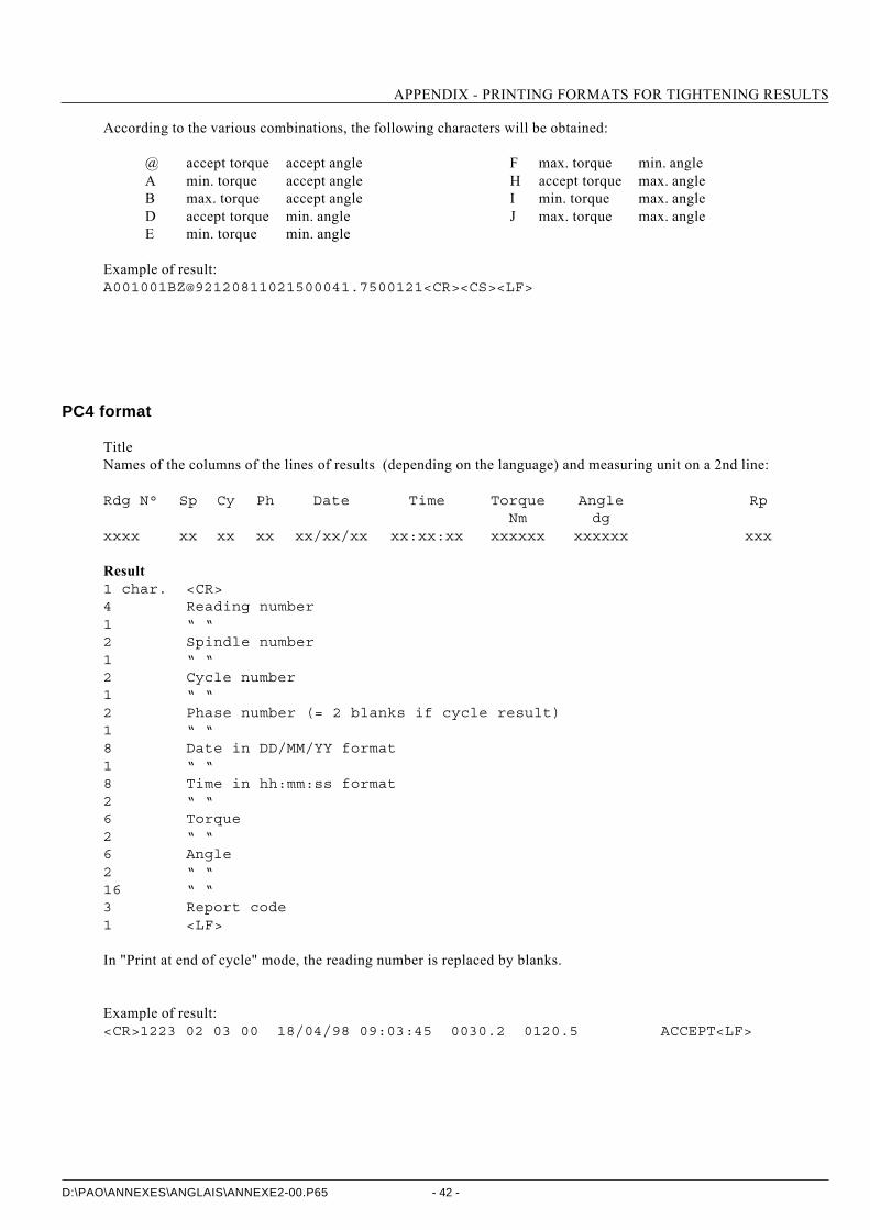
According to the various combinations, the following characters will be obtained:
@ accept torque accept angle F max. torque min. angleA min. torque accept angle H accept torque max. angleB max. torque accept angle I min. torque max. angleD accept torque min. angle J max. torque max. angleE min. torque min. angle
Example of result:[email protected]<CR><CS><LF>
PC4 format
TitleNames of the columns of the lines of results (depending on the language) and measuring unit on a 2nd line:
Rdg N° Sp Cy Ph Date Time Torque Angle RpNm dg
xxxx xx xx xx xx/xx/xx xx:xx:xx xxxxxx xxxxxx xxx
Result1 char. <CR>4 Reading number1 “ “2 Spindle number1 “ “2 Cycle number1 “ “2 Phase number (= 2 blanks if cycle result)1 “ “8 Date in DD/MM/YY format1 “ “8 Time in hh:mm:ss format2 “ “6 Torque2 “ “6 Angle2 “ “16 “ “3 Report code1 <LF>
In "Print at end of cycle" mode, the reading number is replaced by blanks.
Example of result:<CR>1223 02 03 00 18/04/98 09:03:45 0030.2 0120.5 ACCEPT<LF>
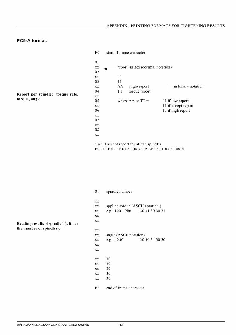
APPENDIX - PRINTING FORMATS FOR TIGHTENING RESULTS
- 43 -D:\PAO\ANNEXES\ANGLAIS\ANNEXE2-00.P65
PC5-A format:
F0 start of frame character
01xx report (in hexadecimal notation):02xx 0003 11xx AA angle report in binary notation04 TT torque reportxx05 where AA or TT = 01 if low reportxx 11 if accept report06 10 if high reportxx07xx08xx
e.g.: if accept report for all the spindlesF0 01 3F 02 3F 03 3F 04 3F 05 3F 06 3F 07 3F 08 3F
01 spindle number
xxxx applied torque (ASCII notation )xx e.g.: 100.1 Nm 30 31 30 30 31xxxx
xxxx angle (ASCII notation)xx e.g.: 40.0° 30 30 34 30 30xxxx
xx 30xx 30xx 30xx 30xx 30
FF end of frame character
Report per spindle: torque rate,torque, angle
Reading results of spindle 1 (x timesthe number of spindles):
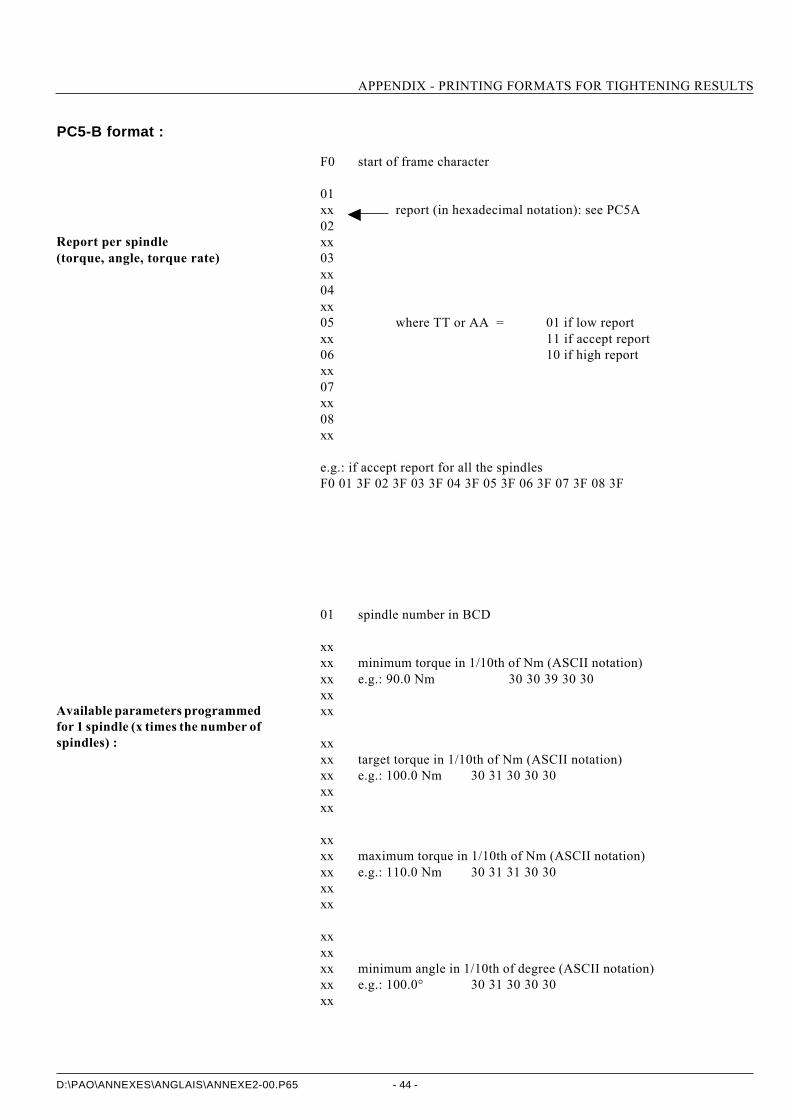
APPENDIX - PRINTING FORMATS FOR TIGHTENING RESULTS
- 44 -D:\PAO\ANNEXES\ANGLAIS\ANNEXE2-00.P65
PC5-B format :
F0 start of frame character
01xx report (in hexadecimal notation): see PC5A02xx03xx04xx05 where TT or AA = 01 if low reportxx 11 if accept report06 10 if high reportxx07xx08xx
e.g.: if accept report for all the spindlesF0 01 3F 02 3F 03 3F 04 3F 05 3F 06 3F 07 3F 08 3F
01 spindle number in BCD
xxxx minimum torque in 1/10th of Nm (ASCII notation)xx e.g.: 90.0 Nm 30 30 39 30 30xxxx
xxxx target torque in 1/10th of Nm (ASCII notation)xx e.g.: 100.0 Nm 30 31 30 30 30xxxx
xxxx maximum torque in 1/10th of Nm (ASCII notation)xx e.g.: 110.0 Nm 30 31 31 30 30xxxx
xxxxxx minimum angle in 1/10th of degree (ASCII notation)xx e.g.: 100.0° 30 31 30 30 30xx
Report per spindle(torque, angle, torque rate)
Available parameters programmedfor 1 spindle (x times the number ofspindles) :
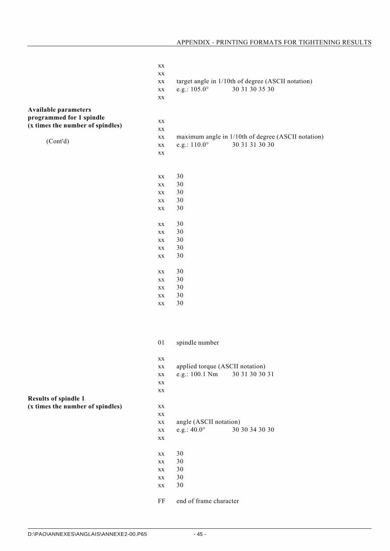
APPENDIX - PRINTING FORMATS FOR TIGHTENING RESULTS
- 45 -D:\PAO\ANNEXES\ANGLAIS\ANNEXE2-00.P65
xxxxxx target angle in 1/10th of degree (ASCII notation)xx e.g.: 105.0° 30 31 30 35 30xx
xxxxxx maximum angle in 1/10th of degree (ASCII notation)xx e.g.: 110.0° 30 31 31 30 30xx
xx 30xx 30xx 30xx 30xx 30
xx 30xx 30xx 30xx 30xx 30
xx 30xx 30xx 30xx 30xx 30
01 spindle number
xxxx applied torque (ASCII notation)xx e.g.: 100.1 Nm 30 31 30 30 31xxxx
xxxxxx angle (ASCII notation)xx e.g.: 40.0° 30 30 34 30 30xx
xx 30xx 30xx 30xx 30xx 30
FF end of frame character
Results of spindle 1(x times the number of spindles)
Available parametersprogrammed for 1 spindle(x times the number of spindles)
(Cont'd)

APPENDIX - PRINTING FORMATS FOR TIGHTENING RESULTS
- 46 -D:\PAO\ANNEXES\ANGLAIS\ANNEXE2-00.P65
Format PC5-C :
F0 start of frame character
01 spindle number (CVIC 1)xx report (in hexadecimal notation as for PC5-A and PC5-B) :
FF End of frame.
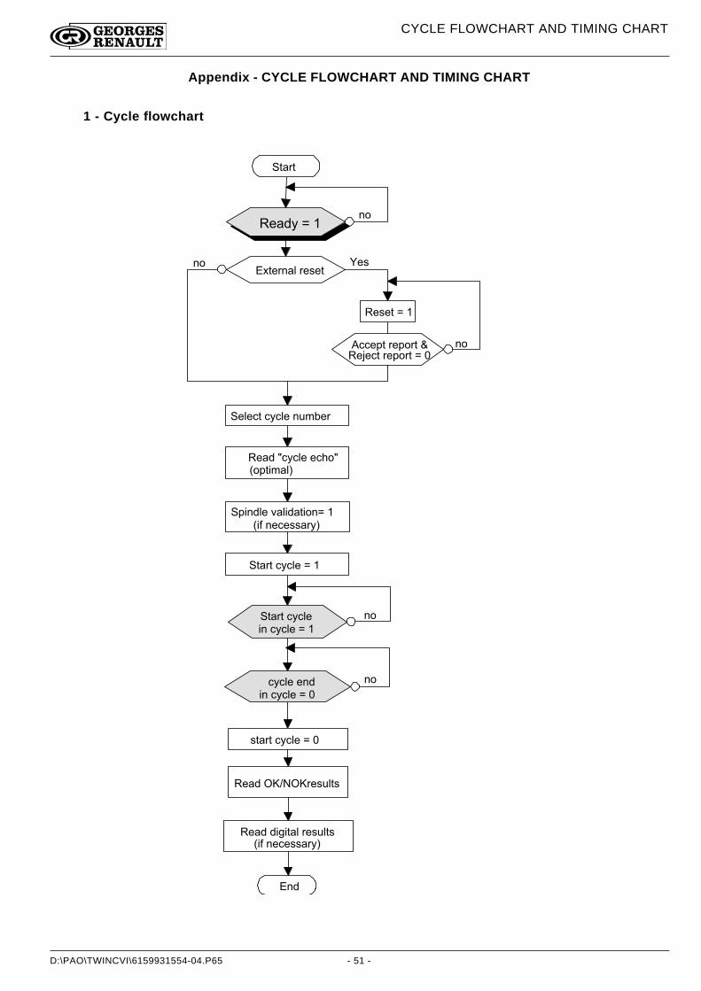
D:\PAO\TWINCVI\6159931554-04.P65
CYCLE FLOWCHART AND TIMING CHART
- 51 -
Appendix - CYCLE FLOWCHART AND TIMING CHART
1 - Cycle flowchart
� 3 � 2 3 �
� / � ? 8 � F � � �
� / 6 / 7 3 � 7 8 7 6 / � 1 = � > / 2
� / � ? � G 7 8 7 6 / � / 7 + 5 G �: 5 - 3 0 � � 6 < �
� - 0 1 ? 6 / � A � 6 0 ? � 3 0 5 1 F � � �: 0 D � 1 / 7 / . . � 2 8 < �
� 3 � 2 3 � 7 8 7 6 / � F � � �
7 8 7 6 / � / 1 ?0 1 � 7 8 7 6 / � F � � �
. 3 � 2 3 � 7 8 7 6 / � F � � �
� / � ? � � ' � � � ' 2 / . = 6 3 . �
1 ?
� 3 � 2 3 � 7 8 7 6 / �0 1 � 7 8 7 6 / � F � � �
E 3 / 2 1 � 6 � 2 / . / 3
� / . / 3 � F � � �
� 7 7 / - 3 � 2 / - 5 2 3 � H � �� / I / 7 3 � 2 / - 5 2 3 � F � � �
� / . �1 5 �
1 5 �
1 5 �
1 5
1 5 �
� / � ? � ? 0 4 0 3 � 6 � 2 / . = 6 3 . � �: 0 D � 1 / 7 / . . � 2 8 < �
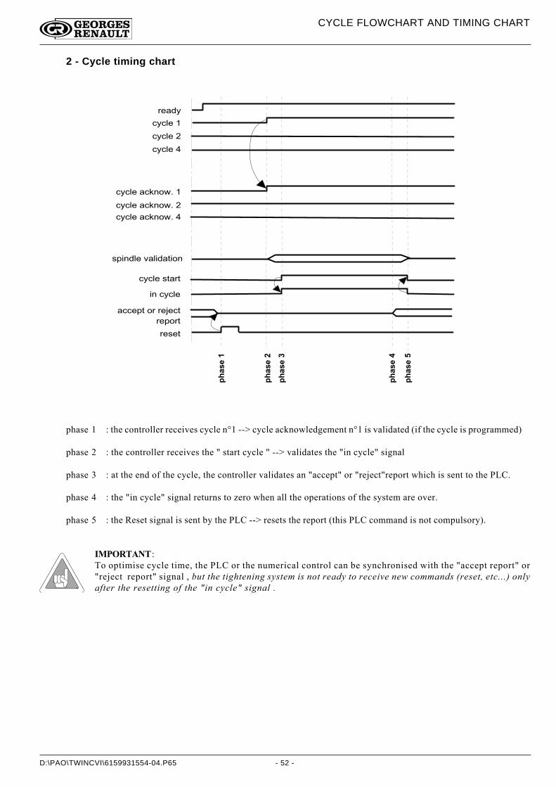
D:\PAO\TWINCVI\6159931554-04.P65
CYCLE FLOWCHART AND TIMING CHART
- 52 -
2 - Cycle timing chart
�2�� �
�2�� �3
�2�� �*
�2�� �,
�2�� ��
2 / � ? 8
7 8 7 6 / � �
7 8 7 6 / � �
7 8 7 6 / � (
� 7 8 7 6 / � � 7 ; 1 5 9 � � �
7 8 7 6 / � � 7 ; 1 5 9 � � �
7 8 7 6 / � � 7 ; 1 5 9 � � (
. - 0 1 ? 6 / � A � 6 0 ? � 3 0 5 1
7 8 7 6 / � . 3 � 2 3
0 1 � 7 8 7 6 /
� 7 7 / - 3 � 5 2 � 2 / I / 7 3
2 / - 5 2 3
2 / . / 3
phase 1 : the controller receives cycle n°1 --> cycle acknowledgement n°1 is validated (if the cycle is programmed)
phase 2 : the controller receives the " start cycle " --> validates the "in cycle" signal
phase 3 : at the end of the cycle, the controller validates an "accept" or "reject"report which is sent to the PLC.
phase 4 : the "in cycle" signal returns to zero when all the operations of the system are over.
phase 5 : the Reset signal is sent by the PLC --> resets the report (this PLC command is not compulsory).
IMPORTANT :To optimise cycle time, the PLC or the numerical control can be synchronised with the "accept report" or"reject report" signal , but the tightening system is not ready to receive new commands (reset, etc...) onlyafter the resetting of the "in cycle" signal .
![NL 5 Beatrix Clerckx [Read-Only] - fresubin.be · Cumulative proportion weaned alive from MV Cumulative proportion discharged alive from ICU Cumulative proportion discharged alive](https://img.pdfslide.net/doc/110x75/5d03708c88c9936e148b4f75/nl-5-beatrix-clerckx-read-only-cumulative-proportion-weaned-alive-from-mv.jpg)