Embed Size (px)
Citation preview
StaCast - New Quality and Design Standards for Aluminium Alloys Cast Products FP7-NMP-2012-CSA-6 - PROJECT N. 319188
www.stacast-project.org
StaCast: New Quality and Design Standards for Aluminium Alloys Cast Products – Deliverable D2.1: Database on Defetcs Authors: F. Bonollo, G. Timelli, E. Fiorese, E. Gariboldi, P. Parona, L. Arnberg
1
COORDINATION AND SUPPORT ACTION
(SUPPORTING)
Call: FP7-NMP-2012-CSA-6 Support for standardisation needs
Project full title: New Quality and Design Standards for Aluminium Alloys Cast Products
Project acronym: StaCast
Co-ordinator name Franco BONOLLO Co-ordinator organisation name University of Padova – DTG
Co-ordinator email and fax [email protected] +39 0444 998889 Co-ordinator phone + 39 0444 998743
DELIVERABLE D2.1
Database on Defects
AUTHORS: F. BONOLLO, G. TIMELLI , E. FIORESE (UNIVERSITY OF PADOVA – DTG) E. GARIBOLDI, P. PARONA (ITALIAN ASSOCIATION OF METALLURGY – AIM) L. ARNBERG (UNIVERSITY OF TRONDHEIM – NTNU)
Date: March 29th, 2013

StaCast - New Quality and Design Standards for Aluminium Alloys Cast Products FP7-NMP-2012-CSA-6 - PROJECT N. 319188
www.stacast-project.org
StaCast: New Quality and Design Standards for Aluminium Alloys Cast Products – Deliverable D2.1: Database on Defetcs Authors: F. Bonollo, G. Timelli, E. Fiorese, E. Gariboldi, P. Parona, L. Arnberg
2
Database on Defects
1. Introduction Defects are intrinsically generated by casting processes, due to several reasons. The final properties and in-service behaviour of castings are always related to microstructural features and to defects: both microstructure and defects are the results of process stages, alloys properties and dies & tools design. As an example, it should be considered that in HPDC filling stage extreme conditions are established: complexity of components leads to complex dies, and the high production rates required (up to 120 shots/h) lead to very high filling velocities for the molten alloy (up to 40 m/s) with strong generation of turbulence in the flow. Solidification takes place in few seconds, and the die is first in contact with a molten alloy at more than 700°C and, after 30-40 seconds, with a sprayed lubricant at room temperature. For these reasons HPDC (as well as other Aluminium alloys casting processes, such as permanent mold casting process) can be considered a “defect generating process”. Not only an average 5-10% scrap is typically produced, but the type, size and severity of defects are varying. From these considerations, it seems that the potential of high-pressure die-casting and permanent mold casting processes will be completely exploited only when the quality level will be perfectly optimised. In this regard, the analysis of defects allows the foundry to monitor the products quality respect to a quality standard. Further, the analysis of defects provide to the foundry useful correlations between defects type/distribution and their origin, so that it could be possible to define process modification for improving the quality. One of the current targets of the StaCast project is the compilation and dissemination of common tools to allow foundries to define a proper, comparable, quality standard. The first tool to be proposed is a common basis of language, i.e. a terminology and classification of defects in order to help die-casting foundries to face with increased confidence and ability the defect-related issues, to assure quality and reliability of their products.
2. The path towards a new Standard on Defect Classification 2.1. Previous classifications of defects There are three main approaches for defects classification of cast components proposed in literature or currently adopted by foundries:
- Cocks approach based on defects geometry/location - Campbell approach based on defects metallurgical origin/causes - NADCA approach based on defects morphology.
The first approach was proposed by Cocks and discerns between surface and internal defects (Table 1). The surface defects are visible by naked eye and impact both on the product aesthetics and functionality. On the other hand, the internal defects influence only the in-service properties of the component. As shown in Table 2, the second approach, proposed by Campbell, classifies defects on the basis of their metallurgical origin/causes (casting geometry, cast alloy, die characteristics, die lubrication, process parameters, etc.). The main advantage offered by this classification is the opportunity to design and adopt strategies to improve products quality. The main disadvantage of this approach is that the origin/causes of the defect must be defined concurrently to defect identification and that a single defect can be due to several concurring factors. Further, this approach is less suitable for
StaCast - New Quality and Design Standards for Aluminium Alloys Cast Products FP7-NMP-2012-CSA-6 - PROJECT N. 319188
www.stacast-project.org
StaCast: New Quality and Design Standards for Aluminium Alloys Cast Products – Deliverable D2.1: Database on Defetcs Authors: F. Bonollo, G. Timelli, E. Fiorese, E. Gariboldi, P. Parona, L. Arnberg
3
direct application in foundries with respect to geometry/position-based approaches, where specific inspections can be proposed to reveal different defect groups. The third approach was proposed by NADCA (North America Die Casting Association) and is based on defects morphology. NADCA suggested seven defects categories, that are indicated by a letter (Table 3). Each category is divided into groups, that are divided into subgroups.
Category Class Type 1-General 2-Splash and shotting 3-Vortex
1-Cold shut
4-Lamination 1-Blisters 2-Sinks 2-Smooth irregularities 3-Lakes 1-Drag marks
1-Surface defects
3-Rough surface 2-Solder 1-Hydrogen
1-Gas porosity 2-Oxidizing gases 1-Gross 2-Intergranular
Coc
ks c
lass
ifica
tion
2-Internal defects 2-Shrink porosity
3-Cracks - hot tears
Table 1. Classification of casting defects according to Cocks.
Gas in solution (hydrogen) Gas entrapment during filling (air) Gas porosity Binder breakdown (core gases) Macro-porosity
Shrinkage porosity Micro-porosity (interdendritic) C
ampb
ell
clas
sific
atio
n
Hot tearing, cracks
Table 2. Classification of casting defects according to Campbell.
Category A-Metallic projection B-Cavities C-Discontinuities D-Defective surface E-Incomplete casting F-Incorrect dimension or shape
NA
DC
A
clas
sific
atio
n
G-Inclusion or structural anomalies
Table 3. Classification of casting defects according to NADCA.

StaCast - New Quality and Design Standards for Aluminium Alloys Cast Products FP7-NMP-2012-CSA-6 - PROJECT N. 319188
www.stacast-project.org
StaCast: New Quality and Design Standards for Aluminium Alloys Cast Products – Deliverable D2.1: Database on Defetcs Authors: F. Bonollo, G. Timelli, E. Fiorese, E. Gariboldi, P. Parona, L. Arnberg
4
2.2. Proposal of new classification of defects Recently, the AIM (Italian Association of Metallurgy), after a 2-years survey carried out involving about 50 Al-alloys foundries, suggested a new classification approach, based on a 3-levels defects individuation: I) morphology/location of defects (internal, external, geometrical); II) metallurgical origin of defects (e.g. gaseous porosity, solidification shrinkage, etc.); III) specific type of defects (the same metallurgical phenomenon may generate various defects). The level I is based on morphology/location of defects, with reference to the investigation techniques suitable for their detection (visual inspections and controls involving the bulk material): there are internal and external (or surface) defects. Sub-surface defects (i.e. so close to the surface that they can affect external aspect detectable by conventional surface investigation techniques), are considered surface defects. Finally, the geometrical defects refer to the casting shape in terms of dimensions and tolerances. The level II is mainly focussed on the metallurgical origin of defects. Defects are grouped into several classes according to their general metallurgical origin:
- defects related to the presence of gas (gas-related defects); - defects related to material volume contraction during metal solidification (shrinkage
defects); - defects related to thermal contraction prevented by previously solidified metal or by the die
(thermal contraction defects); - defects related to incorrect filling of the die-cavity (filling defects); - defects related to metal/mould interaction; - defects related to the presence of unsuitable phases (undesired phases), originated by the
interaction of the metal with external environment during melting, casting, filling or extraction/ejection from the mould.
As previously observed, the knowledge of metallurgical origin could supply starting points for corrective actions (including process parameters). The level III is used to identify the specific types of defects. Usually, the term adopted to describe a particular type of defect allows a better definition of the metallurgical origin of the defect itself, which was preliminarily identified in the previous level. Such approach has been widely described in a report published [E. Gariboldi, F. Bonollo, P. Parona, Handbook of defects in HPDC, AIM, Milano], and certainly constitutes the basis for the first relevant StaCast Objective, i.e. the definition of a New Standard on defects classification. The present classification of defects is of hybrid type and multi-level, as schematically shown in Tables 4, 5 and 6. The proposal refers to metallurgically-based defects of HPDC and permanent mold casting products. Defects directly related to handling, finishing, machining operations following ejection from the die are excluded from the classification, even if they could be possible causes for product rejection. In this way, the range of defect types is not excessively wide.

StaCast - New Quality and Design Standards for Aluminium Alloys Cast Products FP7-NMP-2012-CSA-6 - PROJECT N. 319188
www.stacast-project.org
StaCast: New Quality and Design Standards for Aluminium Alloys Cast Products – Deliverable D2.1: Database on Defetcs Authors: F. Bonollo, G. Timelli, E. Fiorese, E. Gariboldi, P. Parona, L. Arnberg
5
1st Level 2nd Level 3rd Level A1.1 Macro-shrinkage
A1.2 Interdendritic shrinkage A1 Shrinkage defects
A1.3 Layer porosity
A2.1 Air entrapment porosity
A2.2 Hydrogen porosity
A2.3 Vapour entrapment porosity A2 Gas-related defects
A2.4 Lubricant entrapment porosity
A3.1 Joint
A3.2 Lamination A3 Filling-related defects
A3.3 Cold shot
A4.1 Inclusion A4 Undesired phases
A4.2 Undesired structure
A5.1 Crack
A Internal defects
A5 Thermal contraction defects A5.2 Hot tear
Table 4. Classification of internal defects.
1st Level 2nd Level 3rd Level B1 Shrinkage defects B1.1 Sink
B2 Gas-related defects B2.1 Blister
B3.1 Joint and Vortex
B3.2 Lamination B3 Filling-related defects
B3.3 Cold shot
B4.1 Surface deposit B4 Undesired phases
B4.2 Contamination or inclusion
B5.1 Crack B5
Thermal contraction defects B5.2 Hot tear
B6.1 Erosion
B6.2 Soldering
B6.3 Thermal fatigue
B6.4 Ejection mark
B Surface defects
B6 Metal-die interaction defects
B6.5 Corrosion of the die
Table 5. Classification of surface defects.
1st Level 2nd Level 3rd Level C1 Lack of material C1.1 Incomplete casting
C2 Excess of material C2.1 Flash
C Geometrical defects C3 Out of tolerance C3.1 Deformed part
Table 6. Classification of geometrical defects.
StaCast - New Quality and Design Standards for Aluminium Alloys Cast Products FP7-NMP-2012-CSA-6 - PROJECT N. 319188
www.stacast-project.org
StaCast: New Quality and Design Standards for Aluminium Alloys Cast Products – Deliverable D2.1: Database on Defetcs Authors: F. Bonollo, G. Timelli, E. Fiorese, E. Gariboldi, P. Parona, L. Arnberg
6
3. Database on Defetcs
INTERNAL DEFECTS
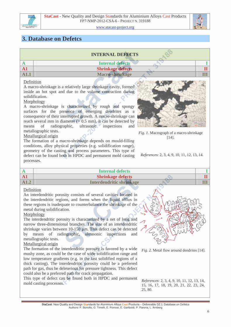
A Internal defects I A1 Shrinkage defects II A1.1 Macro-shrinkage III
A Internal defects I A1 Shrinkage defects II A1.2 Interdendritic shrinkage III
Definition A macro-shrinkage is a relatively large shrinkage cavity, formed inside an hot spot and due to the volume contraction during solidification. Morphology A macro-shrinkage is characterized by rough and spongy surfaces for the presence of emerging dendrites as a consequence of their interrupted growth. A macro-shrinkage can reach several mm in diameter (> 0.5 mm). It can be detected by means of radiographic, ultrasonic inspections and metallographic tests. Metallurgical origin The formation of a macro-shrinkage depends on mould-filling conditions, alloy physical properties (e.g. solidification range), geometry of the casting and process parameters. This type of defect can be found both in HPDC and permanent mold casting processes.
Fig. 1. Macrograph of a macro-shrinkage [14].
Definition An interdendritic porosity consists of several cavities located in the interdendritic regions, and forms when the liquid afflux in these regions is inadequate to counterbalance the shrinkage of the metal during solidification. Morphology The interdendritic porosity is characterized by a net of long and narrow three-dimensional branches. The size of an interdendritic shrinkage varies between 10-150 µm. This defect can be detected by means of radiographic, ultrasonic inspections and metallographic tests. Metallurgical origin The formation of the interdendritic porosity is favored by a wide mushy zone, as could be the case of wide solidification range and low temperature gradients (e.g. in the last solidified regions of a thick casting). The interdendritic porosity could be a preferred path for gas, thus be deleterious for pressure tightness. This defect could also be a preferred path for crack propagation. This type of defect can be found both in HPDC and permanent mold casting processes.
Fig. 2. Metal flow around dendrites [14].
References: 2, 3, 4, 9, 10, 11, 12, 13, 14.
References: 2, 3, 4, 9, 10, 11, 12, 13, 14, 15, 16, 17, 18, 19, 20, 21, 22, 23, 24, 25, 80.

StaCast - New Quality and Design Standards for Aluminium Alloys Cast Products FP7-NMP-2012-CSA-6 - PROJECT N. 319188
www.stacast-project.org
StaCast: New Quality and Design Standards for Aluminium Alloys Cast Products – Deliverable D2.1: Database on Defetcs Authors: F. Bonollo, G. Timelli, E. Fiorese, E. Gariboldi, P. Parona, L. Arnberg
7
A Internal defects I A1 Shrinkage defects II A1.3 Layer porosity III
A Internal defects I A2 Gas-related defects II A2.1 Air entrapment porosity III
Definition A layer porosity consists of a set of shrinkage defects aligned typically along the neutral thermal axis/surface of the casting in its thin regions (where the component thickness is far smaller than the two other dimensions and the thermal gradient is lower than all adjacent points). Morphology A layer porosity is made up of a set of small shrinkage cavities laying on a surface, typically the neutral thermal one. The size of a layer porosity varies between 10-100 µm. This defect can be detected by means of radiographic inspections and metallographic tests. Metallurgical origin The layer porosity forms when the solidification fronts converge towards two surfaces and the last solidifying liquid metal cannot flow within the dendrites of the mushy zone. This type of defect can be found both in HPDC and permanent mold casting processes.
Fig. 3. The formation of a layer porosity.
Definition The air entrapment porosity consists of small cavities due to air bubbles trapped inside the liquid metal. Morphology Air entrapment porosities appear as spherical or ellipsoidal cavities characterized by relatively smooth surfaces on which a thin oxide layer (due to the high-temperature interaction between air and the liquid metal) could be found. The final distribution of cavities within the casting depends on the path of the metal. The size of an air entrapment porosity is 10-2000 µm. This defect can be detected by means of radiographic, ultrasonic inspections and metallographic tests. Metallurgical origin Air entrapment porosity is the most frequent defect found in HPDC products. Air bubbles can form in turbulent liquid metal vein either when it is in the shot sleeve, in filling channels or inside die cavity.
Fig. 4. Entrapped air porosity in the casting [75].
References: 3, 4, 13, 15.
References: 2, 3, 4, 5, 14, 21, 22, 24, 26, 27, 28, 29, 30, 31, 32, 33, 34, 35, 36, 37, 77, 78.

StaCast - New Quality and Design Standards for Aluminium Alloys Cast Products FP7-NMP-2012-CSA-6 - PROJECT N. 319188
www.stacast-project.org
StaCast: New Quality and Design Standards for Aluminium Alloys Cast Products – Deliverable D2.1: Database on Defetcs Authors: F. Bonollo, G. Timelli, E. Fiorese, E. Gariboldi, P. Parona, L. Arnberg
8
A Internal defects I A2 Gas-related defects II A2.2 Hydrogen porosity III
A Internal defects I A2 Gas-related defects II A2.3 Vapour entrapment porosity III
Definition The hydrogen porosity consists of cavities due to the presence of hydrogen in the melt. Morphology Hydrogen porosity consists of approximately spherical cavities characterized by smooth and no-oxidized surface. Such cavities have a rather small size (0.05-0.5 mm of diameter) and are distributed almost homogeneously within the casting. This defect can be detected by means of radiographic, ultrasonic inspections and metallographic tests. Metallurgical origin Humidity can cause the presence of monoatomic hydrogen within the liquid metal at high temperature. Due to the abrupt reduction of hydrogen solubility in the solid phase, the solidifying region rejects hydrogen and this element concentrates in the liquid near the liquid/solid interface, where it combines into molecular form. In HPDC castings, hydrogen porosity is far less frequent than air entrapment porosity. This type of defect can be frequently found in permanent mold casting process.
Fig. 5. Micrograph of a hydrogen porosity [18].
Definition The vapour entrapment porosity consists of cavities caused by the residual humidity of the die. Humidity becomes vapour when it comes into contact with the molten metal. Morphology The vapour entrapment porosity is generally in the form of approximately spherical cavities with smooth surfaces. Due to the generally localized presence of humidity on the die, cavities are typically concentrated, even if in regions of the casting that could be far from the area where they originated. The size of a vapour entrapment porosity is 0.5-3 mm. This defect can be detected by means of radiographic, ultrasonic inspections and metallographic tests. Metallurgical origin The presence of humidity on the die surface could result from an excess of the water-based lubricant. This type of defect can be found both in HPDC and permanent mold casting processes.
Fig. 6. Schematics of vapour entrapment porosity.
References: 3, 4, 14, 15, 18, 37, 38, 39, 40, 41, 42, 76.

StaCast - New Quality and Design Standards for Aluminium Alloys Cast Products FP7-NMP-2012-CSA-6 - PROJECT N. 319188
www.stacast-project.org
StaCast: New Quality and Design Standards for Aluminium Alloys Cast Products – Deliverable D2.1: Database on Defetcs Authors: F. Bonollo, G. Timelli, E. Fiorese, E. Gariboldi, P. Parona, L. Arnberg
9
Definition The lubricant entrapment porosity forms when the gases - resulting from the decomposition of the lubricant - remain trapped into liquid metal in form of bubbles. Morphology The lubricant entrapment porosity is characterized by small, approximately spherical cavities with smooth surfaces. The surface of the cavities appears darker respect to the surface of gas-related defects due to the presence of combustion products on it. The size of a lubricant entrapment porosity varies between 0.5-3 mm. This defect can be detected by means of radiographic, ultrasonic inspections and metallographic tests. Metallurgical origin The lubricant entrapment porosity is caused by an excessive quantity of lubricant on the die surface and/or piston/sleeve coming into contact with molten metal. This type of defect can be found both in HPDC and permanent mold casting processes.
A Internal defects I A2 Gas-related defects II A2.4 Lubricant entrapment porosity III
A Internal defects I A3 Filling-related defects II A3.1 Joint III
Fig. 7. Schematics of lubricant entrapment porosity.
Definition A joint is a discontinuity of metallurgical type (either microstructural and/or metallic) rather than of geometrical-type (such as, for example, a cavity or a crack). Morphology The appearance of this defect depends on the conditions of the metal flows at the moment of their confluence and on their location within the die-cavity. This defect can be detected only by means of metallographic tests. Metallurgical origin The joint forms when a relatively cold liquid metal flow - at least partially solidified and in some cases covered by an oxide film - meets another warmer metal vein that can flow around it. The joint usually brakes along the previous interface of flows when relatively low tension stresses normal to it or shear stresses parallel to it are applied. This type of defect can be found both in HPDC and permanent mold casting processes.
Fig. 8. Micrograph of a joint.
References: 2, 4, 14, 24, 26, 28, 29, 30, 31, 33, 34, 35, 37, 43, 44, 45, 46, 47, 48, 49.
StaCast - New Quality and Design Standards for Aluminium Alloys Cast Products FP7-NMP-2012-CSA-6 - PROJECT N. 319188
www.stacast-project.org
StaCast: New Quality and Design Standards for Aluminium Alloys Cast Products – Deliverable D2.1: Database on Defetcs Authors: F. Bonollo, G. Timelli, E. Fiorese, E. Gariboldi, P. Parona, L. Arnberg
10
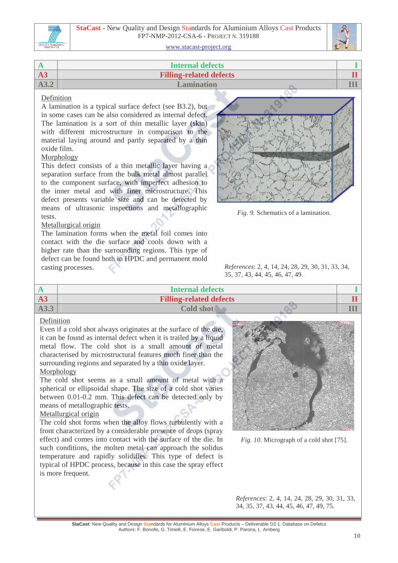
A Internal defects I A3 Filling-related defects II A3.2 Lamination III
A Internal defects I A3 Filling-related defects II A3.3 Cold shot III
Definition A lamination is a typical surface defect (see B3.2), but in some cases can be also considered as internal defect. The lamination is a sort of thin metallic layer (skin) with different microstructure in comparison to the material laying around and partly separated by a thin oxide film. Morphology This defect consists of a thin metallic layer having a separation surface from the bulk metal almost parallel to the component surface, with imperfect adhesion to the inner metal and with finer microstructure. This defect presents variable size and can be detected by means of ultrasonic inspections and metallographic tests. Metallurgical origin The lamination forms when the metal foil comes into contact with the die surface and cools down with a higher rate than the surrounding regions. This type of defect can be found both in HPDC and permanent mold casting processes.
Fig. 9. Schematics of a lamination.
Definition Even if a cold shot always originates at the surface of the die, it can be found as internal defect when it is trailed by a liquid metal flow. The cold shot is a small amount of metal characterised by microstructural features much finer than the surrounding regions and separated by a thin oxide layer. Morphology The cold shot seems as a small amount of metal with a spherical or ellipsoidal shape. The size of a cold shot varies between 0.01-0.2 mm. This defect can be detected only by means of metallographic tests. Metallurgical origin The cold shot forms when the alloy flows turbulently with a front characterized by a considerable presence of drops (spray effect) and comes into contact with the surface of the die. In such conditions, the molten metal can approach the solidus temperature and rapidly solidifies. This type of defect is typical of HPDC process, because in this case the spray effect is more frequent.
Fig. 10. Micrograph of a cold shot [75].
References: 2, 4, 14, 24, 28, 29, 30, 31, 33, 34, 35, 37, 43, 44, 45, 46, 47, 49.
References: 2, 4, 14, 24, 28, 29, 30, 31, 33, 34, 35, 37, 43, 44, 45, 46, 47, 49, 75.

StaCast - New Quality and Design Standards for Aluminium Alloys Cast Products FP7-NMP-2012-CSA-6 - PROJECT N. 319188
www.stacast-project.org
StaCast: New Quality and Design Standards for Aluminium Alloys Cast Products – Deliverable D2.1: Database on Defetcs Authors: F. Bonollo, G. Timelli, E. Fiorese, E. Gariboldi, P. Parona, L. Arnberg
11
A Internal defects I A4 Undesired phases II A4.1 Inclusion III
A Internal defects I A4 Undesired phases II A4.2 Undesired structure III
Definition Inclusions are typically non-metallic phases and include oxides and dross. Morphology The inclusion can be in the form of a particle or of a thin film. The size of an inclusion is major than 0.1 mm. This defect can be detected by means of radiographic, ultrasonic inspections and metallographic tests. Metallurgical origin In Al-alloys the most frequent type of inclusion is the aluminium oxide, i.e. alumina (Al2O3). It easily forms when the liquid metal comes into contact with air. Inclusions can also be other non-metallic phases, such as small portions of refractories (often silicon carbide) or dross. Because of their high hardness, inclusions can cause machining problems. This type of defect can be found both in HPDC and permanent mold casting processes.
Fig. 11. Image of aluminium oxide [75].
Definition These are areas of different microstructure which are undesired mainly for their high hardness, stiffness, brittleness and because they create microstructural discontinuities. Morphology The morphology of undesired structures cannot be uniquely described and their size depends on the cell size. For example, the SDAS could be outside the acceptable limit for a specific region of the casting. This defect can be detected by means of metallographic tests. Metallurgical origin Undesired structures can include portions of previously produced castings (for example flash), accidentally left within the die-cavity and then embedded in the successive casting. Undesired structures represent microstructural discontinuities and could act as crack nucleation and propagation sites during cooling, finishing operations or in-service behaviour. This type of defect can be found both in HPDC and permanent mold casting processes.
Fig. 12. Micrograph of a region with large dendrites [53].
References: 2, 4, 14, 24, 28, 34, 35, 37, 42,43, 44, 45, 46, 47, 50, 51, 52, 52, 76.
References: 2, 4, 52, 53, 54.

StaCast - New Quality and Design Standards for Aluminium Alloys Cast Products FP7-NMP-2012-CSA-6 - PROJECT N. 319188
www.stacast-project.org
StaCast: New Quality and Design Standards for Aluminium Alloys Cast Products – Deliverable D2.1: Database on Defetcs Authors: F. Bonollo, G. Timelli, E. Fiorese, E. Gariboldi, P. Parona, L. Arnberg
12
A Internal defects I A5 Thermal contraction defects II A5.1 Crack III
A Internal defects I A5 Thermal contraction defects II A5.2 Hot tear III
Definition A crack is a geometrical discontinuity characterized by one dimension far smaller than the two others. Morphology A crack is a geometrical discontinuity characterized by one dimension far smaller than the two others. A narrow void volume lays within the two faced fracture surfaces which define crack. The length of a crack varies between 10 µm to several mm. This defect can be detected by means of ultrasonic inspections and metallographic tests. Metallurgical origin In HPDC products, such defect forms at relatively low temperature (far from the solidification range) when the greater thermal contraction of the casting with respect to the die is prevented by the die itself. Cracks can often occur in regions of stress localization, either due to macroscopic geometrical reasons or to the presence of microstructural defects. This type of defect can be found both in HPDC and permanent mold casting processes.
Fig. 13. Schematics of a crack formation.
Definition A hot tear is a brittle crack formed in liquid portions of the mushy zone in the final stages of solidification. Morphology The surface of a hot tear typically displays a dendritic morphology and can be heavily oxidized since formed at high temperature. The length of an hot tear varies between 10 µm to several mm. This defect can be detected by means of metallographic tests. Metallurgical origin The hot tear usually forms in such alloys characterized by a wide solidification temperature range and in hot spot areas at stresses far below the tensile stress at the temperature. The hot tear can also be due of stress concentration for geometrical or microstructural reasons. This type of defect can be found both in HPDC and permanent mold casting processes.
Fig. 14. Micrograph of a hot crack [4].
References: 2, 4.
References: 2, 3, 4, 14, 55, 56, 57.

StaCast - New Quality and Design Standards for Aluminium Alloys Cast Products FP7-NMP-2012-CSA-6 - PROJECT N. 319188
www.stacast-project.org
StaCast: New Quality and Design Standards for Aluminium Alloys Cast Products – Deliverable D2.1: Database on Defetcs Authors: F. Bonollo, G. Timelli, E. Fiorese, E. Gariboldi, P. Parona, L. Arnberg
13
SURFACE DEFECTS
B Surface defects I B1 Shrinkage defects II B1.1 Sink III
B Surface defects I B2 Gas-related defects II B2.1 Blister III
Definition A sink is a surface depression related to the presence of a sub-surface shrinkage porosity. Morphology A sink looks like a surface depression toward the interior of the casting. It extends for several mm. This defect can be detected by means of visual, liquid penetrant inspections and metallographic tests. Metallurgical origin A sink occurs when, during the casting solidification, a hot spot localizes close to the metal/die interface. The skin layer - formed as a consequence of the contact with the die - is not able to sustain stresses arising from the contraction of the sub-surface solidifying region and plastically deforms. The sink is typically found in components with relatively wide plane surfaces or with sharp cross section changes. This type of defect can be found both in HPDC and permanent mold casting processes.
Fig. 15. External surface of a sink [14].
Definition The blister is a porosity defect due to gases entrapment, with the only difference, in comparison with internal defect, that gases are entrapped within a sub-surface region. Morphology A blister is a small amount of material that blown up (with respect to the surrounding surface) in correspondence of a sub-surface gas porosity. A blister extends from 100 µm to several mm. This defect can be detected by means of visual inspections and metallographic tests. Metallurgical origin A blister consists of small surface area that blown up when the internal pressure of sub-surface gas-related porosity is high enough to plastically deform the thin metallic layer that covers it. The metal deformation occurs easily at relatively high temperatures, when castings are ejected from the die or during following heat treatments. This type of defect can be found more frequently in HPDC process, because of turbulent die-filling and consequent air entrapment.
Fig. 16. Example of blisters [74].
References: 2, 14.
References: 2, 14, 58.

StaCast - New Quality and Design Standards for Aluminium Alloys Cast Products FP7-NMP-2012-CSA-6 - PROJECT N. 319188
www.stacast-project.org
StaCast: New Quality and Design Standards for Aluminium Alloys Cast Products – Deliverable D2.1: Database on Defetcs Authors: F. Bonollo, G. Timelli, E. Fiorese, E. Gariboldi, P. Parona, L. Arnberg
14
B Surface defects I B3 Filling-related defects II B3.1 Joint and vortex III
B Surface defects I B3 Filling-related defects II B3.2 Lamination III
Definition The joints are surface wrinkles, slight depressions or simply alterations of castings visual features along the line corresponding to the interface between converging flows. A particular joint defect is the vortex, which forms on the surface when only one flow rolls itself up and generates a particular spiral distribution of oxide films and microstructures. Morphology A joint presents wrinkled surfaces or linear depressions due to the deformation of the cooler and more viscous flow. The surface of the casting can also be unaltered, but the presence of different microstructures of different flows is visible. The vortex has a characteristic spiral-shaped appearance on the surface of the casting. The joint and the vortex can be detected by means of visual inspections and metallographic tests. Metallurgical origin A joint forms when a relatively cold metal flow - at least partially solidified and in some cases covered by an oxide film - meets another warmer metal vein that can flow around it. As explained in the case of the corresponding internal defect (see A3.1), the metallic discontinuity can cause material detachment along it when even relatively low stress arises. This type of defect can be found both in HPDC and permanent mold casting processes.
Fig. 17. Macrograph showing a vortex [74].
Definition A lamination is a thin surface metallic layer having a separation surface from the bulk metal almost parallel to the component surface and with imperfect adhesion to the inner metal. Morphology The lamination seems as a skin with different microstructure and partly separated from the bulk material by an oxide film. This defect can be detected by means of visual inspections and metallographic tests. Metallurgical origin A lamination forms when a relatively warm vein at low viscosity flows between the steel-die and another cooler and partially solidified flow. Laminations could also form as a result of deformations of the die related to sudden pressure changes. The resulting metallic discontinuity can cause the partial or complete skin detachment along the interface, when even relatively low stresses arise or are externally applied. This type of defect can be found both in HPDC and permanent mold casting processes.
Fig. 18. Surface lamination.
References: 2, 3, 4, 14.
References: 2, 4, 14, 24, 28, 29, 30, 31, 33, 34, 35, 37, 43, 44, 45, 46, 47, 49.

StaCast - New Quality and Design Standards for Aluminium Alloys Cast Products FP7-NMP-2012-CSA-6 - PROJECT N. 319188
www.stacast-project.org
StaCast: New Quality and Design Standards for Aluminium Alloys Cast Products – Deliverable D2.1: Database on Defetcs Authors: F. Bonollo, G. Timelli, E. Fiorese, E. Gariboldi, P. Parona, L. Arnberg
15
B Surface defects I B3 Filling-related defects II B3.3 Cold shot III
B Surface defects I B4 Undesired phases II B4.1 Surface deposit III
Definition A cold shot is a small amount of metal characterised by microstructural features much finer than the surrounding regions and separated by a thin oxide layer. Morphology The cold shot looks like a small amount of metal and presents a spherical or ellipsoidal shape. The size of a cold shot varies between 0.01-0.2 mm. This defect can be detected by means of visual inspections and metallographic tests. Metallurgical origin A cold shot forms when a small portion of liquid metal comes into contact with the surface of the die and rapidly solidifies (see A3.3). This condition occurs when the alloy flows turbulently and with a front characterized by a considerable presence of drops (spray effect). This type of defect can be found frequently in HPDC process, because in this case the spray effect is more frequent.
Fig. 19. Macrograph of a surface cold shot [14].
Definition A surface deposit can be a layer of various chemical composition, thickness, distribution and adhesion, which, for various reasons, deposited on the surface of the casting (without chemical interaction) during the process. Morphology A deposit appears as a surface region covered by particles of different chemical composition respect to the casting. A surface deposit usually extends for several mm. This defect can be detected by means of visual inspections and metallographic tests. Metallurgical origin A lubricant excess, which can be transferred from the die to the casting, can cause a surface deposit formation. This type of defect can be found both in HPDC and permanent mold casting processes. Fig. 20. Macrograph of a deposit.
References: 2, 4, 14, 24, 28, 29, 30, 31, 33, 34, 35, 37, 43, 44, 45, 46, 47, 49.

StaCast - New Quality and Design Standards for Aluminium Alloys Cast Products FP7-NMP-2012-CSA-6 - PROJECT N. 319188
www.stacast-project.org
StaCast: New Quality and Design Standards for Aluminium Alloys Cast Products – Deliverable D2.1: Database on Defetcs Authors: F. Bonollo, G. Timelli, E. Fiorese, E. Gariboldi, P. Parona, L. Arnberg
16
B Surface defects I B4 Undesired phases II B4.2 Contaminant or inclusion III
B Surface defects I B5 Thermal contraction defects II B5.1 Crack III
Definition A contaminant can be a layer of various chemical composition, thickness, distribution and adhesion, which, for various reasons, deposited on the surface of the casting during the HPDC process or later, but in some way related to the process. For inclusion definition refer to the corresponding internal defect (A4.1). Morphology When a contaminant defect occurs, the surface of the casting appears locally coloured differently from the other portions (or from the usual color related to the presence of a thin oxide layer). The size of a contaminant or an inclusion is major than 0.1 mm. These defects can be detected by means of visual inspections and metallographic tests. Metallurgical origin Contaminants are the result of interaction between metal and substances locally came into contact with it. Even corrosion of the casting can be included into this type of defect. This defect can be found both in HPDC and permanent mold casting processes.
Fig. 21. Macrograph of a contaminant.
Definition A crack is a defect that can widely extend within the casting, from surface to surface. For this reason, cracks have been included both within internal and surface defects. Refer to the corresponding internal defect (A5.1) for defect definition, causes and morphological features. Morphology A crack is a geometrical discontinuity characterized by one dimension far smaller than the two others. A narrow void volume lays within the two faced fracture surfaces which define crack. The length of a crack extends from 10 µm to several mm. This defect can be detected by means of visual, liquid penetrant, magnetic particle inspections and metallographic tests. Metallurgical origin A crack generally originates on a surface or in a sub-surface position, but it can propagate into internal regions of the casting until reaching the other surface/s. This type of defect can be found both in HPDC and permanent mold casting processes.
Fig. 22. Image of a crack.
References: 2, 4.

StaCast - New Quality and Design Standards for Aluminium Alloys Cast Products FP7-NMP-2012-CSA-6 - PROJECT N. 319188
www.stacast-project.org
StaCast: New Quality and Design Standards for Aluminium Alloys Cast Products – Deliverable D2.1: Database on Defetcs Authors: F. Bonollo, G. Timelli, E. Fiorese, E. Gariboldi, P. Parona, L. Arnberg
17
B Surface defects I B5 Thermal contraction defects II B5.2 Hot tear III
B Surface defects I B6 Metal/die interaction defects II B6.1 Erosion III
Definition A hot tear is a defect that can widely extend within the casting, from surface to surface. For this reason, hot tears have been included both within internal and surface defects. Refer to the corresponding internal defect (A5.2) for defect definition, causes and morphological features. Morphology The surface of a hot tear typically displays a dendritic morphology and can be heavily oxidized since formed at high temperature. The length of a hot tear extends from 10 µm to several mm. This defect can be detected by means of visual, liquid penetrant, magnetic particle inspections and metallographic tests. Metallurgical origin The hot tear usually forms in such alloys characterized by a wide solidification temperature range and in hot spot areas at stresses far below the tensile stress at the temperature. The hot tear can also be due of stress concentration for geometrical or microstructural reasons. This type of defect can be found both in HPDC and permanent mold casting processes.
Fig. 23. Macrograph of a hot crack [57].
Definition Erosion is a defect that reproduces, in negative, a defect of the die caused by erosive phenomena. Morphology Erosion consists of a material excess on the casting caused by the steel removal from the die by erosive wear. The thickness of the erosion defect is 1-200 µm. This defect can be detected by means of visual inspections and metallographic tests. Metallurgical origin The impact of the turbulent flow at high speed and high temperature on the die-cavity can lead to the progressive wear erosion. In addition to the above mentioned factors, erosion is related to the inclination angle of the metal flow with respect to the die surface and to the presence of particles or bubbles inside the liquid metal (cavitation). This type of defect can be found more frequently in HPDC process, due to high pressure and speed of the metal during the die-cavity filling.
Fig. 24. Image of a casting defect caused by die-erosion [75].
References: 2, 3, 4, 14, 55, 56, 57.
References: 2, 14, 55, 59, 60, 61, 75.

StaCast - New Quality and Design Standards for Aluminium Alloys Cast Products FP7-NMP-2012-CSA-6 - PROJECT N. 319188
www.stacast-project.org
StaCast: New Quality and Design Standards for Aluminium Alloys Cast Products – Deliverable D2.1: Database on Defetcs Authors: F. Bonollo, G. Timelli, E. Fiorese, E. Gariboldi, P. Parona, L. Arnberg
18
B Surface defects I B6 Metal/die interaction defects II B6.2 Soldering III
B Surface defects I B6 Metal/die interaction defects II B6.3 Thermal fatigue III
Definition As for other metal/die interaction defects, the metallurgical origin of the die damage (soldering) reflects in the name of the casting defect. Morphology Soldering causes surface roughness or localized lack of material on the casting. The thickness of the soldering defect is 1-200 µm. This defect can be detected by means of visual inspections and metallographic tests. Metallurgical origin The common metallurgical origin of soldering is the formation of intermetallic phases on the die surface and following adhesion of the aluminium alloy on them. Soldering often promptly occurs in regions of the die exposed to liquid metal at relatively high temperature and flow rates. Soldering can also easily take place in the zones of the die where thermal fatigue or erosion phenomena previously occurred. This type of defect can be found more frequently in HPDC process, due to high pressure and speed of the metal during the die-cavity filling.
Fig. 25. Example of soldering effects on the die [14].
Definition Thermal fatigue is the name commonly given to narrow relieves related to corresponding damage of the die. Morphology The defect consists of a set of narrow relieves on the surface of the casting, sometimes referred also as crocodile skin. The thickness of the thermal fatigue defect is 1-200 µm. This defect can be detected by means of visual, liquid penetrant, magnetic particle inspections and metallographic tests. Metallurgical origin As the time of service of the die increases, small cracks can form on its edges or surface, due to the repetition of stress-strain cycles (induced by the rapid heating and cooling stages). The liquid metal filters into cracks and gives rise to the relieves on the surface of the casting. This kind of defect appears on the casting independently from the specific process or relative parameters. This type of defect can be found more frequently in HPDC process, because of the high production rate and consequent severe damage of the die.
Fig. 26. A casting defect caused by the presence of cracks on the die [74].
References: 2, 14, 55, 58, 59, 60, 61, 62, 63, 64, 65, 66, 67, 68, 69, 70, 71.
References: 2, 14, 55, 59, 60, 61, 62, 66, 67, 72, 74, 79.

StaCast - New Quality and Design Standards for Aluminium Alloys Cast Products FP7-NMP-2012-CSA-6 - PROJECT N. 319188
www.stacast-project.org
StaCast: New Quality and Design Standards for Aluminium Alloys Cast Products – Deliverable D2.1: Database on Defetcs Authors: F. Bonollo, G. Timelli, E. Fiorese, E. Gariboldi, P. Parona, L. Arnberg
19
B Surface defects I B6 Metal/die interaction defects II B6.4 Ejection mark III
B Surface defects I B6 Metal/die interaction defects II B6.5 Corrosion of the die III
Definition The ejection mark is a defect related to the presence of an undercut in the die, that could be a result of modifications of the die-geometry (for example due to one of the previously described erosion/soldering phenomena). Morphology The ejection mark appears as a plastic deformation of the casting, that extends along the direction of the ejection from the die. This defect can be detected by means of visual inspections and metallographic tests. Metallurgical origin When the ejection occurs at relatively high temperature, the presence of even a small undercut on the die causes the deformation of the casting around the undercut in the ejection direction. This type of defect can be found more frequently in HPDC process, because of the high production rate and consequent severe damage of the die.
Fig. 27. Image of an ejection mark.
Definition This defect consists of surface roughness of the casting due to damage of the die surface, attacked by the environment (corrosion). Morphology The surface of the product is characterized by high roughness, more evident in correspondence of the severely corroded areas of the die cavity. The thickness of the defect caused by the corrosion of the die is 1-200 µm. This defect can be detected by means of visual inspections and metallographic tests. Metallurgical origin The corrosion of the die is caused by the interaction with the environment and can be homogeneous or localized. An extremely severe corrosion of the die, either homogeneous or localized, can thus lead the casting to be out of tolerance or to have localized excess of material. This type of defect can be found both in HPDC and permanent mold casting processes.
Fig. 28. Image of a casting obtained with a corroded die.

StaCast - New Quality and Design Standards for Aluminium Alloys Cast Products FP7-NMP-2012-CSA-6 - PROJECT N. 319188
www.stacast-project.org
StaCast: New Quality and Design Standards for Aluminium Alloys Cast Products – Deliverable D2.1: Database on Defetcs Authors: F. Bonollo, G. Timelli, E. Fiorese, E. Gariboldi, P. Parona, L. Arnberg
20
GEOMETRY DEFECTS
C Geometry defects I C1 Lack of material II C1.1 Incomplete casting III
C Geometry defects I C2 Excess of material II C2.1 Flash III
Definition An incomplete casting presents a local lack of material with respect to the geometry of the die cavity. Morphology The lack of material can be in order of several mm or cm. This defect can be detected by means of visual inspections. Metallurgical origin Due to an excessively high viscosity, a front portion of the metal flow can stop before the die cavity has been completely filled. This type of defect can be found both in HPDC and permanent mold casting processes.
Fig. 29. Example of incomplete casting [31].
Definition A flash is an excess of material due to metal infiltration inside a thin gap between the die parts. Morphology The flash is a thin layer of material in excess, whose geometry roughly reproduces that of the die separation surface. The excess of material can be in order of several mm or cm. This defect can be detected by means of visual inspections. Metallurgical origin The flash is due to an insufficient clamping force of the machine, which cannot counterbalance the alloy pressure. Flashes are originated also by a different die thermal expansion. This type of defect can be found more frequently in HPDC process, because of the high pressure of the metal.
Fig. 30. Example of flash [74].

StaCast - New Quality and Design Standards for Aluminium Alloys Cast Products FP7-NMP-2012-CSA-6 - PROJECT N. 319188
www.stacast-project.org
StaCast: New Quality and Design Standards for Aluminium Alloys Cast Products – Deliverable D2.1: Database on Defetcs Authors: F. Bonollo, G. Timelli, E. Fiorese, E. Gariboldi, P. Parona, L. Arnberg
21
C Geometry defects I C3 Out of tolerance II C3.1 Deformed part III
Definition A deformed part presents a geometrical non-conformity to its design geometry, even in absence of local excess or lack of material. Morphology The deformation of the casting is major than the established tolerances. This defect can be detected by means of visual inspections. Metallurgical origin The formation of the defect is related to the thermal contraction during cooling, that causes local stress inside the casting. The defect is more pronounced in castings ejected by the die at high temperature and presenting drastic thickness changes. This type of defect can be found both in HPDC and permanent mold casting processes.
Fig. 31. Schematics of out of tolerances castings.

StaCast - New Quality and Design Standards for Aluminium Alloys Cast Products FP7-NMP-2012-CSA-6 - PROJECT N. 319188
www.stacast-project.org
StaCast: New Quality and Design Standards for Aluminium Alloys Cast Products – Deliverable D2.1: Database on Defetcs Authors: F. Bonollo, G. Timelli, E. Fiorese, E. Gariboldi, P. Parona, L. Arnberg
22
4. Dictionary of defects of HPDC and permanent mold casting processes DEFECT
CODE ITALIAN ENGLISH FRANCAIS DEUTSCH ESPAÑOL
A1.1 Macro-porosità Macro-shrinkage Souffloures Makroporosität Macroporosidad
A1.2 Porosità
interdendritica Interdendritic
shrinkage Microretassures Interdendritische Porosität
Porosidad interdendritica
A1.3 Porosità planare Layer porosity Microretassures
centralés des pieces Mittellinienporosität Porosidad planearea
A2.1 Porosità da aria
intrappolata Air entrapment
porosity Porositè d’air
enprisoné Luftporosität
Porosidad de aire atrapado
A2.2 Porosità da idrogeno
Hydrogen porosity Porositè de gaz Dissous dans le
metal Hydrogenporosität
Porosidad de hidrógeno
A2.3 Porosità da umidità
residua
Vapour entrapment
porosity Porositè
Dampfporosität/ /Dampf Feuchtigkeits-
einschluss
Porosidad de humedad restante
A2.4 Porosità da lubrificante
Lubricant entrapment
porosity
Porositè de gaz de poteyage
Porosität durch Verbrennungs-
produkteinschluss
Porosidad de lubricante
A3.1 Giunzione Joint Reprise Verbindung/ kaltflieβstelle
Unión
A3.2 Sfogliatura Lamination Friass Schülpe Foliación A3.3 Goccia fredda Cold shot Goutte froide kalter Tropfen Gota fría A4.1 Inclusione Inclusion Inclusion Einschluβ Inclusión
A4.2 Struttura non
desiderata Undesired structure
Structure ne pas demandée
Nicht gewunschte Struktur Estructura no
deseada A5.1 Cricca Crack Fissure Riβ Grieta A5.2 Cricca a caldo Hot tear Fissure à chaud Warmriβ Grieta en caliente B1.1 Ricalo Sink Retassure Schwindung Hundimiento B2.1 Blister Blister Cloque Blase Burbuja B3.1 Giunzione e vortice Joint and vortex Reprise Kaltstell und Wirbel Unión y remolino B3.2 Sfogliatura Lamination Eclatement Abblätterung/Schülpe Foliación B3.3 Goccia fredda Cold shot Goutte froide kalter Tropfen Gota fría B4.1 Depositi Surface deposits Dépot Schlackenhalde Depósitos
B4.2 Contaminazione o
inclusione Contaminant or inclusion
Trace de lubrifiant, trace de poteyage ou
inclusion
Verunreinigung/ Beschmutzung oder
Einschluss
Contaminación o inclusión
B5.1 Cricca Crack Fissure Riβ Grieta B5.2 Cricca a caldo Hot tear Fissure à chaud Warmriβ Grieta en caliente B6.1 Erosione Erosion Erosion Erosion Erosión B6.2 Metallizzazione Soldering Etamage Metallisierung Metalización
B6.3 Crettature da fatica
termica Thermal fatigue Craquelure Durch thermische Ermüdung
Grieta por fatiga térmica
B6.4 Segno di espulsione Ejection mark Arrachement Auswerfermarke Marca de expulsión
B6.5 Corrosione dello
stampo Corrosion of the
die Corrosion de moule
Druckgussform korrosion/
Korrosion der Druckgussform
Corrosión del molde
C1.1 Getto incompleto Uncomplete
casting Malvenue Unvollstandiges Gussteil Pieza incompleta
C2.1 Bava Flash Bavure Guβgrat Rebaba C3.1 Getto deformato Deformed part Deformation Deformiertes Guβteil Pieza deformada

StaCast - New Quality and Design Standards for Aluminium Alloys Cast Products FP7-NMP-2012-CSA-6 - PROJECT N. 319188
www.stacast-project.org
StaCast: New Quality and Design Standards for Aluminium Alloys Cast Products – Deliverable D2.1: Database on Defetcs Authors: F. Bonollo, G. Timelli, E. Fiorese, E. Gariboldi, P. Parona, L. Arnberg
23
5. References 1) Gruppo di Lavoro Qualità dei Getti Pressocolati: “Qualità dei getti pressocolati: Indagine sulla situazione
attuale, prospettive di una norma sulle condizioni di fornitura dei getti pressocolati”; Centro di Studio Pressocolata, Associazione Italiana di Metallurgia, Milano (2006).
2) D.L. Cocks: “A proposed simple qualitative classification for die-casting defects”; Proc. Die-casting Conference, Montreaux (1996), pp 19/1-19/15.
3) J. Campbell, R.A. Harding: “Casting technology”, in TALAT 2.0 cd-rom, EAA, Brussels, 2000. 4) J. Campbell: “Castings”, Elsevier Science Ltd., Oxford (2003). 5) W.G. Walkington: “Die Casting defects – Causes and solutions”; North American Die Casting Association,
(1997). 6) E. Gariboldi, F. Bonollo, M. Rosso: “Proposal of a classification of defects of high-pressure diecast products”;
La Metallurgia italiana, vol. 99, 6 (2007), p.39. 7) E. Gariboldi, F. Bonollo, M. Rosso: “Classification criteria for defects in diecast components”; Proceedings
High Tech Die Casting 2008, Montichiari (2008). 8) F. Bonollo, S. Odorizzi: “Numerical Simulation of Foundry Processes”; SGE, Padova (2001). 9) M.C. Flemings: “Solidification Processing”; Mc Graw Hill, New York (1974). 10) ASM Metals Handbook, 10th ed., vol. 15, “Casting”; ASM - Metals Park, Ohio (1990). 11) E. Di Russo, “Atlante Metallografico delle leghe di alluminio da fonderia”; Edimet, Brescia (1991). 12) J.R. Brown, “Non-ferrous foundryman’s handbook”; Butterworth, Oxford (1999). 13) K. Kubo, R.D. Pehlke, “Mathematical modeling of porosity formation in solidification”; Metallurgical
Transactions, 16B (1985), pp 359-366. 14) G. Timelli, F. Bonollo: “Microstructure, defects and properties in aluminium alloys castings: a review”; Proc.
Int. Conf. Aluminium Two Thousand, Firenze (2007). 15) P.D. Lee, A. Chirazi, D. See: “Modeling microporosity in aluminum-silicon alloys: a review”; Journal of
Light Metals 1 (2001) 15-30 16) Y.W. Lee, E. Chang, C.F. Chieu: “Modeling of feeding behavior of solidifying Al-7Si-0.3Mg alloy plate
casting”; Metallurgical Transactions, 21B (1990), pp 715-722. 17) R. H. Mathiesen, L. Arnberg, K. Ramsoskar: “Time Resolved X-Ray Imaging of Aluminium Alloy
Solidification Process”; Metall. Mat. Trans, 33B (2002) 613-623. 18) J. P. Anson, J. E. Gruzleski: “The Quantitative Discrimination between Shrinkage and Gas Microporosity in
Cast Aluminum Alloys Using Spatial Data Analysis”; Mat. Char., 43 (1999), 319-335. 19) T.S.Shin, L.W.Huang, Y.Chen: “Relative porosity in aluminium and aluminium alloys”; Int. J. Cast Metals
Res., 18 (2005), pp 301-308. 20) L.H.Shang, F.Paray, J.E Gruzleski, S.Bergeron, C.Mercadante, C.A.Loong: “Prediction of microporosity in
Al-Si castings in low pressure permanent mould casting using criteria functions”, Int. J. Cast Metals Res., 17 (2004), pp 193-200.
21) Q.G. Wang, D. Apelian, D.A. Lados: “Fatigue behaviour of A356-T6 aluminum cast alloys. Part I. Effect of casting defects”, J. Light Met., 1 (2001), 73-84.
22) Q.G. Wang, D. Apelian, D.A. Lados: “Fatigue behaviour of A356/357 aluminum cast alloys. Part II - Effect of microstructural constituents”; J. Light Met., 1 (2001), 85-97.
23) J.A. Francis, G.M.D. Cantin: “The role of defects in the fracture of an Al-Si-Mg cast alloy”; Mater. Sci. Eng. A, 407 (2005), 322-329.
24) S. Akhtar, L. Arnberg, M. Di Sabatino, G. Timelli, F. Bonollo: “A Comparative study of defects and mechanical properties in high pressure die cast and gravity die cast Aluminium alloys”; International Foundry Research, 2 (2009), 36-48.
25) M. Merlin, G. Timelli, F. Bonollo, G.L. Garagnani: “Impact behaviour of A356 alloy for low-pressure die casting automotive wheels”; Journal of Materials Processing Technologies, 209, 2 (2009); pp 1060-1073.
26) X. Dai, X. Yang, J. Campbell, J. Wood: “Effects of runner system design on the mechanical strength of Al-7Si-Mg alloy castings”; Mater. Sci. Eng. A, 354 (2003), 315-325.
27) C.H. Cáceres, B.I. Selling, “Casting defects and the tensile properties of an Al-Si-Mg alloy”; Mater. Sci. Eng. A, 220 (1996), 109-116.
28) M. Avalle, G. Belingardi, M.P. Cavatorta, R. Doglione: “Casting defects and fatigue strength of a die cast aluminium alloy: A comparison between standard specimens and production components”; Int. J. Fatigue, 24 (2002), 1-9.
29) C.H. Cáceres: “A phenomenological approach to the quality index of Al-Si-Mg casting alloys”; Int. J. Cast Metals Res., 12 (2000), 367-375.

StaCast - New Quality and Design Standards for Aluminium Alloys Cast Products FP7-NMP-2012-CSA-6 - PROJECT N. 319188
www.stacast-project.org
StaCast: New Quality and Design Standards for Aluminium Alloys Cast Products – Deliverable D2.1: Database on Defetcs Authors: F. Bonollo, G. Timelli, E. Fiorese, E. Gariboldi, P. Parona, L. Arnberg
24
30) C.H. Cáceres: “A rationale for the quality index of Al-Si-Mg casting alloys”; Int. J. Cast Metals Res., 12 (2000), 385-391.
31) G. O. Verran, R.P.K. Mendes, M.A. Rossi: “Influence of injection parameters on defects formation in die casting Al12Si1,3Cu alloy: Experimental results and numeric simulation”; Journal of Materials Processing Technology, 179 (2006) 190–195.
32) J. Campbell: “Materials perspective, Entrainment defects”; Materials science and technology, (2006), Vol 22, No 2, pp 132-136.
33) F. Faura, J. López, J. Hernández: “On the optimum plunger acceleration law in the slow shot phase of pressure die casting machines”; Int. J. Mach. Tools Manuf., 41 (2001), 173-191.
34) G. Timelli, F. Bonollo: “Quality mapping of Aluminium alloy diecastings”; Metallurgical Science and Technology, 26-1 (2008), pp 2-8.
35) G. Timelli, F. Bonollo, G. Cupitò: “The impact of defects on the quality of Aluminium alloys diecastings”; ATA – Ingegneria dell’autoveicolo, 62 (1/2) (2009), pp 12-19.
36) J.Z. Yi: “Statistical modeling of microstructure and defect population effects on the fatigue performance of cast A356-T6 automotive components”; Mat. Sci. Eng., A432 (2006), 59-68.
37) Q.G. Wang: “Oxide Films, Pores and the Fatigue Lives of Cast Aluminum Alloys”; Metall. And Mater. Trans. 37B (2006) 887–895.
38) A.W Moores, A. Froesher: “New device for the determination of hydrogen concentration in aluminum alloy”, AFS Transactions, (2005), pp 1-10.
39) P. Marcolongo, J. W. Evans, D. A. Steingart, F. Bonollo: “Nuova sonda per rilevare le bolle di gas – Parte 1”; Pressocolata e Tecniche Fusorie, 2 (2007), pp 117-121.
40) P. Marcolongo, J. W. Evans, D. A. Steingart, F. Bonollo: “Nuova sonda per rilevare le bolle di gas – Parte 2”; Pressocolata e Tecniche Fusorie, 2 (2007), pp 96-101.
41) R.C. Atwood: “Diffusion controlled growth of Hydrogen pores in Al-Si castings: in situ observation and modeling”; Acta mater. 48 (2000), 405-417.
42) X.G.Chen, J.E Gruzleski: “Influence of melt cleanliness on pore formation in aluminium-silicon alloys”; Int. J. Cast Metals Res., 9(1996), pp 17-26.
43) X.Yang, X.Huang, X.Dai, J.Campbell, J.Tatler: “Numerical modelling of entrainment of oxide film defects in filling of aluminium alloy castings”; Int. J. Cast Metals Res., 17 (2004), pp 321-331.
44) X. Dai, X. Yang, J. Campbell, J. Wood: “Influence of oxide film defects generated in filling on mechanical strength of aluminium alloy castings”; Mater. Sci. Technol., 20 (2004), 505-513.
45) S. Fox, J. Campbell: “Visualisation of oxide film defects during solidification of aluminium alloys”; Scripta Mater., 43 (2000), 881-886.
46) D. Dispinar, J. Campbell: “Use of bifilm index as an assessment of liquid metal quality”; Int. J. Cast Metals Res., 19 (2006), pp 5-17.
47) J. Campbell: “An overview of the effects of Bifilms on the structure and properties of cast alloys”; Metall. and Mater. Trans. 37B (2006) 857–863.
48) J. Espinoza-Cuadra, G. Garcıa-Garcıa, H. Mancha-Molinar: “Influence of defects on strength of industrial aluminum alloy Al–Si 319”, Materials & Design, 28, 3 (2007), 1038-1044.
49) A.K.M. Aziz Ahamed, H. Kato, K. Kageyama, T. Komazaki: “Acoustic visualization of cold flakes and crack propagation in aluminum alloy die-cast plate”; Mater. Sci. Eng. A423, 313-323 (2006).
50) F-Liu, F.H. Samuel: “Effect of inclusions on the tensile properties of Al-7%Si-0.35% Mg (A356.2) aluminium casting alloy”; J. Mat. Sci., 33 (1998), 2269-2281.
51) M. Seniw, J. Conley, M. Fine: “The effect of microscopic inclusion locations and silicon segregation on fatigue lifetimes of aluminum alloy A356 castings”, Mat. Sci. Eng., A285 (2000) 43–48.
52) L. Wang, M. Makhlouf, D. Apelian: “Aluminum Die-Casting Alloys - Alloy Composition, Microstructure, and Properties/Performance Relationship”, International Materials Review, 40 (1995), pp 221-238.
53) G. Timelli, O. Lohne, L. Arnberg, H.I. Laukli: “Effect of solution heat treatments on the microstructure and mechanical properties of a diecast Al-Si7-Mg-Mn alloy”; Metallurgical and Materials Transactions, 39A (2008), pp 1747-1758.
54) T.P. Battle: “Mathematical modelling of solute segregation in solidifying materials”, International Materials Review, 37 (1992), pp 239-270.
55) J. Farupi, J.M. Drezet, M. Rappaz: “In situ observation of hot tearing formation in succilonitrile-acetone”; Acta mater. 49 (2001), 1261–1269.
56) X. Yan, J.C. Lin: “Prediction of Hot Tearing tendency for multicomponent Aluminum alloys”; Metall. And Mater. Trans. 37B (2006) 913–918.
57) A. Knuutinen, K. Nogita, S.D. McDonald, A.K. Dahle: “Porosity formation in aluminium alloy A356 modified with Ba, Ca, Y and Yb”; Journal of Light Metals, 1 (2001), 241–249

StaCast - New Quality and Design Standards for Aluminium Alloys Cast Products FP7-NMP-2012-CSA-6 - PROJECT N. 319188
www.stacast-project.org
StaCast: New Quality and Design Standards for Aluminium Alloys Cast Products – Deliverable D2.1: Database on Defetcs Authors: F. Bonollo, G. Timelli, E. Fiorese, E. Gariboldi, P. Parona, L. Arnberg
25
58) X.P. Niu, B.H. Hua, I. Pinwilla, H. Lib: “Vacuum assisted high pressure die casting of aluminium alloys”; Journal of Materials Processing Technology, 105 (2000) 119-127.
59) B. Kosec, L. Kosec, J. Kopac: “Analysis of casting die failures”; Engineering Failure Analysis, 8 (2001), 355-359.
60) Z. W. Chen, M. Z. Jahedi: “Die erosion and its effect on soldering formation in high pressure die casting of aluminium alloys”; Materials & Design, 20, 6 (1999), 303-309.
61) C. Mitterer, F. Holler, F. Üstel, D. Heim: “Application of hard coatings in aluminium die casting — soldering, erosion and thermal fatigue behaviour”; Surface and Coatings Technology, 125, 1-3 (2000), 233-239.
62) S. Gulizia, M.Z. Jahedi, E.D. Doyle: “Performance evaluation of PVD coatings for high pressure die casting”; Surface and Coatings Technology, 140 (2001), 200-205.
63) K. Domkin, J.H. Hattel, J. Thorborg: “Modeling of high temperature- and diffusion-controlled die soldering in aluminum high pressure die casting”; Journal of Materials Processing Technology, 209, 8 (2009), 4051-4061.
64) H. Zhu, J. Guo, J. Ji: “Experimental study and theoretical analysis on die soldering in aluminum die casting”; Journal of Materials Processing Technology, 123, 2 (2002), 229-235.
65) V. Joshi, A. Srivastava, R. Shivpuri: “Intermetallic formation and its relation to interface mass loss and tribology in die casting dies”; Wear, 256, 11-12 (2004), 1232-1235.
66) E.K. Tentardini, A.O. Kunrath, C. Aguzzoli, M. Castro, J.J. Moore, I.J.R. Baumvol: “Soldering mechanisms in materials and coatings for aluminum die casting”; Surface and Coatings Technology, 202, 16 (2008), 3764-3771.
67) Y. Zhu, D. Schwam, J.F. Wallace, S. Birceanu: “Evaluation of soldering, washout and thermal fatigue resistance of advanced metal materials for aluminum die-casting dies”; Materials Science and Engineering, A379, 1-2 (2004), 420-431
68) S. Shankar, D. Apelian: “Die Soldering: Mechanism of the Interface Reaction between Molten Aluminum Alloy and Tool Steel”; Metallurgical and Materials Transactions, 33B (2002), 465-476.
69) M. Sundqvist, S. Hogmark: “The mechanisms of erosive wear of die casting dies for aluminium”; Proceedings of the Int. European Conf. on Tooling Materials (1992), pp. 453-466.
70) E. Bernacchi, A. Ferrero, G. Gariboldi, A. Korovkin, G. Pontini: “PVD coatings in aluminium die casting dies and steel forming tools”; Metallurgical Science and Technology, 14, 1 (1996), pp. 3-11.
71) M. Bucci: “Analisi della difettologia su pressofusi in lega AlSi12Cu2Fe lavorati meccanicamente”; tesi di laurea, Università di Padova (1998).
72) A. Persson, S. Hogmark, J. Bergstrom: “Failure modes in field-tested die casting dies”; J. Material Processing Technology, 148 (2004), pp 108-118.
73) “20 Difetti 20” – Report interno SIMI, redatto in collaborazione tra l’ente tecnico e la qualità (2005) 74) L. Kallien, “Pressure die casting, conventional and innovative”, 12th International Summer School, Vicenza,
25-29 July 2011 75) A. Manente, ASSOFOND congress, 26-27 october 2012 76) G. Eisaabadi B., P. Davami, S.K. Kim, N. Varahram, “Effects of hydrogen and oxides on tensile properties of
Al-Si-Mg cast alloys”, Materials Science and Engineering A 552 (2012) 36-47 77) G. Timelli, “Constitutive and stochastic models to predict the effect of casting defects on the mechanical
properties of High Pressure Die Cast AlSi9Cu3(Fe) alloys”, Metallurgical Science and Technology 28 n. 2 (2010) 9-17
78) C. D. Lee, “Variability in the impact properties of A356 aluminum alloy on micro-porosity variation”, Materials Science & Engineering A 565 (2013) 187-195
79) A. Long, D. Thornhill, C. Armstrong, D. Watson, “Predicting die life from die temperature for high pressure die casting aluminium alloy”, Applied Thermal Engineering 44 (2012) 100-107
80) G. Nicoletto, R. Konecˇná, S. Fintova, “Characterization of micro-shrinkage casting defects of Al-Si alloys by X-ray computed tomography and metallography”, International Journal of Fatigue 41 (2012) 39-46.


![SESAR 2020 - 763601 - D2.1 - Scenarios and Requirements · SESAR 2020 - 763601 - D2.1 - Scenarios and Requirements DeliverableID [D2.1] ProjectAcronym DroC2om Grant: 763601 Call:](https://img.pdfslide.net/doc/110x75/603a54b6ac67ff69d9242d39/sesar-2020-763601-d21-scenarios-and-requirements-sesar-2020-763601-d21.jpg)