Embed Size (px)
Citation preview
D0–DCM Data
Communications
Module
Manual Number D0–DCM–M
WARNING
Thank you for purchasing automation equipment from Automationdirect.com™, doing business as,AutomationDirect. We want your new DirectLOGIC™ automation equipment to operate safely. Anyone who installsor uses this equipment should read this publication (and any other relevant publications) before installing or operatingthe equipment.
To minimize the risk of potential safety problems, you should follow all applicable local and national codes that regulatethe installation and operation of your equipment. These codes vary from area to area and usually change with time. It isyour responsibility to determine which codes should be followed, and to verify that the equipment, installation, andoperation are in compliance with the latest revision of these codes.
At a minimum, you should follow all applicable sections of the National Fire Code, National Electrical Code, and thecodes of the National Electrical Manufacturer’s Association (NEMA). There may be local regulatory or governmentoffices that can also help determine which codes and standards are necessary for safe installation and operation.
Equipment damage or serious injury to personnel can result from the failure to follow all applicable codes andstandards. We do not guarantee the products described in this publication are suitable for your particular application,nor do we assume any responsibility for your product design, installation, or operation.
Our products are not fault–tolerant and are not designed, manufactured or intended for use or resale as on–line controlequipment in hazardous environments requiring fail–safe performance, such as in the operation of nuclear facilities,aircraft navigation or communication systems, air traffic control, direct life support machines, or weapons systems, inwhich the failure of the product could lead directly to death, personal injury, or severe physical or environmentaldamage (”High Risk Activities”). AutomationDirect specifically disclaims any expressed or implied warranty of fitnessfor High Risk Activities.
For additional warranty and safety information, see the Terms and Conditions section of our Desk Reference. If youhave any questions concerning the installation or operation of this equipment, or if you need additional information,please call us at 770–844–4200.
This publication is based on information that was available at the time it was printed. At AutomationDirect weconstantly strive to improve our products and services, so we reserve the right to make changes to the products and/orpublications at any time without notice and without any obligation. This publication may also discuss features that maynot be available in certain revisions of the product.
TrademarksThis publication may contain references to products produced and/or offered by other companies. The product andcompany names may be trademarked and are the sole property of their respective owners. AutomationDirectdisclaims any proprietary interest in the marks and names of others.
Copyright 2007, Automationdirect.com™ IncorporatedAll Rights Reserved
No part of this manual shall be copied, reproduced, or transmitted in any way without the prior, written consent ofAutomationdirect.com™ Incorporated. AutomationDirect retains the exclusive rights to all information included inthis document.
AVERTISSEMENT
Nous vous remercions d’avoir acheté l’équipement d’automatisation de Automationdirect.com�, en faisant des affairescomme, AutomationDirect. Nous tenons à ce que votre nouvel équipement d’automatisation DirectLOGIC™ fonctionneen toute sécurité. Toute personne qui installe ou utilise cet équipement doit lire la présente publication (et toutes les autrespublications pertinentes) avant de l’installer ou de l’utiliser.
Afin de réduire au minimum le risque d’éventuels problèmes de sécurité, vous devez respecter tous les codes locaux etnationaux applicables régissant l’installation et le fonctionnement de votre équipement. Ces codes diffèrent d’une région àl’autre et, habituellement, évoluent au fil du temps. Il vous incombe de déterminer les codes à respecter et de vous assurerque l’équipement, l’installation et le fonctionnement sont conformes aux exigences de la version la plus récente de cescodes.
Vous devez, à tout le moins, respecter toutes les sections applicables du Code national de prévention des incendies, duCode national de l’électricité et des codes de la National Electrical Manufacturer’s Association (NEMA). Des organismes deréglementation ou des services gouvernementaux locaux peuvent également vous aider à déterminer les codes ainsi queles normes à respecter pour assurer une installation et un fonctionnement sûrs.
L’omission de respecter la totalité des codes et des normes applicables peut entraîner des dommages à l’équipement oucauser de graves blessures au personnel. Nous ne garantissons pas que les produits décrits dans cette publicationconviennent à votre application particulière et nous n’assumons aucune responsabilité à l’égard de la conception, del’installation ou du fonctionnement de votre produit.
Nos produits ne sont pas insensibles aux défaillances et ne sont ni conçus ni fabriqués pour l’utilisation ou la revente en tantqu’équipement de commande en ligne dans des environnements dangereux nécessitant une sécurité absolue, parexemple, l’exploitation d’installations nucléaires, les systèmes de navigation aérienne ou de communication, le contrôle dela circulation aérienne, les équipements de survie ou les systèmes d’armes, pour lesquels la défaillance du produit peutprovoquer la mort, des blessures corporelles ou de graves dommages matériels ou environnementaux (”activités à risqueélevé”). La société AutomationDirect nie toute garantie expresse ou implicite d’aptitude à l’emploi en ce qui a trait auxactivités à risque élevé.
Pour des renseignements additionnels touchant la garantie et la sécurité, veuillez consulter la section Modalités etconditions de notre documentation. Si vous avez des questions au sujet de l’installation ou du fonctionnement de cetéquipement, ou encore si vous avez besoin de renseignements supplémentaires, n’hésitez pas à nous téléphoner au770–844–4200.
Cette publication s’appuie sur l’information qui était disponible au moment de l’impression. À la société AutomationDirect,nous nous efforçons constamment d’améliorer nos produits et services. C’est pourquoi nous nous réservons le droitd’apporter des modifications aux produits ou aux publications en tout temps, sans préavis ni quelque obligation que ce soit.La présente publication peut aussi porter sur des caractéristiques susceptibles de ne pas être offertes dans certainesversions révisées du produit.
Marques de commerceLa présente publication peut contenir des références à des produits fabriqués ou offerts par d’autres entreprises. Lesdésignations des produits et des entreprises peuvent être des marques de commerce et appartiennent exclusivement àleurs propriétaires respectifs. AutomationDirect� nie tout intérêt dans les autres marques et désignations.
Copyright 2007, Automationdirect.com� IncorporatedTous droits réservés
Nulle partie de ce manuel ne doit être copiée, reproduite ou transmise de quelque façon que ce soit sans le consentementpréalable écrit de la société Automationdirect.com� Incorporated. AutomationDirect conserve les droits exclusifs àl’égard de tous les renseignements contenus dans le présent document.
�
Manual RevisionsIf you contact us in reference to this manual, please remember to include the revision number.
Title: DL05/06 Data Communications ModuleManual Number: D0–DCM–M
Issue Date Description of Changes
Original 08/05 Original Issue
2nd Edition 09/07 DirectSOFT5 updates
�
Table of ContentsChapter 1: IntroductionManual Overview 1–2. . . . . . . . . . . . . . . . . . . . . . . . . . . . . . . . . . . . . . . . . . . . . . . . . . . . . . . . . . . . . . . . . . . . .
The Purpose of this Manual 1–2. . . . . . . . . . . . . . . . . . . . . . . . . . . . . . . . . . . . . . . . . . . . . . . . . . . . . . . . . Supplemental Manuals 1–2. . . . . . . . . . . . . . . . . . . . . . . . . . . . . . . . . . . . . . . . . . . . . . . . . . . . . . . . . . . . . . Technical Support 1–2. . . . . . . . . . . . . . . . . . . . . . . . . . . . . . . . . . . . . . . . . . . . . . . . . . . . . . . . . . . . . . . . . . Conventions Used 1–3. . . . . . . . . . . . . . . . . . . . . . . . . . . . . . . . . . . . . . . . . . . . . . . . . . . . . . . . . . . . . . . . . . Key Topics for Each Chapter 1–3. . . . . . . . . . . . . . . . . . . . . . . . . . . . . . . . . . . . . . . . . . . . . . . . . . . . . . . . .
D0–DCM Overview 1–4. . . . . . . . . . . . . . . . . . . . . . . . . . . . . . . . . . . . . . . . . . . . . . . . . . . . . . . . . . . . . . . . . . . Important Configuration Information and PLC Firmware Requirements 1–4. . . . . . . . . . . . . . . . . . . . Hardware Features 1–4. . . . . . . . . . . . . . . . . . . . . . . . . . . . . . . . . . . . . . . . . . . . . . . . . . . . . . . . . . . . . . . . . Module Uses 1–4. . . . . . . . . . . . . . . . . . . . . . . . . . . . . . . . . . . . . . . . . . . . . . . . . . . . . . . . . . . . . . . . . . . . . .
DCM Application Examples 1–5. . . . . . . . . . . . . . . . . . . . . . . . . . . . . . . . . . . . . . . . . . . . . . . . . . . . . . . . . . . DirectNET Master or Slave 1–5. . . . . . . . . . . . . . . . . . . . . . . . . . . . . . . . . . . . . . . . . . . . . . . . . . . . . . . . . . Additional Communications Port 1–6. . . . . . . . . . . . . . . . . . . . . . . . . . . . . . . . . . . . . . . . . . . . . . . . . . . . . Modbus RTU Master or Slave 1–6. . . . . . . . . . . . . . . . . . . . . . . . . . . . . . . . . . . . . . . . . . . . . . . . . . . . . . . .
Chapter 2: Installation, Network Cabling and ModuleSpecificationsInserting the D0–DCM into the PLC 2–2. . . . . . . . . . . . . . . . . . . . . . . . . . . . . . . . . . . . . . . . . . . . . . . . . . . .
D0–DCM Module Installation 2–2. . . . . . . . . . . . . . . . . . . . . . . . . . . . . . . . . . . . . . . . . . . . . . . . . . . . . . . . PLC Firmware and DirectSOFT Requirements 2–2. . . . . . . . . . . . . . . . . . . . . . . . . . . . . . . . . . . . . . . . .
Building the Communication Cable 2–3. . . . . . . . . . . . . . . . . . . . . . . . . . . . . . . . . . . . . . . . . . . . . . . . . . . . Consideration 1: Physical Configuration 2–3. . . . . . . . . . . . . . . . . . . . . . . . . . . . . . . . . . . . . . . . . . . . . . . Consideration 2: Electrical Specification RS232 or RS422/485 2–4. . . . . . . . . . . . . . . . . . . . . . . . . . . Consideration 3: Cable Schematics 2–4. . . . . . . . . . . . . . . . . . . . . . . . . . . . . . . . . . . . . . . . . . . . . . . . . . . Consideration 4: Cable Specifications 2–5. . . . . . . . . . . . . . . . . . . . . . . . . . . . . . . . . . . . . . . . . . . . . . . . . Consideration 5: Installation Guidelines 2–5. . . . . . . . . . . . . . . . . . . . . . . . . . . . . . . . . . . . . . . . . . . . . . .
Wiring Diagrams 2–6. . . . . . . . . . . . . . . . . . . . . . . . . . . . . . . . . . . . . . . . . . . . . . . . . . . . . . . . . . . . . . . . . . . . . D0–DCM Port 1 RS–232 Network 2–6. . . . . . . . . . . . . . . . . . . . . . . . . . . . . . . . . . . . . . . . . . . . . . . . . . . . D0–DCM Port 2 RS–485 Network 2–6. . . . . . . . . . . . . . . . . . . . . . . . . . . . . . . . . . . . . . . . . . . . . . . . . . . . D0–DCM Port 2 RS–422 Network 2–7. . . . . . . . . . . . . . . . . . . . . . . . . . . . . . . . . . . . . . . . . . . . . . . . . . . .
Module Specifications 2–8. . . . . . . . . . . . . . . . . . . . . . . . . . . . . . . . . . . . . . . . . . . . . . . . . . . . . . . . . . . . . . . . General Specifications 2–8. . . . . . . . . . . . . . . . . . . . . . . . . . . . . . . . . . . . . . . . . . . . . . . . . . . . . . . . . . . . . . Port 1 Specifications 2–8. . . . . . . . . . . . . . . . . . . . . . . . . . . . . . . . . . . . . . . . . . . . . . . . . . . . . . . . . . . . . . . . Port 2 Specifications 2–9. . . . . . . . . . . . . . . . . . . . . . . . . . . . . . . . . . . . . . . . . . . . . . . . . . . . . . . . . . . . . . . . Status Indicators 2–9. . . . . . . . . . . . . . . . . . . . . . . . . . . . . . . . . . . . . . . . . . . . . . . . . . . . . . . . . . . . . . . . . . .
Chapter 3: D0–DCM Module SetupImportant Module Configuration Information 3–2. . . . . . . . . . . . . . . . . . . . . . . . . . . . . . . . . . . . . . . Tip for DirectSOFT5 Users (optional) 3–2. . . . . . . . . . . . . . . . . . . . . . . . . . . . . . . . . . . . . . . . . . . . . . Using DirectSOFT5 to Configure the DCM 3–3. . . . . . . . . . . . . . . . . . . . . . . . . . . . . . . . . . . . . . . . . .
DirectSOFT5 PLC>Menu>Setup 3–3. . . . . . . . . . . . . . . . . . . . . . . . . . . . . . . . . . . . . . . . . . . . . . . . . Select DCM Slot 3–3. . . . . . . . . . . . . . . . . . . . . . . . . . . . . . . . . . . . . . . . . . . . . . . . . . . . . . . . . . . . . . . Port 1 Configuration (slave only) 3–4. . . . . . . . . . . . . . . . . . . . . . . . . . . . . . . . . . . . . . . . . . . . . . . . . Port 2 Configuration (slave mode) 3–5. . . . . . . . . . . . . . . . . . . . . . . . . . . . . . . . . . . . . . . . . . . . . . . .
iiTable of Contents
Port 2 Configuration (DirectNET Master) 3–6. . . . . . . . . . . . . . . . . . . . . . . . . . . . . . . . . . . . . . . . . . Port 2 Configuration (Modbus Master) 3–7. . . . . . . . . . . . . . . . . . . . . . . . . . . . . . . . . . . . . . . . . . . . Port 2 Configuration (Non–Sequence) 3–8. . . . . . . . . . . . . . . . . . . . . . . . . . . . . . . . . . . . . . . . . . . .
D0–DCM Port Configuration Registers 3–9. . . . . . . . . . . . . . . . . . . . . . . . . . . . . . . . . . . . . . . . . . . . . Module Configuration Registers 3–9. . . . . . . . . . . . . . . . . . . . . . . . . . . . . . . . . . . . . . . . . . . . . . . . . . Default Communications Parameters 3–9. . . . . . . . . . . . . . . . . . . . . . . . . . . . . . . . . . . . . . . . . . . . . Parameter Descriptions 3–10. . . . . . . . . . . . . . . . . . . . . . . . . . . . . . . . . . . . . . . . . . . . . . . . . . . . . . . . A: Port 1 – Transmit Mode, Protocol 3–11. . . . . . . . . . . . . . . . . . . . . . . . . . . . . . . . . . . . . . . . . . . . . B: Port 1 – Station Address, Baud Rate, Parity 3–12. . . . . . . . . . . . . . . . . . . . . . . . . . . . . . . . . . . . C: Port 2 – RTS On/Off delay, Transmit Mode, Protocol, Comm Time–out, RS–485 Mode 3–13D: Port 2 – Station Address, Baud Rate, Data Bit, Stop Bit, Parity 3–15. . . . . . . . . . . . . . . . . . . E: Port 2 – Character Time–out 3–16. . . . . . . . . . . . . . . . . . . . . . . . . . . . . . . . . . . . . . . . . . . . . . . . . F: Port 1 and 2 Setup and Completion Code 3–17. . . . . . . . . . . . . . . . . . . . . . . . . . . . . . . . . . . . . . G: Port 1 and 2 Reset Time–out 3–17. . . . . . . . . . . . . . . . . . . . . . . . . . . . . . . . . . . . . . . . . . . . . . . . .
Using Ladder Logic to Setup the D0–DCM (DL05) 3–18. . . . . . . . . . . . . . . . . . . . . . . . . . . . . . . . . . Port 1 Example: (This port is a slave only) 3–18. . . . . . . . . . . . . . . . . . . . . . . . . . . . . . . . . . . . . . . . Port 2 Example: Slave Mode 3–18. . . . . . . . . . . . . . . . . . . . . . . . . . . . . . . . . . . . . . . . . . . . . . . . . . . . Port 2 Example: DirectNet Master 3–19. . . . . . . . . . . . . . . . . . . . . . . . . . . . . . . . . . . . . . . . . . . . . . . Port 2 Example: MODBUS RTU Master 3–19. . . . . . . . . . . . . . . . . . . . . . . . . . . . . . . . . . . . . . . . . .
Using ladder Logic to Setup the D0–DCM (DL06) 3–20. . . . . . . . . . . . . . . . . . . . . . . . . . . . . . . . . . Port 1 Example: Slave Mode Only 3–20. . . . . . . . . . . . . . . . . . . . . . . . . . . . . . . . . . . . . . . . . . . . . . . Port 2 Example: Slave Mode 3–20. . . . . . . . . . . . . . . . . . . . . . . . . . . . . . . . . . . . . . . . . . . . . . . . . . . . Port 2 Example: DirectNet Master 3–21. . . . . . . . . . . . . . . . . . . . . . . . . . . . . . . . . . . . . . . . . . . . . . . Port 2 Example: MODBUS RTU Master 3–21. . . . . . . . . . . . . . . . . . . . . . . . . . . . . . . . . . . . . . . . . .
Chapter 4: DirectNet Communications Using RX/WXRX / WX Network Instructions 4–2. . . . . . . . . . . . . . . . . . . . . . . . . . . . . . . . . . . . . . . . . . . . . . . . . . . . . . . . .
Read (RX) and Write (WX) Instructions 4–2. . . . . . . . . . . . . . . . . . . . . . . . . . . . . . . . . . . . . . . . . . . . . . . Building the Read (RX) or Write (WX) Routine 4–2. . . . . . . . . . . . . . . . . . . . . . . . . . . . . . . . . . . . . . . . . The First LD Instruction 4–2. . . . . . . . . . . . . . . . . . . . . . . . . . . . . . . . . . . . . . . . . . . . . . . . . . . . . . . . . . . . . The Second LD Instruction 4–3. . . . . . . . . . . . . . . . . . . . . . . . . . . . . . . . . . . . . . . . . . . . . . . . . . . . . . . . . . The LDA Instruction 4–3. . . . . . . . . . . . . . . . . . . . . . . . . . . . . . . . . . . . . . . . . . . . . . . . . . . . . . . . . . . . . . . . Read (RX) Instruction 4–4. . . . . . . . . . . . . . . . . . . . . . . . . . . . . . . . . . . . . . . . . . . . . . . . . . . . . . . . . . . . . . . Write (WX) Instruction 4–4. . . . . . . . . . . . . . . . . . . . . . . . . . . . . . . . . . . . . . . . . . . . . . . . . . . . . . . . . . . . . .
Addressing the Different Memory Types 4–5. . . . . . . . . . . . . . . . . . . . . . . . . . . . . . . . . . . . . . . . . . . . . . . Bit Memory 4–5. . . . . . . . . . . . . . . . . . . . . . . . . . . . . . . . . . . . . . . . . . . . . . . . . . . . . . . . . . . . . . . . . . . . . . . . Word Memory and Aliases 4–5. . . . . . . . . . . . . . . . . . . . . . . . . . . . . . . . . . . . . . . . . . . . . . . . . . . . . . . . . . DL05 CPU 4–6. . . . . . . . . . . . . . . . . . . . . . . . . . . . . . . . . . . . . . . . . . . . . . . . . . . . . . . . . . . . . . . . . . . . . . . . DL06 CPU 4–6. . . . . . . . . . . . . . . . . . . . . . . . . . . . . . . . . . . . . . . . . . . . . . . . . . . . . . . . . . . . . . . . . . . . . . . .
Special Relays for Communications 4–7. . . . . . . . . . . . . . . . . . . . . . . . . . . . . . . . . . . . . . . . . . . . . . . . . . . Program with One RX Instruction 4–8. . . . . . . . . . . . . . . . . . . . . . . . . . . . . . . . . . . . . . . . . . . . . . . . . . . . . .
Program for the Master PLC 4–8. . . . . . . . . . . . . . . . . . . . . . . . . . . . . . . . . . . . . . . . . . . . . . . . . . . . . . . . . Program for the Slave PLC 4–8. . . . . . . . . . . . . . . . . . . . . . . . . . . . . . . . . . . . . . . . . . . . . . . . . . . . . . . . . . Program for the Master PLC 4–9. . . . . . . . . . . . . . . . . . . . . . . . . . . . . . . . . . . . . . . . . . . . . . . . . . . . . . . . .
Program with One WX Instruction 4–10. . . . . . . . . . . . . . . . . . . . . . . . . . . . . . . . . . . . . . . . . . . . . . . . . . . . . Program for the Master PLC 4–10. . . . . . . . . . . . . . . . . . . . . . . . . . . . . . . . . . . . . . . . . . . . . . . . . . . . . . . . . Program for the Slave PLC 4–10. . . . . . . . . . . . . . . . . . . . . . . . . . . . . . . . . . . . . . . . . . . . . . . . . . . . . . . . . . Program for the Master PLC: 4–11. . . . . . . . . . . . . . . . . . . . . . . . . . . . . . . . . . . . . . . . . . . . . . . . . . . . . . . . Program for the Slave PLC 4–11. . . . . . . . . . . . . . . . . . . . . . . . . . . . . . . . . . . . . . . . . . . . . . . . . . . . . . . . . .
Integrating Multiple RX and WX Instructions 4–12. . . . . . . . . . . . . . . . . . . . . . . . . . . . . . . . . . . . . . . . . . . Interlocking Relays 4–12. . . . . . . . . . . . . . . . . . . . . . . . . . . . . . . . . . . . . . . . . . . . . . . . . . . . . . . . . . . . . . . . .
iiiTable of Contents
First RX/WX Instruction 4–13. . . . . . . . . . . . . . . . . . . . . . . . . . . . . . . . . . . . . . . . . . . . . . . . . . . . . . . . . . . . . Second RX/WX Instruction 4–14. . . . . . . . . . . . . . . . . . . . . . . . . . . . . . . . . . . . . . . . . . . . . . . . . . . . . . . . . . Third RX/WX Instruction 4–14. . . . . . . . . . . . . . . . . . . . . . . . . . . . . . . . . . . . . . . . . . . . . . . . . . . . . . . . . . . . Returning to the First RX/WX Instruction 4–14. . . . . . . . . . . . . . . . . . . . . . . . . . . . . . . . . . . . . . . . . . . . . . Shift Register 4–15. . . . . . . . . . . . . . . . . . . . . . . . . . . . . . . . . . . . . . . . . . . . . . . . . . . . . . . . . . . . . . . . . . . . . . Store If Equal 4–15. . . . . . . . . . . . . . . . . . . . . . . . . . . . . . . . . . . . . . . . . . . . . . . . . . . . . . . . . . . . . . . . . . . . . . First RX/WX Instruction 4–16. . . . . . . . . . . . . . . . . . . . . . . . . . . . . . . . . . . . . . . . . . . . . . . . . . . . . . . . . . . . . Second RX/WX Instruction 4–16. . . . . . . . . . . . . . . . . . . . . . . . . . . . . . . . . . . . . . . . . . . . . . . . . . . . . . . . . . Third RX/WX Instruction 4–16. . . . . . . . . . . . . . . . . . . . . . . . . . . . . . . . . . . . . . . . . . . . . . . . . . . . . . . . . . . .
Chapter 5: Modbus RTU Communications RX/WX and MRX/MWXNetwork Slave Operation 5–2. . . . . . . . . . . . . . . . . . . . . . . . . . . . . . . . . . . . . . . . . . . . . . . . . . . . . . . . . . . . .
Modbus Function Codes Supported 5–2. . . . . . . . . . . . . . . . . . . . . . . . . . . . . . . . . . . . . . . . . . . . . . . . . . Determining the Modbus Address 5–2. . . . . . . . . . . . . . . . . . . . . . . . . . . . . . . . . . . . . . . . . . . . . . . . . . . . If Your Host Software or Master Requires the Data Type and Address 5–3. . . . . . . . . . . . . . . . . . . . . If the Host Software or Master Requires an Address ONLY 5–6. . . . . . . . . . . . . . . . . . . . . . . . . . . . . .
Network Master Operation: RX / WX Instructions 5–9. . . . . . . . . . . . . . . . . . . . . . . . . . . . . . . . . . . . . . . Overview 5–9. . . . . . . . . . . . . . . . . . . . . . . . . . . . . . . . . . . . . . . . . . . . . . . . . . . . . . . . . . . . . . . . . . . . . . . . . . Modbus Function Codes Supported 5–9. . . . . . . . . . . . . . . . . . . . . . . . . . . . . . . . . . . . . . . . . . . . . . . . . . PLC Memory Supported for Master Operation 5–10. . . . . . . . . . . . . . . . . . . . . . . . . . . . . . . . . . . . . . . . . Example 1: Calculating Word PLC Address 5–11. . . . . . . . . . . . . . . . . . . . . . . . . . . . . . . . . . . . . . . . . . . . Example 2: Calculating Discrete Input PLC Address 5–11. . . . . . . . . . . . . . . . . . . . . . . . . . . . . . . . . . . . Building the Read (RX) or Write (WX) Routine 5–12. . . . . . . . . . . . . . . . . . . . . . . . . . . . . . . . . . . . . . . . . Step 1: Identify DCM Slot Location and Slave 5–12. . . . . . . . . . . . . . . . . . . . . . . . . . . . . . . . . . . . . . . . . . Step 2: Load Number of Bytes to Transfer 5–13. . . . . . . . . . . . . . . . . . . . . . . . . . . . . . . . . . . . . . . . . . . . . Step 3: Specify Master Memory Area 5–13. . . . . . . . . . . . . . . . . . . . . . . . . . . . . . . . . . . . . . . . . . . . . . . . . Step 4: Specify Slave Memory Area 5–13. . . . . . . . . . . . . . . . . . . . . . . . . . . . . . . . . . . . . . . . . . . . . . . . . . RX / WX Instructions Example 5–14. . . . . . . . . . . . . . . . . . . . . . . . . . . . . . . . . . . . . . . . . . . . . . . . . . . . . . . Multiple Read and Write Interlocks 5–14. . . . . . . . . . . . . . . . . . . . . . . . . . . . . . . . . . . . . . . . . . . . . . . . . . .
Network Master Operation: DL06 MRX / MWX Instructions 5–15. . . . . . . . . . . . . . . . . . . . . . . . . . . . . . . Modbus Read from Network (MRX) 5–15. . . . . . . . . . . . . . . . . . . . . . . . . . . . . . . . . . . . . . . . . . . . . . . . . . . MRX Slave Memory Address 5–16. . . . . . . . . . . . . . . . . . . . . . . . . . . . . . . . . . . . . . . . . . . . . . . . . . . . . . . . MRX Master Memory Addresses 5–16. . . . . . . . . . . . . . . . . . . . . . . . . . . . . . . . . . . . . . . . . . . . . . . . . . . . . MRX Number of Elements 5–16. . . . . . . . . . . . . . . . . . . . . . . . . . . . . . . . . . . . . . . . . . . . . . . . . . . . . . . . . . . MRX Exception Response Buffer 5–16. . . . . . . . . . . . . . . . . . . . . . . . . . . . . . . . . . . . . . . . . . . . . . . . . . . . . Modbus Write to Network (MWX) 5–17. . . . . . . . . . . . . . . . . . . . . . . . . . . . . . . . . . . . . . . . . . . . . . . . . . . . . MWX Slave Memory Address 5–18. . . . . . . . . . . . . . . . . . . . . . . . . . . . . . . . . . . . . . . . . . . . . . . . . . . . . . . . MWX Master Memory Addresses 5–18. . . . . . . . . . . . . . . . . . . . . . . . . . . . . . . . . . . . . . . . . . . . . . . . . . . . . MWX Number of Elements 5–18. . . . . . . . . . . . . . . . . . . . . . . . . . . . . . . . . . . . . . . . . . . . . . . . . . . . . . . . . . MWX Exception Response Buffer 5–18. . . . . . . . . . . . . . . . . . . . . . . . . . . . . . . . . . . . . . . . . . . . . . . . . . . . MRX / MWX Example in DirectSOFT5 5–19. . . . . . . . . . . . . . . . . . . . . . . . . . . . . . . . . . . . . . . . . . . . . . . . Multiple Read and Write Interlocks 5–19. . . . . . . . . . . . . . . . . . . . . . . . . . . . . . . . . . . . . . . . . . . . . . . . . . .
Chapter 6: Communications Using Network IBox InstructionsNetwork Configuration Instruction (NETCFG) 6–2. . . . . . . . . . . . . . . . . . . . . . . . . . . . . . . . . . . . . . . . . . .
NETCFG (IB–700) 6–2. . . . . . . . . . . . . . . . . . . . . . . . . . . . . . . . . . . . . . . . . . . . . . . . . . . . . . . . . . . . . . . . .
Network Read Instruction (NETRX) 6–3. . . . . . . . . . . . . . . . . . . . . . . . . . . . . . . . . . . . . . . . . . . . . . . . . . . . NETRX (IB–701) 6–3. . . . . . . . . . . . . . . . . . . . . . . . . . . . . . . . . . . . . . . . . . . . . . . . . . . . . . . . . . . . . . . . . . .
Network Write Instruction (NETWX) 6–4. . . . . . . . . . . . . . . . . . . . . . . . . . . . . . . . . . . . . . . . . . . . . . . . . . . . NETWX (IB–702) 6–4. . . . . . . . . . . . . . . . . . . . . . . . . . . . . . . . . . . . . . . . . . . . . . . . . . . . . . . . . . . . . . . . . .
Example Using NETCFG, NETRX and NETWX 6–5. . . . . . . . . . . . . . . . . . . . . . . . . . . . . . . . . . . . . . . . . .
11Introduction
In This Chapter. . . .— Manual Overview— D0–DCM Overview— DCM Application Examples
Intr
oduc
tion
Inst
alla
tion
and
Saf
ety
Gui
delin
es1–2
Introduction
DL05/06 Data Communications Module, 2nd Edition, 09/07
Manual OverviewThis manual is designed to help you install,connect to and setup your DL05/06 DataCommunications Module (D0–DCM). Thismanual explains how to configure themodule’s communications parametersand defines the important memorylocations reserved for the module.Application examples, wiring diagrams,module configuration and programmingexamples are provided.
Depending on which products you have purchased, there may be other manuals thatare necessary or helpful for your application. These are some suggested manuals:User Manuals
• PLC User Manuals (D0–USER–M, D0–06USER–M)• DirectSoft Programming Software
If you plan to use your D0–DCM module as an interface to HMI or PC Controlsoftware or to an Operator Interface panel, you may need to refer to thedocumentation for that product’s specifications.
We strive to make our manuals the best in the industry and rely on your feedback inreaching our goal. If you cannot find the solution to your particular application, or, iffor any reason you need additional technical assistance, please call us at
770–844–4200.
Our technical support team is glad to work with you in answering your questions.They are available weekdays from 9:00 a.m. to 6:00 p.m. Eastern Time. We alsoencourage you to visit our website where you can find technical and nontechnicalinformation about our products and our company.
www.automationdirect.com
The Purpose ofthis Manual
SupplementalManuals
Technical Support
IntroductionInstallation and
Safety G
uidelines1–3
Introduction
DL05/06 Data Communications Module, 2nd Edition, 09/07
The “light bulb” icon in the left-hand margin indicates a tip or shortcut.
The “note pad” icon in the left–hand margin indicates a special note.
The “exclamation mark” icon in the left-hand margin indicates a warning or caution.These are very important because the information may help you prevent seriouspersonal injury or equipment damage.
The beginning of each chapter will list thekey topics that can be found in thatchapter.
1
Conventions Used
Key Topics for Each Chapter
Intr
oduc
tion
Inst
alla
tion
and
Saf
ety
Gui
delin
es1–4
Introduction
DL05/06 Data Communications Module, 2nd Edition, 09/07
D0–DCM OverviewThe D0–DCM’s communications port parameters are configured using either theDirectSOFT5 (or later) PLC>Setup>D0–DCM setup dialog box or ladder logicprogramming for DirectSOFT32 users (no DIP switch settings). If port 1 and/or port2 default parameters are acceptable for your application, no setup is required.
Tip: If you intend to use port 2 as a network master, you must configure the port.Chapter 3 discusses port 1 and port 2 default parameters, V–memory configurationregisters and provides port configuration examples. See page 2–2 for PLC firmwareand DirectSOFT requirements.
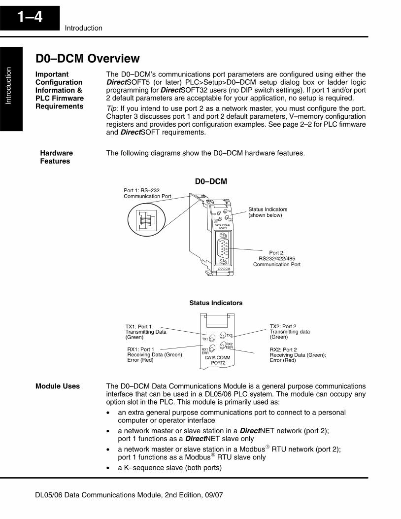
The following diagrams show the D0–DCM hardware features.
Status Indicators(shown below)
Port 1: RS–232 Communication Port
Port 2:RS232/422/485
Communication Port
TX1: Port 1Transmitting Data(Green)
RX1: Port 1Receiving Data (Green);Error (Red)
Status Indicators
TX1TX2
DATA COMMPORT2
RX1ERR
RX2ERR
TX2: Port 2Transmitting data(Green)
RX2: Port 2 Receiving Data (Green);Error (Red)
D0–DCM
The D0–DCM Data Communications Module is a general purpose communicationsinterface that can be used in a DL05/06 PLC system. The module can occupy anyoption slot in the PLC. This module is primarily used as:
• an extra general purpose communications port to connect to a personalcomputer or operator interface
• a network master or slave station in a DirectNET network (port 2);port 1 functions as a DirectNET slave only
• a network master or slave station in a Modbus� RTU network (port 2); port 1 functions as a Modbus� RTU slave only
• a K–sequence slave (both ports)
ImportantConfigurationInformation & PLC FirmwareRequirements
Hardware Features
Module Uses
IntroductionInstallation and
Safety G
uidelines1–5
Introduction
DL05/06 Data Communications Module, 2nd Edition, 09/07
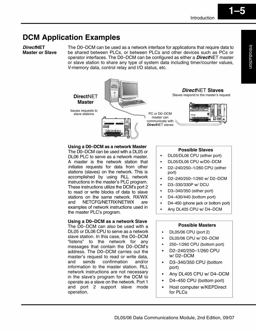
DCM Application ExamplesThe D0–DCM can be used as a network interface for applications that require data tobe shared between PLCs, or between PLCs and other devices such as PCs oroperator interfaces. The D0–DCM can be configured as either a DirectNET masteror slave station to share any type of system data including timer/counter values,V-memory data, control relay and I/O status, etc.
DirectNET SlavesSlaves respond to the master’s request
PC or D0–DCMmaster can
communicate withDirectNET slaves
DirectNETMaster
Issues requests toslave stations
Using a D0–DCM as a network Master The D0–DCM can be used with a DL05 orDL06 PLC to serve as a network master.A master is the network station thatinitiates requests for data from otherstations (slaves) on the network. This isaccomplished by using RLL networkinstructions in the master’s PLC program.These instructions utilize the DCM’s port 2to read or write blocks of data to slavestations on the same network. RX/WXand NETCFG/NETRX/NETWX areexamples of network instructions used inthe master PLC’s program.
Possible Slaves� DL05/DL06 CPU (either port)
� DL05/DL06 CPU w/D0–DCM
� D2–240/250–1/260 CPU (either port)
� D2–240/250–1/260 w/ D2–DCM
� D3–330/330P w/ DCU
� D3–340/350 (either port)
� D4–430/440 (bottom port)
� D4–450 (phone jack or bottom port)
� Any DL405 CPU w/ D4–DCM
Using a D0–DCM as a network SlaveThe D0–DCM can also be used with aDL05 or DL06 CPU to serve as a networkslave station. In this case, the D0–DCM“listens” to the network for anymessages that contain the D0–DCM’saddress. The D0–DCM carries out themaster’s request to read or write data,and sends confirmation and/orinformation to the master station. RLLnetwork instructions are not necessaryin the slave’s program for the DCM tooperate as a slave on the network. Port 1and port 2 support slave modeoperation.
Possible Masters� DL05/06 CPU (port 2)
� DL05/06 CPU w/ D0–DCM
� 250–1/260 CPU (bottom port)
� D2–240/250–1/260 CPUw/ D2–DCM
� D3–340/350 CPU (bottomport)
� Any DL405 CPU w/ D4–DCM� D4–450 CPU (bottom port)� Host computer w/KEPDirect
for PLCs
DirectNET Master or Slave
Intr
oduc
tion
Inst
alla
tion
and
Saf
ety
Gui
delin
es1–6
Introduction
DL05/06 Data Communications Module, 2nd Edition, 09/07
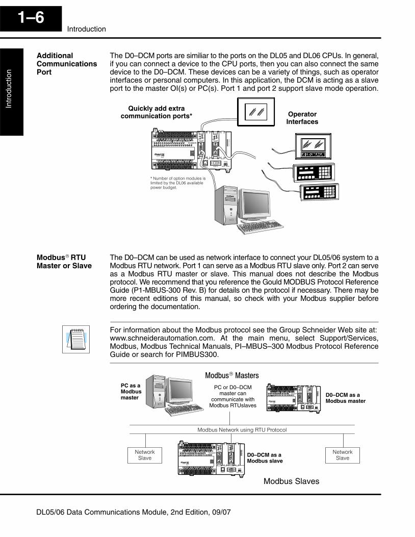
The D0–DCM ports are similiar to the ports on the DL05 and DL06 CPUs. In general,if you can connect a device to the CPU ports, then you can also connect the samedevice to the D0–DCM. These devices can be a variety of things, such as operatorinterfaces or personal computers. In this application, the DCM is acting as a slaveport to the master OI(s) or PC(s). Port 1 and port 2 support slave mode operation.
Quickly add extracommunication ports*
����������� ���������������� ������ �������������������������� �
OperatorInterfaces
The D0–DCM can be used as network interface to connect your DL05/06 system to aModbus RTU network. Port 1 can serve as a Modbus RTU slave only. Port 2 can serveas a Modbus RTU master or slave. This manual does not describe the Modbusprotocol. We recommend that you reference the Gould MODBUS Protocol ReferenceGuide (P1-MBUS-300 Rev. B) for details on the protocol if necessary. There may bemore recent editions of this manual, so check with your Modbus supplier beforeordering the documentation.
For information about the Modbus protocol see the Group Schneider Web site at:www.schneiderautomation.com. At the main menu, select Support/Services,Modbus, Modbus Technical Manuals, PI–MBUS–300 Modbus Protocol ReferenceGuide or search for PIMBUS300.
�������� ��������� !"�# $�
�� ��%����
D0–DCM as aModbus slave
Modbus Slaves
�� ��%����
������®������
D0–DCM as aModbus master
PC as aModbusmaster
PC or D0–DCMmaster can
communicate withModbus RTUslaves
AdditionalCommunicationsPort
Modbus® RTUMaster or Slave
12Installation, NetworkCabling and ModuleSpecifications
In This Chapter. . . .— Inserting the D0–DCM into the PLC— Building the Communication Cable— Wiring Diagrams— Module Specifications
Inst
alla
tion
and
Mod
ule
Spe
cific
atio
nsIn
stal
latio
n an
dS
afet
y G
uide
lines
2–2Installation and Module Specifications
DL05/06 Data Communications Module, 2nd Edition, 09/07
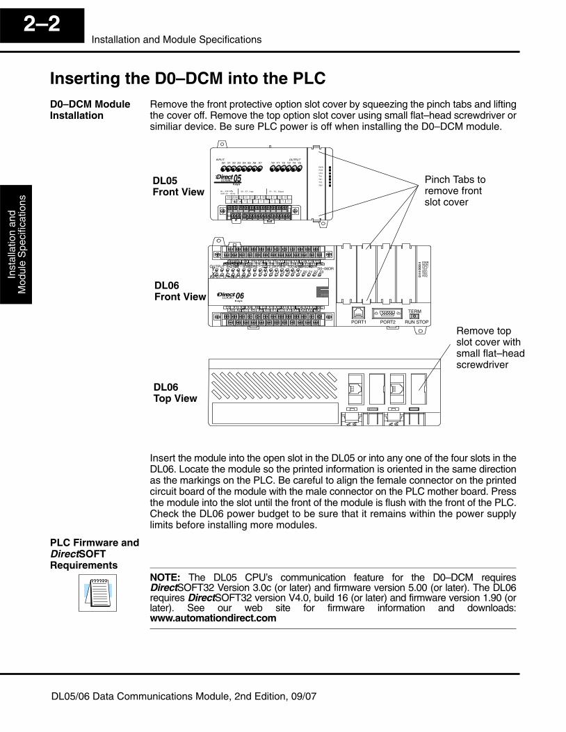
Inserting the D0–DCM into the PLCRemove the front protective option slot cover by squeezing the pinch tabs and liftingthe cover off. Remove the top option slot cover using small flat–head screwdriver orsimiliar device. Be sure PLC power is off when installing the D0–DCM module.
Pinch Tabs toremove frontslot cover
C0 C4C2X1 X3 X4 X6 X11 X13X14 X16 X21 X23N.C.C1 C3X2 X5 X7 X10 X12 X15X17 X20 X22X0 N.C.
AC(N) 24V0V
N.C.C1 C3Y0 Y15Y12Y10 Y17Y7Y5Y2
C0 C2 Y16Y14Y13Y11Y6Y4Y3Y1LGG
AC(L)2.0AOUTPUT: 6–240V50 – 60Hz2.0A,6 – 27V
INPUT: 12 – 24V3 – 15mA
YX
40VA50–60HzPWR: 100–240V
0 1 2 3 4 5 6 7 10 11 12 13 14 15 16 17 20 21 22 23
PORT1 RUN STOP
PWRRUNCPUTX1RX1TX2RX2
D0–06DR
PORT2
TERM
DL05Front View
DL06Front View
DL06Top View
Remove topslot cover withsmall flat–headscrewdriver
Insert the module into the open slot in the DL05 or into any one of the four slots in theDL06. Locate the module so the printed information is oriented in the same directionas the markings on the PLC. Be careful to align the female connector on the printedcircuit board of the module with the male connector on the PLC mother board. Pressthe module into the slot until the front of the module is flush with the front of the PLC.Check the DL06 power budget to be sure that it remains within the power supplylimits before installing more modules.
NOTE: The DL05 CPU’s communication feature for the D0–DCM requiresDirectSOFT32 Version 3.0c (or later) and firmware version 5.00 (or later). The DL06requires DirectSOFT32 version V4.0, build 16 (or later) and firmware version 1.90 (orlater). See our web site for firmware information and downloads:www.automationdirect.com
D0–DCM ModuleInstallation
PLC Firmware andDirectSOFTRequirements
Installation andS
afety Guidelines
Installation andM
odule Specifications
2–3Installation and Module Specifications
DL05/06 Data Communications Module, 2nd Edition, 09/07
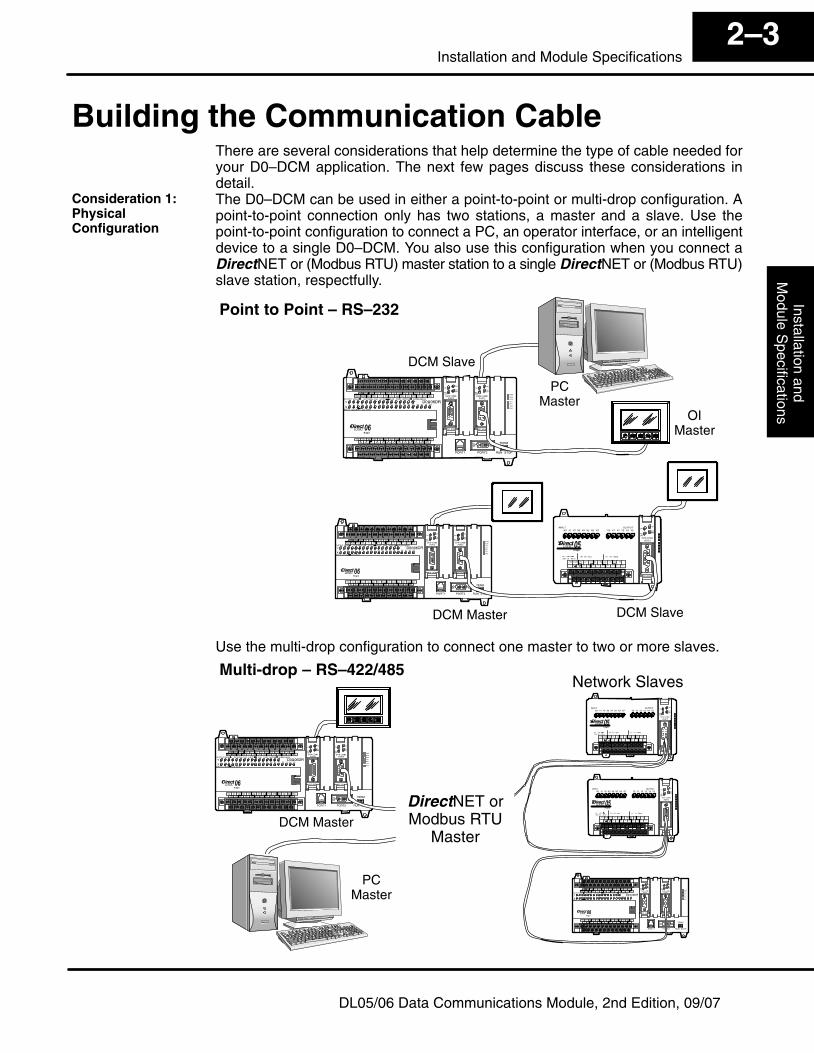
Building the Communication CableThere are several considerations that help determine the type of cable needed foryour D0–DCM application. The next few pages discuss these considerations indetail.The D0–DCM can be used in either a point-to-point or multi-drop configuration. Apoint-to-point connection only has two stations, a master and a slave. Use thepoint-to-point configuration to connect a PC, an operator interface, or an intelligentdevice to a single D0–DCM. You also use this configuration when you connect aDirectNET or (Modbus RTU) master station to a single DirectNET or (Modbus RTU)slave station, respectfully.
Point to Point – RS–232
DCM Master DCM Slave
DCM Slave
PCMaster
OIMaster
Use the multi-drop configuration to connect one master to two or more slaves.
Network Slaves
DCM Master
Multi-drop – RS–422/485
PCMaster
DirectNET orModbus RTU
Master
Consideration 1:PhysicalConfiguration
Inst
alla
tion
and
Mod
ule
Spe
cific
atio
nsIn
stal
latio
n an
dS
afet
y G
uide
lines
2–4Installation and Module Specifications
DL05/06 Data Communications Module, 2nd Edition, 09/07
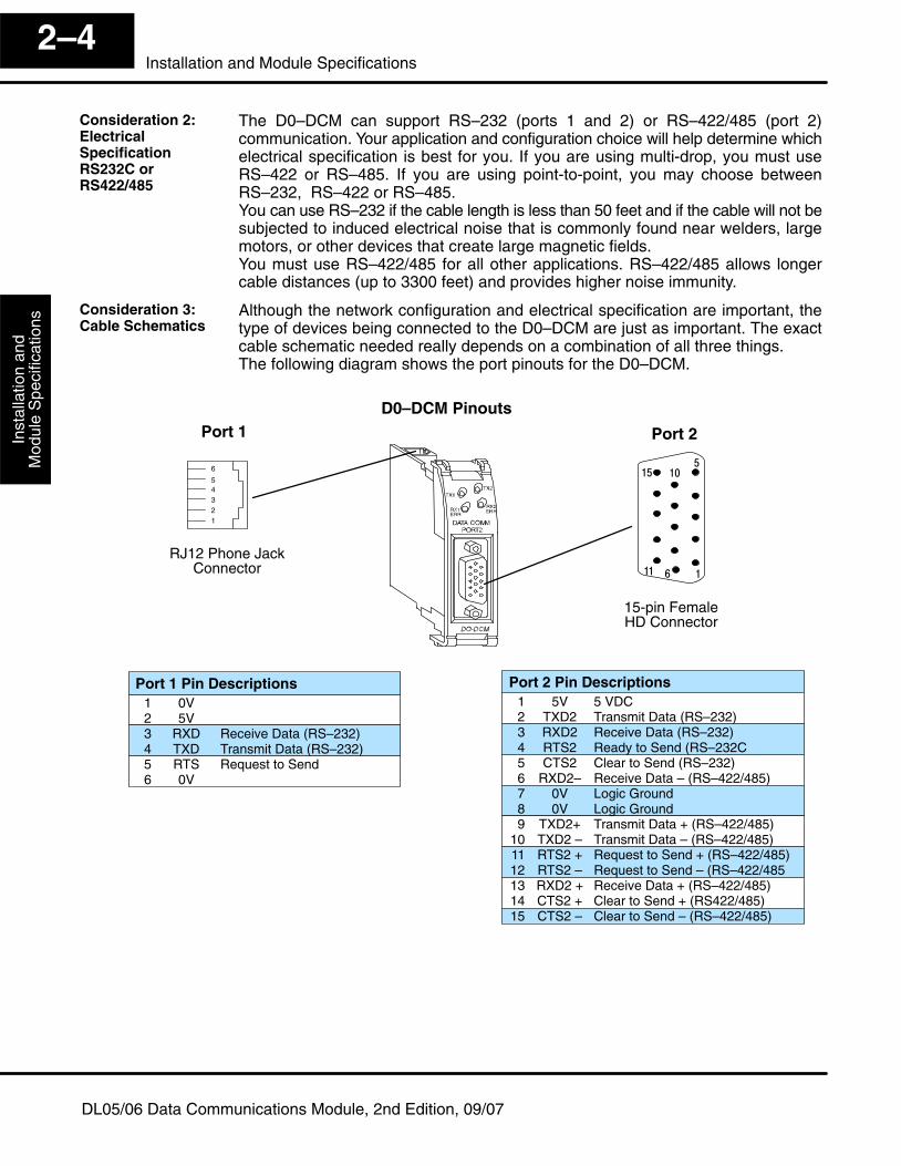
The D0–DCM can support RS–232 (ports 1 and 2) or RS–422/485 (port 2)communication. Your application and configuration choice will help determine whichelectrical specification is best for you. If you are using multi-drop, you must useRS–422 or RS–485. If you are using point-to-point, you may choose betweenRS–232, RS–422 or RS–485.You can use RS–232 if the cable length is less than 50 feet and if the cable will not besubjected to induced electrical noise that is commonly found near welders, largemotors, or other devices that create large magnetic fields.You must use RS–422/485 for all other applications. RS–422/485 allows longercable distances (up to 3300 feet) and provides higher noise immunity.
Although the network configuration and electrical specification are important, thetype of devices being connected to the D0–DCM are just as important. The exactcable schematic needed really depends on a combination of all three things.The following diagram shows the port pinouts for the D0–DCM.
D0–DCM PinoutsPort 1
15-pin FemaleHD Connector
�
�
��
�� ��
�
Port 2
Port 2 Pin Descriptions1 5V 5 VDC2 TXD2 Transmit Data (RS–232)3 RXD2 Receive Data (RS–232)4 RTS2 Ready to Send (RS–232C5 CTS2 Clear to Send (RS–232)6 RXD2– Receive Data – (RS–422/485)7 0V Logic Ground8 0V Logic Ground9 TXD2+ Transmit Data + (RS–422/485)
10 TXD2 – Transmit Data – (RS–422/485)11 RTS2 + Request to Send + (RS–422/485)12 RTS2 – Request to Send – (RS–422/48513 RXD2 + Receive Data + (RS–422/485)14 CTS2 + Clear to Send + (RS422/485)15 CTS2 – Clear to Send – (RS–422/485)
Port 1 Pin Descriptions1 0V2 5V3 RXD Receive Data (RS–232)4 TXD Transmit Data (RS–232)5 RTS Request to Send6 0V
12345
6
RJ12 Phone JackConnector
Consideration 2:ElectricalSpecificationRS232C orRS422/485
Consideration 3:Cable Schematics
Installation andS
afety Guidelines
Installation andM
odule Specifications
2–5Installation and Module Specifications
DL05/06 Data Communications Module, 2nd Edition, 09/07
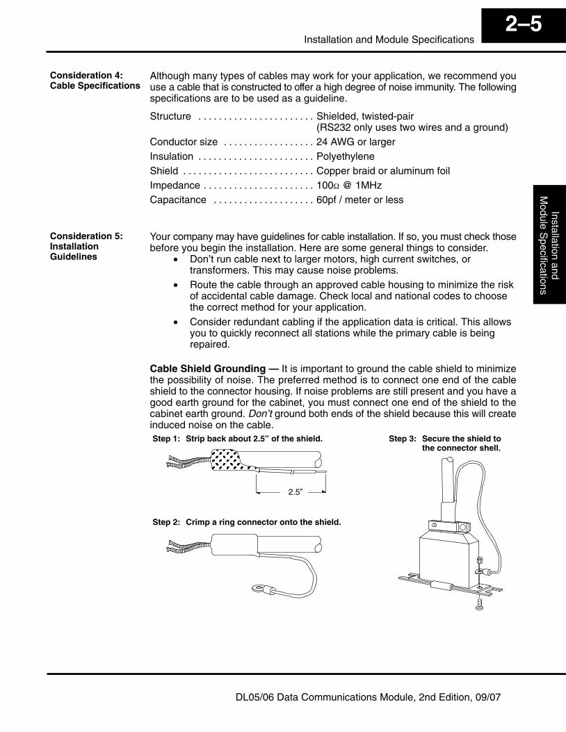
Although many types of cables may work for your application, we recommend youuse a cable that is constructed to offer a high degree of noise immunity. The followingspecifications are to be used as a guideline.
Structure Shielded, twisted-pair. . . . . . . . . . . . . . . . . . . . . . . (RS232 only uses two wires and a ground)
Conductor size 24 AWG or larger. . . . . . . . . . . . . . . . . . Insulation Polyethylene. . . . . . . . . . . . . . . . . . . . . . . Shield Copper braid or aluminum foil. . . . . . . . . . . . . . . . . . . . . . . . . . Impedance 100� @ 1MHz. . . . . . . . . . . . . . . . . . . . . . Capacitance 60pf / meter or less. . . . . . . . . . . . . . . . . . . .
Your company may have guidelines for cable installation. If so, you must check thosebefore you begin the installation. Here are some general things to consider.
• Don’t run cable next to larger motors, high current switches, ortransformers. This may cause noise problems.
• Route the cable through an approved cable housing to minimize the riskof accidental cable damage. Check local and national codes to choosethe correct method for your application.
• Consider redundant cabling if the application data is critical. This allowsyou to quickly reconnect all stations while the primary cable is beingrepaired.
Cable Shield Grounding — It is important to ground the cable shield to minimizethe possibility of noise. The preferred method is to connect one end of the cableshield to the connector housing. If noise problems are still present and you have agood earth ground for the cabinet, you must connect one end of the shield to thecabinet earth ground. Don’t ground both ends of the shield because this will createinduced noise on the cable.
ÎÎÎÎÎÎÎÎÎÎÎÎÎÎÎ
2.5”
Step 1: Strip back about 2.5” of the shield.
Step 2: Crimp a ring connector onto the shield.
Step 3: Secure the shield to the connector shell.
Consideration 4:Cable Specifications
Consideration 5:InstallationGuidelines
Inst
alla
tion
and
Mod
ule
Spe
cific
atio
nsIn
stal
latio
n an
dS
afet
y G
uide
lines
2–6Installation and Module Specifications
DL05/06 Data Communications Module, 2nd Edition, 09/07
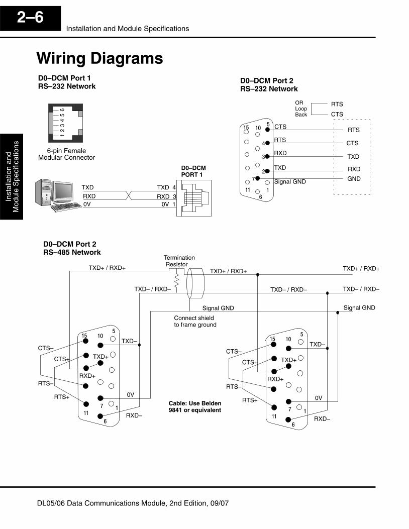
Wiring Diagrams
6-pin FemaleModular Connector
12
34
56
D0–DCM Port 1RS–232 Network
D0–DCMPORT 1
0V 0V 1
TXD 4
RXD 3RXD
TXDSignal GND
RXD
�
�
�
��
��
��
TXD
�
�
�
TXD
RXD
GND
RTS
CTS RTS
CTS
RTSORLoopBack
D0–DCM Port 2RS–232 Network
CTS
TXD+ / RXD+
TXD– / RXD–
Termination Resistor
Signal GND
Connect shieldto frame ground
Cable: Use Belden9841 or equivalent
TXD–
RXD–
0V
TXD+
�
����
RXD+
�
�
�
��
TXD+ / RXD+
TXD– / RXD–
TXD+ / RXD+
TXD– / RXD–
Signal GND
RTS+
RTS–
CTS+
CTS–
D0–DCM Port 2RS–485 Network
TXD–
RXD–
0V
TXD+
�
����
RXD+
�
�
�
��
RTS+
RTS–
CTS+
CTS–
Installation andS
afety Guidelines
Installation andM
odule Specifications
2–7Installation and Module Specifications
DL05/06 Data Communications Module, 2nd Edition, 09/07
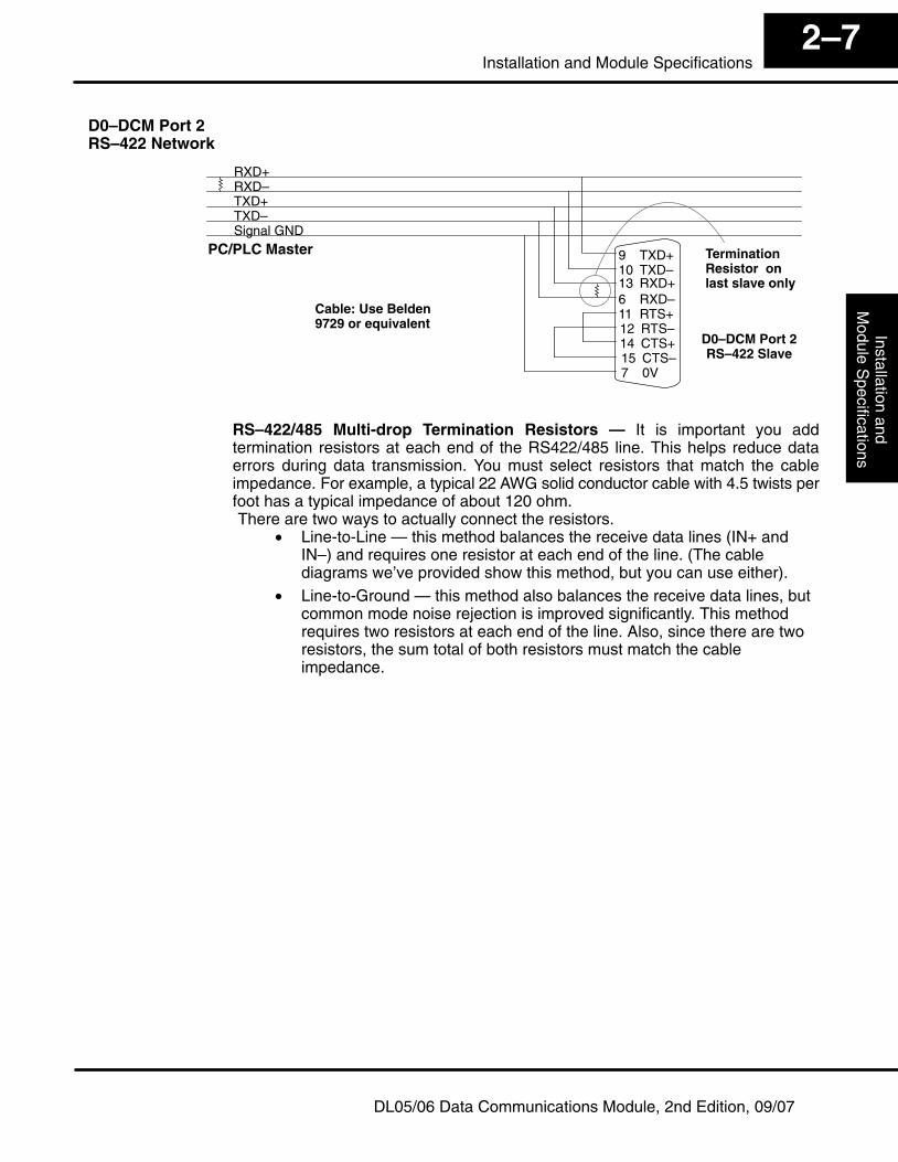
RXD+RXD–TXD+TXD–Signal GND
D0–DCM Port 2RS–422 Slave
9 TXD+10 TXD–13 RXD+6 RXD–11 RTS+12 RTS–14 CTS+15 CTS–7 0V
PC/PLC Master TerminationResistor onlast slave only
D0–DCM Port 2RS–422 Network
Cable: Use Belden9729 or equivalent
RS–422/485 Multi-drop Termination Resistors — It is important you addtermination resistors at each end of the RS422/485 line. This helps reduce dataerrors during data transmission. You must select resistors that match the cableimpedance. For example, a typical 22 AWG solid conductor cable with 4.5 twists perfoot has a typical impedance of about 120 ohm.There are two ways to actually connect the resistors.
• Line-to-Line — this method balances the receive data lines (IN+ andIN–) and requires one resistor at each end of the line. (The cablediagrams we’ve provided show this method, but you can use either).
• Line-to-Ground — this method also balances the receive data lines, butcommon mode noise rejection is improved significantly. This methodrequires two resistors at each end of the line. Also, since there are tworesistors, the sum total of both resistors must match the cableimpedance.
Inst
alla
tion
and
Mod
ule
Spe
cific
atio
nsIn
stal
latio
n an
dS
afet
y G
uide
lines
2–8Installation and Module Specifications
DL05/06 Data Communications Module, 2nd Edition, 09/07
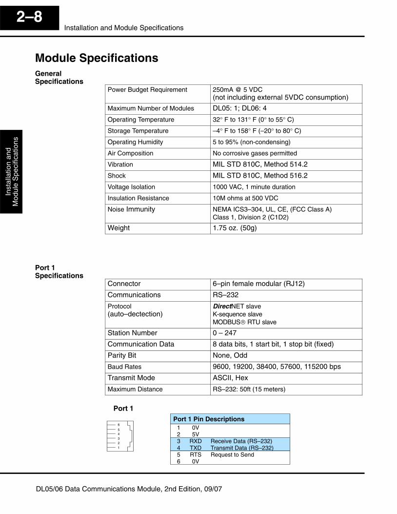
Module Specifications
Power Budget Requirement 250mA @ 5 VDC (not including external 5VDC consumption)
Maximum Number of Modules DL05: 1; DL06: 4
Operating Temperature 32° F to 131° F (0° to 55° C)
Storage Temperature –4° F to 158° F (–20° to 80° C)
Operating Humidity 5 to 95% (non-condensing)
Air Composition No corrosive gases permitted
Vibration MIL STD 810C, Method 514.2
Shock MIL STD 810C, Method 516.2
Voltage Isolation 1000 VAC, 1 minute duration
Insulation Resistance 10M ohms at 500 VDC
Noise Immunity NEMA ICS3–304, UL, CE, (FCC Class A)Class 1, Division 2 (C1D2)
Weight 1.75 oz. (50g)
Connector 6–pin female modular (RJ12)
Communications RS–232
Protocol(auto–dectection)
DirectNET slaveK-sequence slaveMODBUS® RTU slave
Station Number 0 – 247
Communication Data 8 data bits, 1 start bit, 1 stop bit (fixed)
Parity Bit None, Odd
Baud Rates 9600, 19200, 38400, 57600, 115200 bps
Transmit Mode ASCII, Hex
Maximum Distance RS–232: 50ft (15 meters)
Port 1Port 1 Pin Descriptions
1 0V2 5V3 RXD Receive Data (RS–232)4 TXD Transmit Data (RS–232)5 RTS Request to Send6 0V
12345
6
GeneralSpecifications
Port 1Specifications
Installation andS
afety Guidelines
Installation andM
odule Specifications
2–9Installation and Module Specifications
DL05/06 Data Communications Module, 2nd Edition, 09/07
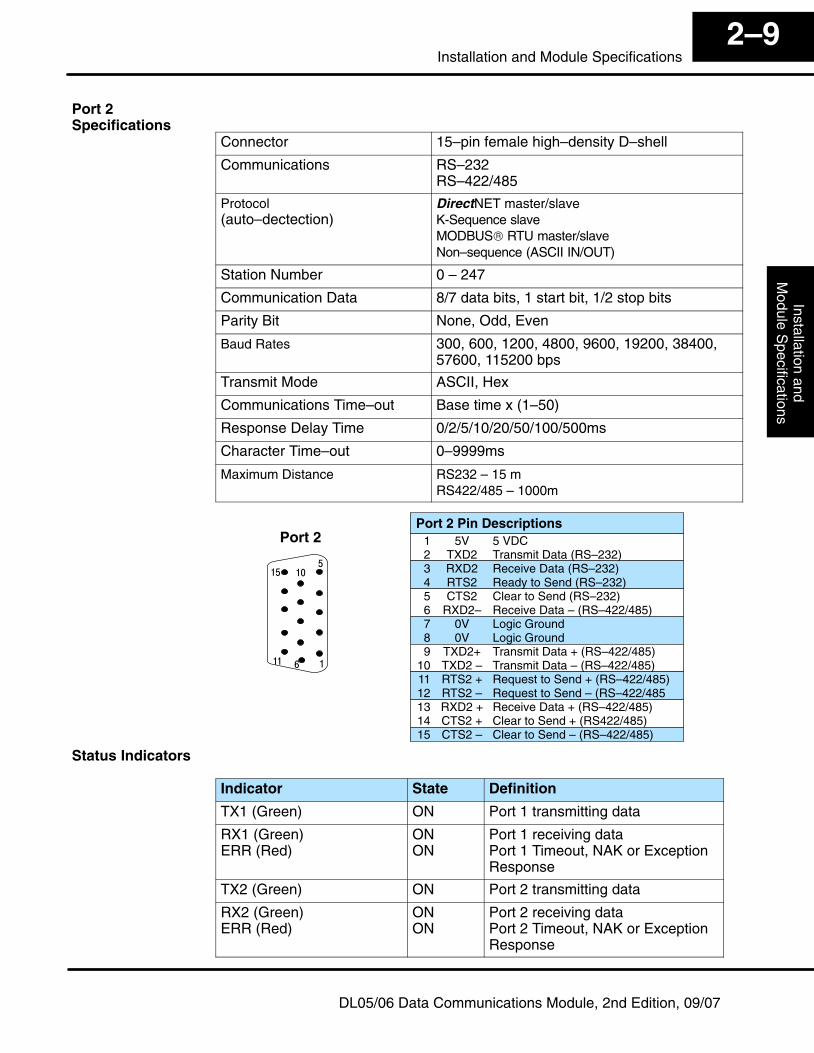
Connector 15–pin female high–density D–shell
Communications RS–232RS–422/485
Protocol(auto–dectection)
DirectNET master/slaveK-Sequence slaveMODBUS® RTU master/slaveNon–sequence (ASCII IN/OUT)
Station Number 0 – 247
Communication Data 8/7 data bits, 1 start bit, 1/2 stop bits
Parity Bit None, Odd, Even
Baud Rates 300, 600, 1200, 4800, 9600, 19200, 38400,57600, 115200 bps
Transmit Mode ASCII, Hex
Communications Time–out Base time x (1–50)
Response Delay Time 0/2/5/10/20/50/100/500ms
Character Time–out 0–9999ms
Maximum Distance RS232 – 15 mRS422/485 – 1000m
�
�
��
�� ��
�
Port 2Port 2 Pin Descriptions
1 5V 5 VDC2 TXD2 Transmit Data (RS–232)3 RXD2 Receive Data (RS–232)4 RTS2 Ready to Send (RS–232)5 CTS2 Clear to Send (RS–232)6 RXD2– Receive Data – (RS–422/485)7 0V Logic Ground8 0V Logic Ground9 TXD2+ Transmit Data + (RS–422/485)
10 TXD2 – Transmit Data – (RS–422/485)11 RTS2 + Request to Send + (RS–422/485)12 RTS2 – Request to Send – (RS–422/48513 RXD2 + Receive Data + (RS–422/485)14 CTS2 + Clear to Send + (RS422/485)15 CTS2 – Clear to Send – (RS–422/485)
Indicator State Definition
TX1 (Green) ON Port 1 transmitting data
RX1 (Green)ERR (Red)
ONON
Port 1 receiving dataPort 1 Timeout, NAK or ExceptionResponse
TX2 (Green) ON Port 2 transmitting data
RX2 (Green)ERR (Red)
ONON
Port 2 receiving dataPort 2 Timeout, NAK or ExceptionResponse
Port 2Specifications
Status Indicators
D0–DCM ModuleSetup
3
In This Chapter. . . .— Important Module Configuration Information— Using DirectSOFT5 to Configure DCM Ports— DCM Port 1 and Port 2 Configuration Registers— Using Ladder Logic to Configure DCM Ports (DL05)— Using Ladder Logic to Configure DCM Ports (DL06)
DC
M P
ort
Con
figur
atio
nIn
stal
latio
n an
dS
afet
y G
uide
lines
3–2D0–DCM Setup
DL05/06 Data Communications Module, 2nd Edition, 09/07
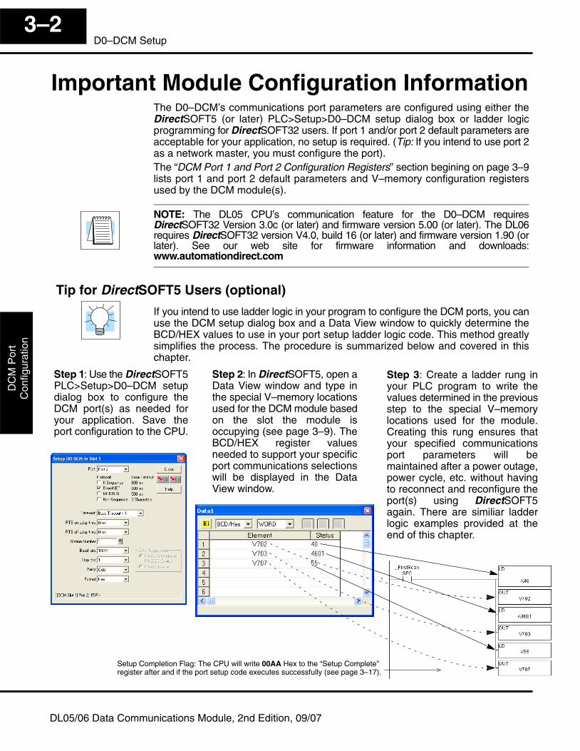
Important Module Configuration InformationThe D0–DCM’s communications port parameters are configured using either theDirectSOFT5 (or later) PLC>Setup>D0–DCM setup dialog box or ladder logicprogramming for DirectSOFT32 users. If port 1 and/or port 2 default parameters areacceptable for your application, no setup is required. (Tip: If you intend to use port 2as a network master, you must configure the port).The “DCM Port 1 and Port 2 Configuration Registers” section begining on page 3–9lists port 1 and port 2 default parameters and V–memory configuration registersused by the DCM module(s).
NOTE: The DL05 CPU’s communication feature for the D0–DCM requiresDirectSOFT32 Version 3.0c (or later) and firmware version 5.00 (or later). The DL06requires DirectSOFT32 version V4.0, build 16 (or later) and firmware version 1.90 (orlater). See our web site for firmware information and downloads:www.automationdirect.com
Tip for DirectSOFT5 Users (optional)
If you intend to use ladder logic in your program to configure the DCM ports, you canuse the DCM setup dialog box and a Data View window to quickly determine theBCD/HEX values to use in your port setup ladder logic code. This method greatlysimplifies the process. The procedure is summarized below and covered in thischapter.
Step 1: Use the DirectSOFT5PLC>Setup>D0–DCM setupdialog box to configure theDCM port(s) as needed foryour application. Save theport configuration to the CPU.
Step 2: In DirectSOFT5, open aData View window and type inthe special V–memory locationsused for the DCM module basedon the slot the module isoccupying (see page 3–9). TheBCD/HEX register valuesneeded to support your specificport communications selectionswill be displayed in the DataView window.
Step 3: Create a ladder rung inyour PLC program to write thevalues determined in the previousstep to the special V–memorylocations used for the module.Creating this rung ensures thatyour specified communicationsport parameters will bemaintained after a power outage,power cycle, etc. without havingto reconnect and reconfigure theport(s) using DirectSOFT5again. There are similiar ladderlogic examples provided at theend of this chapter.
Setup Completion Flag: The CPU will write 00AA Hex to the “Setup Complete”register after and if the port setup code executes successfully (see page 3–17).
DC
M P
ortC
onfigurationInstallation and
Safety G
uidelines3–3
D0–DCM Setup
DL05/06 Data Communications Module, 2nd Edition, 09/07
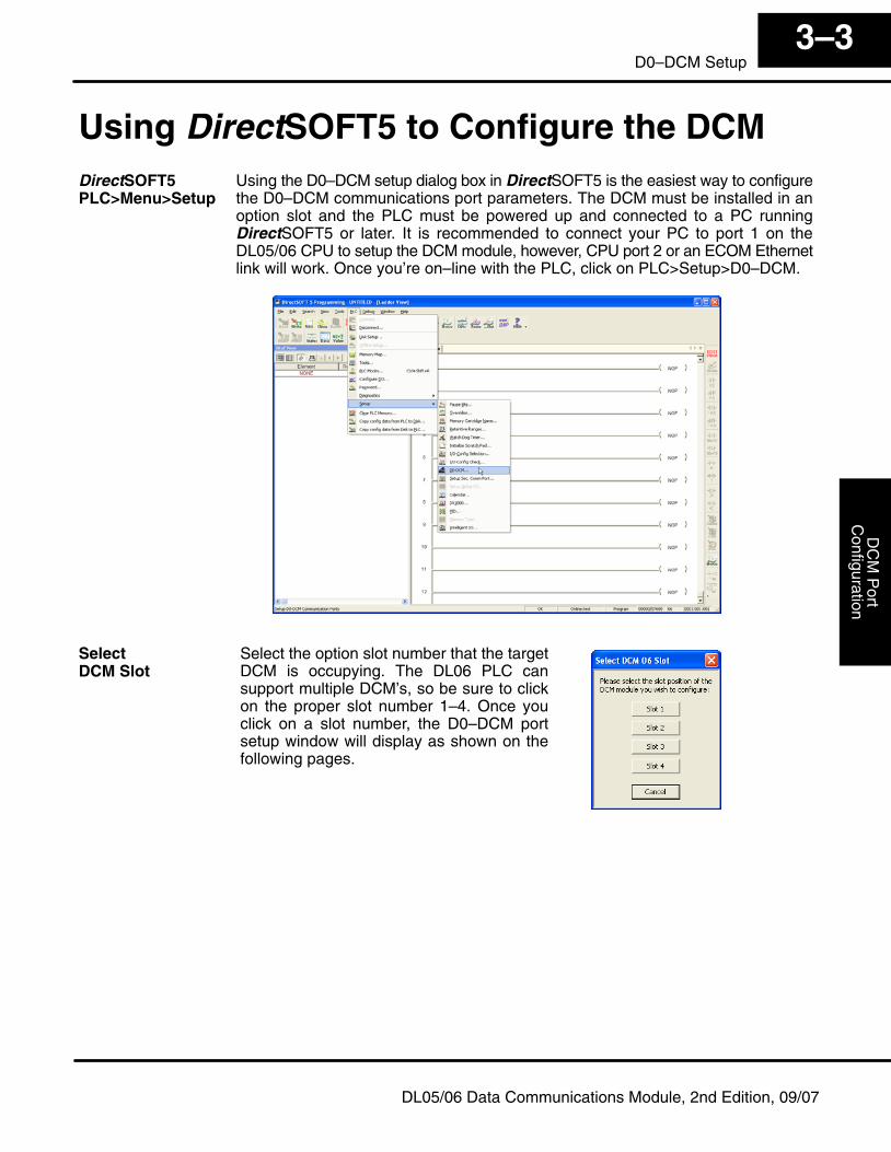
Using DirectSOFT5 to Configure the DCMUsing the D0–DCM setup dialog box in DirectSOFT5 is the easiest way to configurethe D0–DCM communications port parameters. The DCM must be installed in anoption slot and the PLC must be powered up and connected to a PC runningDirectSOFT5 or later. It is recommended to connect your PC to port 1 on theDL05/06 CPU to setup the DCM module, however, CPU port 2 or an ECOM Ethernetlink will work. Once you’re on–line with the PLC, click on PLC>Setup>D0–DCM.
Select the option slot number that the targetDCM is occupying. The DL06 PLC cansupport multiple DCM’s, so be sure to clickon the proper slot number 1–4. Once youclick on a slot number, the D0–DCM portsetup window will display as shown on thefollowing pages.
DirectSOFT5PLC>Menu>Setup
SelectDCM Slot
DC
M P
ort
Con
figur
atio
nIn
stal
latio
n an
dS
afet
y G
uide
lines
3–4D0–DCM Setup
DL05/06 Data Communications Module, 2nd Edition, 09/07
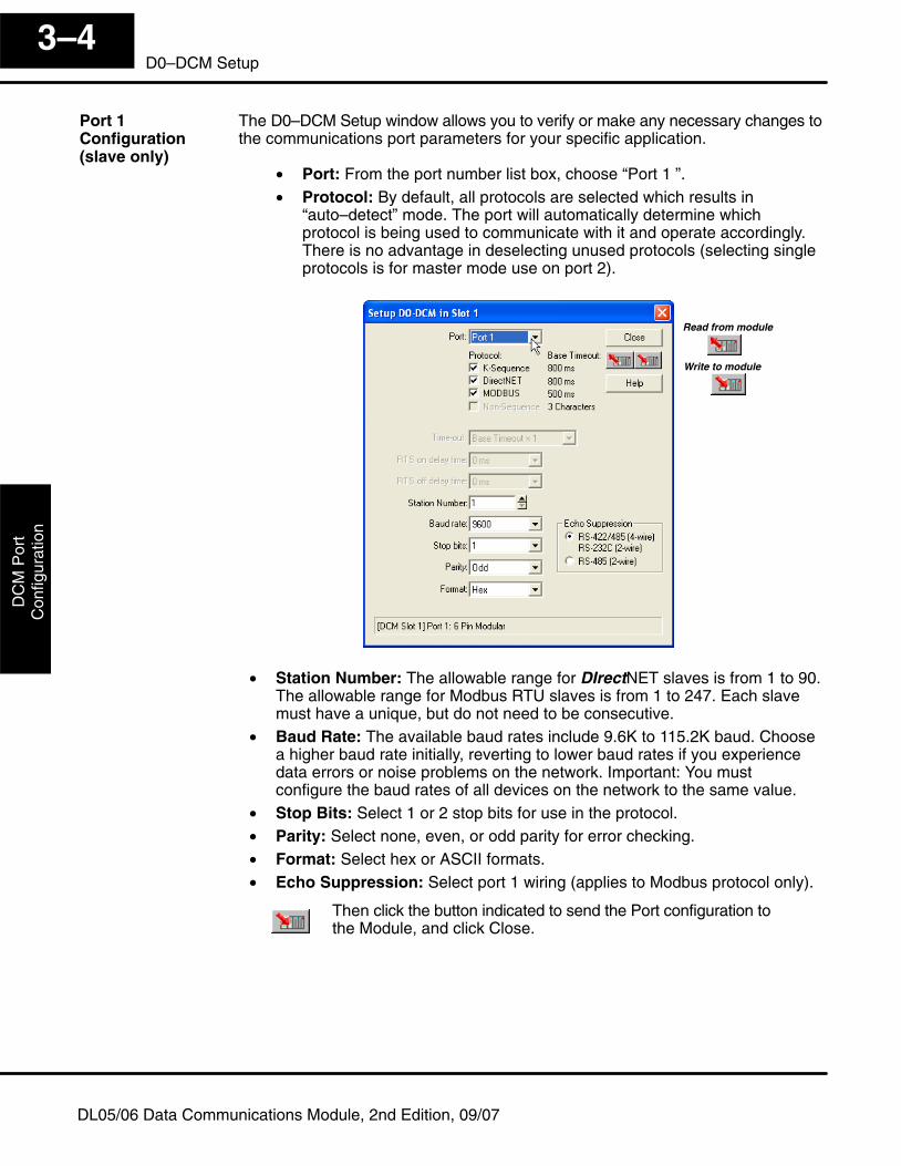
The D0–DCM Setup window allows you to verify or make any necessary changes tothe communications port parameters for your specific application.
• Port: From the port number list box, choose “Port 1 ”.• Protocol: By default, all protocols are selected which results in
“auto–detect” mode. The port will automatically determine whichprotocol is being used to communicate with it and operate accordingly.There is no advantage in deselecting unused protocols (selecting singleprotocols is for master mode use on port 2).
Read from module
Write to module
• Station Number: The allowable range for DIrectNET slaves is from 1 to 90.The allowable range for Modbus RTU slaves is from 1 to 247. Each slavemust have a unique, but do not need to be consecutive.
• Baud Rate: The available baud rates include 9.6K to 115.2K baud. Choosea higher baud rate initially, reverting to lower baud rates if you experiencedata errors or noise problems on the network. Important: You mustconfigure the baud rates of all devices on the network to the same value.
• Stop Bits: Select 1 or 2 stop bits for use in the protocol.• Parity: Select none, even, or odd parity for error checking.• Format: Select hex or ASCII formats.• Echo Suppression: Select port 1 wiring (applies to Modbus protocol only).
Then click the button indicated to send the Port configuration tothe Module, and click Close.
Port 1Configuration(slave only)
DC
M P
ortC
onfigurationInstallation and
Safety G
uidelines3–5
D0–DCM Setup
DL05/06 Data Communications Module, 2nd Edition, 09/07
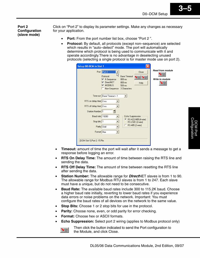
Click on “Port 2” to display its parameter settings. Make any changes as necessaryfor your application.
• Port: From the port number list box, choose “Port 2 ”.• Protocol: By default, all protocols (except non–sequence) are selected
which results in “auto–detect” mode. The port will automaticallydetermine which protocol is being used to communicate with it andoperate accordingly.There is no advantage in deselecting unusedprotocols (selecting a single protocol is for master mode use on port 2).
Read from module
Write to module
• Timeout: amount of time the port will wait after it sends a message to get aresponse before logging an error.
• RTS On Delay Time: The amount of time between raising the RTS line andsending the data.
• RTS Off Delay Time: The amount of time between resetting the RTS lineafter sending the data.
• Station Number: The allowable range for DIrectNET slaves is from 1 to 90.The allowable range for Modbus RTU slaves is from 1 to 247. Each slavemust have a unique, but do not need to be consecutive.
• Baud Rate: The available baud rates include 300 to 115.2K baud. Choosea higher baud rate initially, reverting to lower baud rates if you experiencedata errors or noise problems on the network. Important: You mustconfigure the baud rates of all devices on the network to the same value.
• Stop Bits: Choose 1 or 2 stop bits for use in the protocol.• Parity: Choose none, even, or odd parity for error checking.• Format: Choose hex or ASCII formats.• Echo Suppression: Select port 2 wiring (applies to Modbus protocol only)
Then click the button indicated to send the Port configuration tothe Module, and click Close.
Port 2Configuration(slave mode)
DC
M P
ort
Con
figur
atio
nIn
stal
latio
n an
dS
afet
y G
uide
lines
3–6D0–DCM Setup
DL05/06 Data Communications Module, 2nd Edition, 09/07
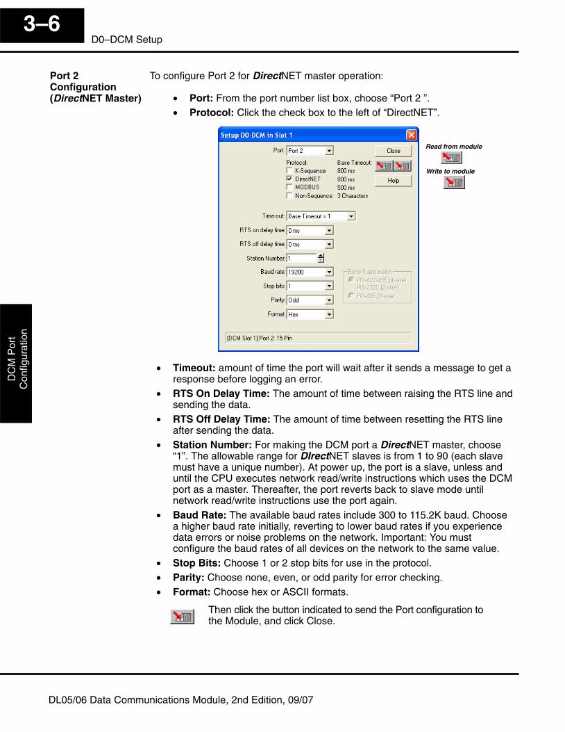
To configure Port 2 for DirectNET master operation:
• Port: From the port number list box, choose “Port 2 ”.• Protocol: Click the check box to the left of “DirectNET”.
Read from module
Write to module
• Timeout: amount of time the port will wait after it sends a message to get aresponse before logging an error.
• RTS On Delay Time: The amount of time between raising the RTS line andsending the data.
• RTS Off Delay Time: The amount of time between resetting the RTS lineafter sending the data.
• Station Number: For making the DCM port a DirectNET master, choose“1”. The allowable range for DIrectNET slaves is from 1 to 90 (each slavemust have a unique number). At power up, the port is a slave, unless anduntil the CPU executes network read/write instructions which uses the DCMport as a master. Thereafter, the port reverts back to slave mode untilnetwork read/write instructions use the port again.
• Baud Rate: The available baud rates include 300 to 115.2K baud. Choosea higher baud rate initially, reverting to lower baud rates if you experiencedata errors or noise problems on the network. Important: You mustconfigure the baud rates of all devices on the network to the same value.
• Stop Bits: Choose 1 or 2 stop bits for use in the protocol.• Parity: Choose none, even, or odd parity for error checking.• Format: Choose hex or ASCII formats.
Then click the button indicated to send the Port configuration tothe Module, and click Close.
Port 2Configuration(DirectNET Master)
DC
M P
ortC
onfigurationInstallation and
Safety G
uidelines3–7
D0–DCM Setup
DL05/06 Data Communications Module, 2nd Edition, 09/07
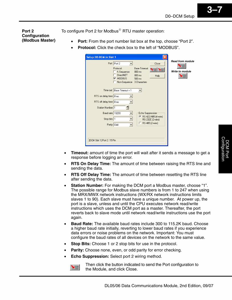
To configure Port 2 for Modbus� RTU master operation:
• Port: From the port number list box at the top, choose “Port 2”.
• Protocol: Click the check box to the left of “MODBUS”.
Read from module
Write to module
• Timeout: amount of time the port will wait after it sends a message to get aresponse before logging an error.
• RTS On Delay Time: The amount of time between raising the RTS line andsending the data.
• RTS Off Delay Time: The amount of time between resetting the RTS lineafter sending the data.
• Station Number: For making the DCM port a Modbus master, choose “1”.The possible range for Modbus slave numbers is from 1 to 247 when usingthe MRX/MWX network instructions (WX/RX network instructions limitsslaves 1 to 90). Each slave must have a unique number. At power up, theport is a slave, unless and until the CPU executes network read/writeinstructions which uses the DCM port as a master. Thereafter, the portreverts back to slave mode until network read/write instructions use the portagain.
• Baud Rate: The available baud rates include 300 to 115.2K baud. Choosea higher baud rate initially, reverting to lower baud rates if you experiencedata errors or noise problems on the network. Important: You mustconfigure the baud rates of all devices on the network to the same value.
• Stop Bits: Choose 1 or 2 stop bits for use in the protocol.
• Parity: Choose none, even, or odd parity for error checking.
• Echo Suppression: Select port 2 wiring method.
Then click the button indicated to send the Port configuration tothe Module, and click Close.
Port 2Configuration(Modbus Master)
DC
M P
ort
Con
figur
atio
nIn
stal
latio
n an
dS
afet
y G
uide
lines
3–8D0–DCM Setup
DL05/06 Data Communications Module, 2nd Edition, 09/07
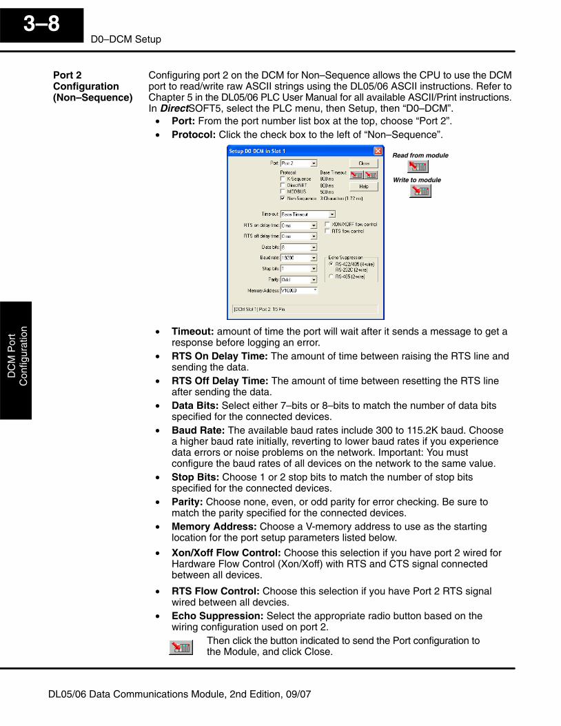
Configuring port 2 on the DCM for Non–Sequence allows the CPU to use the DCMport to read/write raw ASCII strings using the DL05/06 ASCII instructions. Refer toChapter 5 in the DL05/06 PLC User Manual for all available ASCII/Print instructions.In DirectSOFT5, select the PLC menu, then Setup, then “D0–DCM”.
• Port: From the port number list box at the top, choose “Port 2”.• Protocol: Click the check box to the left of “Non–Sequence”.
Read from module
Write to module
• Timeout: amount of time the port will wait after it sends a message to get aresponse before logging an error.
• RTS On Delay Time: The amount of time between raising the RTS line andsending the data.
• RTS Off Delay Time: The amount of time between resetting the RTS lineafter sending the data.
• Data Bits: Select either 7–bits or 8–bits to match the number of data bitsspecified for the connected devices.
• Baud Rate: The available baud rates include 300 to 115.2K baud. Choosea higher baud rate initially, reverting to lower baud rates if you experiencedata errors or noise problems on the network. Important: You mustconfigure the baud rates of all devices on the network to the same value.
• Stop Bits: Choose 1 or 2 stop bits to match the number of stop bitsspecified for the connected devices.
• Parity: Choose none, even, or odd parity for error checking. Be sure tomatch the parity specified for the connected devices.
• Memory Address: Choose a V-memory address to use as the startinglocation for the port setup parameters listed below.
• Xon/Xoff Flow Control: Choose this selection if you have port 2 wired forHardware Flow Control (Xon/Xoff) with RTS and CTS signal connectedbetween all devices.
• RTS Flow Control: Choose this selection if you have Port 2 RTS signalwired between all devcies.
• Echo Suppression: Select the appropriate radio button based on thewiring configuration used on port 2.
Then click the button indicated to send the Port configuration tothe Module, and click Close.
Port 2Configuration(Non–Sequence)
DC
M P
ortC
onfigurationInstallation and
Safety G
uidelines3–9
D0–DCM Setup
DL05/06 Data Communications Module, 2nd Edition, 09/07
D0–DCM Port Configuration Registers
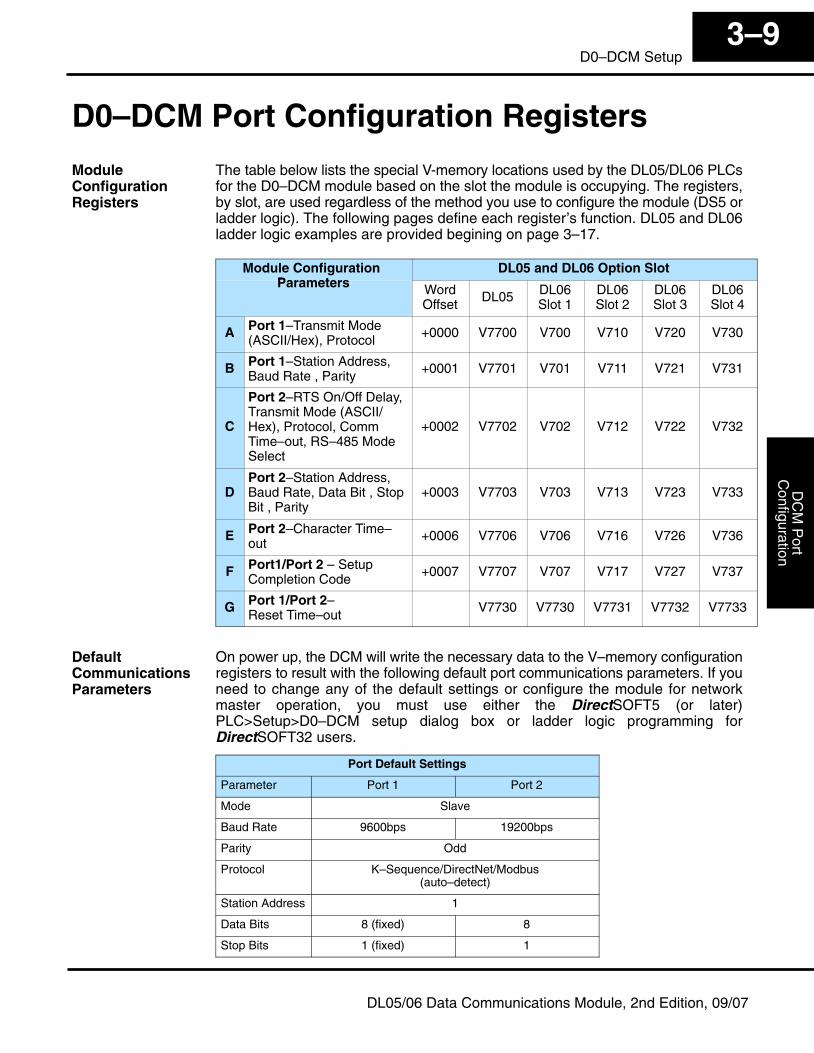
The table below lists the special V-memory locations used by the DL05/DL06 PLCsfor the D0–DCM module based on the slot the module is occupying. The registers,by slot, are used regardless of the method you use to configure the module (DS5 orladder logic). The following pages define each register’s function. DL05 and DL06ladder logic examples are provided begining on page 3–17.
Module Configuration Parameters
DL05 and DL06 Option SlotParameters Word
OffsetDL05 DL06
Slot 1DL06Slot 2
DL06Slot 3
DL06Slot 4
A Port 1–Transmit Mode(ASCII/Hex), Protocol
+0000 V7700 V700 V710 V720 V730
B Port 1–Station Address,Baud Rate , Parity
+0001 V7701 V701 V711 V721 V731
C
Port 2–RTS On/Off Delay,Transmit Mode (ASCII/Hex), Protocol, CommTime–out, RS–485 ModeSelect
+0002 V7702 V702 V712 V722 V732
DPort 2–Station Address,Baud Rate, Data Bit , StopBit , Parity
+0003 V7703 V703 V713 V723 V733
E Port 2–Character Time–out
+0006 V7706 V706 V716 V726 V736
F Port1/Port 2 – SetupCompletion Code
+0007 V7707 V707 V717 V727 V737
G Port 1/Port 2– Reset Time–out
V7730 V7730 V7731 V7732 V7733
On power up, the DCM will write the necessary data to the V–memory configurationregisters to result with the following default port communications parameters. If youneed to change any of the default settings or configure the module for networkmaster operation, you must use either the DirectSOFT5 (or later)PLC>Setup>D0–DCM setup dialog box or ladder logic programming forDirectSOFT32 users.
Port Default Settings
Parameter Port 1 Port 2
Mode Slave
Baud Rate 9600bps 19200bps
Parity Odd
Protocol K–Sequence/DirectNet/Modbus(auto–detect)
Station Address 1
Data Bits 8 (fixed) 8
Stop Bits 1 (fixed) 1
ModuleConfigurationRegisters
DefaultCommunicationsParameters
DC
M P
ort
Con
figur
atio
nIn
stal
latio
n an
dS
afet
y G
uide
lines
3–10D0–DCM Setup
DL05/06 Data Communications Module, 2nd Edition, 09/07
Protocol Selection: Slave mode (ports 1 and 2) – The default protocol setting forports 1 and 2 is refered to as “auto–detect” mode (all protocols are selected exceptnon–sequence for port 2). With this selection, the port will automatically determinewhich protocol is being used to communicate to it and operate accordingly. Thisselection is fine if you intend to program/monitor the CPU through the D0–DCMusing DirectSOFT, or connect it to an operator interface, etc. You can select a singleprotocol if desired.
Master mode (port 2 only) – The DCM can serve as a DirectNet or Modbus® master.When using port 2 as a master, you must select the single appropriate protocol forthe master port to use when communicating to the slave device(s) and set the stationaddress to “1”. At power up, the port is a slave, unless and until the CPU executesnetwork read/write instructions which uses the DCM port as a master. Thereafter,the port reverts back to slave mode until network read/write instructions use the portagain.
Communication Timeout: Communication Timeout Disable is normally used onlyif you’re developing your own DirectNET programs. By disabling the timeout, youcan send one DirectNET component without any communication timeout problems.If you have this timeout disabled and a communication error does occur, you mustrestart communications by sending a retry or an End of Transmission (EOT)command. If you want to know more, see the DirectNET manual for details.
Transmit Mode: Select between ASCII and HEX modes of data representation. If youwant the fastest communication possible, use HEX mode, which is the default. Thedifference is in the way the data is represented. The same data is twice as long in ASCIIformat, so if there’s more data, it takes longer to transfer. If you have a device on thenetwork that requires ASCII mode, then configure the DCM for ASCII mode, otherwise,use HEX mode.
Baud Rate: There are several baud rate selections available ranging from 300bps to115.2Kbps. All stations must have the same baud rate setting before thecommunications will operate correctly. Usually, you should use the highest baud ratepossible unless noise problems appear. If noise problems appear, then try reducingthe baud rates.
Parity: Choose between none, even and odd parity for error checking.
RTS Delay Times: On Delay – The delay time specifies the amount of time theD0–DCM waits to send the data after it has raised the RTS signal line. This isnormally set to 0, and is typically only adjusted if you are using the D0–DCM with aradio modem. If you are using the D0–DCM with a radio modem, check your modemdocumentation to help you choose the proper setting. RTS Off Delay – the delay time specifies the amount of time the D0–DCM will wait toreset the RTS line after sending the data.
Station Address: The decimal addresses do not have to be consecutive, but eachstation must have a unique number. See protocol description above for port 2 masteroperation.
ParameterDescriptions
DC
M P
ortC
onfigurationInstallation and
Safety G
uidelines3–11
D0–DCM Setup
DL05/06 Data Communications Module, 2nd Edition, 09/07
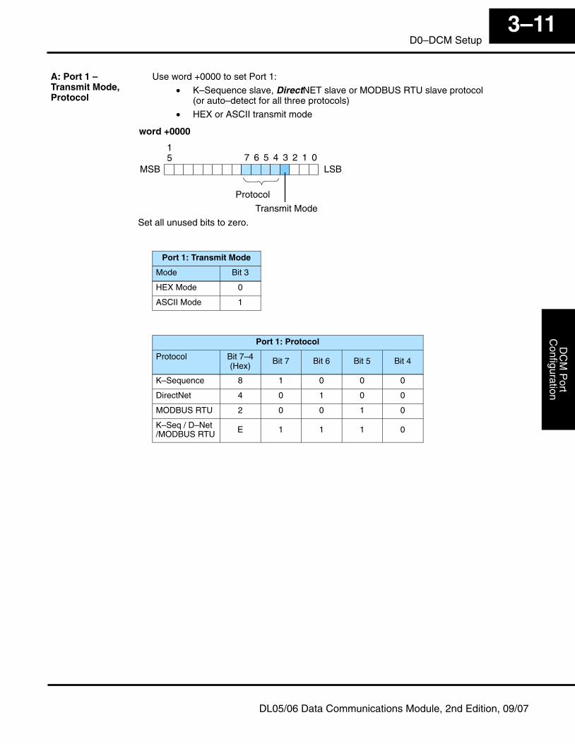
Use word +0000 to set Port 1:
• K–Sequence slave, DirectNET slave or MODBUS RTU slave protocol(or auto–detect for all three protocols)
• HEX or ASCII transmit mode
MSB LSB07 6 5 4 3 2 1
Transmit Mode
Protocol
word +0000
15
Set all unused bits to zero.
Port 1: Transmit Mode
Mode Bit 3
HEX Mode 0
ASCII Mode 1
Port 1: Protocol
Protocol Bit 7–4(Hex)
Bit 7 Bit 6 Bit 5 Bit 4
K–Sequence 8 1 0 0 0
DirectNet 4 0 1 0 0
MODBUS RTU 2 0 0 1 0
K–Seq / D–Net/MODBUS RTU E 1 1 1 0
A: Port 1 – Transmit Mode,Protocol
DC
M P
ort
Con
figur
atio
nIn
stal
latio
n an
dS
afet
y G
uide
lines
3–12D0–DCM Setup
DL05/06 Data Communications Module, 2nd Edition, 09/07
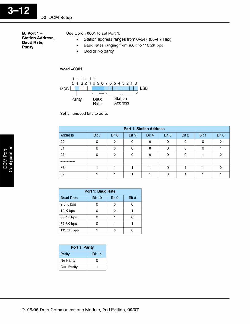
Use word +0001 to set Port 1:
• Station address ranges from 0–247 (00–F7 Hex)
• Baud rates ranging from 9.6K to 115.2K bps
• Odd or No parity
MSB LSB0
11
10 9 8 7 6 5 4 3 2 1
BaudRate
StationAddress
15
14
13
12
Parity
word +0001
Set all unused bits to zero.
Port 1: Station Address
Address Bit 7 Bit 6 Bit 5 Bit 4 Bit 3 Bit 2 Bit 1 Bit 0
00 0 0 0 0 0 0 0 0
01 0 0 0 0 0 0 0 1
02 0 0 0 0 0 0 1 0
– – – – –
F6 1 1 1 1 0 1 1 0
F7 1 1 1 1 0 1 1 1
Port 1: Baud Rate
Baud Rate Bit 10 Bit 9 Bit 8
9.6 K bps 0 0 0
19.K bps 0 0 1
38.4K bps 0 1 0
57.6K bps 0 1 1
115.2K bps 1 0 0
Port 1: Parity
Parity Bit 14
No Parity 0
Odd Parity 1
B: Port 1 – Station Address,Baud Rate, Parity
DC
M P
ortC
onfigurationInstallation and
Safety G
uidelines3–13
D0–DCM Setup
DL05/06 Data Communications Module, 2nd Edition, 09/07
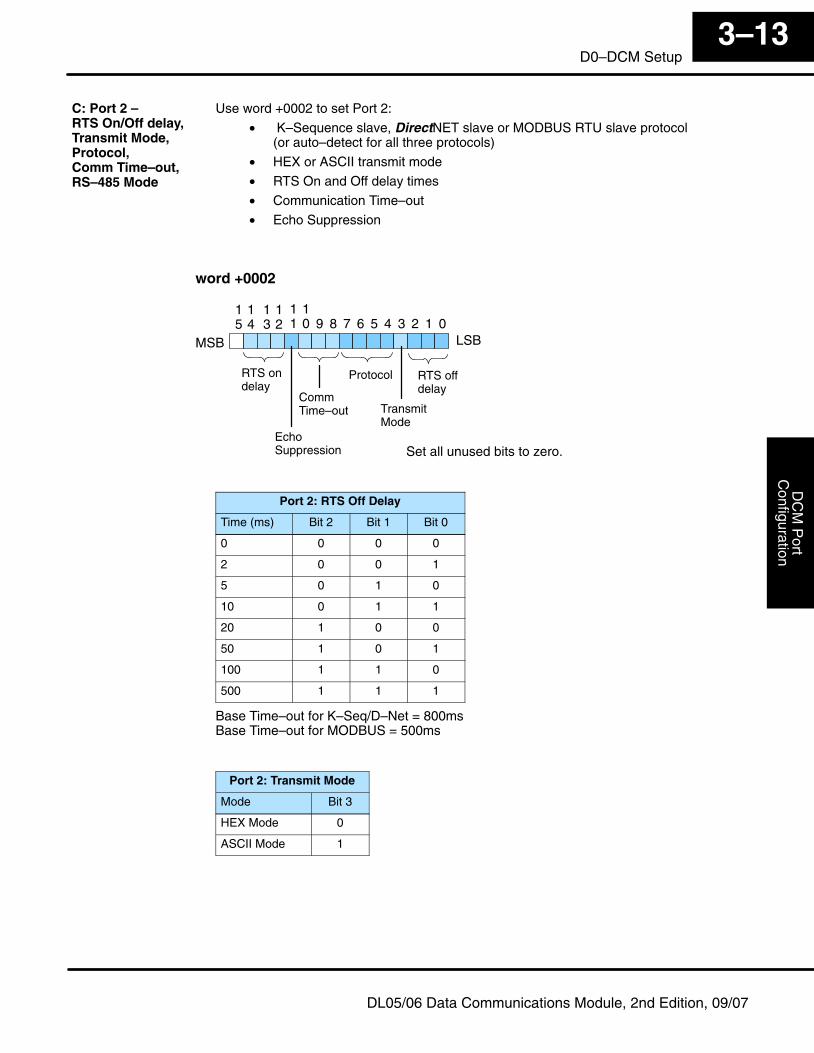
Use word +0002 to set Port 2:
• K–Sequence slave, DirectNET slave or MODBUS RTU slave protocol(or auto–detect for all three protocols)
• HEX or ASCII transmit mode
• RTS On and Off delay times
• Communication Time–out
• Echo Suppression
MSB LSB0
11
10 9 8 7 6 5 4 3 2 1
Protocol RTS offdelay
15
14
13
12
word +0002
TransmitMode
CommTime–out
EchoSuppression
RTS ondelay
Set all unused bits to zero.
Port 2: RTS Off Delay
Time (ms) Bit 2 Bit 1 Bit 0
0 0 0 0
2 0 0 1
5 0 1 0
10 0 1 1
20 1 0 0
50 1 0 1
100 1 1 0
500 1 1 1
Base Time–out for K–Seq/D–Net = 800msBase Time–out for MODBUS = 500ms
Port 2: Transmit Mode
Mode Bit 3
HEX Mode 0
ASCII Mode 1
C: Port 2 – RTS On/Off delay,Transmit Mode,Protocol, Comm Time–out, RS–485 Mode
DC
M P
ort
Con
figur
atio
nIn
stal
latio
n an
dS
afet
y G
uide
lines
3–14D0–DCM Setup
DL05/06 Data Communications Module, 2nd Edition, 09/07
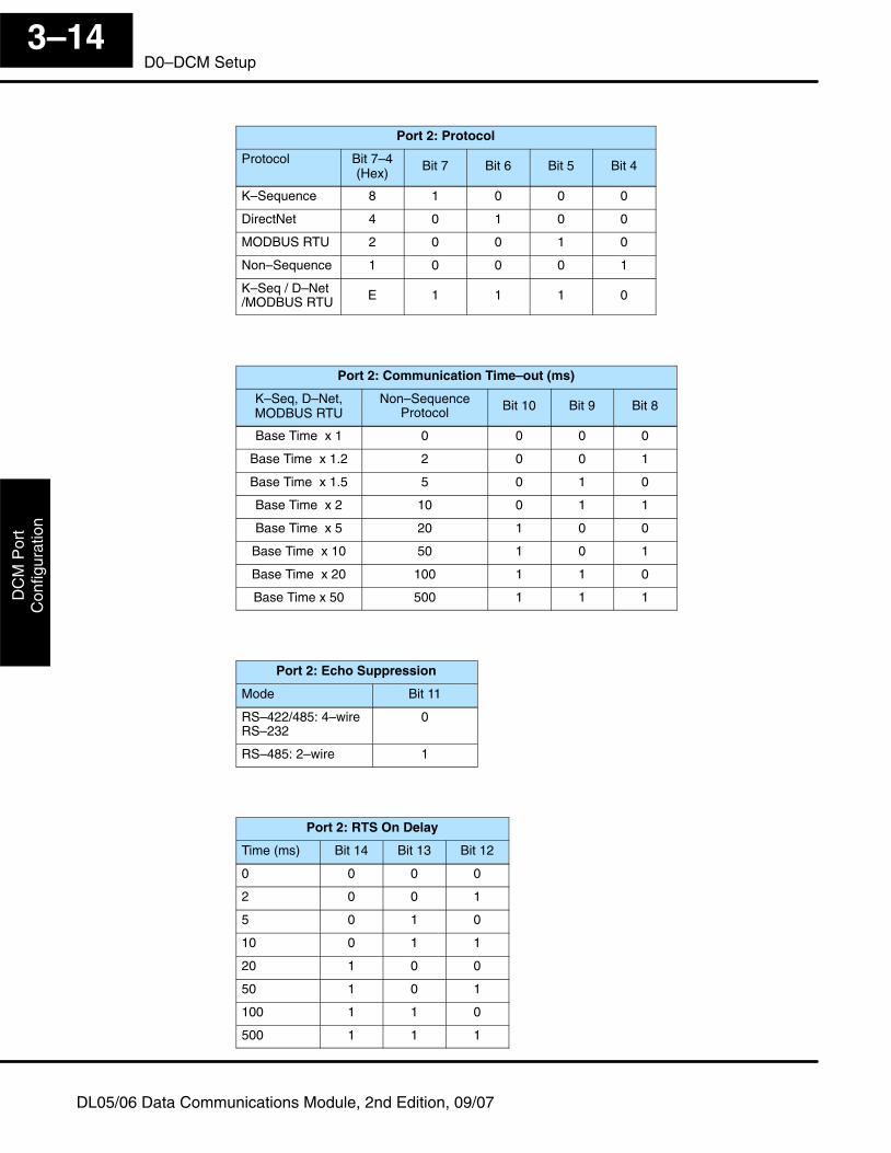
Port 2: Protocol
Protocol Bit 7–4(Hex)
Bit 7 Bit 6 Bit 5 Bit 4
K–Sequence 8 1 0 0 0
DirectNet 4 0 1 0 0
MODBUS RTU 2 0 0 1 0
Non–Sequence 1 0 0 0 1
K–Seq / D–Net/MODBUS RTU E 1 1 1 0
Port 2: Communication Time–out (ms)
K–Seq, D–Net,MODBUS RTU
Non–SequenceProtocol Bit 10 Bit 9 Bit 8
Base Time x 1 0 0 0 0
Base Time x 1.2 2 0 0 1
Base Time x 1.5 5 0 1 0
Base Time x 2 10 0 1 1
Base Time x 5 20 1 0 0
Base Time x 10 50 1 0 1
Base Time x 20 100 1 1 0
Base Time x 50 500 1 1 1
Port 2: Echo Suppression
Mode Bit 11
RS–422/485: 4–wireRS–232
0
RS–485: 2–wire 1
Port 2: RTS On Delay
Time (ms) Bit 14 Bit 13 Bit 12
0 0 0 0
2 0 0 1
5 0 1 0
10 0 1 1
20 1 0 0
50 1 0 1
100 1 1 0
500 1 1 1
DC
M P
ortC
onfigurationInstallation and
Safety G
uidelines3–15
D0–DCM Setup
DL05/06 Data Communications Module, 2nd Edition, 09/07
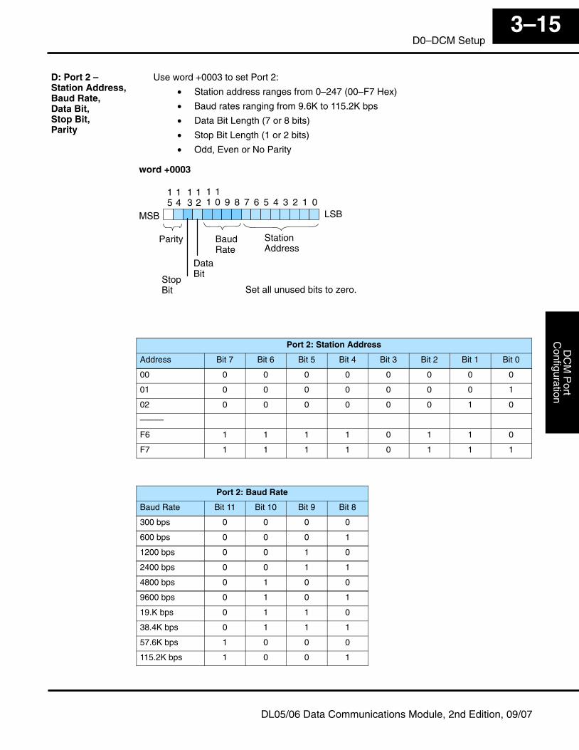
Use word +0003 to set Port 2:
• Station address ranges from 0–247 (00–F7 Hex)
• Baud rates ranging from 9.6K to 115.2K bps
• Data Bit Length (7 or 8 bits)
• Stop Bit Length (1 or 2 bits)
• Odd, Even or No Parity
MSB LSB0
11
10 9 8 7 6 5 4 3 2 1
BaudRate
StationAddress
15
14
13
12
Parity
word +0003
DataBit
StopBit Set all unused bits to zero.
Port 2: Station Address
Address Bit 7 Bit 6 Bit 5 Bit 4 Bit 3 Bit 2 Bit 1 Bit 0
00 0 0 0 0 0 0 0 0
01 0 0 0 0 0 0 0 1
02 0 0 0 0 0 0 1 0
–––––
F6 1 1 1 1 0 1 1 0
F7 1 1 1 1 0 1 1 1
Port 2: Baud Rate
Baud Rate Bit 11 Bit 10 Bit 9 Bit 8
300 bps 0 0 0 0
600 bps 0 0 0 1
1200 bps 0 0 1 0
2400 bps 0 0 1 1
4800 bps 0 1 0 0
9600 bps 0 1 0 1
19.K bps 0 1 1 0
38.4K bps 0 1 1 1
57.6K bps 1 0 0 0
115.2K bps 1 0 0 1
D: Port 2 – Station Address,Baud Rate, Data Bit,Stop Bit,Parity
DC
M P
ort
Con
figur
atio
nIn
stal
latio
n an
dS
afet
y G
uide
lines
3–16D0–DCM Setup
DL05/06 Data Communications Module, 2nd Edition, 09/07
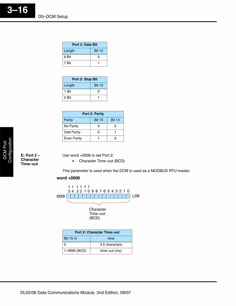
Port 2: Data Bit
Length Bit 12
8 Bit 0
7 Bit 1
Port 2: Stop Bit
Length Bit 13
1 Bit 0
2 Bit 1
Port 2: Parity
Parity Bit 15 Bit 14
No Parity 0 0
Odd Parity 0 1
Even Parity 1 0
Use word +0006 to set Port 2:
• Character Time–out (BCD)
This parameter is used when the DCM is used as a MODBUS RTU master.
MSB LSB0
11
10 9 8 7 6 5 4 3 2 1
CharacterTime–out(BCD)
15
14
13
12
word +0006
Port 2: Character Time–out
Bit 15–0 time
0 3.5 characters
1–9999 (BCD) time–out (ms)
E: Port 2 – CharacterTime–out
DC
M P
ortC
onfigurationInstallation and
Safety G
uidelines3–17
D0–DCM Setup
DL05/06 Data Communications Module, 2nd Edition, 09/07
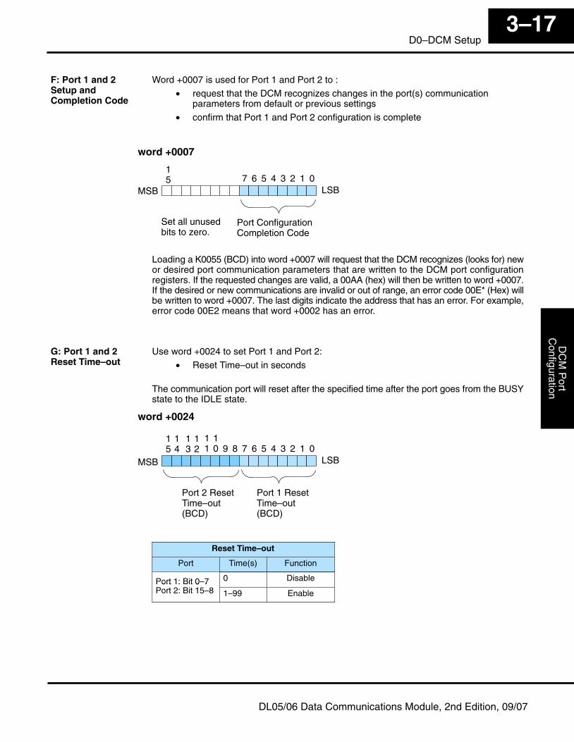
Word +0007 is used for Port 1 and Port 2 to :
• request that the DCM recognizes changes in the port(s) communicationparameters from default or previous settings
• confirm that Port 1 and Port 2 configuration is complete
MSB LSB07 6 5 4 3 2 1
Port ConfigurationCompletion Code
word +0007
15
Set all unusedbits to zero.
Loading a K0055 (BCD) into word +0007 will request that the DCM recognizes (looks for) newor desired port communication parameters that are written to the DCM port configurationregisters. If the requested changes are valid, a 00AA (hex) will then be written to word +0007.If the desired or new communications are invalid or out of range, an error code 00E* (Hex) willbe written to word +0007. The last digits indicate the address that has an error. For example,error code 00E2 means that word +0002 has an error.
Use word +0024 to set Port 1 and Port 2:
• Reset Time–out in seconds
The communication port will reset after the specified time after the port goes from the BUSYstate to the IDLE state.
MSB LSB0
11
10 9 8 7 6 5 4 3 2 1
Port 2 ResetTime–out(BCD)
15
14
13
12
word +0024
Port 1 ResetTime–out(BCD)
Reset Time–out
Port Time(s) Function
Port 1: Bit 0–7 0 DisablePort 1: Bit 0 7Port 2: Bit 15–8 1–99 Enable
F: Port 1 and 2Setup andCompletion Code
G: Port 1 and 2Reset Time–out
DC
M P
ort
Con
figur
atio
nIn
stal
latio
n an
dS
afet
y G
uide
lines
3–18D0–DCM Setup
DL05/06 Data Communications Module, 2nd Edition, 09/07
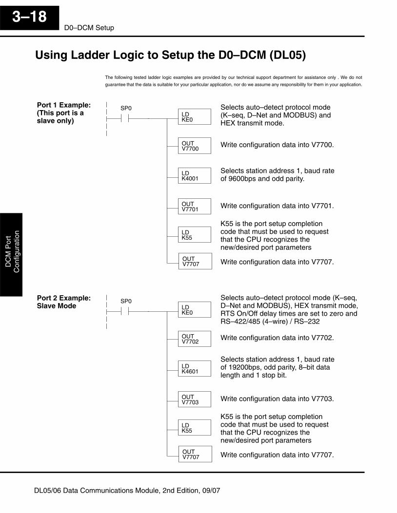
Using Ladder Logic to Setup the D0–DCM (DL05)
The following tested ladder logic examples are provided by our technical support department for assistance only . We do not
guarantee that the data is suitable for your particular application, nor do we assume any responsibility for them in your application.
LDKE0
LDK4001
OUTV7701
LDK55
SP0 Selects auto–detect protocol mode(K–seq, D–Net and MODBUS) andHEX transmit mode.
Write configuration data into V7700.OUTV7700
OUTV7707
Selects station address 1, baud rateof 9600bps and odd parity.
Write configuration data into V7701.
Write configuration data into V7707.
K55 is the port setup completioncode that must be used to requestthat the CPU recognizes thenew/desired port parameters
LDKE0
LDK4601
OUTV7703
LDK55
SP0 Selects auto–detect protocol mode (K–seq,D–Net and MODBUS), HEX transmit mode,RTS On/Off delay times are set to zero andRS–422/485 (4–wire) / RS–232
Write configuration data into V7702.OUTV7702
OUTV7707
Selects station address 1, baud rateof 19200bps, odd parity, 8–bit datalength and 1 stop bit.
Write configuration data into V7703.
Write configuration data into V7707.
K55 is the port setup completioncode that must be used to requestthat the CPU recognizes thenew/desired port parameters
Port 1 Example:(This port is aslave only)
Port 2 Example:Slave Mode
DC
M P
ortC
onfigurationInstallation and
Safety G
uidelines3–19
D0–DCM Setup
DL05/06 Data Communications Module, 2nd Edition, 09/07
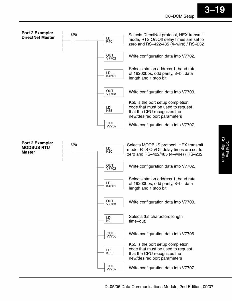
LDK40
LDK4601
OUTV7703
LDK55
SP0 Selects DirectNet protocol, HEX transmitmode, RTS On/Off delay times are set tozero and RS–422/485 (4–wire) / RS–232
Write configuration data into V7702.OUTV7702
OUTV7707
Selects station address 1, baud rateof 19200bps, odd parity, 8–bit datalength and 1 stop bit.
Write configuration data into V7703.
Write configuration data into V7707.
K55 is the port setup completioncode that must be used to requestthat the CPU recognizes thenew/desired port parameters
LDK20
LDK4601
OUTV7703
LDK0
SP0 Selects MODBUS protocol, HEX transmitmode, RTS On/Off delay times are set tozero and RS–422/485 (4–wire) / RS–232
Write configuration data into V7702.OUTV7702
OUTV7706
Selects station address 1, baud rateof 19200bps, odd parity, 8–bit datalength and 1 stop bit.
Write configuration data into V7703.
Write configuration data into V7707.
K55 is the port setup completioncode that must be used to requestthat the CPU recognizes thenew/desired port parameters
LDK55
OUTV7707
Selects 3.5 characters lengthtime–out.
Write configuration data into V7706.
Port 2 Example:DirectNet Master
Port 2 Example:MODBUS RTUMaster
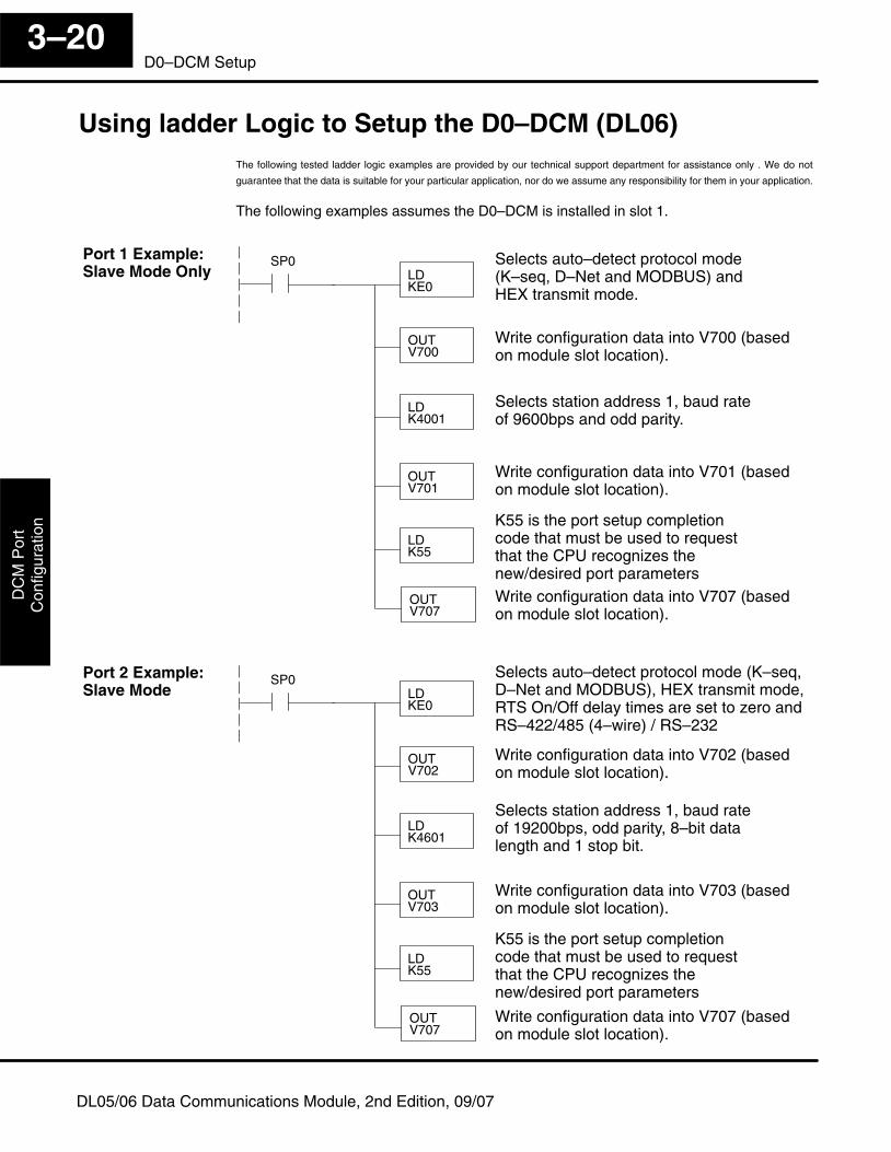
DC
M P
ort
Con
figur
atio
nIn
stal
latio
n an
dS
afet
y G
uide
lines
3–20D0–DCM Setup
DL05/06 Data Communications Module, 2nd Edition, 09/07
Using ladder Logic to Setup the D0–DCM (DL06)The following tested ladder logic examples are provided by our technical support department for assistance only . We do not
guarantee that the data is suitable for your particular application, nor do we assume any responsibility for them in your application.
The following examples assumes the D0–DCM is installed in slot 1.
LDKE0
LDK4001
OUTV701
LDK55
SP0 Selects auto–detect protocol mode(K–seq, D–Net and MODBUS) andHEX transmit mode.
Write configuration data into V700 (basedon module slot location).
OUTV700
OUTV707
Selects station address 1, baud rateof 9600bps and odd parity.
Write configuration data into V701 (basedon module slot location).
Write configuration data into V707 (basedon module slot location).
K55 is the port setup completioncode that must be used to requestthat the CPU recognizes thenew/desired port parameters
LDKE0
LDK4601
OUTV703
LDK55
SP0 Selects auto–detect protocol mode (K–seq,D–Net and MODBUS), HEX transmit mode,RTS On/Off delay times are set to zero andRS–422/485 (4–wire) / RS–232
Write configuration data into V702 (basedon module slot location).
OUTV702
OUTV707
Selects station address 1, baud rateof 19200bps, odd parity, 8–bit datalength and 1 stop bit.
Write configuration data into V703 (basedon module slot location).
Write configuration data into V707 (basedon module slot location).
K55 is the port setup completioncode that must be used to requestthat the CPU recognizes thenew/desired port parameters
Port 1 Example:Slave Mode Only
Port 2 Example:Slave Mode
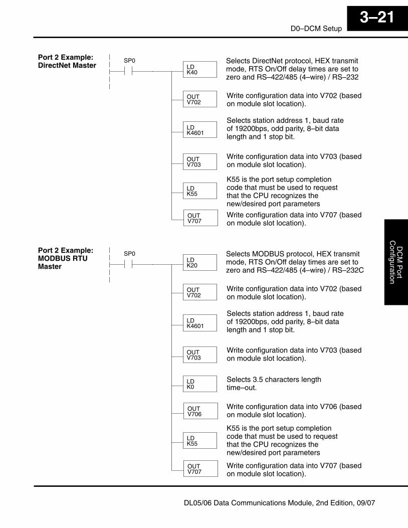
DC
M P
ortC
onfigurationInstallation and
Safety G
uidelines3–21
D0–DCM Setup
DL05/06 Data Communications Module, 2nd Edition, 09/07
LDK40
LDK4601
OUTV703
LDK55
SP0 Selects DirectNet protocol, HEX transmitmode, RTS On/Off delay times are set tozero and RS–422/485 (4–wire) / RS–232
Write configuration data into V702 (basedon module slot location).
OUTV702
OUTV707
Selects station address 1, baud rateof 19200bps, odd parity, 8–bit datalength and 1 stop bit.
Write configuration data into V703 (basedon module slot location).
Write configuration data into V707 (basedon module slot location).
K55 is the port setup completioncode that must be used to requestthat the CPU recognizes thenew/desired port parameters
LDK20
LDK4601
OUTV703
LDK0
SP0 Selects MODBUS protocol, HEX transmitmode, RTS On/Off delay times are set tozero and RS–422/485 (4–wire) / RS–232C
Write configuration data into V702 (basedon module slot location).
OUTV702
OUTV706
Selects station address 1, baud rateof 19200bps, odd parity, 8–bit datalength and 1 stop bit.
Write configuration data into V703 (basedon module slot location).
Write configuration data into V707 (basedon module slot location).
K55 is the port setup completioncode that must be used to requestthat the CPU recognizes thenew/desired port parameters
LDK55
OUTV707
Selects 3.5 characters lengthtime–out.
Write configuration data into V706 (basedon module slot location).
Port 2 Example:DirectNet Master
Port 2 Example:MODBUS RTUMaster
14DirectNetCommunicationsUsing RX/WX
In This Chapter. . . .— RX / WX Network Instructions— Addressing the Different Memory Types— Special Relays for Communications— Example Program with One RX Instruction— Example Program with One WX Instruction— Integrating Multiple RX and WX Instructions
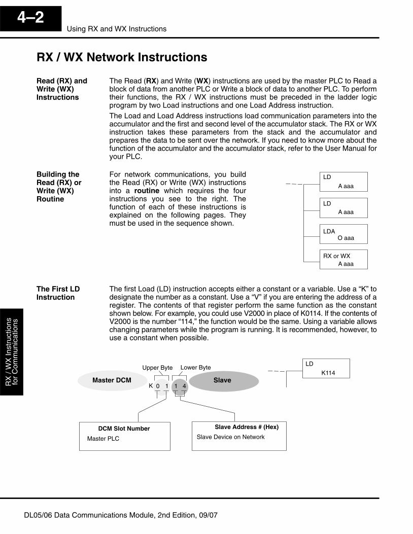
Get
ting
Sta
rted
Use
r App
licat
ion
Gui
delin
esR
X /
WX
Inst
ruct
ions
for
Com
mun
icat
ions
4–2Using RX and WX Instructions
DL05/06 Data Communications Module, 2nd Edition, 09/07
RX / WX Network Instructions
The Read (RX) and Write (WX) instructions are used by the master PLC to Read ablock of data from another PLC or Write a block of data to another PLC. To performtheir functions, the RX / WX instructions must be preceded in the ladder logicprogram by two Load instructions and one Load Address instruction.The Load and Load Address instructions load communication parameters into theaccumulator and the first and second level of the accumulator stack. The RX or WXinstruction takes these parameters from the stack and the accumulator andprepares the data to be sent over the network. If you need to know more about thefunction of the accumulator and the accumulator stack, refer to the User Manual foryour PLC.
For network communications, you buildthe Read (RX) or Write (WX) instructionsinto a routine which requires the fourinstructions you see to the right. Thefunction of each of these instructions isexplained on the following pages. Theymust be used in the sequence shown.
LDAO aaa
LDA aaa
LD
A aaa
RX or WXA aaa
The first Load (LD) instruction accepts either a constant or a variable. Use a “K” todesignate the number as a constant. Use a “V” if you are entering the address of aregister. The contents of that register perform the same function as the constantshown below. For example, you could use V2000 in place of K0114. If the contents ofV2000 is the number “114,” the function would be the same. Using a variable allowschanging parameters while the program is running. It is recommended, however, touse a constant when possible.
LD
K114
1 1 40K
Upper Byte Lower Byte
SlaveMaster DCM
Slave Address # (Hex)
Slave Device on NetworkDCM Slot Number
Master PLC
Read (RX) andWrite (WX)Instructions
Building the Read (RX) orWrite (WX) Routine
The First LDInstruction
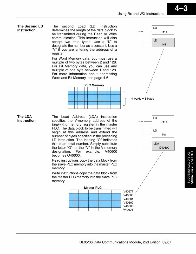
User A
pplicationG
uidelinesR
X / W
X Instructions
for Com
munications
4–3Using Rx and WX Instructions
DL05/06 Data Communications Module, 2nd Edition, 09/07
The second Load (LD) instructiondetermines the length of the data block tobe transmitted during the Read or Writecommunication. This instruction will alsoaccept two data types. Use a “K” todesignate the number as a constant. Use a“V” if you are entering the address of aregister.For Word Memory data, you must use amultiple of two bytes between 2 and 128.For Bit Memory data, you can use anymultiple of one byte between 1 and 128.For more information about addressingWord and Bit Memory, see page 4-6.
LDK8
LD
K114
PLC Memory
4 words = 8 bytes
LDK8
LD
K114
LDAO40600
The Load Address (LDA) instructionspecifies the V-memory address of thebeginning memory register in the masterPLC. The data block to be transmitted willbegin at this address and extend thenumber of bytes specified in the precedingLD instruction. The leading “O” indicatesthis is an octal number. Simply substitutethe letter “O” for the “V” in the V-memorydesignation. For example, V40600becomes O40600.Read instructions copy the data block fromthe slave PLC memory into the master PLCmemory.Write instructions copy the data block fromthe master PLC memory into the slave PLCmemory.
V40600V40601V40602V40603
V40577
V40604
Master PLC
The Second LDInstruction
The LDAInstruction
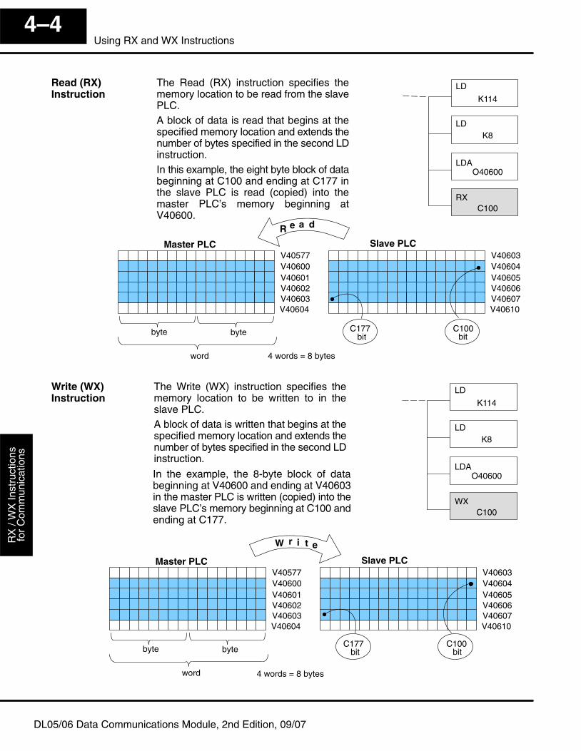
Get
ting
Sta
rted
Use
r App
licat
ion
Gui
delin
esR
X /
WX
Inst
ruct
ions
for
Com
mun
icat
ions
4–4Using RX and WX Instructions
DL05/06 Data Communications Module, 2nd Edition, 09/07
V40600V40601V40602V40603
V40577
V40604
Master PLC
V40604V40605V40606V40607
V40603
V40610
Slave PLC
R e a d
bytebyte
word 4 words = 8 bytes
The Read (RX) instruction specifies thememory location to be read from the slavePLC.A block of data is read that begins at thespecified memory location and extends thenumber of bytes specified in the second LDinstruction.In this example, the eight byte block of databeginning at C100 and ending at C177 inthe slave PLC is read (copied) into themaster PLC’s memory beginning atV40600.
LDAO40600
LDK8
LD
K114
RXC100
C100C177bitbit
The Write (WX) instruction specifies thememory location to be written to in theslave PLC.A block of data is written that begins at thespecified memory location and extends thenumber of bytes specified in the second LDinstruction.
LDAO40600
LDK8
LD
K114
WXC100
In the example, the 8-byte block of databeginning at V40600 and ending at V40603in the master PLC is written (copied) into theslave PLC’s memory beginning at C100 andending at C177.
V40600V40601V40602V40603
V40577
V40604
Master PLC
V40604V40605V40606V40607
V40603
V40610
Slave PLC
W r i t e
bytebyte
word 4 words = 8 bytes
C100C177bitbit
Read (RX)Instruction
Write (WX)Instruction
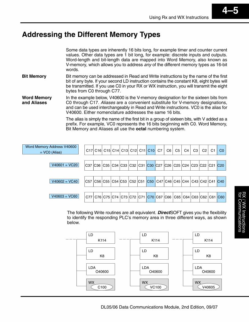
User A
pplicationG
uidelinesR
X / W
X Instructions
for Com
munications
4–5Using Rx and WX Instructions
DL05/06 Data Communications Module, 2nd Edition, 09/07
Addressing the Different Memory Types
Some data types are inherently 16 bits long, for example timer and counter currentvalues. Other data types are 1 bit long, for example: discrete inputs and outputs.Word-length and bit-length data are mapped into Word Memory, also known asV-memory, which allows you to address any of the different memory types as 16-bitwords.
Bit memory can be addressed in Read and Write instructions by the name of the firstbit of any byte. If your second LD instruction contains the constant K8, eight bytes willbe transmitted. If you use C0 in your RX or WX instruction, you will transmit the eightbytes from C0 through C77.
In the example below, V40600 is the V-memory designation for the sixteen bits fromC0 through C17. Aliases are a convenient substitute for V-memory designations,and can be used interchangeably in Read and Write instructions. VC0 is the alias forV40600. Either nomenclature addresses the same 16 bits.
The alias is simply the name of the first bit in a group of sixteen bits, with V added as aprefix. For example, VC0 represents the 16 bits beginning with C0. Word Memory,Bit Memory and Aliases all use the octal numbering system.
C1C2C3C4C5C6C7C10C11C12C13C14C15C16C17 C0Word Memory Address V40600
= VC0 (Alias)
V40601 = VC20
V40602 = VC40
V40603 = VC60 C74 C73 C72 C71 C70 C67 C66 C65 C64 C63 C62 C61 C60C75C76C77
C57 C56 C55 C54 C53 C52 C51 C50 C47 C46 C45 C44 C43 C42 C41 C40
C37 C36 C35 C34 C33 C32 C31 C30 C27 C26 C25 C24 C23 C22 C21 C20
LDAO40600
LDK8
LD
K114
WX
LDAO40600
LDK8
LD
K114
WXVC100
LDAO40600
LDK8
LD
K114
WXC100
The following Write routines are all equivalent. DirectSOFT gives you the flexibilityto identify the responding PLC’s memory area in three different ways, as shownbelow.
V40605
Bit Memory
Word Memory and Aliases
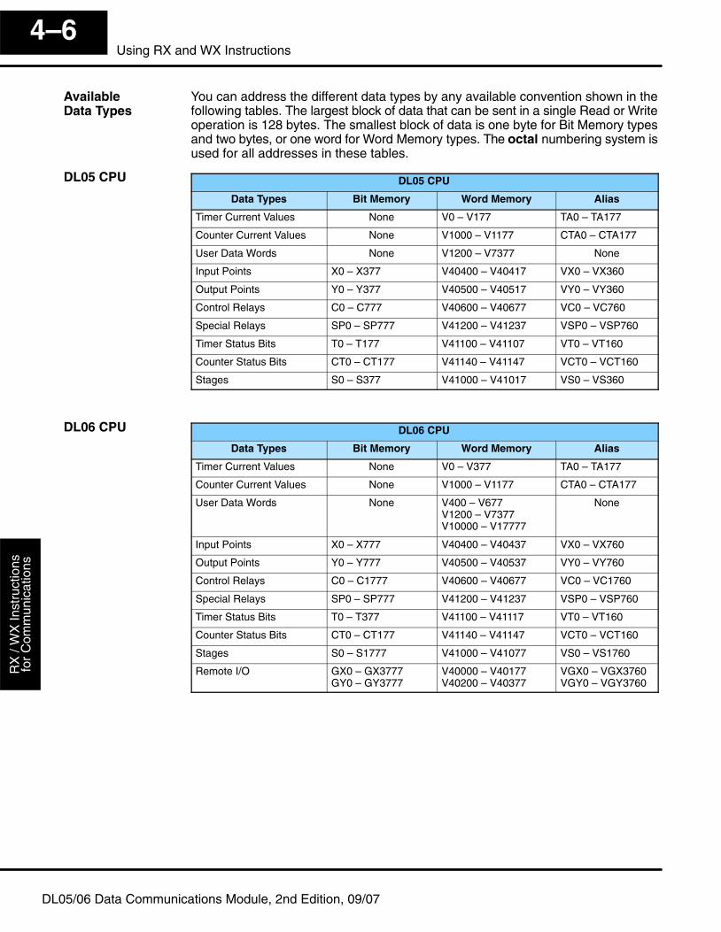
Get
ting
Sta
rted
Use
r App
licat
ion
Gui
delin
esR
X /
WX
Inst
ruct
ions
for
Com
mun
icat
ions
4–6Using RX and WX Instructions
DL05/06 Data Communications Module, 2nd Edition, 09/07
You can address the different data types by any available convention shown in thefollowing tables. The largest block of data that can be sent in a single Read or Writeoperation is 128 bytes. The smallest block of data is one byte for Bit Memory typesand two bytes, or one word for Word Memory types. The octal numbering system isused for all addresses in these tables.
DL05 CPU
Data Types Bit Memory Word Memory Alias
Timer Current Values None V0 – V177 TA0 – TA177
Counter Current Values None V1000 – V1177 CTA0 – CTA177
User Data Words None V1200 – V7377 None
Input Points X0 – X377 V40400 – V40417 VX0 – VX360
Output Points Y0 – Y377 V40500 – V40517 VY0 – VY360
Control Relays C0 – C777 V40600 – V40677 VC0 – VC760
Special Relays SP0 – SP777 V41200 – V41237 VSP0 – VSP760
Timer Status Bits T0 – T177 V41100 – V41107 VT0 – VT160
Counter Status Bits CT0 – CT177 V41140 – V41147 VCT0 – VCT160
Stages S0 – S377 V41000 – V41017 VS0 – VS360
DL06 CPU
Data Types Bit Memory Word Memory Alias
Timer Current Values None V0 – V377 TA0 – TA177
Counter Current Values None V1000 – V1177 CTA0 – CTA177
User Data Words None V400 – V677V1200 – V7377V10000 – V17777
None
Input Points X0 – X777 V40400 – V40437 VX0 – VX760
Output Points Y0 – Y777 V40500 – V40537 VY0 – VY760
Control Relays C0 – C1777 V40600 – V40677 VC0 – VC1760
Special Relays SP0 – SP777 V41200 – V41237 VSP0 – VSP760
Timer Status Bits T0 – T377 V41100 – V41117 VT0 – VT160
Counter Status Bits CT0 – CT177 V41140 – V41147 VCT0 – VCT160
Stages S0 – S1777 V41000 – V41077 VS0 – VS1760
Remote I/O GX0 – GX3777GY0 – GY3777
V40000 – V40177V40200 – V40377
VGX0 – VGX3760VGY0 – VGY3760
DL05 CPU
Available Data Types
DL06 CPU
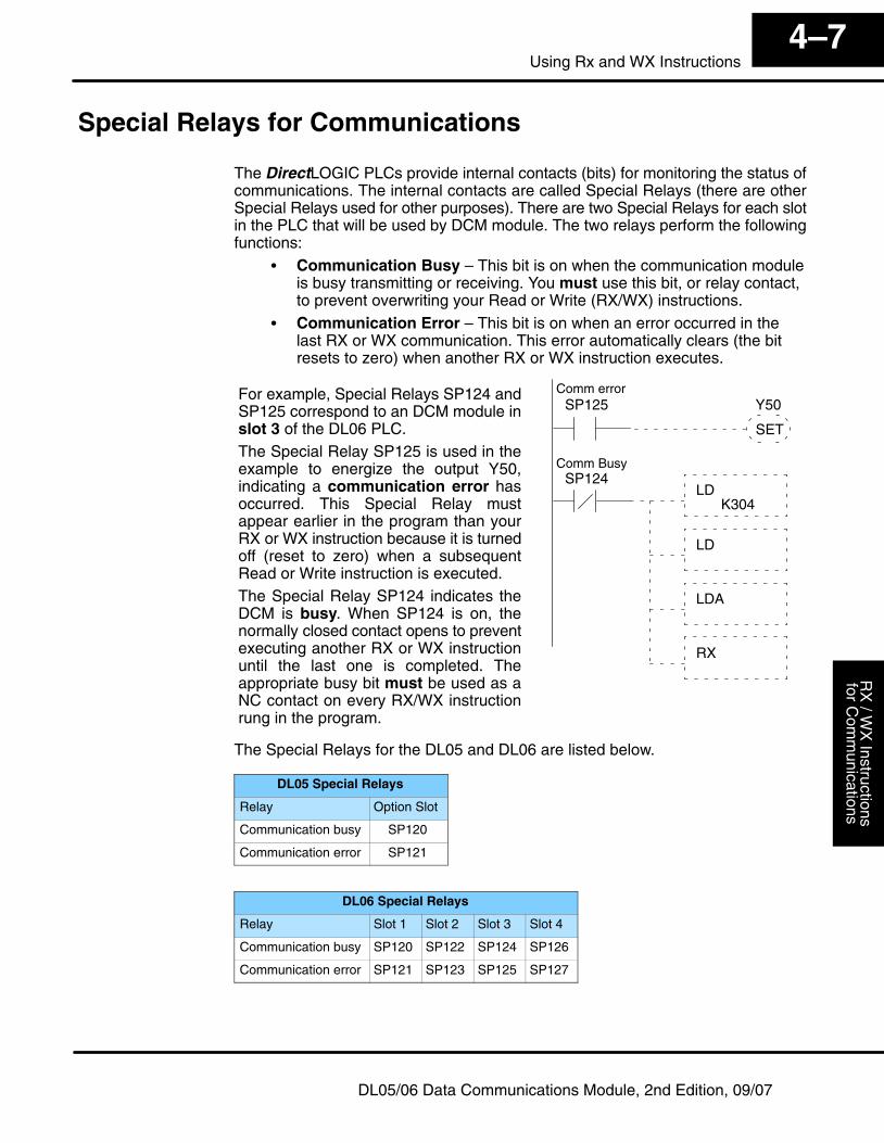
User A
pplicationG
uidelinesR
X / W
X Instructions
for Com
munications
4–7Using Rx and WX Instructions
DL05/06 Data Communications Module, 2nd Edition, 09/07
Special Relays for Communications
The DirectLOGIC PLCs provide internal contacts (bits) for monitoring the status ofcommunications. The internal contacts are called Special Relays (there are otherSpecial Relays used for other purposes). There are two Special Relays for each slotin the PLC that will be used by DCM module. The two relays perform the followingfunctions:
� Communication Busy – This bit is on when the communication moduleis busy transmitting or receiving. You must use this bit, or relay contact,to prevent overwriting your Read or Write (RX/WX) instructions.
� Communication Error – This bit is on when an error occurred in thelast RX or WX communication. This error automatically clears (the bitresets to zero) when another RX or WX instruction executes.
Y50SP125
SP124LD
LD
LDA
RX
For example, Special Relays SP124 andSP125 correspond to an DCM module inslot 3 of the DL06 PLC.The Special Relay SP125 is used in theexample to energize the output Y50,indicating a communication error hasoccurred. This Special Relay mustappear earlier in the program than yourRX or WX instruction because it is turnedoff (reset to zero) when a subsequentRead or Write instruction is executed.The Special Relay SP124 indicates theDCM is busy. When SP124 is on, thenormally closed contact opens to preventexecuting another RX or WX instructionuntil the last one is completed. Theappropriate busy bit must be used as aNC contact on every RX/WX instructionrung in the program.
SET
K304
Comm Busy
Comm error
The Special Relays for the DL05 and DL06 are listed below.
DL05 Special Relays
Relay Option Slot
Communication busy SP120
Communication error SP121
DL06 Special Relays
Relay Slot 1 Slot 2 Slot 3 Slot 4
Communication busy SP120 SP122 SP124 SP126
Communication error SP121 SP123 SP125 SP127
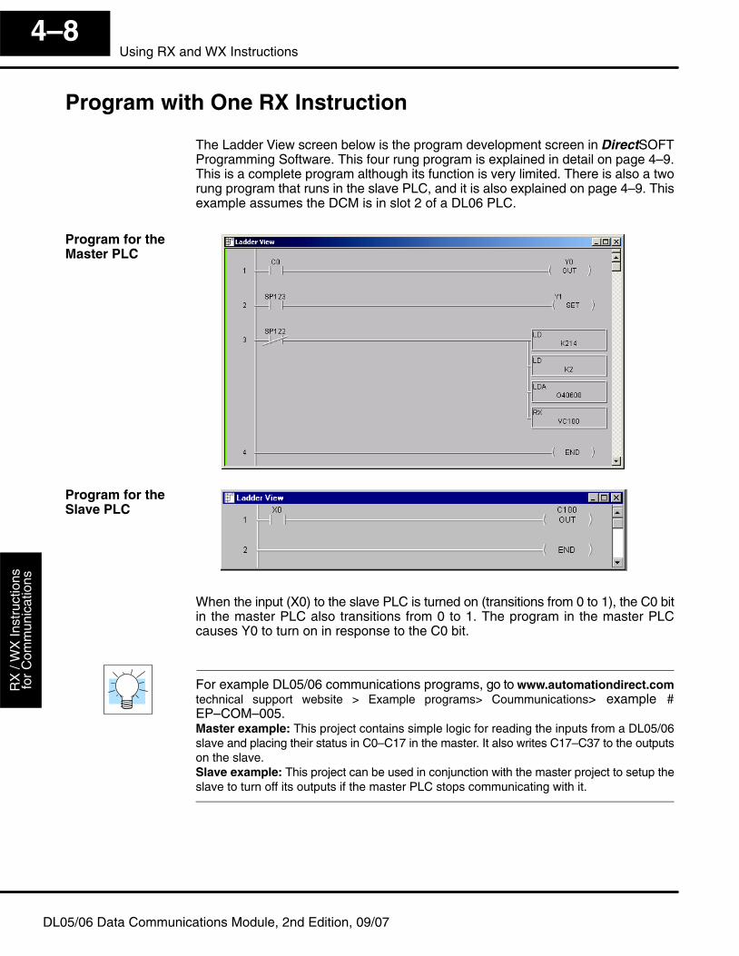
Get
ting
Sta
rted
Use
r App
licat
ion
Gui
delin
esR
X /
WX
Inst
ruct
ions
for
Com
mun
icat
ions
4–8Using RX and WX Instructions
DL05/06 Data Communications Module, 2nd Edition, 09/07
Program with One RX Instruction
The Ladder View screen below is the program development screen in DirectSOFTProgramming Software. This four rung program is explained in detail on page 4–9.This is a complete program although its function is very limited. There is also a tworung program that runs in the slave PLC, and it is also explained on page 4–9. Thisexample assumes the DCM is in slot 2 of a DL06 PLC.
When the input (X0) to the slave PLC is turned on (transitions from 0 to 1), the C0 bitin the master PLC also transitions from 0 to 1. The program in the master PLCcauses Y0 to turn on in response to the C0 bit.
For example DL05/06 communications programs, go to www.automationdirect.comtechnical support website > Example programs> Coummunications> example #EP–COM–005. Master example: This project contains simple logic for reading the inputs from a DL05/06slave and placing their status in C0–C17 in the master. It also writes C17–C37 to the outputson the slave.Slave example: This project can be used in conjunction with the master project to setup theslave to turn off its outputs if the master PLC stops communicating with it.
Program for theMaster PLC
Program for theSlave PLC
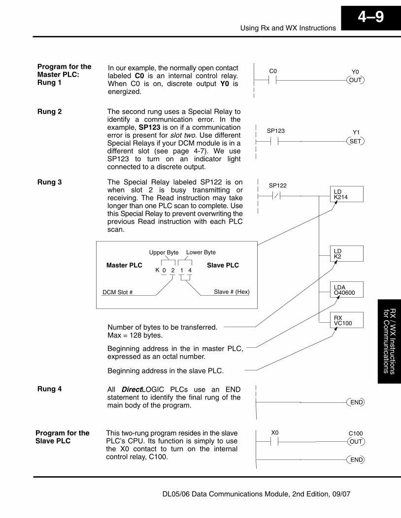
User A
pplicationG
uidelinesR
X / W
X Instructions
for Com
munications
4–9Using Rx and WX Instructions
DL05/06 Data Communications Module, 2nd Edition, 09/07
OUTY0C0In our example, the normally open contact
labeled C0 is an internal control relay.When C0 is on, discrete output Y0 isenergized.
SET
SP123 Y1
The second rung uses a Special Relay toidentify a communication error. In theexample, SP123 is on if a communicationerror is present for slot two. Use differentSpecial Relays if your DCM module is in adifferent slot (see page 4-7). We useSP123 to turn on an indicator lightconnected to a discrete output.
LDK214
LDK2
LDAO40600
RXVC100
SP122The Special Relay labeled SP122 is onwhen slot 2 is busy transmitting orreceiving. The Read instruction may takelonger than one PLC scan to complete. Usethis Special Relay to prevent overwriting theprevious Read instruction with each PLCscan.
Number of bytes to be transferred.Max = 128 bytes.
Beginning address in the in master PLC,expressed as an octal number.
Beginning address in the slave PLC.
2 1 40
Slave # (Hex)
K
Upper Byte Lower Byte
Slave PLCMaster PLC
DCM Slot #
END
All DirectLOGIC PLCs use an ENDstatement to identify the final rung of themain body of the program.
END
OUTC100X0This two-rung program resides in the slave
PLC’s CPU. Its function is simply to usethe X0 contact to turn on the internalcontrol relay, C100.
Program for theMaster PLC: Rung 1
Rung 2
Rung 3
Rung 4
Program for theSlave PLC
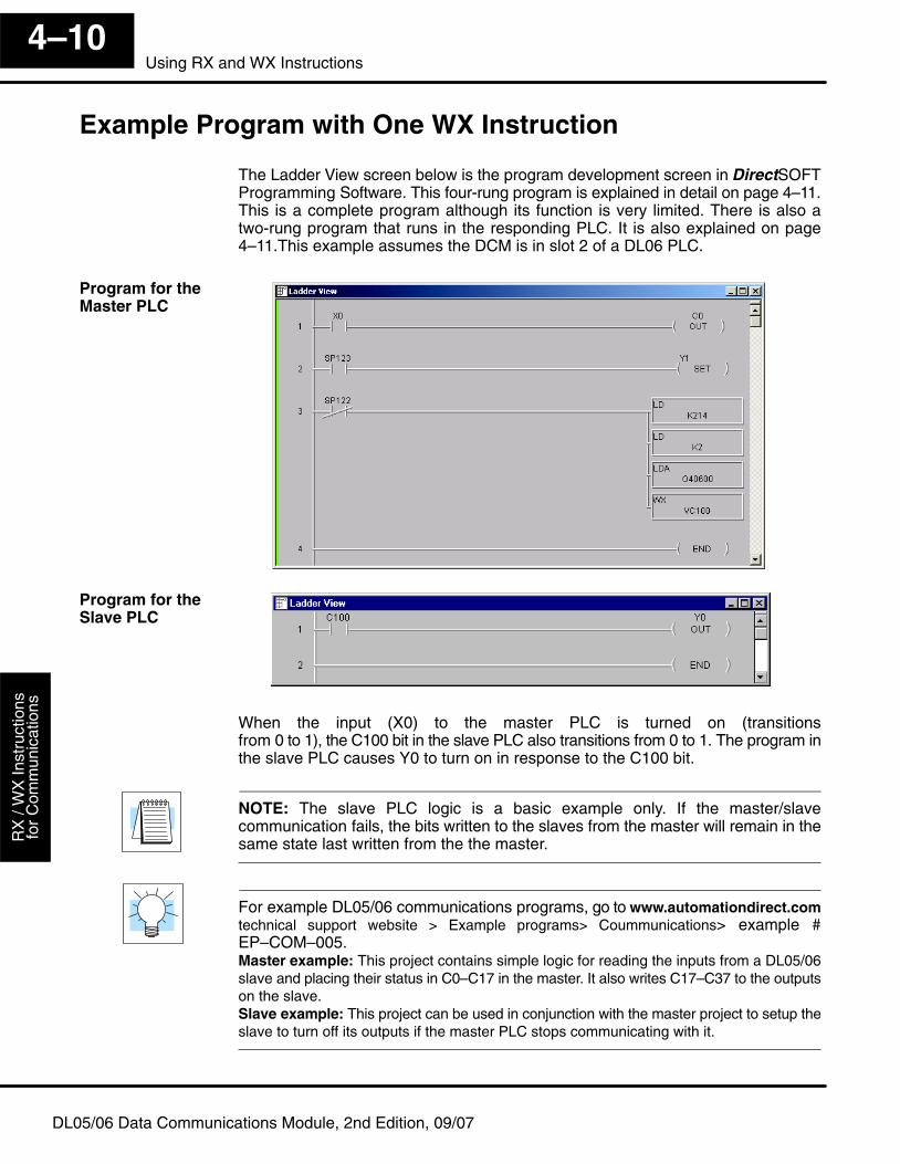
Get
ting
Sta
rted
Use
r App
licat
ion
Gui
delin
esR
X /
WX
Inst
ruct
ions
for
Com
mun
icat
ions
4–10Using RX and WX Instructions
DL05/06 Data Communications Module, 2nd Edition, 09/07
Example Program with One WX Instruction
The Ladder View screen below is the program development screen in DirectSOFTProgramming Software. This four-rung program is explained in detail on page 4–11.This is a complete program although its function is very limited. There is also atwo-rung program that runs in the responding PLC. It is also explained on page4–11.This example assumes the DCM is in slot 2 of a DL06 PLC.
When the input (X0) to the master PLC is turned on (transitionsfrom 0 to 1), the C100 bit in the slave PLC also transitions from 0 to 1. The program inthe slave PLC causes Y0 to turn on in response to the C100 bit.
NOTE: The slave PLC logic is a basic example only. If the master/slavecommunication fails, the bits written to the slaves from the master will remain in thesame state last written from the the master.
For example DL05/06 communications programs, go to www.automationdirect.comtechnical support website > Example programs> Coummunications> example #EP–COM–005. Master example: This project contains simple logic for reading the inputs from a DL05/06slave and placing their status in C0–C17 in the master. It also writes C17–C37 to the outputson the slave.Slave example: This project can be used in conjunction with the master project to setup theslave to turn off its outputs if the master PLC stops communicating with it.
Program for theMaster PLC
Program for theSlave PLC
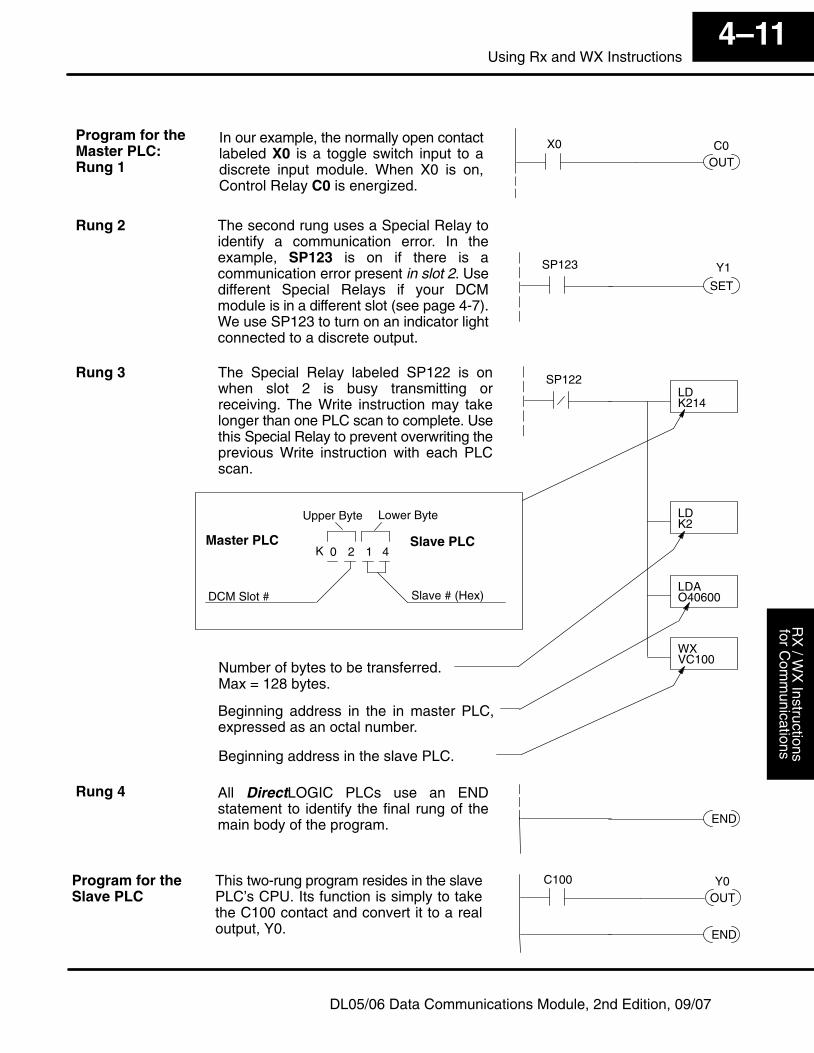
User A
pplicationG
uidelinesR
X / W
X Instructions
for Com
munications
4–11Using Rx and WX Instructions
DL05/06 Data Communications Module, 2nd Edition, 09/07
OUTC0X0In our example, the normally open contact
labeled X0 is a toggle switch input to adiscrete input module. When X0 is on,Control Relay C0 is energized.
SET
SP123 Y1
The second rung uses a Special Relay toidentify a communication error. In theexample, SP123 is on if there is acommunication error present in slot 2. Usedifferent Special Relays if your DCMmodule is in a different slot (see page 4-7).We use SP123 to turn on an indicator lightconnected to a discrete output.
LDK214
LDK2
LDAO40600
WXVC100
SP122The Special Relay labeled SP122 is onwhen slot 2 is busy transmitting orreceiving. The Write instruction may takelonger than one PLC scan to complete. Usethis Special Relay to prevent overwriting theprevious Write instruction with each PLCscan.
Number of bytes to be transferred.Max = 128 bytes.
Beginning address in the in master PLC,expressed as an octal number.
Beginning address in the slave PLC.
2 1 40
Slave # (Hex)
K
Upper Byte Lower Byte
Slave PLCMaster PLC
DCM Slot #
END
All DirectLOGIC PLCs use an ENDstatement to identify the final rung of themain body of the program.
END
OUTY0C100This two-rung program resides in the slave
PLC’s CPU. Its function is simply to takethe C100 contact and convert it to a realoutput, Y0.
Program for theMaster PLC: Rung 1
Rung 2
Rung 3
Rung 4
Program for theSlave PLC
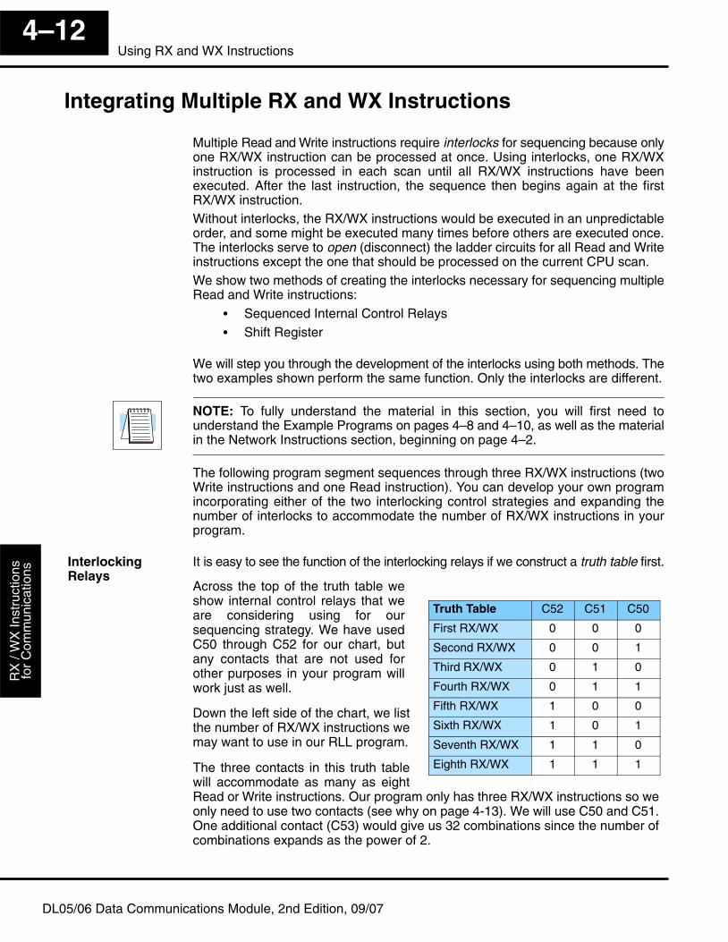
Get
ting
Sta
rted
Use
r App
licat
ion
Gui
delin
esR
X /
WX
Inst
ruct
ions
for
Com
mun
icat
ions
4–12Using RX and WX Instructions
DL05/06 Data Communications Module, 2nd Edition, 09/07
Integrating Multiple RX and WX Instructions
Multiple Read and Write instructions require interlocks for sequencing because onlyone RX/WX instruction can be processed at once. Using interlocks, one RX/WXinstruction is processed in each scan until all RX/WX instructions have beenexecuted. After the last instruction, the sequence then begins again at the firstRX/WX instruction. Without interlocks, the RX/WX instructions would be executed in an unpredictableorder, and some might be executed many times before others are executed once.The interlocks serve to open (disconnect) the ladder circuits for all Read and Writeinstructions except the one that should be processed on the current CPU scan.We show two methods of creating the interlocks necessary for sequencing multipleRead and Write instructions:
� Sequenced Internal Control Relays� Shift Register
We will step you through the development of the interlocks using both methods. Thetwo examples shown perform the same function. Only the interlocks are different.
NOTE: To fully understand the material in this section, you will first need tounderstand the Example Programs on pages 4–8 and 4–10, as well as the materialin the Network Instructions section, beginning on page 4–2.
The following program segment sequences through three RX/WX instructions (twoWrite instructions and one Read instruction). You can develop your own programincorporating either of the two interlocking control strategies and expanding thenumber of interlocks to accommodate the number of RX/WX instructions in yourprogram.
It is easy to see the function of the interlocking relays if we construct a truth table first.
Truth Table C52 C51 C50
First RX/WX 0 0 0
Second RX/WX 0 0 1
Third RX/WX 0 1 0
Fourth RX/WX 0 1 1
Fifth RX/WX 1 0 0
Sixth RX/WX 1 0 1
Seventh RX/WX 1 1 0
Eighth RX/WX 1 1 1
InterlockingRelays
Across the top of the truth table weshow internal control relays that weare considering using for oursequencing strategy. We have usedC50 through C52 for our chart, butany contacts that are not used forother purposes in your program willwork just as well.
Down the left side of the chart, we listthe number of RX/WX instructions wemay want to use in our RLL program.
The three contacts in this truth tablewill accommodate as many as eightRead or Write instructions. Our program only has three RX/WX instructions so weonly need to use two contacts (see why on page 4-13). We will use C50 and C51.One additional contact (C53) would give us 32 combinations since the number ofcombinations expands as the power of 2.
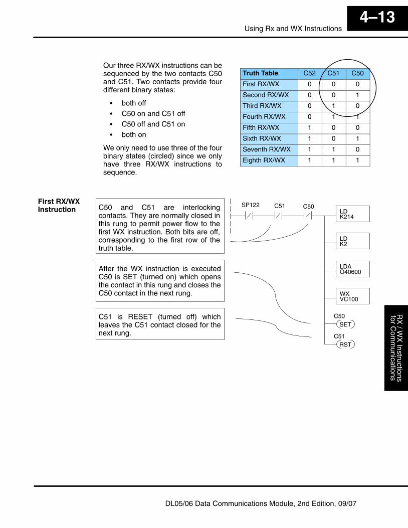
User A
pplicationG
uidelinesR
X / W
X Instructions
for Com
munications
4–13Using Rx and WX Instructions
DL05/06 Data Communications Module, 2nd Edition, 09/07
Truth Table C52 C51 C50
First RX/WX 0 0 0
Second RX/WX 0 0 1
Third RX/WX 0 1 0
Fourth RX/WX 0 1 1
Fifth RX/WX 1 0 0
Sixth RX/WX 1 0 1
Seventh RX/WX 1 1 0
Eighth RX/WX 1 1 1
LDK214
LDK2
LDAO40600
WXVC100
SP122
RSTC51
C51 C50
SETC50
C50 and C51 are interlockingcontacts. They are normally closed inthis rung to permit power flow to thefirst WX instruction. Both bits are off,corresponding to the first row of thetruth table.
After the WX instruction is executedC50 is SET (turned on) which opensthe contact in this rung and closes theC50 contact in the next rung.
C51 is RESET (turned off) whichleaves the C51 contact closed for thenext rung.
First RX/WXInstruction
Our three RX/WX instructions can besequenced by the two contacts C50and C51. Two contacts provide fourdifferent binary states:
� both off� C50 on and C51 off� C50 off and C51 on� both on
We only need to use three of the fourbinary states (circled) since we onlyhave three RX/WX instructions tosequence.
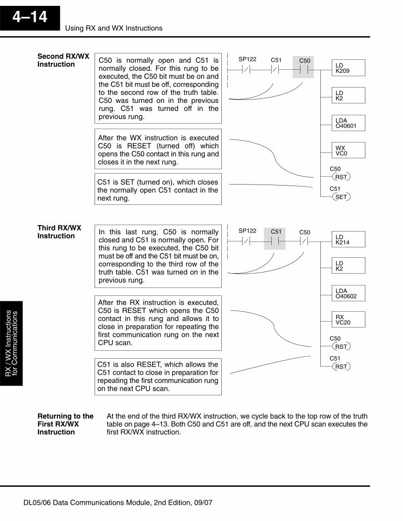
Get
ting
Sta
rted
Use
r App
licat
ion
Gui
delin
esR
X /
WX
Inst
ruct
ions
for
Com
mun
icat
ions
4–14Using RX and WX Instructions
DL05/06 Data Communications Module, 2nd Edition, 09/07
LDK209
LDK2
LDAO40601
WXVC0
SP122
SETC51
C51 C50
RSTC50
C50 is normally open and C51 isnormally closed. For this rung to beexecuted, the C50 bit must be on andthe C51 bit must be off, correspondingto the second row of the truth table.C50 was turned on in the previousrung. C51 was turned off in theprevious rung.
After the WX instruction is executedC50 is RESET (turned off) whichopens the C50 contact in this rung andcloses it in the next rung.
C51 is SET (turned on), which closesthe normally open C51 contact in thenext rung.
LDK214
LDK2
LDAO40602
RXVC20
SP122
RSTC51
C51 C50
RSTC50
In this last rung, C50 is normallyclosed and C51 is normally open. Forthis rung to be executed, the C50 bitmust be off and the C51 bit must be on,corresponding to the third row of thetruth table. C51 was turned on in theprevious rung.
After the RX instruction is executed,C50 is RESET which opens the C50contact in this rung and allows it toclose in preparation for repeating thefirst communication rung on the nextCPU scan.
C51 is also RESET, which allows theC51 contact to close in preparation forrepeating the first communication rungon the next CPU scan.
At the end of the third RX/WX instruction, we cycle back to the top row of the truthtable on page 4–13. Both C50 and C51 are off, and the next CPU scan executes thefirst RX/WX instruction.
Second RX/WXInstruction
Third RX/WXInstruction
Returning to theFirst RX/WXInstruction
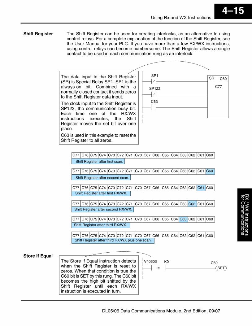
User A
pplicationG
uidelinesR
X / W
X Instructions
for Com
munications
4–15Using Rx and WX Instructions
DL05/06 Data Communications Module, 2nd Edition, 09/07
The Shift Register can be used for creating interlocks, as an alternative to usingcontrol relays. For a complete explanation of the function of the Shift Register, seethe User Manual for your PLC. If you have more than a few RX/WX instructions,using control relays can become cumbersome. The Shift Register allows a singlecontact to be used in each communication rung as an interlock.
SRSP1The data input to the Shift Register
(SR) is Special Relay SP1. SP1 is thealways-on bit. Combined with anormally closed contact it sends zerosto the Shift Register data input.
The clock input to the Shift Register isSP122, the communication busy bit.Each time one of the RX/WXinstructions executes, the ShiftRegister moves the set bit over oneplace.
C63 is used in this example to reset theShift Register to all zeros.
C60
C77SP122
C63
Shift Register after first RX/WX.
C74 C73 C72 C71 C70 C67 C66 C65 C64 C63 C62 C61 C60C75C76C77
Shift Register after first scan.
C74 C73 C72 C71 C70 C67 C66 C65 C64 C63 C62 C61 C60C75C76C77
C74 C73 C72 C71 C70 C67 C66 C65 C64 C63 C62 C61 C60C75C76C77
C74 C73 C72 C71 C70 C67 C66 C65 C64 C63 C62 C61 C60C75C76C77
C74 C73 C72 C71 C70 C67 C66 C65 C64 C63 C62 C61 C60C75C76C77
Shift Register after second RX/WX.
Shift Register after second scan.
C74 C73 C72 C71 C70 C67 C66 C65 C64 C63 C62 C61 C60C75C76C77
Shift Register after third RX/WX.
Shift Register after third RX/WX plus one scan.
V40603The Store If Equal instruction detectswhen the Shift Register is reset tozeros. When that condition is true theC60 bit is SET by this rung. The C60 bitbecomes the high bit shifted by theShift Register until each RX/WXinstruction is executed in turn.
SET=
K0 C60
Shift Register
Store If Equal
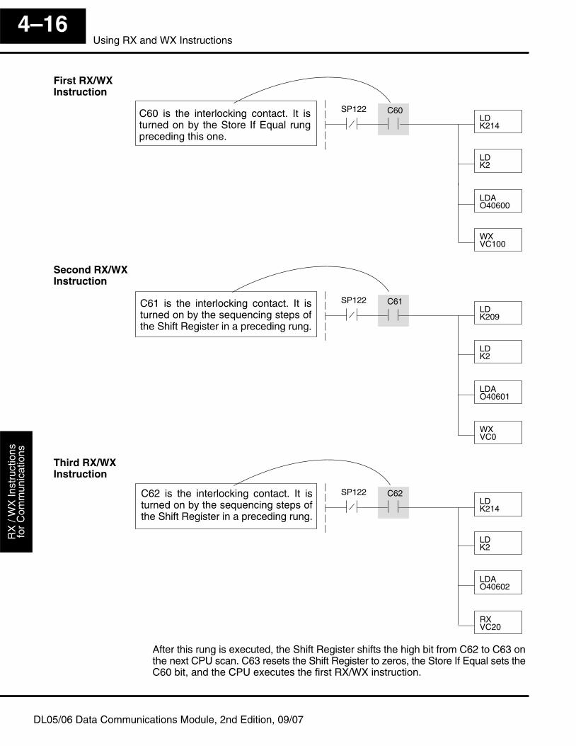
Get
ting
Sta
rted
Use
r App
licat
ion
Gui
delin
esR
X /
WX
Inst
ruct
ions
for
Com
mun
icat
ions
4–16Using RX and WX Instructions
DL05/06 Data Communications Module, 2nd Edition, 09/07
LDK214
LDK2
LDAO40600
WXVC100
SP122 C60C60 is the interlocking contact. It isturned on by the Store If Equal rungpreceding this one.
LDK209
LDK2
LDAO40601
WXVC0
SP122 C61C61 is the interlocking contact. It isturned on by the sequencing steps ofthe Shift Register in a preceding rung.
LDK214
LDK2
LDAO40602
RXVC20
SP122 C62C62 is the interlocking contact. It isturned on by the sequencing steps ofthe Shift Register in a preceding rung.
After this rung is executed, the Shift Register shifts the high bit from C62 to C63 onthe next CPU scan. C63 resets the Shift Register to zeros, the Store If Equal sets theC60 bit, and the CPU executes the first RX/WX instruction.
First RX/WXInstruction
Second RX/WXInstruction
Third RX/WXInstruction
15Modbus� RTUCommunicationsRX/WX and MRX/MWX
In This Chapter. . . .— Network Slave Operation— Network Master Operation: RX / WX— Network Master Operation: DL06 MRX / MWX
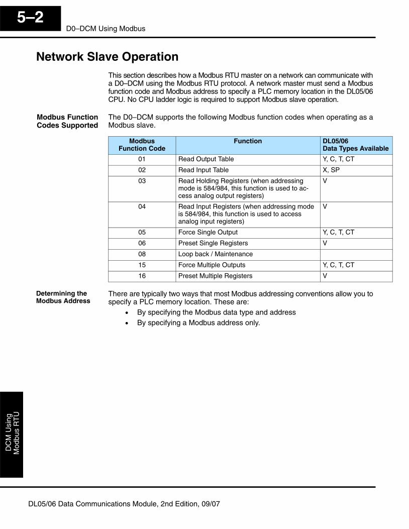
Mod
bus
RT
UD
CM
Usi
ng
5–2D0–DCM Using Modbus
DL05/06 Data Communications Module, 2nd Edition, 09/07
Network Slave OperationThis section describes how a Modbus RTU master on a network can communicate witha D0–DCM using the Modbus RTU protocol. A network master must send a Modbusfunction code and Modbus address to specify a PLC memory location in the DL05/06CPU. No CPU ladder logic is required to support Modbus slave operation.
The D0–DCM supports the following Modbus function codes when operating as aModbus slave.
ModbusFunction Code
Function DL05/06Data Types Available
01 Read Output Table Y, C, T, CT
02 Read Input Table X, SP
03 Read Holding Registers (when addressingmode is 584/984, this function is used to ac-cess analog output registers)
V
04 Read Input Registers (when addressing modeis 584/984, this function is used to access analog input registers)
V
05 Force Single Output Y, C, T, CT
06 Preset Single Registers V
08 Loop back / Maintenance
15 Force Multiple Outputs Y, C, T, CT
16 Preset Multiple Registers V
There are typically two ways that most Modbus addressing conventions allow you tospecify a PLC memory location. These are:
• By specifying the Modbus data type and address• By specifying a Modbus address only.
Modbus FunctionCodes Supported
Determining theModbus Address
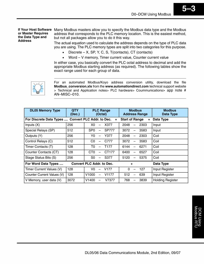
Modbus R
TU
DC
M U
singInstallation and
5–3D0–DCM Using Modbus
DL05/06 Data Communications Module, 2nd Edition, 09/07
Many Modbus masters allow you to specify the Modbus data type and the Modbusaddress that corresponds to the PLC memory location. This is the easiest method,but not all packages allow you to do it this way.The actual equation used to calculate the address depends on the type of PLC datayou are using. The PLC memory types are split into two categories for this purpose.
• Discrete – X, SP, Y, C, S, T(contacts), CT (contacts)• Word – V memory, Timer current value, Counter current value
In either case, you basically convert the PLC octal address to decimal and add theappropriate Modbus starting address (as required). The following tables show theexact range used for each group of data.
For an automated Modbus/Koyo address conversion utility, download the fileModbus_conversion.xls from the www.automationdirect.com technical support website> Technical and Application notes> PLC hardware> Coummunications> app note #AN–MISC–010.
DL05 Memory Type QTY(Dec.)
PLC Range(Octal)
ModbusAddress Range
ModbusData Type
For Discrete Data Types .... Convert PLC Addr. to Dec. + Start of Range + Data Type
Inputs (X) 256 X0 – X377 2048 – 2303 Input
Special Relays (SP) 512 SP0 – SP777 3072 – 3583 Input
Outputs (Y) 256 Y0 – Y377 2048 – 2303 Coil
Control Relays (C) 512 C0 – C777 3072 – 3583 Coil
Timer Contacts (T) 128 T0 – T177 6144 – 6271 Coil
Counter Contacts (CT) 128 CT0 – CT177 6400 – 6527 Coil
Stage Status Bits (S) 256 S0 – S377 5120 – 5375 Coil
For Word Data Types .... Convert PLC Addr. to Dec. + Data Type
Timer Current Values (V) 128 V0 – V177 0 – 127 Input Register
Counter Current Values (V) 128 V1000 – V1177 512 – 639 Input Register
V Memory, user data (V) 3072 V1400 – V7377 768 – 3839 Holding Register
If Your Host Softwareor Master Requiresthe Data Type andAddress
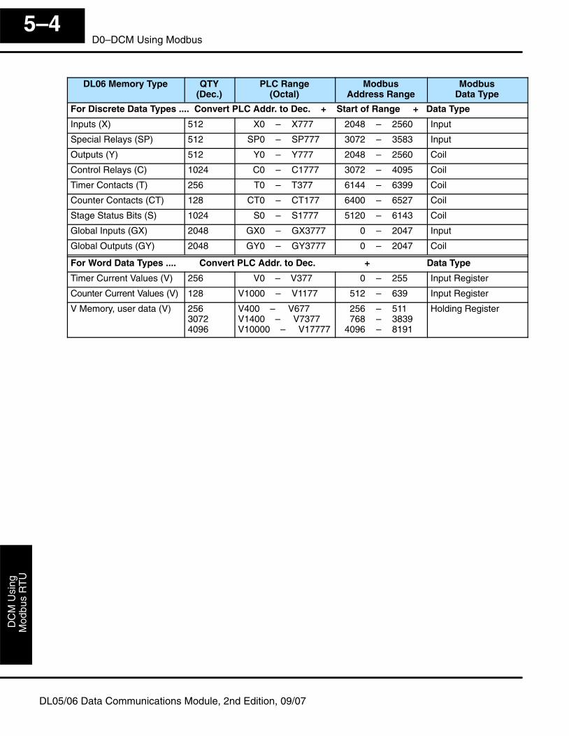
Mod
bus
RT
UD
CM
Usi
ng
5–4D0–DCM Using Modbus
DL05/06 Data Communications Module, 2nd Edition, 09/07
DL06 Memory Type QTY(Dec.)
PLC Range(Octal)
ModbusAddress Range
ModbusData Type
For Discrete Data Types .... Convert PLC Addr. to Dec. + Start of Range + Data Type
Inputs (X) 512 X0 – X777 2048 – 2560 Input
Special Relays (SP) 512 SP0 – SP777 3072 – 3583 Input
Outputs (Y) 512 Y0 – Y777 2048 – 2560 Coil
Control Relays (C) 1024 C0 – C1777 3072 – 4095 Coil
Timer Contacts (T) 256 T0 – T377 6144 – 6399 Coil
Counter Contacts (CT) 128 CT0 – CT177 6400 – 6527 Coil
Stage Status Bits (S) 1024 S0 – S1777 5120 – 6143 Coil
Global Inputs (GX) 2048 GX0 – GX3777 0 – 2047 Input
Global Outputs (GY) 2048 GY0 – GY3777 0 – 2047 Coil
For Word Data Types .... Convert PLC Addr. to Dec. + Data Type
Timer Current Values (V) 256 V0 – V377 0 – 255 Input Register
Counter Current Values (V) 128 V1000 – V1177 512 – 639 Input Register
V Memory, user data (V) 25630724096
V400 – V677V1400 – V7377V10000 – V17777
256 – 511768 – 3839
4096 – 8191
Holding Register
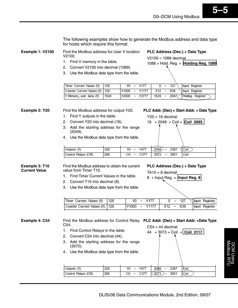
Modbus R
TU
DC
M U
singInstallation and
5–5D0–DCM Using Modbus
DL05/06 Data Communications Module, 2nd Edition, 09/07
The following examples show how to generate the Modbus address and data typefor hosts which require this format.
Find the Modbus address for User V locationV2100.
1. Find V memory in the table.
2. Convert V2100 into decimal (1089).
3. Use the Modbus data type from the table.
PLC Address (Dec.) + Data Type
V2100 = 1088 decimal1088 + Hold. Reg. = Holding Reg. 1089
Find the Modbus address for output Y20.
1. Find Y outputs in the table.
2. Convert Y20 into decimal (16).
3. Add the starting address for the range(2049).
4. Use the Modbus data type from the table.
PLC Addr. (Dec) + Start Addr. + Data Type
Y20 = 16 decimal16 + 2049 + Coil = Coil 2065
Find the Modbus address to obtain the currentvalue from Timer T10.
1. Find Timer Current Values in the table.
2. Convert T10 into decimal (8).
3. Use the Modbus data type from the table.
PLC Address (Dec.) + Data Type
TA10 = 8 decimal8 + Input Reg. = Input Reg. 8
Find the Modbus address for Control RelayC54.
1. Find Control Relays in the table.
2. Convert C54 into decimal (44).
3. Add the starting address for the range(3072).
4. Use the Modbus data type from the table.
PLC Addr. (Dec) + Start Addr. +Data Type
C54 = 44 decimal44 + 3073 + Coil = Coil 3117
Example 1: V2100
Example 2: Y20
Example 3: T10Current Value
Example 4: C54
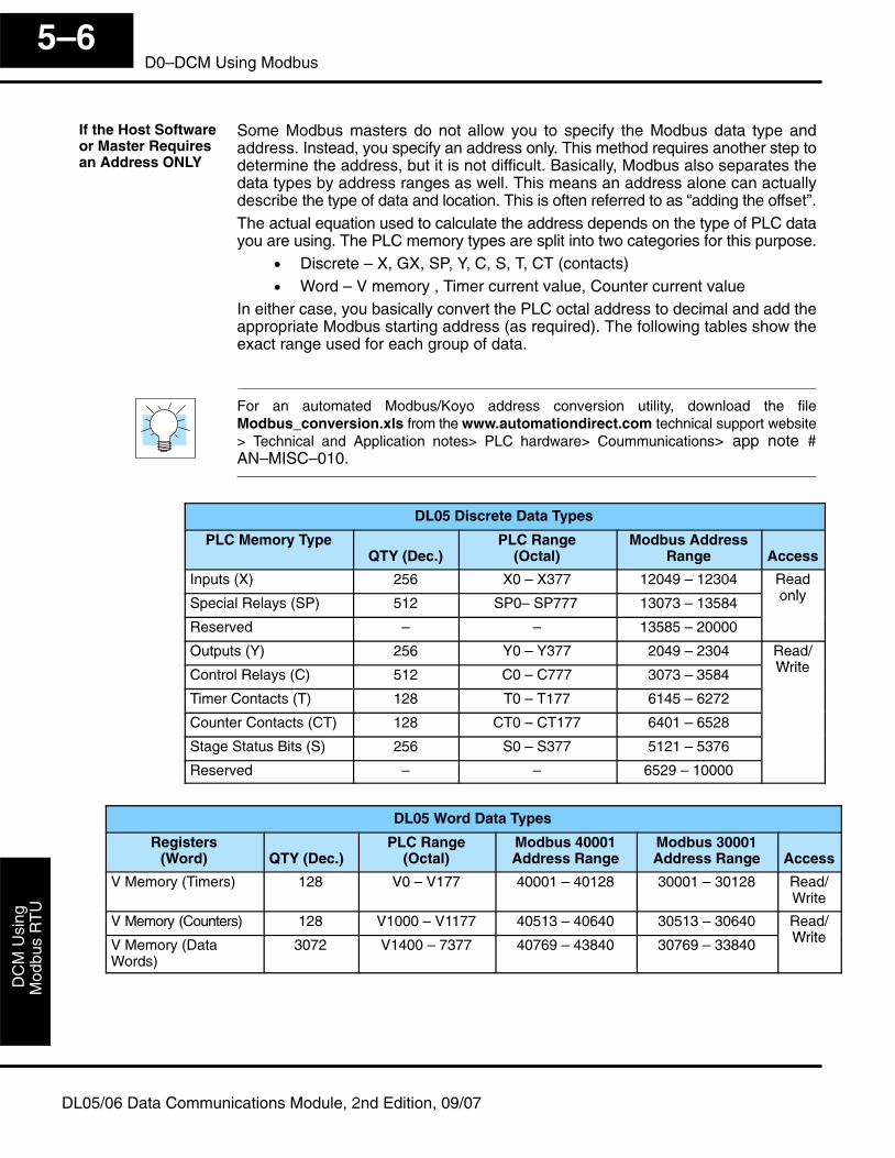
Mod
bus
RT
UD
CM
Usi
ng
5–6D0–DCM Using Modbus
DL05/06 Data Communications Module, 2nd Edition, 09/07
Some Modbus masters do not allow you to specify the Modbus data type andaddress. Instead, you specify an address only. This method requires another step todetermine the address, but it is not difficult. Basically, Modbus also separates thedata types by address ranges as well. This means an address alone can actuallydescribe the type of data and location. This is often referred to as “adding the offset”.The actual equation used to calculate the address depends on the type of PLC datayou are using. The PLC memory types are split into two categories for this purpose.
• Discrete – X, GX, SP, Y, C, S, T, CT (contacts)• Word – V memory , Timer current value, Counter current value
In either case, you basically convert the PLC octal address to decimal and add theappropriate Modbus starting address (as required). The following tables show theexact range used for each group of data.
For an automated Modbus/Koyo address conversion utility, download the fileModbus_conversion.xls from the www.automationdirect.com technical support website> Technical and Application notes> PLC hardware> Coummunications> app note #AN–MISC–010.
DL05 Discrete Data Types
PLC Memory TypeQTY (Dec.)
PLC Range(Octal)
Modbus AddressRange Access
Inputs (X) 256 X0 – X377 12049 – 12304 ReadonlySpecial Relays (SP) 512 SP0– SP777 13073 – 13584 only
Reserved – – 13585 – 20000
Outputs (Y) 256 Y0 – Y377 2049 – 2304 Read/WriteControl Relays (C) 512 C0 – C777 3073 – 3584 Write
Timer Contacts (T) 128 T0 – T177 6145 – 6272
Counter Contacts (CT) 128 CT0 – CT177 6401 – 6528
Stage Status Bits (S) 256 S0 – S377 5121 – 5376
Reserved – – 6529 – 10000
DL05 Word Data Types
Registers(Word) QTY (Dec.)
PLC Range(Octal)
Modbus 40001Address Range
Modbus 30001Address Range Access
V Memory (Timers) 128 V0 – V177 40001 – 40128 30001 – 30128 Read/Write
V Memory (Counters) 128 V1000 – V1177 40513 – 40640 30513 – 30640 Read/WriteV Memory (Data
Words)3072 V1400 – 7377 40769 – 43840 30769 – 33840 Write
If the Host Softwareor Master Requiresan Address ONLY
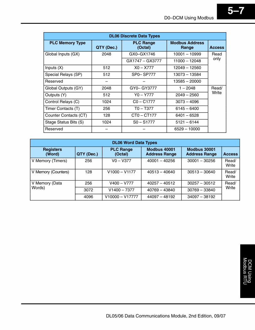
Modbus R
TU
DC
M U
singInstallation and
5–7D0–DCM Using Modbus
DL05/06 Data Communications Module, 2nd Edition, 09/07
DL06 Discrete Data Types
PLC Memory TypeQTY (Dec.)
PLC Range(Octal)
Modbus AddressRange Access
Global Inputs (GX) 2048 GX0–GX1746 10001 – 10999 ReadonlyGX1747 – GX3777 11000 – 12048 only
Inputs (X) 512 X0 – X777 12049 – 12560
Special Relays (SP) 512 SP0– SP777 13073 – 13584
Reserved – – 13585 – 20000
Global Outputs (GY) 2048 GY0– GY3777 1 – 2048 Read/WriteOutputs (Y) 512 Y0 – Y777 2049 – 2560 Write
Control Relays (C) 1024 C0 – C1777 3073 – 4096
Timer Contacts (T) 256 T0 – T377 6145 – 6400
Counter Contacts (CT) 128 CT0 – CT177 6401 – 6528
Stage Status Bits (S) 1024 S0 – S1777 5121 – 6144
Reserved – – 6529 – 10000
DL06 Word Data Types
Registers(Word) QTY (Dec.)
PLC Range(Octal)
Modbus 40001Address Range
Modbus 30001Address Range Access
V Memory (Timers) 256 V0 – V377 40001 – 40256 30001 – 30256 Read/Write
V Memory (Counters) 128 V1000 – V1177 40513 – 40640 30513 – 30640 Read/Write
V Memory (DataWords)
256 V400 – V777 40257 – 40512 30257 – 30512 Read/WriteWords) 3072 V1400 – 7377 40769 – 43840 30769 – 33840 Write
4096 V10000 – V17777 44097 – 48192 34097 – 38192
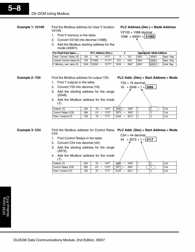
Mod
bus
RT
UD
CM
Usi
ng
5–8D0–DCM Using Modbus
DL05/06 Data Communications Module, 2nd Edition, 09/07
Find the Modbus address for User V locationV2100.
1. Find V memory in the table.
2. Convert V2100 into decimal (1088).
3. Add the Modbus starting address for themode (40001).
PLC Address (Dec.) + Mode Address
V2100 = 1088 decimal1088 + 40001 = 41089
Find the Modbus address for output Y20.
1. Find Y outputs in the table.
2. Convert Y20 into decimal (16).
3. Add the starting address for the range(2048).
4. Add the Modbus address for the mode(1).
PLC Addr. (Dec) + Start Address + Mode
Y20 = 16 decimal16 + 2048 + 1 = 2065
Find the Modbus address for Control RelayC54.
1. Find Control Relays in the table.
2. Convert C54 into decimal (44).
3. Add the starting address for the range(3072).
4. Add the Modbus address for the mode(1).
PLC Addr. (Dec) + Start Address + Mode
C54 = 44 decimal44 + 3072 + 1 = 3117
Example 1: V2100
Example 2: Y20
Example 3: C54
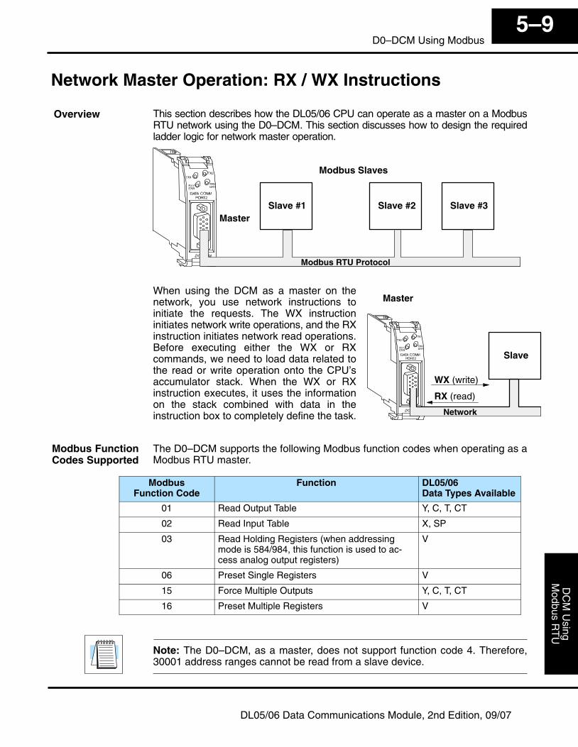
Modbus R
TU
DC
M U
singInstallation and
5–9D0–DCM Using Modbus
DL05/06 Data Communications Module, 2nd Edition, 09/07
Network Master Operation: RX / WX Instructions
This section describes how the DL05/06 CPU can operate as a master on a ModbusRTU network using the D0–DCM. This section discusses how to design the requiredladder logic for network master operation.
Slave #1 Slave #3Master
Modbus RTU Protocol
Slave #2
Modbus Slaves
When using the DCM as a master on thenetwork, you use network instructions toinitiate the requests. The WX instructioninitiates network write operations, and the RXinstruction initiates network read operations.Before executing either the WX or RXcommands, we need to load data related tothe read or write operation onto the CPU’saccumulator stack. When the WX or RXinstruction executes, it uses the informationon the stack combined with data in theinstruction box to completely define the task.
Slave
Master
WX (write)
RX (read)
Network
The D0–DCM supports the following Modbus function codes when operating as aModbus RTU master.
ModbusFunction Code
Function DL05/06Data Types Available
01 Read Output Table Y, C, T, CT
02 Read Input Table X, SP
03 Read Holding Registers (when addressingmode is 584/984, this function is used to ac-cess analog output registers)
V
06 Preset Single Registers V
15 Force Multiple Outputs Y, C, T, CT
16 Preset Multiple Registers V
Note: The D0–DCM, as a master, does not support function code 4. Therefore,30001 address ranges cannot be read from a slave device.
Overview
Modbus FunctionCodes Supported
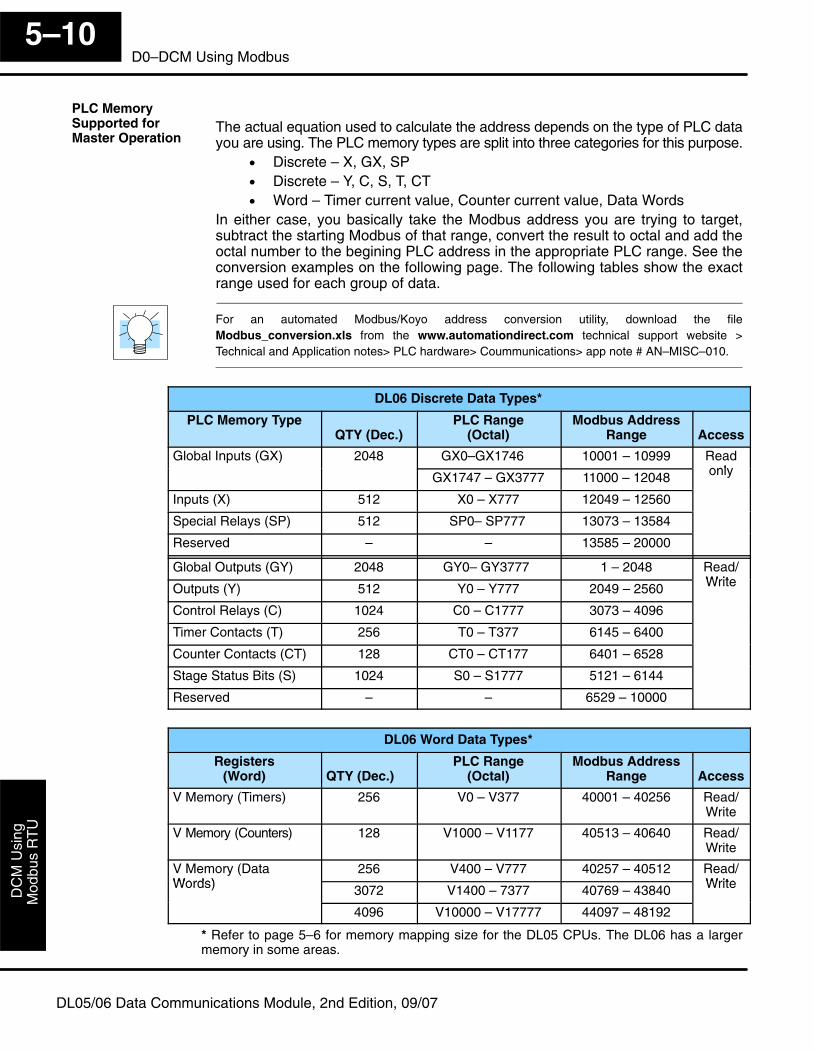
Mod
bus
RT
UD
CM
Usi
ng
5–10D0–DCM Using Modbus
DL05/06 Data Communications Module, 2nd Edition, 09/07
The actual equation used to calculate the address depends on the type of PLC datayou are using. The PLC memory types are split into three categories for this purpose.
• Discrete – X, GX, SP• Discrete – Y, C, S, T, CT• Word – Timer current value, Counter current value, Data Words
In either case, you basically take the Modbus address you are trying to target,subtract the starting Modbus of that range, convert the result to octal and add theoctal number to the begining PLC address in the appropriate PLC range. See theconversion examples on the following page. The following tables show the exactrange used for each group of data.
For an automated Modbus/Koyo address conversion utility, download the fileModbus_conversion.xls from the www.automationdirect.com technical support website >Technical and Application notes> PLC hardware> Coummunications> app note # AN–MISC–010.
DL06 Discrete Data Types*
PLC Memory TypeQTY (Dec.)
PLC Range(Octal)
Modbus AddressRange Access
Global Inputs (GX) 2048 GX0–GX1746 10001 – 10999 ReadonlyGX1747 – GX3777 11000 – 12048 only
Inputs (X) 512 X0 – X777 12049 – 12560
Special Relays (SP) 512 SP0– SP777 13073 – 13584
Reserved – – 13585 – 20000
Global Outputs (GY) 2048 GY0– GY3777 1 – 2048 Read/WriteOutputs (Y) 512 Y0 – Y777 2049 – 2560 Write
Control Relays (C) 1024 C0 – C1777 3073 – 4096
Timer Contacts (T) 256 T0 – T377 6145 – 6400
Counter Contacts (CT) 128 CT0 – CT177 6401 – 6528
Stage Status Bits (S) 1024 S0 – S1777 5121 – 6144
Reserved – – 6529 – 10000
DL06 Word Data Types*
Registers(Word) QTY (Dec.)
PLC Range(Octal)
Modbus AddressRange Access
V Memory (Timers) 256 V0 – V377 40001 – 40256 Read/Write
V Memory (Counters) 128 V1000 – V1177 40513 – 40640 Read/Write
V Memory (DataWords)
256 V400 – V777 40257 – 40512 Read/WriteWords) 3072 V1400 – 7377 40769 – 43840 Write
4096 V10000 – V17777 44097 – 48192
* Refer to page 5–6 for memory mapping size for the DL05 CPUs. The DL06 has a largermemory in some areas.
PLC MemorySupported for Master Operation
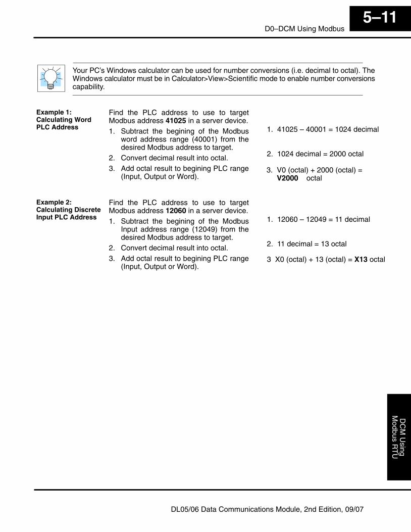
Modbus R
TU
DC
M U
singInstallation and
5–11D0–DCM Using Modbus
DL05/06 Data Communications Module, 2nd Edition, 09/07
Your PC’s Windows calculator can be used for number conversions (i.e. decimal to octal). TheWindows calculator must be in Calculator>View>Scientific mode to enable number conversionscapability.
Find the PLC address to use to targetModbus address 41025 in a server device.1. Subtract the begining of the Modbus
word address range (40001) from thedesired Modbus address to target.
2. Convert decimal result into octal.3. Add octal result to begining PLC range
(Input, Output or Word).
2. 1024 decimal = 2000 octal
1. 41025 – 40001 = 1024 decimal
3. V0 (octal) + 2000 (octal) = V2000 octal
Find the PLC address to use to targetModbus address 12060 in a server device.1. Subtract the begining of the Modbus
Input address range (12049) from thedesired Modbus address to target.
2. Convert decimal result into octal.3. Add octal result to begining PLC range
(Input, Output or Word).
2. 11 decimal = 13 octal
1. 12060 – 12049 = 11 decimal
3 X0 (octal) + 13 (octal) = X13 octal
Example 1:Calculating WordPLC Address
Example 2:Calculating DiscreteInput PLC Address
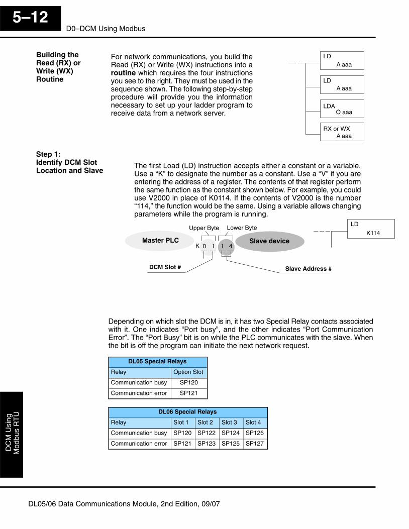
Mod
bus
RT
UD
CM
Usi
ng
5–12D0–DCM Using Modbus
DL05/06 Data Communications Module, 2nd Edition, 09/07
For network communications, you build theRead (RX) or Write (WX) instructions into aroutine which requires the four instructionsyou see to the right. They must be used in thesequence shown. The following step-by-stepprocedure will provide you the informationnecessary to set up your ladder program toreceive data from a network server.
LDAO aaa
LDA aaa
LDA aaa
RX or WXA aaa
LD
K114
1 1 40K
Upper Byte Lower Byte
Slave deviceMaster PLC
Slave Address #
The first Load (LD) instruction accepts either a constant or a variable.Use a “K” to designate the number as a constant. Use a “V” if you areentering the address of a register. The contents of that register performthe same function as the constant shown below. For example, you coulduse V2000 in place of K0114. If the contents of V2000 is the number“114,” the function would be the same. Using a variable allows changingparameters while the program is running.
DCM Slot #
Depending on which slot the DCM is in, it has two Special Relay contacts associatedwith it. One indicates “Port busy”, and the other indicates “Port CommunicationError”. The “Port Busy” bit is on while the PLC communicates with the slave. Whenthe bit is off the program can initiate the next network request.
DL05 Special Relays
Relay Option Slot
Communication busy SP120
Communication error SP121
DL06 Special Relays
Relay Slot 1 Slot 2 Slot 3 Slot 4
Communication busy SP120 SP122 SP124 SP126
Communication error SP121 SP123 SP125 SP127
Building the Read (RX) orWrite (WX) Routine
Step 1:Identify DCM SlotLocation and Slave
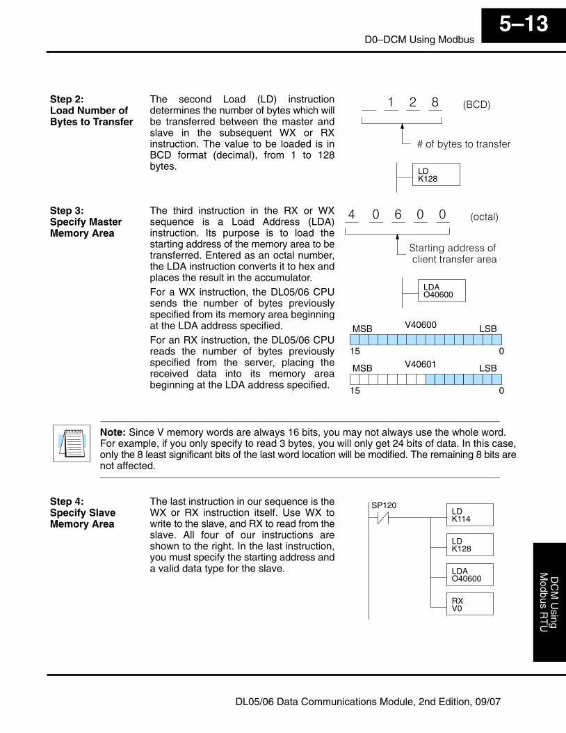
Modbus R
TU
DC
M U
singInstallation and
5–13D0–DCM Using Modbus
DL05/06 Data Communications Module, 2nd Edition, 09/07
The second Load (LD) instructiondetermines the number of bytes which willbe transferred between the master andslave in the subsequent WX or RXinstruction. The value to be loaded is inBCD format (decimal), from 1 to 128bytes.
� � � ����
�� ��������������� ��
LDK128
The third instruction in the RX or WXsequence is a Load Address (LDA)instruction. Its purpose is to load thestarting address of the memory area to betransferred. Entered as an octal number,the LDA instruction converts it to hex andplaces the result in the accumulator.For a WX instruction, the DL05/06 CPUsends the number of bytes previouslyspecified from its memory area beginningat the LDA address specified.For an RX instruction, the DL05/06 CPUreads the number of bytes previouslyspecified from the server, placing thereceived data into its memory areabeginning at the LDA address specified.
� � �� ������
LDAO40600
�
������������������ ������������� �������
V40600MSB LSB
015V40601MSB LSB
015
Note: Since V memory words are always 16 bits, you may not always use the whole word. For example, if you only specify to read 3 bytes, you will only get 24 bits of data. In this case,only the 8 least significant bits of the last word location will be modified. The remaining 8 bits arenot affected.
The last instruction in our sequence is theWX or RX instruction itself. Use WX towrite to the slave, and RX to read from theslave. All four of our instructions areshown to the right. In the last instruction,you must specify the starting address anda valid data type for the slave.
LDK114
LDK128
LDAO40600
RXV0
SP120
Step 2:Load Number ofBytes to Transfer
Step 3:Specify MasterMemory Area
Step 4:Specify SlaveMemory Area
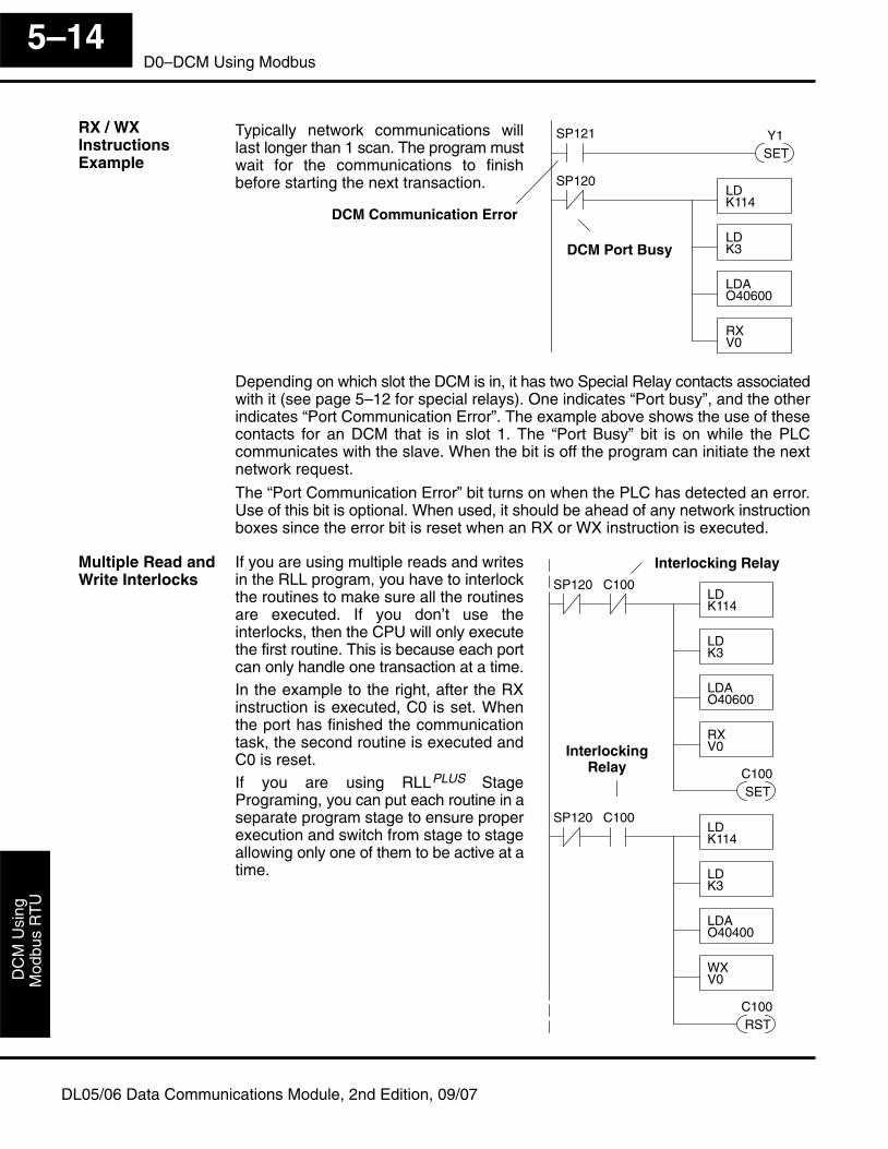
Mod
bus
RT
UD
CM
Usi
ng
5–14D0–DCM Using Modbus
DL05/06 Data Communications Module, 2nd Edition, 09/07
Typically network communications willlast longer than 1 scan. The program mustwait for the communications to finishbefore starting the next transaction.
DCM Communication Error
LDK114
LDK3
LDAO40600
RXV0
SP120
DCM Port Busy
SP121
SETY1
Depending on which slot the DCM is in, it has two Special Relay contacts associatedwith it (see page 5–12 for special relays). One indicates “Port busy”, and the otherindicates “Port Communication Error”. The example above shows the use of thesecontacts for an DCM that is in slot 1. The “Port Busy” bit is on while the PLCcommunicates with the slave. When the bit is off the program can initiate the nextnetwork request.
The “Port Communication Error” bit turns on when the PLC has detected an error.Use of this bit is optional. When used, it should be ahead of any network instructionboxes since the error bit is reset when an RX or WX instruction is executed.
If you are using multiple reads and writesin the RLL program, you have to interlockthe routines to make sure all the routinesare executed. If you don’t use theinterlocks, then the CPU will only executethe first routine. This is because each portcan only handle one transaction at a time.In the example to the right, after the RXinstruction is executed, C0 is set. Whenthe port has finished the communicationtask, the second routine is executed andC0 is reset.If you are using RLLPLUS StagePrograming, you can put each routine in aseparate program stage to ensure properexecution and switch from stage to stageallowing only one of them to be active at atime.
Interlocking Relay
LDK114
LDK3
LDAO40600
RXV0
SP120
SETC100
C100
LDK114
LDK3
LDAO40400
WXV0
SP120
RSTC100
C100
InterlockingRelay
RX / WXInstructionsExample
Multiple Read andWrite Interlocks
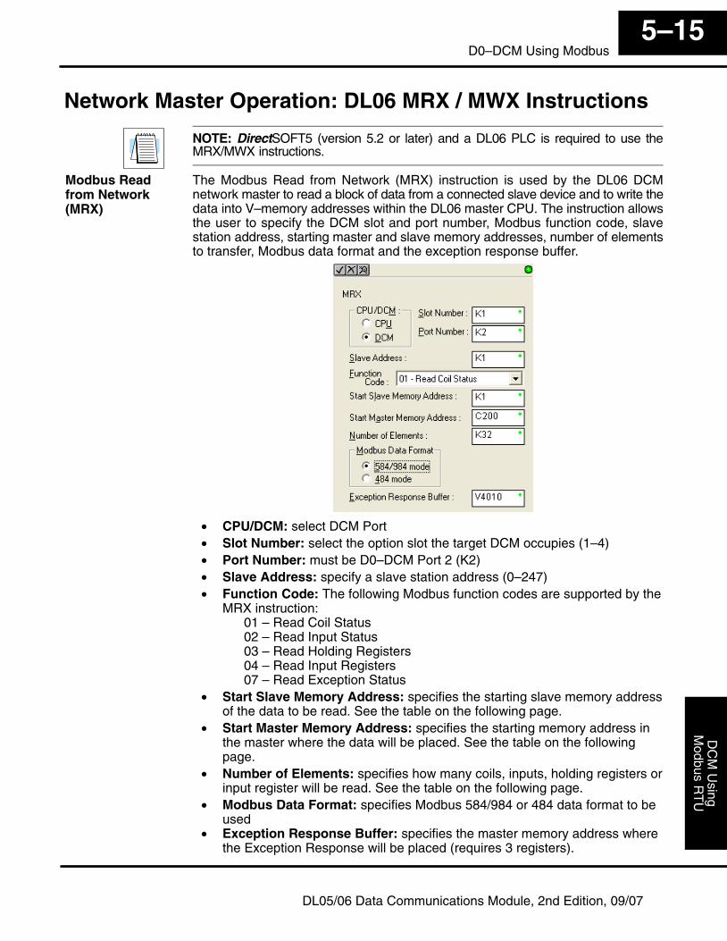
Modbus R
TU
DC
M U
singInstallation and
5–15D0–DCM Using Modbus
DL05/06 Data Communications Module, 2nd Edition, 09/07
Network Master Operation: DL06 MRX / MWX Instructions
NOTE: DirectSOFT5 (version 5.2 or later) and a DL06 PLC is required to use theMRX/MWX instructions.
The Modbus Read from Network (MRX) instruction is used by the DL06 DCMnetwork master to read a block of data from a connected slave device and to write thedata into V–memory addresses within the DL06 master CPU. The instruction allowsthe user to specify the DCM slot and port number, Modbus function code, slavestation address, starting master and slave memory addresses, number of elementsto transfer, Modbus data format and the exception response buffer.
• CPU/DCM: select DCM Port• Slot Number: select the option slot the target DCM occupies (1–4)• Port Number: must be D0–DCM Port 2 (K2)• Slave Address: specify a slave station address (0–247)• Function Code: The following Modbus function codes are supported by the
MRX instruction:01 – Read Coil Status02 – Read Input Status03 – Read Holding Registers04 – Read Input Registers07 – Read Exception Status
• Start Slave Memory Address: specifies the starting slave memory addressof the data to be read. See the table on the following page.
• Start Master Memory Address: specifies the starting memory address inthe master where the data will be placed. See the table on the followingpage.
• Number of Elements: specifies how many coils, inputs, holding registers orinput register will be read. See the table on the following page.
• Modbus Data Format: specifies Modbus 584/984 or 484 data format to beused
• Exception Response Buffer: specifies the master memory address wherethe Exception Response will be placed (requires 3 registers).
Modbus Read from Network(MRX)
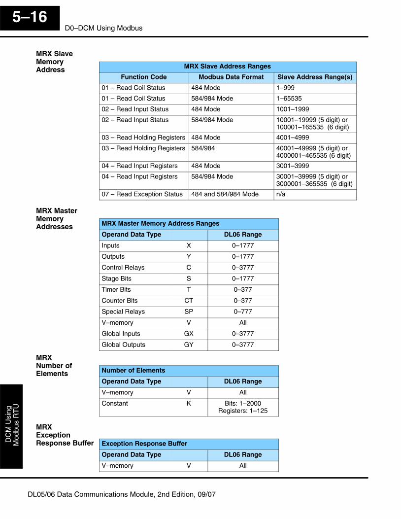
Mod
bus
RT
UD
CM
Usi
ng
5–16D0–DCM Using Modbus
DL05/06 Data Communications Module, 2nd Edition, 09/07
MRX Slave Address Ranges
Function Code Modbus Data Format Slave Address Range(s)
01 – Read Coil Status 484 Mode 1–999
01 – Read Coil Status 584/984 Mode 1–65535
02 – Read Input Status 484 Mode 1001–1999
02 – Read Input Status 584/984 Mode 10001–19999 (5 digit) or100001–165535 (6 digit)
03 – Read Holding Registers 484 Mode 4001–4999
03 – Read Holding Registers 584/984 40001–49999 (5 digit) or 4000001–465535 (6 digit)
04 – Read Input Registers 484 Mode 3001–3999
04 – Read Input Registers 584/984 Mode 30001–39999 (5 digit) or3000001–365535 (6 digit)
07 – Read Exception Status 484 and 584/984 Mode n/a
MRX Master Memory Address Ranges
Operand Data Type DL06 Range
Inputs X 0–1777
Outputs Y 0–1777
Control Relays C 0–3777
Stage Bits S 0–1777
Timer Bits T 0–377
Counter Bits CT 0–377
Special Relays SP 0–777
V–memory V All
Global Inputs GX 0–3777
Global Outputs GY 0–3777
Number of Elements
Operand Data Type DL06 Range
V–memory V All
Constant K Bits: 1–2000Registers: 1–125
Exception Response Buffer
Operand Data Type DL06 Range
V–memory V All
MRX Slave Memory Address
MRX MasterMemory Addresses
MRX Number ofElements
MRX ExceptionResponse Buffer
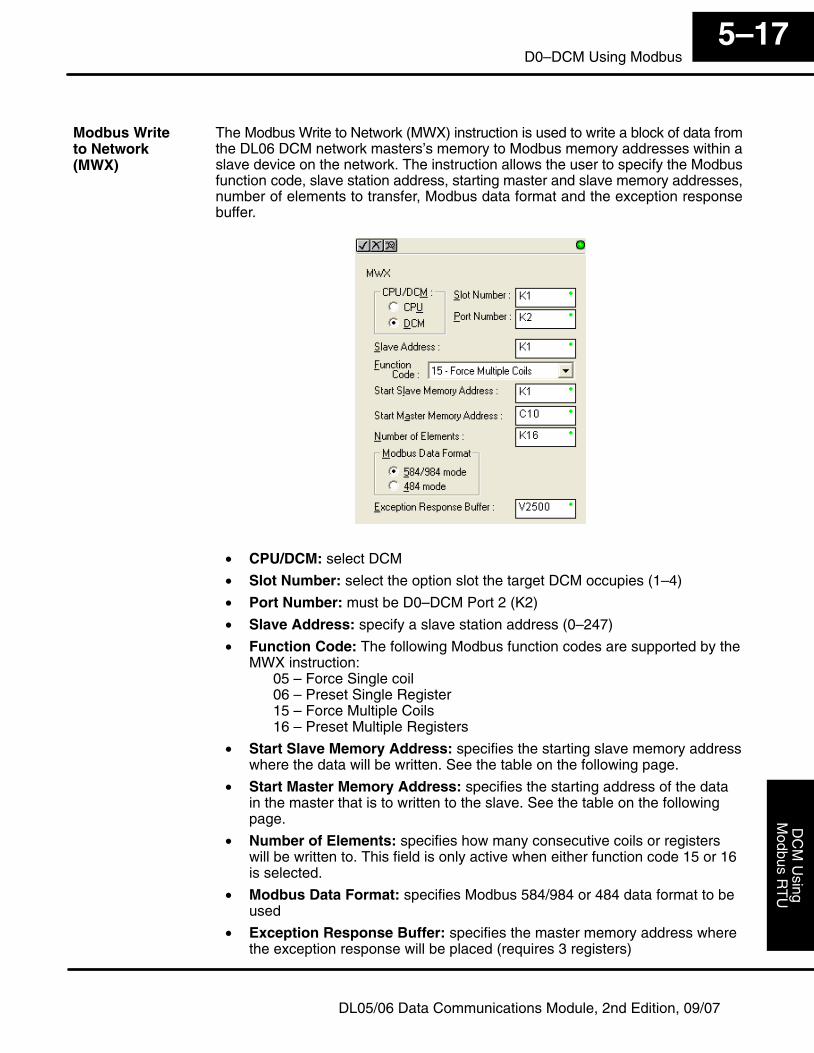
Modbus R
TU
DC
M U
singInstallation and
5–17D0–DCM Using Modbus
DL05/06 Data Communications Module, 2nd Edition, 09/07
The Modbus Write to Network (MWX) instruction is used to write a block of data fromthe DL06 DCM network masters’s memory to Modbus memory addresses within aslave device on the network. The instruction allows the user to specify the Modbusfunction code, slave station address, starting master and slave memory addresses,number of elements to transfer, Modbus data format and the exception responsebuffer.
• CPU/DCM: select DCM
• Slot Number: select the option slot the target DCM occupies (1–4)
• Port Number: must be D0–DCM Port 2 (K2)
• Slave Address: specify a slave station address (0–247)
• Function Code: The following Modbus function codes are supported by theMWX instruction:
05 – Force Single coil06 – Preset Single Register15 – Force Multiple Coils16 – Preset Multiple Registers
• Start Slave Memory Address: specifies the starting slave memory addresswhere the data will be written. See the table on the following page.
• Start Master Memory Address: specifies the starting address of the datain the master that is to written to the slave. See the table on the followingpage.
• Number of Elements: specifies how many consecutive coils or registerswill be written to. This field is only active when either function code 15 or 16is selected.
• Modbus Data Format: specifies Modbus 584/984 or 484 data format to beused
• Exception Response Buffer: specifies the master memory address wherethe exception response will be placed (requires 3 registers)
Modbus Write to Network (MWX)
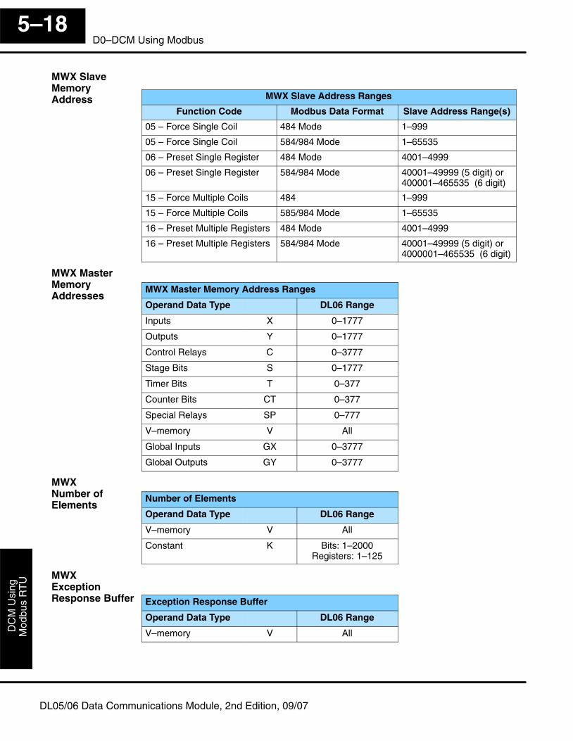
Mod
bus
RT
UD
CM
Usi
ng
5–18D0–DCM Using Modbus
DL05/06 Data Communications Module, 2nd Edition, 09/07
MWX Slave Address Ranges
Function Code Modbus Data Format Slave Address Range(s)
05 – Force Single Coil 484 Mode 1–999
05 – Force Single Coil 584/984 Mode 1–65535
06 – Preset Single Register 484 Mode 4001–4999
06 – Preset Single Register 584/984 Mode 40001–49999 (5 digit) or400001–465535 (6 digit)
15 – Force Multiple Coils 484 1–999
15 – Force Multiple Coils 585/984 Mode 1–65535
16 – Preset Multiple Registers 484 Mode 4001–4999
16 – Preset Multiple Registers 584/984 Mode 40001–49999 (5 digit) or4000001–465535 (6 digit)
MWX Master Memory Address Ranges
Operand Data Type DL06 Range
Inputs X 0–1777
Outputs Y 0–1777
Control Relays C 0–3777
Stage Bits S 0–1777
Timer Bits T 0–377
Counter Bits CT 0–377
Special Relays SP 0–777
V–memory V All
Global Inputs GX 0–3777
Global Outputs GY 0–3777
Number of Elements
Operand Data Type DL06 Range
V–memory V All
Constant K Bits: 1–2000Registers: 1–125
Exception Response Buffer
Operand Data Type DL06 Range
V–memory V All
MWX Slave Memory Address
MWX MasterMemory Addresses
MWX Number ofElements
MWX ExceptionResponse Buffer
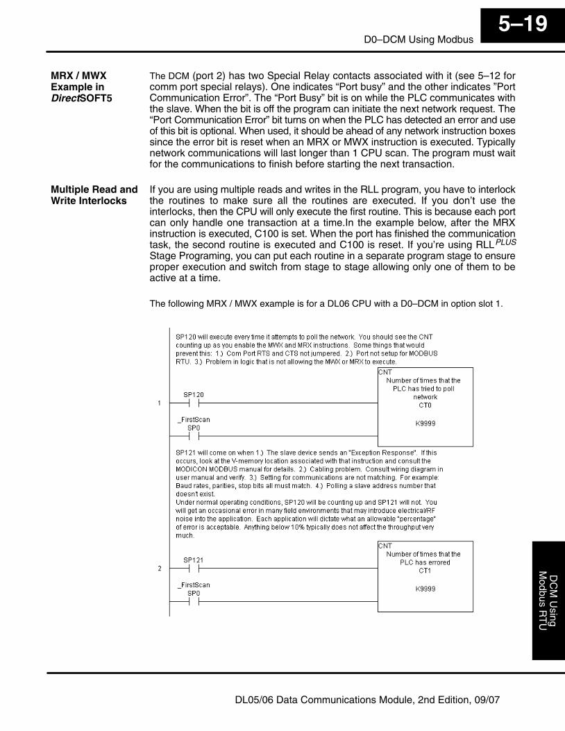
Modbus R
TU
DC
M U
singInstallation and
5–19D0–DCM Using Modbus
DL05/06 Data Communications Module, 2nd Edition, 09/07
The DCM (port 2) has two Special Relay contacts associated with it (see 5–12 forcomm port special relays). One indicates “Port busy” and the other indicates ”PortCommunication Error”. The “Port Busy” bit is on while the PLC communicates withthe slave. When the bit is off the program can initiate the next network request. The“Port Communication Error” bit turns on when the PLC has detected an error and useof this bit is optional. When used, it should be ahead of any network instruction boxessince the error bit is reset when an MRX or MWX instruction is executed. Typicallynetwork communications will last longer than 1 CPU scan. The program must waitfor the communications to finish before starting the next transaction.
If you are using multiple reads and writes in the RLL program, you have to interlockthe routines to make sure all the routines are executed. If you don’t use theinterlocks, then the CPU will only execute the first routine. This is because each portcan only handle one transaction at a time.In the example below, after the MRXinstruction is executed, C100 is set. When the port has finished the communicationtask, the second routine is executed and C100 is reset. If you’re using RLLPLUS
Stage Programing, you can put each routine in a separate program stage to ensureproper execution and switch from stage to stage allowing only one of them to beactive at a time.
The following MRX / MWX example is for a DL06 CPU with a D0–DCM in option slot 1.
MRX / MWXExample inDirectSOFT5
Multiple Read andWrite Interlocks
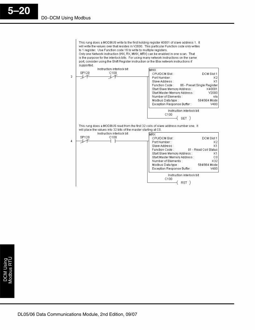
Mod
bus
RT
UD
CM
Usi
ng
5–20D0–DCM Using Modbus
DL05/06 Data Communications Module, 2nd Edition, 09/07
Communications Using Network IBoxInstructions
6
— NETCFG Network Configuration Instruction— NETRX Network Read Instruction— NETWX Network Write Instruction
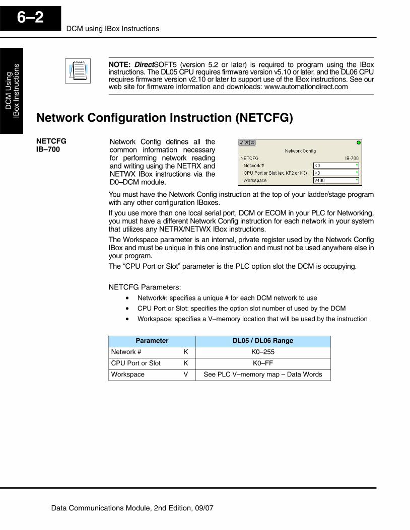
DC
M U
sing
IBox
Inst
ruct
ions
6–2DCM using IBox Instructions
Data Communications Module, 2nd Edition, 09/07
NOTE: DirectSOFT5 (version 5.2 or later) is required to program using the IBoxinstructions. The DL05 CPU requires firmware version v5.10 or later, and the DL06 CPUrequires firmware version v2.10 or later to support use of the IBox instructions. See ourweb site for firmware information and downloads: www.automationdirect.com
Network Configuration Instruction (NETCFG)
Network Config defines all thecommon information necessaryfor performing network readingand writing using the NETRX andNETWX IBox instructions via theD0–DCM module.
You must have the Network Config instruction at the top of your ladder/stage programwith any other configuration IBoxes.If you use more than one local serial port, DCM or ECOM in your PLC for Networking,you must have a different Network Config instruction for each network in your systemthat utilizes any NETRX/NETWX IBox instructions.The Workspace parameter is an internal, private register used by the Network ConfigIBox and must be unique in this one instruction and must not be used anywhere else inyour program.The “CPU Port or Slot” parameter is the PLC option slot the DCM is occupying.
NETCFG Parameters:• Network#: specifies a unique # for each DCM network to use
• CPU Port or Slot: specifies the option slot number of used by the DCM
• Workspace: specifies a V–memory location that will be used by the instruction
Parameter DL05 / DL06 Range
Network # K K0–255
CPU Port or Slot K K0–FF
Workspace V See PLC V–memory map – Data Words
NETCFGIB–700
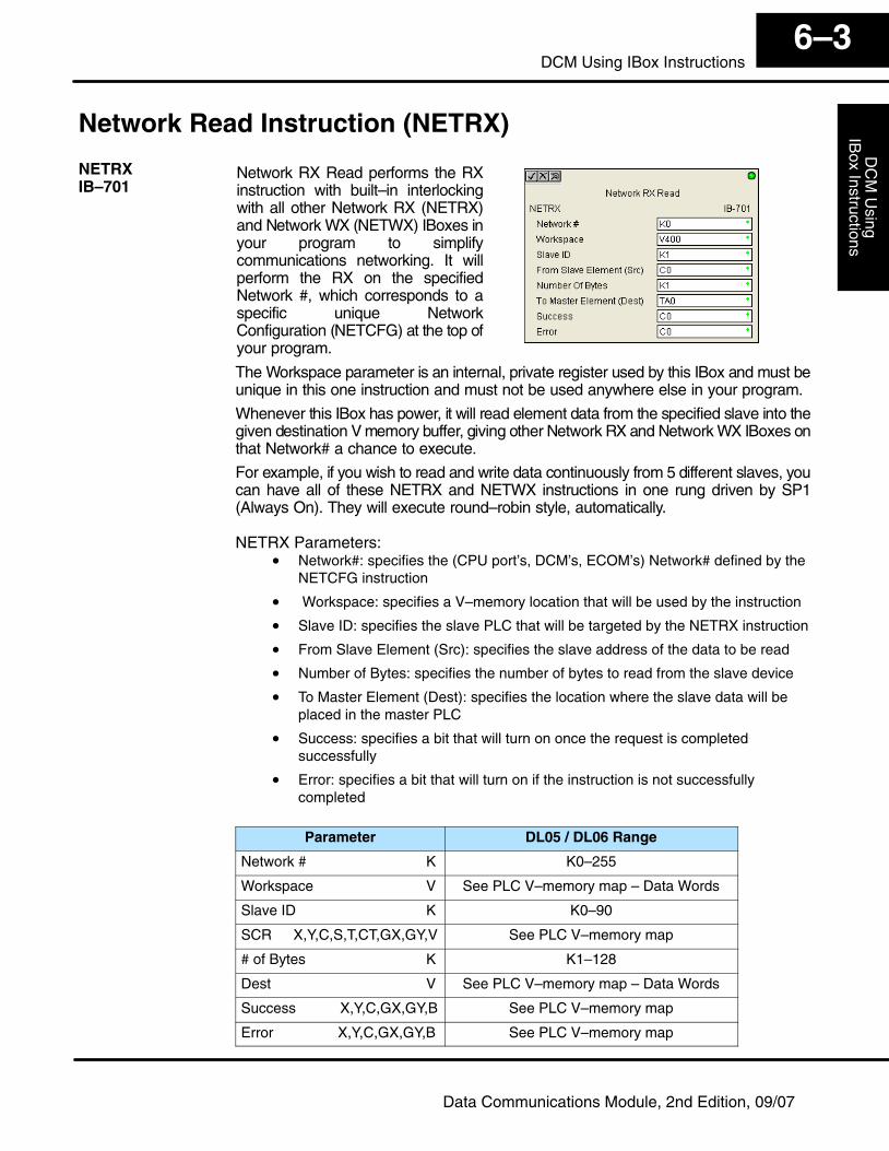
DC
M U
singIB
ox Instructions6–3
DCM Using IBox Instructions
Data Communications Module, 2nd Edition, 09/07
Network Read Instruction (NETRX)
Network RX Read performs the RXinstruction with built–in interlockingwith all other Network RX (NETRX)and Network WX (NETWX) IBoxes inyour program to simplifycommunications networking. It willperform the RX on the specifiedNetwork #, which corresponds to aspecific unique NetworkConfiguration (NETCFG) at the top ofyour program.
The Workspace parameter is an internal, private register used by this IBox and must beunique in this one instruction and must not be used anywhere else in your program.
Whenever this IBox has power, it will read element data from the specified slave into thegiven destination V memory buffer, giving other Network RX and Network WX IBoxes onthat Network# a chance to execute.
For example, if you wish to read and write data continuously from 5 different slaves, youcan have all of these NETRX and NETWX instructions in one rung driven by SP1(Always On). They will execute round–robin style, automatically.
NETRX Parameters:• Network#: specifies the (CPU port’s, DCM’s, ECOM’s) Network# defined by the
NETCFG instruction
• Workspace: specifies a V–memory location that will be used by the instruction
• Slave ID: specifies the slave PLC that will be targeted by the NETRX instruction
• From Slave Element (Src): specifies the slave address of the data to be read
• Number of Bytes: specifies the number of bytes to read from the slave device
• To Master Element (Dest): specifies the location where the slave data will beplaced in the master PLC
• Success: specifies a bit that will turn on once the request is completedsuccessfully
• Error: specifies a bit that will turn on if the instruction is not successfullycompleted
Parameter DL05 / DL06 Range
Network # K K0–255
Workspace V See PLC V–memory map – Data Words
Slave ID K K0–90
SCR X,Y,C,S,T,CT,GX,GY,V See PLC V–memory map
# of Bytes K K1–128
Dest V See PLC V–memory map – Data Words
Success X,Y,C,GX,GY,B See PLC V–memory map
Error X,Y,C,GX,GY,B See PLC V–memory map
NETRXIB–701
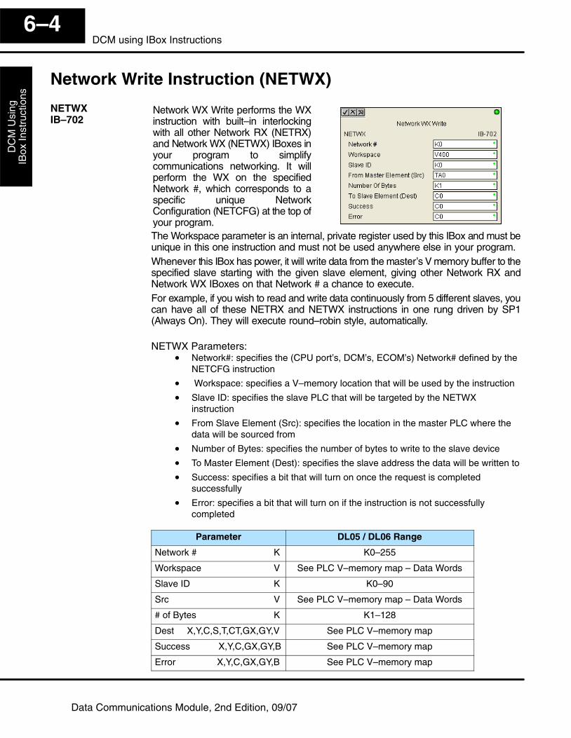
DC
M U
sing
IBox
Inst
ruct
ions
6–4DCM using IBox Instructions
Data Communications Module, 2nd Edition, 09/07
Network Write Instruction (NETWX)
Network WX Write performs the WXinstruction with built–in interlockingwith all other Network RX (NETRX)and Network WX (NETWX) IBoxes inyour program to simplifycommunications networking. It willperform the WX on the specifiedNetwork #, which corresponds to aspecific unique NetworkConfiguration (NETCFG) at the top ofyour program.The Workspace parameter is an internal, private register used by this IBox and must beunique in this one instruction and must not be used anywhere else in your program.Whenever this IBox has power, it will write data from the master’s V memory buffer to thespecified slave starting with the given slave element, giving other Network RX andNetwork WX IBoxes on that Network # a chance to execute.For example, if you wish to read and write data continuously from 5 different slaves, youcan have all of these NETRX and NETWX instructions in one rung driven by SP1(Always On). They will execute round–robin style, automatically.
NETWX Parameters:• Network#: specifies the (CPU port’s, DCM’s, ECOM’s) Network# defined by the
NETCFG instruction
• Workspace: specifies a V–memory location that will be used by the instruction
• Slave ID: specifies the slave PLC that will be targeted by the NETWXinstruction
• From Slave Element (Src): specifies the location in the master PLC where thedata will be sourced from
• Number of Bytes: specifies the number of bytes to write to the slave device
• To Master Element (Dest): specifies the slave address the data will be written to
• Success: specifies a bit that will turn on once the request is completedsuccessfully
• Error: specifies a bit that will turn on if the instruction is not successfullycompleted
Parameter DL05 / DL06 Range
Network # K K0–255
Workspace V See PLC V–memory map – Data Words
Slave ID K K0–90
Src V See PLC V–memory map – Data Words
# of Bytes K K1–128
Dest X,Y,C,S,T,CT,GX,GY,V See PLC V–memory map
Success X,Y,C,GX,GY,B See PLC V–memory map
Error X,Y,C,GX,GY,B See PLC V–memory map
NETWXIB–702
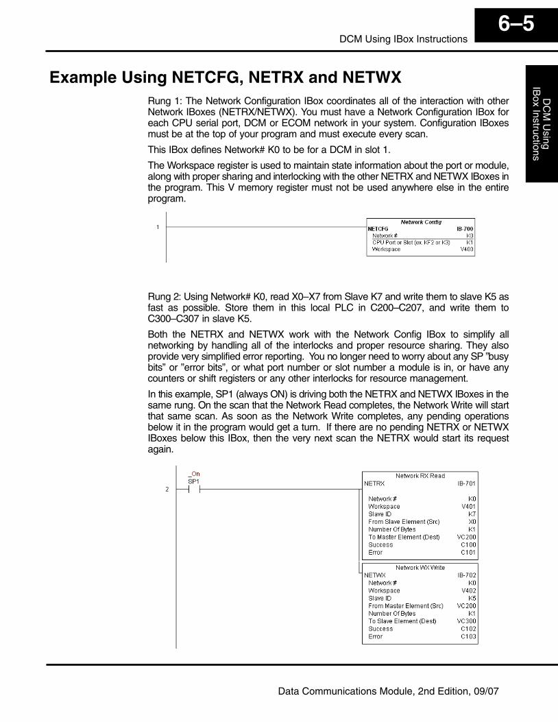
DC
M U
singIB
ox Instructions6–5
DCM Using IBox Instructions
Data Communications Module, 2nd Edition, 09/07
Example Using NETCFG, NETRX and NETWXRung 1: The Network Configuration IBox coordinates all of the interaction with otherNetwork IBoxes (NETRX/NETWX). You must have a Network Configuration IBox foreach CPU serial port, DCM or ECOM network in your system. Configuration IBoxesmust be at the top of your program and must execute every scan.
This IBox defines Network# K0 to be for a DCM in slot 1.
The Workspace register is used to maintain state information about the port or module,along with proper sharing and interlocking with the other NETRX and NETWX IBoxes inthe program. This V memory register must not be used anywhere else in the entireprogram.
Rung 2: Using Network# K0, read X0–X7 from Slave K7 and write them to slave K5 asfast as possible. Store them in this local PLC in C200–C207, and write them toC300–C307 in slave K5.
Both the NETRX and NETWX work with the Network Config IBox to simplify allnetworking by handling all of the interlocks and proper resource sharing. They alsoprovide very simplified error reporting. You no longer need to worry about any SP ”busybits” or ”error bits”, or what port number or slot number a module is in, or have anycounters or shift registers or any other interlocks for resource management.
In this example, SP1 (always ON) is driving both the NETRX and NETWX IBoxes in thesame rung. On the scan that the Network Read completes, the Network Write will startthat same scan. As soon as the Network Write completes, any pending operationsbelow it in the program would get a turn. If there are no pending NETRX or NETWXIBoxes below this IBox, then the very next scan the NETRX would start its requestagain.