Embed Size (px)
Citation preview

H2020 5G-TRANSFORMER Project
Grant No. 761536
Final design and implementation report on the MTP (report)
Abstract
This deliverable provides the final version of the Mobile Transport and Computing
Platform (5GT-MTP) design addressing the following aspects: the final architecture of
the 5GT-MTP; updates on 5GT-MTP interfaces towards the service orchestrator (5GT-
SO); the final workflows between the 5GT-SO and the 5GT-MTP as well as workflows
among the various components of the 5GT-MTP.

Definition of the Mobile Transport and Computing Platform (report) 2
H2020-761536
Document properties
Document number D2.3
Document title Final design and implementation report on the MTP (report)
Document responsible Paola Iovanna (TEI)
Document editor Teresa Pepe (TEI)
Editorial team Paola Iovanna (TEI), Teresa Pepe (TEI)
Target dissemination level Public
Status of the document Final
Version 1.0
Production properties
Reviewers Cao-Thanh Phan (BCOM), Charles Turyagyenda (IDCC), Luca Valcarenghi (SSSA), Carlos Guimarães (UC3M), Ricardo Martínez (CTTC), Andres Garcia-Saavedra (NECLE), Carlos J. Bernardos (UC3M)
Disclaimer
This document has been produced in the context of the 5G-TRANSFORMER Project.
The research leading to these results has received funding from the European
Community's H2020 Programme under grant agreement Nº H2020-761536.
All information in this document is provided “as is" and no guarantee or warranty is given
that the information is fit for any particular purpose. The user thereof uses the information
at its sole risk and liability.
For the avoidance of all doubts, the European Commission has no liability in respect of
this document, which is merely representing the authors view.

Definition of the Mobile Transport and Computing Platform (report) 3
H2020-761536
1 Table of Contents List of Contributors ........................................................................................................ 5
List of Figures ............................................................................................................... 6
List of Tables ................................................................................................................ 9
List of Acronyms ......................................................................................................... 10
Executive Summary and Key Contributions ................................................................ 12
1 Introduction .......................................................................................................... 13
2 Updates of Mobile Transport Platform architecture .............................................. 14
2.1 5GT-MTP architecture overview ................................................................... 14
2.2 5GT-MTP features ........................................................................................ 14
2.3 5GT-MTP functional components ................................................................. 15
2.4 5GT-MTP interfaces ..................................................................................... 16
2.5 Updates towards 5GT-MTP workflow ............................................................ 16
2.6 Updates towards the 5GT-MTP software implementation ............................. 16
3 Conclusions ......................................................................................................... 17
4 References .......................................................................................................... 18
5 Annex I: 5GT-MTP Design and Implementation ................................................... 20
5.1 Requirements on the 5GT-MTP .................................................................... 20
5.1.1 Discovery ............................................................................................... 21
5.1.2 Fulfilment ............................................................................................... 21
5.1.3 Assurance ............................................................................................. 22
5.1.4 Decommissioning .................................................................................. 22
5.2 5GT-MTP final architecture ........................................................................... 23
5.3 5GT-MTP features ........................................................................................ 24
5.3.1 Abstraction and information model ......................................................... 24
5.3.2 Slicing in the RAN .................................................................................. 32
5.3.3 Monitoring .............................................................................................. 44
5.3.4 Optimization algorithms ......................................................................... 46
5.4 5GT-MTP functional components detailed overview ..................................... 64
5.4.1 Abstraction Engine................................................................................. 64
5.4.2 Dispatcher ............................................................................................. 65
5.4.3 ResOrch ................................................................................................ 65
5.4.4 DB ......................................................................................................... 65
5.4.5 Local PA ................................................................................................ 65
5.4.6 Monitoring driver .................................................................................... 65
5.5 5GT-MTP interfaces ..................................................................................... 66

Definition of the Mobile Transport and Computing Platform (report) 4
H2020-761536
5.5.1 5GT-MTP NBI (5GT-SO SBI) ................................................................. 66
5.5.2 5GT-MTP SBI ........................................................................................ 83
5.5.3 MEC SBI ................................................................................................ 96
5.5.4 5GT-MTP monitoring interface ............................................................... 98
5.5.5 5GT-MTP placement interface ............................................................... 99
5.6 5GT-MTP workflow descriptions ................................................................. 103
5.6.1 Non-nested network service instantiation ............................................. 103
5.6.2 Non-nested network service termination .............................................. 107

Definition of the Mobile Transport and Computing Platform (report) 5
H2020-761536
List of Contributors Partner Short Name Contributors
TEI Paola Iovanna, Teresa Pepe, Fabio Ubaldi, Giuseppe Imbarlina
NECLE Andres Garcia Saavedra, Xi Li
NOK-N Dereje Kifle, Thomas Deiss, Bertold Dickhaus
NXW Marco Capitani, Giada Landi
MIRANTIS Oleksii Kolodiazhnyi
CTTC Ricardo Martínez, Jordi Baranda, Luca Vettori, Josep Mangues, Javier Vilchez, Laia Nadal
POLITO Claudio Casetti, Carla Fabiana Chiasserini, Christian Vitale
EURECOM Adlen Ksentini, Pantelis Frangoudis
SSSA Luca Valcarenghi, Nicola Sambo, Andrea Sgambelluri, Koteswararao Kondepu
UC3M Winnie Nakimuli

Definition of the Mobile Transport and Computing Platform (report) 6
H2020-761536
List of Figures Figure 1: Updates on 5GT-MTP architecture ............................................................... 14
Figure 2: 5GT-MTP final Architecture .......................................................................... 23
Figure 3: Physical infrastructure - abstraction model 1 ................................................ 25
Figure 4: Abstraction model 2 ..................................................................................... 26
Figure 5: Abstraction model 3 ..................................................................................... 26
Figure 6: Cross-abstraction for mobility support .......................................................... 28
Figure 7: 5GT-MTP view ............................................................................................. 30
Figure 8: 5GT-SO view of the coverage area .............................................................. 30
Figure 9: MEC regional abstraction ............................................................................. 31
Figure 10: NG-RAN architecture and functional split ................................................... 33
Figure 11: NSI implementation with dedicated and shared (V)NFs .............................. 35
Figure 12: Slice coverage and Tracking area mapping ................................................ 36
Figure 13: 5Q QoS framework and Qos flow mapping within slice .............................. 37
Figure 14: S-NSSAI to NSI mapping ........................................................................... 38
Figure 15: Multiplexed slice and mixed numerology support ....................................... 41
Figure 16: Example of multiple WANs (WIMs) to validate the proposed 5GT-MTP LL-PA
................................................................................................................................... 47
Figure 17: REST LL-PA API executing the LL-PA ....................................................... 48
Figure 18: Optimization problem for VNF placement within a single NFVI-PoP server 49
Figure 19: Heuristics for VNF placement ..................................................................... 51
Figure 20: Power consumption yielded by the heuristic algorithm vs. the optimum...... 52
Figure 21: Number of servers used by the heuristic algorithm vs. the optimum ........... 52
Figure 22: Unused vCPUs left by the heuristic algorithm vs. the optimum ................... 52
Figure 23: Bandwidth and latency requirements of main splits; function 𝐟𝟐 requires 𝐟𝟏,
and placement of 𝐟𝟑, 𝐟𝟎 is fixed; 𝛌 is the traffic ............................................................ 54
Figure 24 (a)-(c): Three actual RANs in Europe: red dots indicate the RUs’ locations;
black dots the routers/switches; and green dot the CU. ............................................... 58
Figure 25: Ratio of RAN centralized functions in swiss, romanian and italian topologies
for different values of CU capacity and traffic load ...................................................... 59
Figure 26: Number of Benders iterations in Swiss, Romanian and Italian .................... 59
Figure 27: RAN centralization (top) and system cost (bottom) for Italian topology (R3) for
𝜶𝒏 = 𝜶𝟎 = 𝟏 and variable transport costs, for C-RAN, D-RAN and FluidRAN
architectures ............................................................................................................... 60
Figure 28: RAN centralization (top) and cost (bottom) for different MEC process
characteristics and loads. Non-MEC load is 10 Mb/s for all RUs ................................. 61
Figure 29: Two-step recovery scheme architecture ...................................................... 62
Figure 30: Overall rate recovered through format adaptation at: (a) varying the offered
traffic load with 2-dB-OSNR-penalty soft failures; (b) the OSNR penalty with 100 Erlang
of traffic load................................................................................................................ 63
Figure 31: (a) Scenario considered for the experimental evaluation; (b) Capture (at the
UE) of ICMP messages exchanged between the EPC and the UE ............................. 64
Figure 32: Cloud/network view at the 5gt-so: NFVI-PoPs and logical Links (LLs) ........ 67
Figure 33: Request/Response 5GT-MTP NBI for retrieval of cloud and network
information .................................................................................................................. 67
Figure 34: 5GT-MTP NBI: get method with NFVI-PoP array information ..................... 69
Figure 35: Example of the identifiers and addressing of a unidirectional LL ................ 70
Figure 36: 5GT-MTP NBI: get method with logicalLinkInterNfviPoparray information .. 71

Definition of the Mobile Transport and Computing Platform (report) 7
H2020-761536
Figure 37: Request/Response 5GT-MTP NBI for allocating resources on a set of LLs
selected by the 5GT-SO PA ........................................................................................ 72
Figure 38: 5GT-MTP NBI: request message body for allocating a set of LLs for a given
network service (serviceId) ......................................................................................... 73
Figure 39: 5GT-MTP NBI: response message body for allocating a set of LLs for a given
network service (serviceId) ......................................................................................... 74
Figure 40: Request/Response 5GT-MTP NBI for removing the inter-NFVI-PoP resources
related to a specific serviceId ...................................................................................... 74
Figure 41: 5GT-MTP NBI: request message body for de-allocating all network resources
associated to a given serviceId ................................................................................... 75
Figure 42: Request/Response 5GT-MTP NBI for creating the intra-NFVI-PoP
connectivity ................................................................................................................. 76
Figure 43: Request/Response for allocation compute resources ................................. 77
Figure 44: Example of the compute allocation request body ....................................... 78
Figure 45: Example of the compute allocation response body ..................................... 80
Figure 46: Request/Response for terminating compute resources .............................. 82
Figure 47: Request/Response 5GT-MTP SBI for retrieval of NFVI-PoPs information .. 84
Figure 48: Get method with nfvi-PoPs information ...................................................... 84
Figure 49: Request/Response 5GT-MTP SBI for retrieval of resource zones information
................................................................................................................................... 85
Figure 50: Get method with resource zones information ............................................. 85
Figure 51: Request/Response 5GT-MTP SBI for retrieval of virtualised compute
resources information ................................................................................................. 86
Figure 52: Get method with virtualised compute resources information ....................... 87
Figure 53: Request/Response 5GT-MTP SBI for retrieval of compute capacity
information .................................................................................................................. 88
Figure 54: Get method with compute capacity information .......................................... 88
Figure 55: Request/Response 5GT-MTP SBI for instantiation of a VNF ...................... 89
Figure 56: Request/Response 5GT-MTP SBI for termination of a VNF ....................... 89
Figure 57: Request/Response 5GT-MTP SBI for instantiation of an intra-PoP connectivity
................................................................................................................................... 90
Figure 58: Request/Response 5GT-MTP SBI for termination of an intra-PoP connectivity
................................................................................................................................... 90
Figure 59: Request/Response 5GT-MTP SBI for retrieval of WAN aggregated resources
information .................................................................................................................. 92
Figure 60: Get method with WAN aggregated resources information .......................... 92
Figure 61: Request/Response 5GT-MTP SBI for instantiation of WAN network resource
................................................................................................................................... 94
Figure 62: Post method input parameters ................................................................... 95
Figure 63: Post method output parameters ................................................................. 95
Figure 64: Request/Response 5GT-MTP SBI for termination of WAN network resource
................................................................................................................................... 95
Figure 65: Available MEC plugin REST API calls ........................................................ 96
Figure 66: Example of a service creation request over the MEC plugin API. ............... 97
Figure 67: Interworking between the 5GT-MTP and the PAs using the defined API .... 99
Figure 68: 5GT-MTP view providing inter-NFVI-PoPs connectivity ............................ 100
Figure 69: 5GT-TMP PA API: request message body for requesting a network compute
route to a specific PA ................................................................................................ 102

Definition of the Mobile Transport and Computing Platform (report) 8
H2020-761536
Figure 70: 5GT-MTP PA API: response message body providing the compute path which
may encompass multiple WANs ................................................................................ 103
Figure 71: Logical link instantiation ........................................................................... 105
Figure 72: VNF instantiation ...................................................................................... 107
Figure 73: VNF termination workflow ........................................................................ 108
Figure 74: Logical link termination workflow .............................................................. 110

Definition of the Mobile Transport and Computing Platform (report) 9
H2020-761536
List of Tables Table 1: Requirements on the discovery phase........................................................... 21
Table 2: Requirements on the fulfilment phase ........................................................... 22
Table 3: Requirements on the assurance phase ......................................................... 22
Table 4: Requirements on the decommissioning phase .............................................. 23
Table 5: Information model of the logical link .............................................................. 26
Table 6: Information model of the compute resource................................................... 27
Table 7: Information model of the memory resource ................................................... 27
Table 8: Information model of the storage resource .................................................... 27
Table 9: Abstraction of the radio coverage area .......................................................... 29
Table 10: Abstraction model of the MEC specific parameters ..................................... 32
Table 11: Notations ..................................................................................................... 50

Definition of the Mobile Transport and Computing Platform (report) 10
H2020-761536
List of Acronyms Acronym Description
3G Third Generation
3GPP Third Generation Partnership Project
4G Fourth Generation
5G Fifth Generation
5GPPP 5G Infrastructure Public Private Partnership
5GT-MTP Mobile Transport and Computing Platform 5GT-SO Service Orchestrator
5GT-VS Vertical Slicer
AMF Access and Mobility Function
API Application Programming Interface
AS Application Server
CN Core Network
CU Centralized Unit
CPRI Common Public Radio Interface
CPU Central Processing Unit
DB Database
DC Data Centre
DU Distributed Unit DNS Domain Name System
E2E End to End
eNodeB, eNB Evolved Node B
EPC Evolved Packet Core
ETSI European Telecommunication Standardization Institute
gNB Next Generation Node B
IM Infrastructure Manager
IoT Internet of Things
KPI Key Performance Indicator
LL Logical Link
LPA Local PA
LTE Long Term Evolution MEC Multi-access Edge Computing
MEO Multi-access Edge Orchestrator
MEP Multi-access Edge Platform
MEPM MEC Platform Manager
MIMO Multiple Input Multiple Output
MME Mobility Management Entity
MNO Mobile Network Operator
MVNO Mobile Virtual Network Operator NBI Northbound Interface
NF Network Function
NFV Network Function Virtualization
NFVI Network functions virtualization infrastructure
NFV-NS NFV Network Service
NFV-NSO Network Service Orchestrator
NFVO NFV Orchestrator
NFVO-RO Resource Orchestrator
NG-RAN Next Generation RAN
NRT Non Real Time
NSD Network Service Descriptor

Definition of the Mobile Transport and Computing Platform (report) 11
H2020-761536
NSI Network Slice Instance
NSSI Network Slice Subnet Instances
OLE On site Live Event Experience
OSNR Optical Signal to Noise Ratio
OSS Operating Support System
PA Placement Algorithm PDU Protocol Data Unit
PM Performance Monitoring
PNF Physical Network Function
PNFM PNF Manager
PoP Point of Presence
QoS Quality of Service
RAM Random Access Memory
RAN Radio Access Network
ResOrch Resource Orchestration
REST Representational State Transfer
RNIS Radio Network Information Service
RRM Radio Resource Management RT Real Time
RU Radio Unit
SIB System Information Blocks
SBI Southbound Interface
SDN Software Defined Networking
SLA Service Level Agreement
SLPOC Single Logical Point of Contact
SMS Short Messaging Service
S-NSSAI Single Network Slice Selection Assistance Information
TA Tracking Area
TAI Tracking Area Identifier
TD Technology Domain
TN Transport Network
UPF User Plane Function
vCPU Virtual CPU
VIM Virtual Infrastructure Manager LL Logical Link
LLD Logical Link Descriptor
VM Virtual Machine
VNF Virtual Network Function
WIM Wide area network Infrastructure Manager
Definition of the Mobile Transport and Computing Platform (report) 12
H2020-761536
Executive Summary and Key Contributions This deliverable reports the final release (R2) of the Mobile Transport and Computing
Platform (5GT-MTP), highlighting updates on the 5GT-MTP architecture with respect to
the initial architecture presented in D2.1 [1].
The novelties introduced has the aim to improve the 5GT-MTP architecture presented in
the first release providing new features and functionalities that takes into account the
feedback received by the Proof of Concept (PoC) to simultaneously support the needs
of different vertical industries (such as, eHealth, automotive, entertainment, eIndustry
and MNVO).
In more details, the main updates reported in this deliverable are related to:
• 5GT-MTP features: new features have been added to support Radio and MEC
infrastructures, resource Monitoring and Local Placement Algorithm.
• 5GT-MTP functional components: two new modules have been introduced, the
Local PA, and the Monitoring Driver to provide resource optimization and manage
the communication with the Prometheus monitoring platform adopted in the
project, respectively. Moreover, the already existing modules have been
extended to support the new features introduced in R2. In particular, the
Abstraction Engine, the ResOrch and the DB have been extended to take into
account also Radio and MEC resource domains; the Dispatcher has been
extended to support also the Monitoring Driver and Local PA module.
• 5GT-MTP interfaces: interfaces have been updated to allows the instantiation of
MEC and Radio Application and to handle the communication with the monitoring
platform and the PA algorithms;
• Workflows: changes have been done to the workflows to take into account the
interaction with Radio and MEC domains.
For an easy reading of the deliverable, the document has been divided into two parts.
The first part, presented in the main body of the document, reports the summary of the
updates on the initial design of the 5GT-MTP platform. The second part, instead, reports
a full self-contained description of the 5GT platform.
Details on software implementation are reported in D2.4 [4].

Definition of the Mobile Transport and Computing Platform (report) 13
H2020-761536
1 Introduction The aim of 5G-TRANSFORMER is to deliver a complete scalable 5GT-MTP design and
implementation to handle infrastructure manager’s resources while supporting integrated
MEC and radio services, new abstraction models (with also mobility support) and
dynamic local placement of virtual functions.
The 5GT-MTP is responsible for the orchestration of resources and the instantiation of
VNFs over the infrastructure under its control, as well as of managing the underlying
physical mobile transport network, computing and storage infrastructure. In a nutshell, it
manages all the infrastructures as a Single Logic Point of Contact (SLPOC), providing a
common abstraction view of the managed resources to the 5GT-SO.
While, in the first phase, the project focused on transport (WIM) and data-center (VIM)
resource controllers, in the second phase the abstraction and the resource management
have been extended by supporting also both RAN and MEC resource infrastructures.
The objective of this deliverable is to provide the final version of the 5GT-MTP design
highlighting the updates introduced in Release 2 (R2) with respect to the previous release
described in D2.1 [1]. The main updates are related to: i) features, ii) functional
components, iii) 5GT-MTP interfaces and iv) supported workflows (among the different
building blocks and 5GT architecture elements.
In order to keep the main body of the document as short as possible, the deliverable is
divided into two parts:
- The main body: it focuses only on a summary of the updates towards the 5GT-
MTP final architecture introduced in the second release.
- Annex I: it reports and details a self-contained description of the 5GT-MTP.
In more details, the deliverable reports the updates towards the 5GT-MTP final
architecture in Section 2, describing the extension to the 5GT-MTP architecture in terms
of new features, functional components and related interfaces This section also shows
updates on 5GT-MTP workflows, and reports a short description of the updates on the
software implementation. The main body of the deliverable is concluded in Section 3.
The complete description of the updates on the 5GT-MTP platform is reported in the
Annex I. For a better reading of the deliverable, the Annex maintains the same structure
of the main body.

Definition of the Mobile Transport and Computing Platform (report) 14
H2020-761536
2 Updates of Mobile Transport Platform architecture
2.1 5GT-MTP architecture overview
The 5GT-MTP architecture is aligned with the initial architecture presented in D2.1 [1].
However, additional functional components and related interfaces to provide new or
enhanced features have been added to cover the targeted use cases requirements (e.g.,
MEC and Radio support) [5] or to take into account feedback from the PoC.
FIGURE 1: UPDATES ON 5GT-MTP ARCHITECTURE
Figure 1 shows the final 5GT-MTP architecture highlighting in blue the major updates
with respect to the Release 1 (R1) ([1], [2]).
Moreover, minor changes have been also applied to other components, e.g., the
Abstraction engine, as reported in Section 2.2.
As shown in the Figure 1, the architecture still maintains the structure proposed in R1
acting as a single point of contact for the 5GT-SO. It provides the suitable abstract view
of the physical resources and orchestrate resources selecting and configuring transport,
Radio, MEC and DC resources compliant with the request from the 5GT-SO.
A description of the novel functional blocks is reported in Section 2.3 and in more detail
in Section 5.4.
2.2 5GT-MTP features
The second release (R2) of the 5GT-MTP platform introduces new features with respect
to the initial architecture specification, reported in D2.1 [1], and the first release (R1) of
the prototype, delivered in D2.2 [2].
In particular, the following features have been introduced:
- Radio and MEC support: this feature will extend the proposed abstraction method
in order to support both Radio and MEC domains/technologies.
- Network Slicing: this feature has been introduced to provide the required slicing
support in a scenario where heterogeneous technologies co-exist within the
transport network
- Resource Monitoring: this feature has been introduced to provide the monitoring
functionality of the infrastructure resources controlled by the 5GT-MTP.

Definition of the Mobile Transport and Computing Platform (report) 15
H2020-761536
- Local Placement Algorithm (PA): this feature provides resource optimization
inside an infrastructure manager domain.
More details of the mentioned features are provided in Annex I, i.e., Section 5.3.
2.3 5GT-MTP functional components
To support the new features covered in R2, new functional components have been
introduced and some extensions have been added to the existing ones (i.e., those
supported in R1).
A brief description of the functional components updates is reported below, for a
complete description, instead, please, refer to Annex I (i.e., Section 5.4):
- The Abstraction Engine has been extended to include both Radio and MEC
resource domains. The scope of the module is to provide an abstraction layer to
the upper software component of the general 5GT architecture (i.e. Service
Orchestration or 5GT-SO). The module considers a myriad of available resources
from transport (WIM), data-centers (VIM), RAN and MEC and provides a common
abstract view in terms of service parameters (e.g., bandwith, latency) that can be
guaranteed with the available resources.
- The Dispatcher is an Event bus that provides communication between the 5GT-
MTP modules using a publish-subscribe pattern. It allows all MTP modules to
post events that are handled by specific handlers. It has been extended to include
new events integrating the monitoring driver and the local Placement Algorithm
in the internal MTP workflow.
- The ResOrch module orchestrates the 5GT-MTP procedures among the
controlled domains (i.e., VIM, WIM). In R2 it has been extended to allows also the
orchestration of Radio and MEC domains. DB is a front-end that connects to an
external SQL server and handles all the queries (i.e., to insert entries, update
data and retrieve parameters) towards the database to store and retrieve
abstraction, aggregation and service information. It has been extended to store
and retrieve data about RAN and MEC managed resources.
- Local PA is a new module that provides the selection and optimization of
resources thanks to dedicated and specialized resource Placement Algorithm
(PA) algorithm. It handles the communication with an external PA module by
means of a new REST API. The aim of local PA module is two-fold. First, the local
PA module contacts an external PA module in order to get decision about the
specific VIM where to put a VNF in a multi-VIM domain. Second, the local PA
module may contact an external PA module to compute the interNfviPop
connectivity for a logical link between a pair of NFVI-PoP GWs with specific
network constraints.
- Monitoring Driver is a new functionality that manages the communication with the
monitoring platform of the 5G-T architecture (based on Prometheus) [11]. It uses
the monitoring interface exposed by the Monitoring Platform to register itself to
the platform, create performance monitoring jobs and get alert notifications.
Moreover, it handles notifications about the status of infrastructure resources
(i.e., compute, storage, networking, radio, and MEC resources) by posting
specific events to the dispatcher.

Definition of the Mobile Transport and Computing Platform (report) 16
H2020-761536
2.4 5GT-MTP interfaces
In R2, the MTP interfaces have been updated to support the new features and functional
components introduced.
The following updates have been introduced:
- MTP NBI to include the instantiation of MEC App and Radio functions (e.g.,
vEPC) to trigger monitoring jobs, allocate/terminate intra-NFVI-PoP connectivity
within the DC and explicitly start/stop the allocated VNF resources;
- MTP SBI to trigger on demand the allocation/termination of intra-NFVI-PoP
connectivity within the DC and start/stop allocated VNFs;
- MEC SBI is part of the MTP SBI and is used to enable the communication with
the MEC domain;
- MTP Monitoring Interface to handle the communication with the monitoring
platform;
- MTP Placement Algorithm (PA) interface to handle the communication with the
placement algorithms.
A detailed description of the 5GT-MTP interfaces is reported in the Section 5.5 of the
Annex I.
2.5 Updates towards 5GT-MTP workflow
To optimize the orchestration of infrastructure resources, in R2, the workflows presented
in D2.1 [1] are updated to include also the Radio and MEC domains. The updated
workflows, including MEC domain are described in Annex I of this deliverable in Section
5.6. Note that, since discussion on Radio is ongoing, the handling of Radio resources will
be described in D1.4.
2.6 Updates towards the 5GT-MTP software implementation
All the updates reported above have been deployed and implemented in R2. The
complete software implementation can be downloaded from GitHub [3]. A detailed
description of the reference software is reported in D2.4 [4].

Definition of the Mobile Transport and Computing Platform (report) 17
H2020-761536
3 Conclusions In this deliverable we have described the updates towards the final 5GT-MTP
architecture implementation, highlighting the novel features and functionalities being
adopted and considered.
We presented an updated version of D2.1 [1] that integrates and extensively discusses
these modifications within the overall architecture specification. This encompasses the
main updates related to extended features and functional components, 5GT-MTP
interfaces and workflows.
The changes/extensions introduced in the R2 aim to support also Radio and MEC
infrastructures to improve the features already supported in R1 that focused only on
transport and DC resources. Moreover, R2 provides resource Monitoring and Local
Placement Algorithm to optimise the resource usage.

Definition of the Mobile Transport and Computing Platform (report) 18
H2020-761536
4 References [1] 5G-TRANSFORMER, D2.1, Definition of the Mobile Transport and Computing
Platform, April 2018
[2] 5G-TRANSFORMER, D2.2, Initial MTP Reference Implementation, November 2018
[3] MTP Github repository available at https://github.com/5g-transformer/5gt-mtp.
[4] 5G-TRANSFORMER, D2.4, Final design and implementation report on the MTP, May
2019.
[5] 5G-TRANSFORMER, D5.2, Integration and proofs of concept plan, January 2019.
[6] 5G-TRANSFORMER, D1.1, Report on vertical requirements and use cases,
November 2017.
[7] 5G-TRANSFORMER, D1.2, 5G-TRANSFORMER initial system design, May 2018.
[8] 5G-TRANSFORMER, D1.3, 5G-TRANSFORMER Refined Architecture, May 2019.
[9] ETSI GS NFV-IFA 006, “Network Function Virtualisation (NFV); Release 2;
Management and Orchestration; Vi-Vnfm reference point – Interface and Information
Model Specification”, v2.4.1, February 2018.
[10] ETSI GS NFV-IFA 028, “Network Functions Virtualisation (NFV) Release 3;
Management and Orchestration; Report on architecture options to support multiple
administrative domains”, v3.1.1, January 2018.
[11] 5G-TRANSFORMER, D4.3, Final design and implementation report on service
orchestration, federation and monitoring platform, May 2019.
[12] 5G-TRANSFORMER, D1.3, 5G-TRANSFORMER Refined Architecture,May 2019.
[13] 3GPP TS38.401, V15.4.0, NG-RAN, Architecture Description, December 2018
[14] 3GPP TS38.300, V15.0.0, NR and NG-RAN Overall Description; Stage 2, December
2017.
[15] 3GPP TS23.501, V15.0.0, System Architecture for the 5G System; Stage 2, 2017
[16] GPP TS28.541, V15.1.0, 5G Network Resource Model (NRM); Stage 2 and stage 3,
April 2019.
[17] G-CrossHaul, D3.2: Final XFE/XCI design and specification of southbound and
northbound interfaces, November 2017
[18] Yen, Jin Y. "An algorithm for finding shortest routes from all source nodes to a given
destination in general networks". Quarterly of Applied Mathematics. 27 (4): 526–530.
1970Beloglazov, Anton, and Rajkumar Buyya. "Optimal online deterministic
algorithms and adaptive heuristics for energy and performance efficient dynamic
consolidation of virtual machines in cloud data centers." Concurrency and
Computation: Practice and Experience 24, no. 13 (2012): 1397-1420.
[19] B. Gavish, H. Pirkul, "Algorithms for the Multi-Resource Generalized Assignment
Problem," Management Science, Vol. 37, No. 6, 1991, pp. 695-713.
[20] Gavish, Bezalel, and Hasan Pirkul. "Algorithms for the multi-resource generalized
assignment problem." Management science 37, no. 6 (1991): 695-713.
[21] A. Garcia-Saavedra, X. Costa-Perez, D. J. Leith, George Iosifidis "FluidRAN:
Optimized vRAN/MEC Orchestration", in Proc. of IEEE INFOCOM 2018.
[22] C. Y. Yeoh et al., “Performance study of LTE experimental testbed using
OpenAirInterface,” in Proc. of ICACT 2016, Jan 2016, pp. 617–622.
[23] N. Nikaein, “Processing Radio Access Network Functions in the Cloud: Critical
Issues and Modeling”, in Proc. of ACM MCS, 2015.
Definition of the Mobile Transport and Computing Platform (report) 19
H2020-761536
[24] V. Suryaprakash, et al., “Are Heterogeneous Cloud-Based Radio Access Networks
Cost Effective?”, in IEEE JSAC, vol. 33, no. 10, 2015.
[25] P. Rost, et al., “The Complexity-Rate Tradeoff of Centralized Radio Access
Networks”, IEEE Trans. on Wireless Comm., 14 (11), 2015.
[26] N. Sambo et al., "Modeling and Distributed Provisioning in 10–40–100-Gb/s Multirate
Wavelength Switched Optical Networks," in Journal of Lightwave Technology, vol.
29, no. 9, pp. 1248-1257, May1, 2011.
[27] jGraphT available at https://jgrapht.org/
[28] EventBus Guava library available at https://github.com/google/guava
[29] ETSI GR NFV-IFA 022, Management and Orchestration; Report on Management
and Connectivity for Multi-Site Services”, v0.8.2, 2018.
[30] Prometheus monitoring platform available at https://prometheus.io/
[31] ETSI MEC 010-2, ”Mobile Edge Computing (MEC); Mobile Edge Management; Part
2: Application lifecycle, rules and requirements management”, v1.1.1, 2017
[32] MySQL relational database managfement system available at
https://www.mysql.com/
[33] ETSI GS NFV-IFA 005, “Network Function Virtualisation (NFV); Management and
Orchestration; Or-Vi reference point – Interface and Information Model Specification”,
v2.1.1, 2016
[34] ETSI GS MEC 003, ”Multi-access Edge Computing (MEC); Framework and
Reference Architecture,” V2.1.1, 2019.
[35] Swagger Online Editor, https://editor.swagger.io/

Definition of the Mobile Transport and Computing Platform (report) 20
H2020-761536
5 Annex I: 5GT-MTP Design and Implementation
5.1 Requirements on the 5GT-MTP
Technical requirements on the overall 5G-T system have been defined in D1.1 [6]. These
requirements focus on properties related to vertical services and relevant use cases.
General requirements related to the overall system are described in [7]. Additional
general requirements on the 5G-TRANSFORMER system, emerged during the
development of the project, are described in D1.3 [8]. In this section, we define the related
functional requirements specific to the 5GT-MTP updating the ones reported in D2.1 [1]
with new requirements, defined during the project, for the distinct phases referred before.
In this deliverable we follow – with slight adaptations – the notation for requirements used
already in [5][1]. For each requirement, the following fields should be provided:
ID Requirement F/NF
ReqX.XX e.g. The vehicle shall be connected to a 5G router F/NF
The meanings of the above fields are as follows:
• ID: is the identifier of the requirement (written in the form ReqX.XX).
• Requirement: a complete sentence explaining the requirement.
• F/NF: if the requirement is either Functional (F) or Non-Functional (NF).
NOTE: The requirement field is written according to the approach followed by IETF
documents using the keywords “must”, “must not”, “required”, “shall”, “shall not”, “should”,
“should not”, “recommended”, “may” and “optional”. In this document those terms
(keywords) are to be interpreted as described in [8].
1. MUST This word, or the terms “REQUIRED” or “SHALL”, mean that the definition
is an absolute requirement of the specification.
2. MUST NOT This phrase, or the phrase “SHALL NOT”, mean that the definition is
an absolute prohibition of the specification.
3. SHOULD This word, or the adjective “RECOMMENDED”, mean that there may
exist valid reasons in particular circumstances to ignore a particular item, but the
full implications must be understood and carefully weighted before choosing a
different course.
4. SHOULD NOT This phrase, or the phrase “NOT RECOMMENDED” mean that
there may exist valid reasons in particular circumstances when the particular
behavior is acceptable or even useful, but the full implications should be
understood and the case carefully weighed before implementing any behavior
described with this label.
5. MAY This word, or the adjective “OPTIONAL”, mean that an item is truly optional.
One vendor may choose to include the item because a particular marketplace
requires it or because the vendor feels that it enhances the product while another
vendor may omit the same item. An implementation which does not include a
particular option MUST be prepared to interoperate with another implementation
which does include the option, though perhaps with reduced functionality. In the
same vein, an implementation which does include a particular option MUST be

Definition of the Mobile Transport and Computing Platform (report) 21
H2020-761536
prepared to interoperate with another implementation which does not include the
option (except, of course, for the feature the option provides).
The 5GT-MTP is involved in the service lifecycle at different stages. Thus, different
requirements can be considered according to each stage, namely (1) Discovery, (2)
Fulfilment, (3) Assurance, and (4) Decommissioning.
5.1.1 Discovery
During the discovery phase, the 5GT-MTP exposes the underlying infrastructure,
following the appropriate abstraction levels, to the 5GT-SO. The following requirements
are identified:
TABLE 1: REQUIREMENTS ON THE DISCOVERY PHASE
ID Requirement F/NF
ReqMTP.Di.01 The 5GT-MTP shall store a catalog of NFVI-PoPs available
within the 5GT-MTP’s administrative domain, and related
resources (i.e., computing, storage, networking) in addition to
the available PNFs/VNFs.
F
ReqMTP.Di.02 The 5GT-MTP must provide the means to expose available
resources with the appropriate abstraction levels to 5GT-SO.
F
ReqMTP.Di.04 The 5GT-MTP shall keep up-to-date the catalog of related
NFVI components
F
ReqMTP.Di.06 The 5GT-MTP shall expose the current state of the available
PNFs.
F
ReqMTP.Di.07 The 5GT-MTP shall certify the credentials of entities
accessing its NFVI catalog.
F
ReqMTP.Di.08 The 5GT-MTP shall allow creating several instances of the
same VNF
F
ReqMTP.Di.09 The 5GT-MTP shall store a catalog containing the service
connection points along with some metadata, such as the
location, etc.
F
ReqMTP.Di.11 The 5GT-MTP must provide the 5GT-SO with the means to
send detailed resource allocation requests
F
ReqMTP.Di.12 The 5GT-MTP must provide the 5GT-SO with the means to
configure VNF instances
F
ReqMTP.Di.13 The 5G-MTP system should integrate diverse technological
environments such as RAN and MEC.
F
5.1.2 Fulfilment
During the service fulfilment phase, the 5GT-SO orchestrates (namely, creates and instantiates) network services requested by 5GT-VS, using the infrastructure abstraction provided by the 5GT-MTP. From the 5GT-MTP perspective this involves: appropriate configuration of the VNFs and PNFs, and allocation of resources in available NFVI-PoPs and their potential and required network (e.g., WAN) interconnectivity.

Definition of the Mobile Transport and Computing Platform (report) 22
H2020-761536
The following requirements are identified:
TABLE 2: REQUIREMENTS ON THE FULFILMENT PHASE
ID Requirement F/NF
ReqMTP.Fu.01 Depending on the modality of the contracted service, the
5GT-MTP may be required to offer proper configuration and
management interfaces to instantiated VNFs or requested
PNFs.
F
ReqMTP.Fu.02 The 5GT-MTP shall allow VNF scaling (up/down/in/out) F
ReqMTP.Fu.03 The 5GT-MTP shall allow resource scaling (up/down/in/out) F
ReqMTP.Fu.06 The 5GT-MTP shall certify the credentials of entities
accessing its NFVI.
F
ReqMTP.Fu.07 The 5G-MTP system should permit the extension of
connectivity among different NFVI-PoPs from multiple
providers at both intra- and inter-domain levels.
F
5.1.3 Assurance
The 5GT-MTP is responsible for guaranteeing the performance agreements requested
by the 5GT-SO via orchestrating the pool of needed VNFs as well as allocated resources
within NFVI-PoPs and PNFs. Additionally, sufficient monitoring information is needed to
keep track of ensuring the demanded 5GT-SO requirements on the demanded network
services. The following requirements are identified:
TABLE 3: REQUIREMENTS ON THE ASSURANCE PHASE
ID Requirement F/NF
ReqMTP.As.01 The 5GT-MTP must provide the 5GT-SO tools to monitor
the QoS attained to the instantiated VNFs, allocated PNFs
(and VLs) and their related resources.
F
ReqMTP.As.02 The 5GT-MTP shall certify the credentials of entities
accessing its NFVI monitoring information.
F
ReqMTP.As.04 The 5GT-MTP should be provide fault-tolerant
functionalities and report failure events upstream to the
5GT-SO as long as the 5GT-MTP is not able to recover /
restore the event failures impacting the service continuity.
F
ReqMTP.As.05 The 5G-MTP system must provide means for optimizing the
deployment of network services in terms of resources,
performance indicators.
F
5.1.4 Decommissioning
Once a service is decommissioned, the 5GT-MTP shall release the used resources and terminate the allocated VNFs as a response to the 5GT-SO termination operation. The following requirements are identified:

Definition of the Mobile Transport and Computing Platform (report) 23
H2020-761536
TABLE 4: REQUIREMENTS ON THE DECOMMISSIONING PHASE
ID Requirement F/NF
ReqMTP.De.01 The 5GT-MTP must be able to identify the allocated
resources for a VNF upon a VNF termination procedure
F
ReqMTP.De.02 The 5GT-MTP must be able to identify the monitoring
mechanisms to be de-activated as a result of a VNF
termination or resource deallocation
F
ReqMTP.De.03 The 5GT-MTP must be able to notify the 5GT-SO about
either VNFs or resources terminated
F
ReqMTP.De.04 The 5GT-MTP must restore the state of available PNFs
when its allocation is terminated
F
5.2 5GT-MTP final architecture
Figure 2 depicts the architecture of the 5GT-MTP with all the different components. From
the top-down view, the 5GT-MTP is based on the Single Logical Point of Contact
(SLPOC) architecture as defined in IFA028 [10], but implements additional features like
abstraction, monitoring and radio and MEC control. The 5GT-MTP SLPOC module
exposes abstracted resource view to the 5GT-SO ([11]) via the NBI. Moreover, it is
connected to different plugins: the transport WIM plugins, the VIM plugin, Radio plugin
and the MEC plugin. These plugins expose different (abstracted) resources view to the
5GT-MTP via the defined SBI. More details on WIM, VIM and Radio plugin are reported
in D2.2 [2]. MEC plugin instead is described in Section 5.5.3
FIGURE 2: 5GT-MTP FINAL ARCHITECTURE
5GT-MTP architecture consists in the following components and building blocks:
• Abstraction Engine: This module implements all algorithms and procedures
related to the abstraction. The “Domain Resource Logic” performs the
aggregation of the domain resources, while the “E2E Abstraction Logic” performs
the computation of the abstracted view. In the service allocation process, such
modules are also responsible to select the transport domain resources to allocate
for accommodating the required service.
Definition of the Mobile Transport and Computing Platform (report) 24
H2020-761536
• Database (DB): It is a common module that stores all the information and details
regarding the domain resource, the abstraction view and the services that are
allocated.
• Resource Orchestrator (ResOrch: It orchestrates the 5GT-MTP operations
between the VIM/Radio and Transport WIM/MEC domains.
• North-Bound Interface (NBI): It handles the IFA005 communication and
proprietary 5GT API for specific inter-NFVI-PoP connectivity purposes (based on
IFA005 principles and contents) with the 5GT-SO.
• South-Bound Interface (SBI): It handles the IFA005 communication with the
plugins.
• Dispatcher: It manages the inter-process communication between the 5GT-MTP
components (i.e., NBI, SBI, DB, RO, Abstraction Engine). The communications
use specific interfaces that each component exposes to the dispatcher.
• Local placement algorithm (Local PA): It takes decisions about where to put a
VNF in multi-VIM domains and select the transport resources for inter-NFVI-PoP
connectivity via an external PA module. The communication between the local
and external PA modules is done through a defined and proprietary 5GT REST
API.
• Monitoring driver: It is a module that communicates with the Monitoring Platform
[11]. It creates the performance monitoring (PM) jobs on the Monitoring Platform
and handles alert notifications from the Monitoring Platform.
5.3 5GT-MTP features
5.3.1 Abstraction and information model
Resource abstraction is a key element for the interworking between the 5GT-MTP and
the 5GT-SO. For this reason, the proposed abstraction models will meet the following
needs:
• keep the independency between the technology deployed in transport and radio,
and the information model to describe its resources so that the same information
model may be maintained even if the technology changes;
• guarantee a clear separation of tasks and responsibility, to facilitate, for instance,
fault locations;
• decouple the radio and transport solutions that can evolve to different releases
independently;
• associate radio and transport to different providers that can be combined to each
other in N:M relationship, where N and M are positive integers.
In the follows, we present the abstraction models for the different infrastructure
resources. In particular Section 5.3.1.1 presents the abstraction for transport and
compute resources; finally, how to support mobility and MEC application is reported in
Section 5.3.1.3 and Section 5.3.1.4, respectively.
5.3.1.1 Domain abstraction
The 5GT-MTP is responsible for providing the 5GT-SO with the information about the
available resources (including Radio, NFVI-PoP, transport and MEC), so that the 5GT-
SO can make decisions on service orchestration. Because of the varying level of trust
among organizations and the complexity associated to resource management, the 5GT-

Definition of the Mobile Transport and Computing Platform (report) 25
H2020-761536
MTP, in general, does not provide all its infrastructure details. Rather, it presents to the
5GT-SO the information with a certain level of abstraction.
Specifically, the resources managed by an 5GT-MTP can be divided into two groups:
computing resources and network resources (for Radio resources, please, refer to
Section 5.3.1.3). Computing resources are the physical machines (e.g., servers or
compute hosts) that can accommodate VNFs and are typically characterized by CPU,
memory, and storage resource capabilities. Computing resources are grouped
depending on the location in the NFVI-PoPs. The physical machines of an NFVI-PoP are
managed by the VIM. Network resources are represented by the network forwarding units
and the physical links interconnecting them. WIMs control the network resources
connecting different and remote NFVI-PoPs.
An infrastructure can thus be represented as a composition of network and computing
(including storage) resources controlled by WIMs and VIMs, respectively. Since the
nature of these resources is intrinsically different, the abstraction mechanisms for these
two types of resources are also different.
Three abstraction models have been defined:
1. 5GT-MTP exposes all physical resources (i.e., Radio, transport, storage
and computing) to the 5GT-SO.
2. 5GT-MTP exposes all the available cloud resources.
3. 5GT-MTP exposes aggregated cloud resources availability.
As said, the first model exposes all the physical resources (radio, transport, storage, and
computing) as shown in Figure 3.
FIGURE 3: PHYSICAL INFRASTRUCTURE - ABSTRACTION MODEL 1
In the abstraction model 2, the 5GT-MTP reports all details about computing resources
while the network resources are abstracted as a set of logical links connecting the NFVI-
PoPs (Figure 4).

Definition of the Mobile Transport and Computing Platform (report) 26
H2020-761536
FIGURE 4: ABSTRACTION MODEL 2
Finally, in the third abstraction model (Figure 5) also the computing resources are
abstracted. The 5GT-MTP reports the computing capabilities, CPUs, memory, storage,
with an NFVI-PoP granularity instead of by physical-machine granularity as in model 2.
Regarding the network resources, only the connections between NFVI-PoPs are
reported, i.e., logical links with a given bandwidth and latency.
FIGURE 5: ABSTRACTION MODEL 3
For models 2 and 3, for the network abstraction, two options are possible:
a. for MNO/MVNO service only transport resources are abstracted (using logical
links) instead the mobile resources are exposed. Radio and mobile function implemented
on generic processing (e.g., vEPC) will be exposed as DC resources.
b. for other verticals both transport and mobile resources are abstracted in logical
links.
5G-T has adopted and implemented the above described abstraction model 3.
5.3.1.2 Information models for compute, storage, and network resources
This subsection reports the information models to describe abstracted network, compute,
memory, and storage resources. Table 5 shows the information model of a logical link
with specific reference to the abstraction model 2. An abstracted topology is seen as a
list of logical links. An identifier is associated to the logical link, then the identifiers of the
source and destination NFVI PoPs are reported, as well as identifiers and IP addresses
of the source and destination routers. Then, information about the bandwidth of the
logical link is included as well as the intrinsic delay (e.g., related to the propagation
network delay). The path connecting the two routers is hidden.
TABLE 5: INFORMATION MODEL OF THE LOGICAL LINK
Parameter Description
logicalLinkId Identifier of the logical link
abstrSrcNfviPopId Identifier of the NFVIPop source
abstrDestNfviPopId Identifier of the NFVIPop destination
srcRouterId Identifier of the source router
dstRouterId Identifier of the destination router
srcRouterIp IP address of the source router
dstRouterIp IP address of the destination router
totalBandwidth Total bandwidth carried by the logical link

Definition of the Mobile Transport and Computing Platform (report) 27
H2020-761536
reservedBandwidth Reserved bandwidth in the logical link
availableBandwidth Available bandwidth in the logical link
allocatedBandwidth Allocated bandwidth in the logical link
linkDelayValue Delay introduced by the logical link
Table 6, Table 7, and Table 8 show the information model of compute, memory, and
storage resources, respectively, associated to an abstracted resource zone. All of the
three resources are reported with information of total, reserved, available, and allocated
capacities. The abstracted zone is a portion of an NFVI PoP managed by a specific VIM,
which also knows the geographical info and the network connectivity endpoint (or
gateway) of the NVI PoP.
TABLE 6: INFORMATION MODEL OF THE COMPUTE RESOURCE
Parameter Description
totalCapacity Total CPU capacity in the abstracted resource zone
reservedCapacity Reserved CPU capacity in the abstracted resource zone
availableCapacity Available CPU capacity in the abstracted resource zone
allocatedCapacity Allocated CPU capacity in the abstracted resource zone
abstrResourceZoneId Identifier of the abstracted resource zone
TABLE 7: INFORMATION MODEL OF THE MEMORY RESOURCE
Parameter Description
totalCapacity Total memory capacity in the abstracted resource zone
reservedCapacity Reserved memory capacity in the abstracted resource zone
availableCapacity Available memory capacity in the abstracted resource zone
allocatedCapacity Allocated memory capacity in the abstracted resource zone
abstrResourceZoneId Identifier of the abstracted resource zone
TABLE 8: INFORMATION MODEL OF THE STORAGE RESOURCE
Parameter Description
totalCapacity Total memory storage in the abstracted resource zone
reservedCapacity Reserved storage capacity in the abstracted resource zone
availableCapacity Available storage capacity in the abstracted resource zone
allocatedCapacity Allocated storage capacity in the abstracted resource zone
abstrResourceZoneId Identifier of the abstracted resource zone

Definition of the Mobile Transport and Computing Platform (report) 28
H2020-761536
5.3.1.3 Mobility support
To support the mobility of the users, the virtual resources exposed to the 5GT-SO can
be aggregated based on the coverage area concept to guarantee for a specific type of
vertical service.
FIGURE 6: CROSS-ABSTRACTION FOR MOBILITY SUPPORT
A new level of abstraction (called cross-abstraction) has been introduced (Figure 6).
The cross-abstraction manager is a method implemented in the 5GT-MTP abstraction
engine module that integrates radio abstracted resources with the abstracted resources
received form transport and computing layers. How transport and computing resources
are abstracted is described in the Section 5.3.1. Radio resources, instead, are abstracted
in terms of radio coverage area. In more details, this module organizes the resources
provided by the radio domains based on the geographical areas where the vertical
services need coverage. To each geographical area is associated a radio coverage that
is a subset of radio resources (e.g., enodeB, EPC) that are controlled by a specific
domain. How these resources are mapped to the coverage area depends on the policy
of the infrastructure provider of the domain. Thus, each domain is represented as a “radio
PoP” containing a list of supported coverage area.
In Table 9, an abstraction – processed by 5GT-MTP to be delivered to 5GT-SO – is
detailed. The 5GT-MTP has the complete view of cells, DUs, CUs, and and optionally of
EPCs including User Plane Function (UPF1), as shown in Figure 7. Note that, EPC/UPF
can be included or not in the RAN abstraction, based on the vertical service requirements
(e.g., MVNO vs. other user services). In the following we assume that the EPC is included
in the RAN abstraction. Thus, 5GT-MTP also has the view of the connectivity to the EPCs
and such connectivity is in charge of the radio controller. The abstracted coverage area
sent to the 5GT-SO is the union of the several cells drawing the perimeter of the area.
To keep the freedom of any shape for the area, the perimeter is described by a set of
ordered geographical points, as illustrated in Figure 7 (P1-PN) and reflected in Table 9
(line 2). By connecting these ordered geographical points, the perimeter is identified.
1 UPF is the External PDU Session point of interconnect to Data Network and it includes, among other functions, the support of packet routing & forwarding, packet inspection, QoS handling; UPF has part of the P-GW functionality from EPC in 4G.

Definition of the Mobile Transport and Computing Platform (report) 29
H2020-761536
Finally, the view at 5GT-SO is the perimeter as shown in Figure 8, including information
of the UPFs gateways. The information model in Table 9 also includes bandwidth values,
which depend on the signal-to-interference-noise-ratio that is a function of several
parameters such as the distance between user equipment and antennas and fading.
Examples of propagation models can be found in the ITU Radiocommunication Sector
document ITU-R M.2412-0 for several scenarios such as rural, urban, and indoor
environments. Then, the signal-to-interference-plus-noise ratio imposes a proper
modulation and code for transmission, which finally determines the bandwidth. B-max is
defined as the maximum among the maximum bandwidth values involving all the cells.
B-min is the minimum bandwidth at the perimeter.
TABLE 9: ABSTRACTION OF THE RADIO COVERAGE AREA
Parameter Description
Id Identifier of the area
geographicalAreaInfo It provides information about the covered area expressed as
a list ordered points identifying a perimeter. Such points are
identified with geographical coordinates (latitude and
longitude)
B-min Minimum bandwidth (Mb/s) that can be allocated to a service,
e.g. along the perimeter
B-max Maximum bandwidth (Mb/s) that can be allocated to a service
in the area, e.g. in proximity of an antenna
Gateways List of IP addresses associated to UPFs gateways

Definition of the Mobile Transport and Computing Platform (report) 30
H2020-761536
FIGURE 7: 5GT-MTP VIEW
FIGURE 8: 5GT-SO VIEW OF THE COVERAGE AREA
5.3.1.4 MEC support
The 5GT-MTP plugin is designed around the hypothesis of a regional abstraction, as
shown in Figure 9. In particular, it assumes that the mobile network is organized in
tracking areas, each including a number of cells/eNodeBs, which are in turn organized
in regions. Each region corresponds to a single telco (edge) NFVI-PoP and a single MEC
Platform (MEP). This abstraction is generic and captures deployments with arbitrary
granularities. For example, it does not preclude the case for edge NFVIs operating micro-
data-centers collocated with eNodeBs or where there is a single edge NFVI per tracking
area.

Definition of the Mobile Transport and Computing Platform (report) 31
H2020-761536
FIGURE 9: MEC REGIONAL ABSTRACTION
The MEC MTP plugin maintains a mapping between MEPs and regions in its internal
database. In particular, for each region, it stores information about the API endpoint of
its corresponding MEP, which it retrieves when it receives a MEC service request from
the 5GT-MTP to apply the necessary traffic management or other rules.
Edge NFVIs, however, are treated by the 5GT-MTP as regular ones when it comes to
managing application images, to instantiating applications, and handling their lifecycle
management. In this respect, MEC application instantiation takes places as in the case
for regular VNFs, with the exception that the 5GT-MTP will need to communicate with
the MEC plugin after the instance has been created by the VIM plugin, in order to pass
on to it MEC-specific information. The MEC plugin then acts as a MEC Platform Manager
(MEPM), interacting with the MEP to configure it over the Mm5 [34]reference point of the
ETSI MEC architecture.
In particular, the information sent to the MEC plugin includes traffic rules and DNS rules,
which the latter uses to configure the MEC platform appropriately so that specific traffic
is offloaded to MEC application instances. These rules are encoded in the MEC
application descriptor (AppD) in its appTrafficRule and appDNSRule fields, and are
complemented with information received by the VIM plugin (e.g., the IP address of the
MEC application instance). One other differentiator is the fact that typically edge NFVIs
feature lower latency and offer specific services provided by the MEC platform, such as
the RNIS. This information is exposed by the 5GT-MTP to the 5GT-SO in order for the
latter to optimally decide on instance placement. Specific latency constraints and service
requirements, as these are encoded in the appLatency, appServiceProduced, and
appServiceRequired fields of an AppD, are used by the 5GT-SO to satisfy placement
constraints, and by the 5GT-MTP to (i) appropriately configure the MEP via the MEC
plugin for specific application instances, and (ii) to ensure that latency constraints are not
violated. Further details on the interface exposed by the MEC plugin to the 5GT-MTP can
be found in Section 5.5.3.
The information model used is the same one used to allocate compute resources
(reported in the Table 6) plus a set of parameters exposing information related to the
MEC region that are used for the placement of MEC applications. It includes a unique
identifier of the region, the area covered by the region and the guaranteed delay that the
region can assure to a service that is allocated in this region.
The information model that is used to expose MEC region is represented in Table 10.

Definition of the Mobile Transport and Computing Platform (report) 32
H2020-761536
TABLE 10: ABSTRACTION MODEL OF THE MEC SPECIFIC PARAMETERS
Parameter Description
Id Identifier of the MEC region
geographicalAreaInfo It provides information about the region covered area
expressed as a list ordered points identifying a perimeter.
Such points are identified with geographical coordinates
(latitude and longitude)
D min Minimum delay that can be guaranteed for the service
allocated in the region
The main deployment scenario supported by our current MEC implementation is that of
a shared MEP per region, where a single MEP instance handles the applications and
traffic of all MEC tenants. It should be noted that this MEP instance can operate in a
native or virtualized way (i.e., running itself as a VNF in the edge VIM).
5.3.2 Slicing in the RAN
The concept of network slicing applies as well to the RAN, providing logical radio access
networks with customized characteristics and capabilities tailored for specific vertical
services. The 5GT-MTP consists of the actual infrastructure (physical or virtual) over
which the vertical slices are created. Moreover, the 5GT-MTP is the single point of
contact for the service orchestrator as well as it abstracts all available physical and logical
resources of a slice comprising of radio, transport network and compute resources. The
5GT-MTP radio controller provides the abstraction of the radio access network (RAN).
This section presents some aspects of RAN slicing such as the RAN slice concept itself,
realization, practical deployment options and challenges as a basis for the discussion on
the cooperation between the radio controller and the mobile network itself. Moreover,
further constraints and limitations imposed by standardized RAN architecture with
regards to RAN slicing are explained.
An end-to-end NSI is composed of network slice subnet instances (NSSI) of the RAN,
core network (CN), Transport network (TN), and the vertical applications. In slice
deployment, the complete NSI is defined at the 5GT-VS level by vertical service blueprint
and the Network Slice Subnet Instances (NSSIs) may be shared by multiple network slice
instances.
In a 5G mobile network, each NSI is uniquely identified by a Single Network Slice
Selection Assistance Information (S-NSSAI). The S-NSSAI is used by end devices to
indicate a specific slice to which the user wants to connect while accessing the 5G
network. Depending on the SLA of the vertical in the subscription database, the operator
provides the list of S-NSSAIs called Network Slice Selection Assistance Information
(NSSAI) as a configuration parameter to the user. For a further summary of the network
slicing concept see D1.3 [12] Section A3.1.7.
5.3.2.1 NG-RAN architecture
To support the wide range of variety of services and applications envisioned in 5G, the
NG-RAN is being designed as a modular as well as programmable network platform to
be built based on NFV and SDN. In 5G radio design, the RAN functionality is expected
Definition of the Mobile Transport and Computing Platform (report) 33
H2020-761536
to be implemented rather flexibly as a set of physical and cloud optimized virtualized
network functions. These functions may be decomposed and placed in a Distributed Unit
(DU) and Centralized Unit (CU) placed at different locations of the network where the
actual deployment can be adapted according to the service demand. Such architecture
promises to provide the required flexibility, responsiveness and adaptability to meet
demands in various business models and Mobile (Virtual) Network Operators M(V)NO
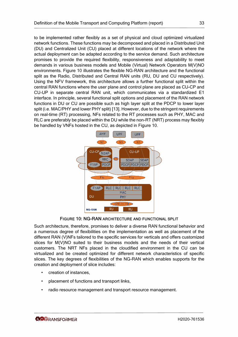
environments. Figure 10 illustrates the flexible NG-RAN architecture and the functional
split as the Radio, Distributed and Central RAN units (RU, DU and CU respectively).
Using the NFV framework, this architecture allows a further functional split within the
central RAN functions where the user plane and control plane are placed as CU-CP and
CU-UP in separate central RAN unit, which communicates via a standardized E1
interface. In principle, several functional split options and placement of the RAN network
functions in DU or CU are possible such as high layer split at the PDCP to lower layer
split (i.e. MAC/PHY and lower PHY split) [13]. However, due to the stringent requirements
on real-time (RT) processing, NFs related to the RT processes such as PHY, MAC and
RLC are preferably be placed within the DU while the non-RT (NRT) process may flexibly
be handled by VNFs hosted in the CU, as depicted in Figure 10.
FIGURE 10: NG-RAN ARCHITECTURE AND FUNCTIONAL SPLIT
Such architecture, therefore, promises to deliver a diverse RAN functional behavior and
a numerous degree of flexibilities on the implementation as well as placement of the
different RAN (V)NFs tailored to the specific services for verticals and offers customized
slices for M(V)NO suited to their business models and the needs of their vertical
customers. The NRT NFs placed in the cloudified environment in the CU can be
virtualized and be created optimized for different network characteristics of specific
slices. The key degrees of flexibilities of the NG-RAN which enables supports for the
creation and deployment of slice includes:
• creation of instances,
• placement of functions and transport links,
• radio resource management and transport resource management.

Definition of the Mobile Transport and Computing Platform (report) 34
H2020-761536
5.3.2.2 RAN Slicing Overview
The Radio network part of the end to end network slice is composed of the radio network
functions associated to this RAN-NSSI. It is responsible for applying the required network
functionality and characterization of the operation of the different logical networks on the
air interface. Depending on the business operation model, a vertical can have a
customized list of requirements to be fulfilled by their network slice in their SLA. The SLA
typically includes various kinds of requirements related to performance, service
coverage, availability, security, reliability. In addition to the QoS demand of each service,
the RAN slice is responsible for enforcing those slice specific SLAs. Unlike to the CN
where slice dedicated instances can be flexibly created using VNFs based on the
virtualized CN infrastructure, there is a limited flexibility and configuration options in the
RAN slice because most of the RAN functions are implemented as a hardware
appliances and RAN resources are expensive and scarce.
5.3.2.2.1 Slice Realization and deployment options in the RAN
A network slice is realized by instantiating associated NFs to deliver the desired e2e
characteristics of the logical network. These NFs are realized on different types of the
network infrastructure element such as dedicated hardware where these NFs are
typically to be shared with less flexibility or on NFV infrastructure where slice customized
VNFs can be flexibly implemented. NG-RAN slice components (RAN-NSSI) and slice
specific NFs implementation can be comprised of both PNFs and VNFs. Moreover,
depending on the deployment strategy and operational model of the M(V)NO, an e2e
NSI can be realized based on RAN-NSSI composed of either slice dedicated or
common/shared RAN-NFs.
For example, in the typical higher layer RAN split deployment option, the lower layers of
RAN functions such as PHY and MAC are implemented in the DU-RAN as a PNF. Some
functionalities of it can either be implemented as slice-specific with dedicated resource
per slice or as a common DU-RAN NFs using a shared resource. However, the fact that
the NFs are implemented as PNF with less flexibility and the limited resources available
in the DU makes the realization of a slice-specific NFs with slice dedicated resource
practically challenging. Moreover, such paradigm may also impose an additional
constraint to the number of slices that can be supported by the RAN. On the other hand,
following the operator’s deployment strategy, the higher layer RAN functions can flexibly
be realized as:
• Common/Shared NFs
o CU-CP/UP common/shared for all slices with partitioned VNF
• Slice dedicated (V)NFs
o CU-CP/UP VNF with dedicated internal resources: e.g. URLLC-slice

Definition of the Mobile Transport and Computing Platform (report) 35
H2020-761536
FIGURE 11: NSI IMPLEMENTATION WITH DEDICATED AND SHARED (V)NFS
One of the characteristics of the e2e slice deployment is the degree of isolation that is
desired to be achieved between slices. One NSI may be fully or partly, logically and/or
physically, isolated from another NSI. In principle, an NSI instantiation may involve either
a newly instantiated NSSI or reusing already created NSSIs across the RAN and CN.
These (V)NFs of the NSSIs can be exclusively used by one slice or shared with another
slice leading to a completely or partly isolated slice deployment, respectively. Slice
isolation over the RAN slice subnet can be achieved to a different degree of flexibility on
the DU and CU. Moreover, slice isolation on the DU where the RAN NFs are mainly
implemented on a shared hardware can be realized via configuration derived from the
SLA to guarantee the desired degree of slice isolation. Such operation can be highly
facilitated and the number of slices to be simultaneously supported can be maximized
via a highly dynamic and automated slice configuration/reconfiguration mechanism.
However, such mechanism might not be practically optimized for some sensitive critical
service supporting slices (e.g. URLLC). For such type of use cases, a dedicated and
isolated slice can be deployed using a static configuration as well as with a dedicated
spectrum or exclusively reserved radio resource on the air interface, Figure 11.
5.3.2.2.2 Network slice deployment and capacity dimensioning
Slices in a 5G mobile network cannot be deployed freely. Slices and their services are
available only within a Registration Area (RA) where the RA consists of one or more
Tracking Area (TA). A TA consists of cells of one or several gNBs. Each TA is identified
by a TA identifier (TAI). As RA information is used only within the CN, defining the
network slice coverage area is done using the TAIs. The size of a TA, small/large, may
have implications mainly on the operation of non-stationary UEs as TA information is
related to UE mobility. For example, UE-Idle mode, the location of a UE is known on
tracking area granularity. Thus, the smaller tracking areas, the more often UEs have to
perform tracking area updates. The association of the supported network slice(s) to the
valid TAI and the information about the mapping of the TAI to the geographical area is
provided to the UEs by the serving cell via broadcasted System Information Blocks (SIB).
Depending on the slice type and the operator business models, some of the slice
coverage may span from a nationwide to a very localized coverage such as in the private
industrial environment. Figure 12 depicts, the slice coverage and TA mapping for mix of
slice deployment situations.

Definition of the Mobile Transport and Computing Platform (report) 36
H2020-761536
FIGURE 12: SLICE COVERAGE AND TRACKING AREA MAPPING
A gNB can support one or more layers of TAs each supports a list of valid slices. For
example, in Figure 12, TAI-#3 could be an area where a slice for a specific localized
industry zone is deployed with a dedicated resource and customized RAN configuration
supporting only slice S-NSSAI-#5 laid over TAI-#1. Whereas TAI-#1 with 3 other slices
listed, on the other hand spans a wider coverage region. The list of slices to be supported
within a TA managed by higher layer management functions and orchestrators. A specific
slice can be added/deleted by the operator or based on a vertical customer need to the
TA list at any time. However, there can be some practical situations such as slice
corresponding to certain S-NSSAI(s) might be temporarily/permanently unsupported in
some cells due to several factors such as RAN incapability, unavailability of the shared
or dedicated (virtual) resources, etc. Such issues make network slice deployment,
service provisioning and ensuring availability of the service anywhere/time challenging.
5.3.2.2.3 Slicing in the context of RAN protocol layers
A 5G UE running diverse applications can simultaneously be connected to several slices
for the respective services. The valid list of the slices a UE can access is indicated by the
UE with NSSAI which consists of a list of one or more S-NSSAI that uniquely identifies a
single slice in one PLMN. Upon registration process and completion of the connection
setup, a PDU session is established for the specific service on a specific slice. Each 5G
QoS flows, which refers to one or group of more IP flows with the same QoS treatment
requirement, can be associated to a PDU session of the slice delivering the service. The
5G-RAN applies the radio resource management (RRM) policy and SLA of supported
slices for the QoS differentiation across and within slice and ensure that the promised
service quality is guaranteed. The 5G QoS framework, the UE subscribed slice list, the
association of the IP flows within a slice and bearer mapping are briefly summarized and
shown across the RAN protocol layers in Figure 13,[14].

Definition of the Mobile Transport and Computing Platform (report) 37
H2020-761536
FIGURE 13: 5Q QOS FRAMEWORK AND QOS FLOW MAPPING WITHIN SLICE
In general, the 5G-RAN may serve a single UE with one or more NSIs simultaneously
where each UE application/service is associated to its slice with the S-NSSAI. The S-
NSSAI is associated to one or more NSI depending on the operator’s deployment
strategy or need. This means S-NSSAI to NSI mapping can optionally be one-to-one or
one-to-many or many-to-one in the same or different TAs [15]. In the case of a fully
shared NSI deployment, several S-NSSAIs are mapped to a single NSI whereas in one-
to-many mapping, multiple NSIs are associated to a single S-NSSAI. Such one-to-many
mapping NSI deployment option may be carried out for various reason such as
redundancy to ensure service availability, ease of NSI-specific service upgrade or for
seamless execution of slice administration/subscription change within a TA. However,
the network at any one time serves the UE with only one of the NSIs associated to the
S-NSSAI and each PDU sessions of a UE belongs to one and only one specific NSI per
PLMN. The network may implement an automated mechanism for slice selection change
and NSI mapping so that UEs can be dynamically steered to the right NSIs. The S-NSSAI
and NSI mapping is illustrated with Figure 14 where NSIs consisting of the corresponding
NFs of the RAN/CN-NSSIs and their interconnection is shown. This separation into
different RAN-NSSIs corresponds to the provisioning of several end-to-end slices as
described in D1.1, Section 1.2 [6]. The S-NSSAI to be used for a specific slice can be
requested by the vertical when instantiating a vertical service or it can be decided by the
5G-TRANSFORMER system. This is similar to deciding on the IP address to address a
service in a datacenter.

Definition of the Mobile Transport and Computing Platform (report) 38
H2020-761536
FIGURE 14: S-NSSAI TO NSI MAPPING
5.3.2.2.4 Slice Aware Radio Resource Management and Impact on Scheduler
The 5G-RAN is the key network element that enables provisioning of the various
applications/services over the air interface network simultaneously to the different slices’
end users. Depending on the slice deployment options employed such as degree of slice
isolation, resource sharing model, SLA and QoS demand of slice services, the RAN
implementation should be able to address these requirements laid by the M(V)NO and
service/slice tenant in an optimized and efficient manner. In this regard, the scheduler is
responsible for ensuring the fulfilment of the QoS and enforcing the SLA as it is the one
who takes care of the radio resource assignment each UE. In this regard, the radio
resource management and scheduler functions are crucial and play key role in ensuring
the delivery of the desired system performance. Besides to the strict service QoS
requirements, tenants might be interested to choose and pay for different options of
resources usage or share scheme on the air interface and how it is granted to their slice
and how slice-specific shares are handled such as exclusive or dynamic sharing manner,
how much of the slice services are prioritized to be considered in the SLA. In general,
the M(V)NO may have several possible resource sharing schemes as part of their
business model
• Shared resource: where no slice specific shares are granted, and no slice priority
is enforced such that a slice is served on first come first served basis.
• Dedicated resource: portion of system resource is dedicated and granted to a
slice. Unless conditioned policy is applied, no other slice can use this dedicated
slice’s share even if it is unused [16].
• Exclusive allocation or dedicated spectrum: the total resource pool of spectrum
is exclusively reserved for a specific slice.
These criteria, if included, within the SLA shall be supported for the slice deployment and
be addressed by the RAN. Hence, this requires defining a slice aware RRM policy and
designing a scheduler that is responsible to fulfil the promised QoS as well as slice
specific-SLAs. However, a mix of different radio resource sharing models employed for
specific-slices might not be efficiently supported simultaneously with one scheduler. On
one hand, different slices may have different frame structure design on the air interface
and implement various scheduling time such as standard-Transmission Time Interval
(TTI), short-TTI, mini-slot which may require a dedicated scheduler function design.
However, an architecture that supports a slice-specific scheduler makes implementation

Definition of the Mobile Transport and Computing Platform (report) 39
H2020-761536
more complex and challenging as the real time processing as well as computing
hardware resources on the RAN are scarce and have limited flexibility and scalability.
5.3.2.3 Practical Aspects of RAN Slicing
With RAN-slicing, the NG-RAN shall be able to flexibly offer different functional
behaviors, support various KPIs and enable to construct flexible SLAs to meet the
demands of specific tenants and slice-specific services. Some of the capabilities include
flexible creation and placement of RAN function instances optimized for a specific slice.
The practical implementation of the gNB’s PNF and VNFs as well as the degree of the
achievable flexibility are limiting factors. The practical limitation on the slice deployment
and slice-based 5G service provisioning for an M(V)NO lies mainly on the RAN subnet
of the end to end slice. This is due to the fact that delivering a different and diverse slices’
services simultaneously on a single physical infrastructure in the most efficient way while
ensuring the promised SLAs for every single business slice is challenging. Furthermore,
the level of isolation that can be practically achieved on the radio air-interface is limited
thereby constraining the ability to independently configure, optimize the RAN parameters
separately per tenant/slice. As the network elements in the RAN are cost optimized
mass-volume products, the efficient usage of the provided resources is crucial.
5.3.2.3.1 gNB capacity requirements regarding Slicing
The RAN capacity dimensioning aspect in terms of slice support is highly dependent on
the employed slice deployment paradigm such as whether the slice is either
statically/semi-statically configured or dynamically deployed. In the static slice
deployment paradigm, each slice-NSI configuration is created and maintained based on
a strict agreement between the vertical/tenant and the M(V)NO and may be due to a
stringent service requirement and/or business model of the tenant. However, such
approach could lead to a limited number of slice support per gNB due to the slice
dedicated resource reservation while resulting in a huge CAPEX and OPEX as well. On
the other hand, a great deal of system automation can enable to apply a more efficient
and dynamic slice deployment where slice specific requirements can be created on a
self-service portal with a list of requirements (which can be handled by the vertical slicer)
and the slice may be created and managed in self-organized manner for the specific
situation, location and time scale. In such dynamic slice deployment, an operator must
use own automation to fulfil the listed service requirement without exclusively dedicating
resources per slice while maintaining the desired operational isolation. Such approach
can effectively control slice life time more dynamically enabling multiplexing of several
slices’ deployment per RAN with in a localized TA as well.
The NG-RAN capacity and the number of slices that can be supported, in general,
depends on the type and capacity demand of the slices within that TA as well as the end
to end capacity of the RAN infrastructure such as computation and transport. Moreover,
the scheme of RAN slice subnet instantiation either via a dedicated or shared network
function is another factor that essentially determines the gNB capacity dimensioning. For
example, the number of slices that can be supported on a single gNb could be related to
the granularity of splitting up resources, for instance a 10Gbps transport interface can be
split in a rather fine granular manner and could be used by 1000 NSIs with non-GBR
traffic, on average providing 10Mbps per NSIs. On the other hand, let’s assume 8 UEs
can be scheduled per TTI and there are several URLLC NSIs. Then at most 8 NSIs can
be supported, allowing one UE per TTI to be scheduled per NSI. Different resources at a
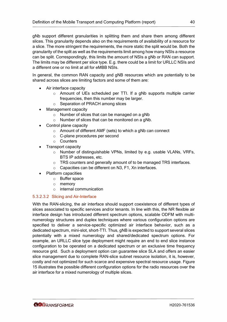
Definition of the Mobile Transport and Computing Platform (report) 40
H2020-761536
gNb support different granularities in splitting them and share them among different
slices. This granularity depends also on the requirements of availability of a resource for
a slice. The more stringent the requirements, the more static the split would be. Both the
granularity of the split as well as the requirements limit among how many NSIs a resource
can be split. Correspondingly, this limits the amount of NSIs a gNb or RAN can support.
The limits may be different per slice type. E.g. there could be a limit for URLLC NSIs and
a different one or no limit at all for eMBB NSIs.
In general, the common RAN capacity and gNB resources which are potentially to be
shared across slices are limiting factors and some of them are:
• Air interface capacity
o Amount of UEs scheduled per TTI. If a gNb supports multiple carrier
frequencies, then this number may be larger.
o Separation of PRACH among slices
• Management capacity
o Number of slices that can be managed on a gNb
o Number of slices that can be monitored on a gNb.
• Control plane capacity
o Amount of different AMF (sets) to which a gNb can connect
o C-plane procedures per second
o Counters
• Transport capacity
o Number of distinguishable VPNs, limited by e.g. usable VLANs, VRFs,
BTS IP addresses, etc.
o TRS counters and generally amount of to be managed TRS interfaces.
o Capacities can be different on N3, F1, Xn interfaces.
• Platform capacities
o Buffer space
o memory
o internal communication
5.3.2.3.2 Slicing and Air-Interface
With the RAN-slicing, the air interface should support coexistence of different types of
slices associated to specific services and/or tenants. In line with this, the NR flexible air
interface design has introduced different spectrum options, scalable ODFM with multi-
numerology structures and duplex techniques where various configuration options are
specified to deliver a service-specific optimized air interface behavior, such as a
dedicated spectrum, mini-slot, short-TTI. Thus, gNB is expected to support several slices
potentially with a mixed numerology and shared/dedicated spectrum options. For
example, an URLLC slice type deployment might require an end to end slice instance
configuration to be operated on a dedicated spectrum or an exclusive time frequency
resource grid. Such a deployment option can guarantee slice SLA and offers an easier
slice management due to complete RAN-slice subnet resource isolation, it is, however,
costly and not optimized for such scarce and expensive spectral resource usage. Figure
15 illustrates the possible different configuration options for the radio resources over the
air interface for a mixed numerology of multiple slices.

Definition of the Mobile Transport and Computing Platform (report) 41
H2020-761536
FIGURE 15: MULTIPLEXED SLICE AND MIXED NUMEROLOGY SUPPORT
In Figure 15 (a), the complete spectral resources are shared by all slices and the burst
arrival of a mini slot/short-TTI slice such as URLLC services can be always prioritized
over the other slices such as eMBB and be scheduled right away. Such scheme is done
in a more dynamic manner and ensures maximized utilization of radio resource while
supporting the slice-specific numerology and scheduling time. Where as in Figure 15(b),
the slice specific resource can be exclusively reserved and the respective frame
structure, numerology configuration types are applied. In this case, each slice is
exclusively reserving its own pool of radio resources guaranteeing resource availability
all the time but may be unused in the absence of slice traffic. Moreover, slice specific
radio resource reservation may require a dedicated RRM entity and logical scheduler
implementation.
5.3.2.3.3 Options for slice aware Radio Resource Scheduling
The requirement to support multiple slices over a single NG-RAN is demanding a
technical solution on how to apply the best radio resource management (RRM) and policy
to fulfil the SLA for each slice while delivering enhanced system efficiency. NG-RAN radio
resource management can be better achieved through RRM slice conditioned policies
and an optimized slice-aware radio scheduler design. In order to optimally manage the
over-all system resource and radio resource usage within a slice and across slices, the
RRM may host a common resource management entity where all the rules and
translations of SLAs of different tenants can be carried out. Such slice specific translation
and supervisions can be done at higher layers of the RAN protocol which can be placed
on the virtualized central RAN units. The scheduler architecture and implemented
algorithm should be aware of a slice and the rules for assigning, reserving and
partitioning of the radio resources of the system as well as the share per slice. Hence, a
more flexible and adaptive resource management and scheduler design is crucial to
provision slice customized RAN-feature while delivering an optimized operational
efficiency.
The architecture and implementation of the slice aware radio resource scheduler design
can be determined by several factors:
• The first factor is the radio resource assignment policy such as resource
reservation and agreed share of slices. Such factors determine, how much
resources are promised and how are those provisioned with either exclusive
share per slice or a flexible slice share letting a more adaptive resource usage
within an inter-slice share.
• The second factor is the desired algorithm implementation to apply the different
metrics and prioritization rules with respect to different slice and their traffic. This
can be attributed to the slice service type, the requested nature of the e2e slice
deployment and the isolation level desired over the RAN slice subnet. For
example, different and customized scheduler algorithms can be implemented for
different slices. Such implementation option may seem to better guarantee

Definition of the Mobile Transport and Computing Platform (report) 42
H2020-761536
service/slice specific metrics however, it is practically challenging from the
system processing limitation.
• The third factor can be driven by the architecture where different scheduler can
be implemented and placed with in the CU or DU depending on the service/slice
type and related requirements on latency: e.g. for eMBB and URLLC type slices.
Independent of how it is implemented, the scheduler should be able to support a more
adaptive and flexible radio resource assignment fulfilling requested SLA and satisfying
the tenant business model while efficiently utilizing the radio and system resource.
Moreover, high level of coordination needs to be supported to coordinate several
scheduling instances across different slices, monitoring slice policies to adaptively react
by monitoring the slice traffic behavior as well.
5.3.2.3.4 Impact of Slicing on Transport
Slicing is impacting a lot as well on the transport networks connecting the virtual or
physical RAN network functions. E2e transport is accomplished using multiple layers and
several segments.
Transport in a mobile network consists of two main layers. The e2e transport layer that
connects the end-user applications running on the UEs to application servers (APs),
clients and peers represents an own IP network of itself that runs on top of the network
elements of the mobile network, which are interconnected within another IP network on
a second layer, which is independent from the first e2e layer.
The e2e IP flows of the first layer are virtually tunnelled through the mobile transport
network forming the second layer.
Segments of the lower layer transport may comprise the low latency fronthaul (like
“eCPRI” over Ethernet or “CPRI” over Fiber), the high latency fronthaul (for interfaces
like “F1” or “W1” used in 3GPP compliant cloudified deployments with central unit (CU)
and distributed unit (DU)), mobile backhaul (for interfaces like “NG2”, “NG3”, “S1” and
“X2”), the IP core network and the datacenter transport networks.
The three first segments are falling traditionally into the RAN transport domain, while the
latter two are traditionally considered as Radio Core transport domain. In 5G networks
however, this split will blur. “Edge Datacenters” for instance will be located much closer
to the applications running on the UEs to allow a short latency for the communication.
The same will hold true for “Mobile Edge Computing” (MEC), where servers are
collocated to BTS sites, allowing fastest response times via local breakouts or similar.
5.3.2.3.4.1 Aspects of slicing on e2e transport layer
Slices form independent networks. In most simple case a UE may connect to just one
slice (e.g. an IoT device to the IoT slice). Slices are forming as well independent
addressing domains. This means that another device, connected to another slice, may
use the same IP address value as the first device that, however, is placed in another
slice.
3GPP specifies that one UE will be able to connect to up to eight slices. A UE needs in
this case to be able to provide at least eight independent IP interfaces that can connect
to up to eight independently managed IP addressing domains. Each of the eight
interfaces will be served via its own set of QoS flows and bearers in the air interface.

Definition of the Mobile Transport and Computing Platform (report) 43
H2020-761536
This has implications as well to the operating systems used for the UEs. The UEs and
their operating systems need to support isolation for the slices, the applications running
within those and the IP connection to the outside world, if needed. Today’s operating
systems need thus to be extended.
Support for SW Containers, Virtual Machines or isolation done by other methods must
be introduced in Android, IOS or other mobile OS to fully use the benefits of the slicing
concept in a single device.
5.3.2.3.4.2 Aspects of slicing in RAN transport networks
Transport is organized as a set of layers. The most prominent Transport Stack is the OSI
seven-layer stack. The most used one is the Ethernet/IP stack. However, in RAN
transport networks also other stacks (e.g. optics/WDM, OTN) are implemented.
- Low latency Fronthaul Network Segment
Low latency fronthaul networks connect the baseband units of an DU doing the radio
signal processing with the radio units (RU) emitting the actual radio waves. Traditional
radio units have the building blocks for sending and receiving the radio signals but have
only rudimentary network functions.
The widely used CPRI is a TDM based interface, not used outside radio networks.
Combined with the stringent latency requirements there is barely equipment available for
networking on CPRI layer. Most often CPRI links are built as point-to-point connections
using dedicated fibres or as WDM network with dedicated wavelengths per CPRI
connection.
CPRI links carry antenna signals that comprise a time-domain series of combined IQ-
data of all UEs of a particular cell. The minimum granularity that can be allocated to one
slice is thus “cell” as well. While for some vertical services, like public safety networks,
this may be sufficient, for the bulk of the other projected vertical services the low latency
CPRI Fronthaul network does not allow isolation of individual slices.
With the advent of Ethernet based eCPRI the general situation improves in terms of
packet-based networking. Ethernet Switches are widely available and widely deployed.
However, the situation does not change regarding the support of slicing. With the
currently standardized PHY splits, comprising a series of frequency-domain IQ symbols,
it is still not possible to generate independent flows to a dedicated UE in a cell or to
particular slice terminations within one UE. Again, the smallest granularity that can be
allocated to a slice is “cell”. - High Latency Fronthaul Network Segment and Mobile
Backhaul Segment
The high latency Fronthaul Network segment (sometimes called “midhaul network”),
spans between the DU and the CU of an gNB or eNB. Both, CU and DU may host
virtualized functions of the BTS, connected via standardized interfaces, like F1 in case
of NR or the coming W1 in case of LTE.
The traditional Mobile Backhaul Segment connects the backhaul interfaces of the gNB-
CU, like N2, N3, Xn and X2 with the core functions or adjacent gNBs and eNBs. Backhaul
interfaces of LTE eNBs comprise S1 and X2.
5G CU and DU as described above are slice aware and can setup e.g. the F1 interface
in a way that allows the isolation of slices within the transport segment. The management
granularity in the high latency Fronthaul network is on bearer level. One bearer, with in

Definition of the Mobile Transport and Computing Platform (report) 44
H2020-761536
case of NR all contained QoS flows, belongs to one slice. Thus, a mapping is possible
and slice isolation can be done.
While bearers are a supported concept in eNB backhaul interfaces S1 and X2, they do
not exist in the N2 and N3 backhaul interfaces of an NR gNB. They are replaced by the
above mentioned QoS flows. As QoS flows are finer granular than bearers and can be
as well mapped to slices.
Isolation among the slices may happen on several layers of the transport stack. At the
physical interface of the DU or the CU, VLANs may be used for Ethernet based networks.
However, as most mobile transport networks are IP based, virtual IP interfaces belonging
to one slice can be implemented by a virtual routing function (VRF). This isolates the IP
address spaces among each other and allows independent allocation of IP addresses
within each space.
For the actual transport network between CU and DU and between CU and core quite
often provider-based VPNs are applied. Many solutions for L2 and L3 networks exist,
more traditional ones including MPLS, or new emerging ones, like Openflow-
controlled[17].
- Datacenter Transport
The transport network connecting different servers within a DC differs significantly from
the transport networks as described for low latency fronthaul, high latency fronthaul and
mobile backhaul networks.
DCs are designed to cope with an enormous number of tenants and applications that are
deployed in a uniform, consistent computing environment. Deployment speeds of
software are measured rather in seconds than days. This requires a high degree of
automation. In fact, many of the concepts of software defined networking that now are
proposed for the mobile transport have been originally developed for DCs.
Common building elements of DCs are servers, racks and pods. Several servers are
mounted in a rack and some racks form a pod. Special pods exist for connecting the DCs
with the outside world via edge routers.
One commonly used topology for DC networks today is the so-called multi-tier Clos
network. A Clos network provides not only good connectivity of the servers towards the
outside world (north-south traffic), but as well for the traffic flowing between the servers
within the DC (east-west traffic). The first tier of switches, which are connected directly
to the servers are called top-of-rack (ToR) switches after their usual location, i.e. the top
of the server rack. The switches in the next tier are called leave switches. They connect
the ToR switches within a pod. Finally, the pods are connected via the next tier of
switches called spines switches.
Multitenancy and traffic isolation are inbuild features of DC. Thus, those networks are
well prepared for the isolation of traffic belonging to different slices. One way to do this
is using Virtual eXtensible Local Area Networks (VXLANs) and IP-in-IP tunnels together
with a routing protocol (BGP, OSPF or IS-IS) in the Clos Network.
5.3.3 Monitoring
The 5GT-MTP monitoring service is in charge of collecting monitoring parameters related
to the managed physical infrastructure in support of assurance of the requested QoS and
the optimization of the infrastructure usage in general. In particular, the monitoring at the

Definition of the Mobile Transport and Computing Platform (report) 45
H2020-761536
5GT-MTP level addresses the metrics related to the utilization and the performance of
the physical and the virtual infrastructure, in terms of computing and network resources.
However, it does not focus on the consumption of virtual resources associated to specific
virtual functions or network services, since such parameters are handled at the 5GT-SO
monitoring level.
The 5GT-MTP monitoring service relies on a monitoring platform that follows the same
architecture of the 5G-TRANSFORMER monitoring platform defined in D4.3 [11]. In this
case, the monitoring data is extracted from the infrastructure through different kinds of
monitoring agents, depending on the type of target measurements. In particular, for
monitoring data related to physical resources, the agents operate on the network or in
the physical servers, while for monitoring the virtual resources the agents work at the
VIM or WIM level. For what concerns the monitoring of networking resources, the agents
can be embedded in the SDN controller acting as WIM. This approach is particularly
suitable to collect data about the traffic exchanged on specific links, or statistics about
the packets received, transmitted or dropped in particular ports. Moreover, additional
agents may be deployed in dedicated monitoring elements that interact with network
probes or active monitoring tools (e.g. embedding traffic generators or traffic shapers).
This approach may be adopted to perform measurements related to statistical metrics of
bandwidth or delay in a given network segment. Regarding computing resources, the
agents embedded in the servers are able to collect data related to power consumption,
load of traffic on the server’s network interfaces, CPU, memory or disk utilization.
Operating at the VIM level (e.g. through an agent collecting data from OpenStack), it is
possible to collect further data associated to single virtual resources, like the resource
utilization for specific Virtual Machines.
The original monitoring data collected through the different agents is stored in the
monitoring platform and made available for queries and reports. Alert notifications are
also supported through a subscription-based approach (see D4.3 [11] for further details
about alerts generation in 5G-TRANSFORMER monitoring platform). The monitoring
data collected at the 5GT-MTP monitoring platform is mostly consumed by the 5GT-MTP
itself, e.g., to detect failures at the infrastructure level or to feed its internal resource
allocation algorithms. A subset of these monitoring parameters may also be exposed to
the 5GT-SO monitoring platform, e.g. through the mediation of additional agents
deployed on the 5GT-SO side. However, it should be noted that the 5GT-MTP, acting as
a “management entity” of the physical infrastructure, is allowed to retrieve monitoring
data related to both physical and virtual resources. On the other hand, the level of
information exposed to the 5GT-SO is limited to virtual resources only (e.g. the
consumption of CPU for a given VM or the traffic load in a virtual network).
The workflow to activate monitoring for a given set of physical or virtual resources at the
5GT-MTP level follows the same procedures defined for the configuration of monitoring
jobs and monitoring alerts at the 5GT-SO level (see D4.3 [11] for further details). In
summary, this workflow requires the initial creation of performance monitoring jobs to
collect elementary measurements through “exporters” (i.e. the monitoring agents)
retrieving data from servers, network monitoring tools, VIMs and/or WIMs. Then one or
more dashboards can be created to visualize graphs with performance metrics via web
browser. This reporting can be accessed by the infrastructure provider or by the
consumers of the 5GT-MTP interfaces. Finally, subscriptions can be created based on
arbitrary thresholds on the collected data, allowing the 5GT-MTP to monitor the
infrastructure and react whenever a failure or a performance degradation is detected.

Definition of the Mobile Transport and Computing Platform (report) 46
H2020-761536
5.3.4 Optimization algorithms
The optimization algorithm/s at the 5GT-MTP aim at providing a more granular and/or
expanding the output of the executed 5GT-SO PA regarding the heterogeneous
resources to be selected and allocated for a specific network service. It is worth outlining
the heterogeneity aspect that those algorithms and mechanisms must encompass with
respect to the resources entailing: cloud, transport and RAN. Bearing this in mind, it
becomes notably complex devising a single algorithm which is able to optimize the
allocation of the resources on top of the resource heterogeneity. For this reason, a
plausible solution relies on segmenting the optimization on technological / resource
basis. In other words, a specific algorithm is devised to optimize the selection and
allocation of the resources regarding the intrinsic features of those resources. Thus, in
the following it is addressed different algorithms specifically tailored to particular
resources / network segments, namely, transport WAN, intra-NFVI-Pop cloud and RAN.
5.3.4.1 Placement algorithm (PA)
5.3.4.1.1 Logical Link Placement Algorithm (LL-PA)
The output of the 5GT-SO’s PA algorithm is typically formed by a selected set of NFVI-
PoPs where the corresponding VNFs will be instantiated as well as a set of Logical Links
(LLs) that would enable the inter-NFVI-PoP connectivity satisfying the network service
requirements. This output is then sent to the 5GT-MTP to be processed and used for
conducting the operations and actions (e.g., cloud and network resource allocation) to
come up with the deployment of a particular network service. In this set of operations and
actions, due to the different abstraction mechanisms adopted in the 5GT architecture, it
might be needed to trigger a new PA computation (but at the 5GT-MTP level), referred
to as Logical Link PA (LL-PA) to accomplish a more accurate selection of the resources.
Herein, we focus on the description of the 5GT-MTP LL-PA where the objective is to
optimize the inter-NFVI-PoP network resources, i.e. WAN domains and inter-WAN links.
The targeted optimization of 5GT-MTP’s LL-PA aims at attaining the most efficient use
of the network resources in terms of link bandwidth (e.g., balancing the use of the
available bandwidth), network elements (i.e., switch) ports, etc, whilst satisfying the
requirements associated to every LL. In this regard one of the main assumptions is that
the pool of LLs at the 5GT-SO level for its PA may not be necessarily bound to a pre-
defined and static inter-NFVI-PoP path. By doing so, some sort of flexibility is provided
to the 5GT-MTP’s LL-PA to compute and select those network resources that eventually
allow accomplishing a more efficient use of the inter-NFVI-PoP resources.
Proposed LL-PA algorithm
The input information used by the proposed inter-NFVI-PoP 5GT-MTP LL-PA algorithm
is:
- View of the network resources (i.e., nodes, links and related QoS attributes such
as available bandwidth, delay/latency and cost/metric) of both WAN domains as
well as inter-WAN links. Observe that the internal vision of each WAN domain is
subject to the abstraction provided by the corresponding WIM plugin handling that
domain.
- QoS constraints bound to a specific LL. Selected LLs for a network service made
by the 5GT-SO’s PA are assumed to be associated to a set of QoS parameters
(which in turn must satisfy the network service requirements). Consequently, the
QoS constraints that the 5GT-MTP’s LL-PA needs to deal with are related to
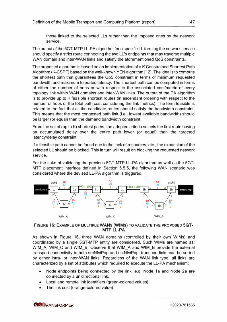
Definition of the Mobile Transport and Computing Platform (report) 47
H2020-761536
those linked to the selected LLs rather than the imposed ones by the network
service.
The output of the 5GT-MTP LL-PA algorithm for a specific LL forming the network service
should specify a strict route connecting the two LL’s endpoints that may traverse multiple
WAN domain and inter-WAN links and satisfy the aforementioned QoS constraints.
The proposed algorithm is based on an implementation of a K Constrained Shortest Path
Algorithm (K-CSPF) based on the well-known YEN algorithm [12]. The idea is to compute
the shortest path that guarantees the QoS constraint in terms of minimum requested
bandwidth and maximum tolerated latency. The shortest path can be computed in terms
of either the number of hops or with respect to the associated cost/metric of every
topology link within WAN domains and inter-WAN links. The output of the PA algorithm
is to provide up to K feasible shortest routes (in ascendant ordering with respect to the
number of hops or the total path cost considering the link metrics). The term feasible is
related to the fact that all the candidate routes should satisfy the bandwidth constraint.
This means that the most congested path link (i.e., lowest available bandwidth) should
be larger (or equal) than the demand bandwidth constraint.
From the set of (up to K) shortest paths, the adopted criteria selects the first route having
an accumulated delay over the entire path lower (or equal) than the targeted
latency/delay constraint.
If a feasible path cannot be found due to the lack of resources, etc., the expansion of the
selected LL should be blocked. This in turn will result on blocking the requested network
service.
For the sake of validating the previous 5GT-MTP LL-PA algorithm as well as the 5GT-
MTP placement interface defined in Section 5.5.5, the following WAN scenario was
considered where the devised LL-PA algorithm is triggered.
FIGURE 16: EXAMPLE OF MULTIPLE WANS (WIMS) TO VALIDATE THE PROPOSED 5GT-MTP LL-PA
As shown in Figure 16, three WAN domains (controlled by their own WIMs) and
coordinated by a single 5GT-MTP entity are considered. Such WIMs are named as:
WIM_A, WIM_C and WIM_B. Observe that WIM_A and WIM_B provide the external
transport connectivity to both srcNfviPop and dstNfviPop. transport links can be sorted
by either intra- or inter-WAN links. Regardless of the WAN link type, all links are
characterized by a set of attributes which required to execute the LL-PA mechanism:
• Node endpoints being connected by the link, e.g. Node 1a and Node 2a are
connected by a unidirectional link.
• Local and remote link identifiers (green-colored values).
• The link cost (orange-colored value).
1a 2a
3a
3c
2c
1c 2b
3b
1b dstNfviPopsrcNfviPop
WIM_A WIM_C WIM_B
srcPE dstPE
1
21
2
2
2
2
2
2
2
2
1
1
1
1
1
1
1
1001 1001 10021002
10 20 1
10 20 1
10 20 1
10 20 1
10 20 1
10 20 1
10 20 1
10 20 1
10 20 1
10 20 1

Definition of the Mobile Transport and Computing Platform (report) 48
H2020-761536
• The available bandwidth (blue-colored values).
• The associated link delay (red-colored value).
The above intra- and inter-WAN link information constitutes indeed the WAN topology
passed to the LL-PA (via the API described in Section 5.5.5). As input information to the
LL-PA is also delivered the two Provider Edge (PE) nodes associated to the LL required
to be expanded by the algorithm. In the example shown in Figure 16, the targeted LL to
be expanded connects both srcNfviPop and dstNfviPop. In the request LL-PA
computation is also indicated the amount of available bandwidth to be allocated through
the computed WAN path supporting the LL as well as the maximum end-to-end latency
that the output WAN path must not exceed. Using the defined REST API, the request
sent by the 5GT-MTP to the LL-PA with the above information and parameters is
reflected in the following figure. In the figure, it is shown the response of the LL-PA
mechanism which carries the successful computed WAN being formatted as detailed in
Section 7.5.5. For the considered example the computed path is though the route formed
by the nodes: 1a → 2a → 3c → 1c → 2b → 1b. The exchanged request/response
messages along with the computed path takes around 25 ms.
FIGURE 17: REST LL-PA API EXECUTING THE LL-PA
5.3.4.1.2 VNF Placement algorithm (VNF-PA)
In this Section we present an algorithm for VNF placement within a NFVI-PoP, which
minimizes the power consumption of the NFVI-PoPs, managed by the 5G-
TRANSFORMER platform. Our optimization is of utmost importance, since it helps
meeting two project KPIs, i.e., energy efficiency and, indirectly, OPEX reduction. In the
following, it is assumed that the 5GT-MTP receives the associations among VNF/NFVI-
PoP from the 5GT-SO. By doing so, the proposed VNF-PA algorithm is able to choose
on which specific machine (e.g., server) of the NFVI-PoP the VNF has to be actually
allocated and run. Therefore, our objective is to obtain a VNF PA algorithm that minimizes
energy consumption at each NFVI-PoP.
Next, we first formalize our problem as a multi-resource Generalized Assignment
Problem, then we present our heuristic algorithm and our simulation results.
Request: 5GT-MTP → LL-PA
Response: LL-PA → 5GT-MTP
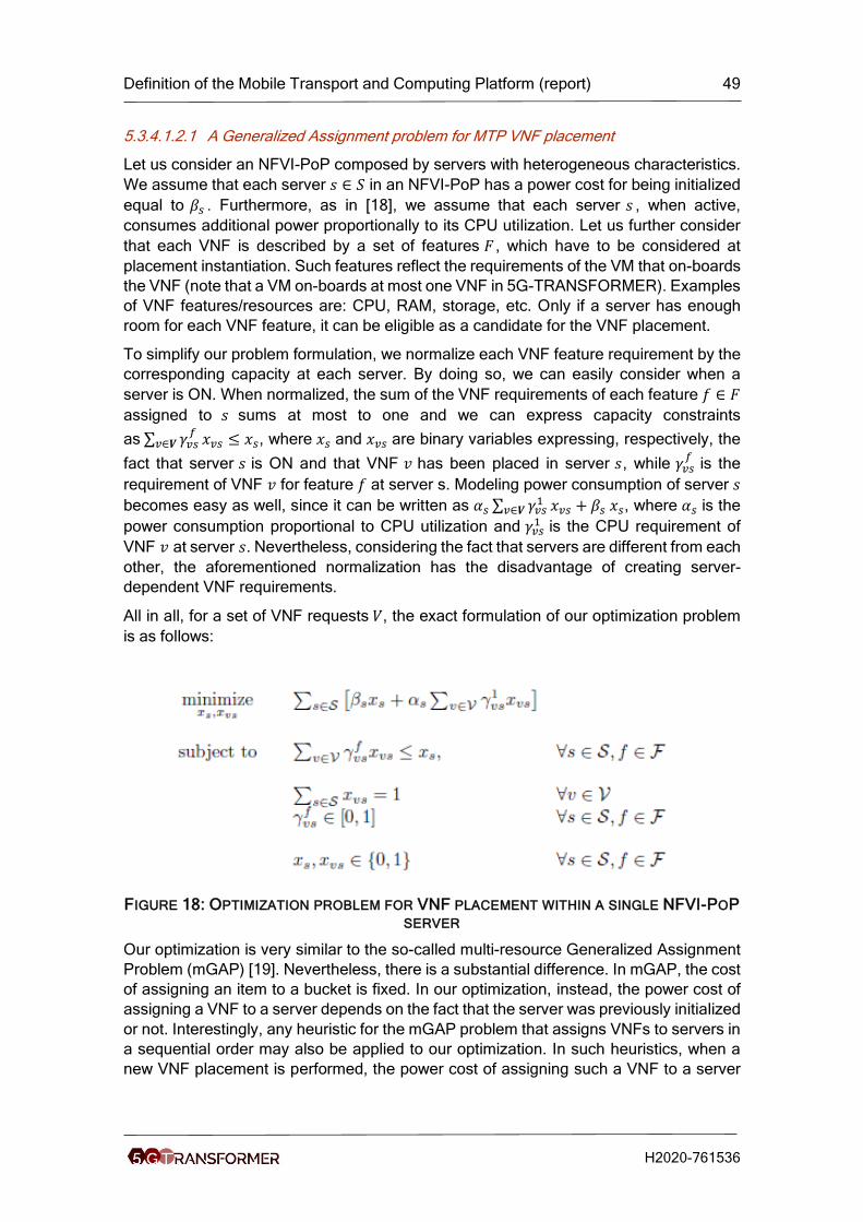
Definition of the Mobile Transport and Computing Platform (report) 49
H2020-761536
5.3.4.1.2.1 A Generalized Assignment problem for MTP VNF placement
Let us consider an NFVI-PoP composed by servers with heterogeneous characteristics.
We assume that each server 𝑠 ∈ 𝑆 in an NFVI-PoP has a power cost for being initialized
equal to 𝛽𝑠 . Furthermore, as in [18], we assume that each server 𝑠 , when active,
consumes additional power proportionally to its CPU utilization. Let us further consider
that each VNF is described by a set of features 𝐹 , which have to be considered at
placement instantiation. Such features reflect the requirements of the VM that on-boards
the VNF (note that a VM on-boards at most one VNF in 5G-TRANSFORMER). Examples
of VNF features/resources are: CPU, RAM, storage, etc. Only if a server has enough
room for each VNF feature, it can be eligible as a candidate for the VNF placement.
To simplify our problem formulation, we normalize each VNF feature requirement by the
corresponding capacity at each server. By doing so, we can easily consider when a
server is ON. When normalized, the sum of the VNF requirements of each feature 𝑓 ∈ 𝐹
assigned to 𝑠 sums at most to one and we can express capacity constraints
as ∑ 𝛾𝑣𝑠𝑓
𝑣∈𝑽 𝑥𝑣𝑠 ≤ 𝑥𝑠, where 𝑥𝑠 and 𝑥𝑣𝑠 are binary variables expressing, respectively, the
fact that server 𝑠 is ON and that VNF 𝑣 has been placed in server 𝑠, while 𝛾𝑣𝑠𝑓
is the
requirement of VNF 𝑣 for feature 𝑓 at server s. Modeling power consumption of server 𝑠
becomes easy as well, since it can be written as 𝛼𝑠 ∑ 𝛾𝑣𝑠1
𝑣∈𝑽 𝑥𝑣𝑠 + 𝛽𝑠 𝑥𝑠, where 𝛼𝑠 is the
power consumption proportional to CPU utilization and 𝛾𝑣𝑠1 is the CPU requirement of
VNF 𝑣 at server 𝑠. Nevertheless, considering the fact that servers are different from each
other, the aforementioned normalization has the disadvantage of creating server-
dependent VNF requirements.
All in all, for a set of VNF requests 𝑉, the exact formulation of our optimization problem
is as follows:
FIGURE 18: OPTIMIZATION PROBLEM FOR VNF PLACEMENT WITHIN A SINGLE NFVI-POP
SERVER
Our optimization is very similar to the so-called multi-resource Generalized Assignment
Problem (mGAP) [19]. Nevertheless, there is a substantial difference. In mGAP, the cost
of assigning an item to a bucket is fixed. In our optimization, instead, the power cost of
assigning a VNF to a server depends on the fact that the server was previously initialized
or not. Interestingly, any heuristic for the mGAP problem that assigns VNFs to servers in
a sequential order may also be applied to our optimization. In such heuristics, when a
new VNF placement is performed, the power cost of assigning such a VNF to a server

Definition of the Mobile Transport and Computing Platform (report) 50
H2020-761536
contains, if needed, the initialization power cost. Table 11 summarizes the variables used
in this section.
TABLE 11: NOTATIONS
Variable Description
V Set of VNFs requests
S Set of Servers
F Set of Features for each request
𝛽𝑠 power cost for initializing 𝑠 ∈ 𝑆
𝛼𝑠 proportional power cost for CPU utilization at 𝑠 ∈ 𝑆
𝛾𝑣𝑠𝑓
requirement of 𝑣 ∈ 𝑉 for feature 𝑓 at server 𝑠
𝑥𝑠 binary variable, ON/OFF server 𝑠
𝑥𝑣𝑠 binary variable, VNF 𝑣 assigned to server 𝑠
5.3.4.1.2.2 The MTP VNF placement algorithm
The mGAP is an optimization problem which has been widely studied, and several
heuristics have been presented. Therefore, we exploit the state-of-the-art solutions,
tailoring them to our specific problem. As mentioned above, the 5GT-MTP receives from
the 5GT-SO the VNF/NFVI-Pop associations. To exploit off-line heuristics, which perform
better than the on-line ones, we assume that the 5GT-MTP does not executes instantly
the decisions of the 5GT-SO. Rather the 5GT-MTP stores them for a time window T.
Upon the time window T expires, the 5GT-MTP places all the VNFs collected and
migrates all the VNFs of non-critical services altogether, exploiting an off-line heuristic
[19]. Herein, we present the pseudo-code of such a heuristic (see below Figure 19) and
its application to our optimization problem.

Definition of the Mobile Transport and Computing Platform (report) 51
H2020-761536
FIGURE 19: HEURISTICS FOR VNF PLACEMENT
In Algorithm 1, we assume that the set of VNFs that needs to be placed/migrated is
represented by 𝑉. First, for each VNF 𝑣 ∈ 𝑉, the set 𝑆𝑣 of servers that can host 𝑣 is
obtained. At this stage, if a VNF 𝑣 cannot be placed to any server, the algorithm returns
unfeasible solution. Such event is possible since the SO, when assigning VNFs to NFVI-
PoPs, has only aggregate knowledge on the NFVI-PoP capacity. For this reason, it is
possible that no actual machine can host a VNF that the SO assigned to a specific NFVI-
PoP. If instead all VNFs have at least a server to be assigned to, then the MTP computes
VNF placements. For the 5GT-MTP, a VNF is critical if the energy efficiency difference
between the first and the second best choice for 𝑣 is the largest in 𝑉. Looping over 𝑉, the
5GT-MTP always assigns the most critical VNF to its best choice up to concluding VNF
placement.
5.3.4.1.2.3 Simulation Results
We now seek to understand how close the performance of the heuristic algorithm
described in Section 5.3.4.1.2.2 is to the optimum. To this end, we consider a reference
scenario including:
• 10 non-homogeneous servers, whose capacity varies between 10 and 20 vCPUs;
• up to non-homogeneous VNFs, whose requirements vary between 0.1 and 2
vCPUs.
Our main metric of interest is the power consumption, computed considering the typical
figure of 85 W per vCPU.
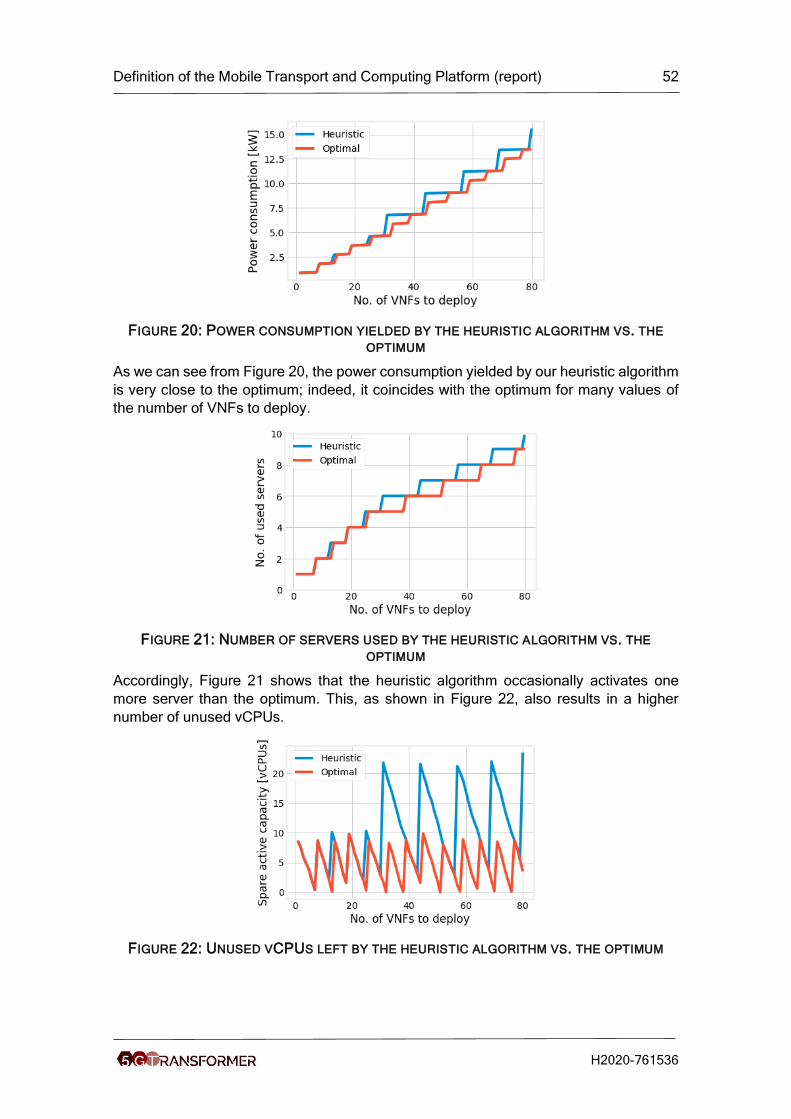
Definition of the Mobile Transport and Computing Platform (report) 52
H2020-761536
FIGURE 20: POWER CONSUMPTION YIELDED BY THE HEURISTIC ALGORITHM VS. THE
OPTIMUM
As we can see from Figure 20, the power consumption yielded by our heuristic algorithm
is very close to the optimum; indeed, it coincides with the optimum for many values of
the number of VNFs to deploy.
FIGURE 21: NUMBER OF SERVERS USED BY THE HEURISTIC ALGORITHM VS. THE
OPTIMUM
Accordingly, Figure 21 shows that the heuristic algorithm occasionally activates one
more server than the optimum. This, as shown in Figure 22, also results in a higher
number of unused vCPUs.
FIGURE 22: UNUSED VCPUS LEFT BY THE HEURISTIC ALGORITHM VS. THE OPTIMUM

Definition of the Mobile Transport and Computing Platform (report) 53
H2020-761536
5.3.4.2 RAN Split algorithms
The increasing mobile data traffic and the new demanding services ranging from augmented reality to Industry 4.0 applications challenge the performance of RAN and
induce unprecedented expenditures to mobile operators. 2 It is apparent today that methods such as the densification of base stations (BS) and the over-provisioning of network links, albeit necessary, cannot address this problem in its entirety; and therefore new RAN solutions are required.
Distributed architectures (D-RAN) used in 3G/4G are cost-inefficient for dense networks
due to their expensive radio units, and because they do not facilitate resource pooling.
On the other hand, centralized RAN (C-RAN) architectures that have recently gained
momentum, relocate most BS functions from low-cost Radio Units (RUs) to a central unit
(CU). RUs perform physical-layer tasks and exchange I/Q radio samples with the CUs
through the fronthaul network. This reduces costs and improves performance through
the central control of tasks such as interference management. However, C-RAN’s
stringent latency and bandwidth requirements are hard to meet in most RAN
deployments nowadays, while clean-slate fronthaul designs are very costly.
When such pure distributed (D-RAN) or fully centralized (C-RAN) solutions fall short, a
hybrid RAN design where only some BS functions are centralized might be more suitable.
Indeed, we see today a flurry of activities in this space by standardization bodies such as
the IEEE 1914 WG and 3GPP RAN3. These efforts build upon the recent softwarization
and cloudification of C-RAN through SDN/NFV (Software-Defined Networking/Network
Function Virtualization) tools. This enables operators to determine the centralization level
(functional split) of the so-called virtual RAN (vRAN) functions for each RU and in a way
that accounts for the available network resources and user demand. This fine-grained
network management approach is considered very important for the success of 5G
systems. Nevertheless, designing the vRAN architecture is a novel and particularly
challenging problem: each configuration has different bandwidth and latency
requirements for data transfers across the function locations; involves different amounts
of resources (computing power, link capacities); and induces different costs and
performance benefits.
There are several levels of centralization, but the key splits are those in Figure 23. Split
1 does not have traffic overheads, enables the co-location of tasks of BSs, and enhances
user mobility management. Whenever a CU is available, essentially there is no reason
not to have split 1. Split 2 improves hardware utilization, enables multi-cell coordination
for CoMP and eICIC, but has significant traffic overheads and an order of magnitude
tighter delay bound (for data transfers among function locations). Finally, split 3 (C-RAN)
consumes very high bandwidth (which is load-independent), has extremely low delay
bounds, but maximizes spectrum efficiency and hardware usage. Finally, regarding the
fronthaul, the expensive point-to-point links are expected to be replaced with packet-
based shared links.
2 For example, China Mobile reported for 2014 115.1% increase in mobile traffic, but
10.2% profit reduction (Proc. 1st IEEE 5G Summit’15).

Definition of the Mobile Transport and Computing Platform (report) 54
H2020-761536
FIGURE 23: BANDWIDTH AND LATENCY REQUIREMENTS OF MAIN SPLITS; FUNCTION 𝐟𝟐
REQUIRES 𝐟𝟏, AND PLACEMENT OF 𝐟𝟑, 𝐟𝟎 IS FIXED; 𝛌 IS THE TRAFFIC
Despite the interest of industry and academia, we currently lack a methodology for
designing vRANs. At the core of this intricate problem lies the decisions for selecting the
function splits and the CUs-RUs routing paths which, clearly, should be jointly devised.
Indeed, the optimal function placement for each depends on the capacity and latency of
the RU-CU network path, which can only be known after the paths for the entire RAN are
selected. On the other hand, finding the optimal path requires knowledge of the flow
requirements in terms of volume and latency, which depend on the functional split of
each BS. This coupling makes a traditionally challenging routing problem even harder
due to the multiple split choices per BS.
The vRAN design problem is further compounded by the advent of (multi-access) edge
computing (MEC), a business model where operators lease computing and network
resources to vertical sectors, e.g., e-health industry. MEC services target ultra-low
latency and high-bandwidth applications and therefore are mainly deployed close to
users; and this, in turn, presumes a full-stack D-RAN implementation. Thus, there is an
inherent tension between MEC and vRAN, which aims at the highest possible
centralization of the RAN functions. Given the importance of MEC services (a new
revenue source for operators) it is imperative to jointly design them with vRAN, in order
to ease this tension and ensure that their performance will meet the expectations set in
5G.
5.3.4.2.1 FluidRAN
We propose FluidRAN, a rigorous analytical framework for the optimized design of virtual
RAN (vRAN) networks. We model the BS operation as a chain of functions that
successively process the traffic to/from the users. Some of these functions (e.g., PDCP
in LTE systems) can be implemented in virtual machines (VMs) at the RUs or CUs; while
others (e.g., turbo(de)coding in LTE systems) require specific hardware. The function
implementation induces a computing cost that may vary across RUs and CUs, and
similarly the selected paths affect the data transfer expenses. Our framework yields the
vRAN configuration (splits and paths) that minimizes the aggregate operator
expenditures.
Our contributions can be summarized as follows:
• Optimization Framework. We introduce an analytical framework for the vRAN design by considering the network and computing resources, and the splits’ requirements. Our solution optimizes the placement of vRAN functions jointly with the data routing; and we leverage the Benders’ decomposition method to enable its derivation for large systems.
• Joint vRAN and MEC Design. We analyze and model the inherent tension among vRAN and MEC. Our framework is extended to jointly decide the placement of MEC

Definition of the Mobile Transport and Computing Platform (report) 55
H2020-761536
services and vRAN functions, yielding a configuration that balances performance benefits and associated costs.
• Performance Evaluation Using Real Networks. We analyze 3 backhaul/RAN topologies of different operators, and use market data for costs and 3GPP specs. We show that there is not a one-size-fits-all vRAN configuration and that in practice packetized CPRI-based C-RAN is rarely a feasible solution; on the other hand, FluidRAN, provides significant cost benefits compared to D-RAN.
5.3.4.2.1.1 System Model
Fronthaul Network. We consider a RAN with a set 𝒩 of 𝑁 RUs and 1 CU.3 These are
connected through a packet-based network 𝐺 = (ℐ, ℰ), where ℐ is the superset of routers,
CU (node 0) and the RUs; and ℰ is the set of links connecting these elements. Each link (𝑖, 𝑗) ∈ ℰ has capacity 𝑐𝑖𝑗 (Mb/s) and introduces delay 𝑑𝑖𝑗 (secs). Let 𝑝: =
{(0, 𝑖1), (𝑖1, 𝑖2), … , (𝑖𝐿 , 𝑛): (𝑖, 𝑗) ∈ ℰ} denote a CU-RU 𝑛 path; 𝒫𝑛 is the set of all RU 𝑛 paths
and 𝒫 =∪𝑛=1𝑁 𝒫𝑛 the set of all CU-RUs paths. Each 𝑝 ∈ 𝒫 is described by the aggregate
delay 𝑑𝑝 of its constituent links. There is an average data transfer cost due to consumed
energy, leasing costs, equipment utilization, etc. We denote 𝛾𝑝 the cost for path 𝑝
(monetary units/byte) and define the routing cost vector:
𝛄 = (𝛾1, 𝛾2, … , 𝛾|𝒫|) .
RAN Functions. The RAN operation is modeled as a chain of 4 functions: 𝑓0, 𝑓1, 𝑓2, and
𝑓3 . Function 𝑓0 corresponds to the basic radio tasks (analog processing, etc.) and it is placed at RUs. Assuming LTE, 𝑓3 corresponds and is always placed at the CU (whenever
there is one available). On the other hand, 𝑓2 and 𝑓1 are placed either at RUs or CU, and this decision is devised independently for each RU. The function placement sets the
delay-bandwidth requirements between the CU and each RU, Figure 23. In vRAN 𝑓2
and 𝑓1 can be implemented in virtual machines (VMs). The cost for initiating and using a VM depends on the hardware. CUs are in central facilities and use high-end servers; hence this cost will be lower compared to RUs. We denote with 𝛼𝑛 (monetary units) the
average (offset) cost for instantiating a VM in RU 𝑛 (due to cooling, leasing fees, etc.), with 𝛽𝑛 (monetary units per cycle) the average cost for serving each request; and define
the respective parameters 𝛼0, 𝛽0 for CU. The computing cost vectors are then:
𝛂 = (𝛼0, 𝛼1, 𝛼2, … , 𝛼𝑁), 𝛃 = (𝛽0, 𝛽1, 𝛽2, … , 𝛽𝑁) .
We denote with 𝜌1 and 𝜌2 the (nominal) processing loads (cycles per Mb/s) of 𝑓1 and 𝑓2,
respectively. Moreover, each RU 𝑛 and CU have processing capacity 𝑃𝑛 and 𝑃0 (cycles), shared by the VMs. When the load is below these bounds, a constant (and very small) processing delay is induced.
Demand. Each RU 𝑛 serves the requests of users that are generated by an i.i.d.
process{𝛬𝑛(𝑡)}𝑡=1∞ , with 𝐸[𝛬𝑛(𝑡)] = 𝜆𝑛 (Mb/s) and we denote the vector 𝛌 = (𝜆𝑛: 𝑛 ∈ 𝒩).
The requests at RU 𝑛 create an aggregate flow emanating from the CU routed to RU 𝑛.
Hence, the RAN operation can be modeled as a multi-commodity flow problem where
the flows depend on the placement of RAN functions.
The objective of the operator is to select the vRAN configuration that will satisfy the users’ demand while minimizing the aggregate expenditures. The latter, in such virtualized
3 We consider 1 CU, as in practice the RUs are assigned to CUs before split decisions; and most often there is 1 CU location.

Definition of the Mobile Transport and Computing Platform (report) 56
H2020-761536
systems, are mainly due to computing and data routing costs. Several trade-offs arise here. On the one hand, placing the functions at RUs reduces the network’s load and hence the routing costs. On the other hand, aggregating the RAN functions at the CU reduces computing costs (economics of scale) and offers centralized control that can improve the network’s performance, e.g., through sophisticated interference management techniques. However, some splits have very tight delay constraints and create high fronthaul traffic, while the CU might not have enough computation power to accommodate all RAN functions. The operators’ decisions need to be fine-grained, i.e., per RU, and consider all the above aspects. We formally state the RAN design problem as follows:
FluidRAN Design Problem (FRD): Given the anticipated demand 𝛌; a network 𝐺 = (ℐ, ℰ)
with links capacities and delays; computing and routing costs, 𝛂, 𝛃 and 𝛄, determine:
• service chaining: where to place functions 𝑓1, 𝑓2 for each RU 𝑛 ∈ 𝒩 and the CU;
• service provisioning: how to route user traffic from the CU to the associated RU;
so as to serve the users request with the minimum cost.
The FluidRAN algorithm that solves this problem optimally is formally analysed in [21].
In short, we model the FRD problem as a mixed integer-linear program (MILP) and
design an algorithm based on Benders decomposition. Benders decomposition is an
approach that decomposed the main MILP program into two: a smaller integer program,
which is easier to solve, and a linear program, solved iteratively. We skip these details
here for the sake of conciseness and summarize instead the main results. From a high-
level perspective, the steps taken by FluidRAN to solve our problem are the following:
1) Initialize a set of optimality cuts and a set of feasibility cuts.
2) Set Upper bound to a large number and a lower bound to minus the upper bound
3) Loop till convergence:
a. Solve service chaining subproblem (master problem)
i. This can be solved by branch-and-bound
ii. Solution yields a new lower bound
b. Solve dual problem of service provisioning subproblem (slave problem)
i. If solution is bounded, extreme point yields optimality cut and solu
ii. If solution is unbounded, extreme reay yields feasibility cut
iii. Compute new upper bound
c. Add new cuts to master problem
A formal description of this algorithm can be found in [21].
5.3.4.2.1.2 Results
In order to obtain realistic results, we use reference values for the system parameters from prior measurement-based studies, which are also complemented by our own lab measurements. Furthermore, we have conducted a thorough sensitivity analysis for the parameters, beyond their reference values.

Definition of the Mobile Transport and Computing Platform (report) 57
H2020-761536
We parametrize our model conservatively, with 1 user/TTI, 20MHz BW (100 PRBs), 2x2
MIMO, CFI=1, 2 TBs of 75376 bits/subframe, and IP MTU 1500 B, that is, assuming a
high-load scenario 𝜆 = 150Mb/s for each BS. We consider a single Intel Haswell i7-4770
3.40GHz CPU core as our unit of CPU capacity (reference core, RC). From our own
measurements and those reported in [22], we estimate that, in relative terms, 𝑓3 is
responsible for 20% of the total consumption of a software-based LTE BS, 𝑓2 consumes
15%, and 𝑓1 up to 65%. From [23], we calculate the (absolute) computing needs of a
software-based LTE BS. In our scenario a BS would require 750 𝜇s of the reference CPU
core to process each 1-ms subframe, which means a 75% CPU consumption; hence, we
set 𝜌1 = 3.25 and 𝜌2 = 0.75 RCs per Gb/s, respectively. Finally, we set 𝑃0 = 100 RCs
and sufficient computing on each RU to run a full-stack BS, i.e., 𝑃𝑛 = 1 RC , ∀𝑛 ∈ 𝒩.
In practice, estimating computing and routing costs is difficult as they depend on the
employed hardware, leasing agreements, and so on. We note however that the function
placement and routing decisions are essentially affected by the relative values of the
computing cost parameters across RUs and CU (𝛼0, 𝛽0 and 𝛼𝑛, 𝛽𝑛), as well as the ratios
of computing over routing costs (𝛾). Hence, in the following we estimate and use such
relative values for 𝐚, 𝛃 and 𝛄. According to [24], the equipment cost of a D-RAN BS is
estimated to $50K whereas the respective cost of a C-RAN BS (i.e., RU with Split 3) is
$25K. Based on this information, we assume that the function instantiation cost is
approximately half when done in the CU, i.e., 𝛼0 = 𝛼𝑛/2; and we set, unless otherwise
stated, 𝛼𝑛 = 1 ∀𝑛 ∈ 𝒩 , i.e., homogeneous RUs, to ease the analysis. Regarding the
processing costs, the main advantage of the CU compared to RUs comes from the
pooling gains (cooling, CPU load balancing, etc.). Based on [25], we estimate the CU
processing cost to 𝛽0 = 0.017𝛽𝑛 (linear regression in Figure 28a [25]). If we take as
reference the processing cost at RU, then 𝛽0 = 0.017 and 𝛽𝑛 = 1.
We apply FluidRAN to three different topologies of real operators in Romania (R1),
Switzerland (R2) and Italy (R3), shown in Figure 24. First, the RAN configurations can
be very heterogeneous. The RANs have between 200 and 2000 RUs; R3 has only fiber
links, R2 mainly wireless links and R1 fiber, copper and wireless links. The networks
differ in the number of paths connecting each RU with the CU location. R1 has high path
redundancy with a mean (median) value of 6.63 (7) paths, while R3 has often only 1 path
(mean 1.6). Clearly, there cannot be a one-size-fits-all RAN split. Second, these RANs
do not have a typical (e.g., tree) structure. Some RUs are placed as far as 20Km (R3)
and 10Km (R2 and R1) while others are in 0.1Km distance from the CU. This renders
heuristic or greedy routing policies inefficient.
Third, the RUs and CUs are connected with diverse links having capacity that ranges
from 200Gb/s down to 2 Gb/s for R3 and 1.25Gb/s for the wireless links of R2. The
capacity differences in conjunction with the different link lengths create variation in link
and path delays. The figure also presents the eCDF of delays, calculated with a typical
store-and-forward switching model that also includes transmission and propagation
delays.4 We observe that: (i) the delay might be up to 40 times higher in some links; (ii)
a large number of RUs (different for each RAN) do not support C-RAN (split 3).
4 We conservatively used 12000/𝑐𝑖𝑗, 4𝜇s/Km (cable) or 3𝜇s/Km (wireless), and 5𝜇𝑠𝑒𝑐𝑠
for transmission, propagation, and processing delay, respectively.

Definition of the Mobile Transport and Computing Platform (report) 58
H2020-761536
FIGURE 24 (A)-(C): THREE ACTUAL RANS IN EUROPE: RED DOTS INDICATE THE RUS’ LOCATIONS; BLACK DOTS THE ROUTERS/SWITCHES; AND GREEN DOT THE CU.
Centralization Level and Split Selection: Figure 25 and Figure 26 depict the percentage
of BS functions 𝑓1 and 𝑓2 placed at the CU (centralized) and the number of Benders
iterations that our algorithm requires until convergence, respectively, for the three
topologies under study. The results are plotted for an exhaustive set of combinations of
CU computing capacity and BS load (𝜆). We observe that full centralization (C-RAN) is
not possible in any of these systems. R2 has the smallest percentage of functions that
can be placed at the CU, maximum of 58.6%. This is rather expected as it includes low-
capacity wireless links. This under-provisioning is further evinced by the fact that no
solution is feasible (not even D-RAN) when the RU load is larger than 𝜆 = 100 Mb/s. On
the other hand, R1 achieves 93.7% centralization, even for high traffic (given sufficient
CU computing capacity). In the lower plots, we have (artificially) boosted the links’
capacity. We see now that both R1 and R3 can achieve full centralization (for high CU
capacity), and R2 also centralizes 97.2% of the functions. This numerical test reveals
that centralization in R1-R3 is mainly constrained by the links’ capacity.

Definition of the Mobile Transport and Computing Platform (report) 59
H2020-761536
FIGURE 25: RATIO OF RAN CENTRALIZED FUNCTIONS IN SWISS, ROMANIAN AND ITALIAN
TOPOLOGIES FOR DIFFERENT VALUES OF CU CAPACITY AND TRAFFIC LOAD
FIGURE 26: NUMBER OF BENDERS ITERATIONS IN SWISS, ROMANIAN AND ITALIAN
Impact of Parameters on vRAN Cost: We next perform a parameter sensitivity analysis
using R3 (Italian topology). We first study the impact of routing cost on vRAN. Figure 27
shows both the percentage of centralized RAN functions and system costs, when 𝛼𝑛 =
𝛽𝑛 = 1 ∀𝑛 ∈ 𝒩 and 𝛼0 = 𝛽0 = 1 which is the worst-case scenario where the CU has no
computing efficiency advantage compared to RUs. The routing cost ranges from 𝛾 = 0

Definition of the Mobile Transport and Computing Platform (report) 60
H2020-761536
(no cost) to 𝛾 = 2 (Gb/s)−1 (twice the computation cost). Note that 𝛾 is defined with
reference to computing costs in order to facilitate comparisons. We compare FluidRAN
with D-RAN and C-RAN deployments. The latter two are special cases of FRD where the
function placement variables are fixed, i.e., routing is still optimized. We stress that the
latter is not implementable in these systems but the respective cost is shown for
comparison purposes.
FIGURE 27: RAN CENTRALIZATION (TOP) AND SYSTEM COST (BOTTOM) FOR ITALIAN
TOPOLOGY (R3) FOR 𝜶𝒏 = 𝜶𝟎 = 𝟏 AND VARIABLE TRANSPORT COSTS, FOR C-RAN, D-RAN AND FLUIDRAN ARCHITECTURES
Let us focus on the top plot of Figure 27. For low routing costs, i.e., 𝛾 < 0.25, FluidRAN
finds in maximizing the amount of functions that are centralized (in this case 77.2%) the
most cost-efficient solution. Clearly, even for 𝛼𝑛 = 𝛼0 and 𝛽𝑛 = 𝛽0 , centralization is
beneficial due to aggregation (less instantiations costs in CU). If we focus on the bottom
plot we observe that, as we increase 𝛾, there is a point where FluidRAN and C-RAN yield
the same cost (𝛾 ∼ 0.37). If we further increase 𝛾, the most cost-efficient configuration is
to lower the amount of centralization to 50% (split 2 for all RUs). This reduces the amount
of traffic in the network compensating in this way the high computational costs of RUs.
Noticeable, the system cost of C-RAN overpasses traditional RAN when 𝛾 > 1. Finally,
note that improving the computing efficiency at CU (i.e., decrease 𝛼0/𝛼𝑛) ensures high
centralization even for large 𝛾; and improving the links’ capacity increases the maximum
centralization.
Tension between vRAN and MEC: Finally, we analyze the impact of MEC on the cost and centralization of the 3 topologies. To this aim, we consider 4 services that differ on their computation needs: MEC 1 (𝜌4 = 0) and MEC 4 (𝜌4 = 1) are two extreme cases,
MEC 2 (𝜌4 = 0.0725) and MEC 3 (𝜌4 = 0.25) mimic the computational needs of an

Definition of the Mobile Transport and Computing Platform (report) 61
H2020-761536
optimization application and a virtual reality application experimentally assessed in the literature. In order to highlight the impact of MEC on the vRAN operation, we plot the cost only for the latter (i.e., 𝐽𝐹 instead of 𝐽𝐹𝑀), and for the same reason we set 𝛾 = 0.
Figure 28 depicts the centralization and system cost of FluidRAN for different MEC loads
𝜆𝑛𝑀 = 𝜆𝑀, ∀𝑛 . Observe that as the MEC load 𝜆𝑀 increases, vRAN centralization is
reduced in order to alleviate the saturated links. This effect is pronounced for
computation-intensive MEC, since these services consume also the available CU
computing capacity. Interestingly, computing-intensive MEC can increase multiple times
(e.g., 2 times in R2 and 6 times in 6.5 times in R2) the system’s expenditures. This
increase is not only due to the new processing demand, which is obvious factor and
hence not depicted in the figure, but also because vRAN must yield centralization gains
when faced with heavy MEC services. Finally, note that for very high MEC loads all
networks opt for D-RAN and have similar costs 𝐽𝐹 (since they have similar number of
RUs and 𝛾 = 0).
FIGURE 28: RAN CENTRALIZATION (TOP) AND COST (BOTTOM) FOR DIFFERENT MEC
PROCESS CHARACTERISTICS AND LOADS. NON-MEC LOAD IS 10 MB/S FOR ALL RUS
5.3.4.3 DU-CU Interconnection recovery
In this section, we present a two-step scheme to recover DU-CU connectivity in
Virtualized RAN fronthaul upon lightpath soft failure. The scheme is based on the combination of lightpath transmission adaptation and eNB functional split
reconfiguration. The scheme complements the fast recovery of physical layer resilient
schemes with the capability, through functional split reconfiguration, of recovering DU-CU connectivity even when optical network resources are scarce and lightpath rerouting

Definition of the Mobile Transport and Computing Platform (report) 62
H2020-761536
is not possible. This algorithm can be implemented in the 5G-MTP for guaranteeing RAN
survivability.
5.3.4.3.1 Proposed Two-Step Recovery Algorithm
The proposed two-step recovery scheme architecture is depicted in Figure 29 and
exploits the 5G-MTP functional blocks. The working lightpath (i.e., red solid line) connecting
DU and CU is monitored by the Monitoring Driver. Such monitor reveals or even anticipate degradation in the quality of transmission of the working lightpath and it
notifies the ResOrch. The ResOrch triggers the modification of the lightpath modulation
format or the code redundancy increase (i.e., green dashed line). If the resulting lightpath rate is not capable of carrying the original functional split (i.e., DU1s1 and
CU1s1), the ResOrch triggers the reconfiguration of the functional split to the one that
can be supported by the lower lightpath data rate (i.e., DU1s2 and CU1s2). To speed up recovery operation, in this study, several DUs and CUs featuring different functional splits
are already deployed and they are activated upon ResOrch request.
FIGURE 29: TWO-STEP RECOVERY SCHEME ARCHITECTURE
5.3.4.3.2 Performance Evaluation
The proposed two-step recovery scheme performance is evaluated through both
simulations and a testbed experiment.
Simulations are conducted to evaluate the amount of traffic recovered by transmission
adaptation (thus, without re-routing) in an optical metro network when link degradation
occurs. A five-node ring topology with 10-km links is considered. Optical amplifiers are
assumed as boosters. Poisson traffic is assumed (e.g., emulating small cell on-off),
with exponentially distributed holding time with average 1/ = 5000s. The offered
traffic load is /, where 1/ is the request mean inter-arrival time. Transponders
support 200 Gb/s PM-16QAM and 100 Gb/s PM-QPSK. Lightpath BER is computed
through optical signal to noise ratio (OSNR) and by assuming negligible the non-linear
effects because of the limited distances of the topology. A BER lower than 10−3 is
assumed as acceptable: 200 Gb/s PM-16QAM is considered acceptable with an OSNR
DU1s2 DU2
A1
A2
A3
A4 A5A6 A7
A8
A9
A10
DU3
DU5
DU4
DU9
DU10
DU6 DU7
DU8
CU1
CU12
Monitoring DriverSBI
ResOrch
DU1s1
CU1s1
CU1s2
5GT-MTP

Definition of the Mobile Transport and Computing Platform (report) 63
H2020-761536
higher than 20.5 dB, while the model in [26] is adopted for 100 Gb/s PM-QPSK. Soft
failures are randomly generated on a single link.
Figure 30a shows the recovered rate through transmission adaptation as a function of the offered traffic load, assuming that each soft failure introduces an OSNR penalty of 2dB. The overall rate impacted by soft failures increases with traffic load since more connections are active. The figure shows that 50% of the impacted traffic can be recovered with format adaptation. Indeed, with the considered link length and OSNR penalty of 2 dB, 100 Gb/s PM-QPSK is acceptable in any path. Figure 30b shows the recovered rate versus OSNR penalty with a load of 100 Erlang. The overall rate impacted by soft failures increases with OSNR penalty because the larger the penalty the higher the probability of exceeding the BER of 10−3. When OSNR penalty is higher than 4 dB, the recovered traffic through format adaptation is not exactly 50% because for some connections also PM-QPSK presents unacceptable BER (typically the longest ones). Thus, in the considered scenario, after soft failure only half of the capacity originally offered by lightpaths is available for carrying DU-CU connections.
FIGURE 30: OVERALL RATE RECOVERED THROUGH FORMAT ADAPTATION AT: (A) VARYING
THE OFFERED TRAFFIC LOAD WITH 2-DB-OSNR-PENALTY SOFT FAILURES; (B) THE OSNR
PENALTY WITH 100 ERLANG OF TRAFFIC LOAD
Experiments are conducted to evaluate the performance of functional split
reconfiguration that is triggered if the residual lightpath capacity is not sufficient to carry
all the CU-DU connections. The considered experimental evaluation scenario is shown in Figure 31a. The Evolved Packet Core (EPC) is deployed in Host Machine 1 by utilizing
Openair-cn from OpenAirInterface (OAI) (http://www.openairinterface.org/ ). For the DUs and the CUs, two functional splits are considered: Option 8 and Option 7a in the 3GPP
terminology (i.e., IF5 and IF4.5 in OAI terminology). Even in this case the OAI platform
is utilized to implement DUs and CUs. As shown in Figure 31a, Host Machine 2 contains a Docker with two containers (i.e., container-CU1 and container-CU2) to deploy the
two CUs. Similarly, the DU functions are hosted in Host Machine 3 (i.e., container-DU1 and container-DU2). Host Machine 2 and Host Machine 3 are directly connected by a 1 GbE link. The Ettus Universal Software Radio Peripheral (USRP) B210 acts as radio
front-end and it is attached to Host Machine 3. The Huawei E3372 dongle, attached to
Host Machine 4, is utilized as UE. Dongle and USRP are connected through coaxial cables with a 20 dB attenuation in the middle of the link. The 5G-MTP is emulated
through a shell script running in Host Machine 5.
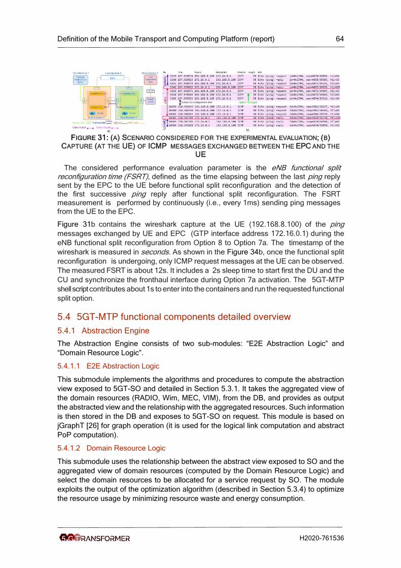
Definition of the Mobile Transport and Computing Platform (report) 64
H2020-761536
FIGURE 31: (A) SCENARIO CONSIDERED FOR THE EXPERIMENTAL EVALUATION; (B)
CAPTURE (AT THE UE) OF ICMP MESSAGES EXCHANGED BETWEEN THE EPC AND THE
UE
The considered performance evaluation parameter is the eNB functional split reconfiguration time (FSRT), defined as the time elapsing between the last ping reply sent by the EPC to the UE before functional split reconfiguration and the detection of
the first successive ping reply after functional split reconfiguration. The FSRT measurement is performed by continuously (i.e., every 1ms) sending ping messages
from the UE to the EPC.
Figure 31b contains the wireshark capture at the UE (192.168.8.100) of the ping
messages exchanged by UE and EPC (GTP interface address 172.16.0.1) during the
eNB functional split reconfiguration from Option 8 to Option 7a. The timestamp of the
wireshark is measured in seconds. As shown in the Figure 34b, once the functional split
reconfiguration is undergoing, only ICMP request messages at the UE can be observed.
The measured FSRT is about 12s. It includes a 2s sleep time to start first the DU and the
CU and synchronize the fronthaul interface during Option 7a activation. The 5GT-MTP
shell script contributes about 1s to enter into the containers and run the requested functional
split option.
5.4 5GT-MTP functional components detailed overview
5.4.1 Abstraction Engine
The Abstraction Engine consists of two sub-modules: “E2E Abstraction Logic” and
“Domain Resource Logic”.
5.4.1.1 E2E Abstraction Logic
This submodule implements the algorithms and procedures to compute the abstraction
view exposed to 5GT-SO and detailed in Section 5.3.1. It takes the aggregated view of
the domain resources (RADIO, Wim, MEC, VIM), from the DB, and provides as output
the abstracted view and the relationship with the aggregated resources. Such information
is then stored in the DB and exposes to 5GT-SO on request. This module is based on
jGraphT [26] for graph operation (it is used for the logical link computation and abstract
PoP computation).
5.4.1.2 Domain Resource Logic
This submodule uses the relationship between the abstract view exposed to SO and the
aggregated view of domain resources (computed by the Domain Resource Logic) and
select the domain resources to be allocated for a service request by SO. The module
exploits the output of the optimization algorithm (described in Section 5.3.4) to optimize
the resource usage by minimizing resource waste and energy consumption.
5GT-
MTP

Definition of the Mobile Transport and Computing Platform (report) 65
H2020-761536
5.4.2 Dispatcher
This module is the core of the application that handles the entire communication between
the 5GT-MTP modules. It is realized in a flexible way by using the event driven
programming obtained using the EventBus defined in the GUAVA library (3rd party open
source porting of android libraries in java) [27] and follows the “Event Driven Approach”
(EDA): each 5GT-MTP module publishes a list of events that is able to handle at the
bootstrap. Each event represents an operation performed by the module (it is
implemented as a Java method). The dispatcher collects all published events and expose
them to each module. In this way, when a module needs an operation executed by
another module, it posts the related event. The post is captured by the dispatcher and
sent to the modules handling the event. In more details, the list of events is collected in
a separated java package (“events”). All events are classic “Plain Old Java Object”
(POJO) grouped according the 5GT-MTP feature where such event can be invoked.
5.4.3 ResOrch
The module orchestrates the 5GT-MTP procedures among the controlled domains The
orchestrated procedures are the allocation/termination of the logical link (i.e. link
connecting DC gateway of two VIM that crosses one or more WIM) and the
allocation/termination of MEC application (that requires coordination between VIM and
MEC domain). The orchestration follows the sequence diagram described in IFA022 [29]
(first creates the connectivity inside the WIM and then stitches it with the DC gateway of
the VIM) and the workflow shown in Section 5.6.
5.4.4 DB
It is a common module used by the other components to retrieve abstraction, aggregation
and service information; in addition, it contains the AppD description of the MEC app
according to ETSI MEC 010-2 information model [31]. It is implemented as external SQL
server (mySQL [32] is used for generation) and the java class is just a front-end that
connects to the SQL server and handles all queries (e.g., insert entries, query to retrieve
parameters). 3rd party open source JDBC driver [32][31] is used to manage SQL
connections.
5.4.5 Local PA
It is a module that is invoked by the Resource Selection submodule to optimize the
placement of VM and the usage of networking resources. The module is responsible to
contact the optimization algorithm described in Section 5.3.4 5.3.4and provide the
algorithm results to the other module. A REST API is used for the communication
between this module and the optimization algorithm.
5.4.6 Monitoring driver
It is a module used to communicate with the 5GT Monitoring Platform (based on
Prometheus). It uses the monitoring interface exposed by the Monitoring Platform to
register itself to the platform, create performance monitoring jobs and get alert
notifications.
This module is responsible to require monitoring activities related to infrastructure
resources in terms of compute, storage networking, radio, and MEC and provides the
output of the monitoring platform to the module requiring the monitoring job.

Definition of the Mobile Transport and Computing Platform (report) 66
H2020-761536
5.5 5GT-MTP interfaces
5GT basically adopts ETSI IFA005 [33] as well as specific IFA005-oriented API
commands for the interfaces between 5GT-SO and 5GT-MTP and between 5GT-MTP
and VIMs/WIMs. In a nutshell, IFA005 defines standard interfaces to enable a consumer
block at the VIM north bound interface to retrieve information about resources capability
(e.g., maximum CPU), to allocate and reserve a resource, and to be notified about a
change of a resource.
For the monitoring, instead, the Prometheus monitoring platform has been adopted thus
the interfaces use the REST API provided by this platform.
The considered interfaces involve the following operations: query, allocation,
subscription, notification, termination and performance monitoring.
5.5.1 5GT-MTP NBI (5GT-SO SBI)
This interface is devised to provide the communication between both the 5GT-SO and
the 5GT-MTP building elements providing macroscopically the following set of
functionalities and/or operations:
i. Retrieving the abstracted information of the logical links (LLs) enabling the
connectivity between pairs of remote NFVI-PoPs. Indeed, the LL is a virtual
link abstracted from the underlying transport network infrastructure
interconnecting a pair of NFVI-PoPs’ Gws.
ii. Retrieving relevant information about each available NFVI-PoP not only about
specific attributes defining the NFVI-PoPs (e.g., location, identifier,
associated controller/VIMId, etc.) but also about the status of the cloud
resources encompassing memory, CPU and storage.
iii. Create (and terminate) the inter-NFVI-PoP connectivity (i.e., selecting the
resources such as bandwidth on the LLs) for a specific network service (which
is unambiguously determined by the serviced parameter).
iv. Create (and terminate) the intra-NFVI-PoP connectivity at each selected
NFVI-PoP, i.e., the connectivity between the VNFs to be instantiated and the
selected NFVI-PoP’s Gw (external network endpoint) to enable the
interconnection to other remote NFVI-PoPs.
v. Create (and terminate) VNFs on a given NFVI-PoPs.
All the above functionalities are supported over a specific pool of REST API messages
where the 5GT-MTP operates as the server and the 5GT-SO is the client. The content of
the messages is encoded using JSON format. The aim of the API is to feed the
Placement Algorithm (PA) executed at the 5GT-SO with the existing and updated
cloud/network infrastructure (entailing both NFVI-PoPs and LLs) to select and trigger the
allocation of the cloud and networking resources fulfilling the requirements of the
incoming network services.
For the sake of completeness, Figure 32 depicts the view at the 5GT-SO of the resources
being abstracted from the 5GT-MTP. As mentioned above, such a view is limited by
specific details of the pool of existing NFVI-PoPs with their supported cloud resources
(i.e., identifiers, type and status) as well as the set of inter-NFVI-PoP links (i.e., LLs). This
information constitutes the input for executing the 5GT-SO PA algorithm.

Definition of the Mobile Transport and Computing Platform (report) 67
H2020-761536
FIGURE 32: CLOUD/NETWORK VIEW AT THE 5GT-SO: NFVI-POPS AND LOGICAL LINKS
(LLS)
In the following, specific details (i.e., contents) of the different API messages supporting
those set of functionalities are provided.
5.5.1.1.1 Retrieval of NFVI-PoPs and inter-NFVI-PoP links information
This information is an on-demand basis collected by the 5GT-SO (e.g., whenever a 5GT-
SO PA should be executed to have the most updated view of the whole infrastructure)
via a GET method message where the required URI is set to /abstract-resources. The
request and response messages are named ComputeNetworkResourceRequest and
ComputenNetworkResourceResponse (see Figure 33), respectively.
FIGURE 33: REQUEST/RESPONSE 5GT-MTP NBI FOR RETRIEVAL OF CLOUD AND
NETWORK INFORMATION
The request message does not carry any content on the body, whilst a successful
response (code 200) provides the details of the NFVI-PoPs and inter-NFVI-PoP links
(i.e., LLs). In a nutshell, this information is presented and formatted in a hierarchical via
two top-level JSON arrays, namely:
a. NFVI-PoPs: providing the set of available NFVI-PoPs.
b. LogicalLinksInterNfviPops: providing the set of (unidirectional and/or
bidirectional) links connecting a particular pair of NFVI-PoPs.
5GT-SO 5GT-MTP
ComputeNetworkResourceRequest
ComputeNetworkResourceResponse
REST API GET Method
- No body information
HTTP/1.1
200 ok
Body:
- NfviPops
- logicalLinkInterNfviPops

Definition of the Mobile Transport and Computing Platform (report) 68
H2020-761536
NFVI-PoPs
As said before, this describes a top-level JSON encoding array where a component
provides the parameters and attributes related to a given NFVI-PoP. Note that some of
these attributes are already defined in [33]. Figure 34 shows a screenshot (via swagger
REST API editor [33]) of the defined NFVI-PoP array carried in the body of the response
message. The relevant attributes describing every NFVI-PoP element are:
• Geographical Location: information providing the location of the NFVI-PoP
• VimId: identifier of the VIM (NFVI-PoP controller)
• networkConnectivityEndopoints: set of NFVI-PoP’s Gw (IPv4 address) which are
the endpoints of the LLs enabling the inter-NFVI-PoP connectivity
• nfviPopId: identifier of the NFVI-PoP
• resourceZoneAttributes: set of attributes describing, in an aggregated manner,
the specific cloud resources supported by the NFVI-PoP
o zoneId: identifier for a specific resource zone segment of the NFVI-PoP
o zoneName: name for a specific resource zone segment of the NFVI-PoP
o zoneState: status of the specific resource zone segment of the NFVI-PoP
o zoneProperty: properties and capabilities associated to the resource zone
o metadata: allows adding other specific resource zone properties/details
o memoryResourceAttributes: object specifying the status of the
aggregated NFVI-PoP memory resource in terms of:
▪ availableCapacity, reservedCapacity, totalCapacity and
allocatedCapacity
o cpuResourceAttributes: object specifying the status of the aggregated
NFVI-PoP CPU resource in terms of:
▪ availableCapacity, reservedCapacity, totalCapacity and
allocatedCapacity
o storageResourceAttributes: object specifying the status of the aggregated
NFVI-PoP storage resource in terms of:
▪ availableCapacity, reservedCapacity, totalCapacity and
allocatedCapacity

Definition of the Mobile Transport and Computing Platform (report) 69
H2020-761536
FIGURE 34: 5GT-MTP NBI: GET METHOD WITH NFVI-POP ARRAY INFORMATION
LogicalLinksInterNfviPops
This provides a top-level JSON array where a single array component contains the
parameters and attributes related to each available LL. To better illustrate the defined LL
attributes, we rely on the Figure 35 to describe how every LL is identified and its
corresponding addressing values. As shown, a LL connects two NFVI-PoPs in a
unidirectional way. The data transmission direction (in the example from NFVI-PoP#1
towards NFVI-PoP#3), the LL is determined by a global logicalLinkId, and an
unnumbered link identifier. The unnumbered link identifier is formed by the tuple:
srcGwIPAddress and dstGwIPAddress which determines the IPv4 addresses of the
NFVI-PoP Gw endpoints (according to the data transmission direction); and the
localLinkId and remoteLinkId which are 32bit positive integers describing a specific link.
By doing so, observe that multiple LLs between the same pair of srcGwIPAddress and
dstGwIPAddress could be handled as long as localLinkId and remoteLinkId are different.
Last but not least, for doing a LL bidirectional, it is needed to add in the top-level array a
component describing the identifiers and attributes in the reverser data transmission
direction (in the example of Figure 35, from NFVI-PoP#3 towards NFVI-PoP#1). Note
that for this LL, previous identifiers for srcGwIPAddress (Gw#1), dstGwIPAddress,
(Gw#3), localLinkId (10000) and remoteLinkId (10000) are used by for defining the
reverse direction, that is following the example the srcGwIPAddress is set to the Gw#3,
dstGwIPAddress, is now Gw#1, and the same for localLinkId and remoteLinkId.

Definition of the Mobile Transport and Computing Platform (report) 70
H2020-761536
FIGURE 35: EXAMPLE OF THE IDENTIFIERS AND ADDRESSING OF A UNIDIRECTIONAL LL
Bearing in mind the above agreement for determining and specifying every created LL
carried into the LogicalLinksInterNfviPops array, the following set of attributes per each
LL is defined:
• LogicalLinkId: identifier used for determining a given LL
• totalBandwidth: total amount of bandwidth (in Mb/s) supported by the LL
• availableBandwidth: available bandwidth (in Mb/s) being not used on the LL
• networkQoS: object used to define a set of QoS parameters associated to the LL
o linkCost: metric used for selecting the LL (e.g., associated to length of the
LL)
o linkDelay: delay (in ms) associated to the LL
• srcGwIPAddress: IPv4 of the ingress NFVI-PoP’s Gw endpoint of the LL
• dstGwIPAddress: IPv4 of the egress NFVI-PoP’s Gw endpoint of the LL
• localLinkId: positive 32-bit integer value associated to the identifier of LL at the
source NFVI-PoP’s Gw
• remoteLinkId: positive 32-bit integer value associated to the identifier of LL at the
destination NFVI-PoP’s Gw
• networkLayer: supported network layer capabilities of the NFVI-PoP Gws (e.g.,
L2, L3)
• interNfviPopNetworkType: describes the network connectivity type (e.g., L2-
VPN, VXLAN, MPLS)
interNfviPopNetworkTopology: describes the network connectivity topology (e.g.,
point-to-point, mesh, tree)
Figure 36 shows a screenshot (via swagger REST API editor [33]) of the defined
logicalLinkInterNfviPops array carried in the body of the response message.
NFVI-
PoP#1
NFVI-
PoP#3Gw#1 Gw#3
localLinkId
(e.g., 10000)
remoteLinkId
(e.g., 10000)
srcGwIPAddress dstGwIPAddress
logicalLinkId

Definition of the Mobile Transport and Computing Platform (report) 71
H2020-761536
FIGURE 36: 5GT-MTP NBI: GET METHOD WITH LOGICALLINKINTERNFVIPOPARRAY
INFORMATION
5.5.1.1.2 Allocating (and terminating) inter-Nfvi-Pops Connectivity
This operation commanded by the 5GT-SO and processed by the 5GT-MTP triggers the
(de-)allocation of the network resources over a selected set of LLs used for deploying (/
releasing) a specific network service. The network resource allocation relies on the REST
POST method with the URI set to /abstract-network-resources, whereas the de-allocation
of the network resources on previously selected LLs uses the REST DELETE method
with the same URI.
Figure 37 shows the exchanged messages (i.e., interNfviPopConnectivityRequest and
interNfviPopConnectivityResponse) between the 5GT-SO and 5GT-MTP to allocate the
network resources (e.g., bandwidth) on a set of LLs being the output of the 5GT-SO PA
mechanism. In the request message body, the following information is carried to proceed
with the allocation in a set of LLs:
• LogicalLinkPathList: array containing a list of LLs where specific network
resources (e.g., bandwidth) should be allocated. For each LL, it is determined a
set of relevant identifiers and parameters:
o logicalLinkAttributes: object specifying a fixed set of the selected LL’s
attributes
▪ logicalLinkId: identifier used for determining a given LL
▪ srcGwIpAddress: IPv4 of the ingress NFVI-PoP’s Gw endpoint of
the LL
▪ dstGwIPAddress: IPv4 of the egress NFVI-PoP’s Gw endpoint of
the LL

Definition of the Mobile Transport and Computing Platform (report) 72
H2020-761536
▪ localLinkId: positive 32-bit integer value associated to the identifier
of LL at the source NFVI-PoP’s Gw
▪ remoteLinkId: positive 32-bit integer value associated to the
identifier of LL at the destination NFVI-PoP’s Gw
▪
o reqBandwidth: requested amount of bandwidth (in Mb/s) to be allocated
in a LL
o reqLatency: requested maximum tolerated latency (in ms) to be
guaranteed over an LL
o metadata: used to specify relevant information about the addressing of
the deployed VNFs at the NFVI-PoPs. This information will eventually
allow configuring and programming the network elements (e.g., packet
switches) forming the underlying inter-NFVI-PoP network infrastructure
(also referred to as WAN).
• networkLayer: supported network layer capabilities of the NFVI-PoP Gws (e.g.,
L2, L3, …)
• interNfviPopNetworkType: describes the network connectivity type (e.g., L2-
VPN, VXLAN, MPLS, etc.)
• metaData: used to specify the serviceId which is the identifier assigned by the
5GT-SO to unambiguously refer to a given network service. Observe that the
same serviceId needs to be used regardless of the LLs being traversed by the
network service. Moreover, other relevant information will be needed to be added
such as the assigned IP addresses of the VMs (hosting the targeted VNFs) at
each Nfvi-Pop. This information will allow the underlying WIM controllers
coordinated by the 5GT-MTP to configure the required flow matching rules for
transporting the data packets (e.g., sourced at a given VM and terminated at an
another VM of different Nfvi-Pops). Additionally, metaData would be also used for
carrying key information for supporting federation scenarios such as exchanging
the used VLAN ids between separated domains.
The above set of attributes contained into the body of the
interNfviPopConnectivityRequest message are shown in Figure 38 using the SWAGGER
REST API editor [33].
FIGURE 37: REQUEST/RESPONSE 5GT-MTP NBI FOR ALLOCATING RESOURCES ON A
SET OF LLS SELECTED BY THE 5GT-SO PA
5GT-SO 5GT-MTP
interNfviPopConnectivityRequest
interNfviPopConnectivityResponse
REST API POST Method
Body
- logicalLinkPathList (array)
- reqBandwidth
- reqLatency
- networkLayer
- interNfviPopNetworkType
- metaData
HTTP/1.1
201 Created
Body:
- interNfviPopConnecitivityId
- interNfviPopNetworkSegmentType
Key: serviceId
Value: Id
e.g., VLAN tag, etc.

Definition of the Mobile Transport and Computing Platform (report) 73
H2020-761536
FIGURE 38: 5GT-MTP NBI: REQUEST MESSAGE BODY FOR ALLOCATING A SET OF LLS
FOR A GIVEN NETWORK SERVICE (SERVICEID)
A successful REST API response sent from the 5GT-MTP to the 5GT-SO (i.e., response
code 201, Created) carries in the message body a top-level array indicating for each LL
information related to the allocated resource such as the connection identifier (used to
determine the data path over a given LL) and the so-called segment type (e.g., VLAN
tag) being used for transporting and forwarding the data traffic over a specific LL. In other
words, a network service which is determined by a serviceID may traverse n LLs. For
each LL, a specific connection identifier and a segment type (which may be different) are
used. Thus, at the 5GT-MTP, it is stored the serviceId and their associated n connection
identifiers (referred to as interNfviPopConnectivityId) and the segment types (herein
termed as interNfviPopNetworkSegmentType). Those objects are described below:
• interNfviPopConnectivityId: Identifier used for determining a connectivity for a
given serviceId over a particular LL
• interNfviPopNetworkSegmentType: network selector type used to switch and
forward the traffic of a given serviceId over a particular LL
The above set of attributes contained into the body of the
interNfviPopConnectivityRespose message are shown in Figure 39 using the
SWAGGER REST API editor [33].

Definition of the Mobile Transport and Computing Platform (report) 74
H2020-761536
FIGURE 39: 5GT-MTP NBI: RESPONSE MESSAGE BODY FOR ALLOCATING A SET OF LLS
FOR A GIVEN NETWORK SERVICE (SERVICEID)
To complete the management of the inter-NFVI-PoP link resources, below we also
provide details for releasing such network resources when a network service is being
terminated. Figure 40 provides the pair of exchanged messages between the 5GT-SO
and the 5GT-MTP for de-allocating the LL’s resources associated to a given serviceID.
These messages are: deleteNfviPopConnectivityRequest and
deleteNfviPopConnectivityResponse. The request message body carries the serviceID
in the so-called interNfviPopConnectivityId object. Additionally, a metadata object
provides a placeholder for contents being considered in potential new uses. The
response message does not require body information/details.
FIGURE 40: REQUEST/RESPONSE 5GT-MTP NBI FOR REMOVING THE INTER-NFVI-POP
RESOURCES RELATED TO A SPECIFIC SERVICEID
The content of the body forming the deleteNfviPopConnectivityRequest message are
shown in Figure 41 using the SWAGGER REST API editor [33].
5GT-SO 5GT-MTP
deleteNfviPopConnectivityRequest
deleteNfviPopConnectivityResponse
REST API DELETE Method
Body
- interNfviPopConnecitivityId
- metaData
HTTP/1.1
204 ok
Body:
- No body info

Definition of the Mobile Transport and Computing Platform (report) 75
H2020-761536
FIGURE 41: 5GT-MTP NBI: REQUEST MESSAGE BODY FOR DE-ALLOCATING ALL
NETWORK RESOURCES ASSOCIATED TO A GIVEN SERVICEID
Those objects are described below:
• interNfviPopConnectivityIdList: It is an array of the interNfviConnectivityIds used
by a particular serviceId to be removed
o InterNfviPopConnectivityId: Identifier used for determining a connectivity
for a given serviceId over a particular LL
• metaData: contents not defined at the time being but reserved for future uses.
5.5.1.1.3 Allocating (and terminating) intra-Nfvi-Pop Connectivity
The allocation of the intra-NFVI-PoP connectivity entails the deployment of all the
required subnets and networks to enable the connectivity of the VNFs to be instantiated
into a specific NFVI-PoP. For instance, the outcome of doing that is to provide the IP
address being assigned to the VNF, determining the L2-VPN labels / tags for forwarding
data traffic, the connectivity between the VNF port and the NFVI-PoP’s Gw for the
external connectivity towards the WAN, etc. To this end, it is necessary that at the time
of deploying a network service, once the NFVI-PoPs are selected to host the required
VNFs, the corresponding subnets and networks are created. This operation should be
triggered by the 5GT-SO using the pair of messages AllocateNetworkResourceRequest
and AllocateNetworkResourceResponse. The former is attained using REST POST
method with the URI set to /network_resources. Figure 42 shows the exchanged
messages between the 5GT-SO and 5GT-MTP to create the intra-NFVI-PoP connectivity
where eventually the targeted VNFs should be instantiated. The contents of the
AllocateNetworkResourceRequest are those already specified in [33]. Likewise, the
successful reply message (i.e., AllocateNetworkResourceResponse) contains the set of
parameters defined in [33]. For the sake of brevity and since those contents are not
extended to cover specific 5GT architectural needs, the interested reader is invited to
refer to the above ETSI IFA 005 document [33].

Definition of the Mobile Transport and Computing Platform (report) 76
H2020-761536
FIGURE 42: REQUEST/RESPONSE 5GT-MTP NBI FOR CREATING THE INTRA-NFVI-POP
CONNECTIVITY
Moreover, the metaData contents typically defined in the IFA005 messages is exploited
to carry relevant information for the configuration of the intraNfviPop network resources.
This includes:
• serviceId: the identifier assigned by the 5GT-SO to unambiguously determine the
network service being deployed within the Nfvi-Pop location
• nfviPopId: identifier of the NFVI-PoP
• floating_required: this parameter is used to eventually indicate the VIM controller
(e.g., OpenStack) that the allocation of the IP addressing of the intra-Nfvi-Pop
network is assigned according to a floating IP assignment mode.
The termination of the intra-NFVI-PoP connectivity is attained using the pair of messages
defined in [33]. The contents and parameters carried into those messages are thoroughly
addressed in the above reference.
5.5.1.1.4 Allocating (and terminating) compute resources
Requests “allocating/terminating compute resources” are used for the creation and
termination of compute resources on the underlying VIM. This request is sent from the
5GT-SO to the 5GT-MTP. The 5GT-MTP interacts through the deployed 5GT-MTP plugin
with the VIM controlling a specific NFVI-PoP. The request and response messages body
contain the parameters reported in ETSI GS NFV-IFA 005 specification for the
Allocate/Terminate Virtualised Compute Resource operation. Requests “allocating
compute resources” contain the information about memory, CPU and disk resources
(e.g., available, etc.), a list of elements defining the affinity or anti affinity, network
interfaces, software image, list of metadata containing key-value pairs and location
constraints. The request body is detailed below in Figure 43.
5GT-SO 5GT-MTP
allocateNetworkResourceRequest
AllocateNetworkResourceResponse
REST API DELETE Method
Body (ETSI IFA 005)
- …
- networkResourceName
- …
HTTP/1.1
201 ok
Body:
- (ETSI IFA 005)

Definition of the Mobile Transport and Computing Platform (report) 77
H2020-761536
FIGURE 43: REQUEST/RESPONSE FOR ALLOCATION COMPUTE RESOURCES
AllocatingComputeResources request uses URL prefix /abstract-network-resources
request body. The example of the request body is described in the Figure 44:

Definition of the Mobile Transport and Computing Platform (report) 78
H2020-761536
FIGURE 44: EXAMPLE OF THE COMPUTE ALLOCATION REQUEST BODY
Compute allocation request can contain a variety of fields to configure allocated compute
resources accordingly. Compute allocation request parameters are described as follows:
• affinityOrAntiAffinityConstraints A list of elements with affinity or anti affinity
information of the virtualised compute resource to allocate. There should be a
relation between the constraints defined in the different elements of the list.
• affinityAntiAffinityResourceGroup Identifier of the producer-managed group of
virtualised resources with which the actual resource is requested to be affine or
anti-affine. Either affinityAntiAffinityResourceList or
affinityAntiAffinityResourceGroup but not both shall be present.
• affinityAntiAffinityResourceList Consumer-managed list of identifiers of
virtualised resources with which the actual resource is requested to be affine or
anti-affine. Either affinityAntiAffinityResourceList or
affinityAntiAffinityResourceGroup but not both shall be present. List of identifiers
of virtualised resources.
• scope Qualifies the scope of the constraint. In case of compute resource: e.g.
"NFVI-PoP" or "NFVI Node". In case of ports: e.g. "virtual switch or router" or
{ "affinityOrAntiAffinityConstraints": [ { "affinityAntiAffinityResourceGroup": "string", "affinityAntiAffinityResourceList": { "resource": [ "string" ] }, "scope": "string", "type": "string" } ], "computeFlavourId": "string", "computeName": "string", "interfaceData": [ { "ipAddress": "string", "macAddress": "string" } ], "locationConstraints": "string", "metadata": [ { "key": "string", "value": "string" } ], "reservationId": "string", "resourceGroupId": "string", "userData": { "content": "string",
"method": "string" },
"vcImageId": "string" }

Definition of the Mobile Transport and Computing Platform (report) 79
H2020-761536
"physical NIC", or "physical network" or "NFVI Node". In case of networks: e.g.
"physical NIC", "physical network" or "NFVI Node". In case of subnets: it should
be ignored. Defaults to "NFVI Node" if absent.
• type Indicates whether this is an affinity or anti-affinity constraint.
• computeFlavourId Identifier of the Compute Flavour that provides information
about the particular memory, CPU and disk resources for virtualised compute
resource to allocate. The Compute Flavour is created with Create Compute
Flavour operation
• computeName Name provided by the consumer for the virtualised compute
resource to allocate. It can be used for identifying resources from consumer side.
• interfaceData The data of network interfaces which are specific to a Virtual
Compute Resource instance.
• ipAddress The virtual network interface can be configured with specific IP
address(es) associated to the network to be attached to. The cardinality can be 0
in the case that a network interface is created without being attached to any
specific network, or when an IP address can be automatically configured, e.g. by
DHCP.
• macAddress The MAC address desired for the virtual network interface. The
cardinality can be 0 to allow for network interface without specific MAC address
configuration.
• locationConstraints If present, it defines location constraints for the resource(s) is
(are) requested to be allocated, e.g. in what particular Resource Zone.
• metadata List of metadata key-value pairs used by the consumer to associate
meaningful metadata to the related virtualised resource.
• reservationId Identifier of the resource reservation applicable to this virtualised
resource management operation. Cardinality can be 0 if no resource reservation
was used.
• resourceGroupId Unique identifier of the "infrastructure resource group", logical
grouping of virtual resources assigned to a tenant within an Infrastructure
Domain.
• userData Element containing user data to customize the virtualised compute
resource at boot-time.
• content String containing the user data to customize a virtualised compute
resource at boot-time.
• method is used as transportation media to convey the content of the UserData to
the virtualised compute resource. Possible values: CONFIG-DRIVE.
• vcImageId Identifier of the virtualisation container software image (e.g. a virtual
machine image). Cardinality can be 0 if an "empty" virtualisation container is
allocated.
Successfully responding the processed request, the 5GT-MTP creates a response code
201 and returns it to SO. The response body example is shown on the Figure 45.

Definition of the Mobile Transport and Computing Platform (report) 80
H2020-761536
FIGURE 45: EXAMPLE OF THE COMPUTE ALLOCATION RESPONSE BODY
The compute allocation response contains the following fields:
• accelerationCapability Selected acceleration capabilities (e.g. crypto, GPU) from
the set of capabilities offered by the compute node acceleration resources. The
cardinality can be 0, if no particular acceleration capability is provided.
• computeId Identifier Identifier of the virtualised compute resource.
• computeName Name of the virtualised compute resource.
• flavourId Identifier of the given compute flavour used to instantiate this virtual
compute.
• hostId Identifier of the host the virtualised compute resource is allocated on.
{ "accelerationCapability": [ "string" ], "computeId": "string", "computeName": "string", "flavourId": "string", "hostId": "string", "operationalState": "string", "vcImageId": "string", "virtualCpu": { "cpuArchitecture": "string", "cpuClock": 0, "numVirtualCpu": 0, "virtualCpuOversubscriptionPolicy": "string", "virtualCpuPinning": { "cpuMap": "string", "cpuPinningPolicy": "string", "cpuPinningRules": "string" } }, "virtualDisks": "string", "virtualMemory": { "numaEnabled": true, "virtualMemOversubscriptionPolicy": "string", "virtualMemSize": 0 }, "virtualNetworkInterface": [ { "accelerationCapability": "string", "bandwidth": "string", "ipAddress": "string", "macAddress": "string", "metadata": "string", "networkId": "string", "networkPortId": "string", "operationalState": "string", "ownerId": "string", "resourceId": "string", "typeConfiguration": "string", "typeVirtualNic": "string" } ], "zoneId": "string" }

Definition of the Mobile Transport and Computing Platform (report) 81
H2020-761536
• operationalState Operational state of the compute resource.
• vcImageId Identifier of the virtualisation container software image (e.g. virtual
machine image). Cardinality can be 0 if an "empty" virtualisation container is
allocated.
• virtualCpu The virtual CPU(s) of the virtualised compute.
• cpuArchitecture CPU architecture type. Examples are x86, ARM.
• cpuClock Minimum CPU clock rate (e.g. in MHz) available for the virtualised CPU
resources.
• numVirtualCpu Number of virtual CPUs.
• virtualCpuOversubscriptionPolicy The CPU core oversubscription policy, e.g. the
relation of virtual CPU cores to physical CPU cores/threads. The cardinality can
be 0 if no policy has been defined during the allocation request.
• virtualCpuPinning The virtual CPU pinning configuration for the virtualised
compute resource.
• cpuMap Shows the association of virtual CPU cores to physical CPU cores.
• cpuPinningPolicy The policy can take values of "static" or "dynamic". In case of
"static" the virtual CPU cores have been allocated to physical CPU cores
according to the rules defined in cpuPinningRules. In case of "dynamic" the
allocation of virtual CPU cores to physical CPU cores is decided by the VIM.
• cpuPinningRules A list of rules that should be considered during the allocation of
the virtual CPUs to physical CPUs in case of "static" cpuPinningPolicy.
• virtualDisks Element with information of the virtualised storage resources
(volumes, ephemeral that are attached to the compute resource.)
• virtualMemory The virtual memory of the compute.
• numaEnabled It specifies the memory allocation to be cognisant of the relevant
process/core allocation.
• virtualMemOversubscriptionPolicy The memory core oversubscription policy in
terms of virtual memory to physical memory on the platform. The cardinality can
be 0 if no policy has been defined during the allocation request.
• virtualMemSize Amount of virtual Memory (e.g. in MB).
• virtualNetworkInterface Element with information of the instantiated virtual
network interfaces of the compute resource.
• accelerationCapability It specifies if the virtual network interface requires certain
acceleration capabilities.The cardinality can be 0, if no particular acceleration
capability is provided.
• bandwidth The bandwidth of the virtual network interface (in Mbps).
• ipAddress The virtual network interface can be configured with specific IP
address(es) associated to the network to be attached to. The cardinality can be 0
in the case that a network interface is created without being attached to any
specific network, or when an IP address can be automatically
• configured, e.g. by DHCP.
• macAddress The MAC address of the virtual network interface.
• metadata KeyValuePair List of metadata key-value pairs used by the consumer
to associate meaningful metadata to the related virtualised resource.
• networkId (Reference to VirtualNetwork) In the case when the virtual network
interface is attached to the network, it identifies such a network. The cardinality
can be 0 in the case that a network interface is created without being attached to
any specific network.
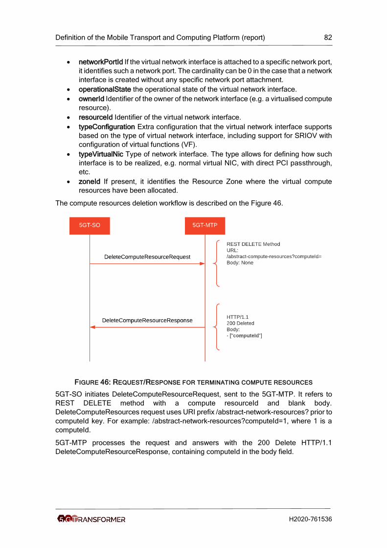
Definition of the Mobile Transport and Computing Platform (report) 82
H2020-761536
• networkPortId If the virtual network interface is attached to a specific network port,
it identifies such a network port. The cardinality can be 0 in the case that a network
interface is created without any specific network port attachment.
• operationalState the operational state of the virtual network interface.
• ownerId Identifier of the owner of the network interface (e.g. a virtualised compute
resource).
• resourceId Identifier of the virtual network interface.
• typeConfiguration Extra configuration that the virtual network interface supports
based on the type of virtual network interface, including support for SRIOV with
configuration of virtual functions (VF).
• typeVirtualNic Type of network interface. The type allows for defining how such
interface is to be realized, e.g. normal virtual NIC, with direct PCI passthrough,
etc.
• zoneId If present, it identifies the Resource Zone where the virtual compute
resources have been allocated.
The compute resources deletion workflow is described on the Figure 46.
FIGURE 46: REQUEST/RESPONSE FOR TERMINATING COMPUTE RESOURCES
5GT-SO initiates DeleteComputeResourceRequest, sent to the 5GT-MTP. It refers to
REST DELETE method with a compute resourceId and blank body.
DeleteComputeResources request uses URI prefix /abstract-network-resources? prior to
computeId key. For example: /abstract-network-resources?computeId=1, where 1 is a
computeId.
5GT-MTP processes the request and answers with the 200 Delete HTTP/1.1
DeleteComputeResourceResponse, containing computeId in the body field.

Definition of the Mobile Transport and Computing Platform (report) 83
H2020-761536
5.5.2 5GT-MTP SBI
The 5GT-MTP SBI enables the interaction between the 5GT-MTP and its managed VIM,
WIM, Radio and MEC domains. The following set of functionalities and/or operations are
provided for each domain type:
• VIM domain
i. Retrieving information about each available NFVI-PoP.
ii. Retrieving the available Resource Zones for each NFVI-PoP.
iii. Retrieving information about the various types of virtualised compute
resources (memory, CPU and storage) managed by the VIM.
iv. Retrieving capacity information for the various types of consumable
virtualised compute resources managed by the VIM.
v. Create (and terminate) VNFs on a given NFVI-PoP.
vi. Create (and terminate) an intra-PoP connectivity on a given NFVI-PoP.
• WIM domain
i. Retrieving information about edge gateways and virtual links managed by
the WIM.
ii. Create (and terminate) an intra-WIM connectivity between two edge
gateways.
• Radio domain
i. Retrieving information about the radio coverage area.
ii. Create (and terminate) radio network function
• MEC domain
i. Retrieving information about MEC regions (e.g., ID, delay).
ii. Create (and terminate) MEC app.
All the above functionalities are supported over a specific pool of REST API messages
encoded in JSON format where each domain operates as a server and the 5GT-MTP is
the client.
In the following sections, specific details of the different API messages supporting those
set of functionalities are provided.
5.5.2.1 VIM specific operations and functionalities
In this section VIM specific operations and functionalities are described. The
implementation of such operations and functionalities are based on ETSI GS NFV-IFA
005 specification [33].
5.5.2.1.1 Retrieval of NFVI-PoPs information
This information is an on-demand basis collected by the 5GT-MTP via a GET method
message where the required URI is set to /compute_resources
/nfvi_pop_compute_information. The request and response messages are named
QueryComputeNFVIPoP and QueryComputeNFVIPoP (see Figure 47), respectively.
The request message does not carry any content on the body, whilst a successful
response (code 200) provides the details of the NFVI-PoPs (NFVIPoP List) described as
a JSON encoding array where a component provides the attributes related to a given
NFVI-PoP. Figure 48 shows a screenshot (via swagger REST API editor [33]) of the
defined array carried in the body of the response message. The attributes describing
each NFVI-PoP element are:
• nfviPopId: Identifier of the NFVI-PoP.

Definition of the Mobile Transport and Computing Platform (report) 84
H2020-761536
• vimId: Identifier of the VIM.
• geographicalLocationInfo: Information about the geographic location (e.g.
geographic coordinates or address of the building, etc.) of the NFVI resources
that the VIM manages.
• networkConnectivityEndpoint: Information about network connectivity endpoints
(gateways) of the NFVI-PoP.
FIGURE 47: REQUEST/RESPONSE 5GT-MTP SBI FOR RETRIEVAL OF NFVI-POPS
INFORMATION
FIGURE 48: GET METHOD WITH NFVI-POPS INFORMATION
5.5.2.1.2 Retrieval of available resource zones
This information is collected upon on-demand basis by the 5GT-MTP via a GET method
message where the required URI is set to /compute_resources/resource_zones. The
request and response messages are named QueryComputeZone and
QueryComputeZoneResponse (see Figure 49), respectively. The request message does
not carry any content on the body, whilst a successful response (code 200) provides the
details of the Resource Zones (Zone List) described as a JSON encoding array where a
component provides the attributes related to a given Resource Zone. Figure 50 shows a
screenshot of the defined array carried in the body of the response message. The
attributes describing each Resource Zone element are:
• zoneId: Identifier of the Resource Zone.
• zoneName: Name of the Resource Zone.
• zoneState: Current state of the Resource Zone.
• nfviPopId: Identifier of the NFVI-PoP the Resource Zone belongs to.

Definition of the Mobile Transport and Computing Platform (report) 85
H2020-761536
• zoneProperty: Set of properties that define the capabilities associated to the
Resource Zone (e.g. low performance, acceleration capabilities, etc.).
• metadata: Metadata associated to the Resource Zone.
FIGURE 49: REQUEST/RESPONSE 5GT-MTP SBI FOR RETRIEVAL OF RESOURCE ZONES
INFORMATION
FIGURE 50: GET METHOD WITH RESOURCE ZONES INFORMATION
5.5.2.1.3 Retrieval of available virtualised compute resources
This information is an on-demand basis collected by the 5GT-MTP via a GET method
message where the required URI is set to /compute_resources/information. The request
and response messages are named QueryComputeResourceInformation and
QueryComputeResourceInformationResponse (see Figure 51), respectively. The
request message includes the zoneID in the URL as query string, which identifies the
resource zone for which the virtualised compute resources are requested. A successful
response (code 200) provides the details of the Virtualised Compute Resources
(Compute Resource List) described as a JSON encoding array where a component
provides the attributes related to a given Virtualised Compute Resource (virtualCPU or
virtualMemory). Figure 52 shows a screenshot of the defined array carried in the body of

Definition of the Mobile Transport and Computing Platform (report) 86
H2020-761536
the response message. The attributes describing the virtualCPU and virtualMemory
resources are:
• virtualCPU
o cpuArchitecture: CPU architecture type (e.g., x86, ARM, etc.)
o numVirtualCpu: Number of virtual CPUs.
o cpuClock: Minimum CPU clock rate (e.g. in MHz) available for the
virtualised CPU resources.
o virtualCpuOversubscriptionPolicy: CPU core oversubscription policy, e.g.
the relation of virtual CPU cores to physical CPU cores/threads.
o virtualCpuPinningSupported: It defines whether CPU pinning capability is
available on the consumable virtualised compute resource.
• virtualMemory
o virtualMemSize: Amount of virtual memory (e.g. in MB).
virtualMemOversubscriptionPolicy: Memory core oversubscription policy
in terms of virtual memory to physical memory on the platform.
numaSupported: It specifies if the memory allocation can be aware of the
relevant process/core allocation.
FIGURE 51: REQUEST/RESPONSE 5GT-MTP SBI FOR RETRIEVAL OF VIRTUALISED
COMPUTE RESOURCES INFORMATION

Definition of the Mobile Transport and Computing Platform (report) 87
H2020-761536
FIGURE 52: GET METHOD WITH VIRTUALISED COMPUTE RESOURCES INFORMATION
5.5.2.1.4 Retrieval of compute capacity information
This information is retrieved upon on-demand basis by the 5GT-MTP via a GET method
message where the required URI is set to /compute_resources/capacities. The request
and response messages are named QueryComputeCapacity and
QueryComputeCapacityResponse (see Figure 53), respectively. The request message
includes the ResourceTypeId in the URL as query string, which identifies the specific
Virtualised Compute Resource (virtualCPU or virtualMemory) for which the capacity
information is requested. A successful response (code 200) provides the capacity
information of the specific Virtualised Compute Resource (virtualCPU or virtualMemory)
described as a list of attributes in JSON format. Figure 54 shows a screenshot of the
attributes carried in the body of the response message. The attributes describing the
Capacity Information are:
• availableCapacity: Capacity available for allocation and reservation.
• reservedCapacity: Amount of reserved capacity.
• totalCapacity: Amount of total capacity.
• allocatedCapacity: Amont of allocated capacity.

Definition of the Mobile Transport and Computing Platform (report) 88
H2020-761536
FIGURE 53: REQUEST/RESPONSE 5GT-MTP SBI FOR RETRIEVAL OF COMPUTE
CAPACITY INFORMATION
FIGURE 54: GET METHOD WITH COMPUTE CAPACITY INFORMATION
5.5.2.1.5 VNF instantiation/termination
This operation requested by the 5GT-MTP and processed by a VIM domain triggers the
instantiation/termination of a VNF on a given NFVI-PoP. The instantiation of a VNF relies
on the REST POST method with the URI set to /compute_resources, whereas the
termination of a VNF uses the REST DELETE method with the same URI.
Figure 55 shows the exchanged messages (i.e., VnfInstatiationRequest and
VnfInstatiationResponse) between the 5GT-MTP and a specific VIM domain to
instantiate a VNF. The request and response messages body contain the attributes
reported in ETSI GS NFV-IFA 005 specification for the Allocate Virtualised Compute
Resource operation. The metadata attribute is used to specify the identifier of the NFV-
NS (serviceId) for which the VNF is instantiated.
Figure 56 shows the exchanged messages (i.e., VnfTerminationRequest and
VnfTerminationResponse) between the 5GT-MTP and a specific VIM domain to
terminate a VNF. The request and response messages contain the attributes reported in
ETSI GS NFV-IFA 005 specification for the Terminate Virtualised Compute Resource
operation. Specifically, the request message includes the computeId in the URL as query
string, which identifies the specific VNF to terminate. A successful response (code 200)
contains the identifier (computeId) of the VNF correctly terminated.

Definition of the Mobile Transport and Computing Platform (report) 89
H2020-761536
FIGURE 55: REQUEST/RESPONSE 5GT-MTP SBI FOR INSTANTIATION OF A VNF
FIGURE 56: REQUEST/RESPONSE 5GT-MTP SBI FOR TERMINATION OF A VNF
5.5.2.1.6 Intra-NFVI-PoP connectivity instantiation/termination
This operation requested by the 5GT-MTP and processed by a VIM domain triggers the
instantiation/termination of an intra-NFVI-PoP connectivity. The instantiation of an intra-
NFVI-PoP connectivity relies on the REST POST method with the URI set to
/network_resources, whereas the termination uses the REST DELETE method with the
same URI.
Figure 57 shows the exchanged messages (i.e., IntraPopNetworkInstatiationRequest
and IntraPopNetworkInstatiationResponse) between the 5GT-MTP and a specific VIM
domain to instantiate an intra-NFVI-PoP connectivity. The request and response
message bodies contain the attributes reported in ETSI GS NFV-IFA 005 specification to
support the Allocate Virtualised Network Resource operation. The metadata attribute is
used to specify the identifier of the NFV-NS (serviceId) for which the intra-NFVI-PoP
connectivity is instantiated.
Figure 58 shows the exchanged messages (i.e., IntraPopNetworkTerminationRequest
and IntraPopNetworkITerminationResponse) between the 5GT-MTP and a specific VIM
domain to terminate an intra-PoP connectivity. The request and response messages
contain the attributes reported in ETSI GS NFV-IFA 005 specification to support the
Terminate Virtualised Network Resource operation. Specifically, the request message
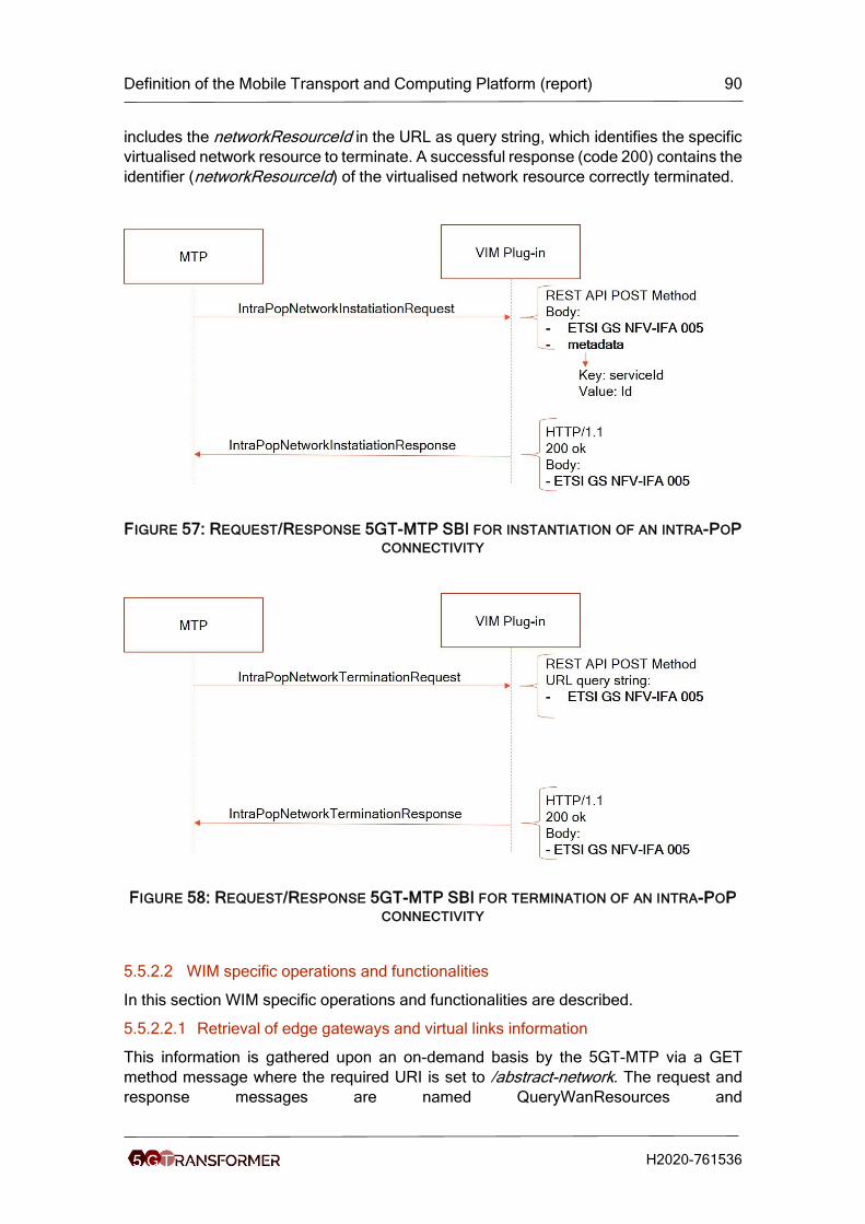
Definition of the Mobile Transport and Computing Platform (report) 90
H2020-761536
includes the networkResourceId in the URL as query string, which identifies the specific
virtualised network resource to terminate. A successful response (code 200) contains the
identifier (networkResourceId) of the virtualised network resource correctly terminated.
FIGURE 57: REQUEST/RESPONSE 5GT-MTP SBI FOR INSTANTIATION OF AN INTRA-POP
CONNECTIVITY
FIGURE 58: REQUEST/RESPONSE 5GT-MTP SBI FOR TERMINATION OF AN INTRA-POP
CONNECTIVITY
5.5.2.2 WIM specific operations and functionalities
In this section WIM specific operations and functionalities are described.
5.5.2.2.1 Retrieval of edge gateways and virtual links information
This information is gathered upon an on-demand basis by the 5GT-MTP via a GET
method message where the required URI is set to /abstract-network. The request and
response messages are named QueryWanResources and

Definition of the Mobile Transport and Computing Platform (report) 91
H2020-761536
QueryWanResourcesResponse (see Figure 59), respectively. The request message
does not carry content on the body, whilst a successful response (code 200) provides
the details of WAN aggregated resources (gateways and virtualLinks) described as two
JSON encoding array where a component provides the attributes related to a given
element. Figure 60 shows a screenshot (via swagger REST API editor [33]) of the defined
array carried in the body of the response message. The attributes describing gateway
and virtual-link elements are:
• Gateway
o geographicalLocationInfo: information about the geographic location (e.g.
geographic coordinates or address of the building, etc.) of the NFVI
resources that the WIM manages.
o wimId: Identification of the WIM.
o networkConnectivityEndpoint (array)
▪ netGwIpAddress: Edge gateway IP address.
▪ netGwInterfceId: References the edge gateway interface over
which the WAN is reachable.
o gatewayId: Identifier of the edge gateway.
• virtualLink
o virtualLinkId: Identifier of the virtual link.
o totalBandwidth: total bandwidth of the virtual link (in Mbps).
o availableBandwidth: available bandwidth of the virtual link (in Mbps).
o networkQoS
▪ linkCostValue: Cost of the virtual link.
▪ linkDelayValue: Delay of the virtual link.
▪ packetLossRate: Packet loss rate of the virtual link.
o srcGwId: References the source edge gateway.
o srcLinkId: References the source edge gateway interface.
o dstGwId: References the destination edge gateway.
o dstLinkId: References the destination edge gateway interface.
o networkLayer: Describes the network layer capabilities of the gateway,
i.e., Layer 2 (L2) or Layer 3 (L3), e.g. Ethernet, IP, IP/MPLS [29]

Definition of the Mobile Transport and Computing Platform (report) 92
H2020-761536
FIGURE 59: REQUEST/RESPONSE 5GT-MTP SBI FOR RETRIEVAL OF WAN
AGGREGATED RESOURCES INFORMATION
FIGURE 60: GET METHOD WITH WAN AGGREGATED RESOURCES INFORMATION

Definition of the Mobile Transport and Computing Platform (report) 93
H2020-761536
5.5.2.2.2 Intra-WIM connectivity instantiation/termination
This operation requested by the 5GT-MTP and processed by a WIM domain triggers the
instantiation/termination of an intra-WIM connectivity. The instantiation of an intra-WIM
connectivity relies on the REST POST method with the URI set to /network_resources,
whereas the termination uses the REST DELETE method with the same URI.
Figure 61 shows the exchanged messages (i.e., IntraWimNetworkInstatiationRequest
and IntraWimNetworkInstatiationResponse) between the 5GT-MTP and a specific WIM
domain to instantiate a WIM connectivity. Figure 62 shows a screenshot of the attributes
carried in the body of the request message. As shown in Figure 61, the metadata attribute
is used to specify the identifier of the NFV-NS (serviceId) for which the virtualised network
resource is instantiated.
The attributes of the request message are described below:
• locationConstraints: it defines location constraints for the resource(s) is (are)
requested to be allocated, e.g. in what particular Resource Zone.
• reservationId: Identifier of the resource reservation applicable to this virtualised
resource management operation.
• typeNetworkData: The network data provides information about the particular
virtual network resource to create.
• affinityOrAntiAffinityConstraints: A list of elements with affinity or anti affinity
information of the virtualised network resource to allocate.
• typeNetworkPortData: Information about the particular network port to create.
• resourceGroupId: Unique identifier of a logical group of virtual resources
assigned to a tenant within the WIM domain.
• metadata: List of metadata key-value pairs used by the consumer to associate
meaningful metadata to the related virtualised resource.
• networkResourceType: Type of virtualised network resource. Possible values
are: "network", "subnet" or network-port.
• networkResourceName: Name provided by the consumer for the virtualised
network resource to allocate.
• typeSubnetData: Information about the particular sub-network resource to create.
• bandwidth: Minimum virtual network bandwidth (in Mbps).
• delay: virtual network delay.
• networkType: Type of network that maps to the virtualised network, e.g., "local",
"vlan", "vxlan", "gre", "l3-vpn", etc.
• segmentType: Isolated segment for the virtualised network. For instance, for a
vlan networkType, it corresponds to the vlan identifier; and for a gre networkType,
this corresponds to a gre key.
• networkQoS: Information about QoS attributes that the network must support
• isShared: It defines whether the virtualised network is shared among consumers.
• sharingCriteria: Sharing criteria (if any) for this network.
• layer3Attributes: This attribute allows setting up a network providing defined layer
3 connectivity.
• portType: Type of network port, e.g., regular port, trunk port, etc.
• networkId: Identifier of the network that the port belongs to
• segmentId: The isolated network segment the port belongs to. For instance, for a
VLAN, it corresponds to the VLAN tag/identifier.

Definition of the Mobile Transport and Computing Platform (report) 94
H2020-761536
• ingressPointIPAddress: The ingress point IP address.
• ingressPointPortAddress: The ingress point port (interface) address.
• egressPointIPAddress: The egress point IP address.
• egressPointPortAddress: The egress point port (interface) address.
• wanLinkId: Identifier of the logical link.
Figure 61 shows the exchanged messages (i.e., IntraWimNetworkTerminationRequest
and IntraWimNetworkTerminationResponse) between the 5GT-MTP and a specific WIM
domain to terminate a WIM connectivity. The request message includes the networkId in
the URL as query string, which identifies the specific virtualised network resource to
terminate. Similarly, a successful response (code 200) contains the identifier (networkId)
of the virtualised network resource successfully terminated.
FIGURE 61: REQUEST/RESPONSE 5GT-MTP SBI FOR INSTANTIATION OF WAN
NETWORK RESOURCE

Definition of the Mobile Transport and Computing Platform (report) 95
H2020-761536
FIGURE 62: POST METHOD INPUT PARAMETERS
FIGURE 63: POST METHOD OUTPUT PARAMETERS
FIGURE 64: REQUEST/RESPONSE 5GT-MTP SBI FOR TERMINATION OF WAN NETWORK
RESOURCE

Definition of the Mobile Transport and Computing Platform (report) 96
H2020-761536
5.5.3 MEC SBI
This section presents the interface exposed by the MEC 5GT-MTP plugin. The MEC
plugin aims to abstract the operation of the MEC platform with respect to traffic rule
management, DNS handling, and MEC service dependencies. It should be noted that
the MEC plugin does not manage application instances. It is assumed that the
interactions with the underlying VIM with respect to their onboarding, instantiation, and
other lifecycle management operations are handled by the VIM plugin, as would be the
case if the instance was a regular VNF.
The MEC plugin provides a REST HTTP interface to the 5GT-MTP, which is specified
using OpenAPI v2.0 [35]. This API implements the following functions:
1. List MEC service requests per region
2. List MEC service requests across all regions
3. Create a MEC service request
4. Delete a MEC service request
5. Retrieve information about a specific service request
Figure 65 shows the API endpoints of the MEC plugin, including information on the HTTP
method used and the path for each function.
FIGURE 65: AVAILABLE MEC PLUGIN REST API CALLS
The MEC plugin is implemented in python and is based on the flask library. On its SBI, it
communicates with the MEC platform managing each region’s MEC over the MEP’s
REST API. In practice, the MEC plugin translates specific information elements included
in a MEC service request from a format that complies with ETSI MEC 10-2 to a format
compatible with the MEP’s API for service registration and discovery, and traffic and DNS
rule management. In particular, the MEC plugin receives with a MEC service request,
specific information elements which are extracted from the MEC application descriptor
(AppD):
- appTrafficRule: This field contains a list of traffic steering directives, i.e., rules
that specify how traffic flows of a specific service, identified by information such
as the destination IP address, the port and the transport protocol used, will be
offloaded to MEC application instances.
- appDNSRule: The MEC application provider may specify a list of DNS rules to be
added to the MEC DNS subsystem. The typical use of this field is so that DNS
requests of UEs for specific domain names are resolved to the IP addresses of
MEC application instances. This can find typical use in CDN scenarios, to
implement DNS-based content request routing to edge caches, or in cloud
robotics settings, where robots need to discover and connect to a command-and-
control application instance deployed at the edge.
- appServiceProduced: This field is used to specify whether a MEC application is
itself exposing a MEC service via the MEP to other applications.
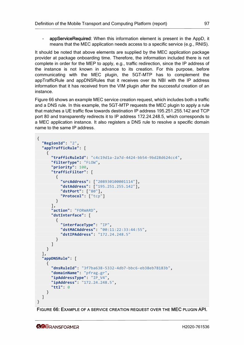
Definition of the Mobile Transport and Computing Platform (report) 97
H2020-761536
- appServiceRequired: When this information element is present in the AppD, it
means that the MEC application needs access to a specific service (e.g., RNIS).
It should be noted that above elements are supplied by the MEC application package
provider at package onboarding time. Therefore, the information included there is not
complete in order for the MEP to apply, e.g., traffic redirection, since the IP address of
the instance is not known in advance to its creation. For this purpose, before
communicating with the MEC plugin, the 5GT-MTP has to complement the
appTrafficRule and appDNSRules that it receives over its NBI with the IP address
information that it has received from the VIM plugin after the successful creation of an
instance.
Figure 66 shows an example MEC service creation request, which includes both a traffic
and a DNS rule. In this example, the 5GT-MTP requests the MEC plugin to apply a rule
that matches a UE traffic flow towards destination IP address 195.251.255.142 and TCP
port 80 and transparently redirects it to IP address 172.24.248.5, which corresponds to
a MEC application instance. It also registers a DNS rule to resolve a specific domain
name to the same IP address.
{ "RegionId": "2", "appTrafficRule": [ { "trafficRuleId": "c4c19d1a-2a7d-4424-bb54-9bd28d624cc4", "filterType": "FLOW", "priority": 100, "trafficFilter": [ { "srcAddress": ["208930100001114"], "dstAddress": ["195.251.255.142"], "dstPort": ["80"], "Protocol": ["tcp"] } ], "action": "FORWARD", "dstInterface": [ { "interfaceType": "IP", "dstMACAddress": "00:11:22:33:44:55", "dstIPAddress": "172.24.248.5" } ] } ], "appDNSRule": [ { "dnsRuleId": "3f7ba638-5332-4db7-bbc6-eb38eb78183b", "domainName": "pfrag.gr", "ipAddressType": "IP_V4", "ipAddress": "172.24.248.5", "ttl": 0 } ] }
FIGURE 66: EXAMPLE OF A SERVICE CREATION REQUEST OVER THE MEC PLUGIN API.

Definition of the Mobile Transport and Computing Platform (report) 98
H2020-761536
5.5.4 5GT-MTP monitoring interface
The 5GT-MTP monitoring interface is offered by the Monitoring Configuration Manager
(Config Manager) [11] and consumed by the 5GT-MTP in order to receive real-time
information and alerts regarding the managed infrastructure.
There are three entities whose lifecycle is controlled through this interface: exporter jobs,
alerts and dashboards. Exporter jobs are the logical representation of Monitoring data
collection jobs, and they are usually in a 1-1 relationship with the monitored entities,
although multi-entity aggregated jobs are possible. Alerts represent the logical bundle of
a communication channel between the Monitoring platform and a notification consumer,
together with the rules for notification generation at the Monitoring Platform. Finally, a
dashboard is a web page representing – in real time – several monitored timeseries in plot
format; it is a diagnostic and “active” (i.e. requiring direct user scrutiny) monitoring tool.
The exporter API allows the consumer to create, modify, delete and query exporter jobs.
Each exporter jobs contains the configuration of a polling job performed by the Monitoring
platform towards a data source, and it contains the information required to reach the
source endpoint, i.e. IP address and port, on top of the job’s configuration.
This API will usually be invoked at infrastructure deployment time, to connect the
Monitoring platform to the data plane monitoring sources such as the VIM(s), WIM(s) and
the data plane hardware.
The alert API allows the consumer to create, query, configure and delete notifications
related to breaches of thresholds imposed on the monitored data. Each alert specifies a
– potentially complex – query extracting a single value from any number of timeseries, a
label and a severity parameter to report in case of a breach to ease the parsing of the
notification at the notification consumer, the threshold value and the comparator (e.g.
greater than, lower than, greater or equal, etc.) and the target which should be notified
of the breach, in the form of a URL accepting POST requests.
This API might be called at infrastructure deployment time, to setup a baseline
notification system, or at runtime in order to more closely monitor some problematic piece
of the infrastructure, or to tighten the notification net when anticipating a heavy load or
some other external difficulty, in order to have more time to react.
Finally, the dashboard API allows the consumer to create, read, update and destroy
monitoring dashboard. After creation, a dashboard is assigned a URL the consumer can
point their browser to in order to visualize a graphical report of the status of any part of
the 5GT-MTP infrastructure.
The dashboard API requires to specify the users authorized to access the dashboard (if
access control is required), some general configuration for the plots (time plotted and
refresh frequency), and a list of panels. Each panel represents one plot window, and
allows to specify the title of the window, the query that should be plotted in the window
itself and the size of the window related to the browser window.
This API is meant to be invoked at infrastructure deployment time in order to generate
one or more dashboard for general admin infrastructure monitoring, and at runtime for
ad-hoc reporting of specific parts of the infrastructure or of some specific data for
diagnosing issues.

Definition of the Mobile Transport and Computing Platform (report) 99
H2020-761536
5.5.5 5GT-MTP placement interface
This purpose of this API is to provide a means where a myriad of PA algorithms to be
executed at the 5GT-MTP level can be triggered attaining a more granular decision (in
terms of both cloud and networking resources) with respect to the result accomplished
by the PA launched at the 5GT-SO level. Recall that in the 5GT hierarchical architecture,
the cloud and networking infrastructure details being passed from the 5GT-MTP towards
the 5GT-SO is generically abstracted. In light of this, the output of 5GT-SO’s PAs typically
describes a set of NFVI-PoPs (to host the required VNFs) and a set of LLs (enabling the
inter-NFVI-PoP connectivity). Consequently, executing the 5GT-MTP’s PA algorithm
over the output of the 5GT-SO’s PA aims at achieving a more accurate decision of both
the cloud and the networking resources that eventually will be allocated. The rationale
behind this is that the 5GT-MTP operates with a more detailed view of the all the
resources compared to the 5GT-SO.
The 5GT-MTP PA could target multiple and heterogeneous objective functions as
addressed in Section 5.3.4.1. The goal is that the 5GT-MTP relies on a common API to
request executing a particular PA algorithm. This allows more flexibility and modularity
to the 5GT-MTP architecture where conceiving a new PA algorithm can be easily
integrated into the 5GT-MTP as long as the API is used. A schematic view of the
interworking between the 5GT-MTP and a pool of potential PAs to be used is depicted in
Figure 67.
FIGURE 67: INTERWORKING BETWEEN THE 5GT-MTP AND THE PAS USING THE DEFINED
API
At the time of writing, the defined API is mostly devoted to enable that a networking-
oriented PA extends the selection of a LL previously made by the 5GT-SO PA. In other
words, the 5GT-SO provides the set of the LLs interconnecting the NFVI-PoPs to
accommodate a network service (see Section 5.5.1.1.2). For each the LL, the API allows
requesting the PA to select the inter-NFVI-PoP (i.e., WAN) resources satisfying the LL
requirements in terms of bandwidth and delay. In this regard, the API has been defined
using a REST protocol where the contents are encoded using JSON format.
The 5GT-MTP PA API supports a pair request/response messages where the 5GT-MTP
operates as a client and the PA as the server. Those messages are referred to as
interNfviPopCompRouteRequest and interNfviPopCompRouteResponse. The URI of
both messages is /compRoute. For the former message the URI is completed with the
5GT-MTP
PA#1
PA#2
PA#n
REST API
interNfviPop_CompRouteReq
interNfviPop_CompRouteRsp

Definition of the Mobile Transport and Computing Platform (report) 100
H2020-761536
selected interNfviConnectivityId which is used by both the 5GT-MTP and the selected
PA server to associate a specific compute request to its particular response.
Before detailing the contents of the above API messages, it is worth to rely on an example
where it is detailed the view and the operations to allocated inter-NFVI-PoP network
resources being made at the 5GT-MTP. Using Figure 68, let’s assume that for a network
service, the 5GT-SO selects the LL interconnecting both NFVI-PoP#1 and NFVI-PoP#3.
Once the 5GT-MTP receives the allocation message (Section 5.5.1.1.2) from the 5GT-
SO specifying that LL, the 5GT-MTP should trigger the PA to allocate the resources. The
vision of the 5GT-MTP has not only the NFVI-PoP’s Gws but also the Provider Edge (PE)
nodes attached to those NFVI-PoPs Gws as well as border nodes of all the WANs being
managed by the 5GT-MTP. Herein it is considered that internal WAN details are hidden
to the 5GT-MTP (for the abstraction purposes) and should be afterwards handled by the
specific WIM controller governing every WAN domain. Thus, the minimum topological
information used by the 5GT-MTP and usable by the PA includes the connectivity
between NFVI-PoPs’Gws and PEs (e.g., Gw#1 and PE#11, Gw·3 and PE#33) along with
the links connecting PEs between two different WAN domains (e.g., PE#12 and PE#31
in the example). For those links, specific information about the used identifiers, metric,
available bandwidth, delay, etc. are known by the 5GT-MTP.
FIGURE 68: 5GT-MTP VIEW PROVIDING INTER-NFVI-POPS CONNECTIVITY
The above considerations about the 5GT-MTP (inter-NFVI-PoP) topology information
view have been used to define the 5GT-MTP PA API. The following details the contents
of the two messages, that is the request and response operations for computing and
selecting the networking resources related to a specific LL. It is worth noting that the API
is designed to operate on per LL basis. In other words, for a network service entailing n
LLs, the PA should be triggered n times requiring n request/response message
exchanges between the 5GT-MTP and the PA.
interNFVIPopCompRouteRequest
The request message is intended to trigger the execution of a particular PA. Basically, it
carries relevant information to assist the PA execution, which is summarized in the
following set of requirements:
- Specifying the pair of source and destination endpoints, i.e., PEs attached to the
associated NFVI-PoP’s Gws to the targeted LL (in Figure 68, PE#1 and PE#3)
- Determining the PA identifier. This is used to explicitly indicate a particular PA to
be triggered. All potential PAs having their own objective functions are identified
by an individual and unique identifier.
- Description of the 5GT-MTP topology details used as input for the PA. The
topology information includes the whole 5GT-MTP vision of the all the underlying
network infrastructure: i) QoS and identifiers attributes of the connectivity
NFVI-
PoP#1
NFVI-
PoP#3
PE#11
PE#33
Gw#1
Gw#3
PE#12 PE#31WAN#1
WAN#3
LL

Definition of the Mobile Transport and Computing Platform (report) 101
H2020-761536
between WAN domains; ii) abstracted WAN encompassing specific details in
terms of nodes and links and their related identifiers and QoS parameters.
- Specifying the QoS constraints that should be guaranteed by the route
computation: minimum bandwidth and maximum latency / delay
To deal with the above requirements, the contents of the
interNFVIPopCompRouteRequest carried into the body a REST POST method are
encoded with the following JSON objects:
• paId: identifier of the PA to be executed
• srcPEId: id. of the source PE attached to ingress NFVI-PoP’s Gw of the requested
LL
• dstPEId: id. of the destination PE attached to egress NFVI-PoP’s Gw of the
requested LL
• interWanLinks: array describing the link connectivity between a pair of PEs
bordering two separated WAN domains (e.g., PE#12 - PE#31 link in Figure 67)
• aWimId: ingress WIM Id controller of the inter-WAN link
• zWimId: egress WIM id controller of the inter-WAN link
• aPEId: ingress border PE Id of the inter-WAN link
• zPEId: egress border PE Id of the inter-WAN link
• aLinkId: link id (32-bit positive integer) attached to aPEId of the inter-WAN link
• zLinkId: link id (32-bit positive integer) attached to zPEId of the inter-WAN link
• networkLinkQoS: object describing the QoS parameters associated to the inter-
WAN link
▪ linkCostValue: metric associated to the inter-WAN link
▪ linkDelayValue: delay (in ms) associated to the inter-WAN link
▪ linkAvailBwValue: available bandwidth (in Mb/s) of the inter-WAN
link
• absWanTopo: array describing for each WAN element abstracted intra-WAN
topology details
• wimId: WIM Id controller handling the WAN
• nodes: array listing all the nodes forming the abstracted WAN topology
▪ nodeId; node Identifier
• edges: array providing for each abstracted intra-WAN link/edge specific details
(i.e., identifiers and QoS parameters). Such edges provide the specific
connectivity between pairs of the intra-WAN nodes listed above
▪ aNoded: ingress node Id of the intra-WAN link
▪ zNodeId: egress node Id of the intra-WAN link
▪ aLinkId: link id attached aNodeId of the intra-WAN link
▪ zLinkId: link id attached to zNodeId of the intra-WAN link
▪ networkLinkQoS: object describing the QoS parameters
associated to the intra-WAN link
▪ linkCostValue: metric associated to the intra-WAN link
▪ linkDelayValue: delay (in ms) associated to the intra-WAN link
▪ linkAvailBwValue: available bandwidth (in Mb/s) of the intra-WAN
link
• networkLayer: specifies the switching capability supported by the intra-WAN link
• qosCons: object used for declaring the QoS constrains that the PA should deal
with

Definition of the Mobile Transport and Computing Platform (report) 102
H2020-761536
• bandwidthConsValue: specifies the demanded bandwidth to be allocated
• delayConsValue: specifies the maximum tolerated latency to be satisfied
The content of the body forming the interNFVIPopCompRouteRequest message are
shown in Figure 69 using the SWAGGER REST API editor [33].
FIGURE 69: 5GT-TMP PA API: REQUEST MESSAGE BODY FOR REQUESTING A
NETWORK COMPUTE ROUTE TO A SPECIFIC PA
interNFVIPopCompRouteResponse
If the selected PA succeeds on the computing a route between the specified endpoints
(i.e., srcPEId and dstPEId) satisfying the demanded qosCons, the PA server sends a
REST response message whose body details the explicit path (i.e., nodes and links) to
allow the 5GT-MTP then commanding the allocation operations via the related WIM
plugins of the underlying network infrastructure. Observe that the output, i.e. computed
route, may be divided into: i) intra-WAN paths segments; ii) list of inter-WAN links.
Bearing this in mind and for the sake of easing the corresponding processing at the 5GT-
MTP, the format used for presenting the computed path is passed on the basis of the
above route segmentation. Thus, the following JSON objects are included in the PA
response message:
• compRouteOutput: main object including the detailed computed route
• interNfviConnectivityId: determines the connectivity Id for a LL fir which a route
has been computed
• reqBw: specifies the bandwidth (i.e., in Mb/s) to be allocated
• interWanLinks: array with the set of inter-WAN links to be traversed by the
computed route. For each of these links
▪ aWimId: see above
▪ zWimId: see above
▪ aPEId: see above
▪ zPEId: see above
▪ aLinkId: see above
▪ zLinkId: see above

Definition of the Mobile Transport and Computing Platform (report) 103
H2020-761536
• wanPaths: array detailing for each traversed WAN, the explicit route within that
WAN
▪ wimId: see above
▪ wanPathElements: array with the ordered set of nodes and links
to be traversed on a specific WAN (controlled by the WIM Id)
• aNoded: see above
• zNodeId: see above
• aLinkId: see above
• zLinkId: l
The content of the body forming the interNFVIPopCompRouteResponse message are
shown in Figure 70 using the SWAGGER REST API editor [33].
FIGURE 70: 5GT-MTP PA API: RESPONSE MESSAGE BODY PROVIDING THE COMPUTE
PATH WHICH MAY ENCOMPASS MULTIPLE WANS
5.6 5GT-MTP workflow descriptions
In this section, the workflows for the creation and termination of the logical link and VNF
will be presented. The instantiation and termination of MEC and Radio resources, instead
is still under discussion and will be described in future deliverable (D5.5).
5.6.1 Non-nested network service instantiation
This section presents the 5GT-MTP internal workflow for instantiating an incoming non-
nested NFV-NS (network service) received from the 5GT-SO via the NBI. The flow is
composed of two steps. The first step is to allocate virtualized network resources on
logical links for the connectivity network needed for the NFV-NS as long as two or more
remote NFVI-PoPs are involved. The second step is to instantiate the VNFs on each
particular NFVI-PoP.

Definition of the Mobile Transport and Computing Platform (report) 104
H2020-761536
We consider the special case where the NFV-NS is composed a logical link connecting
two VNFs located in different VIM domains.
Extensions to different cases are straightforward.
5.6.1.1 Logical link instantiation
Figure 71 shows the 5GT-MTP internal workflow for instantiating a virtual network
resource on a logical link. The workflow is triggered by the Logical Link Allocation
Request for the NFV-NS’s connectivity network from the NFVO in the 5GT-SO to the
5GT-MTP-NFVO-RO SLPOC also referred to as the Network Functions Virtualization
Orchestrator – Resource Orchestrator (NFVO-RO). The subsequent operations of the
5GT-MTP are listed below.
1. NFVO (at 5GT-SO) sends a request to the 5GT-MTP-NFVO-RO SLPOC to
allocate network resources on a logical link using the POST method to the
resource named /abstract-network-resources within WIMNetworkResources tag
of the 5GT-SO SBI (5GT-MTP NBI). The request parameters include the identifier
of the logical link (LogicalLinkID), the identifier of the NFV-NS (ServiceID) and the
remaining network request parameters referred to as NetServParam (e.g.,
bandwidth and maximum latency). Starting from logical link (LogicalLinkID)
selected by the 5GT-SO, the RO module of the 5GT-MTP orchestrates the
connectivity across its controlled domains, i.e., transport WIMs, VIMs and radio
WIMs. The orchestration follows the basic rule described in ETSI IFA022 [29].
First the connectivity inside the WIM is created and then it is stitched with the
intra-VIM and RAN connectivity.
2. 5GT-MTP-NFVO-RO SLPOC via SBI requests from the correct transport WIM
plugin to instantiate the network connectivity inside the WAN using the method
POST to the resource named /network-resources within WIMNetworkResources
tag of the 5GT-MTP SBI.
3. WIM plugin requests from WIM controller the allocation of network resources inside the WAN for the NFV-NS’s connectivity network.
4. WIM controller instantiates the WAN network connectivity.
5. WIM controller acknowledges completion of network resource allocation to the WIM plugin. The acknowledge message includes the identifier (WanNetworkResourceID) of allocated resource as well as the ingress and egress forwarding rules for the adjacent domains (VIM and radio). In the example the forwarding rules are VPN tags. The RO inside 5GT-MTP uses the forwarding rules to configure the adjacent domains.
6. WIM plugin acknowledges completion of WAN network resource allocation to the 5GT-MTP-NFVO-RO SLPOC.
7. 5GT-MTP-NFVO-RO SLPOC requests from VIM1 plugin the instantiation of intra-
VIM network resources for the NFV-NS’s connectivity using the method POST to
the resource named /network_resources within virtualisedNetworkResources tag
(IFA005 interface) of the 5GT-MTP SBI. The request includes the identifier of the
NFV-NS (ServiceID) and ingress forwarding rule provided by the WIM.
8. VIM1 plugin forwards the instantiation request to the VIM1 controller
9. VIM1 controller creates a virtual network (VN) for connecting to the WAN.
10. VIM1 controller acknowledges completion of network resources allocation to the
VIM1 plugin. The acknowledge message includes the identifier
(Vim1NetworkResourceID) of allocated resource.

Definition of the Mobile Transport and Computing Platform (report) 105
H2020-761536
11. VIM1 plugin acknowledges completion of intra-VIM network resource allocation to the 5GT-MTP-NFVO-RO SLPOC.
12. 5GT-MTP-NFVO-RO SLPOC requests from VIM2 plugin the instantiation of intra-
VIM network resources for the NFV-NS’s connectivity using the method POST to
the resource named /network_resources within virtualisedNetworkResources tag
(IFA005 interface) of the 5GT-MTP SBI. The request carries the identifier of the
NFV-NS (ServiceID) and egress forwarding rule provided by the WIM for
connecting to the WAN.
13. VIM2 plugin forwards the instantiation request to VIM2 controller.
14. VIM2 Controller creates the virtual network (VN) for connecting to the WAN.
15. VIM2 controller acknowledges completion of network resource allocation to the
VIM2 plugin. The acknowledge message includes the identifier
(Vim2NetworkResourceID) of allocated resource.
16. VIM2 plugin acknowledges completion of network resource allocation to the radio
plugin.
17. 5GT-MTP-NFVO-RO SLPOC returns result of NFV-NS’s connectivity network
allocation back to NFVO. The acknowledge message includes the identifier
(InterNfviPoPConnectivityID) of allocated network resources.
FIGURE 71: LOGICAL LINK INSTANTIATION

Definition of the Mobile Transport and Computing Platform (report) 106
H2020-761536
5.6.1.2 VNF instantiation
Figure 71 presents the 5GT-MTP workflow for instantiating a VNF. The VNF instantiation
workflow is triggered by the Compute Allocation Request for a new VNF instance from
the NFVO to the 5GT-MTP- NFVO-RO SLPOC. The subsequent operations of the 5GT-
MTP are listed below.
1. NFVO sends a request to the 5GT-MTP- NFVO-RO SLPOC for allocation of a
VNF within an NFVI-PoP using the POST method to the resource named
/abstract-compute-resources within abstractResources tag of the 5GT-SO SBI
(5GT-MTP NBI). The request parameters include identifier of the NFV-NS
(ServiceID), the identifier (AbstractNfviPopId) of abstract NFVI-PoP where to put
the VNF and remaining compute service request parameters referred to as
ComputeServParam. If VNF is a MEC application the request contains specific
MEC service parameters referred to as MecServiceParam. 5GT-MTP uses the
ServiceID to associate compute and network request operation to the same
service. Indeed, the ServiceID is sent to VIM plugin and it allows the plugin to
associate the VNF with the VN created during logical link instantiation.
2. 5GT-MTP- NFVO-RO SLPOC via 5GT-MTP SBI requests from the VIM plugin to
instantiate the VNF using the method POST to the resource named
/compute_resources within virtualisedComputeResources tag of the 5GT-MTP
SBI.
3. VIM plugin forwards the instantiation request to the VIM controller.
4. VIM controller creates the VM and attaches it to the VN.
5. VIM controller acknowledges the completion of resource allocation back to VIM
plugin. The acknowledge message includes the identifier (ComputeResourceID)
of allocated resource.
6. VIM plugin acknowledges the completion of resource allocation back to 5GT-
MTP- NFVO-RO SLPOC.
7. If VNF is a MEC application, 5GT-MTP- NFVO-RO SLPOC via 5GT-MTP SBI
requests from the MEC plugin to create the needed MEC service rules.
8. MEC plugin forwards the request to the VIM controller.
9. VIM controller applies traffic redirection rules, activates the MEC application and
provides the required MEC services.
10. VIM controller acknowledges completion of request to the MEC plugin. The
acknowledge message includes the identifier (RequestID) of the MEC service
request.
11. MEC plugin acknowledges completion of request to 5GT-MTP- NFVO-RO
SLPOC.
12. 5GT-MTP-NFVO-RO SLPOC returns result of VNF allocation request back to
NFVO. The acknowledge message includes the identifier (ComputeResourceID)
of allocated compute resource.

Definition of the Mobile Transport and Computing Platform (report) 107
H2020-761536
FIGURE 72: VNF INSTANTIATION
5.6.2 Non-nested network service termination
This section presents the 5GT-MTP workflow for terminating a non-nested network
service. This flow is composed of two steps. The first step is to terminate the VNFs of the
NFV-NS. The second step is to delete the network resources allocated on logical links
for the connectivity network of the NFV-NS.
Similarly, to the non-nested network service instantiation workflow, we consider the
special case where the NFV-NS is composed by a logical link connecting two VNFs
located in different VIM domains.
Extensions to different cases are straightforward.
5.6.2.1 VNF Termination
Figure 73 presents the 5GT-MTP workflow for terminating a VNF. The termination
workflow is triggered by the Compute Termination Request for a VNF from the NFVO to
the 5GT-MTP-NFVO-RO SLPOC. The subsequent operations of the 5GT-MTP are listed
below.
1. NFVO sends a request to 5GT-MTP- NFVO-RO SLPOC for deletion of a VNF instance using the DELETE method to the resource named /abstract-compute-resources within abstractResources tag of the 5GT-SO SBI (5GT-MTP NBI). The request includes the identifiers (ComputeResourceID) of the VNF to be terminated.
2. 5GT-MTP-NFVO-RO SLPOC forwards the resource termination request to the appropriate VIM plugin.
3. VIM plugin forwards the resource termination request to the VIM controller. 4. VIM controller deletes the VM of the VNF instance. 5. VIM controller acknowledges the completion of resource release back to VIM
plugin. The acknowledge message includes the identifier (ComputeResourceID) of released resource.

Definition of the Mobile Transport and Computing Platform (report) 108
H2020-761536
6. VIM/WIM acknowledges the completion of resource release back to 5GT-MTP-NFVO-RO SLPOC.
7. If the VNF is a MEC application, 5GT-MTP- NFVO-RO SLPOC via 5GT-MTP SBI
requests from the MEC plugin to delete the traffic redirection rules and MEC
services of the VNF. The request includes the identifier (RequestID) of the MEC
service request to be terminated.
8. MEC plugin forwards the request to the VIM controller.
9. VIM controller deletes traffic redirection rules and MEC services of the VNF.
10. VIM controller acknowledges completion of request to the MEC plugin.
11. MEC plugin acknowledges completion of request to 5GT-MTP-NFVO-RO
SLPOC.
12. 5GT-MTP-NFVO-RO SLPOC acknowledges the completion of resources release
back to NFVO. The acknowledge message includes the identifiers
(ComputeResourceID) of released resource.
FIGURE 73: VNF TERMINATION WORKFLOW
5.6.2.2 Logical link termination
Figure 74 shows the 5GT-MTP internal workflow for terminating a virtual network
resource on a logical link. The workflow is triggered by the Logical Link Termination
Request from the NFVO in the 5GT-SO to the 5GT-MTP-NFVO-RO SLPOC. The
subsequent operations of the 5GT-MTP are listed below.
1. NFVO sends a request to the 5GT-MTP-NFVO-RO SLPOC to terminate network
resources on a logical link using the DELETE method to the resource named
/abstract-network-resources within abstractResources tag of the 5GT-SO SBI
(5GT-MTP NBI). The request parameters include the identifier of the virtualized
network resource (InterNfviPopConnectivityID) to terminate. Starting from the
knowledge of InterNfviPopConnectivityID, the RO module of MTP retrieves the
information about the virtualised network resources of its own managed domains
that need to be terminated.

Definition of the Mobile Transport and Computing Platform (report) 109
H2020-761536
2. 5GT-MTP-NFVO-RO SLPOC requests from VIM2 plugin the termination of the
virtual network (VN) used by the NFV-NS’s network connectivity. The request
includes the identifier (VIM2NetworkResourceID) of the virtualised network
resource to terminate.
3. VIM2 plugin forwards the resource termination request to VIM2 controller.
4. VIM2 controller deletes radio network resource of NFV-NS’s connectivity
network.
5. VIM2 controller acknowledges completion of release request to VIM2 plugin.
6. VIM2 plugin acknowledges completion of release request to the 5GT-MTP-
NFVO-RO SLPOC.
7. 5GT-MTP-NFVO-RO SLPOC requests from VIM1 plugin the termination of the
intra-VIM network resource of the NFV-NS’s network connectivity. The request
includes the identifier (Vim1NetworkResourceID) of the virtualised network
resource to terminate.
8. VIM1 plugin forwards the resource termination request to the VIM1 controller.
9. VIM1 controller deletes intra-VIM virtualised network resource of NFV-NS’s
connectivity network.
10. VIM1 controller acknowledges completion of release request to the VIM1 plugin
11. VIM1 plugin acknowledges completion of release request to the 5GT-MTP-
NFVO-RO SLPOC.
12. 5GT-MTP-NFVO-RO SLPOC requests from WIM plugin the termination of the
WAN virtualized network resource of the NFV-NS’s network connectivity. The
request includes the identifier (WanNetworkResourceID) of the virtualised
network resource to terminate.
13. WIM plugin forwards the resource termination request to the WIM controller
14. WIM controller deletes the WAN virtualised network resource of NFV-NS’s
connectivity network.
15. WIM controller acknowledges completion of release request to the WIM plugin.
16. WIM plugin acknowledges completion of release request to the 5GT-MTP-NFVO-
RO SLPOC.
17. 5GT-MTP-NFVO-RO SLPOC acknowledges the completion of resource release
back to NFVO.

Definition of the Mobile Transport and Computing Platform (report) 110
H2020-761536
FIGURE 74: LOGICAL LINK TERMINATION WORKFLOW