Embed Size (px)
Citation preview

General rights Copyright and moral rights for the publications made accessible in the public portal are retained by the authors and/or other copyright owners and it is a condition of accessing publications that users recognise and abide by the legal requirements associated with these rights.
• Users may download and print one copy of any publication from the public portal for the purpose of private study or research. • You may not further distribute the material or use it for any profit-making activity or commercial gain • You may freely distribute the URL identifying the publication in the public portal
If you believe that this document breaches copyright please contact us providing details, and we will remove access to the work immediately and investigate your claim.
Downloaded from orbit.dtu.dk on: Aug 18, 2018
D5.4 Guidelines for interaction between seabed and support structure
Brennan, Andrew; Sumer, B. Mutlu; Christensen, Erik Damgaard; Kirca, Özgür; Sawicki, Andrzej;Swidzinski, Waldemar; Christensen, Erik Damgaard
Publication date:2015
Document VersionPublisher's PDF, also known as Version of record
Link back to DTU Orbit
Citation (APA):Brennan, A., Sumer, B. M., Christensen, E. D., Kirca, Ö., Sawicki, A., Swidzinski, W., & Christensen, E. D.(2015). D5.4 Guidelines for interaction between seabed and support structure.

D5.4 Guidelines for interaction between seabed and support structure
Deliverable: D5.4 Guidelines for interaction between seabed and support structure
Nature of the Deliverable: Report/D5.4
Due date of the Deliverable: Month 34
Actual Submission Date: 27-02-2014
Dissemination Level: PU
Produced by: Andrew Brennan
Contributors: Andrew Brennan, B. Mutlu Sumer, Özgür Kirca, Andrzej Sawicki, Waldemar Swidzinski,
Work Package Leader Responsible:
Jan-Joost Schouten (Deltares) Andrew Brennan
Reviewed by: Erik Damgaard Christensen/B. Mutlu Sumer
Version Date Revised Pages Description of Changes
1.0 22 Sept 2014 --- 1st layout released, (AJB)
1.1 27-02-2014 --- Final
MERMAID mermaidproject.eu Seventh Framework Programme Theme [OCEAN.2011-1] “Innovative Multi-purpose off-shore platforms: planning, design and operation” Grant Agreement no.: 288710 Start date of project: 01 Jan 2012 - Duration: 48 month
MERMAID 288710 2
Table of contents 1 Executive Summary ..................................................................................................................... 3
2 Introduction .................................................................................................................................. 4
2.1 Scope of Deliverable D5.4 .................................................................................................... 4
3 Study on Seabed Characteristics .................................................................................................. 5
4 Geotechnical challenges of MUPs ............................................................................................... 6
5 Liquefaction around MUPs .......................................................................................................... 7
5.1 Liquefaction Hazard .............................................................................................................. 9
5.2 Wave-Induced Liquefaction ................................................................................................ 12
5.2.1 Residual Liquefaction .................................................................................................. 12
5.2.2 Momentary Liquefaction.............................................................................................. 16
5.3 Influence of Clay Content ................................................................................................... 17
6 Stability of Scour Protection Layers during Liquefaction Events ............................................. 18
7 Summary of Guidelines ............................................................................................................. 20
8 References .................................................................................................................................. 22

MERMAID 288710 3
1 Executive Summary
Geotechnical aspects of MUPs have been researched as part of the MERMAID project, with
particular focus on the stability of foundation soils and their necessary scour protection. Deails of
this work are published in a number of publications as provided in the reference list. Practitioners
will be particularly drawn to the book “Liquefaction around Marine Structures” which covers many
of the aforementioned subjects researched within MERMAID regarding liquefaction issues of
platform designs (Sumer, 2014). The principal guidelines emerging from the complete body of work
are:
Sandy soils have a high liquefaction potential, the effect of which must be accounted for in
foundation design.
The presence of small quantities of fines within a sandy soil can act to increase the potential for
wave-induced liquefaction. For the soils studied, this occurred for fine fractions up to 30% of
total mass. Sandy soils with larger quantities of fines, or sandy clays, were less susceptible as
the clay behaviour dominates above this fraction.
Liquefaction risk under gravity base foundations should be screened properly in the light of in-
situ and lab tests of the seabed soil. The preliminary screening methods in the literature (some
of which cited here) can be used as a first assessment. If these assessments indicate any risks,
detailed analyses and models should be applied for liquefaction assessment.
When it comes to wave-induced liquefaction, standing waves would be seen in the vicinity of
reflecting boundaries of platform foundations. Liquefaction under Standing waves, although
qualitatively similar, show features different from that caused by progressive waves. The pore
pressure accumulation and liquefaction starts at the nodal section, and progresses towards anti-
nodal section due to a diffusion mechanism. The rate of liquefaction at the nodal section seems
to be the same with the progressive wave case. Thus, mathematical models for progressive
waves would also work for standing waves as far as the nodal section is concerned.
Rock berms (protection cover) on pipelines and power transmission cables are essential to
protect the structure from floating to the seabed surface due to liquefaction, and strongly
suggested to be constructed. However, once the rock berm is constructed, care must be
exercised on backfilling the excavated soil into the trench intentionally or due to sediment
transport.
Studies showed that a cover of stones constructed around the platform foundations for scour
protection purpose would also serve for increasing the liquefaction resistance of surrounding
soil.
However, the stability of such stones against sinkage must also be assured, and studies are
ongoing to provide guidelines for this too, which should be ready before the completion of the
project (before M48).

MERMAID 288710 4
2 Introduction
This report discusses the context of deliverable D5.4 – Guidelines for Interaction between seabed
and support structure, with respect to the MERMAID project. The deliverable will discuss on the
geotechnical challenges that the MUPs could face due to the effects of waves, currents, seismic
loads, and/or a combination of them. A set of guidelines are provided which are a results of physical
model experiments carried on during the MERMAID project. The most important mechanical
processes occurring in typical foundation configurations for MUPs will be described.
2.1 Scope of Deliverable D5.4
The objective of Task 5.4 is to understand the main important geotechnical issues related to the
technical feasibility of the MUP under MERMAID. A focus is given to the phenomena of
liquefaction produced by waves and its effect on scour protections around foundations. A series of
physical model experiments and numerical modelling has been conducted by researchers as part of
the MERMAID project: B. Mutlu Sumer (DTU-MEK), Ozgur Kirca (ITU) using a wave flume
facility, Andrew Brennan (UoD) using a dynamic centrifuge equipment, and Waldemar Świdziński
& Andrzej Sawicki (IBWPAN) conducting 1-g physical modelling and a wave flume facility. A
literature review and a summary of guidelines is given through the research conducted by the
contributors, published or not.
The main objectives of this task are to support the design of the MUPs with emphasis in
liquefaction analysis. Important problems of wave-induced liquefaction are covered, such as:
residual liquefaction, momentary liquefaction, liquefaction in clay and sand mixtures, and
liquefaction in standing waves. As well, scour protections are considered relevant and have been
studied with experimental tests for wave-induced liquefaction effects over cover stones around
foundations. In the present UoD is conducting centrifuge tests (A. Brennan & D. Escribano) and
ITU (S. Kapdasli & O. Kirca) is conducting shaking table tests to study seismic induced
liquefaction effects on cover stones. The tests also include the case of seismic-induced liquefaction
on offshore foundations with no scour protection. Numerical model tests (D. Jeng, UoD) will then
be calibrated/validated in order to design charts used as an output of the project.
A 2D and 3D numerical model has also been developed through the MERMAID project by
Professor Dong-sheng Jeng (UoD). In the existing model, wave propagation around marine
infrastructures can be simulated, as well as the evaluation of the seabed response (including pore
pressure and effective stresses; liquefaction etc.) under dynamic loading. Both poro-elastic and
poro-elastoplastic soil constitution have been included in the new version. In this project, the model
will be further applied to more complicated configuration of marine infrastructures, for example,
the Seed Mussel Capture Devices in Wadden Sea. At IBW PAN a compaction/liquefaction model
has been developed, with three differential equations in the form of constitutive laws (compaction
law, stress-strain relationship and relation between compaction and pore water pressure generation)
with some material constants which have to be determined experimentally for a given soil.

MERMAID 288710 5
3 Study on Seabed Characteristics
Physical and mechanical characteristics of seabed are essential for proper designing of foundations
of platforms and other structures forming the marine infrastructure.
Typical foundation types (see D3.2 on shallow, deep and ultra-deep water foundation technologies,
and section 3, below) will be piled or gravity based for the fixed structures, and anchored moorings
for the floating structures. The loading on the foundation will be periodic and of many cycles.
Therefore the seabed characteristics of interest are the responses of these soils to cyclic loading.
Seabed characteristics at the sites showed a prevailing presence of sandy soils. In studying the
cyclic behaviour of sandy soils, the key soil characteristics will be those related to liquefaction – the
accumulation of excess pore pressures over a number of cycles, consequently reducing the effective
stress to near-zero values.
Sawicki, Kazimierowicz-Frankowska & Zabuski (2014) summarized the materials in the Krieger’s
Flak and the Wadden Sea, and identify a methodology for assessing liquefaction potential in such
soils. However, as the aim of the project is to evaluate not just the four specific cases but the
capacity for more general deployment, it was deemed prudent to identify a soil capable of
representing the behaviour of a range of sandy seabed’s rather than simply the specific soils found
at particular sites. For repeatability, and so that subsequent model tests may be carried out on the
same soils, two uniformly graded sands and one type of silt were identified as a suitable base
material. The sands were HST95, a fine, uniformly graded sand used previously in many studies as
a representative soil for offshore conditions, and another similar fine sand (ITU Sand, Table 1) that
is artificially produced/grinded and commercially available in Turkey (referred as ITU sand).
Whilst the sands were characterized in some detail by Sawicki, Mierczyński & Sławińska (2014),
the silt was used in the DTU flume tests by Sumer et al. (2012), Kirca et al. (2012, 2013, 2014) and
Kirca (2013). Some key characteristics are provided in Table 1, below, and guidance presented
within this report is largely based around the response of these soils.
Table 1. Salient soil characteristics
Soil Property Sand Type Silt Type ITU Sand HST 95 DTU Silt
D10 (mm) 0.09 0.10 0.023 D30 (mm) 0.11 0.12 0.050 D60 (mm) 0.14 0.14 0.073 Cu 1.5 1.4 3.2 Cz 1.0 1.0 1.5 Gs 2.65 2.63 2.67 γdmin (kN/m3) 12.44 14.59 11.91 γdmax (kN/m3) 15.32 17.58 16.68 emax 1.092 0.769 1.20 emin 0.699 0.467 0.57 k (m/s) in loose 1.23x10⁻⁴ 1.50x10⁻⁵ Shape Rounded Rounded Rounded
crit (o) 34.4 32 35.2

MERMAID 288710 6
Extrapolation of results to other projects should therefore only be carried out with the comparison
between soil types, and engineering judgment is recommended in determining the degree to which
another soil will replicate the behaviour observed when producing this data.
Further studies on the sensitivity of this soil to the presence of finer fractions, on the relationship
between wave loading and long term stability and on the stability of coarser soils were also carried
out for generality, and are summarized in section 4 and 5, below.
4 Geotechnical challenges of MUPs
Multi-Use Offshore Platforms (MUPs) carry out new geotechnical challenges in marine engineering
as new functions of these structures will require different foundations that will be subjected to
various loadings, including hydrodynamic and seismic loads, depending on their location (Sawicki
et al., 2014c). The foundations for MUPs may involve a wide range of configurations from fixed
steel or concrete platforms, to floating facilities. For large water depths it is necessary to study
different anchoring systems depending on the different loading regimes imposed.
Pile or jacket foundations are commonly used for fixed offshore platforms. They are designed to
resist the deadweight of the structure and environmental loads, such as cyclic loading which
imposes tensile and compressive loads to the piles, as well as lateral loading (Randolph et al.,
2005). Piles can also be used as anchors for floating foundations. Shallow foundations skirted
gravity bases and bucket foundations which are installed under self-weight, as well as caissons that
are penetrated in the seabed by suction. Similar to pile foundations, shallow foundations have to
withstand important cyclic horizontal and vertical loads that can generate excess pore water
pressures in the seabed. Floating facilities are connected to the seabed through a mooring system
connected to an anchor. Anchors are also used to provide extra stability to fixed or flexible
structures (Randolph et al., 2005).
Important aspects that have been considered particular attention for the MERMAID project are:
Flow in porous structures (scour protection, flow under GBS, flow through mussel farms and
cages)
Soil liquefaction and platform interaction
Risk of liquefaction and the sinking of cover stones and heavy structures due to liquefaction
Seismic/hydrodynamic originated cyclic loads or vibrations
Effect of clay content on processes
Support to foundations and mooring systems
Under the MERMAID project liquefaction has been broadly investigated by Sumer et al. (2010,
2012) and Sumer (2014), Kirca et al. (2012, 2013, 2014), Kirca (2013), Jeng and Zhao (2014),
Sawicki et al. (2014a, 2014b, 2014c, 2014d, 2014e, 2014f), and Sawicki & Sławińska (2014).
Other processes that need attention are those involving flow-structure-seabed interactions, such as
(Sumer, 2014b):
Turbulent boundary layer over the seabed,
Boundary layers over the surface(s) of the structure;
Boundary layer separation and lee-wake processes from and around the structure;
MERMAID 288710 7
Sediment transport and scour/erosion processes;
Various dynamic effects including wave-impact forces on structures;
Various geotechnical-engineering processes such as liquefaction.
Geotechnical site investigation is an important aspect that has to be considered, as well as a
laboratory testing program. This task involves high costs and therefore it is not always possible to
perform a detailed investigation of the soil conditions. A standard site investigation will require an
experienced geotechnical engineer who would select specific sites for in situ tests such as
boreholes, CPTs, and obtaining soil samples for laboratory testing. With these tests it is then
possible to evaluate the liquefaction potential of a site.
5 Liquefaction around MUPs
Liquefaction describes the failure of a saturated soil when high pore pressures are generated,
resulting in large strains and continuous deformation. A liquefied soil will behave as a viscous
liquid, and there the term liquefaction. Seed (1976) defined liquefaction as the condition where soil
experiences continuous deformation at a constant low residual strength or with no resistance at all,
due to build-up of pore water pressure. By the application of either static or cyclic loads pore water
pressure can build-up in the soil. This phenomenon is observed in soil deposits subjected to
undrained loading and with a loose density. The phenomenon of liquefaction will influence the
behaviour of marine structures founded on the seabed, as it may lead to instability of structures,
sinking of the liquefied seabed, floating of pipelines, massive slides, etc. (Sawicki, 2014).
Earthquake loads and strong storms are the major causes of liquefaction in marine deposits. The
main differences between wave and earthquake loading are that wave loading has a longer period,
lower frequency (0.1Hz), and the stress fluctuation is different (De Groot et al., 2006a). As well, in
the case of a storm, the loading propagates from the seabed into the subsoil and has a relatively
longer period compared with an earthquake. On the other hand, earthquake loading propagates from
the ground and moving up to the mud line.
Evidence of liquefaction in offshore structures has been reported in the literature. Christian et al.
(1974), and Herbich et al. (1984) have reported the phenomenon of floatation of pipelines due to
storms, produced by liquefaction of the seabed. Miyamoto et al. (1989) reported the subsidence of
offshore breakwaters at the Niagata Coast, Japan. Sawicki & Mierczynski (2006) and Sawicki
(2014) provide an extensive literature review regarding the practical implications of liquefaction
and the dynamics of seabed’s and marine structures. Reports on earthquake induced liquefaction in
marine structures has been well documented summarized by Sumer et al. (2007). In the 1999
Turkey Kocaeli Earthquake several cases of liquefaction were observed in marine structures such
as: behind quay wall and sheet-piled structures, settlement, tilting, and even collapse of structures
near the shoreline, slope failures, and lateral spreading.
Gravity based foundations, such as the type of caisson breakwater (Figure 1), may encounter
liquefaction produced by standing waves (see section 4.2.1), and under the structure. Under the
caisson, pore water pressure can build up by wave motion and by caisson motion (Kudella et al.,
2006) or a gravity based foundation (Rahman et al., 1977). Under extreme conditions, the buildup
of pore pressure will lead to liquefaction. Then, the areas of potential pore water pressure build up

MERMAID 288710 8
on a caisson type of foundation will be: the area in front of the breakwater centered at the nodal
sections and extending towards the anti-nodal sections (zone 1, Figure 1), and the area under the
breakwater centered at the middle of the width and extending towards the onshore and offshore
ends of the foundation (zone 2, Figure 1). Puzrin et al. (2010) investigated such a case where
several caissons near Barcelona harbor had sunk into seabed due to storm waves.
The pore water pressure build-up due to the movement of a gravity based foundation can be
produced by an overturning moment over a breakwater, which produces a kind of “rocking motion”.
However, in order to reach liquefaction by the rocking motion large wave impacts have to be
applied in order to generate significant overturning moment over the structure. Sumer et al. (2008)
observed that pore water pressure build up due to rocking motion over a caisson was strongly
dependent on the amplitude of the caisson motion. De Groot et al. (2006a) reported field
observations of pore water pressure build up on the Ekofisk oil storage tank in the North Sea after a
storm, although the pore pressure build up was not sufficient to cause liquefaction. Other case
histories where liquefaction took place in marine structures have been reported by Zen et al. (1986),
and Chaney & Fang (1991).
Figure 1. Caisson breakwater and potential liquefaction zones (Modified from Sumer, 2014)
A commonly used foundation for marine structures, and especially for offshore wind turbines are
the monopiles, which are feasible to install for water depth up to 30 m. The high cyclic lateral
moments applied to these structures, due to wind and wave loading, are transferred to the soil
through lateral resistance of the embedment (Cuellar, 2011). Strong cyclic loads produced by a
storm or an earthquake, may generate a buildup of pore water pressure which can affect the pile’s
capacity and stability. After this event, small cyclic lateral loads will allow the excess pore water
pressures to dissipate and therefore the soil surrounding the monopile will densify.
The process of pore pressure buildup and subsequent liquefaction can also affect the stability of
stone protections used in marine structures, such as scour protections (Sekiguchi et al., 2000; Sumer
et al., 2010), and rock berms. The experiments of Sekiguchi et al. (2000) and Sumer et al. (2010)
showed that cover stones such as the ones used for scour protections sink when the seabed liquefies.
Yet, having a cover of stones above the liquefiable layer increases the liquefaction resistance as the

MERMAID 288710 9
stones densify the soil. Rock berms are installed over a pipeline or a power transmission line/cable
to protect them from floating. After installing the rock berm the trench may be backfilled with in
situ sediment intentionally or by sediment transport. Due to this backfilling process this sediment
will be in a loose state and therefore prone to liquefaction. If liquefaction takes place the rock berms
will be subjected to the motion of the liquefied soil. As well, if rock berms are installed on a
pipeline lying on a loose sediment, and therefore prone to liquefaction due to wave action, the berm
structure will also be exposed to motions of the liquefied soil (Sumer, 2014).
Recently, Kirca (2013) studied the sinking of an individual cover/armor stone (i.e. irregular shaped
heavy object) due to wave-induced liquefaction. Results indicated that the shape of the block is of
minor (or no) importance from the dynamics of sinking standpoint. Based on their experimental
data and the earlier studies, Kirca (2013) suggested a tentative procedure to assess the sinking
damage (ultimate sinking depth) of an object on the seabed in the case of residual liquefaction. A
broader discussion of the subject is given Sumer (2014) with assessment examples of sinking for
different individual heavy objects.
The following sections will describe the procedures for the assessment of liquefaction potential, the
mechanism of wave-induced liquefaction, and the effect of clay content on liquefaction
susceptibility.
5.1 Liquefaction Hazard
Seabeds are susceptible to liquefaction and macroscopic degradation of their mechanical properties,
which in turn is dangerous for offshore structures because of potential excessive settlements,
sinking, or the loss of stability. Therefore, it is important for proper designing of marine
infrastructure to recognize the liquefaction susceptibility of seabed in relation with interactions with
structures and water.
Different approaches have been developed in order to evaluate liquefaction hazard of granular soils
(Seed & Idriss, 1971; Ishihara, 1977; Dobry et al., 1982; Iwasaki et al., 1984). In the previous
references the liquefaction potential is analyzed in terms of the soil properties. The soils that are
more susceptible to liquefaction are saturated sands and silts. In terms of density, a loose deposit
will experience strain softening due to a monotonic or cyclic load, when the shear stresses applied
are larger than the ultimate shear strength of the soil. For this condition the loose soil experiences
flow liquefaction, deforming at a low constant residual stress. For a dense deposit, the soil
experiences strain hardening due to cyclic undrained loading. In this case cyclic mobility may take
place as the dense soil generates negative excess pore water pressures.
The properties that make a granular soil more or less susceptible to liquefaction are the density,
confining stress, soil structure (fabric, age, and cementation), the magnitude of the cyclic loading,
and the extent of stress reversals.
Seed & Idriss (1971) developed a simplified procedure for the evaluation of the liquefaction
resistance of soils due to earthquake loading. A state of the art report used as a standard for
liquefaction hazard assessment was done by Whitman (1985, NRC). Later on, Youd & Idriss (1997)
updated the simplified procedure.

MERMAID 288710 10
The simplified procedure for liquefaction hazard assessment is based on empirical evaluations of
field observations and laboratory tests. Two parameters are needed for the evaluation: the seismic
demand on a soil layer (CSR: critical stress ratio), and the capacity of the soil to resist liquefaction
(CRR: cyclic resistant ratio). The evaluation of the CSR is done by expression 1 (Seed & Idriss,
1971), where amax is the peak horizontal acceleration at the ground surface, g the acceleration of
gravity, σvo and σ’vo are the total and effective vertical overburden stresses, respectively, and rd is
the stress reduction coefficient which account for the flexibility of the soil profile. The
modifications done to the original expression of Seed & Idriss (1971) were by changing the values
of rd.
max0.65( / )( / ' )vo vo dCSR a g r (5.1)
For the evaluation of the liquefaction resistance a correlations are done based on field test results
such as the cone penetration test (CPT), the standard penetration test (SPT), the Becker penetration
test (BPT), and shear wave velocity measurements. To obtain the CRR in terms of field tests a
series of charts have been developed to correlate the test characteristic parameters to the CRR
(Youd & Idriss, 2001; Idriss & Boulanger, 2010).
The triggering of liquefaction is then analyzed by comparing the CSR and CRR, and obtaining a
factor of safety FS = CRR/CSR. For the evaluation of liquefaction potential produced by wave
loading a similar method than the previous one can be employed. Similar than the shear stresses
applied by an earthquake wave loading will produce a gradual pore water pressure build up in the
soil which may lead to liquefaction (Sumer, 2014). Peacock & Seed (1968) and Alba et al. (1976)
performed a series of cyclic simple shear tests to study pore water pressure build up in sand. The
previous authors obtained an empirical expression relating the shear stresses applied and the mean
effective stress of the soil with the number of cycles Nl to reach liquefaction. The value of Nl will
mainly depend on the amplitude of the oscillating shear stress acting on the soil τ, the mean
effective stress σ’o, and density of the soil. Sumer (2014) developed a method to describe the
buildup of pore water pressure due to wave loading based on the previous authors. Expression 2
calculates the number of loading cycles required to cause liquefaction Nl , where the ratio τ/σ’o is
the normalized shear stress (shear stress / mean effective stress), and α and β are empirical
coefficients. In this case, the soil is considered completely undrained. Sumer et al. (2012) gives an
empirical expression for the coefficients α and β in terms of relative density. Recently, Jeng and
Zhaou (2014) have modified this approach with a time dependent shear stress term. Their solution
was seen to be close to that of Sumer et al. (2012).
By using Biot equations Sumer (2014) (earlier Sumer and Fredsoe, 2002) developed a mathematical
analysis to obtain the stresses in the soil as well as the pore water pressures under a progressive
wave (for a detailed analysis of these expression refer to Sumer, 2014). In this way, the generated
excess pore water pressure can be compared with the mean effective stress of the soil to see whether
under the wave loading and soil conditions liquefaction is possible.
Another way to estimate liquefaction potential due to wave loading is to correlate the relative
density of the soil with SPT or CPT results. In this way the resistance of soil to liquefaction can be
calculated similar to the CRR of the simplified procedure (Seed & Idriss, 1971; Youd & Idriss,
2001).

MERMAID 288710 11
There is scarce literature regarding the liquefaction potential assessment of the soil interacting with
a structure. Based on case histories of caisson foundations, de Groot et al. (2006b) developed a
chart where four different types of liquefaction failures are induced by wave loading. The diagram
in Figure 2 is in terms of the relative density Dr, and the ratio of the characteristic drainage time
TCHAR,DRAIN and the wave period T, where the characteristic drainage time is defined as expression
(5.2).
2
,CHAR DRAIN
v
dT
c
(5.2)
Where:
d: Thickness of the subsoil layer, measured from the seabed to the impermeable base,
cv: coefficient of consolidation.
Figure 2 Potential failure types as a function of relative density and relative characteristic
drainage period (replicated from de Groot et al., 2006b).
The ratio of the characteristic drainage time and the wave period can be understood as the time
required for the water to drain out of the soil as a results of the wave loading. Therefore, as this ratio
becomes larger, the soil is more susceptible to residual liquefaction.
The four types of failure mechanisms of a caisson foundation due to the action of wave loading are
defined in the following (de Groot et al., 2006; Sumer, 2014):
I Liquefaction flow failure: Due to one or a few extreme wave loads large continuous
deformations are generated in the foundation, as a results of a reduction in soil strength
caused by accumulated pore pressures.
II Stepwise liquefaction failure: Significant residual accumulated pore pressures cause
failure through stepwise residual caisson displacements.

MERMAID 288710 12
III Stepwise failure: Failure through stepwise caisson displacements without significant
residual accumulated pore pressures. This type of failure may be related to the failure
mechanism produced by momentary liquefaction.
IV Wobble failure: Large cyclic shear strains produce failure by very large phase-resolved
deformations.
The diagram developed by de Groot et al. (2006b), and shown in Figure 2, can be used as a
preliminary assessment of liquefaction potential under a caisson or gravity based structure. At the
same time, Sumer (2014) developed an approximate mathematical model which can be adopted to
verify liquefaction potential. Refer to Sumer (2014) for detailed description of the model.
5.2 Wave-Induced Liquefaction
Marine soils are constantly exposed to wave action. The liquefaction phenomenon is essentially
associated with large waves. These waves may have a period of 5–15 s, with 50 or 100 year-return-
period wave heights as much as 1-2 m or larger in coastal areas, and 10–20 m in offshore areas.
Marine soils that can be subjected to liquefaction are basically fine sands and silts, or a mixture
such as silty sand or clayey sand (Sumer, 2014).
Liquefaction is generated mainly by two different mechanisms in waves (Sumer & Fredsoe, 2002;
Sumer, 2014): a buildup of pore pressure (residual liquefaction), and an upward-directed vertical
pressure gradient in the soil during the passage of a wave trough (momentary liquefaction). Several
experimental studies have observed the phenomenon of wave-induced liquefaction, such as: Tzang
(1998), Teh et al. (2003, 2006), and Sumer et al. (1999, 2006, 2012, 2014). The observations of
wave flume tests performed by Sumer et al. (1999, 2012) have identified three primary factors that
affect the accumulation of pore water pressures in the soil: the cyclic shear stress ratio (ratio of
shear stress and mean effective stress), the period of cyclic loading, and the number of loading
cycles required to reach liquefaction. Wave flume tests were also performed by Sawicki et al.
(2014xx) to provide empirical data for testing different models of the seabed. A theoretical analysis
of the models was done by considering classical soil mechanics, including the Biot type approach.
Different theoretical descriptions have also been attempted by different authors such as: Been &
Jefferies (1985), Ishihara (1985), Lade & Yamamuro (1997), or Sawicki & Mierczynski (2006).
The following sections include a more general description of residual and momentary liquefaction
produced by wave loading.
5.2.1 Residual Liquefaction
When a loose granular soil in undrained conditions is subjected to a progressive wave the pore
pressure will gradually build-up, leading to liquefaction as the excess pore water pressure reaches a
critical value. Residual liquefaction is a progressive process, occurring first at the surface of the
seabed and then progressing downwards. After liquefaction the soil starts to compact, starting from
the base of the liquefiable layer and progressing upwards. Figure 1 shows the mechanism of a
progressive wave and its effect on the seabed soil. The seabed soil will be subjected to a variation of
pressures due to the progressive wave (Figure 1b), as the pressures are different under the wave
crest and the wave trough. An element of soil (Figure 1c) will then experience shear stresses,

MERMAID 288710 13
varying periodically with time as the wave loads pass. If the seabed soil is loose and at undrained
conditions it is possible that pore water pressures starts to build up.
Experimental investigations studying the residual liquefaction process in a granular soil has been
reported by Sekiguchi et al. (2000) and Miyamoto et al. (2004) on centrifuge tests, and Sumer et al.
(2004, 2006), and Kirca et al. (2013) on wave flume tests. The study of wave-induced liquefaction
or build-up of pore pressure in silt has been reported by Clukey et al. (1983, 1985), Foda & Tzang
(1994), Tzang et al. (1992), Tzang (1998), and Sumer et al. (1999), all previous studies undertaken
in a laboratory wave flume. Similar experimental studies for cohesive soils have been reported by
Wit & Kranenburg (1992), and Kessel & Kranenburg (1998).
Figure 3 Elastic deformation of the seabed soil under a progressive wave (Sumer, 2014): (a)
Element of soil and initial conditions without wave loading, (b) Periodic pressure variation of the
soil under a progressive wave, (c) Generation of shear stresses in the soil.
Standing waves can also produce residual liquefaction, affecting breakwaters, seawalls, and large
caisson structures. These waves are formed by the combination of the reflected waves meeting the
incoming waves (Dean & Dalrymple, 1984). Standing waves and liquefaction has been studied by
Sekiguchi et al. (1995), Sassa & Sekiguchi (1999, 2001), and Kirca et al. (2012, 2013). Figure 2

MERMAID 288710 14
shows the configuration of Kirca et al. (2013) tests performed on a wave flume (Figure 2a), and
Figure 2(b) shows the distribution of shear strains in the soil due to standing waves. The shear
strains are larger under the node (N in Figure 2b) and decrease as one approaches the antinodes (A
in Figure 2b). For the configuration of the tests, a plate was used as to produce the reflected waves
(Figure 2a).
The process of pore water pressure build up at the node was described by Kirca et al. (2013) as a
rearrangement of the soil grains due to cyclic shear strains, and at the same time the pore water is
pressurized leading to a build-up. The accumulated pore water pressure results in liquefaction of the
seabed and then spreads towards the antinode section. Similarities between the mechanism of
standing waves and progressive waves were observed in the previous tests.
(a) (b)
Figure 4 Experimental setup of Kirca et al. (2013) wave flume tests: (a) Points 1-6 are the
location of pore water pressure measurements, (b) Variation of shear stresses and strain in the soil
as a function of horizontal distance (Kirca et al., 2013).
The main findings of residual liquefaction processes in marine soils are:
Centrifuge tests performed by Sekiguchi et al. (2000) found that liquefaction progressed
downwards when applying severe wave loading. As well, protecting the surface of the
liquefiable layer with gravel suppressed liquefaction taking place. The later finding was
confirmed by Sumer et al. (2010) on wave flume tests.
The sequence of residual liquefaction was studied by Sumer et al. (2004, 2006) with tests
performed on a standard wave flume. The excess pore pressure accumulated with the wave
action until it reached a critical level, and the soil liquefied. The tests also showed how
liquefaction was first developed at the mudline and progressed downwards. These results were
in accordance with those from Sassa & Sekiguchi (1999), and Miyamoto et al. (2004). Sumer et
al. (2006) also observed that the entire layer of soil was liquefied down to the impermeable
base. Teh et al. (2003) and Sumer et al. (2011) observed that when the depth of the loose layer is

MERMAID 288710 15
large enough the soil only liquefies to an intermediate depth. Figure 3 shows the sequence of
residual liquefaction under a progressive wave at a certain depth, considering the following
stages of the process: pressure build up, liquefaction, compaction of the liquefied layer,
dissipation of excess pore pressures, and the formation of ripples at the seabed soil.
Miyamoto et al. (2004) and Sumer et al. (2006) studied the process of densification
(solidification, compaction) of the liquefied layer, the first authors using a small wave tank in a
centrifuge, and the latest authors using a wave flume. The densification process progresses
upwards during continued wave loading, and as a result of the densification the mudline will
continuously move downwards (Sumer, 2014). The total time at which the excess pore pressure
has completely dissipated will coincide with the time at which the compaction front arrives at
the mudline (Sumer, 2014). At this condition, no further settlement is experienced by the soil.
Sumer et al. (2006) observed that as the wave height increases so does the shaking of the
liquefiable soil, and therefore the densification is larger. The relative density of the soil changed
from a loose condition to dense after the liquefaction/compaction sequence of the tests.
Sumer et al. (2006) observed that after the compaction stage, waves produced ripples in the soil
surface (Figure 4) which reached a certain height and then stayed constant. These ripples were
similar in steepness for a sediment without previous liquefaction.
Sumer (2014) compared Sassa & Sekiguchi’s (1999) wave centrifuge tests with those from
Sumer et al. (2006) wave flume test results. By considering non-dimensional parameters the
average pore pressure of the soil at a certain depth on the wave flume tests was compared by the
centrifuge field” experiments, giving very similar results, and therefore proving that wave flume
tests can be used as a physical model test for studying buildup of pore pressure and liquefaction
analysis, provided that the results are analyzed and interpreted on the basis of non-dimensional
parameters (Sumer, 2014).
Liquefaction under Standing waves was studied by Sassa & Sekiguchi (1999) on centrifuge
tests, and Kirca et al. (2013) on wave flume tests. Both references observed liquefaction
phenomena occurring at the nodal section and spreading to the antinodal section. It was found
that the number of waves to cause liquefaction at the nodal section was the same from that
experienced by progressive waves for the same wave height (Kirca et a., 2013).
Sekiguchi et al. (1995) derived a closed-form solution considering 1D poroelastoplasticity under
Standing waves, and Sassa & Sekiguchi (2001) presented a 2D constitutive model in a finite
element analysis, comparing their numerical results with their centrifuge tests (Sassa &
Sekiguchi, 1999).

MERMAID 288710 16
Figure 5. Time series of period-averaged excess pore water pressure at depth z. Schematic
description (Sumer et al. 2006).
Figure 6. Bed ripples: (a) plan view, (b) side view. (Sumer et al. 2006).
5.2.2 Momentary Liquefaction
This type of liquefaction occurs over a short period of time during the passage of a wave trough.
Under the wave trough the excess pore water pressure will be negative and therefore induce a lift
force on the seabed (Figure 5). If the lifting force exceeds the submerged weight of the soil, this will
fail the soil, and as a result it will liquefy.
Figure 7. Pore water pressure distribution (in excess of hydrostatic pressure during the passage of
a wave trough. (a) Saturated soil. (b) Unsaturated soil (Sumer, 2014).
Sumer (2014) (earlier Sumer and Fredsoe, 2002) performed an analytical solution to evaluate
momentary liquefaction on a saturated soil. It was found that momentary liquefaction will not occur

MERMAID 288710 17
in a completely saturated soil. Similar conclusions were given by Hsu & Jeng (1994). For the case
of an unsaturated soil containing air/gas, the vertical pressure gradient can be very large,
particularly at small depths, and therefore the lifting generated at the soil surface can be significant
(Sumer, 2014). Studies on unsaturated soil and momentary liquefaction have been undertaken by
Sakai et al. (1992a) limited to shallow waters, and Sumer (2014) with an analytical analysis.
For the occurrence of momentary liquefaction it seems that an unsaturated soil is essential.
Evidence of air and gas bubbles in marine soils has been registered by Hattori et al. (1992), Sakai et
al. (1992), Mory et al. (2007), and Torum (2007). Zen & Yamazaki (1990a) performed an
experimental study of momentary liquefaction and densification of the seabed. The results of the
previous authors indicated that by pressurizing the water in a cyclic manner momentary liquefaction
occurred at the seabed. As well, very large settlements and densification were measured resulting
from the sequence of liquefaction and compaction.
5.3 Influence of Clay Content
The seabed may contain cohesive soils or a composite material, such as clayey silt or clayey sand
(Kirca et al., 2014). Kirca et al. 2014 conducted wave flume tests in order to study the influence of
clay content on wave-induced liquefaction. Two mixtures were considered: mainly silt-clay, and
some complementary tests with sand-clay. The experiments by Kirca et al. (2014) showed that clay
content has a significant influence on wave-induced liquefaction of sand and silt. It was observed
that up to a clay content of roughly 30% the liquefaction susceptibility of silt was increased. For
clay contents higher than 30% the silt-clay mixture was not liquefied. For the sand-clay mixture
there was dependence on the size of sand grains: for a sand with D50 = 0.4 mm. the mixture was
liquefied by adding 10.8% of clay, whereas for a sand with D50 = 0.17 mm. the mixture was
partially liquefied by adding only 2.9% of clay. The authors linked the previous results with soil
permeability and its influence on the buildup of pore water pressure. For the case of the silt-clay
mixture with a clay content less than 30%, Kirca et al. (2014) explains that the soil had a low
plasticity behaviour as referred by Gratchev et al. (2006), allowing the soil grains to rearrange under
the cyclic shear strains, and therefore leading to a build-up of water pore pressure. By increasing
further the clay content (> 30%) the permeability of the mixture decreases significantly and the soil
grains are not able to rearrange, and the mixture behaves as a high plasticity soil, with a higher
resistance to liquefaction. The results obtained by Kirca et al. (2014) show that they are dependent
on the type of clay used, and therefore the clay content limit of 30% for the silt-clay mixture should
not be taken as a constant threshold value (Sumer, 2014).
The practical applications of the previous study is that by following standard liquefaction potential
analysis methods, the soil’s permeability has to be assessed as liquefaction susceptibility is directly
linked to this parameter (Kirca et al., 2014).
Sawicki et al. (2014) performed an experimental investigation to study the effects of fines in sand
on liquefaction susceptibility, albeit not under wave loading. Their findings suggest that fines do
not essentially influence the liquefaction susceptibility of sand.
Other studies have concentrated in purely clay sediments, with laboratory results suggesting that
waves can liquefy these sediments, producing high density mud layers (Linderberg et al., 1989; de
Wit & Kranenburg, 1992; de Wit, 1995).

MERMAID 288710 18
6 Stability of Scour Protection Layers during Liquefaction Events
The phenomenon of scour around offshore foundations may occur due to the effect of currents, the
combined effect of waves and currents, and due to seismic action. To reduce the effect of scour
around offshore foundations a certain type of protection is needed. The most common type of scour
protection used for offshore foundations consist of an armour layer of stones. Many site
investigations indicate that numerous structural failures can be attributed to the effects of wave-
induced liquefaction of the seabed, which will affect the scour protection. Previous studies on the
effect of liquefaction over scour protections of stones has been focused on the wave-induced
liquefaction (Sumer et al. 2010; Sekiguchi et al. 2000).
Sekiguchi et al. (2000) studied a fine silt covered partially and completely with gravel. The tests
were performed on a small wave tank installed on a centrifuge. During the tests a steady seepage
flow was maintained. When the sand was fully covered by a layer of gravel it did not liquefy.
Sekiguchi et al’s tests demonstrated that a cover of stones could prevent liquefaction induced by
waves on a loose bed of fine sand.
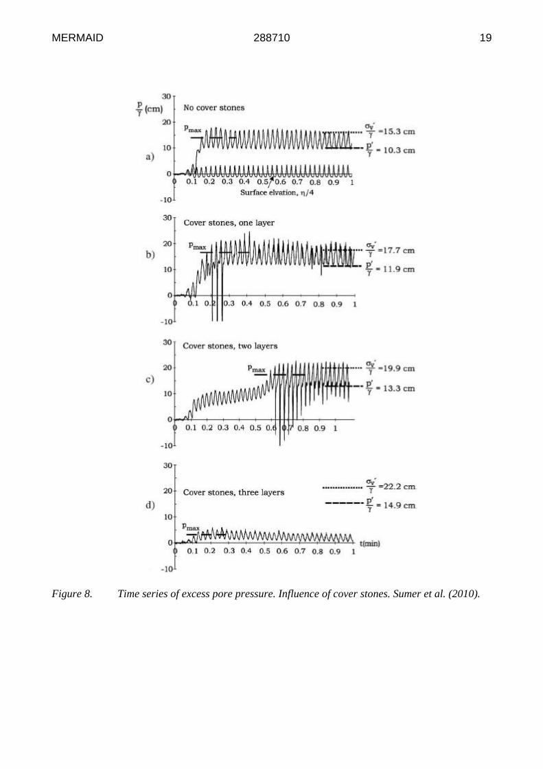
Sumer et al. (2010) did similar experiments on a wave flume, using silt and a cover of stones.
Figure 6 shows the time series of pore water pressure at a depth of 16 cm for four different tests. In
the first case (Figure 6a), the liquefiable soil has no cover of stones and the pore pressure gradually
builds up until liquefaction occurs. A similar result was obtained when using one and two layers of
cover stones (case b and c in Figure 6). These results were also confirmed for depths at 5, 10 and 13
cm. In the last case (Figure 6d) where three layers of cover stones were used, liquefaction did not
occur. The previous results were concluded to be a cause of densification of the soil with the cover
of stones, and as the cover layer thickness increased so did the density of the soil. Figure 7 plots the
results of Figure 6, in terms of the number of waves to reach liquefaction (liquefaction resistance)
against the relative density of the soil. It is observed that even though cases (b) and (c) in Figure
also liquefied, the number of waves to reach liquefaction was increased compared to cover layers,
case (a) Figure 6.
No references were found regarding the effect of seismic-induced liquefaction on scour protections.
Currently, the University of Dundee centrifuge laboratory, as part of the MERMAID project are
undertaking an experimental study of liquefaction produced by earthquakes and its effect on cover
stones. The tests consist of a layer of fine loose sand, covered by a layers of stones. The number of
layers or surcharge applied to the soil will be modified. The model is tested at 50g level and fully
saturated. As well, a similar test program is underway at ITU on a shaking table equipment for
comparison purposes. Again fine loose sand (see Table 1) in a fully saturated state is used for these
tests. For start, the exerted shaking is on a single horizontal axis, sinusoidal with a peak acceleration
of 0.5g. In the following stages, additional degrees of freedom will be added to the shaking
(horizontal+horizontal or horizontal+vertical). The test results will then be compared with the ones
performed by Sekiguchi et al. (2000) and Sumer et al. (2010).
MERMAID 288710 19
Figure 8. Time series of excess pore pressure. Influence of cover stones. Sumer et al. (2010).

MERMAID 288710 20
Figure 9. Liquefaction resistance as a function of the soils relative density. The first data point on
the left: no cover stones. Middle data point: one layer of stones. Third data point: two cover layers.
Arrow sign of “No Liq.”: three cover layers (Sumer et al., 2010).
7 Summary of Guidelines
Based on the work carried out under the auspices of MERMAID, the following guidance is
provided:
Sandy soils have a high liquefaction potential, the effect of which must be accounted for in
foundation design.
The presence of small quantities of fines within a sandy soil can act to increase the potential for
wave-induced liquefaction. For the soils studied, this occurred for fine fractions up to 30% of
total mass. Sandy soils with larger quantities of fines, or sandy clays, were less susceptible as
the clay behaviour dominates above this fraction.
Liquefaction risk under gravity base foundations should be screened properly in the light of in-
situ and lab tests of the seabed soil. The preliminary screening methods in the literature (some
of which cited here) can be used as a first assessment. If these assessments indicate any risks,
detailed analyses and models should be applied for liquefaction assessment.
When it comes to wave-induced liquefaction, standing waves would be seen in the vicinity of
reflecting boundaries of platform foundations. Liquefaction under Standing waves, although
qualitatively similar, show features different from that caused by progressive waves. The pore
pressure accumulation and liquefaction starts at the nodal section, and progresses towards anti-
nodal section due to a diffusion mechanism. The rate of liquefaction at the nodal section seems
to be the same with the progressive wave case. Thus, mathematical models for progressive
waves would also work for standing waves as far as the nodal section is concerned.
Rock berms (protection cover) on pipelines and power transmission cables are essential to
protect the structure from floating to the seabed surface due to liquefaction, and strongly
suggested to be constructed. However, once the rock berm is constructed, care must be

MERMAID 288710 21
exercised on backfilling the excavated soil into the trench intentionally or due to sediment
transport. Such a loose backfill will be prone to liquefaction, and if liquefaction takes place, the
motion of the liquefied soil may presumably damage the rock berm more severely than the wave
motion on the bare berm itself.
Studies showed that a cover of stones constructed around the platform foundations for scour
protection purpose would also serve for increasing the liquefaction resistance of surrounding
soil. Once the stone cover is designed with respect to hydraulic loads and filtering requirements,
an additional check is suggested to be performed to assess the effect of the stone cover on
increasing the resistance to wave-induced liquefaction, so that a fine-tuning can be performed
on the dimensions or layer thickness of the stone cover if deemed necessary.
The influence of earthquake shaking and seismic-induced liquefaction on scour protection of
platforms has not yet been particularly studied in the available literature. But, there are
significant studies underway in the scope of MERMAID project the results of which are
expected to shed light on this problem, once published.
A state-of-the-art of “Liquefaction around Marine Structures” can be found in the book with the
same title, which covers many of the aforementioned subjects researched under MERMAID project
and additional matters regarding liquefaction issues of platform designs (Sumer, 2014). The book
itself serves as a compendium of guidelines and will be useful for designers and practitioners from
this aspect.

MERMAID 288710 22
8 References
The publications produced under the scope of (partially supported by) MERMAID are underlined
(for a complete list, visit http://www.mermaidproject.eu/dissemination/outreach).
Alba, P.D., Seed, H.B. and Chan, C.K. (1976). Sand liquefaction in large-scale simple shear tests.
Journal of Geotechnical Engineering Division, ASCE, vol. 102, No. GT9, 909-927.
Been, K. & Jefferies, M.G. (1985). A State Parameter for sands. Géotechnique, Vol. 35, Issue 2, 99-
112.
Chaney, R.C. and Fang, H.Y. (1991). Liquefaction in the coastal environment: An analysis of case
histories. Marine Geotechnology, vol. 10, No. 3-4, 343-370.
Christian, J.T., Taylor, P.K., Yen, J.K.C. and Erali, D.R. (1974). Large diameter underwater
pipeline for nuclear plant designed against soil liquefaction. Offshore Technology Conference,
May 6-8, 1974, Houston, TX, OTC 2094, 597-606.
Clukey, E.C., Kulhawy, F.H. and Liu, P.L.F. (1983). Laboratory and Field investigation of sediment
interaction. Cornell University, Itacha, New York, Geotechnical Engineering Report 83-9, and
Joseph H. DeFrees Hydraulics Laboratory Report 83-1.
Clukey, E.C., Kulhawy, F.H. and Liu, P.L.F. (1985). Response of silts to wave loads: Experimental
study. In: Strength Testing of marine sediments, Laboratory and In-Situ Measurements, ASTM
stp 883, R.C. Chaney and K.R. Demars, Eds, Philadelphia, 381-396.
Cuellar, P. (2011). Pile Foundations for Offshore Wind Turbines: numerical and experimental
investigations on the behavior under short-term and long-term cyclic loading. Ph.D. thesis,
University of Technology, Berlin, Germany.
Dean, R.G. & Dalrymple, R.A.(1984). Water Wave Mechanics for Engineers and Scientists,
Prentice-Hall, Inc., New Jersey.
De Groot, M. B., M. D. Bolton, P. Foray, P. Meijers, A. C. Palmer, R. Sandven, A. Sawicki, and T.
C. Teh. (2006a). Physics of liquefaction phenomena around marine structures, J. Waterw. Port
Coastal Ocean Eng., 132(4), 227–243.
De Groot, M.B., Kudella, M., Meijers, P. and Oumeraci, H. (2006b). Liquefaction Phenomena
underneath Marine Gravity Structures Subjected to Wave Loads. Journal of Waterway, Port,
Coastal and Ocean Engineering, ASCE, vol. 132, No 4, 325-335.
De Wit, P.J. & Kranenburg, C. (1992). Liquefaction and Erosion of china clay due to waves and
current. International Conference on Coastal Engineering: ICCE 1992, Venice, Italy.
De Wit, P.J. (1995). Liquefaction of cohesive sediments caused by waves. Communications on
Hydraulic Engineering, Report No. 95-2, Doctoral thesis, Delft University of Technology,
Faculty of Civil Eng. The Netherlands.
MERMAID 288710 23
Dobry, R., Ladd, R.S., Yokel, F.Y., Chung, R.M., and Powell, D. (1982). “Prediction of Pore Water
Pressure Buildup and Liquefaction of Sands during Earthquakes by the Cyclic Strain Method,”
NBS Build. Sci. Ser. 138, National Bureau of Standards, Gaithersburg, Maryland.
Foda, M.A. & Tzang, S.Y. (1994). Resonant fluidization of silty soil by water waves. Journal of
Geophysical Research, vol. 99, No. C10, 20, 463-20, 475.
Herbich, J.B., Schiller, R.E., Dunlap, W.A. and Watanabe, R.K. (1984). Seafloor Scour, Design
Guidelines for Ocean-Founded Structures, Marcel Dekker, INC., New York and Basel.
Idriss, I.M. & Boulanger, R.W. (2010). SPT-Based Liquefaction Triggering Procedures. Center of
Geotechnical Modelling, Report No UCD/CGM-10/02, University of California at Davis.
Hsu, J.R.S & Jeng, D.S. (1994). Wave-induced soil response in an unsaturated anisotropic seabed of
finite thickness. International Journal for Numerical and Analytical Methods, in Geomechanics,
vol. 18, No. 11, 785-807.
Ishihara, K. (1977). Simple Method of Analysis for Liquefaction of Sand Deposits during
Earthquakes. Soils and Foundations, Vol. 17, No. 3, pp. 1-17.
Ishihara, K. (1985). Stability of Natural Deposits during Earthquakes. Proceedings, 11th
International Conference on Soil Mechanics and Foundation Engineering, San Francisco, vol. 1,
321-376.
Iwasaki, T., Tokida, K. and Arakawa, T. (1984). Simplified procedures for assessing soil
liquefaction during earthquakes. Soil dynamics and Earthquake Engineering, vol. 3, No. 1, pp.
49-58.
Jeng, D.-S. and Zhao, H.Y. (2014) Two-Dimensional model for accumulation of pore pressure in
marine sediments. Journal of Waterway, Port, Coastal and Ocean Engineering, ASCE,
10.1061/(ASCE)WW.1943-5460.0000282, 04014042, 1-12.
Kirca, V.S. (2013). Sinking of irregular shape blocks into marine seabed under wave-induced
liquefaction. Coastal Engineering, 75, 40-51.
Kirca, V.S.O., Fredsoe, J. And Sumer, B.M. (2012). Wave liquefaction in soils with clay content.
Proceedings of the 8th International Conference on Coastal and Port Engineering in Developing
Countries. COPEDEC 2012, IIT Madras, Chennai, India, 20-24 Feb. 2012, 395-402.
Kirca, V.S.O., Sumer, B.M. and Fredsoe, J. (2013). Seabed liquefaction under Standing waves.
Journal of Waterway, Port, Coastal and Ocean Engineering, ASCE, vol. 139, No. 6, 489-501.
Kirca, V.S.O., Sumer, B.M. and Fredsoe, J. (2014). Influence of clay content on wave-induced
liquefaction. Journal of Waterway, Port, Coastal, and Ocean Engineering, ASCE, vol. 140,
04014024, 1-11.

MERMAID 288710 24
Kudella, M., Oumeraci, H., Kohlhase, S., and Klamer, P. (1994). Wave-induced uplift loaqding of
caisson breakwaters. Proceedings of the 24th
International Conference on Coastal Engineering,
ASCE, Kobe, Japan, 1298-1311.
Lade, P.V. & Yamamuro, J.A. (1997). Effects of nonplastic fines on static liquefaction of sands.
Canadian Geotechnical Journal, 34(6), 918-928.
Miyamoto, T., Yoshinaga, S., Soga, F., Shimizu, K., Kawamata, R. and Sato, M. (1989). Seismic
prospecting method applied to the detection of offshore breakwater units settling in the seabed.
Coastal Engineering in Japan, vol. 32, No. 1, 103-112.
Miyamoto, J. Sassa, S. And Sekiguch, H. (2004). Progressive solidification of a liquefied sand layer
during continued wave loading. Géotechnique, vol. 54, No. 10, 617-629.
Mory, M., Michallet, H., Bonjean, D., Piedra-Cueva, I., Barnoud, J.M., Foray, P., Abadie, S. and
Breul, P. (2007). A field study of momentary liquefaction caused by waves around a coastal
structure. Journal of Waterway, Port, Coastal and Ocean Engineering, ASCE, vol. 133, No. 1,
28-38.
National Research Council (NRC). (1985). Liquefaction of soils during earthquakes, National
Academy Press, Washington, D.C.
Peacock, W.H. & Seed, H.B. (1968). Sand Liquefaction under cyclic loading simple shear
conditions. Journal of Soil Mechanics and Foundations Engineering, ASCE, Vol. 94, No SM3,
689-708.
Petersen, T.U., Sumer, B.M., Fredsøe, J., Raaijmakers, T.C., Schouten, J.J. (2015). Edge scour at
scour protections around piles in the marine environment. Laboratory and field investigation.
Coastal Engineering (under review)
Puzrin, A.M., Alonso, E.E., Pinyol, N.M. (2010). Geomechanics of Failures: Ch.5–Caisson Failure
Induced by Liquefaction; Barcelona Harbour, Spain. Springer, Dordrecht, Heidelberg, London,
New York.
Rahman, M.S., Seed, H.B. and Booker, J.R. (1977). Pore pressure development under offshore
gravity structures. Journal of Geotechnical Engineering Division, ASCE, vol. 103, No. GT12,
1419-1436.
Randolph, M., Cassidy, M., Gourvenec, S., Erbrich, C.J. (2005). Challenges of Offshore
Geotechnical Engineering. Proceedings of the 16th
International Conference on Soil Mechanics
and Geotechnical Engineering, The Netherlands, pp. 123-176.
Sakai, T. Hatanaka, K. and Mase, H. (1992). Wave-induced effective stress in seabed and its
momentary liquefaction. Journal of Waterway, Port, Coastal and Ocean Engineering, ASCE, vol.
118, No. 2, 202-206.

MERMAID 288710 25
Sassa, S. And Sekiguchi, H. (1999). Wave-induced liquefaction of beds of sand in a centrifuge.
Géotechnique, vol. 49, No. 5, 621-638.
Sassa, S & Sekiguchi, H. (2001). Analysis of wave-induced liquefaction of sand beds.
Géotechnique, vol. 51, No. 10, 847-857.
Sawicki, A. and Mierczynski, J. (2006). Developments in modelling liquefaction of granular soils
caused by cyclic loads. Applied Mechanics Reviews, Vol. 59, March issue, 91-106.
Sawicki A. (2014): Mechanics of seabed liquefaction and resolidification, Archives of Mechanics,
66.
Sawicki A., Kazimierowicz-Frankowska K. & Zabuski L. (2014c): Geotechnical Aspects of Multi-
use Offshore Platforms, some 110 pages already written, will be ready for publication at the
beginning of 2015.
Sawicki A., Mierczyński J., Mikos A. & Sławińska J. (2014d): Liquefaction resistance of a
granular soil containing some admixtures of fines, manuscript already written, ready for sending
for possible publication.
Sawicki A. & Sławińska J. (2014): Liquefaction of saturated soil and the diffusion equation,
manuscript already written, will be send for publication.
Sawicki A., Mierczyński J. & Sławińska J. (2014e): Compaction/liquefaction properties of some
model sands, manuscript already written, will be send for possible publication.
Sawicki A., Smyczyński M. & Mierczyński J. (2014f): Theoretical analysis of the model seabed
behavior under water-waves excitation, manuscript already written.
Seed, H.B. & Idriss, I.M. (1971). Simplified procedure for evaluating soil liquefaction potential.
Journal of the Soil Mechanics and Foundations Division, ASCE, Vol. 97, SM9, pp. 1249-1273.
Seed, H.B. (1976). Recent Developments in Evaluating the Potential for Soil Liquefaction and
Foundation Failures during Earthquakes. J.A. Blume Earthquake Engineering Center Report.
Sekiguchi, H., Kita, K. And Okamoto, O. (1995). Response of poro-elastic beds to standing waves.
Soils and Foundations, vol. 35, No. 3, 31-42, Japanase Geotechnical Society.
Sekiguchi, H. Sassa, S., Sugioka, K. and Miyamoto, J. (2000). Wave-induced liquefaction, flow
deformation and particle transport in sand beds. ISRM International Symposium, 19-24 Nov,
Melbourne, Australia.
Sumer, B.M., Fredsoe, J., Christensen, S. and Lind, M.T. (1999). Sinking/floatation of pipelines and
other objects in liquefied soil under waves. Coastal Engineering, vol. 38, No. 2, 53-90.

MERMAID 288710 26
Sumer, B.M., Hatipoglu, F. and Fredose, J. (2004). The cycle of soil behavior during wave
liquefaction, Book of Abstracts, Paper 171, 29th
International Conference on Coastal Engineering,
19-24 Sept. National Civil Eng. Laboratory (LNEC), Lisbon, Portugal.
Sumer, B.M., Hatipoglu, F., Fredsoe, J. And Sumer, S.K. (2006). The sequence of soil behaviour
during wave-induced liquefaction. Sedimentology, vol. 53, 611-629.
Sumer, B.M., Ansal, A., Cetin, K.O., Damgaard, J., Gunbak, A.R., Hansen, N.O., Sawıckı, A.,
Synolakis, C.E., Yalciner, A.C., Yuksel, Y. And Zen, K. (2007). Earthquake-Induced
Liquefaction around Marine Structures. Journal of Waterway, Port, Coastal, and Ocean Eng.,
Vol. 133, No 1, Jan 1, 2007. ASCE.
Sumer, S.K., Sumer, B.M., Dixen, F.H. and Fredsoe, J. (2008). Pore pressure buildup in the subsoil
under a caisson breakwater. Proceedings of the 18th
International Offshore (Ocean) and Polar
Engineering Conference, ISOPE 2008, Vancouver, BC, Cnada, July 6-11, 664-671.
Sumer, B.M, Dixen, F.H. and Fredsoe, J. (2010). Cover stones on liquefiable soil bed under waves.
Coastal Engineering, vol. 57, No 9, 864-873.
Sumer, B.M. & Fredsoe, J. (2002). The Mechanics of Scour in the Marine Environment. World
Scientific, Singapore, 552 p.
Sumer, B.M., Kirca, V.S.O. and Fredsoe, J. (2012). Experimental validation of a mathematical
model for seabed liquefaction under waves. International Journal of Offshore and Polar
Engineering, 22(2), 133-141.
Sumer, B.M. (2014). Liquefaction Around Marine Structures. Advanced Series on Ocean
Engineering, Vol. 39. World Scientific.
Teh, T.C., Palmer, A. And Damgaard, J. (2003). Experimental study of marine pipelines on
unstable and liquefied seabed. Coastal Engineering, vol. 50, No. 1-2, 1-17.
Teh, T.C., Palmer, A., Bolton, M.D. and Damgaard, J. (2006). Stability of submarine pipelines on
liquefied seabeds. Journal Waterway, Port, Coastal and Ocean Engineering, ASCE, vol. 132, No
4, 244-251.
Tzang, S.Y., Hunt, J.R. and Foda, M.A. (1992). Resuspension of seabed sediments by water waves.
Abstract Book of the 23rd Int. Conf. On Coastal Eng. ICCE ’92, 4-9 Oct. Venice, Italy, 69-70.
Tzang, S.Y. (1998). Unfluidized soil response of a silty seabed to monochromatic waves. Coastal
Engineering, vol. 35, No 4, 283-301.
Van Kessel, T. & Kranenburg, C. (1998). Wave-induced liquefaction and transport of mud on
inclined beds, in: Dronkers, J. et al. (Ed.). Physics of estuaries and coastal seas: proceedings of
the 8th Int. Biennial Conference on physics of estuaries and coastal seas, The Hague,
Netherlands, pp. 209-215.

MERMAID 288710 27
Youd, T.L. & Idriss, I.M. (1997). Proc. NCEER Workshop on Evaluation of Liquefaction
Resistance of Soils, Nat. Ctr. For Earthquake Engrg. Res., State Univ. of New York at Buffalo.
Zen, K., Umehara, Y. and Finn, W.D.L. (1986). A case study of the wave-induced liquefaction of
sand layers under the damaged breakwater. Proceedings of the 3rd
Canadian Conference on
Marine Geotechnical Engineering. St. John’s, NL. Canada, 505-519.
Torum, A. (2007). Wave-induced pore pressures-air/gas content. Journal of Waterway, Port,
Coastal and Ocean Engineering, ASCE, vol. 133, No. 1, 83-86.
Zen, K. & Yamazaki, H. (1990). Mechanism of ave-induced liquefaction and densification in
seabed. Soils and Foundations, vol. 31, No. 4, 161-179.