Embed Size (px)
Citation preview
Goodrich Aerostructures
Alabama Service Center (USA)
Goodrich Aerostructures
Alabama Service Center (USA)
May 10, 2007May 10, 2007
Damage and Repair Techniques for Bonded Nacelle Structures
Damage and Repair Techniques for Bonded Nacelle Structures
Nilesh Patel (Sr. Engineer)Karl Lee (Sr. Engineer)
2
AgendaAgenda
♦ Introduction
♦ Nacelle Component Repair Considerations• Inlet
– Drainage– Acoustic
• Inlet and Fan Cowl– Lighting Strike Protection
• Inlet, Fan Cowl, and Thrust Reverser– Corrosion Issues– Heat Damage
♦ Summary

3
Ice ProtectionSystems
Fuel Monitoring& Mgt Motion Controls
Strobe
AerostructuresAerostructuresLanding Systems
Sensors
Flight Instruments& Avionics
EvacuationSystems
Maintenance, Repair, & Overhaul Services
Airframe
Goodrich CorporationGoodrich Corporation

4
IntroductionIntroduction
♦ Goodrich has over 65 years of experience in aviation industry.
♦ We operate Maintenance Repair facilities world wide.
♦ The Alabama Service Center is a Part 145 FAA repair station. (EASA and TCCA approved)

5From Alabama - - to Scotland - - to Singapore,our service network spans the globe.
Our network of service centers enables us to provide maintenance, repair and overhaul services where – and when – our customers need them.
Goodrich AerostructuresGoodrich Aerostructures
6
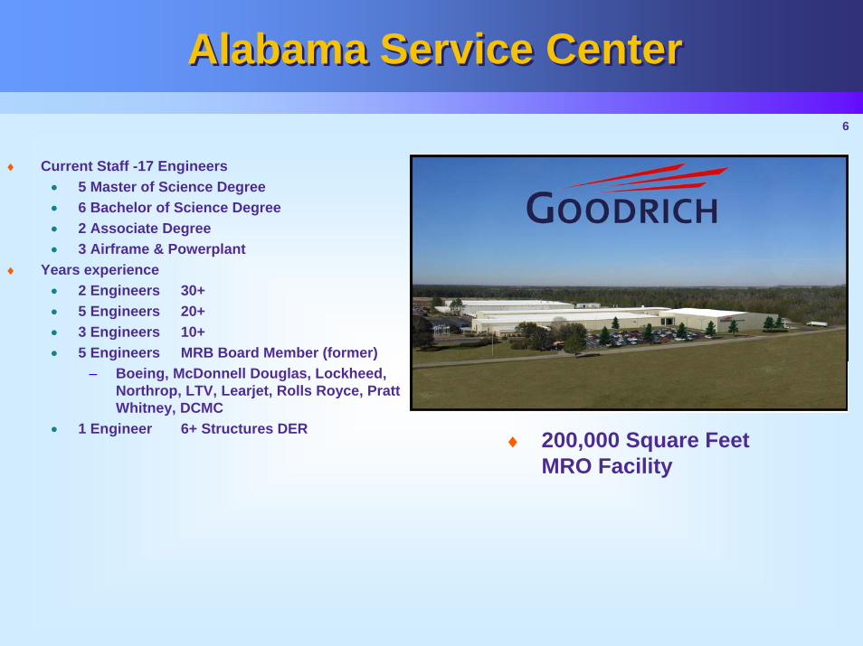
Alabama Service CenterAlabama Service Center
♦ Current Staff -17 Engineers• 5 Master of Science Degree• 6 Bachelor of Science Degree • 2 Associate Degree• 3 Airframe & Powerplant
♦ Years experience• 2 Engineers 30+• 5 Engineers 20+• 3 Engineers 10+• 5 Engineers MRB Board Member (former)
– Boeing, McDonnell Douglas, Lockheed, Northrop, LTV, Learjet, Rolls Royce, Pratt Whitney, DCMC
• 1 Engineer 6+ Structures DER♦ 200,000 Square Feet
MRO Facility
7
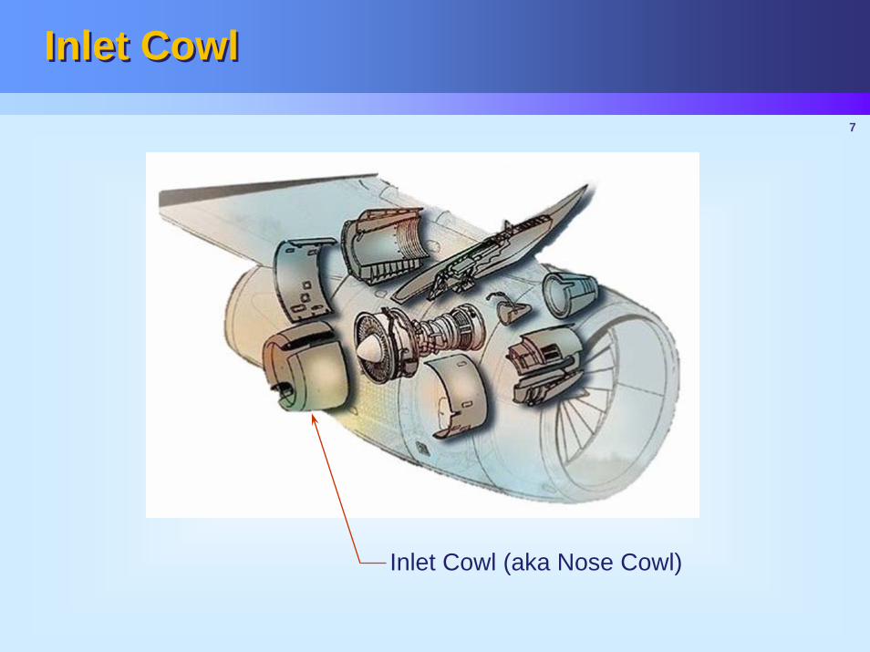
Inlet CowlInlet Cowl
Inlet Cowl (aka Nose Cowl)
8
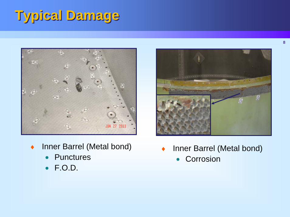
Typical DamageTypical Damage
♦ Inner Barrel (Metal bond)• Punctures • F.O.D.
♦ Inner Barrel (Metal bond)• Corrosion

9
DrainageDrainage
♦ Slotted core on 6 O’clock panel
♦ Conventional, sectional replacement of this core would destroy the panel's ability to drain
10
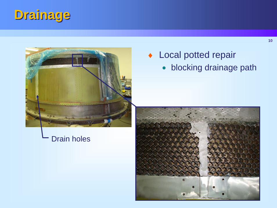
DrainageDrainage
Drain holes
♦ Local potted repair• blocking drainage path
11
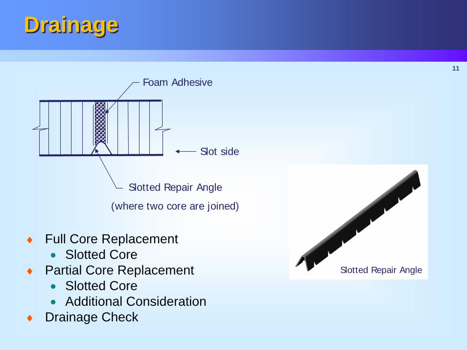
DrainageDrainage
Slot side
Slotted Repair Angle
(where two core are joined)
Foam Adhesive
Slotted Repair Angle
♦ Full Core Replacement• Slotted Core
♦ Partial Core Replacement• Slotted Core• Additional Consideration
♦ Drainage Check
12
AcousticAcoustic
♦ Acoustic Requirements must be maintained
- Noise Emission
- FAA Regulation- Part 36 and part 21.93
13
AcousticAcoustic
♦ Key elements in acoustic panel• Honeycomb core
– Cell Size/Depth– Conventional or septum
• Perforated skin– Perforated hole size– Reticulation– Wire
14
AcousticAcoustic
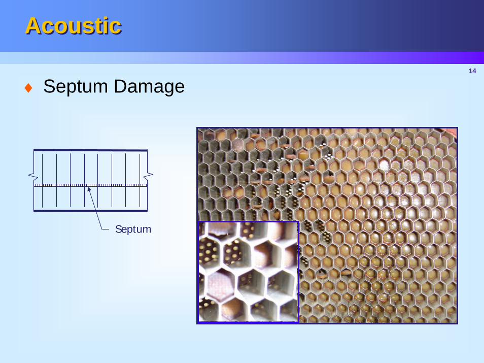
Septum
♦ Septum Damage
15
AcousticAcoustic
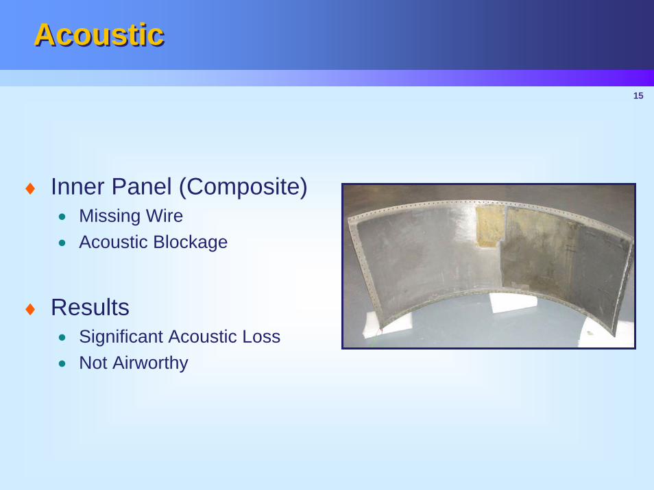
♦ Inner Panel (Composite)• Missing Wire• Acoustic Blockage
♦ Results• Significant Acoustic Loss• Not Airworthy

16
AcousticAcoustic
Wire bonded with paste adhesive
Significant blockage in perforated skin
17
AcousticAcoustic
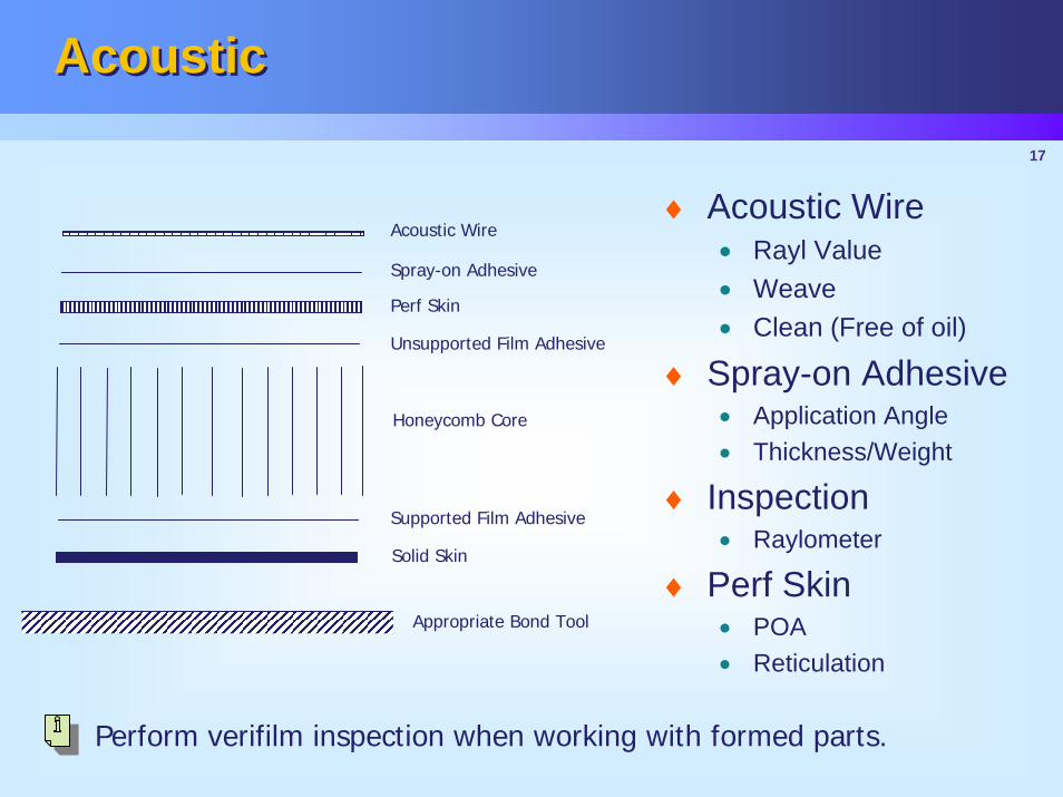
Acoustic Wire
Solid Skin
Spray-on Adhesive
Perf Skin
Unsupported Film Adhesive
Honeycomb Core
Supported Film Adhesive
Appropriate Bond Tool
Perform verifilm inspection when working with formed parts.
♦ Acoustic Wire• Rayl Value• Weave• Clean (Free of oil)
♦ Spray-on Adhesive• Application Angle• Thickness/Weight
♦ Inspection• Raylometer
♦ Perf Skin• POA• Reticulation
18
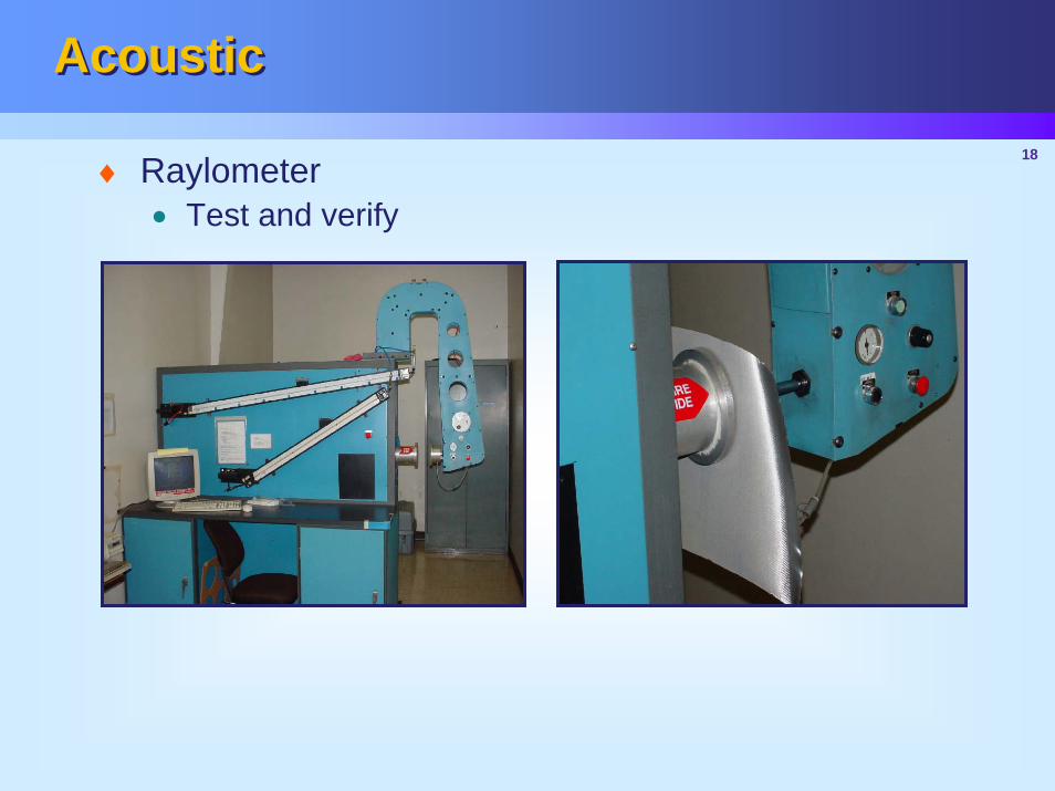
AcousticAcoustic
♦ Raylometer• Test and verify

19
AcousticAcoustic
Reticulating perf skin
Do not brush-on paste adhesive.
Reticulating core
♦ Maintain Original Reticulation Method
20
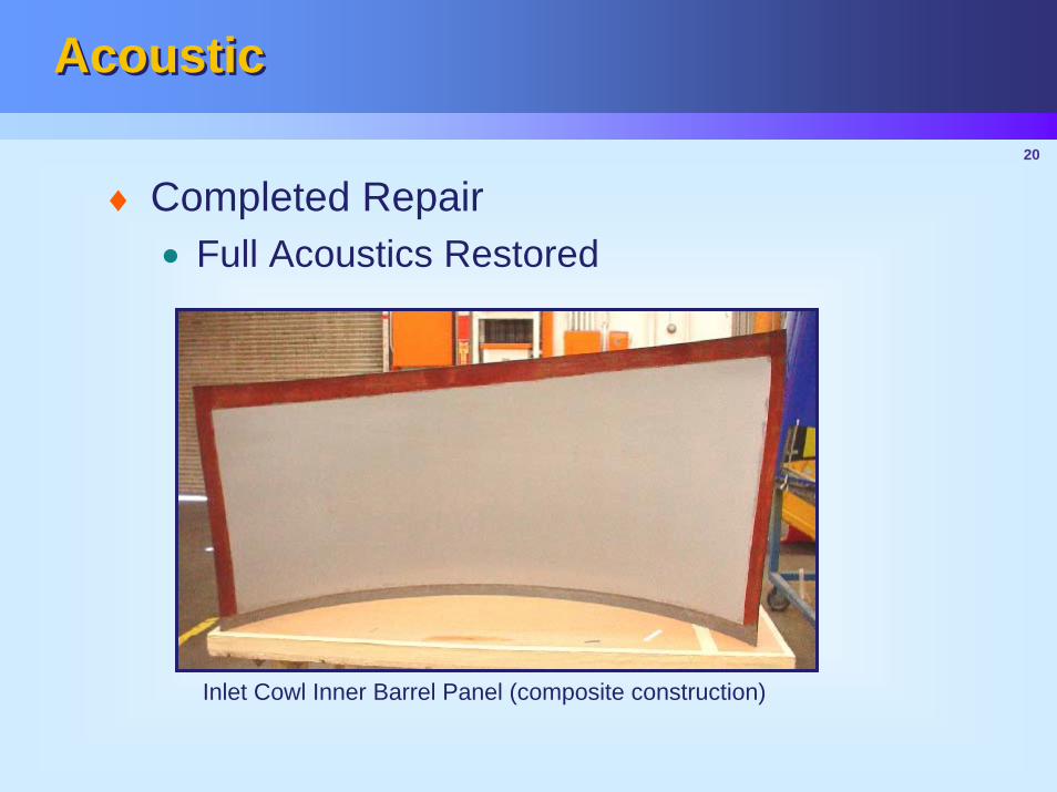
AcousticAcoustic
Inlet Cowl Inner Barrel Panel (composite construction)
♦ Completed Repair• Full Acoustics Restored
21
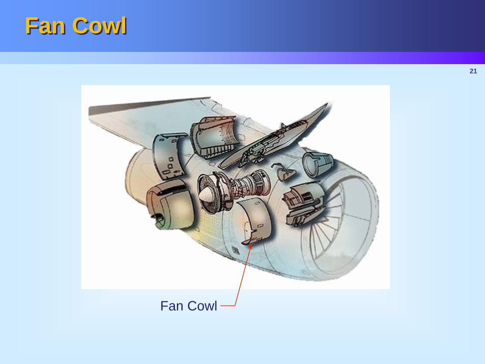
Fan CowlFan Cowl
Fan Cowl
22
Lightening Strike ProtectionLightening Strike Protection
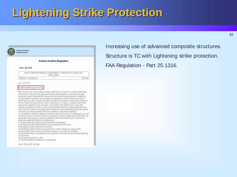
Increasing use of advanced composite structures.
Structure is TC with Lightening strike protection.
FAA Regulation - Part 25.1316.
23
Lightening Strike Protection Lightening Strike Protection
♦ Effects• EBU Systems• Degradation of structural material properties • Split open skin/structure• Explosive ignition of flammable vapors
♦ Indication of lightening strike damage• Local vaporization of the structure • Burn marks• Electro-mechanical deformation (metallic structure)
24
Lightening Strike ProtectionLightening Strike Protection
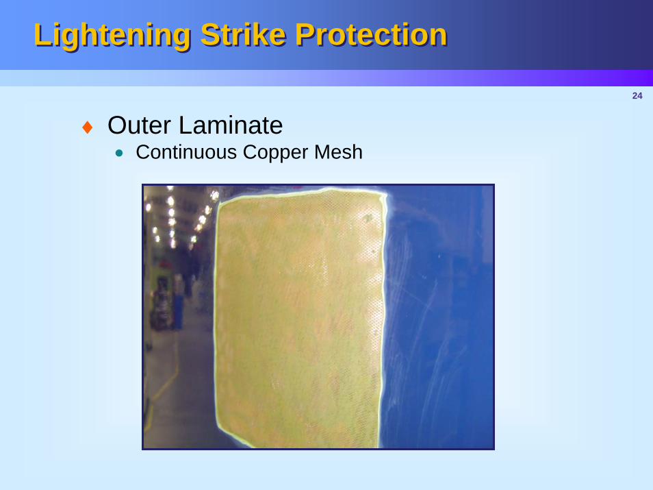
♦ Outer Laminate• Continuous Copper Mesh

25
Lightening Strike ProtectionLightening Strike Protection
Discontinuities in the lightening current flow path such as adhesive joints must be bridged by a conductive path.
Foam AdhesiveConductive Grid
♦ Core• Conductive Grid over core splices
26
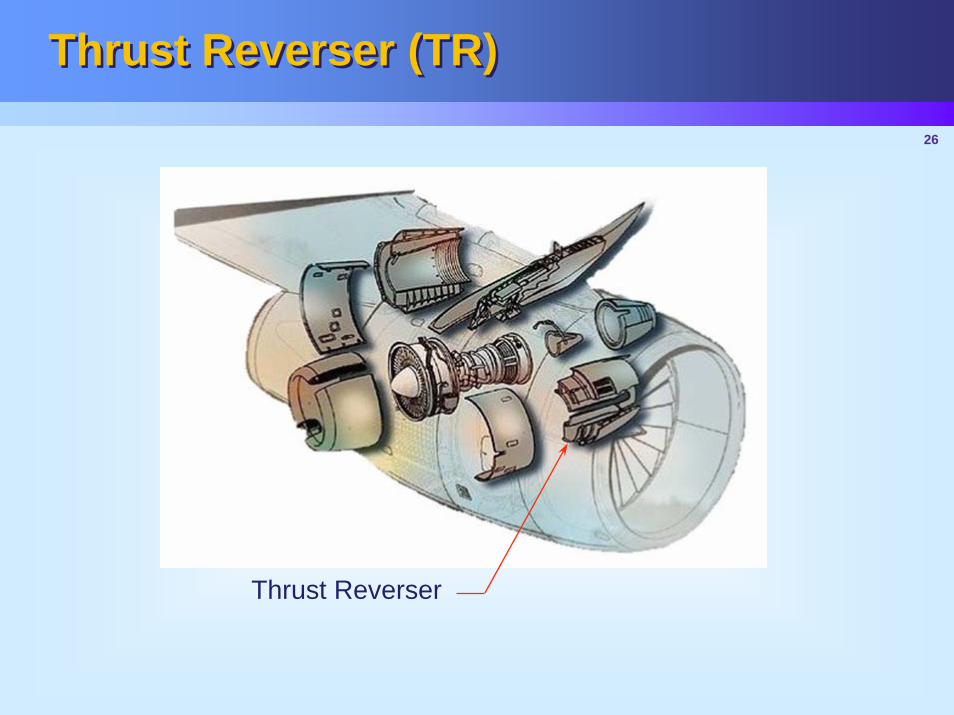
Thrust Reverser (TR) Thrust Reverser (TR)
Thrust Reverser
27
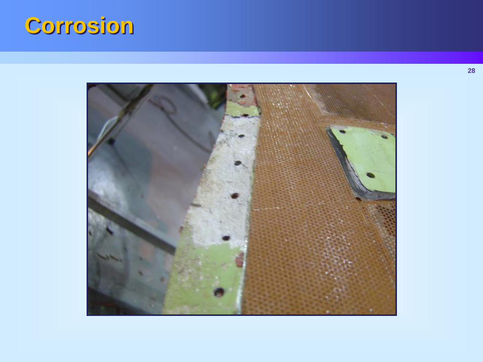
CorrosionCorrosion
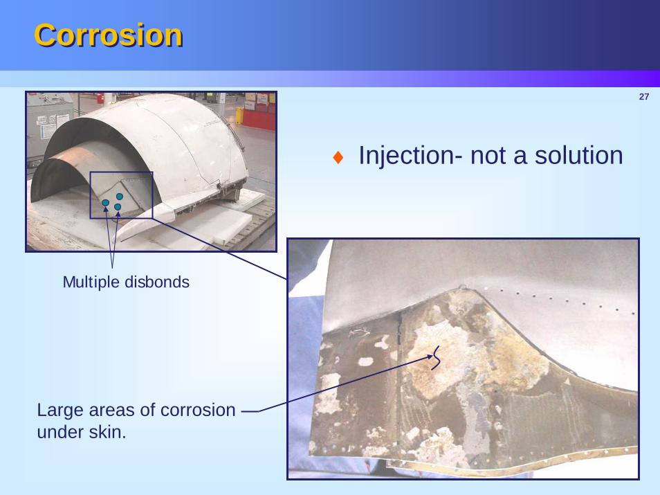
Large areas of corrosion under skin.
Multiple disbonds
♦ Injection- not a solution
28
CorrosionCorrosion
29
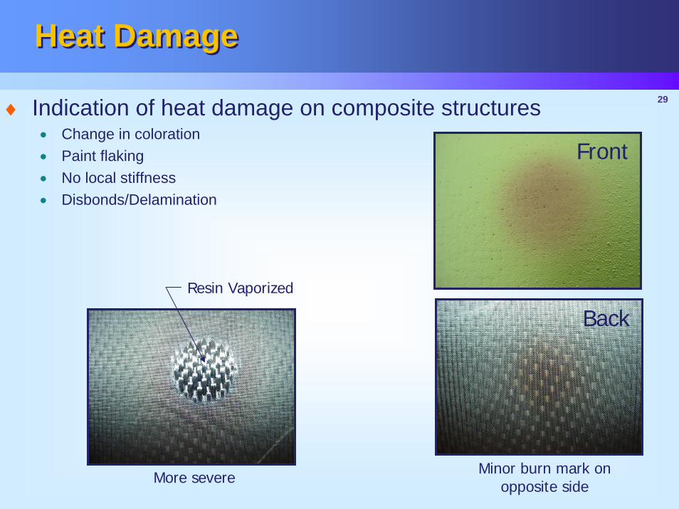
Heat DamageHeat Damage
Minor burn mark on opposite sideMore severe
Resin Vaporized
♦ Indication of heat damage on composite structures• Change in coloration • Paint flaking• No local stiffness • Disbonds/Delamination
Front
Back
30
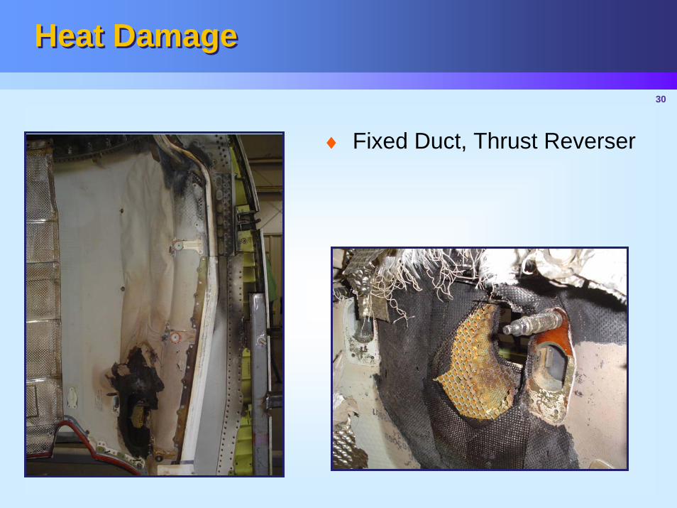
Heat DamageHeat Damage
♦ Fixed Duct, Thrust Reverser
31
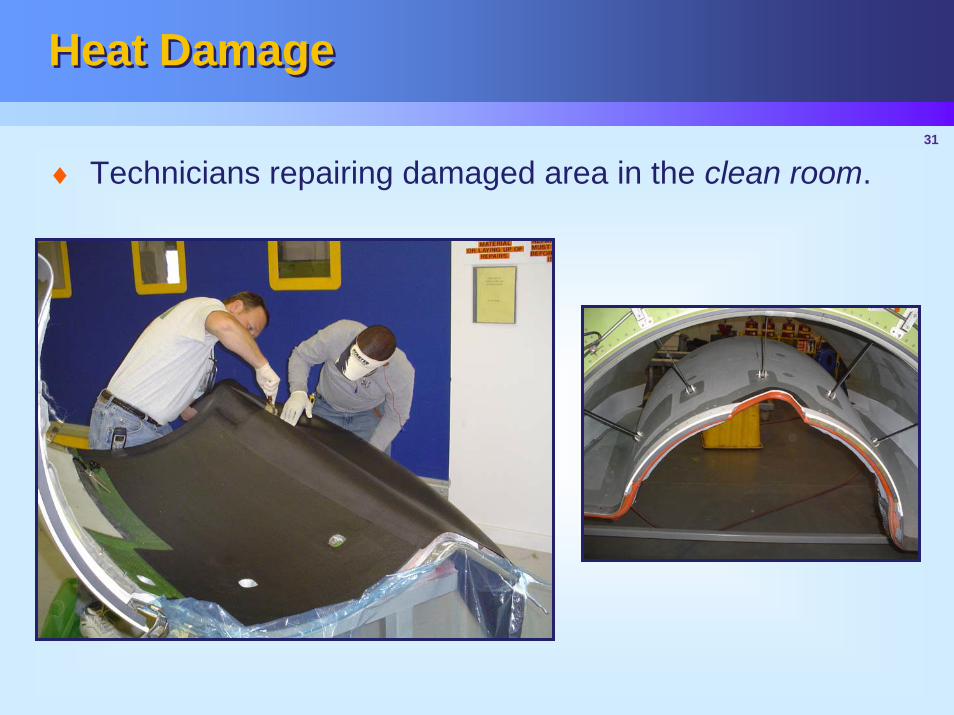
Heat DamageHeat Damage
♦ Technicians repairing damaged area in the clean room.
32
SummarySummary
♦ Nacelle Repair Considerations• Drainage• Acoustics• Lightening Strike Protection• Corrosion• Heat Damage
♦ Questions?