Embed Size (px)
Citation preview
Damage Arresting Composites Using Interlaminar Stitches
Dawn JegleyStructural Mechanics and Concepts Branch
Research DirectorateNASA Langley Research Center
The Composites ConsortiumApril 29-30, 2015
https://ntrs.nasa.gov/search.jsp?R=20160007088 2018-06-23T02:58:51+00:00Z
Outline
2
• Background
• Value of through-the-thickness stitching
• Current structural concept
• Panel fabrication methodology
• Assembly into test article and structural performance

Participants
3
• Stitched structure development was initiated under the Advanced Composites Technology (ACT) Program between NASA and McDonnell Douglas Company in the 1990’s
• Continued development with the Boeing Company (Boeing) and the Air Force Research Lab (AFRL) in the early 2000’s when the current structural concept was born
• New partnership formed in 2007 between NASA and Boeing which continues today under the Environmentally Responsible Aviation (ERA) Project
• Federal Aviation Administration (FAA) has also contributed to the current activity
• Under ERA, NASA and Boeing have worked together on design, analysis and testing, but all fabrication has been done by Boeing Research and Technology
Goals of the ERA Project
4
• Develop technology for commercial transport aircraft to simultaneously reduce:• Fuel consumption• Pollution• Community noise
• Develop technologies supporting conventional aircraft and new aircraft configurations
• Aim for technologies that could be implemented in the 2025 to 2030 time period• Run the Project over 2009-2015
Composites for Aircraft
5
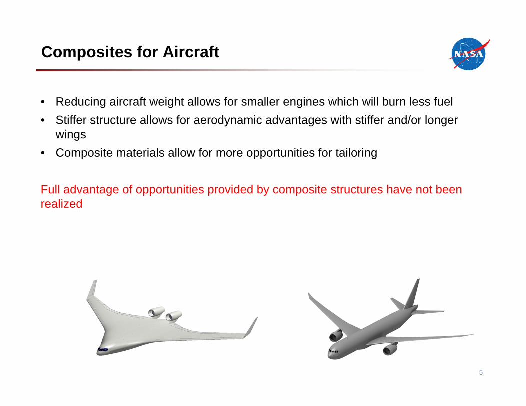
• Reducing aircraft weight allows for smaller engines which will burn less fuel• Stiffer structure allows for aerodynamic advantages with stiffer and/or longer
wings• Composite materials allow for more opportunities for tailoring
Full advantage of opportunities provided by composite structures have not been realized
Stitched Composites Project Objective
6
Develop technology to reduce aircraft weight by 10 percent over state-of-the-art composites while maintaining safety margins and supporting advanced aircraft configurations
Design with Stitched Structure
7
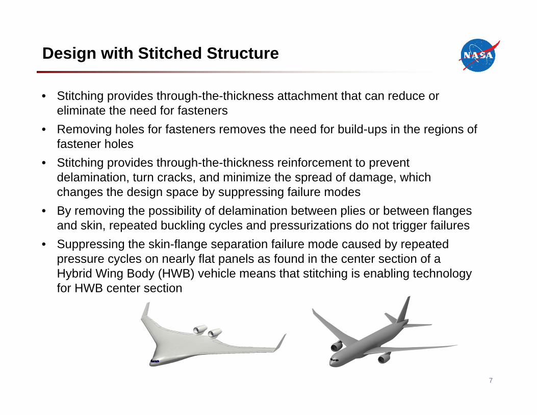
• Stitching provides through-the-thickness attachment that can reduce or eliminate the need for fasteners
• Removing holes for fasteners removes the need for build-ups in the regions of fastener holes
• Stitching provides through-the-thickness reinforcement to prevent delamination, turn cracks, and minimize the spread of damage, which changes the design space by suppressing failure modes
• By removing the possibility of delamination between plies or between flanges and skin, repeated buckling cycles and pressurizations do not trigger failures
• Suppressing the skin-flange separation failure mode caused by repeated pressure cycles on nearly flat panels as found in the center section of a Hybrid Wing Body (HWB) vehicle means that stitching is enabling technology for HWB center section
8
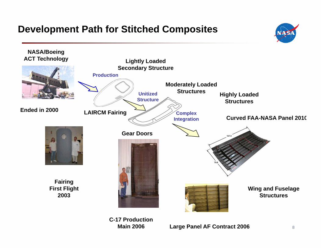
Development Path for Stitched Composites
LAIRCM Fairing
Gear Doors
Lightly Loaded Secondary Structure
Moderately Loaded Structures Highly Loaded
StructuresUnitized
Structure
Complex Integration
Production
Large Panel AF Contract 2006
FairingFirst Flight
2003
NASA/BoeingACT Technology
Ended in 2000
C-17 ProductionMain 2006
Curved FAA-NASA Panel 2010
Wing and Fuselage Structures
Advanced Structures
9
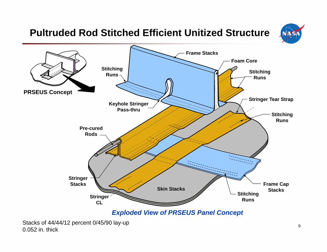
Pre-cured Rods
Keyhole Stringer Pass-thru
Foam CoreFrame Stacks
Stitching Runs
Frame Cap Stacks
Stitching Runs
Skin Stacks
Stringer Tear Strap
Stitching Runs
Stringer Stacks
Stringer CL
Stitching Runs
PRSEUS Concept
Exploded View of PRSEUS Panel Concept Stacks of 44/44/12 percent 0/45/90 lay-up 0.052 in. thick
Pultruded Rod Stitched Efficient Unitized Structure
Unitized Stitched Structures
• Large integral components• Out-of-autoclave process (oven with vacuum pressure only)• Dry fabric removes out time issues associated with prepreg• Fabricate entire wing cover panel or entire upper section of fuselage in one cure• Hard metal tooling on outer moldline (OML) only• Simplified bagging process for inner moldline (IML)
10

Building Block Testing
11
Trades Studies
• Panel Geometry
• Weight Goals• TestLoads
• Stability
TensionLoading
• DamageArrestment
• Repair
Flexure Coupons Pressure Panel Pressure Cube
Pressure Loading
• StringerStability
• Post-Buckled Structures
HWB Multi-Bay Test Article
• Strength
Compression Loading
• Biaxial Loading
• Adhesion
• Frame Stability
• Fail-Safe
Mid 2015 Test at NASA-LaRC
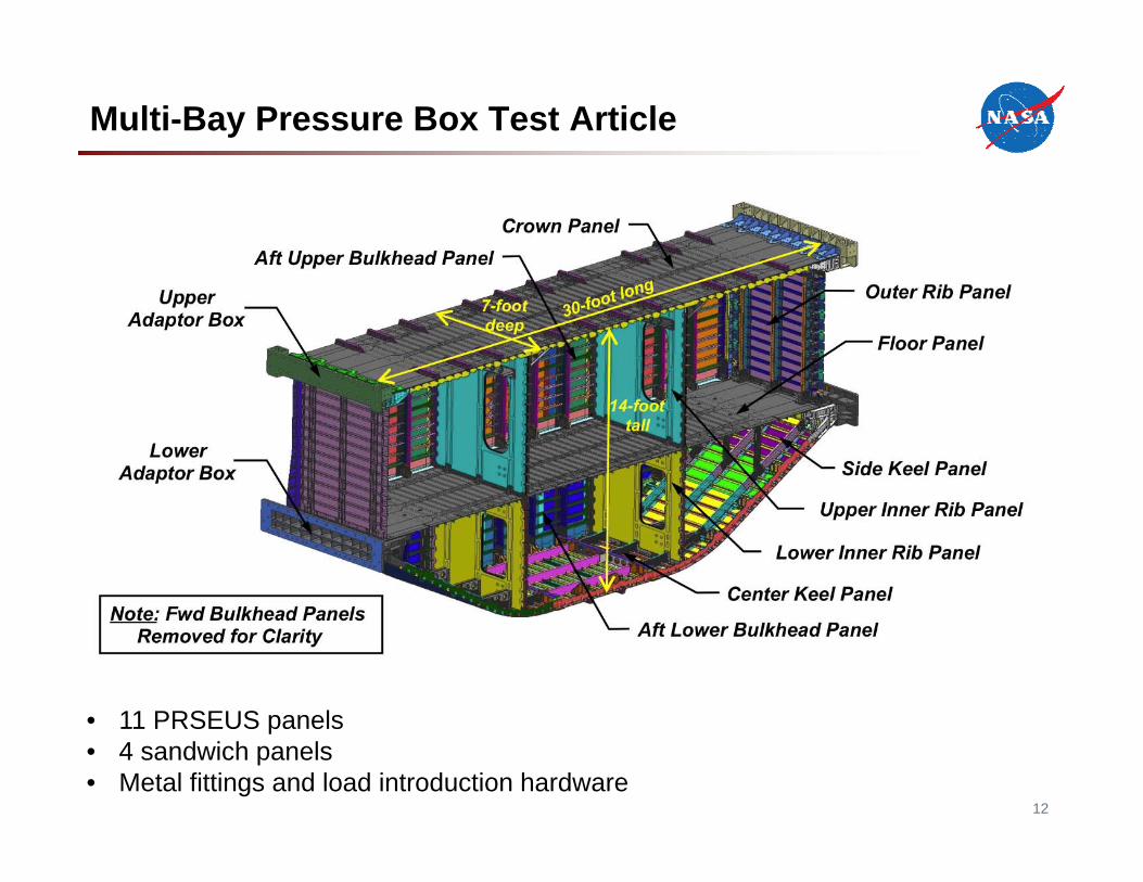
Multi-Bay Pressure Box Test Article
12
• 11 PRSEUS panels• 4 sandwich panels• Metal fittings and load introduction hardware
13
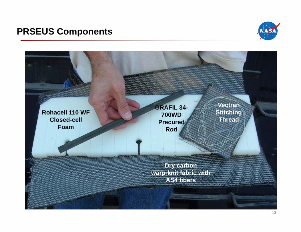
PRSEUS Components
Rohacell 110 WF Closed-cell
Foam
Dry carbonwarp-knit fabric with
AS4 fibers
VectranStitching Thread
GRAFIL 34-700WD
PrecuredRod
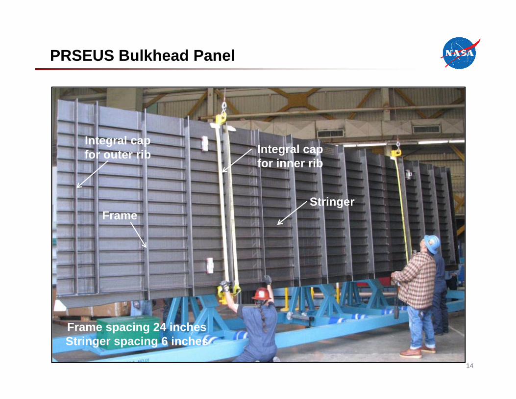
PRSEUS Bulkhead Panel
14
Integral cap for outer rib
FrameStringer
Integral cap for inner rib
Frame spacing 24 inchesStringer spacing 6 inches

15
Lower Bulkhead Panel 1
Floor Panel
Outer Rib 2
Upper Bulkhead 1
Center Rib Panel (4)
Outer Rib 1
Upper Bulkhead 2
Crown Panel
Side Keel Panel 1
Center Keel Panel
Lower Bulkhead Panel 2
Side Keel Panel 2
Panels for the Multi-Bay Pressure Box
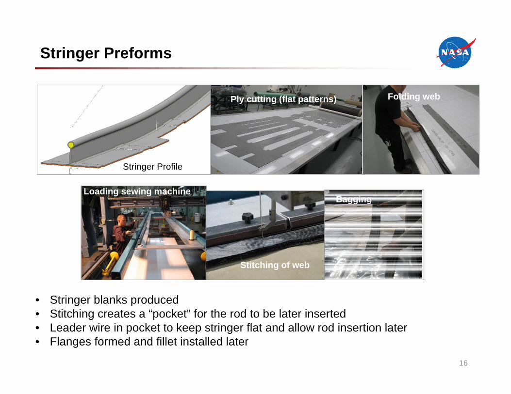
Stringer Preforms
Ply cutting (flat patterns) Folding web
Loading sewing machine
Stitching of web
Bagging
• Stringer blanks produced• Stitching creates a “pocket” for the rod to be later inserted• Leader wire in pocket to keep stringer flat and allow rod insertion later• Flanges formed and fillet installed later
Stringer Profile
16
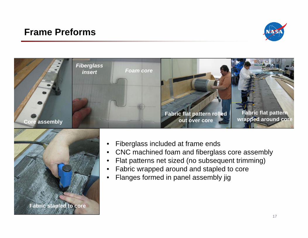
Frame Preforms
Fiberglass insert Foam core
• Fiberglass included at frame ends• CNC machined foam and fiberglass core assembly• Flat patterns net sized (no subsequent trimming)• Fabric wrapped around and stapled to core• Flanges formed in panel assembly jig
Core assembly
Fabric stapled to core
Fabric flat pattern rolled out over core
Fabric flat pattern wrapped around core
17
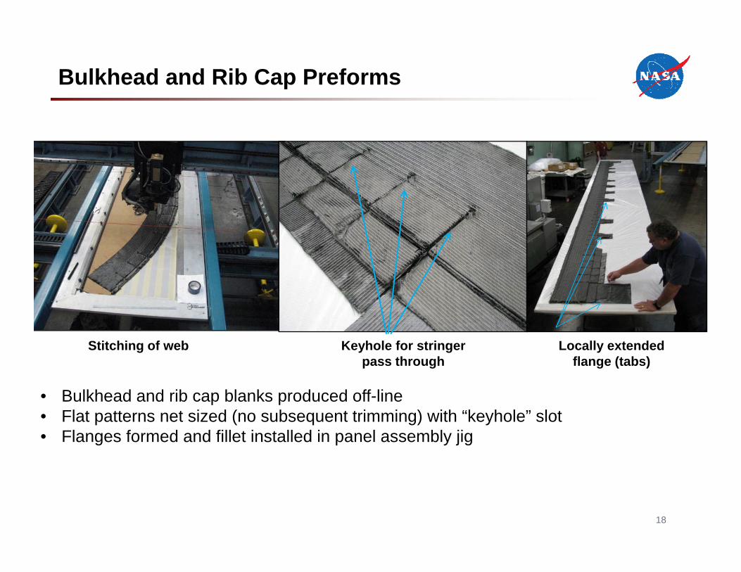
Bulkhead and Rib Cap Preforms
• Bulkhead and rib cap blanks produced off-line• Flat patterns net sized (no subsequent trimming) with “keyhole” slot • Flanges formed and fillet installed in panel assembly jig
Stitching of web Locally extended flange (tabs)
Keyhole for stringerpass through
18

Panel Preform Assembly Jig (Stitch Tools)
• Position and hold near net shape preforms for subsequent assembly stitching• CNC machine foam blocks and wood details• Pinned and bolted to steel base in robot cell
19
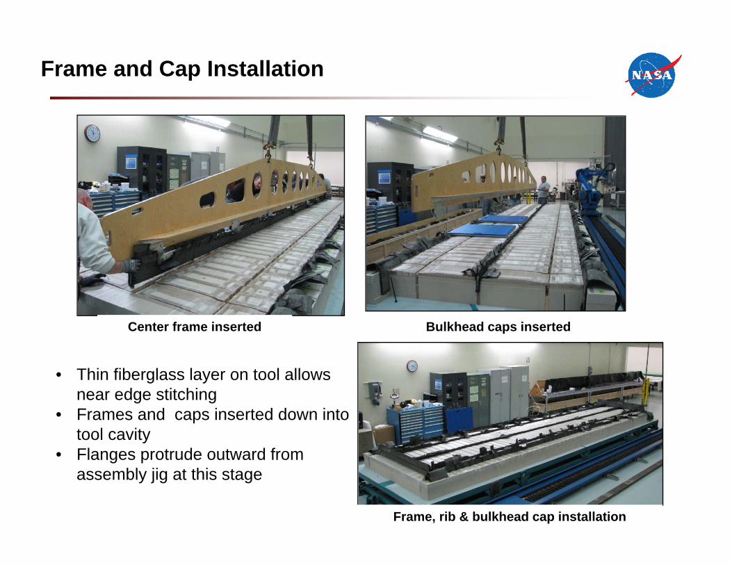
Frame and Cap Installation
• Thin fiberglass layer on tool allows near edge stitching
• Frames and caps inserted down into tool cavity
• Flanges protrude outward from assembly jig at this stage
20
Bulkhead caps insertedCenter frame inserted
Frame, rib & bulkhead cap installation
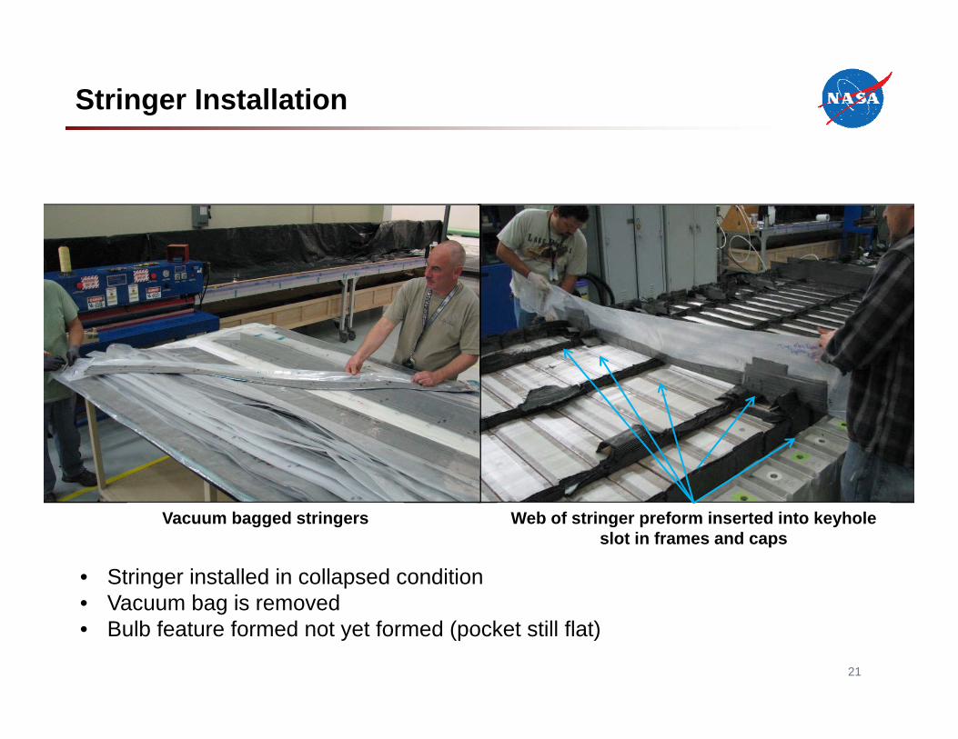
Stringer Installation
Vacuum bagged stringers Web of stringer preform inserted into keyhole slot in frames and caps
21
• Stringer installed in collapsed condition• Vacuum bag is removed• Bulb feature formed not yet formed (pocket still flat)
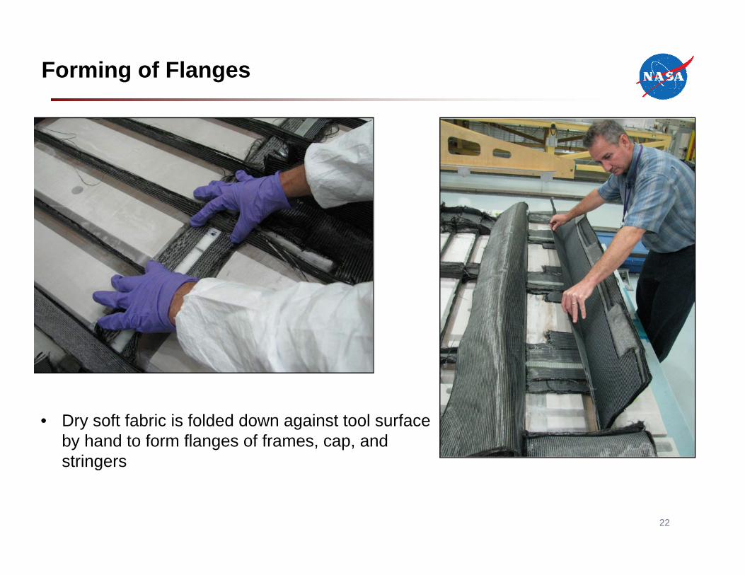
Forming of Flanges
22
• Dry soft fabric is folded down against tool surface by hand to form flanges of frames, cap, and stringers
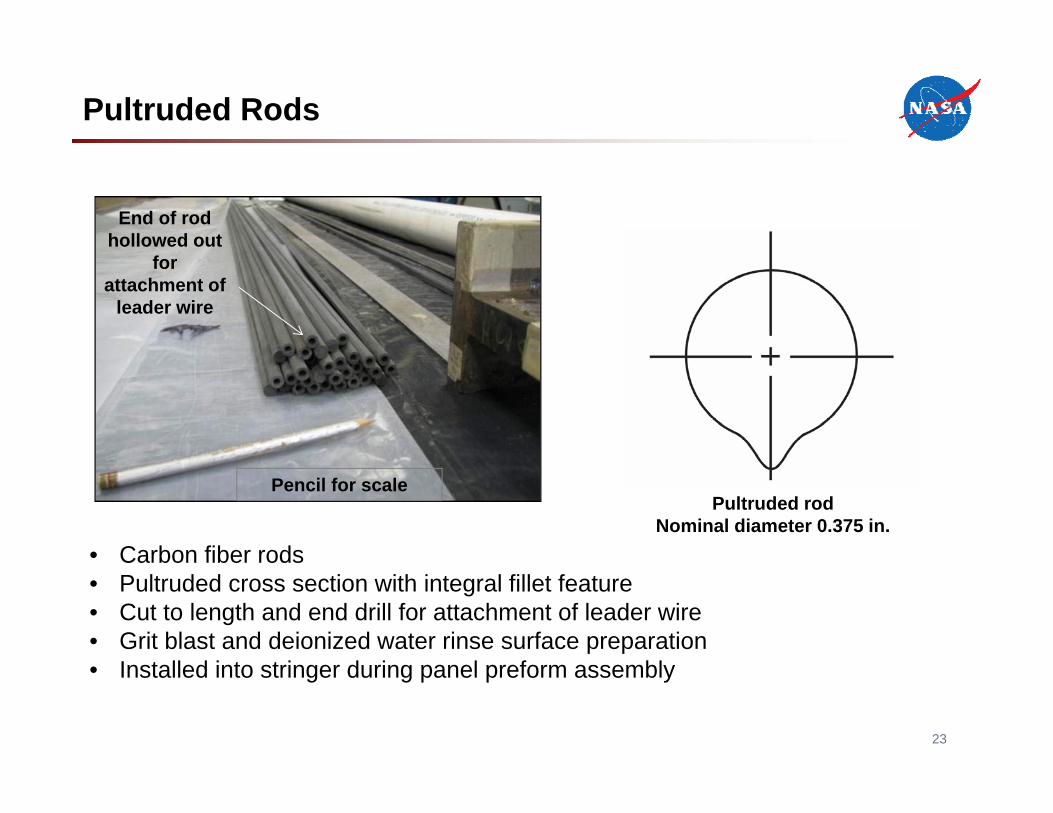
Pultruded Rods
• Carbon fiber rods• Pultruded cross section with integral fillet feature• Cut to length and end drill for attachment of leader wire• Grit blast and deionized water rinse surface preparation• Installed into stringer during panel preform assembly
23
Pultruded rodNominal diameter 0.375 in.
Pencil for scale
End of rod hollowed out
for attachment of
leader wire
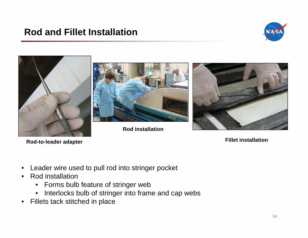
Rod and Fillet Installation
Fillet installationRod-to-leader adapter
24
Rod installation
• Leader wire used to pull rod into stringer pocket• Rod installation
• Forms bulb feature of stringer web• Interlocks bulb of stringer into frame and cap webs
• Fillets tack stitched in place
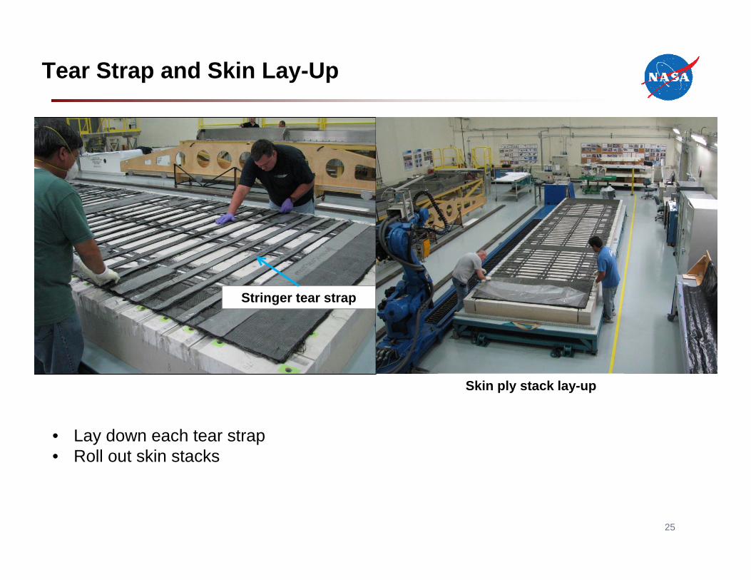
Tear Strap and Skin Lay-Up
Stringer tear strap
25
Skin ply stack lay-up
• Lay down each tear strap• Roll out skin stacks
26
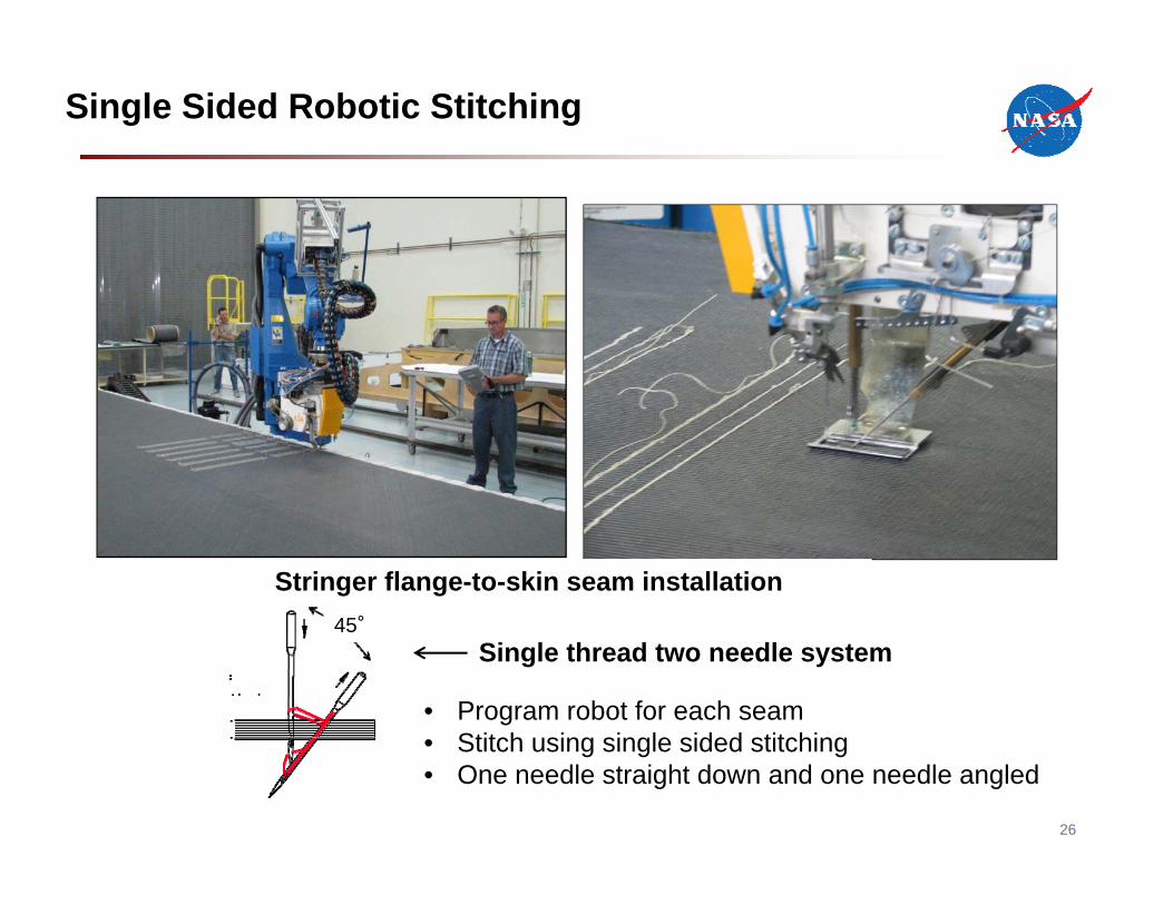
Single Sided Robotic Stitching
Single-sided Stitching
Single thread two needle system
Stringer flange-to-skin seam installation
• Program robot for each seam• Stitch using single sided stitching• One needle straight down and one needle angled
45°
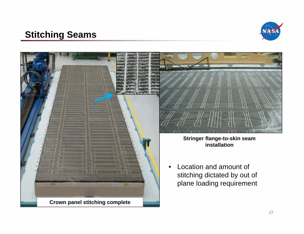
Stitching Seams
27
Stringer flange-to-skin seam installation
Crown panel stitching complete
• Location and amount of stitching dictated by out of plane loading requirement
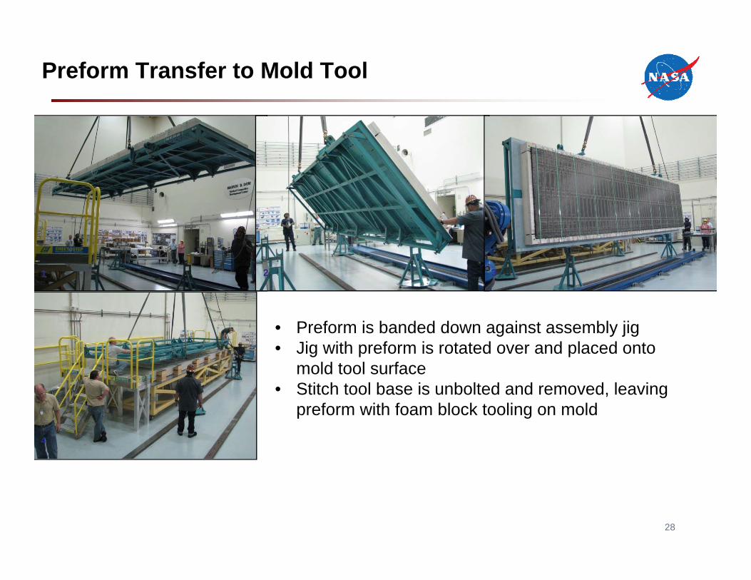
Preform Transfer to Mold Tool
28
1 2 3
4
• Preform is banded down against assembly jig• Jig with preform is rotated over and placed onto
mold tool surface• Stitch tool base is unbolted and removed, leaving
preform with foam block tooling on mold
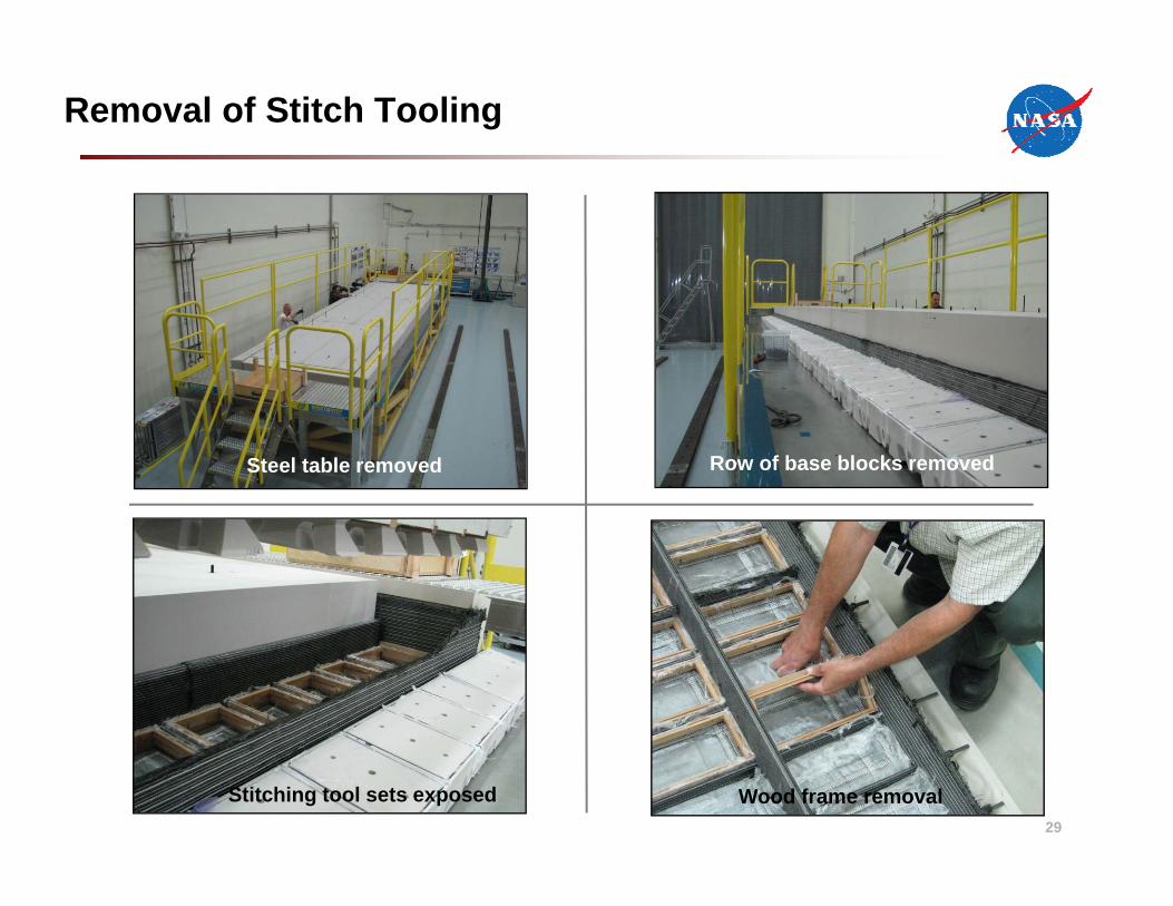
Removal of Stitch Tooling
Steel table removed
Wood frame removal
Row of base blocks removed
Stitching tool sets exposed29
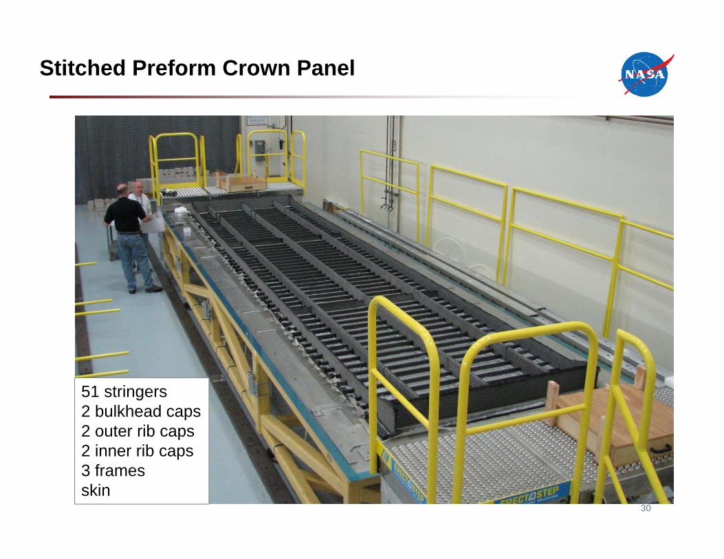
Stitched Preform Crown Panel
51 stringers2 bulkhead caps2 outer rib caps2 inner rib caps3 framesskin
30
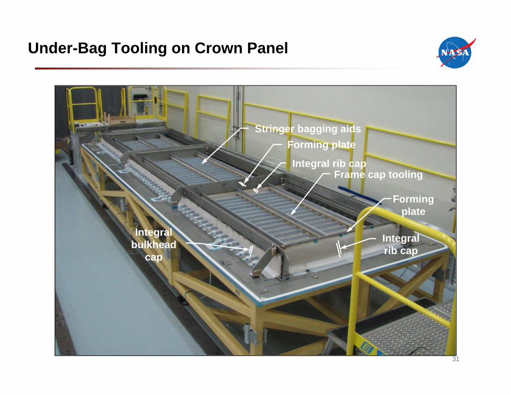
Under-Bag Tooling on Crown Panel
Frame cap tooling
Stringer bagging aids
Integral rib cap
Integral rib cap
Integral bulkhead
cap
Forming plate
Forming plate
31
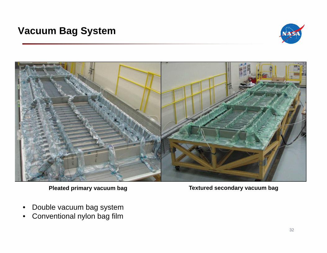
Vacuum Bag System
Pleated primary vacuum bag Textured secondary vacuum bag
32
• Double vacuum bag system• Conventional nylon bag film
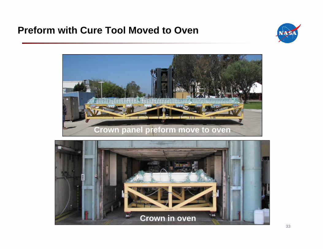
Preform with Cure Tool Moved to Oven
Photo title…
Crown panel preform move to oven
Crown in oven33
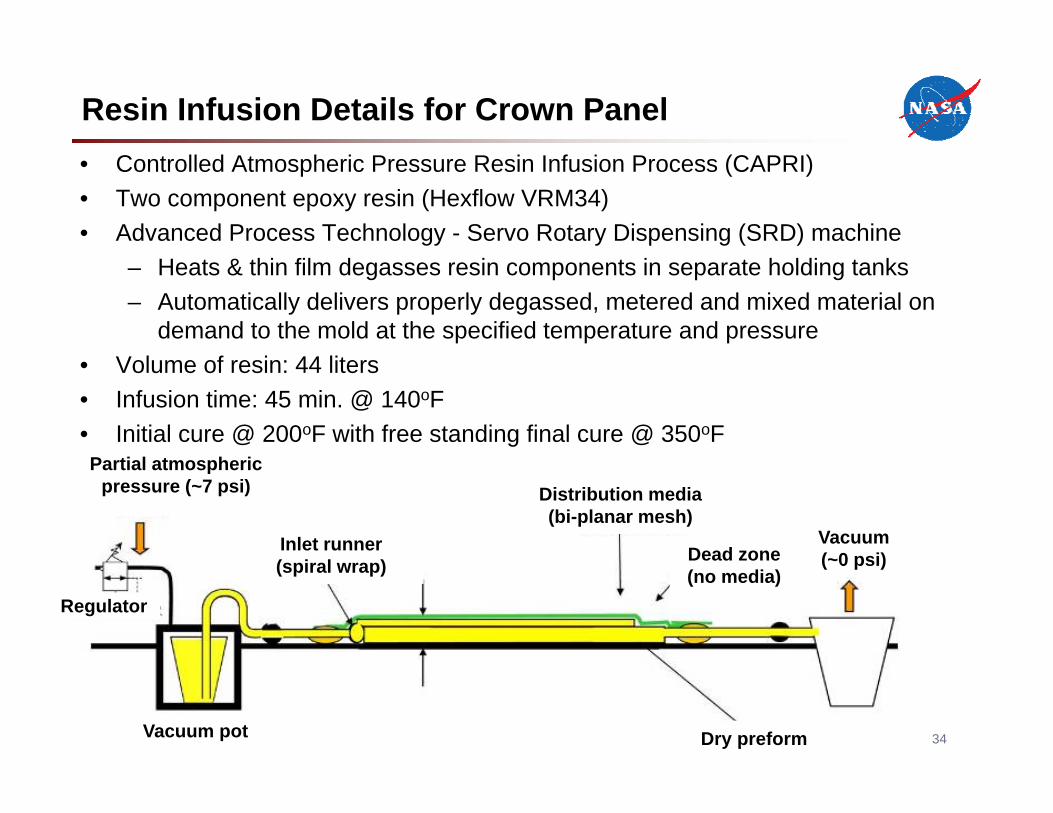
Resin Infusion Details for Crown Panel• Controlled Atmospheric Pressure Resin Infusion Process (CAPRI)• Two component epoxy resin (Hexflow VRM34)• Advanced Process Technology - Servo Rotary Dispensing (SRD) machine
– Heats & thin film degasses resin components in separate holding tanks– Automatically delivers properly degassed, metered and mixed material on
demand to the mold at the specified temperature and pressure • Volume of resin: 44 liters • Infusion time: 45 min. @ 140oF • Initial cure @ 200oF with free standing final cure @ 350oF
34
Partial atmospheric pressure (~7 psi)
Inlet runner(spiral wrap)
Distribution media (bi-planar mesh)
Dead zone(no media)
Regulator
Vacuum(~0 psi)
Dry preformVacuum pot
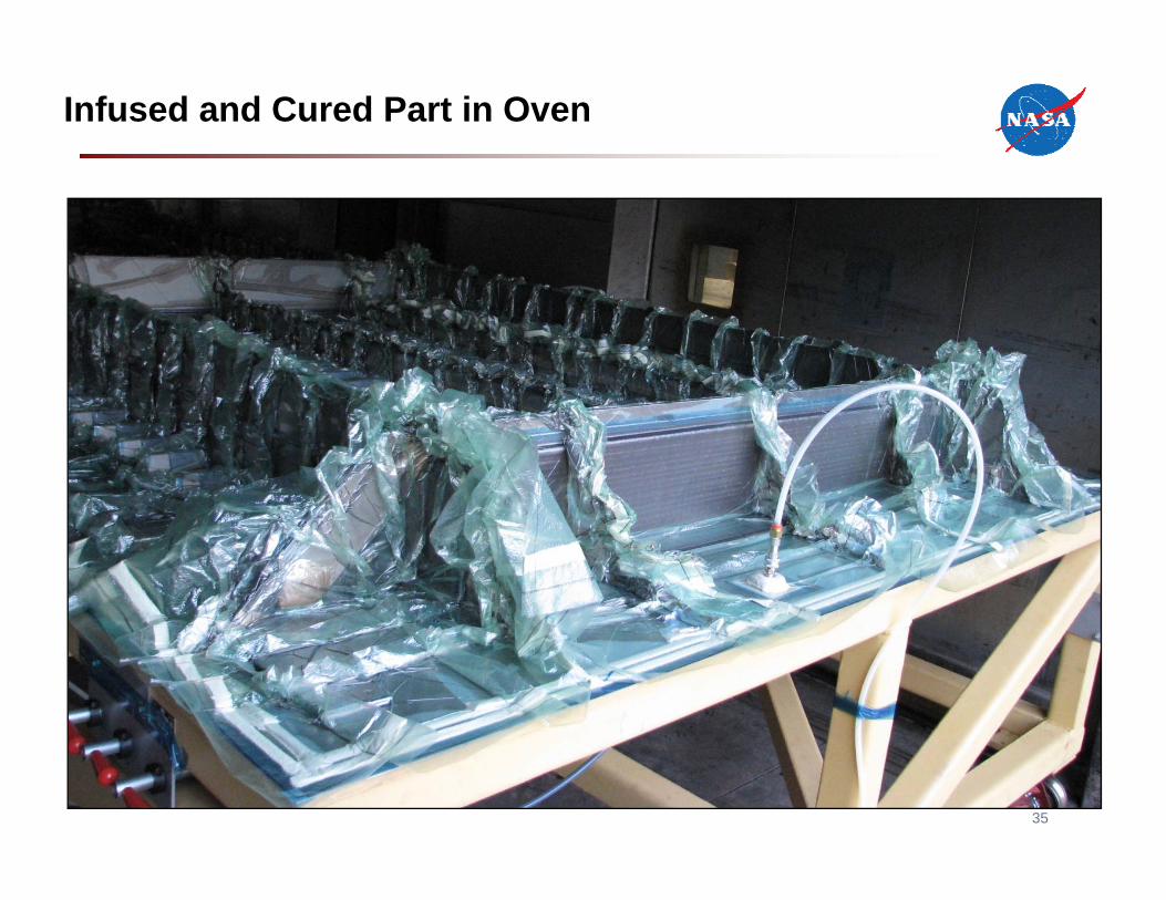
Infused and Cured Part in Oven
35
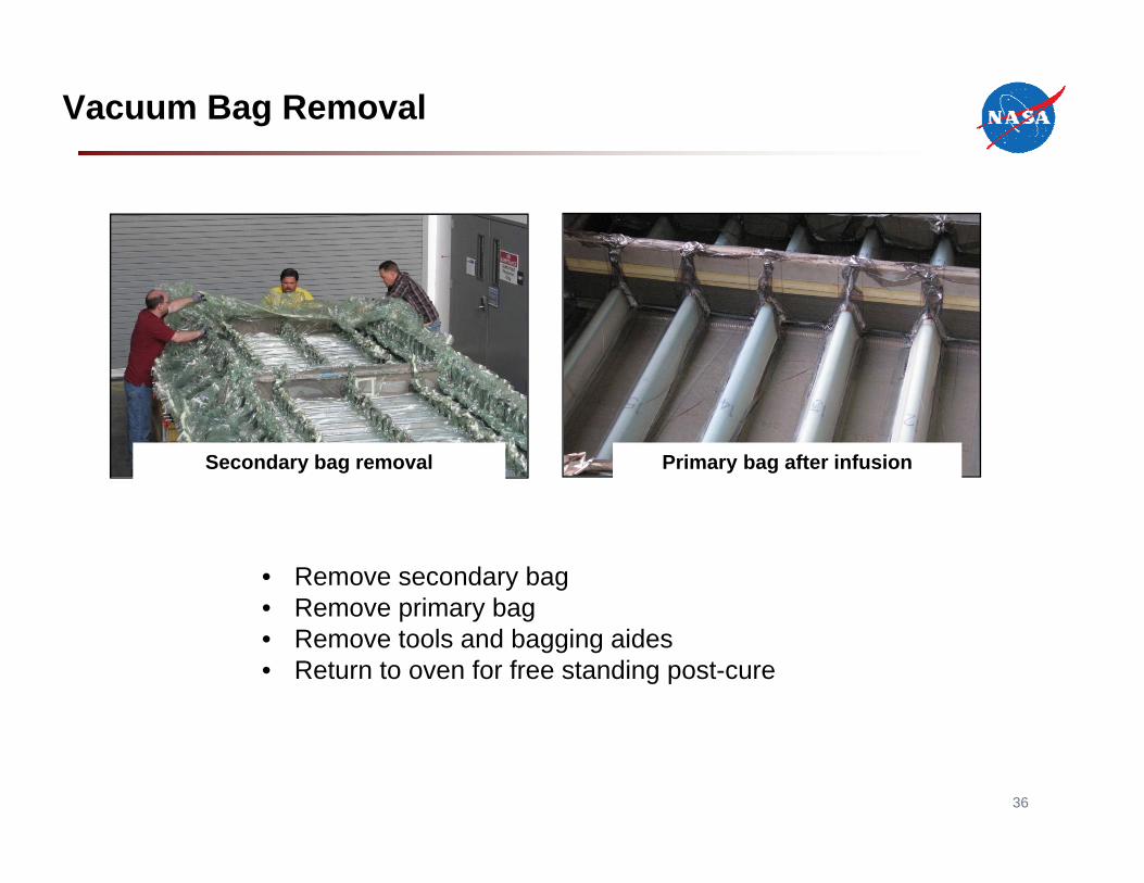
Vacuum Bag Removal
Secondary bag removal Primary bag after infusion
36
• Remove secondary bag• Remove primary bag• Remove tools and bagging aides• Return to oven for free standing post-cure
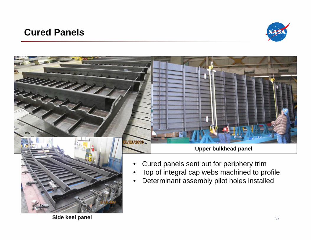
Cured Panels
Side keel panel
Upper bulkhead panel
37
• Cured panels sent out for periphery trim• Top of integral cap webs machined to profile• Determinant assembly pilot holes installed
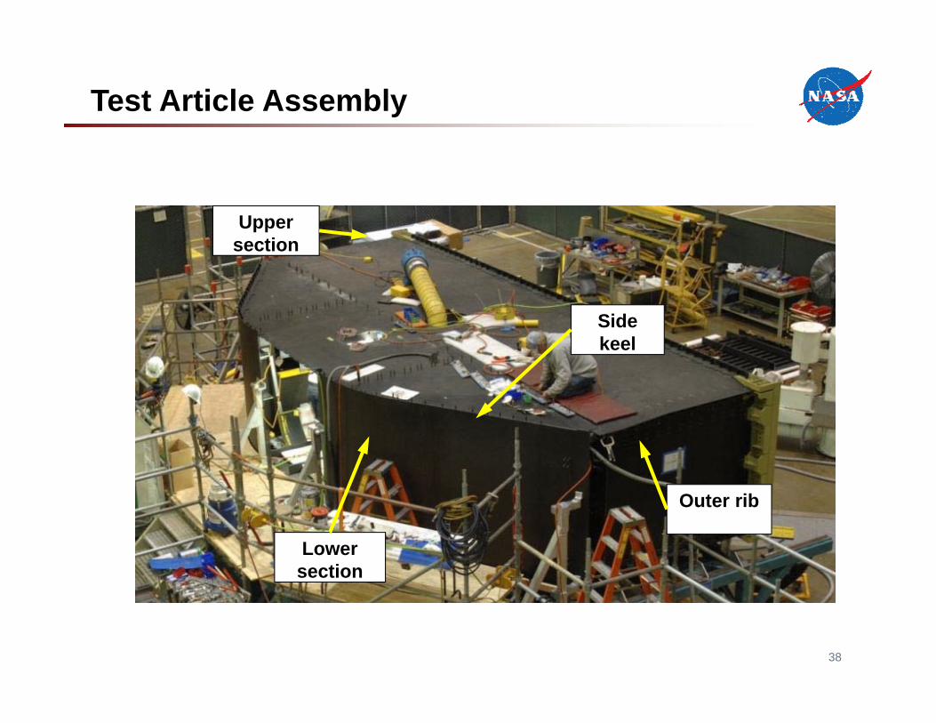
Lower section
Upper section
Side keel
Outer rib
Test Article Assembly
38
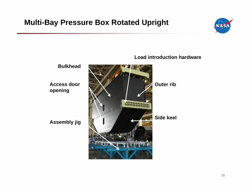
MBB in holding fixture
Assembly jig
Load introduction hardware
Access door opening
Outer rib
Side keel
Bulkhead
Multi-Bay Pressure Box Rotated Upright
39
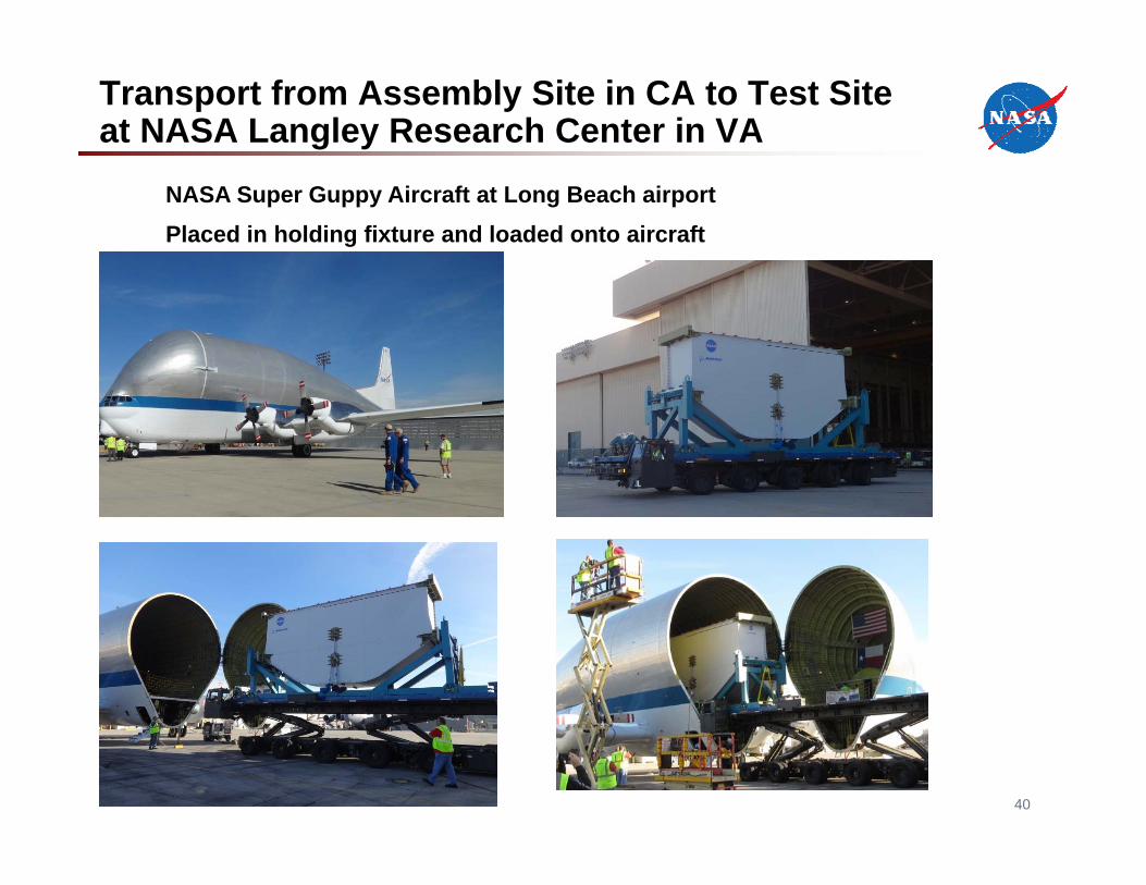
Transport from Assembly Site in CA to Test Site at NASA Langley Research Center in VA
NASA Super Guppy Aircraft at Long Beach airportPlaced in holding fixture and loaded onto aircraft
40
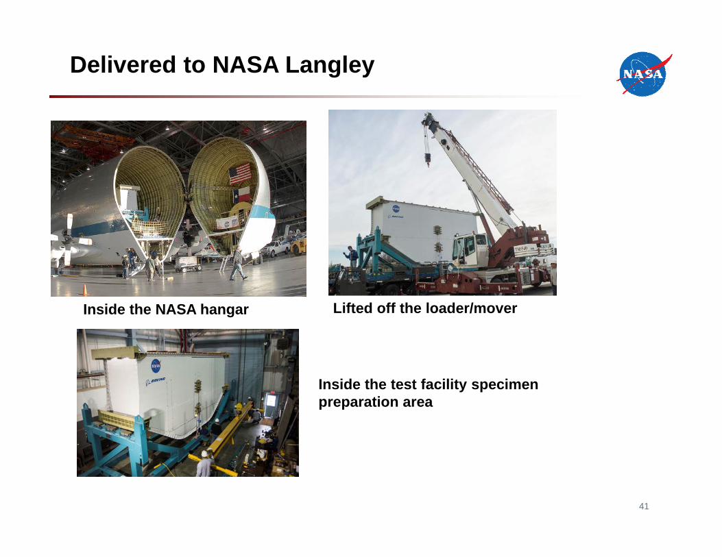
Delivered to NASA Langley
Inside the NASA hangar Lifted off the loader/mover
Inside the test facility specimen preparation area
41
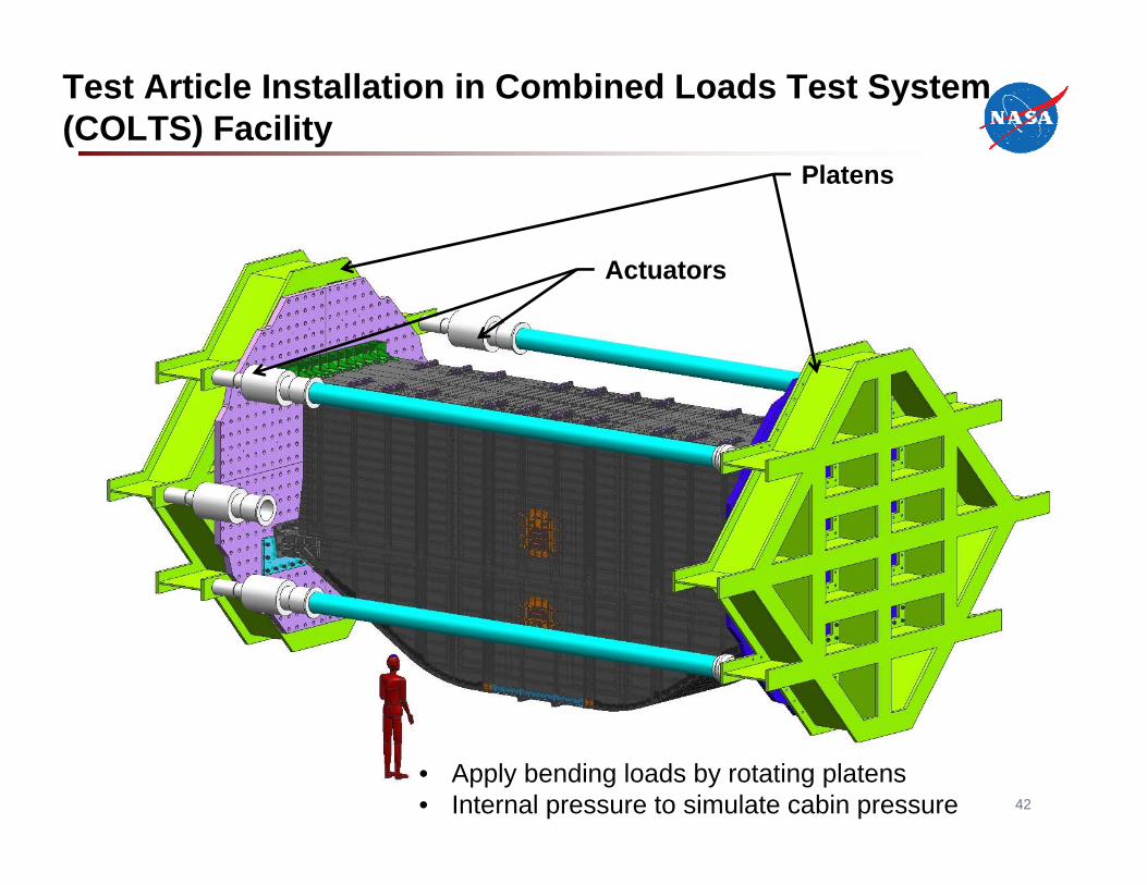
Test Article Installation in Combined Loads Test System (COLTS) Facility
42
• Apply bending loads by rotating platens• Internal pressure to simulate cabin pressure
Platens
Actuators
Platens
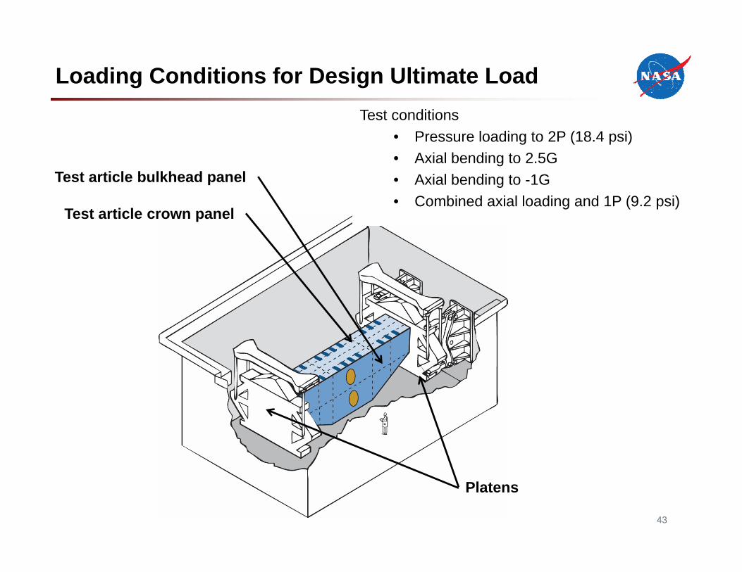
Test article crown panel
Test article bulkhead panel
Loading Conditions for Design Ultimate LoadTest conditions
• Pressure loading to 2P (18.4 psi)• Axial bending to 2.5G• Axial bending to -1G• Combined axial loading and 1P (9.2 psi)
43
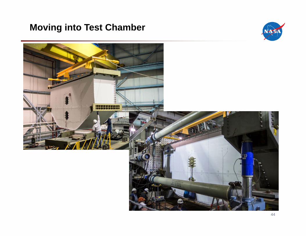
Moving into Test Chamber
44
Testing Sequence
• Load pristine structure to design ultimate load in five conditions• Inflict barely visible impact damage to exterior and interior of structure• Repeat loading to design ultimate load in five conditions• Take structure past design ultimate load to failure
45
Summary of PRSEUS Development
46
• PRSEUS development supported by NASA, Boeing, FAA and AFRL• Building block approach moving from small elements through large-scale
structure• Stitching is used to suppress interlaminar failures, arrest damage and turn
cracks• Unitized structure simplifies final assembly• Out-of-autoclave processing allows for cheaper fabrication and quicker
and easier changes to designs• Successfully fabricated 11 large PRSEUS panels and assembled into 30-
foot-long multi-bay box representing the center section of a HWB vehicle • Testing with applied bending loads and internal pressure
Acknowledgement
47
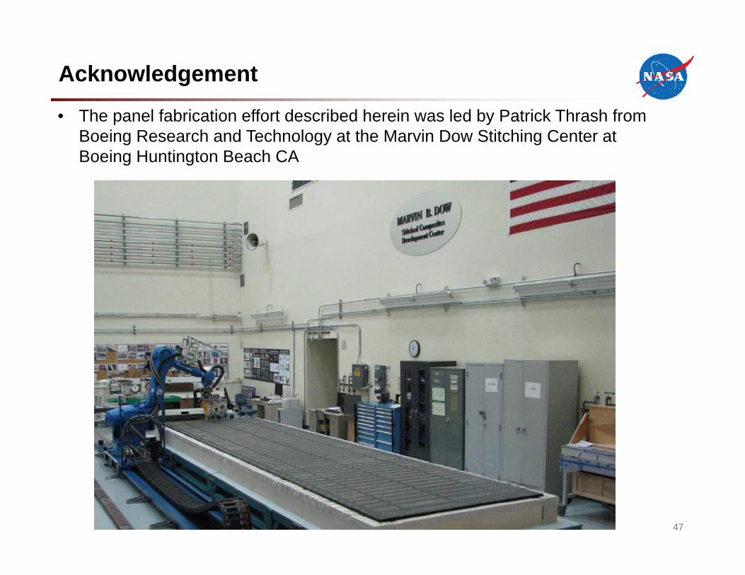
• The panel fabrication effort described herein was led by Patrick Thrash from Boeing Research and Technology at the Marvin Dow Stitching Center at Boeing Huntington Beach CA
Primary References*
48
• NASA Contractor Report 2104-218149 (final report for contract NNL13AA11C)
• CAMX SAMPE paper “Manufacturing of a Stitched Resin Infused Fuselage Test Article” from October 13-16, 2014.
• Controlled Atmospheric Pressure Resin Infusion Process, Patent EP 1507647 B1
*Publically available