Embed Size (px)
Citation preview
Data Center Energy Saving using5kV Distribution System Architecture
18 Sep 2009

Power Density Growing
www.networkcomputing.com/crash‐course‐data‐center‐power.php
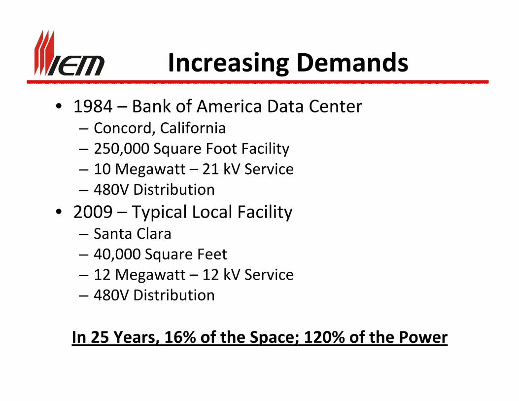
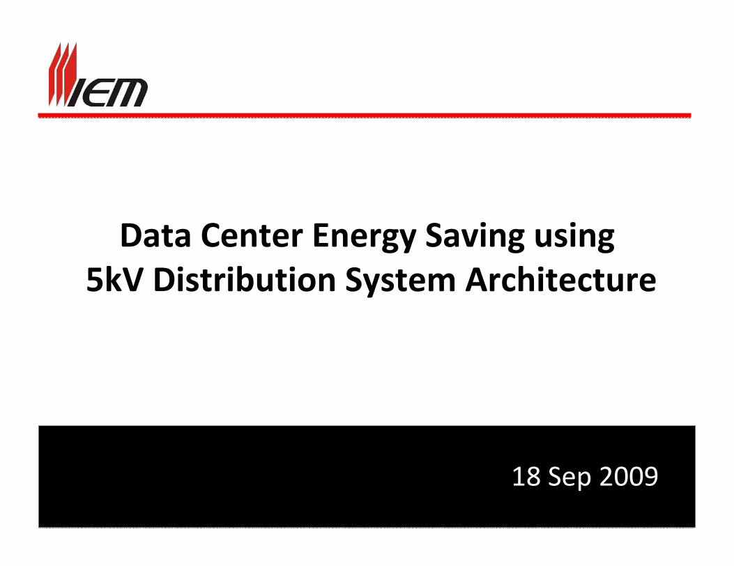
Increasing Demands• 1984 – Bank of America Data Center
– Concord, California– 250,000 Square Foot Facility– 10 Megawatt – 21 kV Service– 480V Distribution
• 2009 – Typical Local Facility– Santa Clara– 40,000 Square Feet– 12 Megawatt – 12 kV Service– 480V Distribution
In 25 Years, 16% of the Space; 120% of the Power
Why 480 Volts?• Common voltage for industrial and commercial distribution
• Wide spread usage results in readily available devices/components in equipment/distribution
• Allows easy integration of conventional static UPS systems
• Allows for easy conversion to server utilization voltage – generally 120 VAC
The Beginning
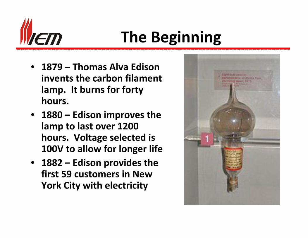
• 1879 – Thomas Alva Edison invents the carbon filament lamp. It burns for forty hours.
• 1880 – Edison improves the lamp to last over 1200 hours. Voltage selected is 100V to allow for longer life
• 1882 – Edison provides the first 59 customers in New York City with electricity
New York City Distribution 1889
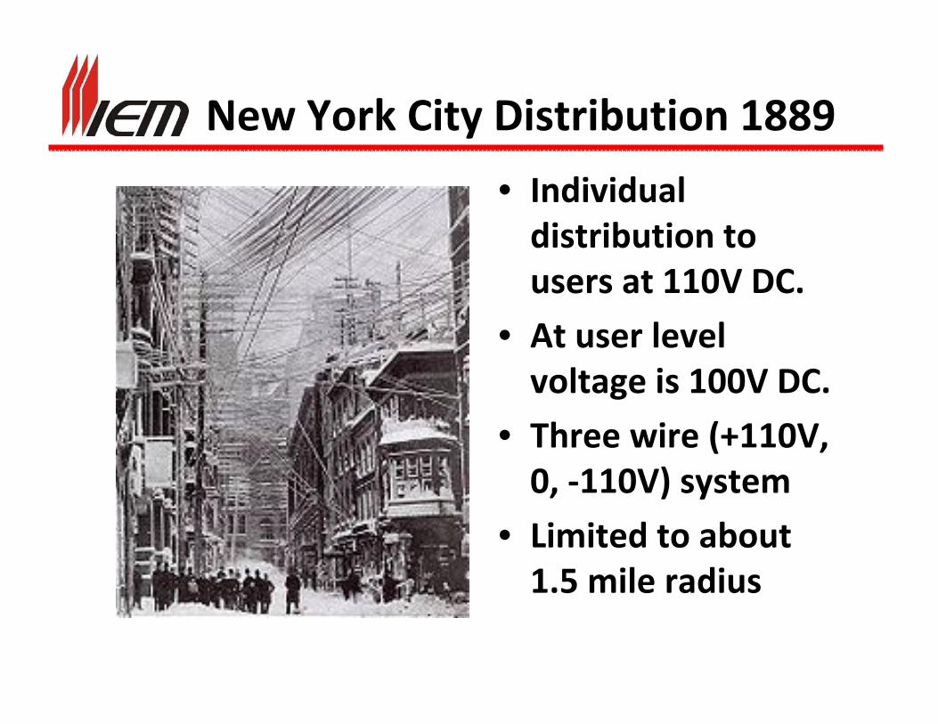
• Individual distribution to users at 110V DC.
• At user level voltage is 100V DC.
• Three wire (+110V, 0, ‐110V) system
• Limited to about 1.5 mile radius

The Rival System – AC
• George Westinghouse; “ZBD” Team, Nikola Tesla • First system in Great Barrington, Massachusetts in 1886
• At user level voltage is 100V AC.• Distribution Voltage is 3000V AC
(ZBD team was Hungarians Károly Zipernowsky, Ottó Bláthy, Miksa Déri)

War of the Currents
• Battle between DC (Edison) and AC (Westinghouse/Tesla) over which system is better.
• Harold Brown writes: “The only excuse for the use of the fatal alternating current is that it saves the company operating it from spending a larger sum of money for the heavier copper wires which are required by the safe incandescent [DC] systems. That is, the public must submit to constant danger from sudden death, in order that a corporation may pay a little larger dividend.”
Lessons to be Learned
• Maintaining status quo is generally in the best (commercial) interests of the market leaders
• Better methods often require new technology
• Consideration of methods already used elsewhere may lead to better methods for the local market
• Safety is always a consideration – and it even sometimes can be a selling feature
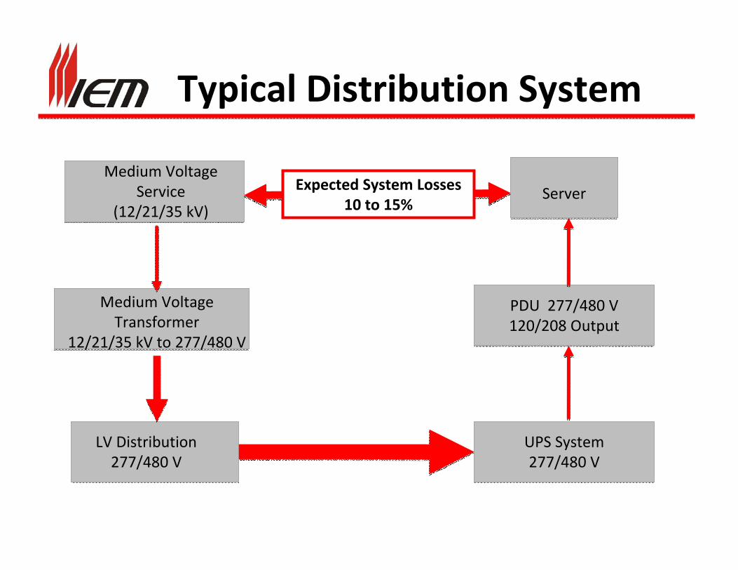
Typical Distribution System
Medium Voltage Service
(12/21/35 kV)
Medium Voltage Transformer
12/21/35 kV to 277/480 V
LV Distribution 277/480 V
UPS System277/480 V
PDU 277/480 V120/208 Output
ServerExpected System Losses10 to 15%
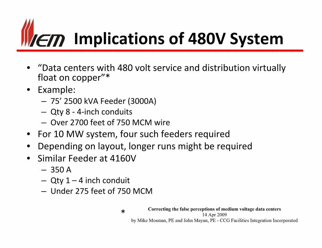
Implications of 480V System
• “Data centers with 480 volt service and distribution virtually float on copper”*
• Example:– 75’ 2500 kVA Feeder (3000A)– Qty 8 ‐ 4‐inch conduits– Over 2700 feet of 750 MCM wire
• For 10 MW system, four such feeders required• Depending on layout, longer runs might be required• Similar Feeder at 4160V
– 350 A– Qty 1 – 4 inch conduit– Under 275 feet of 750 MCM
*
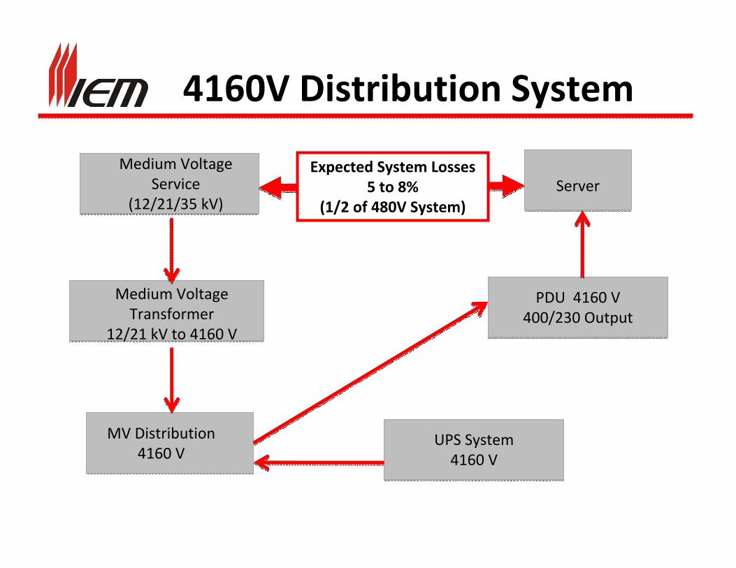
4160V Distribution System
Medium Voltage Service
(12/21/35 kV)
Medium Voltage Transformer
12/21 kV to 4160 V
MV Distribution 4160 V
UPS System4160 V
PDU 4160 V400/230 Output
ServerExpected System Losses
5 to 8% (1/2 of 480V System)

General Held Assumptions
• Medium Voltage Equipment is expensive; more than equivalent LV equipment
• Medium Voltage Equipment is much larger than equivalent LV equipment
• Medium Voltage Equipment requires more maintenance and is less reliable than LV Equipment
• Medium Voltage Equipment is not as safe as LV Equipment
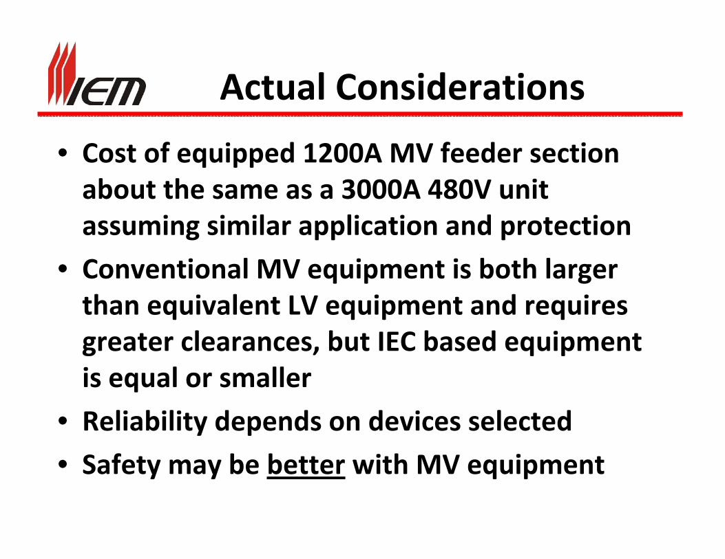
Actual Considerations
• Cost of equipped 1200A MV feeder section about the same as a 3000A 480V unit assuming similar application and protection
• Conventional MV equipment is both larger than equivalent LV equipment and requires greater clearances, but IEC based equipment is equal or smaller
• Reliability depends on devices selected
• Safety may be better with MV equipment
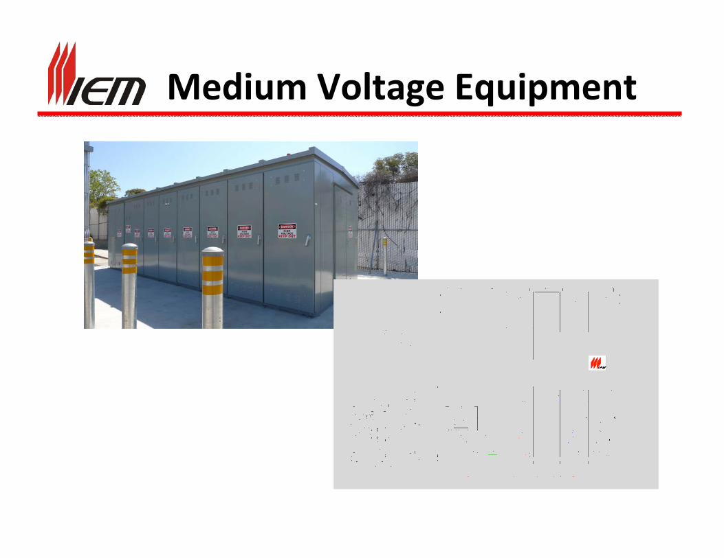
Medium Voltage Equipment

IEC Switchgear
Typical of most European builders.
About 55 to 60” Deep X 24 to 30” Wide(Compares to 85 to 96” Deep x 36” Wide ANSI Equivalent
Available with Conventional Vacuum or SF6 Breakers and Magnetically Actuated Vacuum Breakers
IEC MV Equipment Issues
• Not designed to meet US UL and ANSI standards – most significant issue is bus insulation and isolation
• Designs require the use of bar type CTs limiting number of CTs for a given breaker
• Wiring techniques differ between US and IEC –cable access in IEC generally requires disassembly.
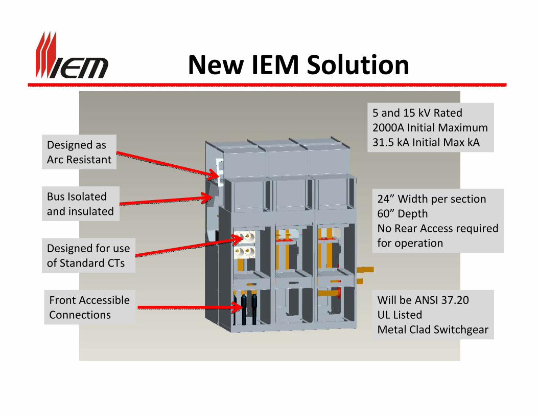
New IEM Solution
Front Accessible Connections
Designed for useof Standard CTs
Bus Isolated and insulated
Designed asArc Resistant
Will be ANSI 37.20UL ListedMetal Clad Switchgear
5 and 15 kV Rated2000A Initial Maximum31.5 kA Initial Max kA
24” Width per section60” DepthNo Rear Access requiredfor operation
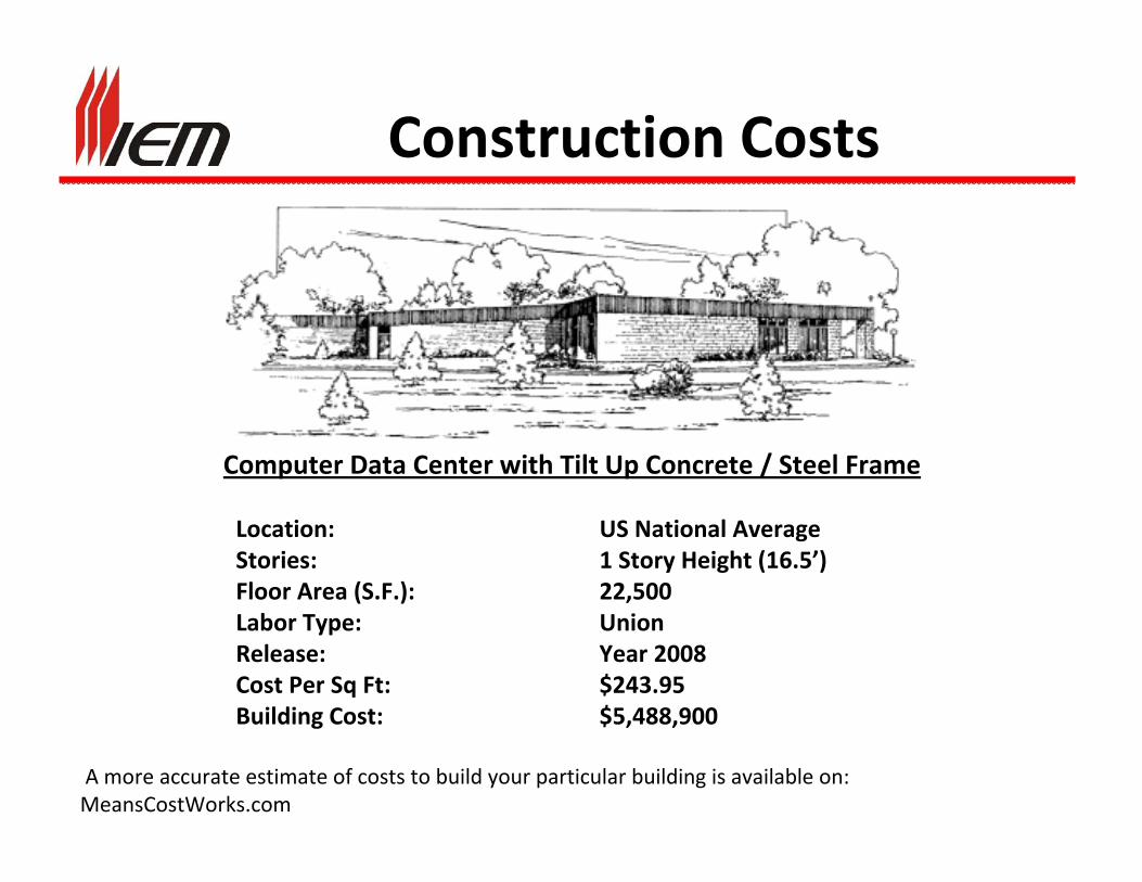
Construction Costs
Computer Data Center with Tilt Up Concrete / Steel Frame
Location: US National AverageStories: 1 Story Height (16.5’)Floor Area (S.F.): 22,500Labor Type: Union Release: Year 2008Cost Per Sq Ft: $243.95Building Cost: $5,488,900
A more accurate estimate of costs to build your particular building is available on: MeansCostWorks.com
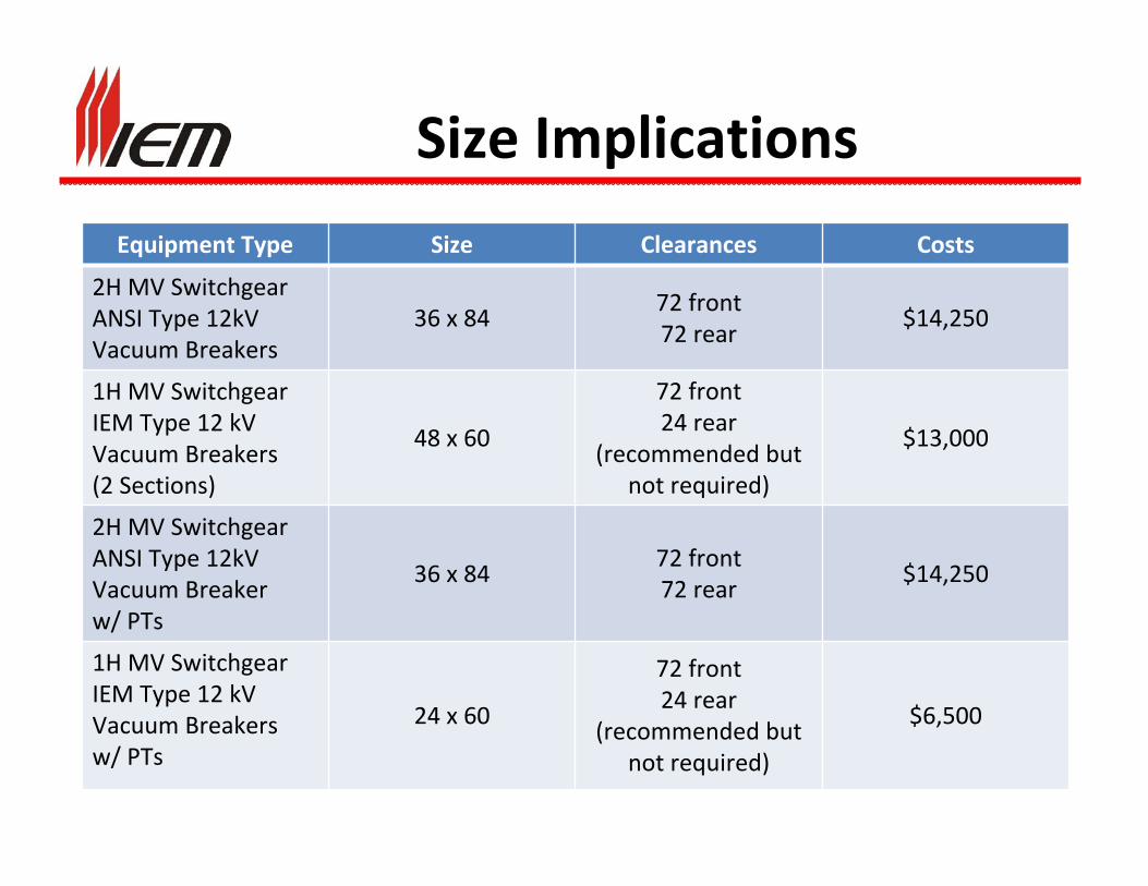
Size Implications
Equipment Type Size Clearances Costs
2H MV SwitchgearANSI Type 12kVVacuum Breakers
36 x 8472 front72 rear
$14,250
1H MV SwitchgearIEM Type 12 kVVacuum Breakers(2 Sections)
48 x 60
72 front24 rear
(recommended but not required)
$13,000
2H MV SwitchgearANSI Type 12kVVacuum Breakerw/ PTs
36 x 8472 front72 rear
$14,250
1H MV SwitchgearIEM Type 12 kVVacuum Breakersw/ PTs
24 x 60
72 front24 rear
(recommended but not required)
$6,500
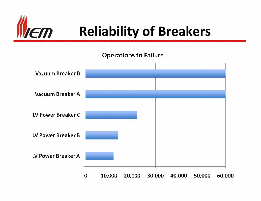
Reliability of Breakers

Safety Considerations
• Sample Case compared 4160 and 480 systems connected to identical loads and utility supply (34.5 kv – 750 MVA)
• Results:
• 480V system – Dangerous w/o Instantaneous (1.0 sec); PPE 3 w/normal instantaneous; PPE 1 w/low “safety” setting
• 4160V System – PPE 1w/normal instantaneous setting; PPE 0 w/low “safety” setting
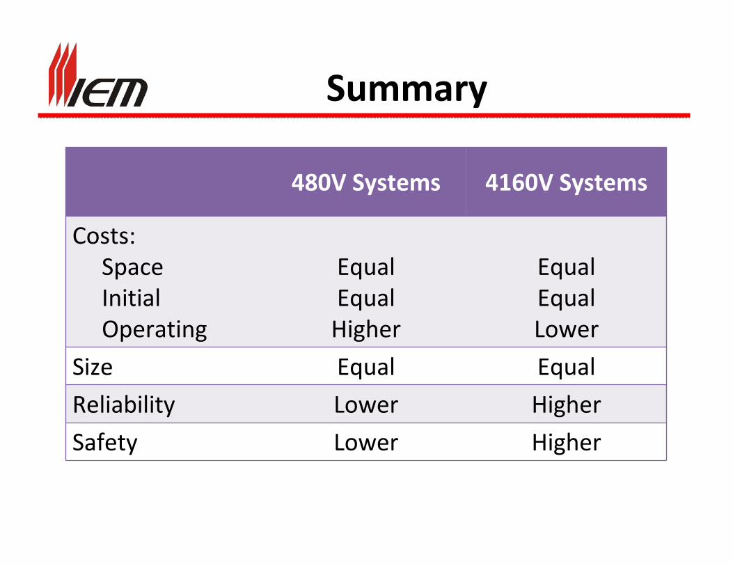
Summary
480V Systems 4160V Systems
Costs:SpaceInitialOperating
EqualEqualHigher
EqualEqualLower
Size Equal Equal
Reliability Lower Higher
Safety Lower Higher