Embed Size (px)
Citation preview

[Type text] Page 1
DATA COMMUNICATION AND NETWORKS IMPORTANT QUESTIONS WITH ANSWERS
1. Explain the types of transmission modes .
Communication between two devices can be simplex, half-duplex, or full-duplex.
Simplex
In simplex mode, the communication is unidirectional, as on a one-way street. Only one of the
two devices on a link can transmit; the other can only receive.
Keyboards and traditional monitors are examples of simplex devices. The keyboard can only
introduce input; the monitor can only accept output.
The simplex mode can use the entire capacity of the channel to send data in one direction.

[Type text] Page 2
Half-Duplex
In half-duplex mode, each station can both transmit and receive, but not at the same time.
When one device is sending, the other can only receive, and vice versa.
The half-duplex mode is like a one-lane road with traffic allowed in both directions. When cars
are traveling in one direction, cars going the other way must wait.
In a half-duplex transmission, the entire capacity of a channel is taken over by whichever of the
two devices is transmitting at the time.
Full Duplex
In full-duplex mode, both stations can transmit and receive simultaneously.
The full-duplex mode is like a two way street with traffic flowing in both directions at the same
time.
One common example of full-duplex communication is the telephone network. When two
people are communicating by a telephone line, both can talk and listen at the same time.
2. What is network topology ? Explain the different network topologies.
The term physical topology refers to the way in which a network is laid out physically: I/O or more
devices connect to a link; two or more links form a topology. There are four basic topologies possible: mesh, star, bus, and ring.
Mesh Topology
Mesh In a mesh topology, every device has a dedicated point-to-point link to every other device.
The term dedicated means that the link carries traffic only between the two devices it connects.
Node 1 must be connected to n - 1nodes, node 2 must be connected to n – 1 nodes, and finally
node n must be connected to n - 1 nodes. We need n (n - 1) physical links.

[Type text] Page 3
Advantages
The use of dedicated links guarantees that each connection can carry its own data load, thus
eliminating the traffic problems that can occur when links must be shared by multiple devices.
A mesh topology is robust. If one link becomes unusable, it does not incapacitate the entire
system.
There is the advantage of privacy or security. When every message travels along a dedicated
line, only the intended recipient sees it.
Point-to-point links make fault identification and fault isolation easy.
Disadvantages
Amount of cabling and the number of I/O ports required.
The sheer bulk of the wiring can be greater than the available space (in walls, ceilings, or floors)
can accommodate.
The hardware required to connect each link (I/O ports and cable) can be prohibitively expensive.
Star Topology
In a star topology, each device has a dedicated point-to-point link only to a central controller,
usually called a hub.
The devices are not directly linked to one another. Unlike a mesh topology, a star topology does
not allow direct traffic between devices.
The controller acts as an exchange: If one device wants to send data to another, it sends the
data to the controller, which then relays the data to the other connected device.

[Type text] Page 4
Advantages
A star topology is less expensive than a mesh topology.
In a star, each device needs only one link and one I/O port to connect it to any number
of others. This factor also makes it easy to install and reconfigure.
Far less cabling needs to be housed, and additions, moves, and deletions involve only one
connection: between that device and the hub.
Other advantages include robustness. If one link fails, only that link is affected. All other links
remain active.
Disadvantages
The dependency of the whole topology bon one single point, the hub. If the hub goes down, the
whole system is dead.
Although a star requires far less cable than a mesh, each node must be linked to a central hub.
Bus Topology
The preceding examples all describe point-to-point connections. A bus topology, on the other hand, is
multipoint. One long cable acts as a backbone to link all the devices in a network.

[Type text] Page 5
Advantages
Bus topology includes ease of installation.
A bus uses less cabling than mesh or star topologies.
Disadvantages
Difficult reconnection and fault isolation.
A fault or break in the bus cable stops all transmission, even between devices on the same side
of the problem.
Ring topology
Ring Topology In a ring topology, each device has a dedicated point-to-point connection with only the
two devices on either side of it. A signal is passed along the ring in one direction, from device to device,
until it reaches its destination.
Advantages
A ring is relatively easy to install and
reconfigure. Fault isolation is simplified.
Disadvantages
Unidirectional traffic can be a disadvantage.
In a simple ring, a break in the ring (such as a disabled station) can disable the entire network.

[Type text] Page 6
Hybrid Topology
A network can be hybrid. For example, we can have a main star topology with each branch connecting
several stations in a bus topology.
3. What are the different types of networks? Explain in detail.
Today when we speak of networks, we are generally referring to two primary categories:
Local area networks (LAN) and wide-area networks (WAN).
The category into which a network falls is determined by its size.
A LAN normally covers an area less than 2 mi; a WAN can be worldwide. Networks of a size in
between are normally referred to as metropolitan area networks and span tens of miles.
A local area network (LAN) is usually privately owned and links the devices in a single office, building, or
campus. LANs are designed to allow resources to be shared between personal computers or
workstations. The resources to be shared can include hardware (e.g., a printer), software (e.g., an
application program), or data. A common example of a LAN, found in many business environments, links
a workgroup of task-related computers, for example, engineering workstations or accounting PCs. A wide area network (WAN) provides long-distance transmission of data, image, audio, and video
information over large geographic areas that may comprise a country, a continent, or even the whole
world.
A metropolitan area network (MAN) is a network with a size between a LAN and a WAN. It normally covers the area inside a town or a city. It is designed for customers who need a high-speed connectivity, normally to the Internet, and have endpoints spread over a city or part of city. A good example of a MAN is the part of the telephone company network that can provide a high-speed DSL line to the customer.
[Type text] Page 7
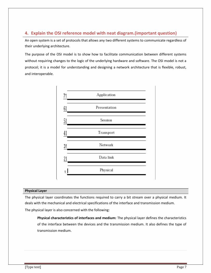
4. Explain the OSI reference model with neat diagram.(important question)
An open system is a set of protocols that allows any two different systems to communicate regardless of
their underlying architecture.
The purpose of the OSI model is to show how to facilitate communication between different systems
without requiring changes to the logic of the underlying hardware and software. The OSI model is not a
protocol; it is a model for understanding and designing a network architecture that is flexible, robust,
and interoperable.
Physical Layer
The physical layer coordinates the functions required to carry a bit stream over a physical medium. It
deals with the mechanical and electrical specifications of the interface and transmission medium.
The physical layer is also concerned with the following:
Physical characteristics of interfaces and medium: The physical layer defines the characteristics
of the interface between the devices and the transmission medium. It also defines the type of
transmission medium.

[Type text] Page 8
Representation of bits: The physical layer data consists of a stream of bits (sequence of Os or
1s) with no interpretation. To be transmitted, bits must be encoded into signals--electrical or
optical. The physical layer defines the type of encoding (how Os and I s are changed to signals).
Data rate: The transmission rate-the number of bits sent each second-is also defined by the
physical layer. In other words, the physical layer defines the duration of a bit, which is how long
it lasts.
Synchronization of bits: The sender and receiver not only must use the same bit rate but also
must be synchronized at the bit level. In other words, the sender and the receiver clocks must
be synchronized.
Line configuration: The physical layer is concerned with the connection of devices to the media.
In a point-to-point configuration, two devices are connected through a dedicated link. In a
multipoint configuration, a link is shared among several devices.
Physical topology: The physical topology defines how devices are connected to make a network.
Devices can be connected by using a mesh topology (every device is connected to every other
device), a star topology (devices are connected through a central device), a ring topology (each
device is connected to the next, forming a ring), a bus topology (every device is on a common
link), or a hybrid topology (this is a combination of two or more topologies).
Transmission mode: The physical layer also defines the direction of transmission between two
devices: simplex, half-duplex, or full-duplex. In simplex mode, only one device can send; the
other can only receive. The simplex mode is a one-way communication. In the half-duplex mode,
two devices can send and receive, but not at the same time. In a full-duplex (or simply duplex)
mode, two devices can send and receive at the same time.
Data Link Layer
The data link layer transforms the physical layer, a raw transmission facility, to a reliable link. It makes
the physical layer appear error-free to the upper layer (network layer). Other responsibilities of the data link layer include the following:
Framing: The data link layer divides the stream of bits received from the network layer into
manageable data units called frames.
Physical addressing: If frames are to be distributed to different systems on the network, the
data link layer adds a header to the frame to define the sender and/or receiver of the frame. If

[Type text] Page 9
the frame is intended for a system outside the sender's network, the receiver address is the
address of the device that connects the network to the next one.
Flow control: If the rate at which the data are absorbed by the receiver is less than the rate at
which data are produced in the sender, the data link layer imposes a flow control mechanism to
avoid overwhelming the receiver.
Error control: The data link layer adds reliability to the physical layer by adding mechanisms to
detect and retransmit damaged or lost frames. It also uses a mechanism to recognize duplicate
frames. Error control is normally achieved through a trailer added to the end of the frame.
Access control: When two or more devices are connected to the same link, data link layer
protocols are necessary to determine which device has control over the link at any given time.
Network Layer
The network layer is responsible for the source-to-destination delivery of a packet, possibly across
multiple networks (links). Whereas the data link layer oversees the delivery of the packet between two
systems on the same network (links), the network layer ensures that each packet gets from its point of
origin to its final destination. Other responsibilities of the network layer include the following:
Logical addressing. The physical addressing implemented by the data link layer handles the
addressing problem locally. If a packet passes the network boundary, we need another
addressing system to help distinguish the source and destination systems. The network layer
adds a header to the packet coming from the upper layer that, among other things, includes the
logical addresses of the sender and receiver. We discuss logical addresses later in this chapter.
Routing. When independent networks or links are connected to create internetworks (network
of networks) or a large network, the connecting devices (called routers or switches) route or
switch the packets to their final destination. One of the functions of the network layer is to
provide this mechanism. Transport Layer The transport layer is responsible for process-to-process delivery of the entire message. A process is an
application program running on a host. Whereas the network layer oversees source-to-destination
delivery of individual packets, it does not recognize any relationship between those packets. Other responsibilities of the transport layer include the following:
Service-point addressing: Computers often run several programs at the same time. For this
reason, source-to-destination delivery means delivery not only from one computer to the next

[Type text] Page 10
but also from a specific process (running program) on one computer to a specific process
(running program) on the other. The transport layer header must therefore include a type of
address called a service-point address (or port address). The network layer gets each packet to
the correct computer; the transport layer gets the entire message to the correct process on that
computer.
Segmentation and reassembly: A message is divided into transmittable segments, with each
segment containing a sequence number. These numbers enable the transport layer to
reassemble the message correctly upon arriving at the destination and to identify and replace
packets that were lost in transmission.
Connection control: The transport layer can be either connectionless or connection oriented.
A connectionless transport layer treats each segment as an independent packet and delivers it
to the transport layer at the destination machine. A connection oriented transport layer makes a
connection with the transport layer at the destination machine first before delivering the
packets. After all the data are transferred, the connection is terminated.
Flow control: Like the data link layer, the transport layer is responsible for flow control.
However, flow control at this layer is performed end to end rather than across a single link.
Error control: Like the data link layer, the transport layer is responsible for error control.
However, error control at this layer is performed process-to process rather than across a single
link. The sending transport layer makes sure that the entire message arrives at the receiving
transport layer without error (damage, loss, or duplication). Error correction is usually achieved
through retransmission.
Session Layer
The services provided by the first three layers (physical, data link, and network) are not sufficient for
some processes. The session layer is the network dialog controller. It establishes, maintains, and
synchronizes the interaction among communicating systems. The session layer is responsible for dialog
control and synchronization. Specific responsibilities of the session layer include the following:
Dialog control: The session layer allows two systems to enter into a dialog. It allows the
communication between two processes to take place in either half duplex (one way at a time) or
full-duplex (two ways at a time) mode.
Synchronization: The session layer allows a process to add checkpoints, or synchronization
points, to a stream of data. For example, if a system is sending a file of 2000 pages, it is
advisable to insert checkpoints after every 100 pages to ensure that each 100-page unit is

[Type text] Page 11
received and acknowledged independently. In this case, if a crash happens during the
transmission of page 523, the only pages that need to be resent after system recovery are pages
501 to 523. Pages previous to 501 need not be resent.
Presentation Layer The presentation layer is concerned with the syntax and semantics of the information exchanged
between two systems.
Specific responsibilities of the presentation layer include the following:
Translation: The processes (running programs) in two systems are usually exchanging
information in the form of character strings, numbers, and so on. The information must be
changed to bit streams before being transmitted. Because different computers use different
encoding systems, the presentation layer is responsible for interoperability between these
different encoding methods. The presentation layer at the sender changes the information from
its sender-dependent format into a common format. The presentation layer at the receiving
machine changes the common format into its receiver-dependent format.
Encryption: To carry sensitive information, a system must be able to ensure privacy. Encryption
means that the sender transforms the original information another form and sends the resulting
message out over the network. Decryption reverses the original process to transform the
message back to its original form.
Compression: Data compression reduces the number of bits contained in the information. Data
compression becomes particularly important in the transmission of multimedia such as text,
audio, and video.
Application Layer
The application layer enables the user, whether human or software, to access the network. It provides
user interfaces and support for services such as electronic mail, remote file access and transfer, shared
database management, and other types of distributed information services.
Bit Rate
Most digital signals are non periodic, and thus period and frequency are not appropriate
characteristics. Another term-bit rate is used to describe digital signals.
The bit rate is the number of bits sent in 1s, expressed in bits per second (bps).

[Type text] Page 12
5.Explain the tcp/ip reference model with neat diagram (important question)
TCP/IP means Transmission Control Protocol and Internet Protocol. It is the network model used in the current Internet architecture as well. Protocols are set of rules which govern every possible communication over a network. These protocols describe the movement of data between the source and destination or the internet.These protocols offer simple naming and addressing schemes.
TCP/IP that is Transmission Control Protocol and Internet Protocol was developed by Department of Defence Project Research Agency (ARPA, later DARPA) as a part of a research project of network interconnection to connect remote machines.The features that stood out during the research, which led to making the TCP/IP reference model were:
• Support for a flexible architecture. Adding more machines to a network was easy.
• The overall idea was to allow one application on one computer to talk to(send data packets) another application running on different computer.

[Type text] Page 13
Host-to-network layer
• Lowest layer of the all. • Protocol is used to connect to the host, so that the packets can be
sent over it. • Varies from host to host and network to network.
It is equivalent to the combination of physical and datalink layer. Internet layer
• Selection of a packet switching network which is based on a connectionless internetwork layer is called a internet layer.
• It is the layer which holds the whole architecture together. • It helps the packet to travel independently to the destination. • Order in which packets are received is different from the way they
are sent. • IP (Internet Protocol) is used in this layer.
Transport layer
• It decides if data transmission should be on parallel path or single path.
• Functions such as multiplexing, segmenting or splitting on the data is done by transport layer.
• The applications can read and write to the transport layer. • Transport layer adds header information to the data. • Transport layer breaks the message (data) into small units so that
they are handled more efficiently by the network layer. Transport layer also arrange the packets to be sent, in sequence. Application layer
• TELNET is a two-way communication protocol which allows connecting to a remote machine and run applications on it.

[Type text] Page 14
• FTP(File Transfer Protocol) is a protocol, that allows File transfer amongst computer users connected over a network. It is reliable, simple and efficient.
• SMTP(Simple Mail Transport Protocol) is a protocol, which is used to transport electronic mail between a source and destination, directed via a route.
• DNS(Domain Name Server) The Domain Name System (DNS) is a hierarchical decentralized naming system for computers, services, or other resources connected to the Internet or a private network
6.What is Nyquist signaling rate for noiseless channel ?
For a noiseless channel, the Nyquist bit rate formula defines the theoretical maximum bit rate
BitRate = 2 x bandwidth x l0g2 L
In this formula, bandwidth is the bandwidth of the channel, L is the number of signal levels used to
represent data, and Bit Rate is the bit rate in bits per second. Example:
Consider a noiseless channel with a bandwidth of 3000 Hz transmitting a signal with two signal levels.
The maximum bit rate can be calculated as
BitRate =2 x 3000 x log2 2 =6000 bps
7. What is Shannon capacity for Noisy Channel ?
In reality, we cannot have a noiseless channel; the channel is always noisy. In 1944, Claude Shannon
introduced a formula, called the Shannon capacity, to determine the theoretical highest data rate for a
noisy channel:
Capacity =bandwidth X log2 (1 +SNR)
In this formula, bandwidth is the bandwidth of the channel, SNR is the signal-to-noise ratio, and capacity
is the capacity of the channel in bits per second. Note that in the Shannon formula there is no indication
of the signal level, which means that no matter how many levels we have, we cannot achieve a data rate
higher than the capacity of the channel. In other words, the formula defines a characteristic of the
channel, not the method of transmission.

[Type text] Page 15
8.What is Attenuation ?
Attenuation means a loss of energy. When a signal, simple or composite, travels through a medium, it
loses some of its energy in overcoming the resistance of the medium. That is why a wire carrying electric
signals gets warm, if not hot, after a while. Some of the electrical energy in the signal is converted to
heat. To compensate for this loss, amplifiers are used to amplify the signal.
Decibel
To show that a signal has lost or gained strength, engineers use the unit of the decibel.
The decibel (dB) measures the relative strengths of two signals or one signal at two different
points.
Note that the decibel is negative if a signal is attenuated and positive if a signal is amplified. Variables PI and P2 are the powers of a signal at points 1 and 2, respectively.
9. Explain AM , FM and PM
Digital-to-analog conversion is the process of changing one of the characteristics of an analog signal
based on the information in digital data.
[Type text] Page 16
Analog-to-analog conversion, or analog modulation, is the representation of analog information
by an analog signal. One may ask why we need to modulate an analog signal; it is already
analog. Modulation is needed if the medium is band pass in nature or if only a band pass
channel is available to us. An example is radio. The government assigns a narrow bandwidth to
each radio station. The analog signal produced by each station is a low-pass signal, all in the
same range. To be able to listen to different stations, the low-pass signals need to be shifted,
each to a different range.
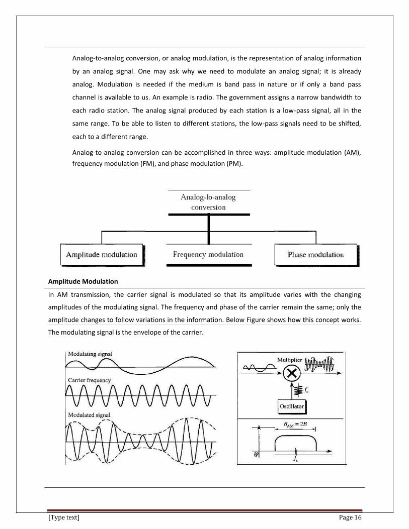
Analog-to-analog conversion can be accomplished in three ways: amplitude modulation (AM),
frequency modulation (FM), and phase modulation (PM).
Amplitude Modulation
In AM transmission, the carrier signal is modulated so that its amplitude varies with the changing
amplitudes of the modulating signal. The frequency and phase of the carrier remain the same; only the
amplitude changes to follow variations in the information. Below Figure shows how this concept works.
The modulating signal is the envelope of the carrier.

[Type text] Page 17
Frequency Modulation
In FM transmission, the frequency of the carrier signal is modulated to follow the changing voltage level
(amplitude) of the modulating signal. The peak amplitude and phase of the carrier signal remain
constant, but as the amplitude of the information signal changes, the frequency of the carrier changes
correspondingly.
Phase Modulation
In PM transmission, the phase of the carrier signal is modulated to follow the changing voltage level
(amplitude) of the modulating signal. The peak amplitude and frequency of the carrier signal remain
constant, but as the amplitude of the information signal changes, the phase of the carrier changes
correspondingly. In FM, the instantaneous change in the carrier frequency is proportional to the
amplitude of the modulating signal; in PM the instantaneous change in the carrier frequency is
proportional to the derivative of the amplitude of the modulating signal.

[Type text] Page 18
10. Explain the concept of MODEM.
• Modem is abbreviation for Modulator – Demodulator. Modems are used for data transfer from one computer network to another computer network through telephone lines.
• The computer network works in digital mode, while analog technology is used for carrying massages across phone lines.
• Modulator converts information from digital mode to analog mode at the transmitting end and demodulator converts the same from analog to digital at receiving end.
• The process of converting analog signals of one computer network into digital signals of another computer network so they can be processed by a receiving computer is referred to as digitizing.
Modems can be of several types and they can be categorized in a number of ways.
Categorization is usually based on the following basic modem features: • 1. Directional capacity: half duplex modem and full duplex modem. • 2. Connection to the line: 2-wire modem and 4-wire modem. • 3. Transmission mode: asynchronous modem and synchronous modem.
Categories of modem • External modem • Internal modem
Any external modem is attached to any computer has an RS-232 port. An internal modem comes as an expansion board that can be inserted into a vacant expansion slot.
Types of modem • Standard fax modem • Digital cable modem • ISDN modem • Digital subscribes line modem • Satellite modem
[Type text] Page 19
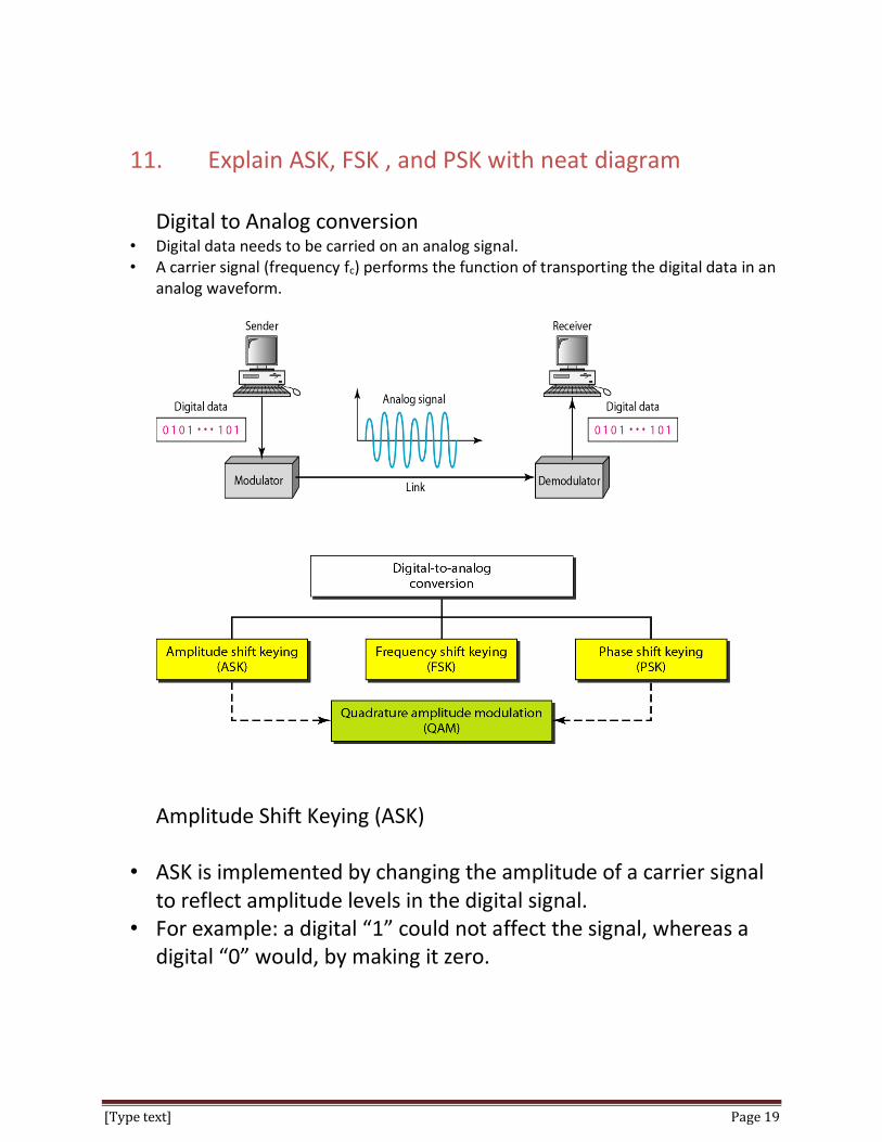
11. Explain ASK, FSK , and PSK with neat diagram Digital to Analog conversion
• Digital data needs to be carried on an analog signal. • A carrier signal (frequency fc) performs the function of transporting the digital data in an
analog waveform.
Amplitude Shift Keying (ASK)
• ASK is implemented by changing the amplitude of a carrier signal to reflect amplitude levels in the digital signal.
• For example: a digital “1” could not affect the signal, whereas a digital “0” would, by making it zero.

[Type text] Page 20
Frequency Shift Keying The two binary values are represented by two different frequencies
Phase Shift Keying
• The phase of carrier signal is shifted to represent the data. • In PSK , the phase is varied to represent binary 1 or 0.

[Type text] Page 21
12. Explain the various types of multiplexing
Whenever the bandwidth of a medium linking two devices is greater than the bandwidth needs
of the devices, the link can be shared.
Multiplexing is the set of techniques that allows the simultaneous transmission of multiple
signals across a single data link.
As data and telecommunications use increases, so does traffic. We can accommodate this
increase by continuing to add individual links each time a new channel is needed; or we can
install higher-bandwidth links and use each to carry multiple signals.
In a multiplexed system, n lines share the bandwidth of one link.
The lines on the left direct their transmission streams to a multiplexer (MUX), which combines
them into a single stream (many-to-one).
The word channel refers to the portion of a link that carries a transmission between a given pair
of lines. One link can have many (n) channels.
There are three basic multiplexing techniques: frequency-division multiplexing, wavelength-
division multiplexing, and time-division multiplexing. The first two are techniques designed for
analog signals, the third, for digital signals.

[Type text] Page 22
Frequency-Division Multiplexing (FDM)
Frequency-division multiplexing (FDM) is an analog technique that can be applied when the
bandwidth of a link (in hertz) is greater than the combined bandwidths of the signals to be
transmitted.
In FDM, signals generated by each sending device modulate different carrier frequencies. These
modulated signals are then combined into a single composite signal that can be transported by
the link.
Carrier frequencies are separated by sufficient bandwidth to accommodate the modulated
signal.
These bandwidth ranges are the channels through which the various signals travel. Channels can
be separated by strips of unused bandwidth-guard bands-to prevent signals from overlapping.
In addition, carrier frequencies must not interfere with the original data frequencies.
Multiplexing Process
Each source generates a signal of a similar frequency range. Inside the multiplexer, these similar signals
modulate different carrier frequencies f1, f2, and f3). The resulting modulated signals are then
combined into a single composite signal that is sent out over a media link that has enough bandwidth to
accommodate it.
Demultiplexing Process

[Type text] Page 23
The de-multiplexer uses a series of filters to decompose the multiplexed signal into its constituent
component signals. The individual signals are then passed to a demodulator that separates them from
their carriers and passes them to the output lines.
Wavelength-Division Multiplexing (WDM)
Wavelength-division multiplexing (WDM) is designed to use the high-data-rate capability of
fiber-optic cable. The optical fiber data rate is higher than the data rate of metallic transmission
cable. Using a fiber-optic cable for one single line wastes the available bandwidth. Multiplexing
allows us to combine several lines into one.
WDM is conceptually the same as FDM, except that the multiplexing and de-multiplexing involve
optical signals transmitted through fiber-optic channels. The idea is the same: We are combining
different signals of different frequencies. The difference is that the frequencies are very high.

[Type text] Page 24
Time-Division Multiplexing (TDM)
Time-division multiplexing (TDM) is a digital process that allows several connections to share the high
bandwidth of a link Instead of sharing a portion of the bandwidth as in FDM, time is shared. Each
connection occupies a portion of time in the link.
13. Explain the concept of SONET multiplexing . The first generation of equipment for optical fiber transmission was proprietary and no standards were
available for the interconnection of equipment from different vendors.
To meet the urgent need for standards to interconnect optical transmission system, the Synchronous
Optical Network (SONET) standards were developed in North America.
The CCIT later developed a corresponding set of standards called Synchronous Digital Hierarchy(SDH)
which was used in Europe and many other countries.
SONET/SDH is a Synchronous network. A single clock is used to handle the timing of transmissions and
equipment across the entire network.
SONET, a multiplexed transport mechanism as can be used as the carrier for broadband services,
particularly ATM and B-ISDN.
Synchronous Transport Signal
SONET defines a hierarchy of signaling levels called synchronous transport signal (STS’s).
Each STS level (STS-1 to STS-192) supports a certain data rate, specified in megabits per second.
The physical links defined to carry each level of STS are called optical carriers (OCs).
Sonet Mulitplexing
Lower rate STSs can be multiplexed to make them compatible with higher rate systems.

[Type text] Page 25
For example, three STS-1s can be combined into one STS-3s can be multiplexed into one STS-12, and so
on. The general format STS-n is made up of lower rate STSs. However, that in actual practice lower rate
STSs is interleaved.
14. Explain the Shielded twisted pair (STP) and Unshielded
twisted pair(UTP)
A transmission medium can be broadly defined as anything that can carry information from a
source to a destination.
For example, the transmission medium for two people having a dinner conversation is the air.
The air can also be used to convey the message in a smoke signal or semaphore. For a written
message, the transmission medium might be a mail carrier, a truck, or an airplane.
In telecommunications, transmission media can be divided into two broad categories: guided
and unguided. Guided media include twisted-pair cable, coaxial cable, and fiber-optic cable.
Unguided medium is free space. Below Figure shows this taxonomy.
Guided Media
Guided media, which are those that provide a conduit from one device to another, include
twisted-pair cable, coaxial cable, and fiber-optic cable.

[Type text] Page 26
A signal traveling along any of these media is directed and contained by the physical limits of the
medium. Twisted-pair and coaxial cable use metallic (copper) conductors that accept and
transport signals in the form of electric current.
Optical fiber is a cable that accepts and transports signals in the form of light.
Twisted-Pair Cable
A twisted pair consists of two conductors (normally copper), each with its own plastic insulation,
twisted together, as shown in below figure.
One of the wires is used to carry signals to the receiver, and the other is used only as a ground
reference. The receiver uses the difference between the two.
In addition to the signal sent by the sender on one of the wires, interference (noise) and
crosstalk may affect both wires and create unwanted signals.
Unshielded Versus Shielded Twisted-Pair Cable
The most common twisted-pair cable used in communications is referred to as unshielded
twisted-pair (UTP).
IBM has also produced a version of twisted-pair cable for its use called shielded twisted-pair
(STP).

[Type text] Page 27
STP cable has a metal foil or braided mesh covering that encases each pair of insulated
conductors. Although metal casing improves the quality of cable by preventing the penetration
of noise or crosstalk, it is bulkier and more expensive.
Applications
Twisted-pair cables are used in telephone lines to provide voice and data channels.
The local loop-the line that connects subscribers to the central telephone office – commonly
consists of unshielded twisted-pair cables.
The DSL lines that are used by the telephone companies to provide high-data-rate connections
also use the high-bandwidth capability of unshielded twisted-pair cables.
15. Explain the coaxial cable in detail

[Type text] Page 28
• A coaxial cable is a type of shielded and insulated copper cable that is used in computer
networks and to deliver cable TV services to end users. • The outer conductor acts as a shield against noise and crosstalk. The outer conductor is
enclosed and whole cable is protected by a plastic cover. • The distance between the outer conductor and inner conductor plus the type of material used
for insulating the inner conductor determine the cable properties. • The most standard coaxial cable connector BNC (Bayone – Neill concelman ) connector. • BNC connector is used to connect to the end of the cable to a device(Such as TV). • Used in cable TV networks • Used in analog telephone networks • Used in Ethernet LAN.
16. Explain fiber optic in detail
• Optical fiber transmission systems were introduced in 1970. It offered greater advantages over copper based digital transmission systems.
• a thin flexible fiber with a glass core through which light signals can be sent.
• Fiber optic cable has the ability to transmit signals over much longer distances.
• Optical fiber are immune to interference and cross talk

[Type text] Page 29
Propogation mode
• A fiber optic cable is made of center glass core surrounded by a concentric layer of glass(cladding).
• The information is transmitted thru the glass core in the form of light. • An important characteristic of fiber optic is refraction. Refraction is the characteristic of a
material to either pass or reflect the light. When a light passes thru the medium, it bends as it passes from one medium to another.
• Wave length Division Multiplexing is an effective approach to explore the bandwidth that is available in optical fiber. In WDM multiple wave length are used to carry several information simultaneously over the same fiber.
Advantages

[Type text] Page 30
• It supports higher bandwidth • It runs greater distance. • Electromagnetic noise cannot affect fiber optic cables • Usage of glass makes more resistant than copper
Disadvantages
• Installation and maintenance is difficult. • Unidirectional light propagation. Two fibers are used for bidirectional propagation. • The cable and the interfaces are more expensive.
17. Write short notes on unguided media
Unguided media transport electromagnetic waves without using a physical conductor. This type
of communication is often referred to as wireless communication. Signals are normally
broadcast through free space and thus are available to anyone who has a device capable of
receiving them.
Unguided signals can travel from the source to destination in several ways: ground propagation,
sky propagation, and line-of-sight propagation, as shown in Figure.
in ground propagation, radio waves travel through the lowest portion of the atmosphere,
hugging the earth.
In sky propagation, higher-frequency radio waves radiate upward into the ionosphere (the layer
of atmosphere where particles exist as ions) where they are reflected back to earth.
In line-or-sight propagation, very high-frequency signals are transmitted in straight lines directly
from antenna to antenna.
We can divide wireless transmission into three broad groups: radio waves, microwaves, and
infrared waves.
Radio Waves

[Type text] Page 31
Although there is no clear-cut demarcation between radio waves and microwaves,
electromagnetic waves ranging in frequencies between 3 kHz and 1 GHz are normally called
radio waves; waves ranging in frequencies between 1 and 300 GHz are called microwaves.
Radio waves, for the most part, are omni-directional. When an antenna transmits radio waves,
they are propagated in all directions. This means that the sending and receiving antennas do not
have to be aligned.
The omni-directional property has a disadvantage, too. The radio waves transmitted by one
antenna are susceptible to interference by another antenna that may send signals using the
same frequency or band.
Radio waves, particularly those waves that propagate in the sky mode, can travel long distances.
This makes radio waves a good candidate for long-distance broadcasting such as AM radio. Omni directional Antenna
Radio waves use omni directional antennas that send out signals in all directions. Based on the
wavelength, strength, and the purpose of transmission, we can have several types of antennas. Applications
The omni directional characteristics of radio waves make them useful for multicasting, in which there
is one sender but many receivers. AM and FM radio, television, maritime radio, cordless phones, and
paging are examples of multicasting.
Microwaves
Electromagnetic waves having frequencies between I and 300 GHz are called microwaves.
Microwaves are unidirectional.

[Type text] Page 32
When an antenna transmits microwave waves, they can be narrowly focused. This means that
the sending and receiving antennas need to be aligned. The unidirectional property has an
obvious advantage. A pair of antennas can be aligned without interfering with another pair of
aligned antennas.
The following describes some characteristics of microwave propagation:
Microwave propagation is line-of-sight. Since the towers with the mounted antennas
need to be in direct sight of each other, towers that are far apart need to be very tall.
The curvatures of the earth as well as other blocking obstacles do not allow two short
towers to communicate by using microwaves. Repeaters are often needed for long
distance communication.
Very high-frequency microwaves cannot penetrate walls. This characteristic can be a
disadvantage if receivers are inside buildings.
The microwave band is relatively wide, almost 299 GHz. Therefore wider sub bands can
be assigned, and a high data rate is possible.
Use of certain portions of the band requires permission from authorities.
Unidirectional Antenna
Microwaves need unidirectional antennas that send out signals in one direction. Two types of antennas
are used for microwave communications: the parabolic dish and the home.
Applications
Microwaves, due to their unidirectional properties, are very useful when unicast (one-to-one)
communication is needed between the sender and the receiver.
They are used in cellular phones, satellite networks and wireless LANs.

[Type text] Page 33
Infrared
Infrared waves, with frequencies from 300 GHz to 400 THz (wavelengths from 1 mm to 770 nm), can be
used for short-range communication. Infrared waves, having high frequencies, cannot penetrate walls.
Applications
The infrared band, almost 400 THz, has an excellent potential for data transmission. Such a wide
bandwidth can be used to transmit digital data with a very high data rate.
18. Write short notes on circuit switching , packet switching and message switching
A switched network consists of a series of interlinked nodes, called switches. Switches are devices
capable of creating temporary connections between two or more devices linked to the switch. In a
switched network, some of these nodes are connected to the end systems.
Traditionally, three methods of switching have been important: circuit switching, packet switching, and
message switching. The first two are commonly used today. The third has been phased out in general
communications but still has networking applications. We can then divide today's networks into three
broad categories: circuit-switched networks, packet-switched networks, and message-switched. Packet-
switched networks can further be divided into two subcategories-virtual-circuit networks and datagram
networks as shown in Figure.
Circuit switching and Telephone Network
A circuit-switched network consists of a set of switches connected by physical links. A
connection between two stations is a dedicated path made of one or more links.

[Type text] Page 34
However, each connection uses only one dedicated channel on each link. Each link is normally
divided into n channels by using FDM or TDM.
circuit switching takes place at the physical layer.
Before starting communication, the stations must make a reservation for the resources to be
used during the communication. These resources, such as channels (bandwidth in FDM and time
slots in TDM), switch buffers, switch processing time, and switch input/output ports, must
remain dedicated during the entire duration of data transfer until the teardown phase.
Data transferred between the two stations are not packetized (physical layer transfer of the
signal). The data are a continuous flow sent by the source station and received by the
destination station, although there may be periods of silence.
There is no addressing involved during data transfer. The switches route the data based on their
occupied band (FDM) or time slot (TDM). Of course, there is end-to-end addressing used during
the setup phase.
Three Phases
The actual communication in a circuit-switched network requires three phases: connection setup, data
transfer, and connection teardown.
setup Phase
Before the two parties (or multiple parties in a conference call) can communicate, a dedicated circuit
(combination of channels in links) needs to be established. The end systems are normally connected
through dedicated lines to the switches, so connection setup means creating dedicated channels
between the switches. Data Transfer Phase
After the establishment of the dedicated circuit (channels), the two parties can transfer data.
Teardown Phase
When one of the parties needs to disconnect, a signal is sent to each switch to release the resources.
Circuit-Switched Technology in Telephone Networks
The telephone companies have previously chosen the circuit switched approach to switching in the
physical layer; today the tendency is moving toward other switching techniques. For example, the
telephone number is used as the global address, and a signaling system (called SS7) is used for the setup
and teardown phases.
[Type text] Page 35
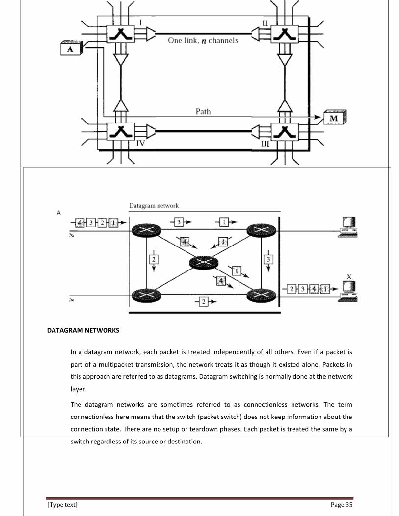
DATAGRAM NETWORKS
In a datagram network, each packet is treated independently of all others. Even if a packet is
part of a multipacket transmission, the network treats it as though it existed alone. Packets in
this approach are referred to as datagrams. Datagram switching is normally done at the network
layer.
The datagram networks are sometimes referred to as connectionless networks. The term
connectionless here means that the switch (packet switch) does not keep information about the
connection state. There are no setup or teardown phases. Each packet is treated the same by a
switch regardless of its source or destination.

[Type text] Page 36
Routing Table
If there are no setup or teardown phases, how are the packets routed to their destinations in a
datagram network? In this type of network, each switch (or packet switch) has a routing table which is
based on the destination address. The routing tables are dynamic and are updated periodically. The
destination addresses and the corresponding forwarding output ports are recorded in the tables. This is
different from the table of a circuit switched network in which each entry is created when the setup
phase is completed and deleted when the teardown phase is over.
Routing Table]
Destination Address
Every packet in a datagram network carries a header that contains, among other information, the
destination address of the packet. When the switch receives the packet, this destination address is
examined; the routing table is consulted to find the corresponding port through which the packet should
be forwarded. This address, unlike the address in a virtual-circuit-switched network, remains the same
during the entire journey of the packet. Efficiency
The efficiency of a datagram network is better than that of a circuit-switched network; resources are
allocated only when there are packets to be transferred. If a source sends a packet and there is a delay
of a few minutes before another packet can be sent, the resources can be reallocated during these
minutes for other packets from other sources. Delay
There may be greater delay in a datagram network than in a virtual-circuit network. Although there are
no setup and teardown phases, each packet may experience a wait at a switch before it is forwarded.

[Type text] Page 37
Packet Switching
Packet switching is a digital networking communications method that groups all transmitted data –
regardless of content, type, or structure – into suitably sized blocks, called packets. Packet switching
features delivery of variable-bit-rate data streams (sequences of packets) over a shared network. When
traversing network adapters, switches, routers and other network nodes, packets are buffered and
queued, resulting in variable delay and throughput depending on the traffic load in the network.
Packet switching contrasts with another principal networking paradigm, circuit switching, a method
which sets up a limited number of dedicated connections of constant bit rate and constant delay
between nodes for exclusive use during the communication session. In case of traffic fees (as opposed
to flat rate), for example in cellular communication services, circuit switching is characterized by a fee
per time unit of connection time, even when no data is transferred, while packet switching is
characterized by a fee per unit of information.
Two major packet switching modes exist:
(1) Connectionless packet switching, also known as datagram switching, and (2) Connection-oriented packet switching, also known as virtual circuit switching.
In the first case each packet includes complete addressing or routing information. The packets are
routed individually, sometimes resulting in different paths and out-of-order delivery.
In the second case a connection is defined and preallocated in each involved node during a connection
phase before any packet is transferred.
[Type text] Page 38
19. What is an error ? Explain the types of errors ?
Data can be corrupted during transmission. Some applications require that errors be detected and
corrected. Types of Errors
Whenever bits flow from one point to another, they are subject to unpredictable changes because of
interference. This interference can change the shape of the signal. Errors are of two types: Single-Bit Error
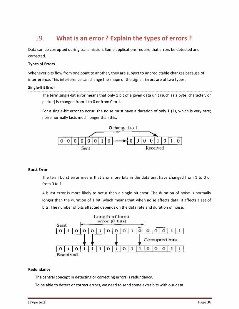
The term single-bit error means that only 1 bit of a given data unit (such as a byte, character, or
packet) is changed from 1 to 0 or from 0 to 1.
For a single-bit error to occur, the noise must have a duration of only 1 ) ls, which is very rare;
noise normally lasts much longer than this.
Burst Error
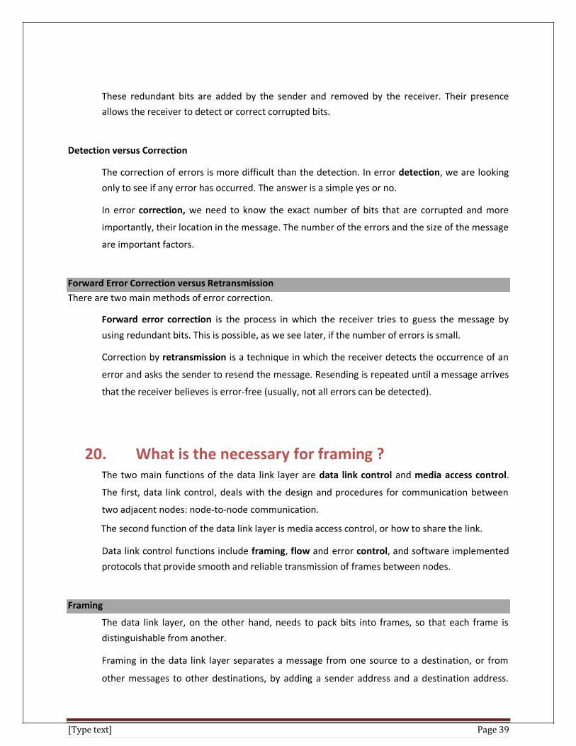
The term burst error means that 2 or more bits in the data unit have changed from 1 to 0 or
from 0 to 1.
A burst error is more likely to occur than a single-bit error. The duration of noise is normally
longer than the duration of 1 bit, which means that when noise affects data, it affects a set of
bits. The number of bits affected depends on the data rate and duration of noise.
Redundancy
The central concept in detecting or correcting errors is redundancy.
To be able to detect or correct errors, we need to send some extra bits with our data.
[Type text] Page 39
These redundant bits are added by the sender and removed by the receiver. Their presence
allows the receiver to detect or correct corrupted bits.
Detection versus Correction
The correction of errors is more difficult than the detection. In error detection, we are looking
only to see if any error has occurred. The answer is a simple yes or no.
In error correction, we need to know the exact number of bits that are corrupted and more
importantly, their location in the message. The number of the errors and the size of the message
are important factors.
Forward Error Correction versus Retransmission There are two main methods of error correction.
Forward error correction is the process in which the receiver tries to guess the message by
using redundant bits. This is possible, as we see later, if the number of errors is small.
Correction by retransmission is a technique in which the receiver detects the occurrence of an
error and asks the sender to resend the message. Resending is repeated until a message arrives
that the receiver believes is error-free (usually, not all errors can be detected).
20. What is the necessary for framing ?
The two main functions of the data link layer are data link control and media access control.
The first, data link control, deals with the design and procedures for communication between
two adjacent nodes: node-to-node communication.
The second function of the data link layer is media access control, or how to share the link.
Data link control functions include framing, flow and error control, and software implemented
protocols that provide smooth and reliable transmission of frames between nodes.
Framing
The data link layer, on the other hand, needs to pack bits into frames, so that each frame is
distinguishable from another.
Framing in the data link layer separates a message from one source to a destination, or from
other messages to other destinations, by adding a sender address and a destination address.

[Type text] Page 40
The destination address defines where the packet is to go; the sender address helps the
recipient acknowledge the receipt. Frames can be of fixed or variable size.
21. Explain the protocols in Data link layer .
Data link layer can combine framing, flow control, and error control to achieve the delivery of
data from one node to another.
We divide the discussion of protocols into those that can be used for noiseless (error-free)
channels and those that can be used for noisy (error-creating) channels.
The protocols in the first category cannot be used in real life, but they serve as a basis for
understanding the protocols of noisy channels.
Stop-and- Wait ARQ
To detect and correct corrupted frames, we need to add redundancy bits to our data frame.
When the frame arrives at the receiver site, it is checked and if it is corrupted, it is silently
discarded. The detection of errors in this protocol is manifested by the silence of the receiver.
When the receiver receives a data frame that is out of order, this means that frames were either
lost or duplicated. The corrupted and lost frames need to be resent in this protocol. If the
receiver does not respond when there is an error, how can the sender know which frame to
resend?
To remedy this problem, the sender keeps a copy of the sent frame. At the same time, it starts a
timer. If the timer expires and there is no ACK for the sent frame, the frame is resent, the copy is
held, and the timer is restarted.
Error correction in Stop-and-Wait ARQ is done by keeping a copy of the sent frame and
retransmitting of the frame when the timer expires.

[Type text] Page 41
Sequence Numbers
A frame is numbered by sequence numbers.
A field is added to the data frame to hold the sequence number of that frame.
If we decide that the field is m bits long, the sequence numbers start from 0, go to 2m - 1, and then
are repeated.
Let us consider three cases:
1. The frame arrives safe and sound at the receiver site; the receiver sends an acknowledgment. The
acknowledgment arrives at the sender site, causing the sender to send the next frame numbered x + 1. 2. The frame arrives safe and sound at the receiver site; the receiver sends an acknowledgment, but the
acknowledgment is corrupted or lost. The sender resends the frame (numbered x) after the time-out.
Note that the frame here is a duplicate. The receiver can recognize this fact because it expects frame x +
1 but frame x was received. 3. The frame is corrupted or never arrives at the receiver site; the sender resends the frame (numbered
x) after the time-out.

[Type text] Page 42
Go-Back-N ARQ
To improve the efficiency of transmission (filling the pipe), multiple frames must be in transition
while waiting for acknowledgment. In other words, we need to let more than one frame be
outstanding to keep the channel busy while the sender is waiting for acknowledgment.
The first is called Go-Back-N Automatic Repeat Request. In this protocol we can send several
frames before receiving acknowledgments; we keep a copy of these frames until the
acknowledgments arrive.
In Go-Back-N ARQ, the size of the send window must be less than 2m; the size of the receiver
window is always 1.
Sequence Numbers
Frames from a sending station are numbered sequentially. However, because we need to include the
sequence number of each frame in the header, we need to set a limit. If the header of the frame allows
m bits for the sequence number, the sequence numbers range from 0 to 2m - 1. For example, if m is 4,
the only sequence numbers are 0 through 15 inclusive. However, we can repeat the sequence. So the
sequence numbers are 0, 1, 2, 3, 4, 5, 6, 7, 8, 9, 10, 11, 12, 13, 14, 15, 0, 1, 2, 3, 4, 5, 6, 7, 8, 9, 10, 11, .......
In other words, the sequence numbers are modulo-2m. In the Go-Back-N Protocol, the sequence
numbers are modulo 2m, where m is the size of the sequence number field in bits.
Sliding Window In Go-Back-N Automatic Repeat Request, the sliding window is an abstract concept that defines the
range of sequence numbers that is the concern of the sender and receiver. In other words, the sender
and receiver need to deal with only part of the possible sequence numbers. The range which is the
concern of the sender is called the send sliding window; the range that is the concern of the receiver is
called the receive sliding window. The window at any time divides the possible sequence numbers into four regions.
The first region, from the far left to the left wall of the window, defines the sequence numbers
belonging to frames that are already acknowledged. The sender does not worry about these
frames and keeps no copies of them.
The second region defines the range of sequence numbers belonging to the frames that are sent
and have an unknown status. The sender needs to wait to find out if these frames have been
received or were lost. We call these outstanding frames.

[Type text] Page 43
The third range defines the range of sequence numbers for frames that can be sent; however,
the corresponding data packets have not yet been received from the network layer.
Finally, the fourth region defines sequence numbers that cannot be used until the window
slides.
Send Window for Go Back N ARQ
The window itself is an abstraction; three variables define its size and location at any time. We call these
variables Sf (send window, the first outstanding frame), Sn (send window, the next frame to be sent),
and Ssize (send window, size).
The variable Sf defines the sequence number of the first (oldest) outstanding frame.
The variable Sn holds the sequence number that will be assigned to the next frame to be
sent. Finally, the variable Ssize defines the size of the window, which is fixed in our protocol.
[Type text] Page 44
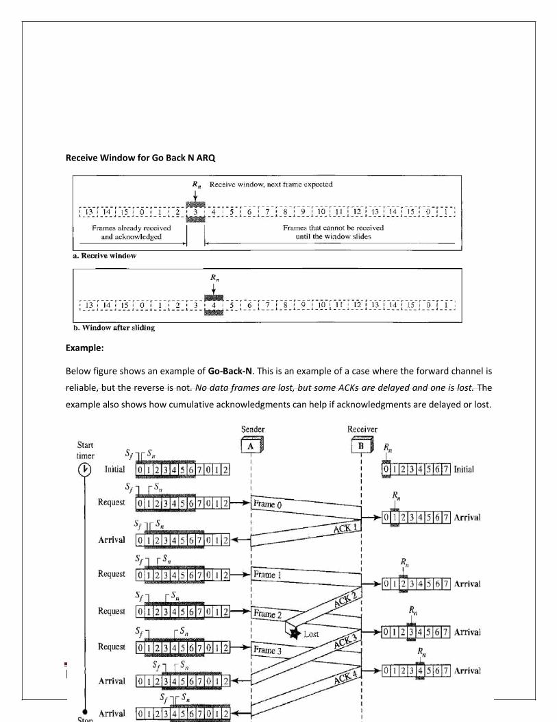
Receive Window for Go Back N ARQ
Example: Below figure shows an example of Go-Back-N. This is an example of a case where the forward channel is
reliable, but the reverse is not. No data frames are lost, but some ACKs are delayed and one is lost. The
example also shows how cumulative acknowledgments can help if acknowledgments are delayed or lost.

[Type text] Page 45
Example: Below figure shows what happens when a frame is lost. Frames 0, 1, 2, and 3 are sent. However, frame 1
is lost. The receiver receives frames 2 and 3, but they are discarded because they are received out of
order (frame 1 is expected). The sender receives no acknowledgment about frames 1, 2, or 3. Its timer
finally expires. The sender sends all outstanding frames (1, 2, and 3) because it does not know what is
wrong. Note that the resending of frames l, 2, and 3 is the response to one single event. When the
sender is responding to this event, it cannot accept the triggering of other events. This means that when
ACK 2 arrives, the sender is still busy with sending frame 3. The physica1layer must wait until this event
is completed and the data link layer goes back to its sleeping state. We have shown a vertical line to
indicate the delay. It is the same story with ACK 3; but when ACK 3 arrives, the sender is busy
responding to ACK 2. It happens again when ACK 4 arrives. Note that before the second timer expires, all outstanding frames have been sent and the timer is stopped.

[Type text] Page 46
Go-Back-N ARQ versus Stop-and- Wait ARQ
There is a similarity between Go-Back-NARQ and Stop-and-Wait ARQ. We can say that the Stop-and-
WaitARQ Protocol is actually a Go-Back-NARQ in which there are only two sequence numbers and the
send window size is 1. In other words, m = 1, 2m - 1 = 1. In Go-Back-NARQ, we said that the addition is modulo-2m; in Stop-and-WaitARQ it is 2, which is the same as 2m when m = 1.
Selective Repeat Automatic Repeat Request
Go-Back-N ARQ simplifies the process at the receiver site. The receiver keeps track of only one
variable, and there is no need to buffer out-of-order frames; they are simply discarded.
However, this protocol is very inefficient for a noisy link. In a noisy link a frame has a higher
probability of damage, which means the resending of multiple frames.
This resending uses up the bandwidth and slows down the transmission. For noisy links, there is
another mechanism that does not resend N frames when just one frame is damaged; only the
damaged frame is resent. This mechanism is called Selective Repeat ARQ. Windows
The Selective Repeat Protocol also uses two windows: a send window and a receive window. However,
there are differences between the windows in this protocol and the ones in Go-Back-N. First, the size of
the send window is much smaller; it is 2m-1. Second, the receive window is the same size as the send
window.
Send window for selective repeat ARQ
The send window maximum size can be 2m- 1. For example, if m = 4, the sequence numbers go from 0 to
15, but the size of the window is just 8 (it is 15 in the Go-Back-N Protocol). The smaller window size
means less efficiency in filling the pipe, but the fact that there are fewer duplicate frames can
compensate for this. The protocol uses the same variables as we discussed for Go-Back-N.

[Type text] Page 47
Receive window for selective repeat ARQ
The receive window in Selective Repeat is totally different from the one in GoBack-N. First, the size
of the receive window is the same as the size of the send window (2m- 1 ).
22. What is Piggybacking ?
Data frames flow in only one direction although control information such as ACK and NAK
frames can travel in the other direction. In real life, data frames are normally flowing in both
directions: from node A to node B and from node B to node A. This means that the control
information also needs to flow in both directions.
When a frame is carrying data from A to B, it can also carry control information about arrived (or
lost) frames from B; when a frame is carrying data from B to A, it can also carry control
information about the arrived (or lost) frames from A. This is called Piggybacking.
Piggybacking is used to improve the efficiency of the bidirectional protocols.

[Type text] Page 48
23. Explain the Point to Point Protocol in detail.
Although HDLC is a general protocol that can be used for both point-to-point and multipoint
configurations, one of the most common protocols for point-to-point access is the Point-to-Point
Protocol (PPP). Today, millions of Internet users who need to connect their home computers to the server of an Internet service provider use PPP.
PPP provides several services:
1. PPP defines the format of the frame to be exchanged between devices. 2. PPP defines how two devices can negotiate the establishment of the link and the exchange of data. 3. PPP defines how network layer data are encapsulated in the data link frame. 4. PPP defines how two devices can authenticate each other. 5. PPP provides multiple network layer services supporting a variety of network layer protocols. 6. PPP provides connections over multiple links. 7. PPP provides network address configuration. This is particularly useful when a home user needs a
temporary network address to connect to the Internet.
On the other hand, to keep PPP simple, several services are missing:
I. PPP does not provide flow control. A sender can send several frames one after another with no
concern about overwhelming the receiver.
2. PPP has a very simple mechanism for error control. A CRC field is used to detect errors. If the frame is
corrupted, it is silently discarded; the upper-layer protocol needs to take care of the problem. Lack of
error control and sequence numbering may cause a packet to be received out of order. 3. PPP does not provide a sophisticated addressing mechanism to handle frames in a multipoint
configuration.
Frame Format of PPP

[Type text] Page 49
Flag: A PPP frame starts and ends with a I-byte flag with the bit pattern 01111110. Although this pattern
is the same as that used in HDLC, there is a big difference. PPP is a byte-oriented protocol; HDLC is a bit-
oriented protocol.
Address: The address field in this protocol is a constant value and set to 11111111 (broadcast address).
During negotiation (discussed later), the two parties may agree to omit this byte.
Control: This field is set to the constant value 11000000 (imitating unnumbered frames in HDLC). PPP
does not provide any flow control. Error control is also limited to error detection. This means that this
field is not needed at all, and again, the two parties can agree, during negotiation, to omit this byte.
Protocol: The protocol field defines what is being carried in the data field: either user data or other
information. We discuss this field in detail shortly. This field is by default 2 bytes long, but the two
parties can agree to use only I byte.
Payload field: This field carries either the user data or other information that we will discuss shortly. The
data field is a sequence of bytes with the default of a maximum of 1500 bytes; but this can be changed
during negotiation. The data field is byte stuffed if the flag byte pattern appears in this field. Because
there is no field defining the size of the data field, padding is needed if the size is less than the maximum
default value or the maximum negotiated value. FCS: The frame check sequence (FCS) is simply a 2-byte or 4-byte standard CRC.
Transition Phases A PPP connection goes through phases which can be shown in a transition phase diagram.

[Type text] Page 50
Dead: In the dead phase the link is not being used. There is no active carrier (at the physical layer) and
the line is quiet.
Establish: When one of the nodes starts the communication, the connection goes into this phase. In this
phase, options are negotiated between the two parties. If the negotiation is successful, the system goes
to the authentication phase (if authentication is required) or directly to the networking phase. The link
control protocol packets, discussed shortly, are used for this purpose. Several packets may be
exchanged here. Authenticate: The authentication phase is optional; the two nodes may decide, during the
establishment phase, not to skip this phase. However, if they decide to proceed with authentication,
they send several authentication packets, discussed later. If the result is successful, the connection goes
to the networking phase; otherwise, it goes to the termination phase.
Network: In the network phase, negotiation for the network layer protocols takes place. PPP specifies
that two nodes establish a network layer agreement before data at the network layer can be exchanged.
The reason is that PPP supports multiple protocols at the network layer. If a node is running multiple
protocols simultaneously at the network layer, the receiving node needs to know which protocol will
receive the data. Open: In the open phase, data transfer takes place. When a connection reaches this phase, the
exchange of data packets can be started. The connection remains in this phase until one of the
endpoints wants to terminate the connection.
Terminate: In the termination phase the connection is terminated. Several packets are exchanged
between the two ends for house cleaning and closing the link.
24. Explain the MULTIPLE ACCESS PROTOCOLS in detail.
Many formal protocols have been devised to handle access to a shared link. We categorize them into three groups. Protocols belonging to each group are shown in below figure:

[Type text] Page 51
RANDOM ACCESS
In random access or contention methods, no station is superior to another station and none is
assigned the control over another. No station permits, or does not permit, another station to
send.
At each instance, a station that has data to send uses a procedure defined by the protocol to
make a decision on whether or not to send. This decision depends on the state of the medium
(idle or busy). In other words, each station can transmit when it desires on the condition that it
follows the predefined procedure, including the testing of the state of the medium.
Two features give this method its name. First, there is no scheduled time for a station to
transmit. Transmission is random among the stations. That is why these methods are called
random access. Second, no rules specify which station should send next. Stations compete with
one another to access the medium. That is why these methods are also called contention
methods.
In a random access method, each station has the right to the medium without being controlled
by any other station. However, if more than one station tries to send, there is an access conflict-
collision-and the frames will be either destroyed or modified. To avoid access conflict or to
resolve it when it happens, each station follows a procedure that answers the following
questions:
When can the station access the medium?
What can the station do if the medium is busy?
How can the station determine the success or failure of the
transmission? What can the station do if there is an access conflict?
25. Explain the concept of ALOHA
ALOHA, the earliest random access method was developed at the University of Hawaii in early 1970. It
was designed for a radio (wireless) LAN, but it can be used on any shared medium.
Pure ALOHA
The original ALOHA protocol is called pure ALOHA. This is a simple, but elegant
protocol. The idea is that each station sends a frame whenever it has a frame to send.

[Type text] Page 52
However, since there is only one channel to share, there is the possibility of collision between
frames from different stations.
It is obvious that we need to resend the frames that have been destroyed during transmission.
The pure ALOHA protocol relies on acknowledgments from the receiver.
When a station sends a frame, it expects the receiver to send an acknowledgment. If the
acknowledgment does not arrive after a time-out period, the station assumes that the frame (or
the acknowledgment) has been destroyed and resends the frame.
There are four stations (unrealistic assumption) that contend with one another for access to the shared
channel. The figure shows that each station sends two frames; there are a total of eight frames on the
shared medium. Some of these frames collide because multiple frames are in contention for the shared
channel. Below figure shows that only two frames survive: frame 1.1 from station 1 and frame 3.2 from
station 3. We need to mention that even if one bit of a frame coexists on the channel with one bit from
another frame, there is a collision and both will be destroyed.

[Type text] Page 53
Vulnerable time: Let us find the length of time, the vulnerable time, in which there is a possibility of
collision. We assume that the stations send fixed-length frames with each frame taking Tfr s to send.
Pure ALOHA vulnerable time = 2 x Tfr
26. Explain the concept of Slotted Aloha
Slotted ALOHA was invented to improve the efficiency of pure ALOHA. In slotted ALOHA we divide the
time into slots of Tfr s and force the station to send only at the beginning of the time slot.

[Type text] Page 54
slotted ALOHA vulnerable time = Tfr
Carrier Sense Multiple Access (CSMA)
To minimize the chance of collision and, therefore, increase the performance, the CSMA method
was developed.
The chance of collision can be reduced if a station senses the medium before trying to use it.
Carrier sense multiple access (CSMA) requires that each station first listen to the medium (or
check the state of the medium) before sending. In other words, CSMA is based on the principle
"sense before transmit" or "listen before talk." CSMA can reduce the possibility of collision, but
it cannot eliminate it.
[Type text] Page 55
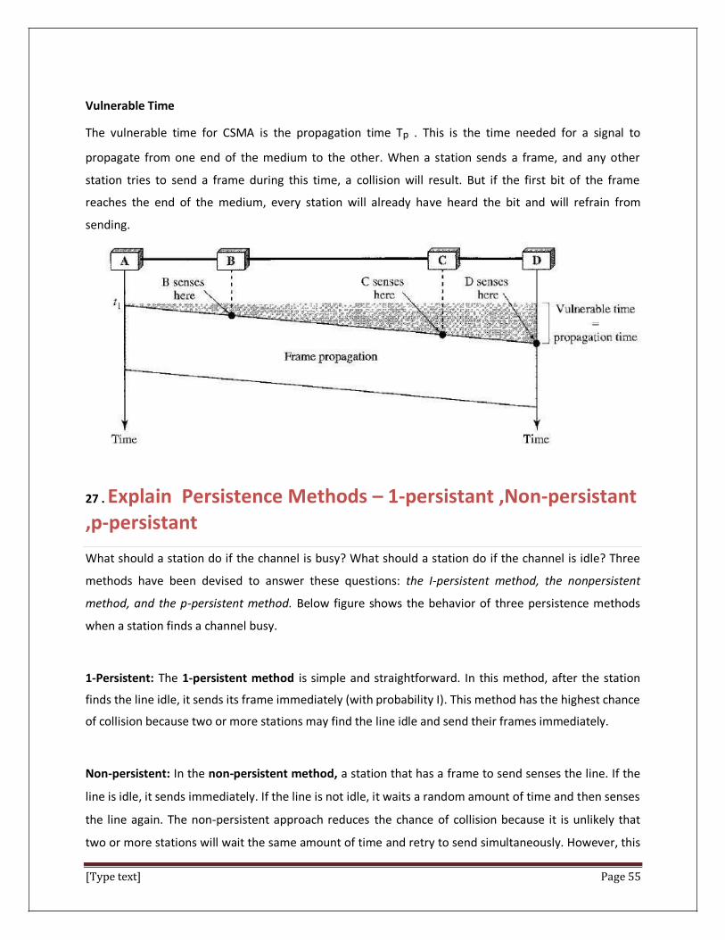
Vulnerable Time
The vulnerable time for CSMA is the propagation time Tp . This is the time needed for a signal to
propagate from one end of the medium to the other. When a station sends a frame, and any other
station tries to send a frame during this time, a collision will result. But if the first bit of the frame
reaches the end of the medium, every station will already have heard the bit and will refrain from
sending.
27 . Explain Persistence Methods – 1-persistant ,Non-persistant ,p-persistant What should a station do if the channel is busy? What should a station do if the channel is idle? Three
methods have been devised to answer these questions: the I-persistent method, the nonpersistent
method, and the p-persistent method. Below figure shows the behavior of three persistence methods
when a station finds a channel busy.
1-Persistent: The 1-persistent method is simple and straightforward. In this method, after the station
finds the line idle, it sends its frame immediately (with probability I). This method has the highest chance
of collision because two or more stations may find the line idle and send their frames immediately.
Non-persistent: In the non-persistent method, a station that has a frame to send senses the line. If the
line is idle, it sends immediately. If the line is not idle, it waits a random amount of time and then senses
the line again. The non-persistent approach reduces the chance of collision because it is unlikely that
two or more stations will wait the same amount of time and retry to send simultaneously. However, this
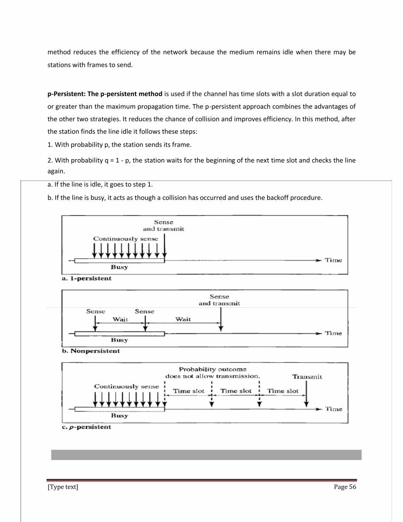
[Type text] Page 56
method reduces the efficiency of the network because the medium remains idle when there may be
stations with frames to send.
p-Persistent: The p-persistent method is used if the channel has time slots with a slot duration equal to
or greater than the maximum propagation time. The p-persistent approach combines the advantages of
the other two strategies. It reduces the chance of collision and improves efficiency. In this method, after
the station finds the line idle it follows these steps: 1. With probability p, the station sends its frame. 2. With probability q = 1 - p, the station waits for the beginning of the next time slot and checks the line
again. a. If the line is idle, it goes to step 1. b. If the line is busy, it acts as though a collision has occurred and uses the backoff procedure.

[Type text] Page 57
27. Explain the CSMA in detail. Carrier Sense Multiple Access with Collision Detection (CSMA/CD)
The CSMA method does not specify the procedure following a collision. Carrier sense multiple access
with collision detection (CSMA/CD) augments the algorithm to handle the collision.
Carrier Sense Multiple Access with Collision Avoidance (CSMA/CA)
The basic idea behind CSMA/CD is that a station needs to be able to receive while transmitting to detect
a collision. When there is no collision, the station receives one signal: its own signal. When there is a
collision, the station receives two signals: its own signal and the signal transmitted by a second station.
To distinguish between these two cases, the received signals in these two cases must be significantly
different. In other words, the signal from the second station needs to add a significant amount of energy
to the one created by the first station. In a wired network, the received.
CONTROLLED ACCESS
In controlled access, the stations consult one another to find which station has the right to send. A
station cannot send unless it has been authorized by other stations. There are three popular controlled-access methods:

[Type text] Page 58
Reservation: In the reservation method, a station needs to make a reservation before sending data.
Time is divided into intervals. In each interval, a reservation frame precedes the data frames sent in that
interval.
Polling: Polling works with topologies in which one device is designated as a primary station and the
other devices are secondary stations. All data exchanges must be made through the primary device even
when the ultimate destination is a secondary device. The primary device controls the link; the secondary
devices follow its instructions. It is up to the primary device to determine which device is allowed to use
the channel at a given time. If the primary wants to receive data, it asks the secondary if they have anything to send; this is called
poll function. If the primary wants to send data, it tells the secondary to get ready to receive; this is
called select function.
1. Select
The select function is used whenever the primary device has something to send. Remember that
the primary controls the link. If the primary is neither sending nor receiving data, it knows the
link is available.
2. Poll
The poll function is used by the primary device to solicit transmissions from the secondary
devices. When the primary is ready to receive data, it must ask (poll) each device in turn if it has
anything to send.

[Type text] Page 59
Token Passing: In the token-passing method, the stations in a network are organized in a logical ring. In
other words, for each station, there is a predecessor and a successor. The predecessor is the station
which is logically before the station in the ring; the successor is the station which is after the station in
the ring. The current station is the one that is accessing the channel now. The right to this access has
been passed from the predecessor to the current station. The right will be passed to the successor when
the current station has no more data to send.

[Type text] Page 60
28. Explain the CHANNELIZATION – FDMA , TDMA, CDMA
Channelization is a multiple-access method in which the available bandwidth of a link is shared in time,
frequency, or through code, between different stations.
Frequency-Division Multiple Access (FDMA)
In frequency-division multiple access (FDMA), the available bandwidth is divided into frequency
bands. Each station is allocated a band to send its data.
Time-Division Multiple Access (TDMA)
In time-division multiple access (TDMA), the stations share the bandwidth of the channel in
time. Each station is allocated a time slot during which it can send data. Each station transmits
its data in is assigned time slot.

[Type text] Page 61
Code-Division Multiple Access (CDMA)
CDMA differs from FDMA because only one channel occupies the entire bandwidth of the link. It
differs from TDMA because all stations can send data simultaneously; there is no timesharing.
29. Explain the concept of Token Bus (IEEE 802.4)
Token bus is a network implementing the token ring protocol over a "virtual ring" on a coaxial cable. A
token is passed around the network nodes and only the node possessing the token may transmit. If a
node doesn't have anything to send, the token is passed on to the next node on the virtual ring. Each
node must know the address of its neighbor in the ring, so a special protocol is needed to notify the
other nodes of connections to, and disconnections from, the ring.
Token bus was standardized by IEEE standard 802.4. It is mainly used for industrial applications. Token
bus was used by General Motors for their Manufacturing Automation Protocol (MAP) standardization
effort. This is an application of the concepts used in token ring networks. The main difference is that the
endpoints of the bus do not meet to form a physical ring.
Token Bus suffered from two limitations. Any failure in the bus caused all the devices beyond the failure
to be unable to communicate with the rest of the network. Second, adding more stations to the bus was
somewhat difficult. Any new station that was improperly attached was unlikely to be able to

[Type text] Page 62
communicate and all devices beyond it were also affected. Thus, token bus networks were seen as
somewhat unreliable and difficult to expand and upgrade.
In order to guarantee the packet delay and transmission in Token bus protocol, a modified Token bus
was proposed in Manufacturing Automation Systems and flexible manufacturing system (FMS).
A means for carrying Internet Protocol over token bus was developed.
30. Explain the concept of Token ring (IEEE 802.5)
Token ring local area network (LAN) technology is a local area network protocol which resides at the
data link layer (DLL) of the OSI model. It uses a special three-byte frame called a token that travels
around the ring. Token-possession grants the possessor permission to transmit on the medium. Token
ring frames travel completely around the loop.
Stations on a token ring LAN are logically organized in a ring topology with data being transmitted
sequentially from one ring station to the next with a control token circulating around the ring controlling
access. This token passing mechanism is shared by ARCNET, token bus, and FDDI, and has theoretical
advantages over the stochastic CSMA/CD of Ethernet.
Physically, a token ring network is wired as a star, with 'hubs' and arms out to each station and the loop
going out-and-back through each.
Each station passes or repeats the special token frame around the ring to its nearest downstream
neighbor. This token-passing process is used to arbitrate access to the shared ring media. Stations that
have data frames to transmit must first acquire the token before they can transmit them. Token ring
LANs normally use differential Manchester encoding of bits on the LAN media.

[Type text] Page 63
Token Ring does come with a higher price tag because token ring hardware is more complex and more
expensive to manufacture. As a network technology, token ring is passing out of use because it has a
maximum speed of 16 Mbps which is slow by today's gigabit Ethernet standards.
31. What do you mean by Wireless LANs? Wireless communication is one of the fastest-growing technologies. The demand for connecting devices without the use of cables is increasing everywhere. Wireless LANs can be found on college campuses, in office buildings, and in many public areas.
32. What do you mean by ATM ?
Asynchronous Transfer Mode (ATM) is a standard switching technique, designed to
unify telecommunication and computer networks. It uses asynchronous time-division multiplexing, and
it encodes data into small, fixed-sized cells. This differs from approaches such as the Internet
Protocol or Ethernet that use variable sized packets or frames. ATM provides data link layer services that run over a wide range of OSI physical Layer links. ATM has functional similarity with both circuit
switched networking and small packet switched networking. It was designed for a network that must
handle both traditional high-throughput data traffic (e.g., file transfers), and real-time, low-latency
content such as voice and video. ATM uses a connection-oriented model in which a virtual circuit must
be established between two endpoints before the actual data exchange begins.

[Type text] Page 64
33. Explain the concept of Simple Mail Transfer Protocol (SMTP)
Simple Mail Transfer Protocol (SMTP) is an Internet standard for electronic mail (e-mail) transmission
across Internet Protocol (IP) networks.
SMTP is a connection-oriented, text-based protocol in which a mail sender communicates with a mail
receiver by issuing command strings and supplying necessary data over a reliable ordered data stream
channel, typically a Transmission Control Protocol (TCP) connection. An SMTP session consists of
commands originated by an SMTP client (the initiating agent, sender, or transmitter) and corresponding
responses from the SMTP server (the listening agent, or receiver) so that the session is opened, and
session parameters are exchanged. A session may include zero or more SMTP transactions. An SMTP
transaction consists of three command/reply sequences (see example below.) They are:
1. MAIL command, to establish the return address, a.k.a. Return-Path, 5321.From, mfrom, or
envelope sender. This is the address for bounce messages.
2. RCPT command, to establish a recipient of this message. This command can be issued multiple
times, one for each recipient. These addresses are also part of the envelope.
3. DATA to send the message text. This is the content of the message, as opposed to its envelope.
It consists of a message header and a message body separated by an empty line. DATA is
actually a group of commands, and the server replies twice: once to the DATA command
proper, to acknowledge that it is ready to receive the text, and the second time after the end-
of-data sequence, to either accept or reject the entire message.

[Type text] Page 65
34. Explain the concept of FTP File Transfer Protocol (FTP)
File Transfer Protocol (FTP) is the standard mechanism provided by TCP/IP for copying a file
from one host to another. Although transferring files from one system to another seems simple
and straightforward, some problems must be dealt with first. For example, two systems may use
different file name conventions. Two systems may have different ways to represent text and
data. Two systems may have different directory structures. All these problems have been solved
by FTP in a very simple and elegant approach.
FTP differs from other client/server applications in that it establishes two connections between
the hosts. One connection is used for data transfer, the other for control information
(commands and responses). Separation of commands and data transfer makes FTP more
efficient. The control connection uses very simple rules of communication.
We need to transfer only a line of command or a line of response at a time. The data
connection, on the other hand, needs more complex rules due to the variety of data types
transferred. However, the difference in complexity is at the FTP level, not TCP.
For TCP, both connections are treated the same.FTP uses two well-known TCP ports: Port 21 is
used for the control connection, and port 20 is used for the data connection.

[Type text] Page 66
35. Explain the concept of WWW . WWW
The World Wide Web (WWW) is a repository of information linked together from points all over
the world. The WWW has a unique combination of flexibility, portability, and user-friendly
features that distinguish it from other services provided by the Internet.
Each site holds one or more documents, referred to as Web pages. Each Web page can contain a
link to other pages in the same site or at other sites. The pages can be retrieved and viewed by
using browsers.
Client (Browser)
A variety of vendors offer commercial browsers that interpret and display a Web document, and all use
nearly the same architecture. Each browser usually consists of three parts: a controller, client protocol,
and interpreters. The controller receives input from the keyboard or the mouse and uses the client
programs to access the document. After the document has been accessed, the controller uses one of the
interpreters to display the document on the screen. The client protocol can be one of the protocols
described previously such as FTP or HTTP (described later in the chapter). The interpreter can be HTML,
Java, or JavaScript, depending on the type of document.
Server
The Web page is stored at the server. Each time a client request arrives, the corresponding document is
sent to the client. To improve efficiency, servers normally store requested files in a cache in memory;
memory is faster to access than disk. A server can also become more efficient through multithreading or
multiprocessing. In this case, a server can answer more than one request at a time.
Uniform Resource Locator
A client that wants to access a Web page needs the address. To facilitate the access of
documents distributed throughout the world, HTTP uses locators. The uniform resource locator

[Type text] Page 67
(URL) is a standard for specifying any kind of information on the Internet. The URL defines four
things: protocol, host computer, port, and path.
The protocol is the client/server program used to retrieve the document. Many different
protocols can retrieve a document; among them are FTP or HTTP. The most common today is
HTTP.
Protocol://host:port/path
36. Explain the concept of HTTP
The Hypertext Transfer Protocol (HTTP) is a protocol used mainly to access data on the World
Wide Web. HTTP functions as a combination of FTP and SMTP. It is similar to FTP because it
transfers files and uses the services of TCP. However, it is much simpler than FTP because it uses
only one TCP connection. There is no separate control connection; only data are transferred
between the client and the server.
HTTP is like SMTP because the data transferred between the client and the server look like
SMTP messages. In addition, the format of the messages is controlled by MIME-like headers.
Unlike SMTP, the HTTP messages are not destined to be read by humans; they are read and
interpreted by the HTTP server and HTTP client (browser). SMTP messages are stored and
forwarded, but HTTP messages are delivered immediately. The commands from the client to the
server are embedded in a request message. The contents of the requested file or other
information are embedded in a response message. HTTP uses the services of TCP on well-known
port 80.
37. Explain the concept CONGESTION CONTROL ALGORTIHM
Congestion control algorithms Leaky Bucket Algorithm
Let us consider an example to understand Imagine a bucket with a small hole in the bottom.No matter at what rate water enters the bucket, the outflow is at constant rate.When the bucket is full with water additional water entering spills over the sides and is lost.
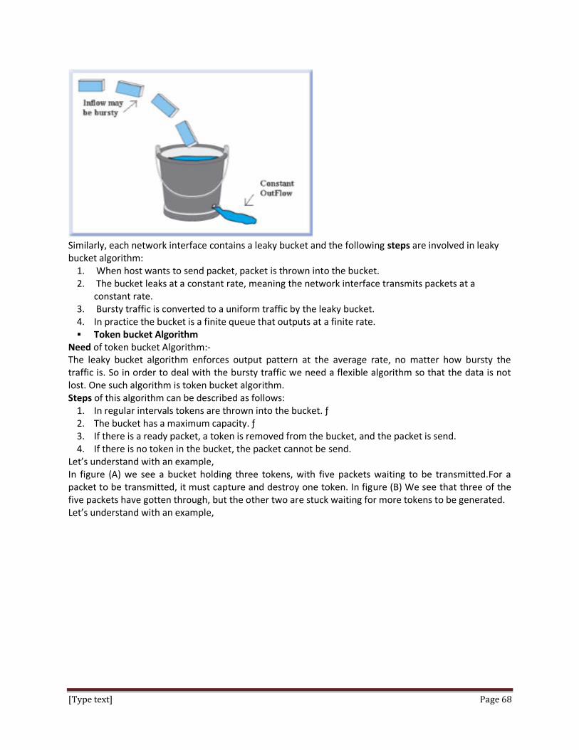
[Type text] Page 68
Similarly, each network interface contains a leaky bucket and the following steps are involved in leaky bucket algorithm:
1. When host wants to send packet, packet is thrown into the bucket. 2. The bucket leaks at a constant rate, meaning the network interface transmits packets at a
constant rate. 3. Bursty traffic is converted to a uniform traffic by the leaky bucket. 4. In practice the bucket is a finite queue that outputs at a finite rate. Token bucket Algorithm
Need of token bucket Algorithm:- The leaky bucket algorithm enforces output pattern at the average rate, no matter how bursty the traffic is. So in order to deal with the bursty traffic we need a flexible algorithm so that the data is not lost. One such algorithm is token bucket algorithm. Steps of this algorithm can be described as follows:
1. In regular intervals tokens are thrown into the bucket. ƒ 2. The bucket has a maximum capacity. ƒ 3. If there is a ready packet, a token is removed from the bucket, and the packet is send. 4. If there is no token in the bucket, the packet cannot be send.
Let’s understand with an example, In figure (A) we see a bucket holding three tokens, with five packets waiting to be transmitted.For a packet to be transmitted, it must capture and destroy one token. In figure (B) We see that three of the five packets have gotten through, but the other two are stuck waiting for more tokens to be generated. Let’s understand with an example,

[Type text] Page 69
***************************************************