Embed Size (px)
Citation preview
1
Dr. Thomas HicksComputer Science Department
Trinity University 1
Data Communication
& Networking CSCI 3342
Must Consider Protocols
2
3
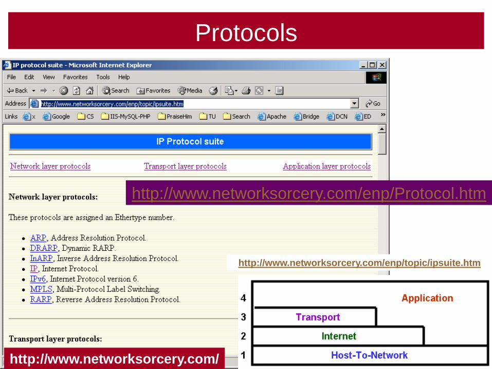
Protocols
http://www.networksorcery.com/enp/topic/ipsuite.htm
http://www.networksorcery.com/enp/Protocol.htm
http://www.networksorcery.com/
Guided & Unguided
Media
4

5
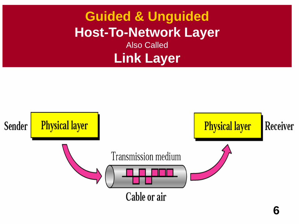
Guided & Unguided Transmission Media
6
Guided & Unguided
Host-To-Network Layer Also Called
Link Layer
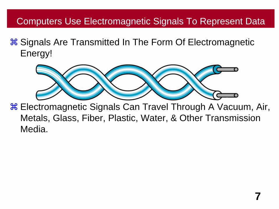
Computers Use Electromagnetic Signals To Represent Data
Signals Are Transmitted In The Form Of Electromagnetic
Energy!
Electromagnetic Signals Can Travel Through A Vacuum, Air,
Metals, Glass, Fiber, Plastic, Water, & Other Transmission
Media.
7
ElectromagneticEnergy
8
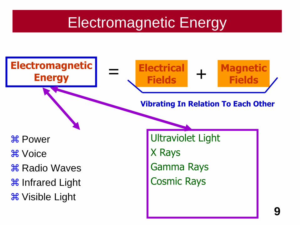
Electromagnetic Energy
Power
Voice
Radio Waves
Infrared Light
Visible Light
9
ElectromagneticEnergy
ElectricalFields
MagneticFields
= +
Vibrating In Relation To Each Other
Ultraviolet Light
X Rays
Gamma Rays
Cosmic Rays

Electromagnetic Spectrum - 1
Power Voice Radio Waves
Infrared Light Visible Light Ultraviolet Light
X Rays Gamma Rays Cosmic Rays
Each Of These Forms Of Electromagnetic Energy Has It’s
Place In The Electromagnetic Spectrum.
10
Where Is Ethernet In
This Spectrum?

Electromagnetic Spectrum - 2
Not All Portions Of The Spectrum Have Been Harnessed For
Data Communications.
Voice-band Frequencies Most Often Use ?
Radio Frequencies Use?
Visible Light Frequencies Use ?
11
Metal Cables
Air
Fiber Optic
Straight Wiring
vs
Twisted Pair
12
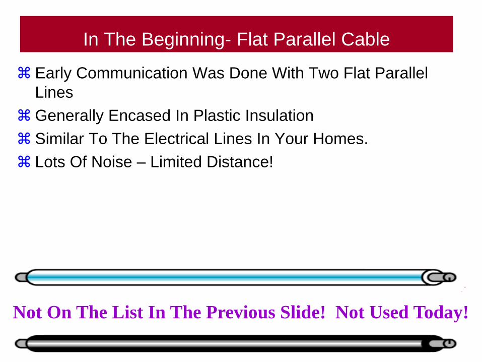
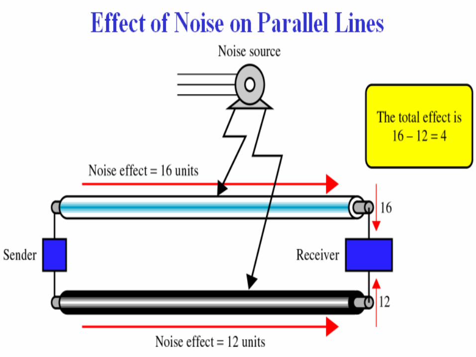
In The Beginning- Flat Parallel Cable
Early Communication Was Done With Two Flat Parallel
Lines
Generally Encased In Plastic Insulation
Similar To The Electrical Lines In Your Homes.
Lots Of Noise – Limited Distance!
13
Not On The List In The Previous Slide! Not Used Today!
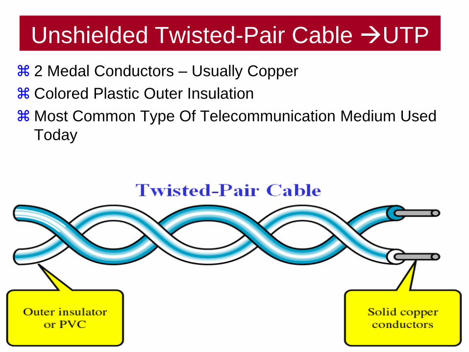
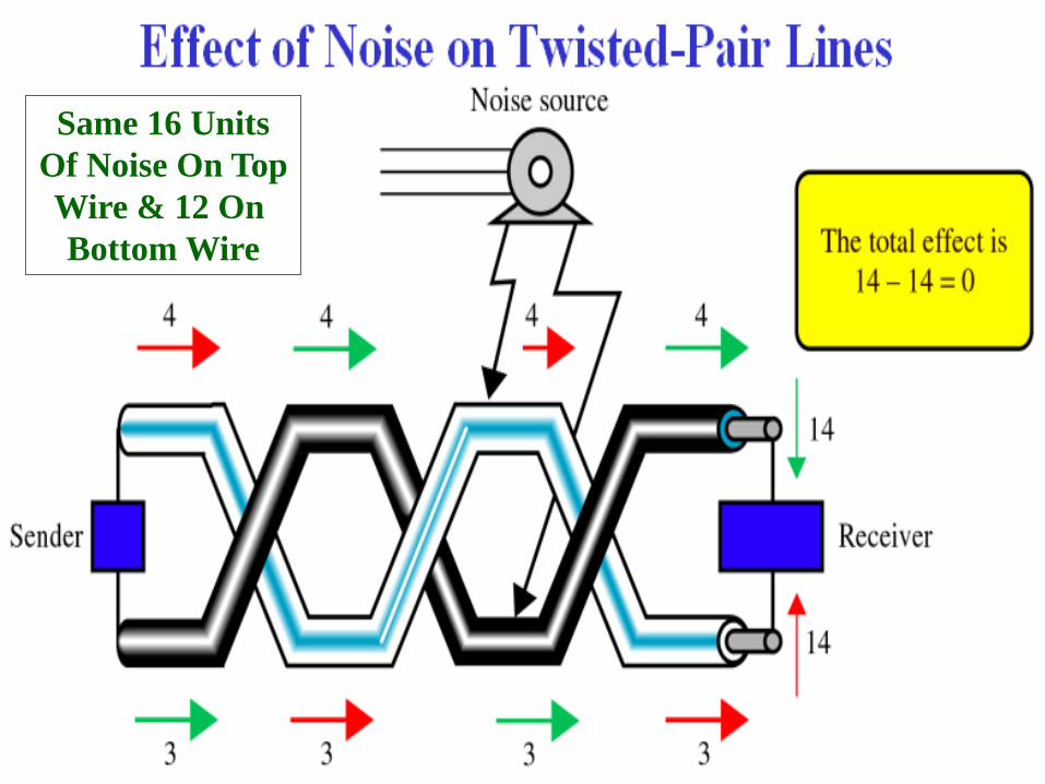
Unshielded Twisted-Pair Cable UTP
2 Medal Conductors – Usually Copper
Colored Plastic Outer Insulation
Most Common Type Of Telecommunication Medium Used
Today
14
15
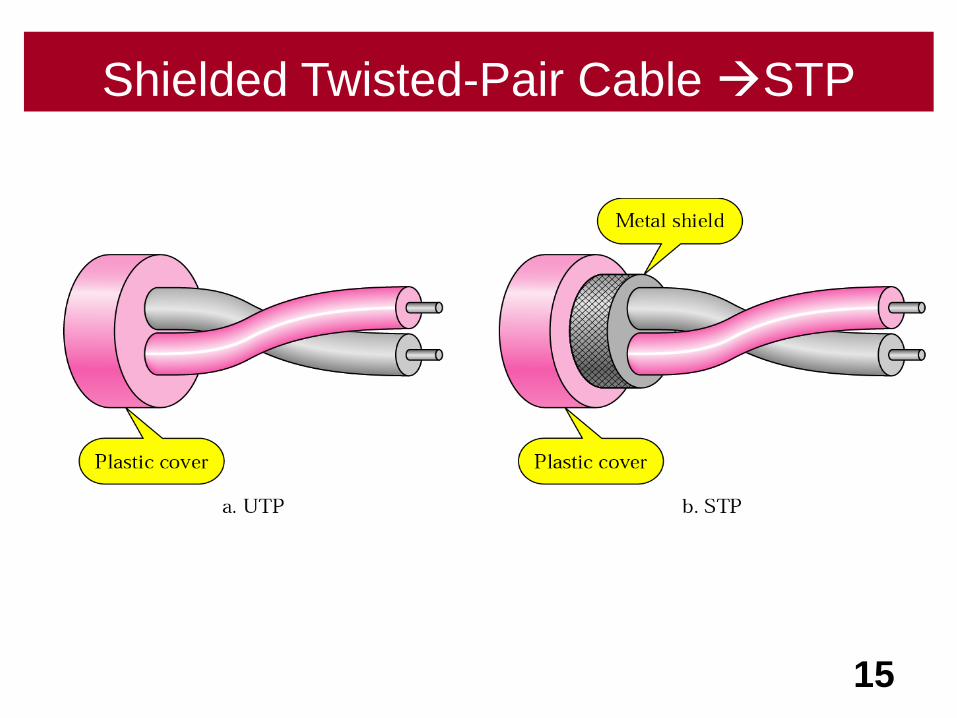
Shielded Twisted-Pair Cable STP
16
17
Same 16 Units
Of Noise On Top
Wire & 12 On
Bottom Wire
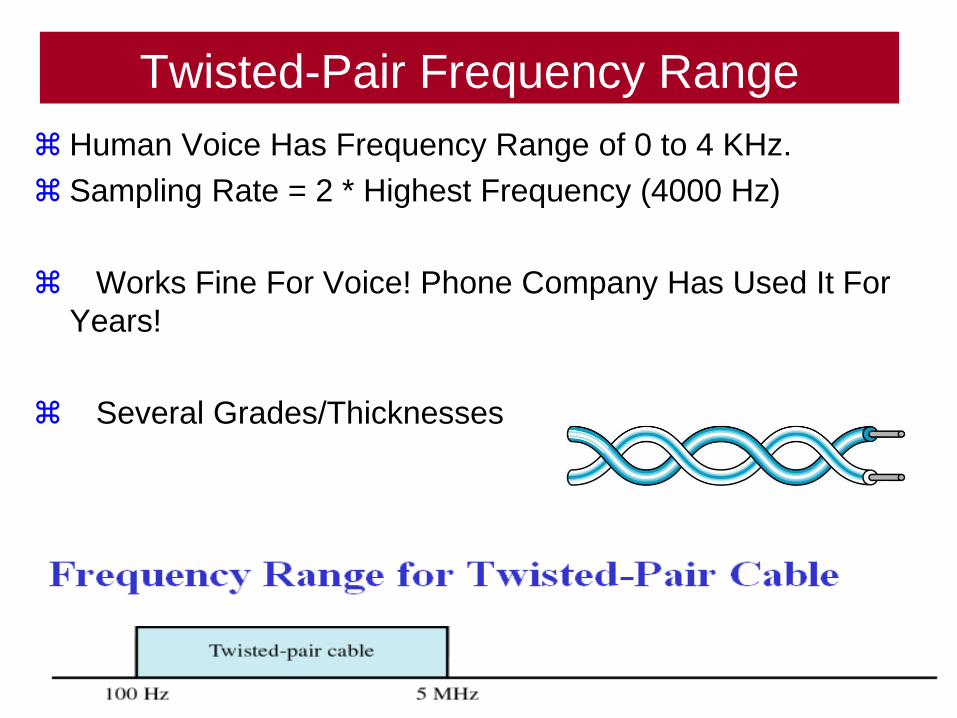
Twisted-Pair Frequency Range
Human Voice Has Frequency Range of 0 to 4 KHz.
Sampling Rate = 2 * Highest Frequency (4000 Hz)
Works Fine For Voice! Phone Company Has Used It For
Years!
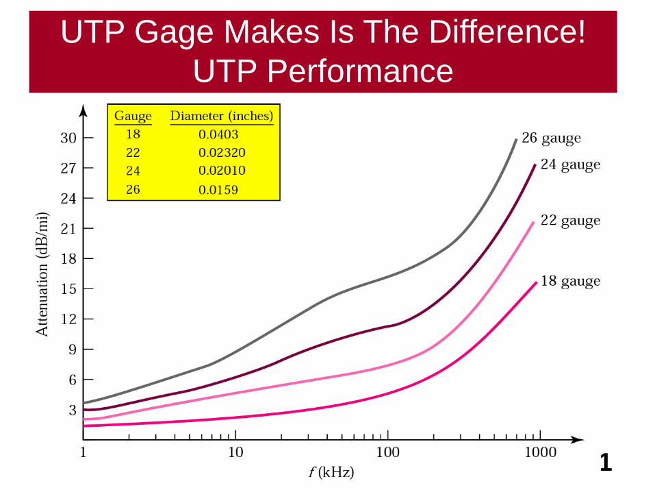
Several Grades/Thicknesses
18
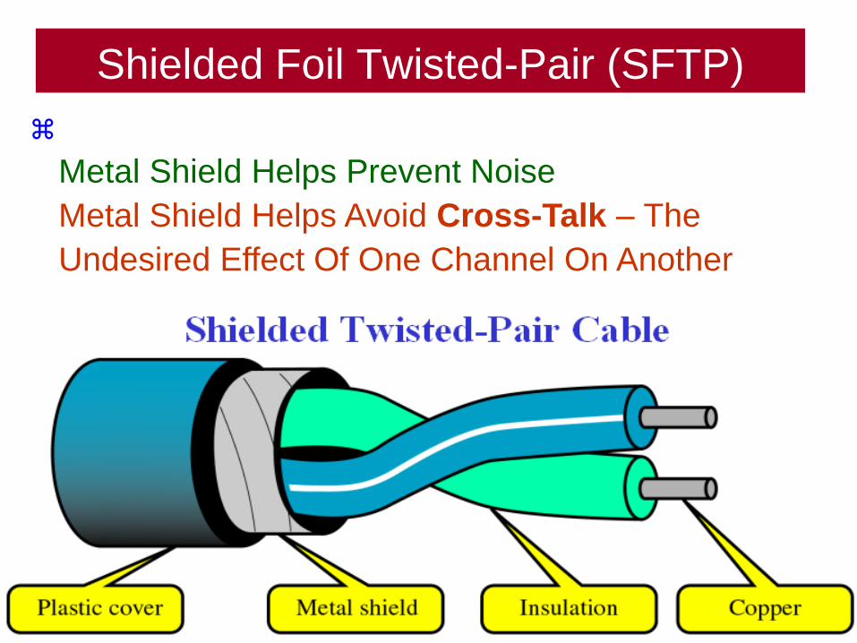
Shielded Foil Twisted-Pair (SFTP)
19
Metal Shield Helps Prevent Noise
Metal Shield Helps Avoid Cross-Talk – The
Undesired Effect Of One Channel On Another
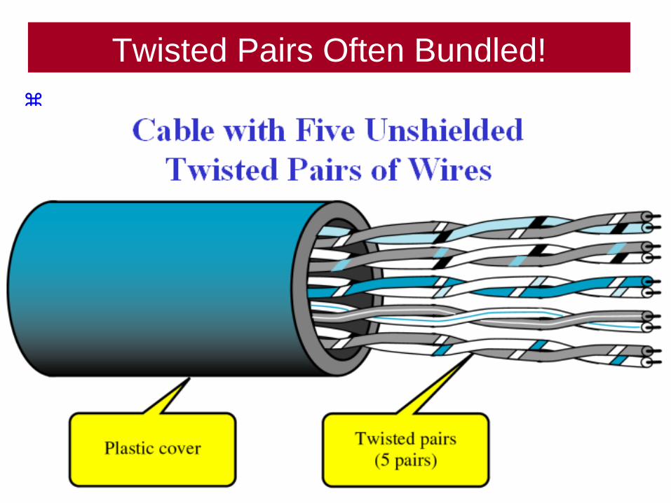
Twisted Pairs Often Bundled!
20
21
UTP Gage Makes Is The Difference!
UTP Performance

Wiring
Categories
22
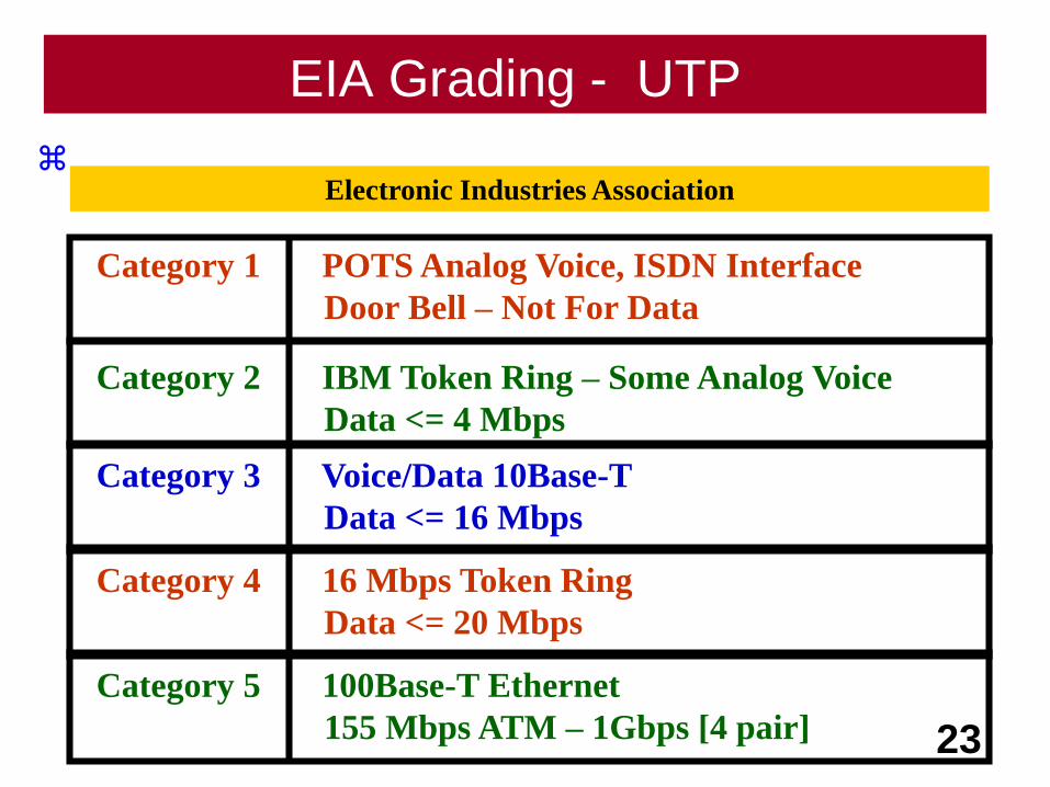
EIA Grading - UTP
23
Category 1 POTS Analog Voice, ISDN Interface
Door Bell – Not For Data
Category 2 IBM Token Ring – Some Analog Voice
Data <= 4 Mbps
Category 3 Voice/Data 10Base-T
Data <= 16 Mbps
Category 4 16 Mbps Token Ring
Data <= 20 Mbps
Category 5 100Base-T Ethernet
155 Mbps ATM – 1Gbps [4 pair]
Electronic Industries Association
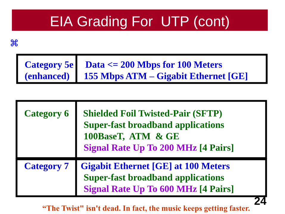
EIA Grading For UTP (cont)
24
Category 5e Data <= 200 Mbps for 100 Meters
(enhanced) 155 Mbps ATM – Gigabit Ethernet [GE]
Category 6 Shielded Foil Twisted-Pair (SFTP)
Super-fast broadband applications
100BaseT, ATM & GE
Signal Rate Up To 200 MHz [4 Pairs]
Category 7 Gigabit Ethernet [GE] at 100 Meters
Super-fast broadband applications
Signal Rate Up To 600 MHz [4 Pairs]
“The Twist" isn't dead. In fact, the music keeps getting faster.
25
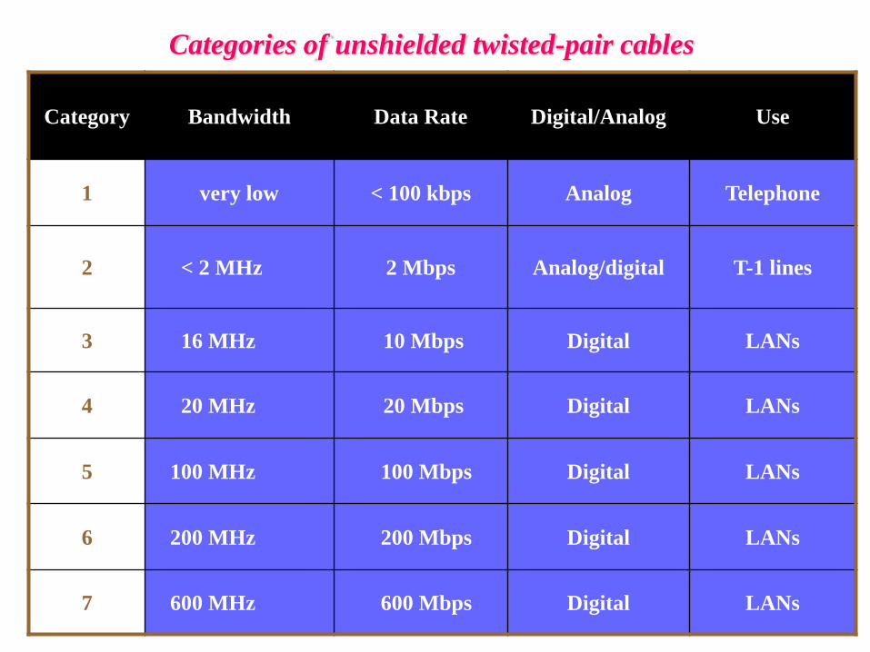
Categories of unshielded twisted-pair cables
Category Bandwidth Data Rate Digital/Analog Use
1 very low < 100 kbps Analog Telephone
2 < 2 MHz 2 Mbps Analog/digital T-1 lines
3 16 MHz 10 Mbps Digital LANs
4 20 MHz 20 Mbps Digital LANs
5 100 MHz 100 Mbps Digital LANs
6 200 MHz 200 Mbps Digital LANs
7 600 MHz 600 Mbps Digital LANs

Prices
Continue To Change
26
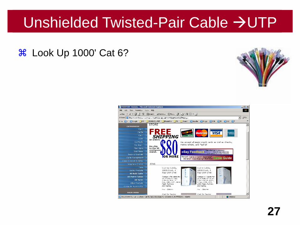
Look Up 1000' Cat 6?
27
1000 ft Costs $69.99Unshielded Twisted-Pair Cable UTP
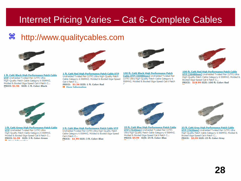
Internet Pricing Varies – Cat 6- Complete Cables
28
http://www.qualitycables.com
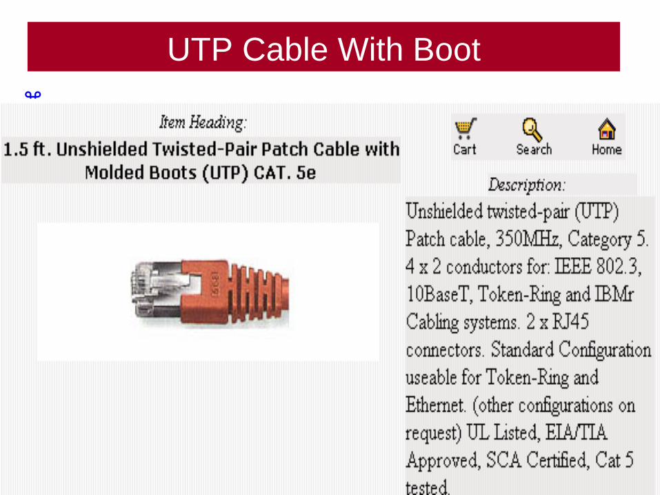
UTP Cable With Boot
29
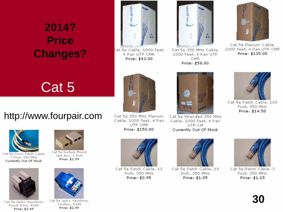
30
Cat 5
http://www.fourpair.com
2014?
Price
Changes?

31
Cat 6
http://www.fourpair.com
2014?
Price
Changes?
Cat 5-6Standards
32
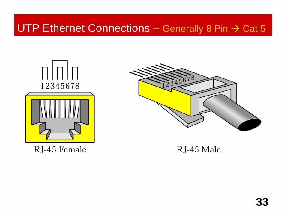
33
UTP Ethernet Connections – Generally 8 Pin Cat 5
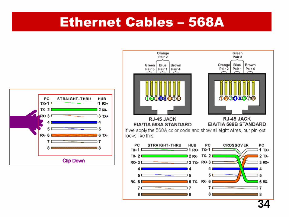
34
Ethernet Cables – 568A
Tools
35

36
Name The Tool!
http://www.fourpair.com

37http://www.fourpair.com
Name The Tool!

38http://www.fourpair.com
Name The Tool!

39http://www.fourpair.com
Name The Tool!

40http://www.fourpair.com
Name The Tool!
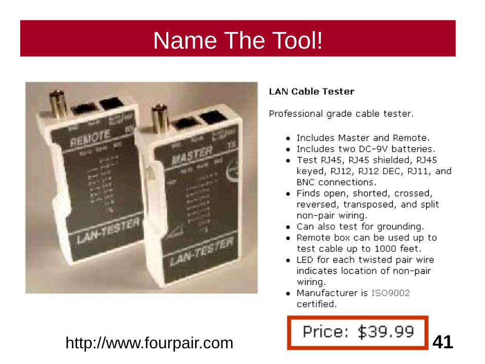
41http://www.fourpair.com
Name The Tool!
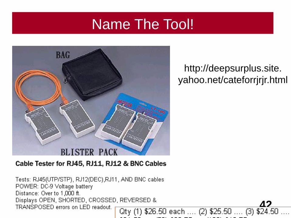
42
http://deepsurplus.site.
yahoo.net/cateforrjrjr.html
Name The Tool!

43http://www.networkingsource.com/502030.html
Name The Tool!

45
Name The Tool!
Coax
46
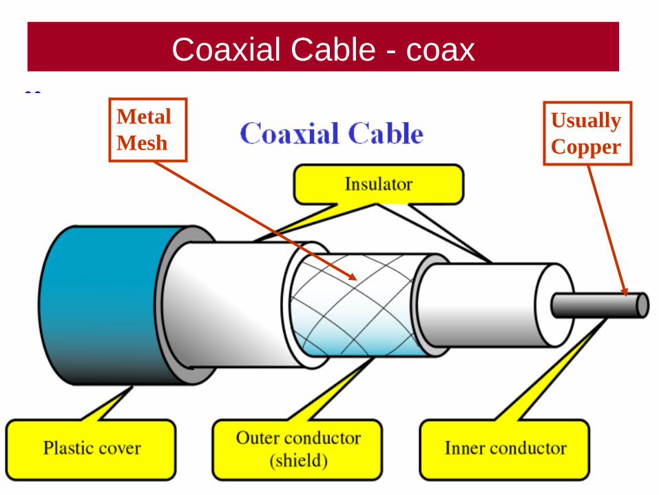
Coaxial Cable - coax
47
Usually
Copper
Metal
Mesh
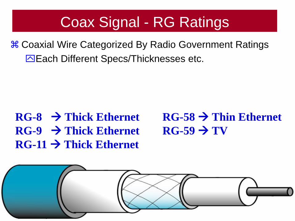
Coax Signal - RG Ratings
Coaxial Wire Categorized By Radio Government Ratings
Each Different Specs/Thicknesses etc.
48
RG-8 Thick Ethernet RG-58 Thin Ethernet
RG-9 Thick Ethernet RG-59 TV
RG-11 Thick Ethernet
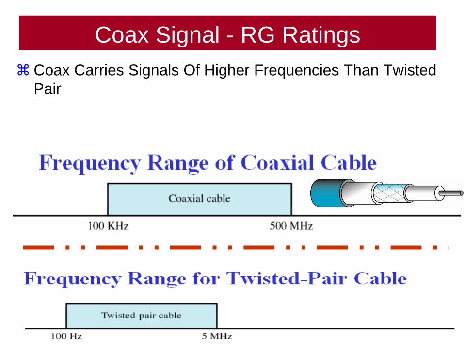
Coax Signal - RG Ratings
Coax Carries Signals Of Higher Frequencies Than Twisted
Pair
49
50
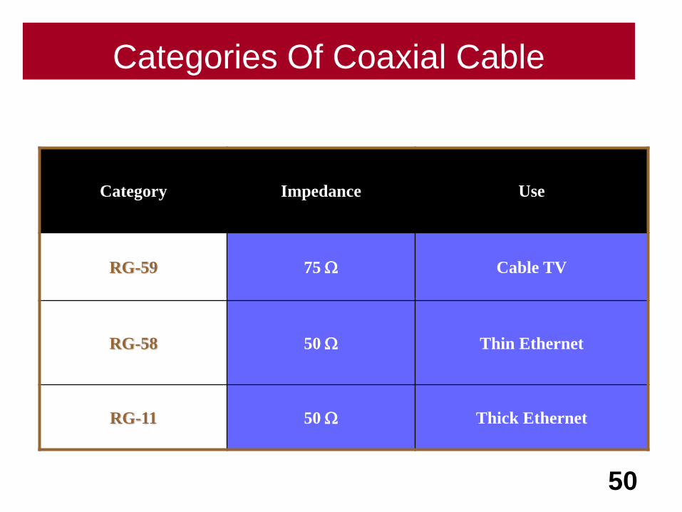
Category Impedance Use
RG-59 75 W Cable TV
RG-58 50 W Thin Ethernet
RG-11 50 W Thick Ethernet
Categories Of Coaxial Cable
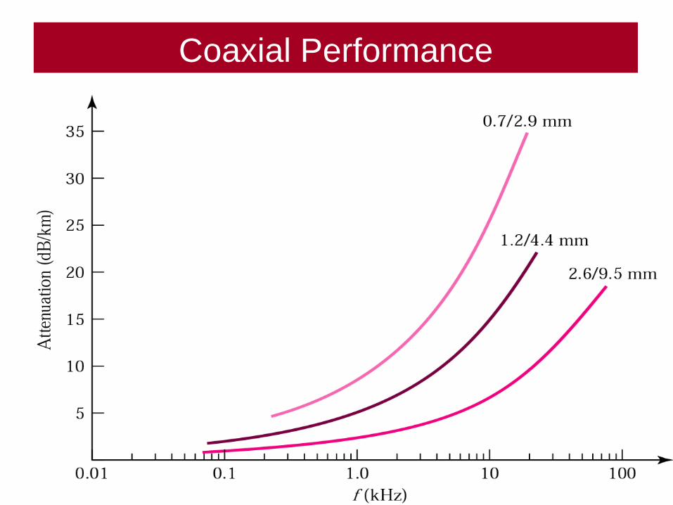
51
Coaxial Performance
BNC
52

53
BNC Connectors
Connectors
54
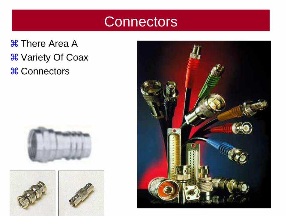
Coax
Connectors
There Area A
Variety Of Coax
Connectors
55
Fiber Optic
56
57
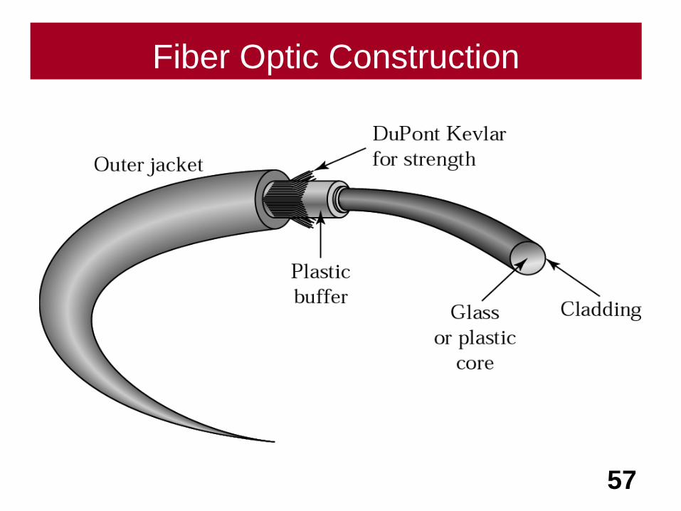
Fiber Optic Construction
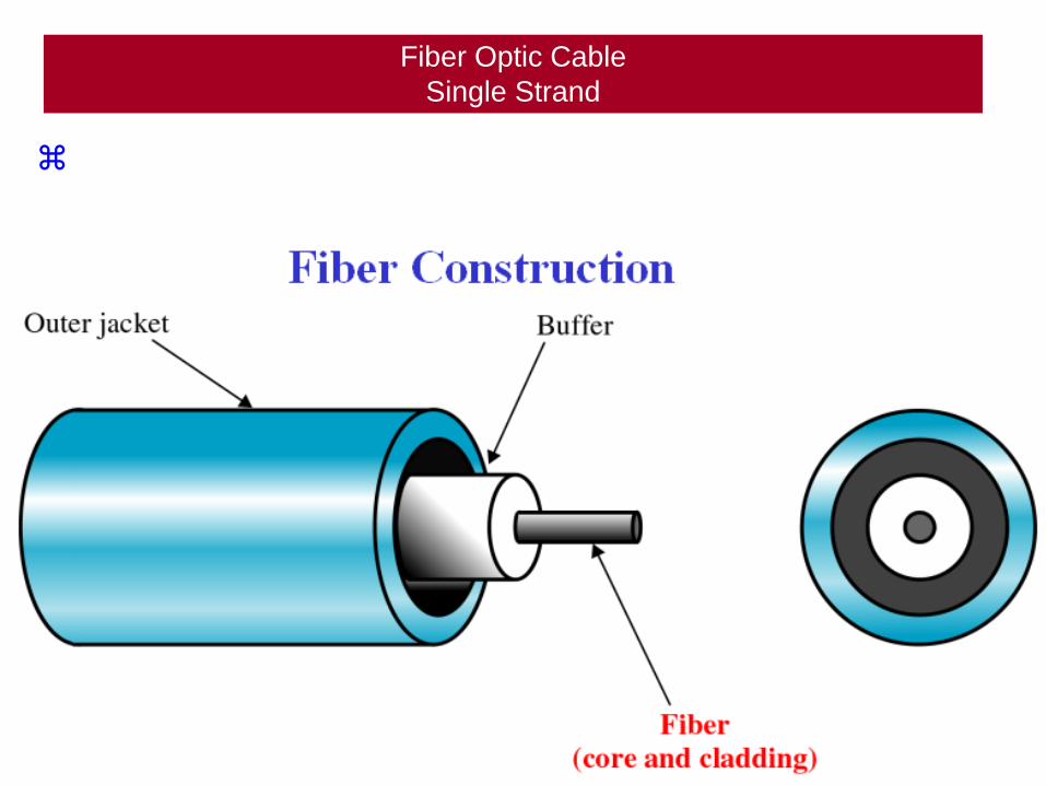
Fiber Optic Cable
Single Strand
58
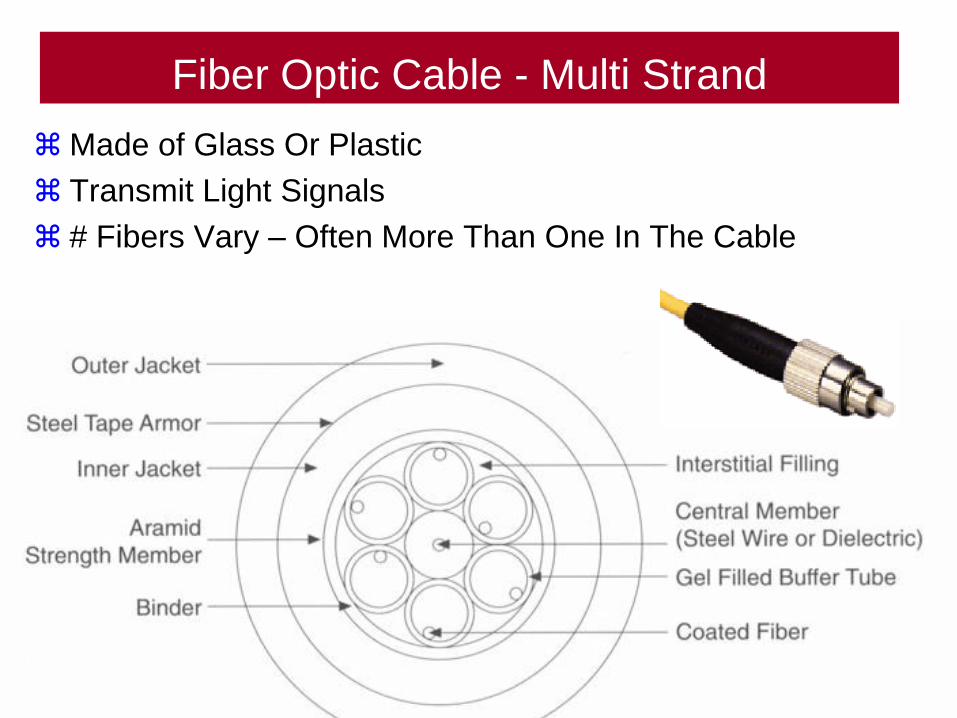
Fiber Optic Cable - Multi Strand
Made of Glass Or Plastic
Transmit Light Signals
# Fibers Vary – Often More Than One In The Cable
59
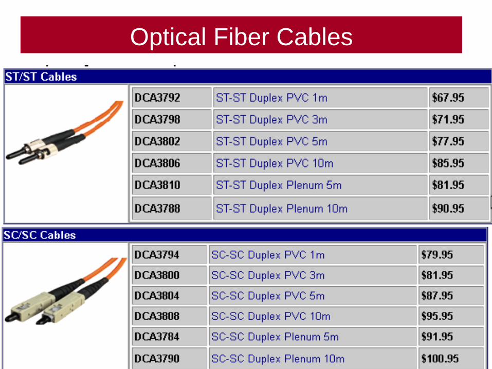
Optical Fiber Cables
60
Optical Fiber Cables
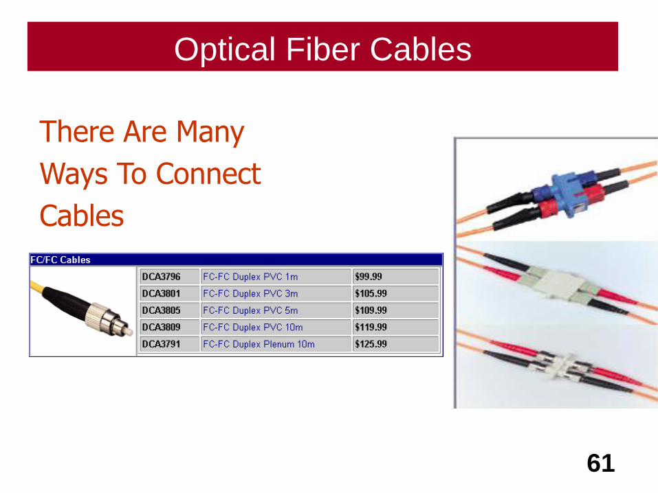
61
There Are Many
Ways To Connect
Cables
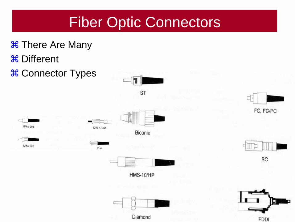
Fiber Optic Connectors
There Are Many
Different
Connector Types
62

63
Fiber Optic Connectors
Fiber Optic Connectors
Connectors Must Be As Precise As The Cable Itself.
Metal Connectors Provide A Greater Degree Of Latitude
With Respect To Length. Fiber Connectors Must Be Ultra
Precise.
If Connectors Overly Tight Alter Angle Reflection.
If Connectors Have A Gap Dissipate Signal.
64
About Fiber Optic Communication
65
Light - 1
Light Travels 186,000 Miles/Second In A Vacuum.
The Speed Of Light Varies With The Density Of The
Medium.
Light Travels In A Straight Line As Long As It Is Moving
Through A Single Substance.
66
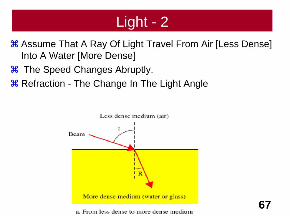
Light - 2
Assume That A Ray Of Light Travel From Air [Less Dense]
Into A Water [More Dense]
The Speed Changes Abruptly.
Refraction - The Change In The Light Angle
67

Light - 3
Refraction - The Change In The Light Angle
A Beam Traveling From Less Dense Into More Dense Is
Bent Toward The Vertical Axis.
68
Vertical Axis
Angle Of Incidence
Angle Of Refraction
AI > AR
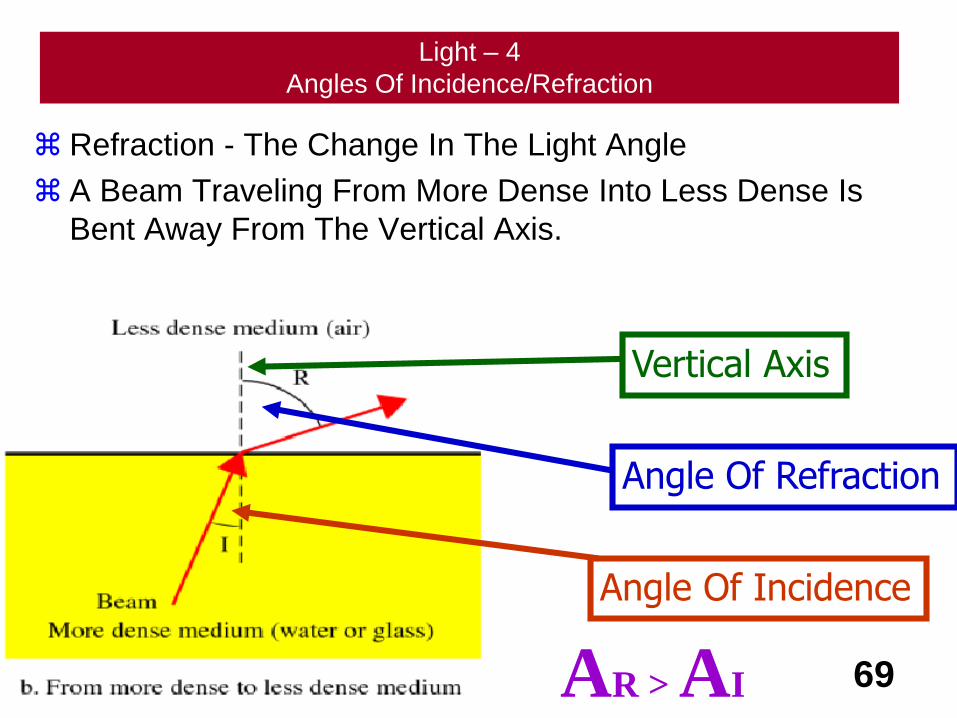
Light – 4
Angles Of Incidence/Refraction
Refraction - The Change In The Light Angle
A Beam Traveling From More Dense Into Less Dense Is
Bent Away From The Vertical Axis.
69
Vertical Axis
Angle Of Incidence
Angle Of Refraction
AR > AI
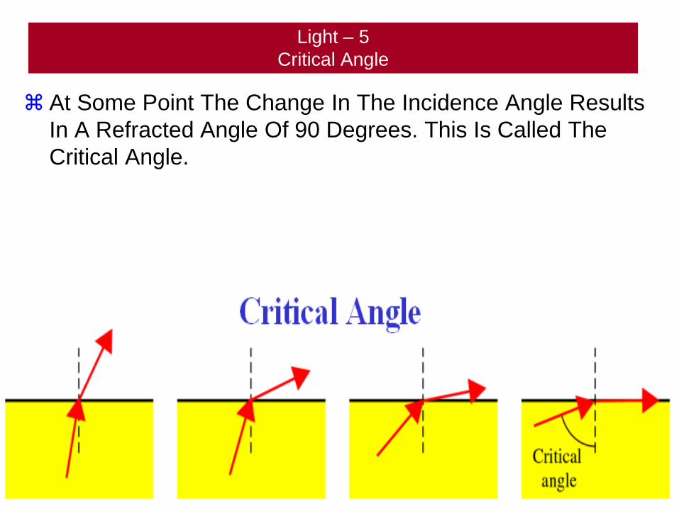
Light – 5
Critical Angle
At Some Point The Change In The Incidence Angle Results
In A Refracted Angle Of 90 Degrees. This Is Called The
Critical Angle.
70
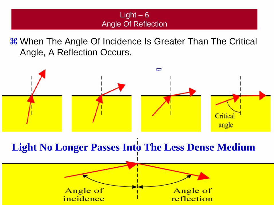
Light – 6
Angle Of Reflection
When The Angle Of Incidence Is Greater Than The Critical
Angle, A Reflection Occurs.
71
Light No Longer Passes Into The Less Dense Medium
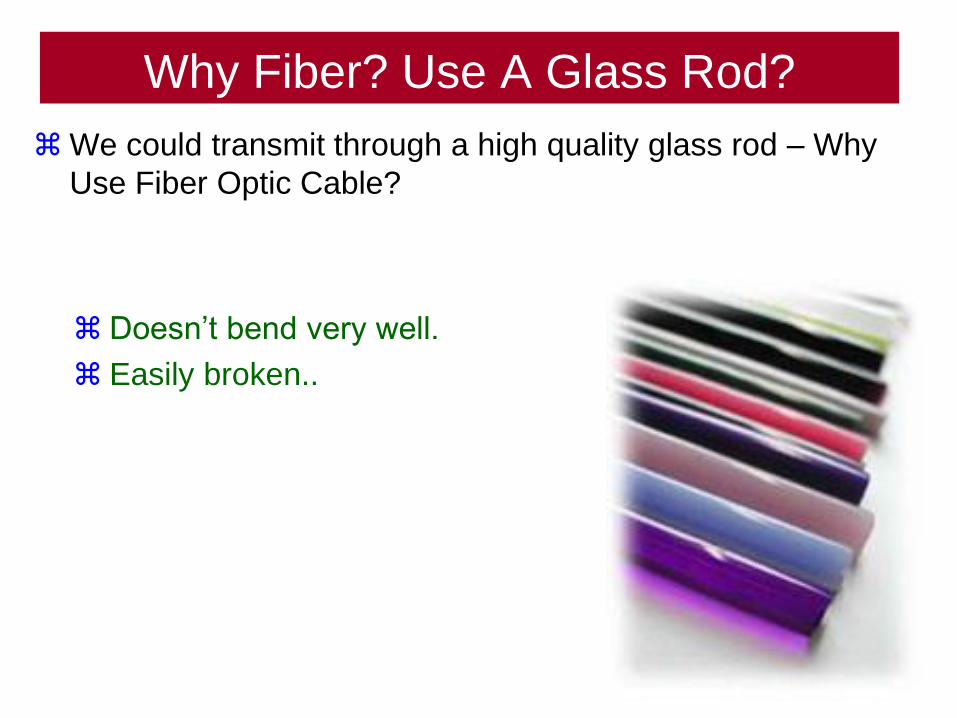
Why Fiber? Use A Glass Rod?
We could transmit through a high quality glass rod – Why
Use Fiber Optic Cable?
72
Doesn’t bend very well.
Easily broken..
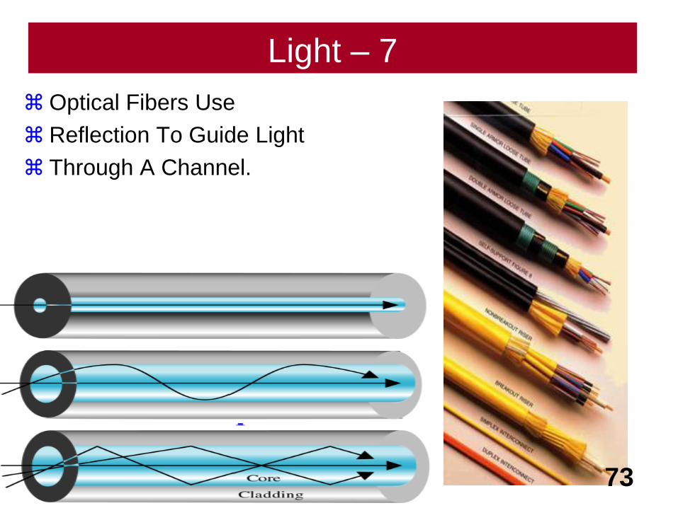
Light – 7
Optical Fibers Use
Reflection To Guide Light
Through A Channel.
73
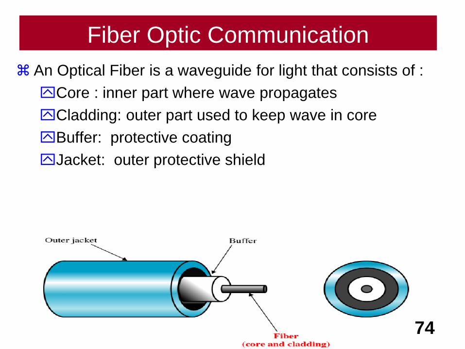
Fiber Optic Communication
An Optical Fiber is a waveguide for light that consists of :
Core : inner part where wave propagates
Cladding: outer part used to keep wave in core
Buffer: protective coating
Jacket: outer protective shield
74
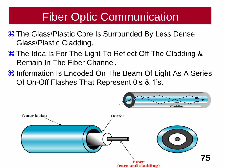
Fiber Optic Communication
The Glass/Plastic Core Is Surrounded By Less Dense
Glass/Plastic Cladding.
The Idea Is For The Light To Reflect Off The Cladding &
Remain In The Fiber Channel.
Information Is Encoded On The Beam Of Light As A Series
Of On-Off Flashes That Represent 0’s & 1’s.
75
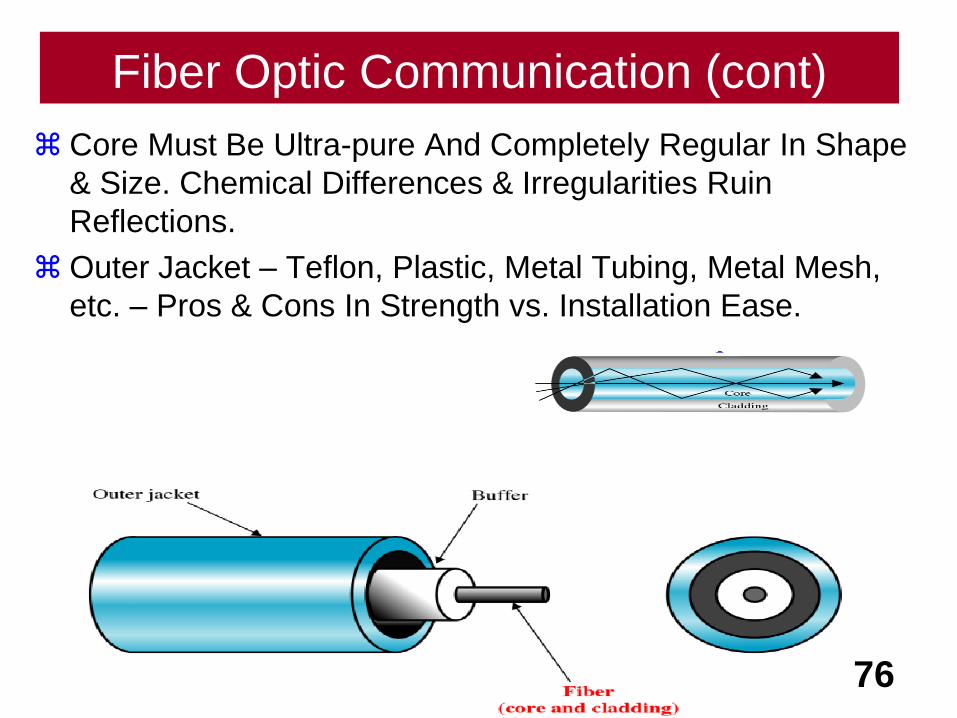
Fiber Optic Communication (cont)
Core Must Be Ultra-pure And Completely Regular In Shape
& Size. Chemical Differences & Irregularities Ruin
Reflections.
Outer Jacket – Teflon, Plastic, Metal Tubing, Metal Mesh,
etc. – Pros & Cons In Strength vs. Installation Ease.
76
Fiber Types
77
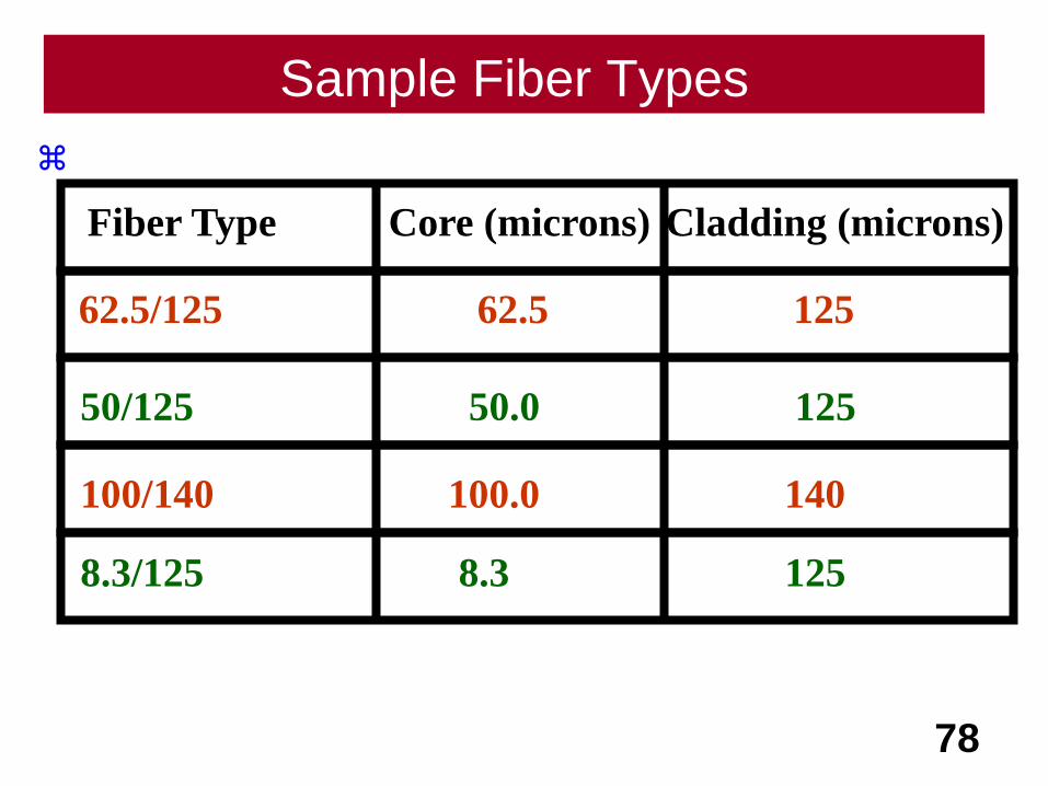
Sample Fiber Types
78
Fiber Type Core (microns) Cladding (microns)
62.5/125 62.5 125
50/125 50.0 125
100/140 100.0 140
8.3/125 8.3 125

79
Type Core Cladding Mode
50/125 50 125 Multimode, graded-index
62.5/125 62.5 125 Multimode, graded-index
100/125 100 125 Multimode, graded-index
7/125 7 125 Single-mode
Fiber Types
80
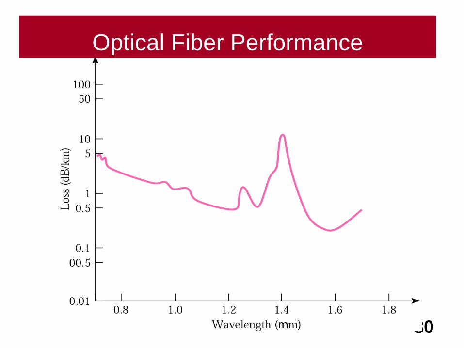
Optical Fiber Performance
How LightTravels Through
Fiber
Propagation Modes81
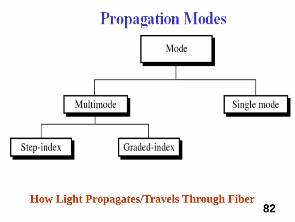
82How Light Propagates/Travels Through Fiber
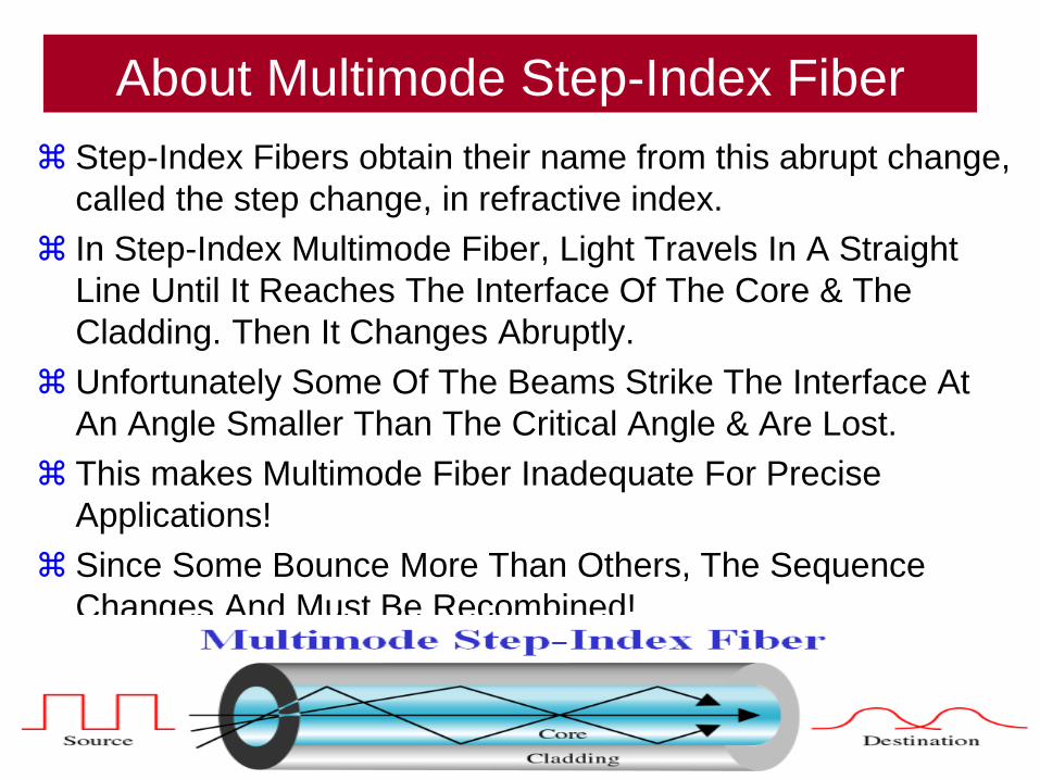
About Multimode Step-Index Fiber
Step-Index Fibers obtain their name from this abrupt change,
called the step change, in refractive index.
In Step-Index Multimode Fiber, Light Travels In A Straight
Line Until It Reaches The Interface Of The Core & The
Cladding. Then It Changes Abruptly.
Unfortunately Some Of The Beams Strike The Interface At
An Angle Smaller Than The Critical Angle & Are Lost.
This makes Multimode Fiber Inadequate For Precise
Applications!
Since Some Bounce More Than Others, The Sequence
Changes And Must Be Recombined!
83
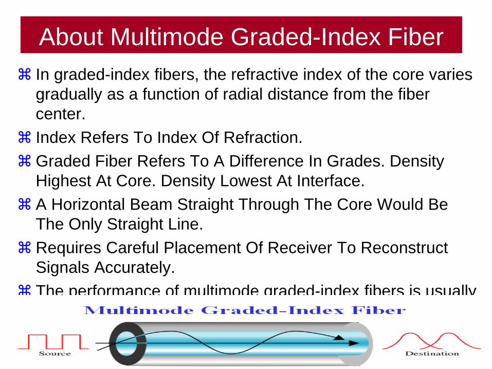
About Multimode Graded-Index Fiber
In graded-index fibers, the refractive index of the core varies
gradually as a function of radial distance from the fiber
center.
Index Refers To Index Of Refraction.
Graded Fiber Refers To A Difference In Grades. Density
Highest At Core. Density Lowest At Interface.
A Horizontal Beam Straight Through The Core Would Be
The Only Straight Line.
Requires Careful Placement Of Receiver To Reconstruct
Signals Accurately.
The performance of multimode graded-index fibers is usually
superior to multimode step-index fibers.
84
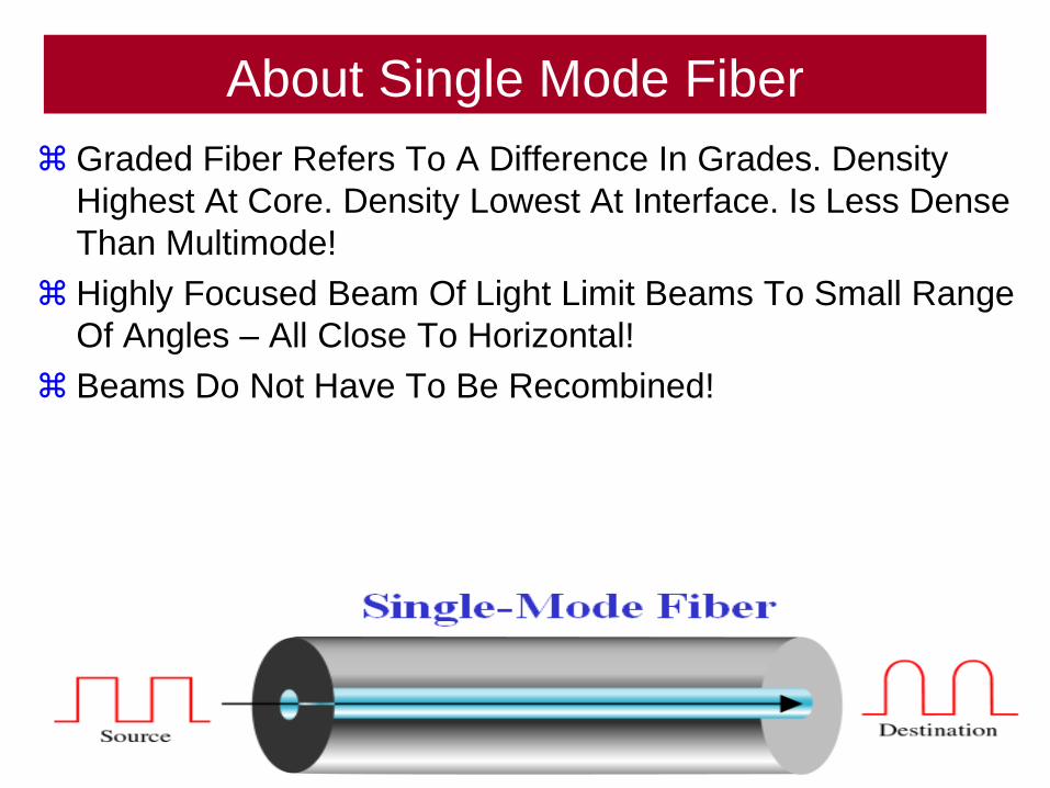
About Single Mode Fiber
Graded Fiber Refers To A Difference In Grades. Density
Highest At Core. Density Lowest At Interface. Is Less Dense
Than Multimode!
Highly Focused Beam Of Light Limit Beams To Small Range
Of Angles – All Close To Horizontal!
Beams Do Not Have To Be Recombined!
85
Light Sources For Fiber Optic
The Fiber Optic Receiving Device Must Have A
Photosensitive Cell Called A Photodiode.
The Fiber Optic Light Source Can Be Light-Emitting Diode
(LED) Or An Injection Laser.
LED’s -Cheaper – Unfocused
Laser – More Expensive – Highly Focused
86

Fiber
Pros & Cons
87
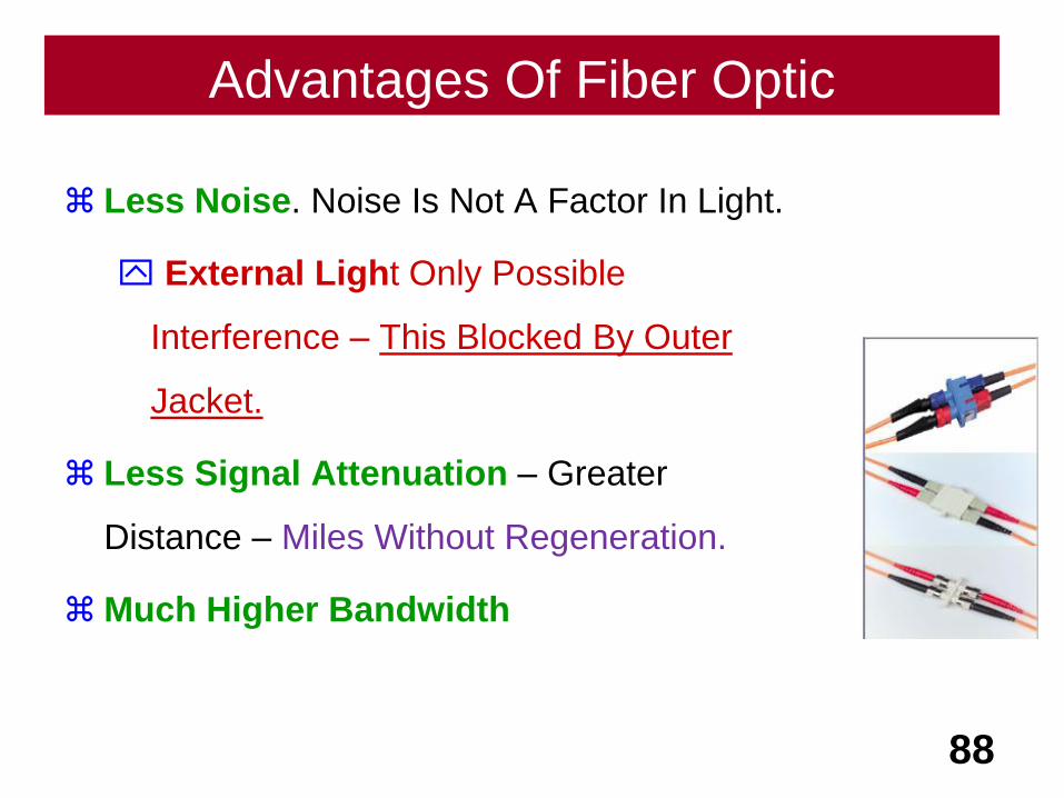
Advantages Of Fiber Optic
Less Noise. Noise Is Not A Factor In Light.
External Light Only Possible
Interference – This Blocked By Outer
Jacket.
Less Signal Attenuation – Greater
Distance – Miles Without Regeneration.
Much Higher Bandwidth
88
Disadvantages Of Fiber Optic
Much More Expensive – Materials Instillation, etc.
Laser Light Source – Can Cost Thousands Of Dollars
Installation Requires Much More Training & Equipment
Fragile - Glass Is More Easily Broken Than Wire.
89
Transmission
90
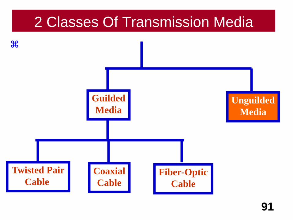
2 Classes Of Transmission Media
91
Guilded
MediaUnguilded
Media
Coaxial
Cable
Twisted Pair
Cable Fiber-Optic
Cable

92
Radio Wave
93
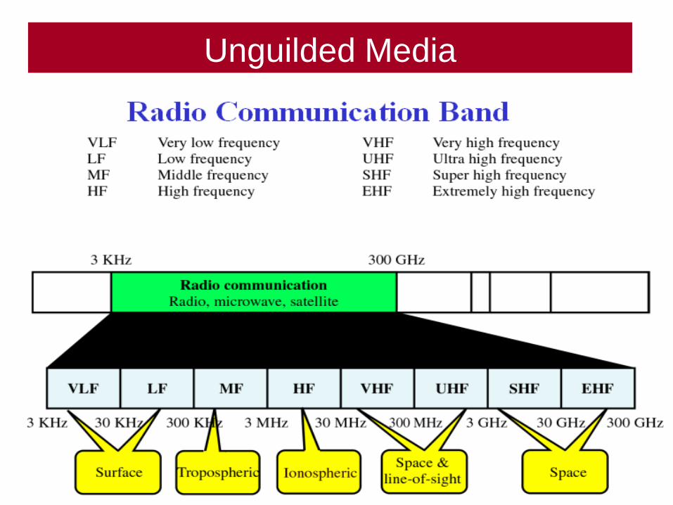
Unguilded Media
94
95
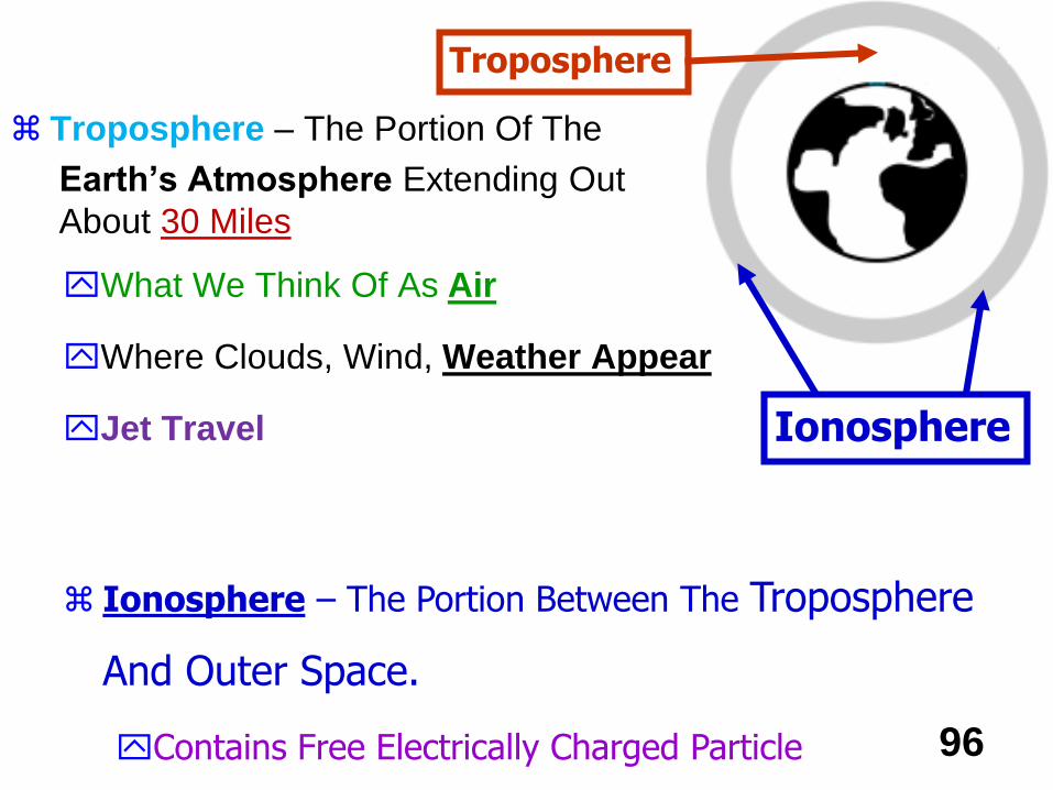
Troposphere – The Portion Of The
Earth’s Atmosphere Extending Out
About 30 Miles
What We Think Of As Air
Where Clouds, Wind, Weather Appear
Jet Travel
96
Ionosphere – The Portion Between The Troposphere
And Outer Space.
Contains Free Electrically Charged Particle
Troposphere
Ionosphere
About Very Low Frequency
Propagation
97
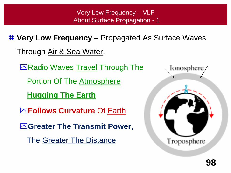
Very Low Frequency – VLF
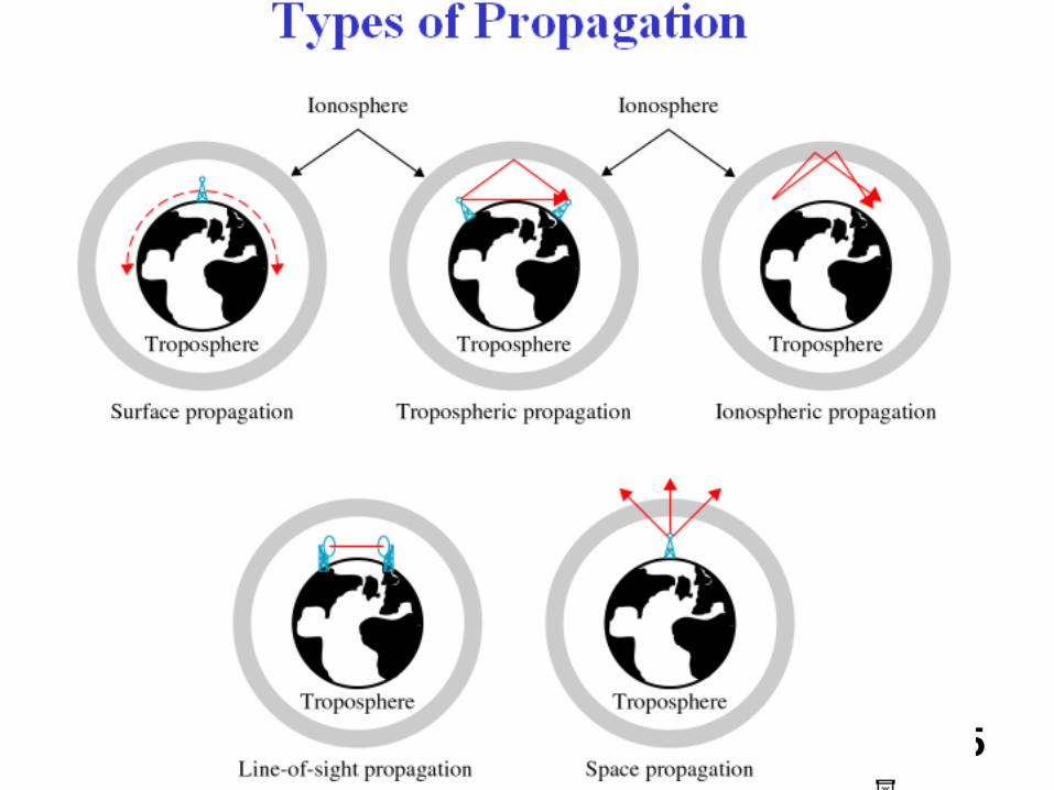
About Surface Propagation - 1
Very Low Frequency – Propagated As Surface Waves
Through Air & Sea Water.
Radio Waves Travel Through The
Portion Of The Atmosphere
Hugging The Earth
Follows Curvature Of Earth
Greater The Transmit Power,
The Greater The Distance
98
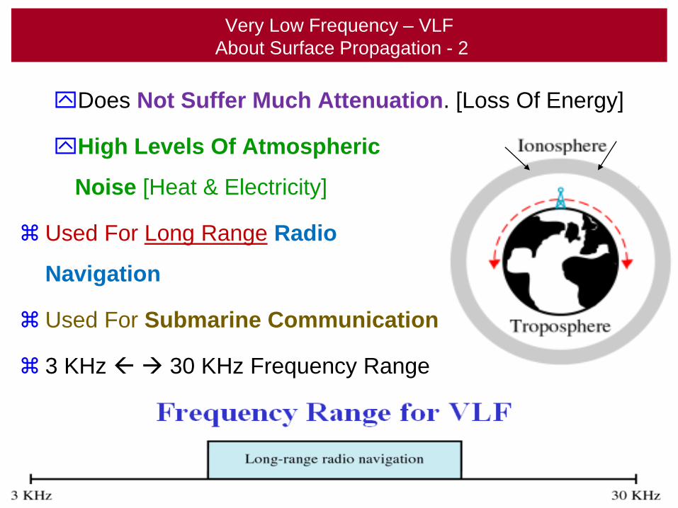
Very Low Frequency – VLF
About Surface Propagation - 2
Does Not Suffer Much Attenuation. [Loss Of Energy]
High Levels Of Atmospheric
Noise [Heat & Electricity]
Used For Long Range Radio
Navigation
Used For Submarine Communication
3 KHz 30 KHz Frequency Range
99
About Low Frequency
Propagation
100
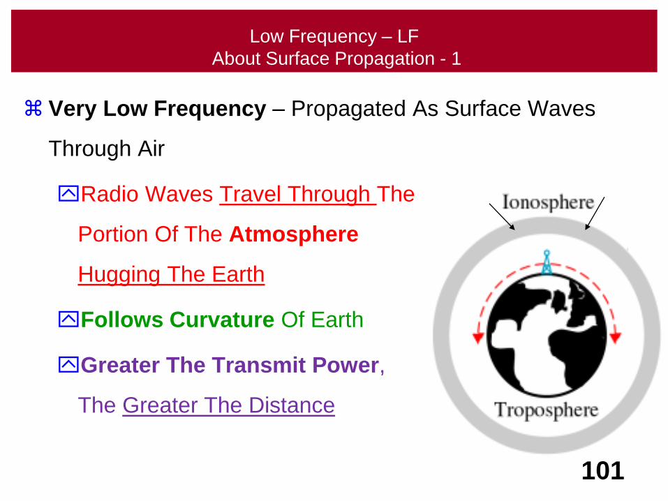
Low Frequency – LF
About Surface Propagation - 1
Very Low Frequency – Propagated As Surface Waves
Through Air
Radio Waves Travel Through The
Portion Of The Atmosphere
Hugging The Earth
Follows Curvature Of Earth
Greater The Transmit Power,
The Greater The Distance
101
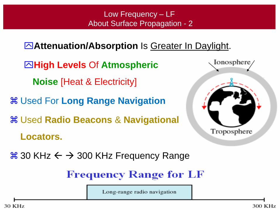
Low Frequency – LF
About Surface Propagation - 2
Attenuation/Absorption Is Greater In Daylight.
High Levels Of Atmospheric
Noise [Heat & Electricity]
Used For Long Range Navigation
Used Radio Beacons & Navigational
Locators.
30 KHz 300 KHz Frequency Range
102
About MiddleFrequency
Propagation
103
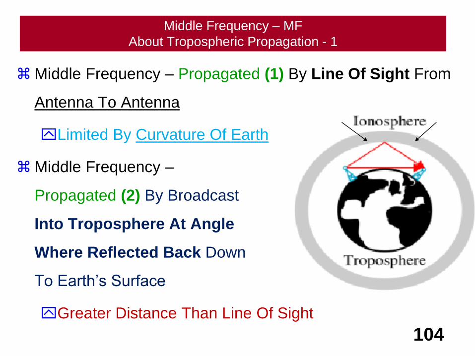
Middle Frequency – MF
About Tropospheric Propagation - 1
Middle Frequency – Propagated (1) By Line Of Sight From
Antenna To Antenna
Limited By Curvature Of Earth
Middle Frequency –
Propagated (2) By Broadcast
Into Troposphere At Angle
Where Reflected Back Down
To Earth’s Surface
Greater Distance Than Line Of Sight
104
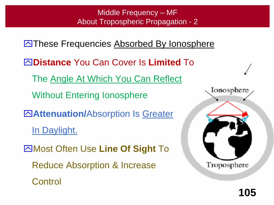
Middle Frequency – MF
About Tropospheric Propagation - 2
These Frequencies Absorbed By Ionosphere
Distance You Can Cover Is Limited To
The Angle At Which You Can Reflect
Without Entering Ionosphere
Attenuation/Absorption Is Greater
In Daylight.
Most Often Use Line Of Sight To
Reduce Absorption & Increase
Control
105
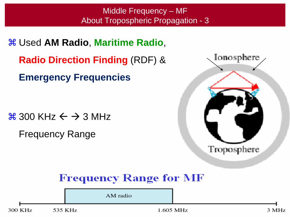
Middle Frequency – MF
About Tropospheric Propagation - 3
Used AM Radio, Maritime Radio,
Radio Direction Finding (RDF) &
Emergency Frequencies
300 KHz 3 MHz
Frequency Range
106
About HighFrequency
Propagation
107
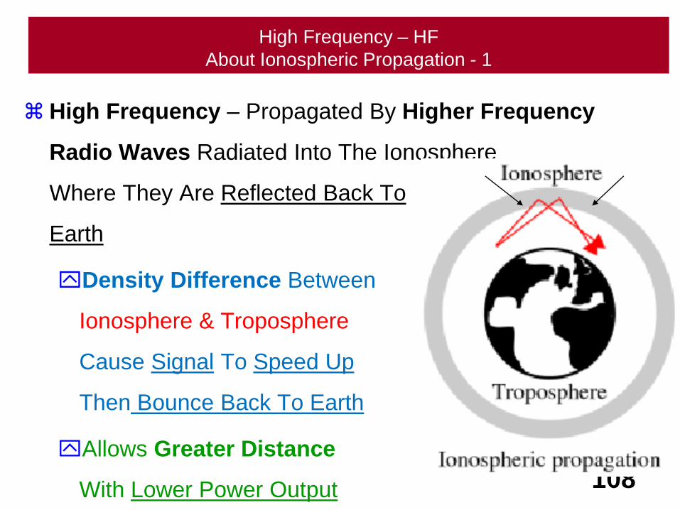
High Frequency – HF
About Ionospheric Propagation - 1
High Frequency – Propagated By Higher Frequency
Radio Waves Radiated Into The Ionosphere
Where They Are Reflected Back To
Earth
Density Difference Between
Ionosphere & Troposphere
Cause Signal To Speed Up
Then Bounce Back To Earth
Allows Greater Distance
With Lower Power Output 108
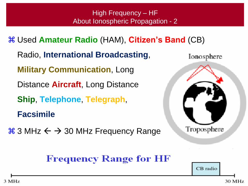
High Frequency – HF
About Ionospheric Propagation - 2
Used Amateur Radio (HAM), Citizen’s Band (CB)
Radio, International Broadcasting,
Military Communication, Long
Distance Aircraft, Long Distance
Ship, Telephone, Telegraph,
Facsimile
3 MHz 30 MHz Frequency Range
109
About VeryHigh Frequency
Propagation
110
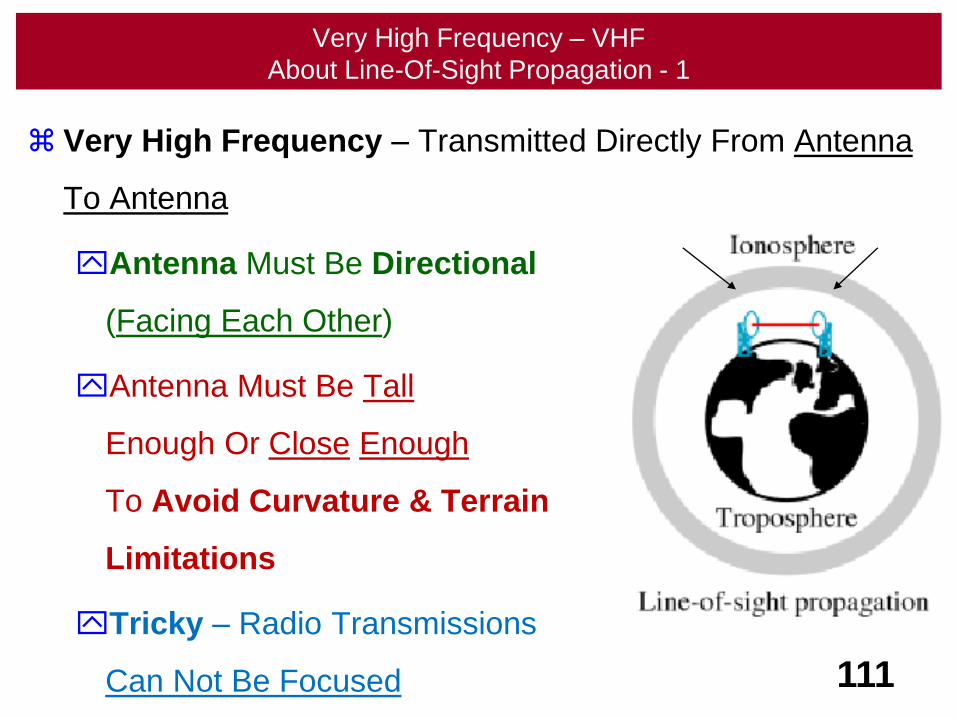
Very High Frequency – VHF
About Line-Of-Sight Propagation - 1
Very High Frequency – Transmitted Directly From Antenna
To Antenna
Antenna Must Be Directional
(Facing Each Other)
Antenna Must Be Tall
Enough Or Close Enough
To Avoid Curvature & Terrain
Limitations
Tricky – Radio Transmissions
Can Not Be Focused 111
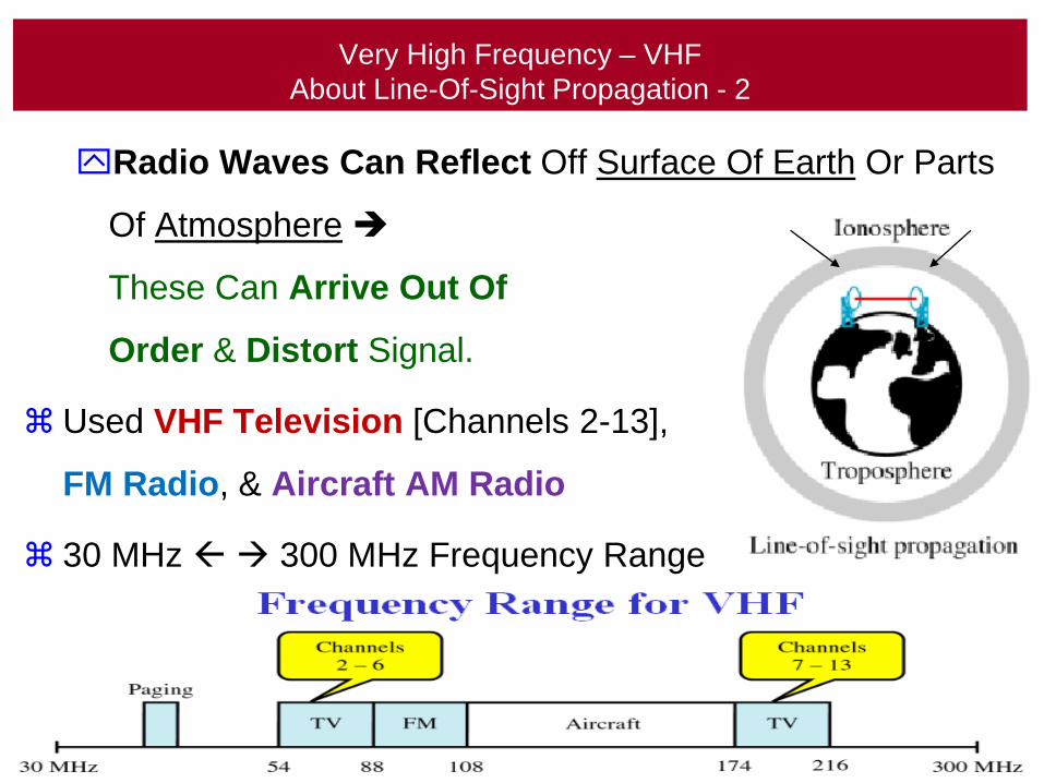
Very High Frequency – VHF
About Line-Of-Sight Propagation - 2
Radio Waves Can Reflect Off Surface Of Earth Or Parts
Of Atmosphere
These Can Arrive Out Of
Order & Distort Signal.
Used VHF Television [Channels 2-13],
FM Radio, & Aircraft AM Radio
30 MHz 300 MHz Frequency Range
112

About UltraHigh Frequency
Propagation
113
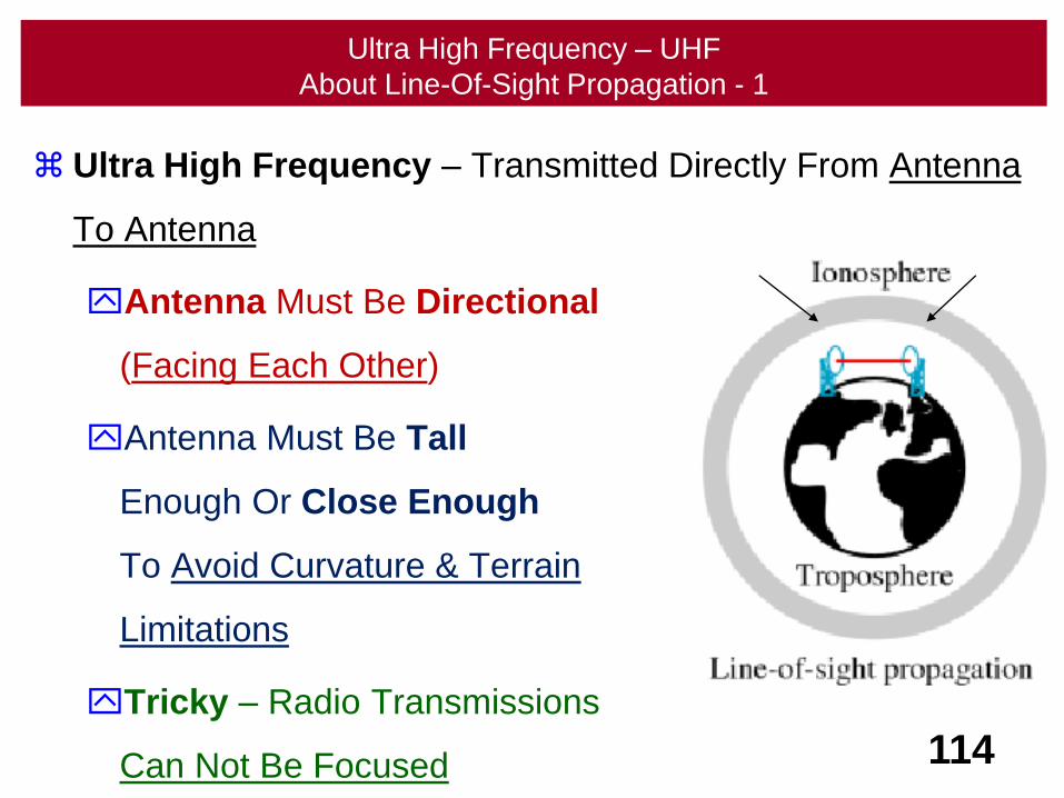
Ultra High Frequency – UHF
About Line-Of-Sight Propagation - 1
Ultra High Frequency – Transmitted Directly From Antenna
To Antenna
Antenna Must Be Directional
(Facing Each Other)
Antenna Must Be Tall
Enough Or Close Enough
To Avoid Curvature & Terrain
Limitations
Tricky – Radio Transmissions
Can Not Be Focused 114
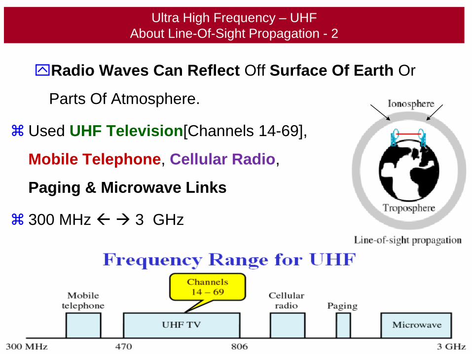
Ultra High Frequency – UHF
About Line-Of-Sight Propagation - 2
Radio Waves Can Reflect Off Surface Of Earth Or
Parts Of Atmosphere.
Used UHF Television[Channels 14-69],
Mobile Telephone, Cellular Radio,
Paging & Microwave Links
300 MHz 3 GHz
Frequency Range
115
About SuperHigh Frequency
Propagation
116
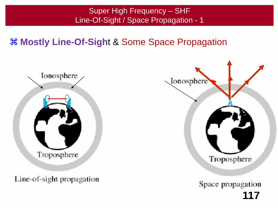
Super High Frequency – SHF
Line-Of-Sight / Space Propagation - 1
Mostly Line-Of-Sight & Some Space Propagation
117
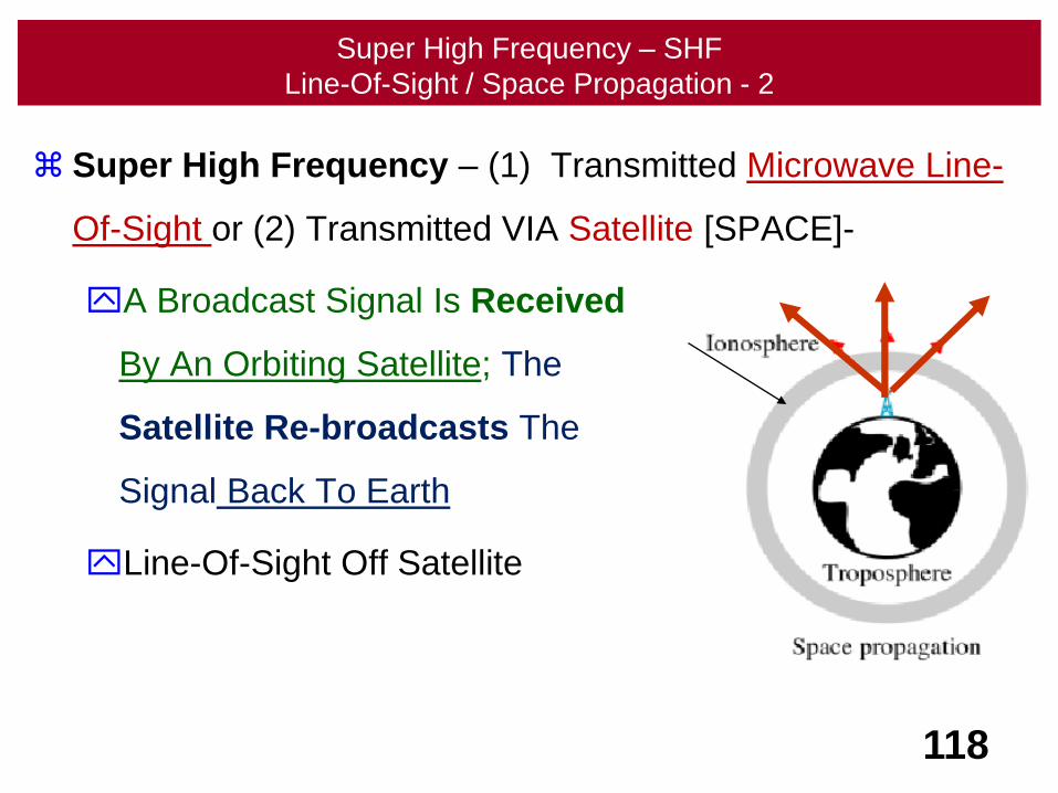
Super High Frequency – SHF
Line-Of-Sight / Space Propagation - 2
Super High Frequency – (1) Transmitted Microwave Line-
Of-Sight or (2) Transmitted VIA Satellite [SPACE]-
A Broadcast Signal Is Received
By An Orbiting Satellite; The
Satellite Re-broadcasts The
Signal Back To Earth
Line-Of-Sight Off Satellite
118
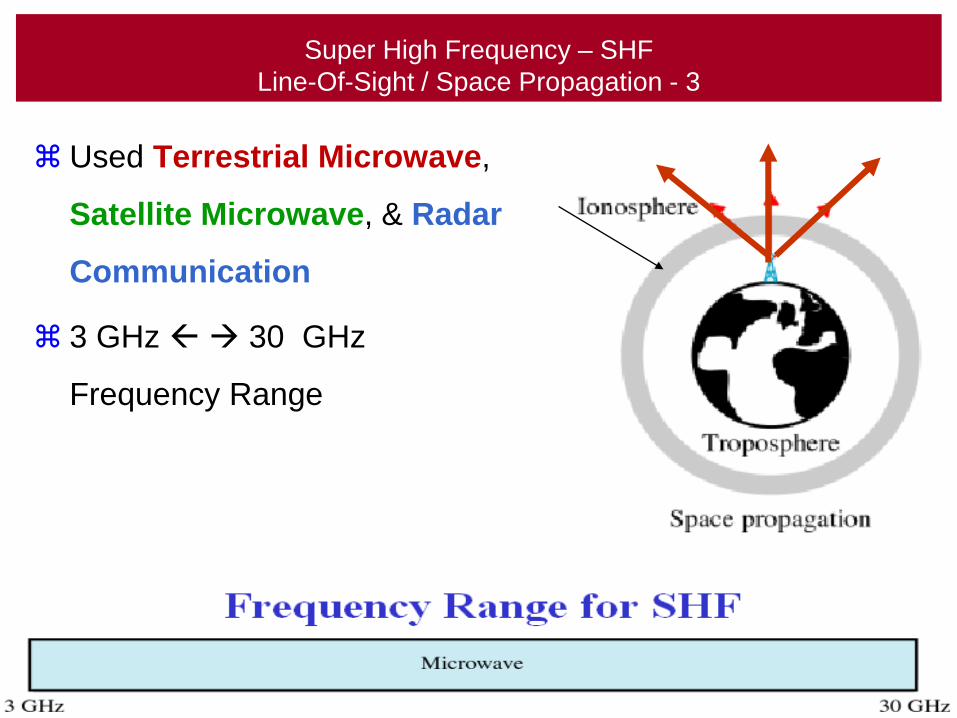
Super High Frequency – SHF
Line-Of-Sight / Space Propagation - 3
Used Terrestrial Microwave,
Satellite Microwave, & Radar
Communication
3 GHz 30 GHz
Frequency Range
119
About ExtremelyHigh Frequency
Propagation
120
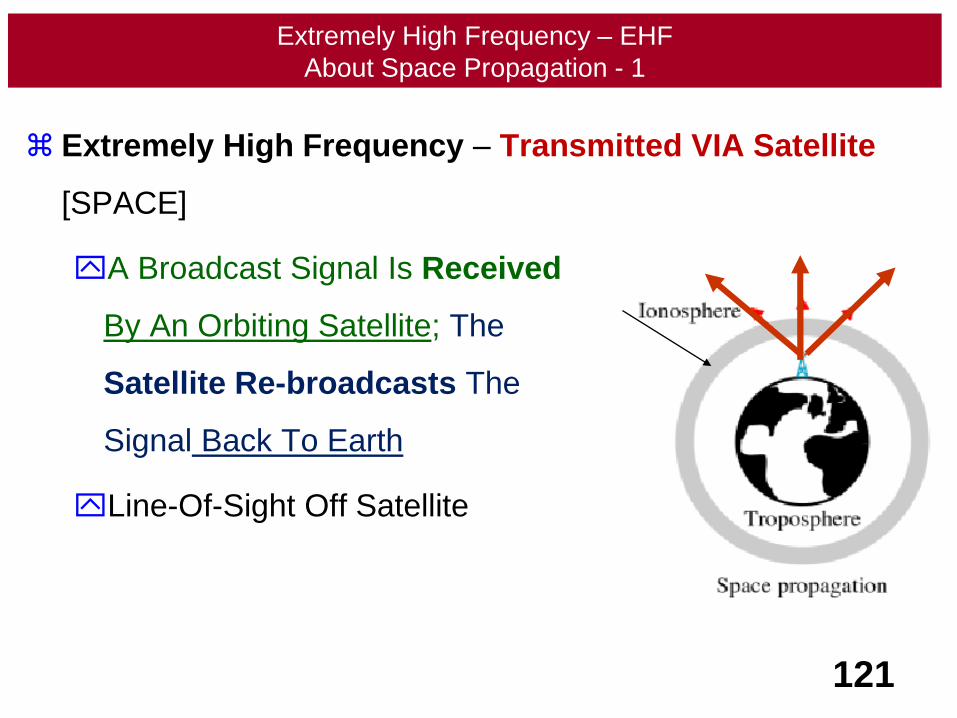
Extremely High Frequency – EHF
About Space Propagation - 1
Extremely High Frequency – Transmitted VIA Satellite
[SPACE]
A Broadcast Signal Is Received
By An Orbiting Satellite; The
Satellite Re-broadcasts The
Signal Back To Earth
Line-Of-Sight Off Satellite
121

Extremely High Frequency – EHF
About Space Propagation - 2
Microwave Used In Scientific
Applications & Research
Radar, Satellite, &
Experimental Communications
30 GHz 300 GHz
Frequency Range
122
Propagation
Summary
123
124
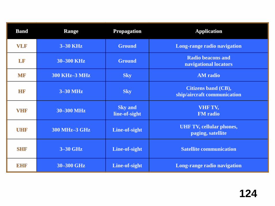
Band Range Propagation Application
VLF 3–30 KHz Ground Long-range radio navigation
LF 30–300 KHz GroundRadio beacons and
navigational locators
MF 300 KHz–3 MHz Sky AM radio
HF 3–30 MHz SkyCitizens band (CB),
ship/aircraft communication
VHF 30–300 MHzSky and
line-of-sight
VHF TV,
FM radio
UHF 300 MHz–3 GHz Line-of-sightUHF TV, cellular phones,
paging, satellite
SHF 3–30 GHz Line-of-sight Satellite communication
EHF 30–300 GHz Line-of-sight Long-range radio navigation
OmnidirectionalAntenna
125
126
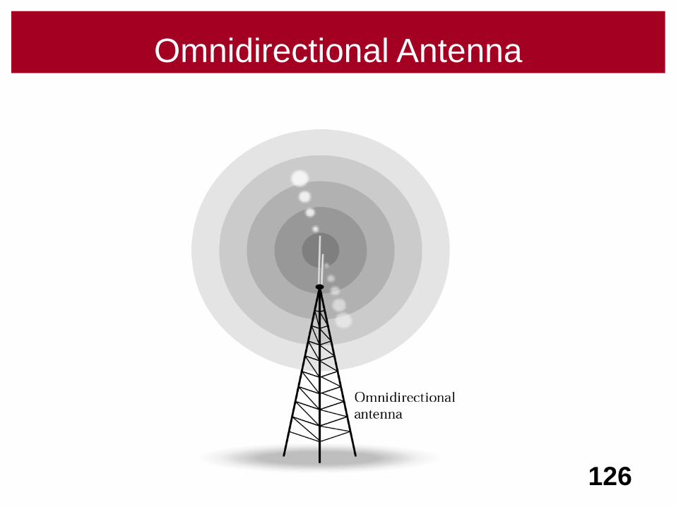
Omnidirectional Antenna
Terrestrial
Microwave
127
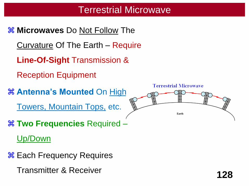
Terrestrial Microwave
Microwaves Do Not Follow The
Curvature Of The Earth – Require
Line-Of-Sight Transmission &
Reception Equipment
Antenna’s Mounted On High
Towers, Mountain Tops, etc.
Two Frequencies Required –
Up/Down
Each Frequency Requires
Transmitter & Receiver128
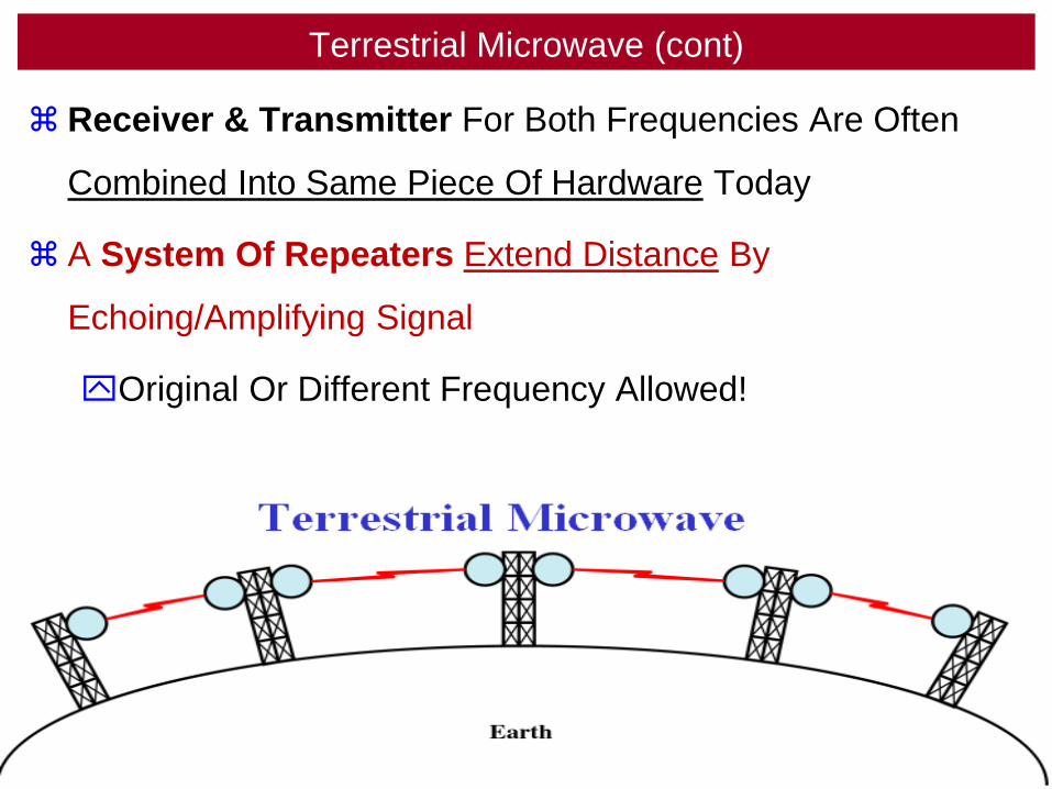
Terrestrial Microwave (cont)
Receiver & Transmitter For Both Frequencies Are Often
Combined Into Same Piece Of Hardware Today
A System Of Repeaters Extend Distance By
Echoing/Amplifying Signal
Original Or Different Frequency Allowed!
129
Microwave
Antenna
130
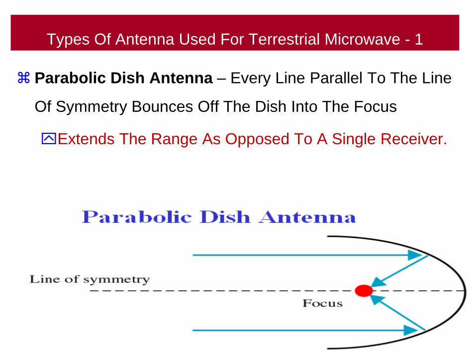
Types Of Antenna Used For Terrestrial Microwave - 1
Parabolic Dish Antenna – Every Line Parallel To The Line
Of Symmetry Bounces Off The Dish Into The Focus
Extends The Range As Opposed To A Single Receiver.
131
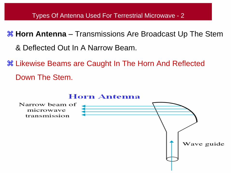
Types Of Antenna Used For Terrestrial Microwave - 2
Horn Antenna – Transmissions Are Broadcast Up The Stem
& Deflected Out In A Narrow Beam.
Likewise Beams are Caught In The Horn And Reflected
Down The Stem.
132
Satellite Communication
133
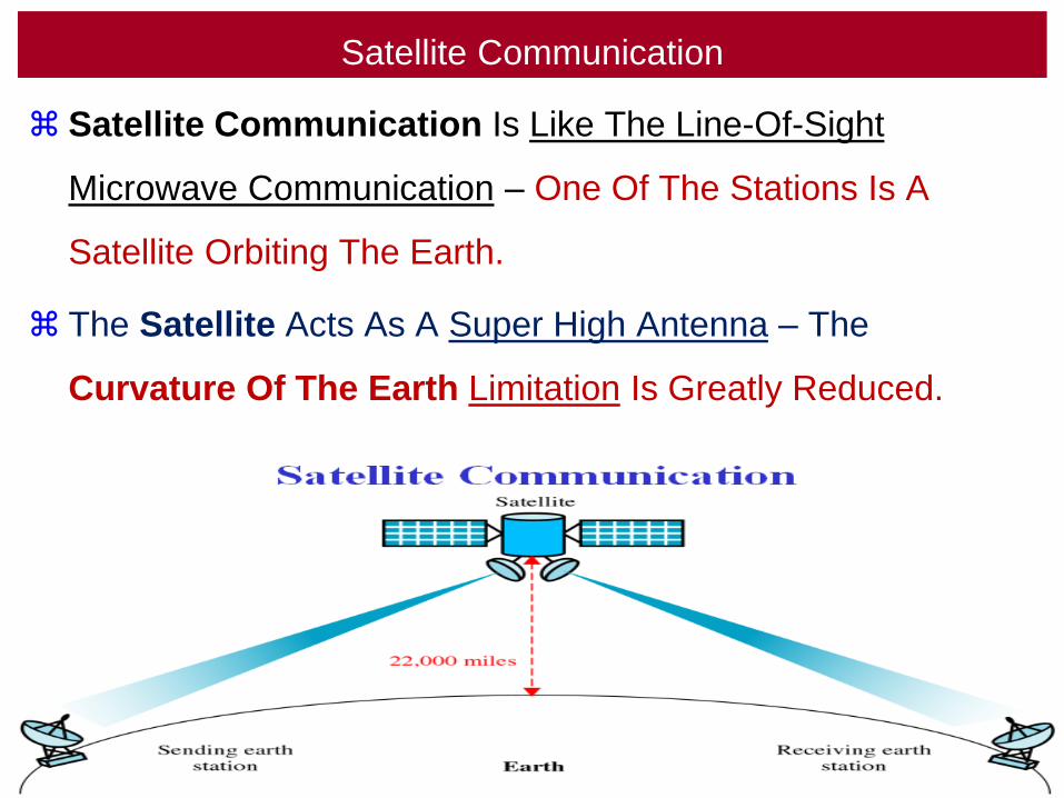
Satellite Communication
Satellite Communication Is Like The Line-Of-Sight
Microwave Communication – One Of The Stations Is A
Satellite Orbiting The Earth.
The Satellite Acts As A Super High Antenna – The
Curvature Of The Earth Limitation Is Greatly Reduced.
134
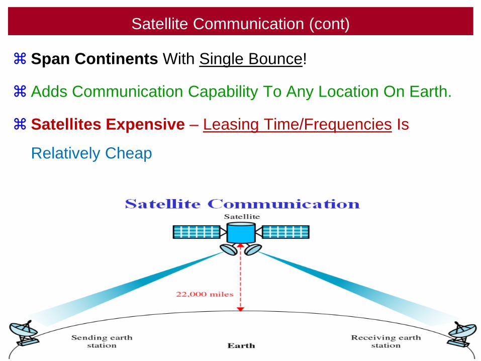
Satellite Communication (cont)
Span Continents With Single Bounce!
Adds Communication Capability To Any Location On Earth.
Satellites Expensive – Leasing Time/Frequencies Is
Relatively Cheap
135
GeosynchronousSatellites
136
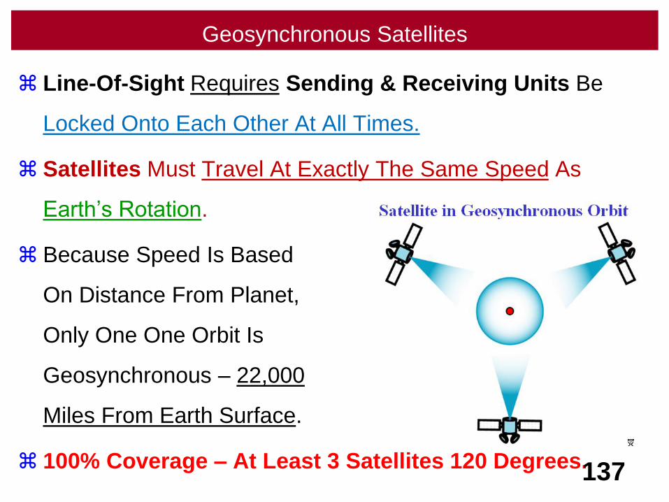
Geosynchronous Satellites
Line-Of-Sight Requires Sending & Receiving Units Be
Locked Onto Each Other At All Times.
Satellites Must Travel At Exactly The Same Speed As
Earth’s Rotation.
Because Speed Is Based
On Distance From Planet,
Only One One Orbit Is
Geosynchronous – 22,000
Miles From Earth Surface.
100% Coverage – At Least 3 Satellites 120 Degrees.137
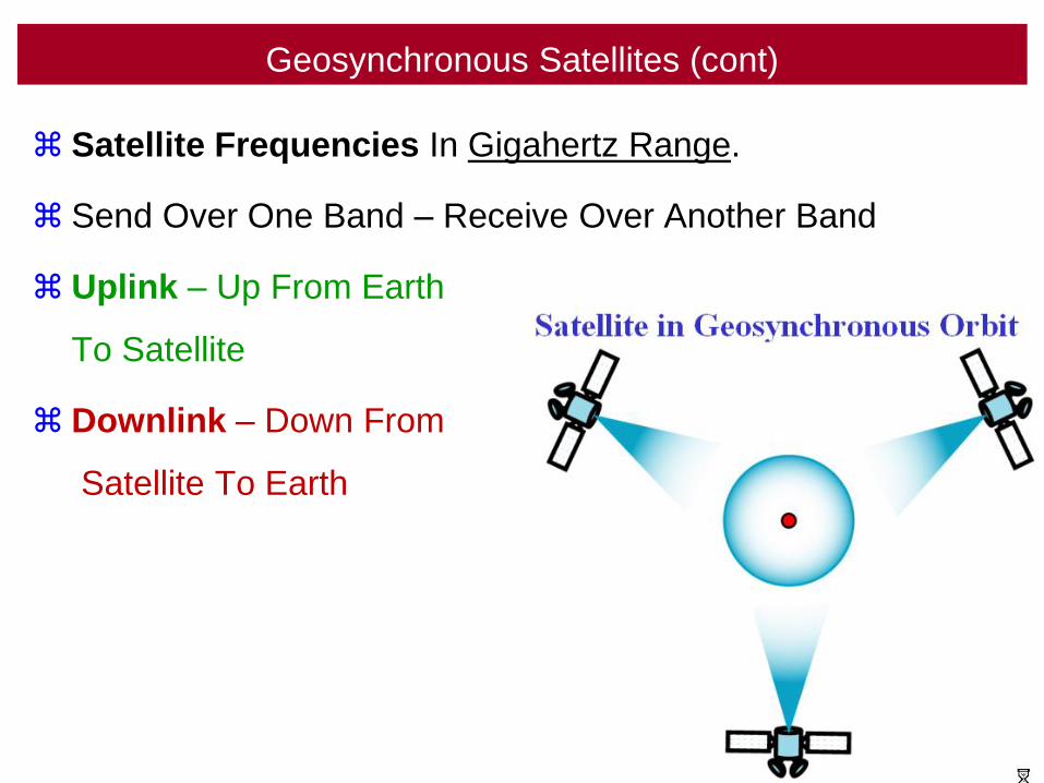
Geosynchronous Satellites (cont)
Satellite Frequencies In Gigahertz Range.
Send Over One Band – Receive Over Another Band
Uplink – Up From Earth
To Satellite
Downlink – Down From
Satellite To Earth
138
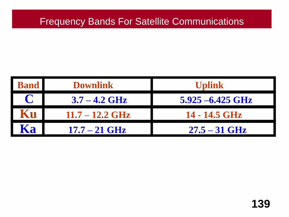
Frequency Bands For Satellite Communications
139
Ka 17.7 – 21 GHz 27.5 – 31 GHz
Ku 11.7 – 12.2 GHz 14 - 14.5 GHz
C 3.7 – 4.2 GHz 5.925 –6.425 GHz
Band Downlink Uplink
Microwave UseIn Cell Phones
140
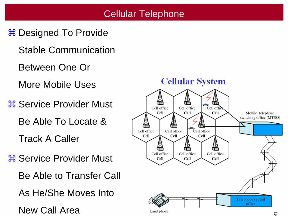
Cellular Telephone
Designed To Provide
Stable Communication
Between One Or
More Mobile Uses
Service Provider Must
Be Able To Locate &
Track A Caller
Service Provider Must
Be Able to Transfer Caller
As He/She Moves Into
New Call Area 141
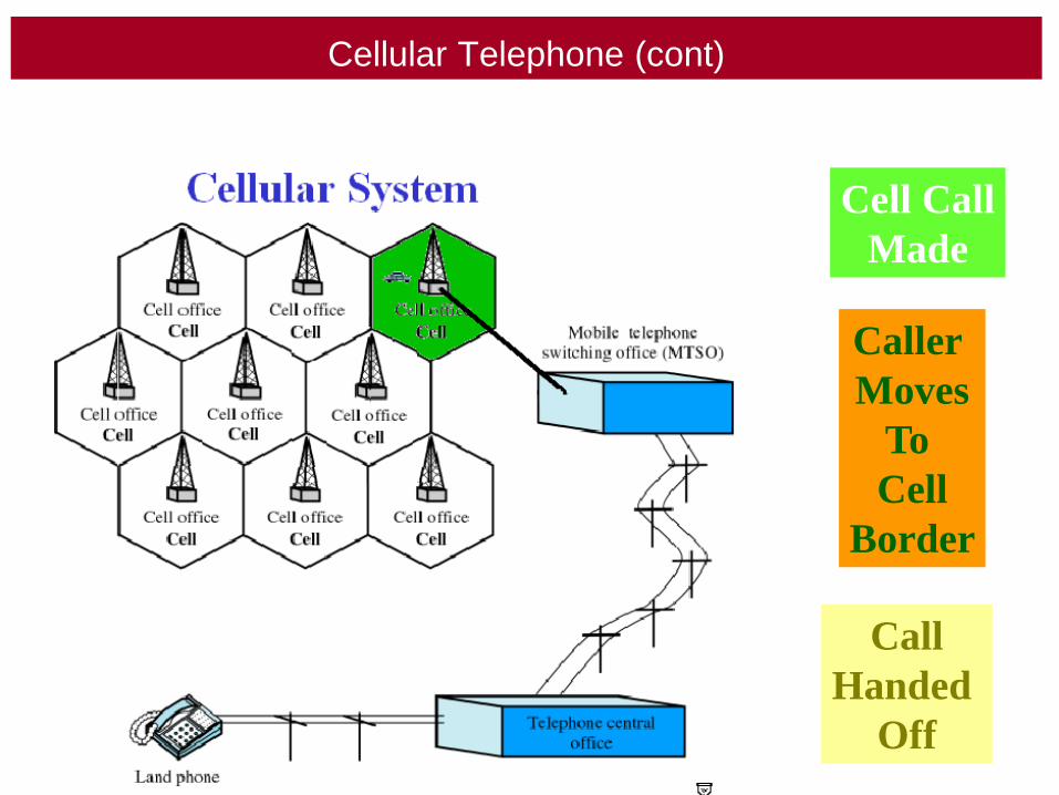
Cellular Telephone (cont)
142
Cell Call
Made
Caller
Moves
To
Cell
Border
Call
Handed
Off
About Cellular Telephone
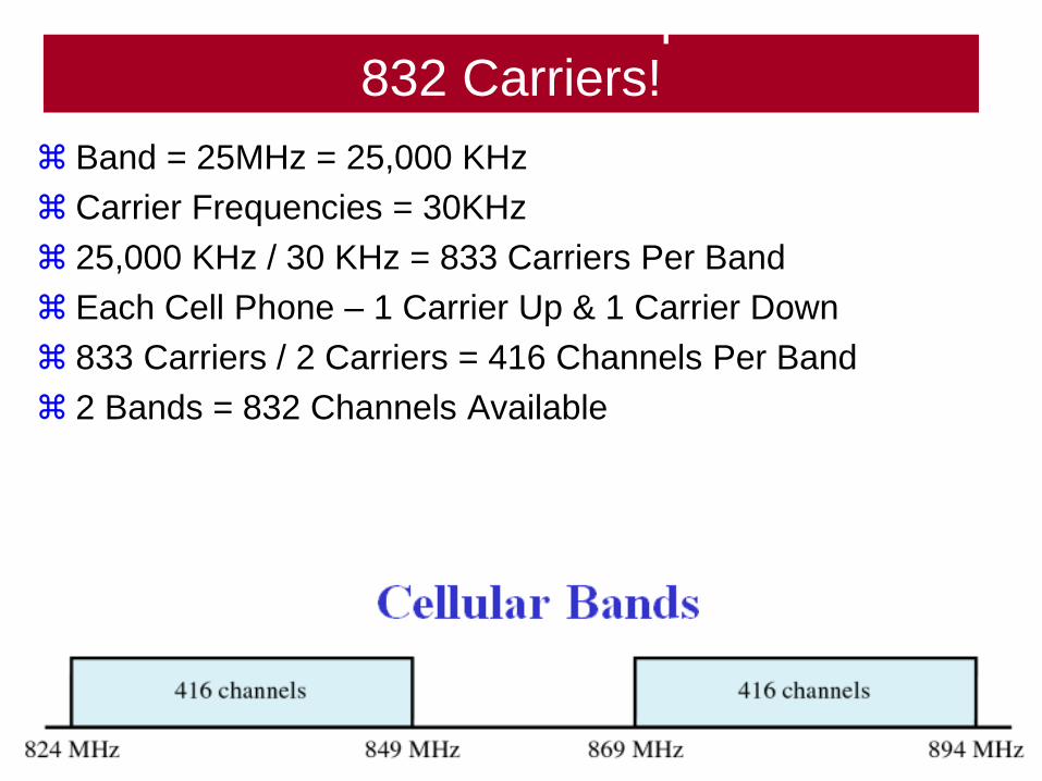
832 Carriers!
Band = 25MHz = 25,000 KHz
Carrier Frequencies = 30KHz
25,000 KHz / 30 KHz = 833 Carriers Per Band
Each Cell Phone – 1 Carrier Up & 1 Carrier Down
833 Carriers / 2 Carriers = 416 Channels Per Band
2 Bands = 832 Channels Available
143
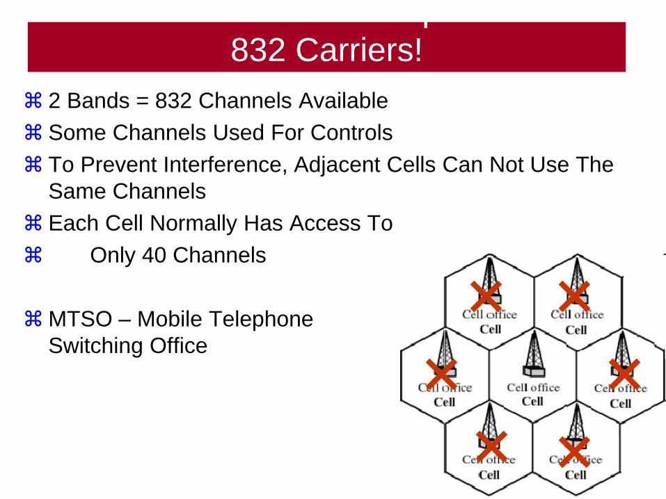
About Cellular Telephone
832 Carriers!
2 Bands = 832 Channels Available
Some Channels Used For Controls
To Prevent Interference, Adjacent Cells Can Not Use The
Same Channels
Each Cell Normally Has Access To
Only 40 Channels
MTSO – Mobile Telephone
Switching Office
144
Microwave UseIn Wireless LANs
145
Inferared
146

Infrared
Short Range Communication
High Frequencies
Can't Penetrate Walls
Sun's Waves Interfere With It
Remotes! Wireless Keyboards! Wireless Mice!
147
Impairment
Revisited
148

Transmission Impairment
149
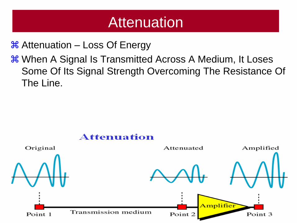
Attenuation
Attenuation – Loss Of Energy
When A Signal Is Transmitted Across A Medium, It Loses
Some Of Its Signal Strength Overcoming The Resistance Of
The Line.
150
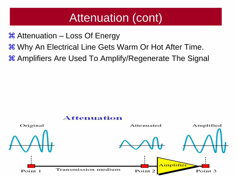
Attenuation (cont)
Attenuation – Loss Of Energy
Why An Electrical Line Gets Warm Or Hot After Time.
Amplifiers Are Used To Amplify/Regenerate The Signal
151

Distortion
Distortion Means The Signal Changes Shape.
152
Noise
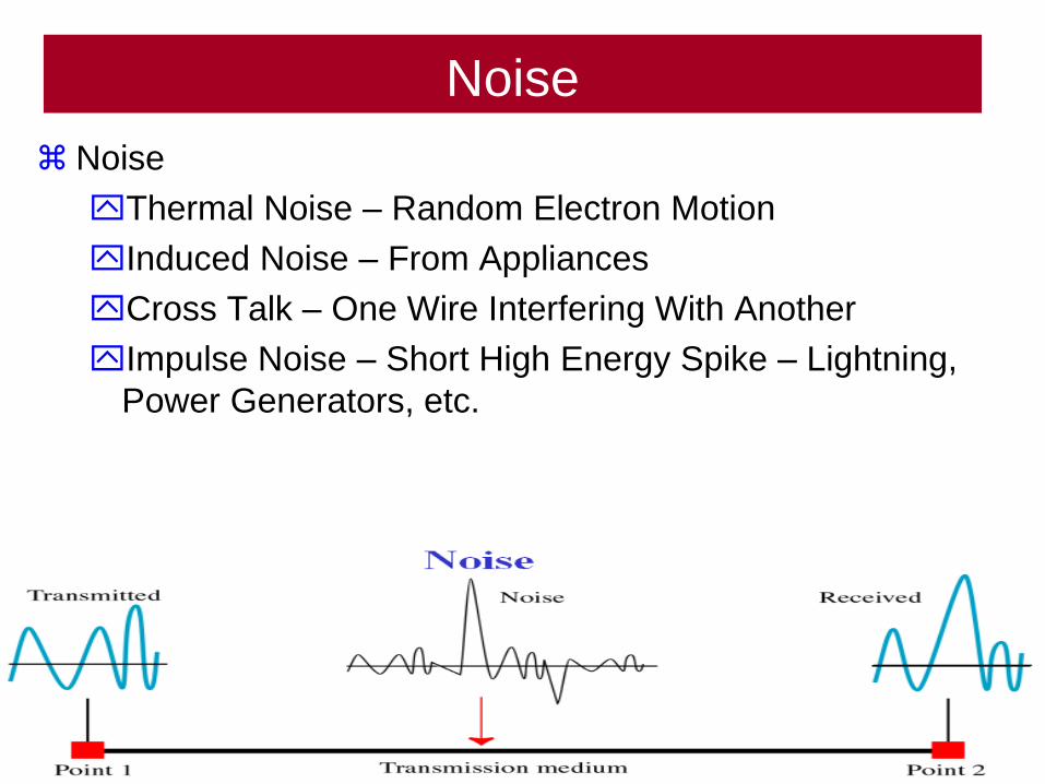
Noise
Thermal Noise – Random Electron Motion
Induced Noise – From Appliances
Cross Talk – One Wire Interfering With Another
Impulse Noise – Short High Energy Spike – Lightning,
Power Generators, etc.
153

Summary
154
155
Radio waves are used
for multicast
communications, such as
radio and television, and
paging systems.
Note:

156
Microwaves are used for
unicast communication such
as cellular telephones,
satellite networks, and
wireless LANs.
Note:
157
Infrared signals can be
used for short-range
communication in a closed
area using line-of-sight
propagation such as remote
controls.
Note:
The Network Administrator Must
Consider Many Things
158
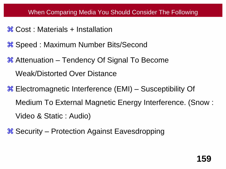
When Comparing Media You Should Consider The Following
Cost : Materials + Installation
Speed : Maximum Number Bits/Second
Attenuation – Tendency Of Signal To Become
Weak/Distorted Over Distance
Electromagnetic Interference (EMI) – Susceptibility Of
Medium To External Magnetic Energy Interference. (Snow :
Video & Static : Audio)
Security – Protection Against Eavesdropping
159
160
Data Communications & Networking
CSCI 3342
Dr. Thomas E. HicksComputer Science Department
Trinity University
Textbook: Computer Networks
By Andrew Tanenbaum
Textbook: Data Communications & Networking
By Behrouz Forouzan
Special Thanks To WCB/McGraw-Hill For Providing
Graphics For
Many Text Book Figures For Use In This Presentation.


![Day and night[3342]](https://img.pdfslide.net/doc/110x75/5a64a6b27f8b9a8e568b4ff5/day-and-night3342.jpg)