Embed Size (px)
Citation preview
DATA ITEM DESCRIPTION Title: AEROSPACE EMERGENCY RESCUE AND MISHAP RESPONSE INFORMATION (EMERGENCY SERVICES) SOURCE DATA Number: DI-TMSS-81532C Approval Date: 20130227 AMSC Number: F9336 Limitation: DTIC Applicable: GIDEP Applicable: Office of Primary Responsibility: 10 (AFCEC/CXF) Applicable Forms: Use/relationship: This information is used as source data for the preparation and maintenance of Technical Order (TO) 00-105E-9, Aerospace Emergency Rescue and Mishap Response Information (Emergency Services). This DID contains the format and content preparation instructions for the data product generated by the specific and discrete task requirement as delineated in the contract. Additionally, required changes for text and illustrations are explained. a. This DID is applicable to the acquisition and modification of all aircraft, helicopters, unmanned aircraft vehicles (UAV) and aircraft systems that are to be used by the Department of Defense military services and require fire protection and emergency rescue information to include NASA, Civil Reserve Air Fleet, and various US Government agency aircraft. b. TO 00-105E-9 is primarily used by firefighting personnel to identify internal and external hazards/HAZMAT, gain entry, shutdown systems, and rescue aircrew and passengers in the event of an aircraft accident. It is additionally utilized by secondary response situations confronted by Bioenvironmental engineers, accident investigation teams, secondary emergency responders, explosive ordnance disposal (EOD) and aircraft crash recovery crews in the performance of their duties. c. The procedures and methodologies in the TO are used by Fire Department aircraft fire fighting training programs for installation assigned aircraft. d. This DID supercedes DI-TMSS-81532A, Aerospace Emergency Rescue and Mishap Response Information (Emergency Services) Source Data, dated 20060905. Source data labeling, government client and Special Program Managers responsibilities are addressed making this revision necessary bringing it in line with its current use and methodologies. Requirements:
1. Reference Documents. The applicable issue of the documents cited herein, including their approval dates and dates of any applicable amendments, notices, and revisions, shall be as specified in the contract. 2. Format. Source Data contractor format is acceptable. There will be no ITAR labels, Proprietary statements, or information prohibiting public release attached to the source data. This data will be routed to a designated government client and the Special Program Office providing the source data is the approving authority authorizing the release of information by letter. Abbreviations and acronyms shall be kept to a minimum and be in accordance with MIL-STD-38784. MIL-STD-38784 may be obtained from the Standardization Documents Order Clerk, 700 Robbins Avenue, Building 4D, Philadelphia, PA 19111-5094. 3. Content. The content of the information shall be presented in the style of the technical manual specified in the contract. Text is typewritten and single spaced. Illustrations shall be presented in textual descriptive form, marked-up illustrations, marked-up photographs, or existing TM drawings with appropriate text describing intent of drawing. 3.1 Preparation Instructions. The source data shall include the following:
1
Downloaded from http://www.everyspec.com
DI-TMSS-81532C Item 3.1 PREPARATION INSTRUCTIONS (Continued) 3.1.1 System Coverage. All aircraft, helicopters, UAVs, or aircraft systems that are to be used by the Department of Defense and require fire protection and emergency rescue. 3.1.2 Illustrations. (See figures 1 - 13) Illustrations needed in conjunction with this data are extracted from existing Technical Manuals (TM) or engineering drawings that are developed for the aircraft or system being acquired. Digital photographs are also acceptable. Illustrations are created only when existing illustrations, found in the relevant TMs and engineering drawings, cannot satisfy the requirements of this DID. The following apply to illustrations:
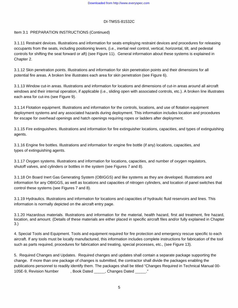
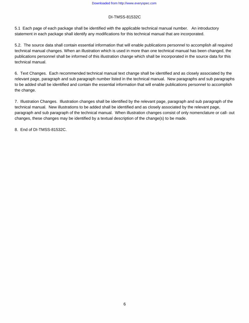
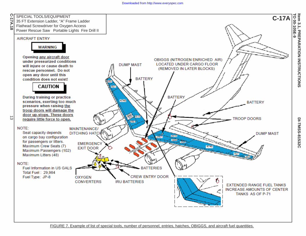
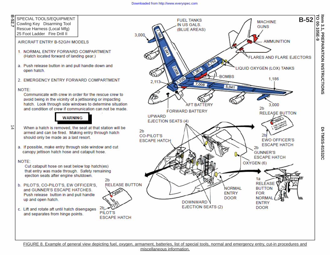
a. Illustrations are in accordance with MIL-STD-38784 with the exception that they do not have figure numbers and color is used as described in 3.1.3. b. Illustrations are turned 90 degrees counterclockwise (landscape - see all figures). c. Each type and model aircraft is orientated to a computer screen instead of a standard left-hand page. d. This manual is prepared in electronic media and is published in PDF format posted to an authorized web site. e. The official military or commercial aircraft designations, such as F-22A, F-117A, C-17, and B-2, are positioned in the upper right corner. f. The page number at the upper left is rotated 90 degrees clockwise and is associated with the aircraft such as C-17.1, B-2.9, and F-15.4. g. A list of special tools and equipment required is boxed in the upper left corner of the Aircraft Entry page of each type and model of aircraft (see Figures 7 and 8). h. Aircraft entry and model designation (such as C-17A, B-52) is as depicted (see Figures 7 and 8). i. Illustrations are coordinated with text by showing applicable paragraph numbers (see Figure 8). j. Aircraft dimensions, height, length, and wingspan, are depicted in a 3 view graphic (see Figure 2). k. Aircraft recognition is illustrated by an Aircraft Paint Scheme page with a current picture of the aircraft (see Figure 1). 3.1.3 Color in illustrations. Other colors may be used to prevent confusion when areas overlap or a unique system or component is used. The following items are depicted on appropriate illustrations and are colored using the following guidelines: a. Fuel systems - blue. b. Oxygen systems and cut-in areas - yellow. c. Armament (interior and exterior) - red. d. Battery (main and auxiliaries) - black.
2
Downloaded from http://www.everyspec.com
DI-TMSS-81532C
Item 3.1 PREPARATION INSTRUCTIONS (Continued) e. Hydrazine - purple. f. Nitrogen systems - orange. g. Ammonia - green. h. Hydraulic systems - brown. i. Oil and reservoirs - light brown j. Composites materials - various (with legend) k. Emergency and normal entry details: (1) Emergency releases (interior and exterior) - red. (2) Ejection handgrips - red.
(3) Jettison handles (canopies, doors, and hatches) - red. (4) Ejection catapult safety pins with streamers - red. NOTE: These details may also be red/black or yellow/black showing actual colors. l. Engine shutdown details: (1) Fire shutdown switches - red. (2) Fire suppression systemT-handles - red. (3) Power and battery switches - red. (4) Throttle levers - red. (5) Fuel selector switches - red. (6) Mixture levers - red. (7) Auxiliary Power Unit (APU) switches - red. m. Ejection seat details: (1) Firing handles/triggers - red. (2) Arming levers - red. (3) Safety pins and streamers - red.
3
Downloaded from http://www.everyspec.com
DI-TMSS-81532C
Item 3.1 PREPARATION INSTRUCTIONS (Continued)
(4) Initiators, thermal batteries, pyrotechnic devices, and shield mild detonating cord - red. (5) Rocket catapult and other seat mounted rockets - red.
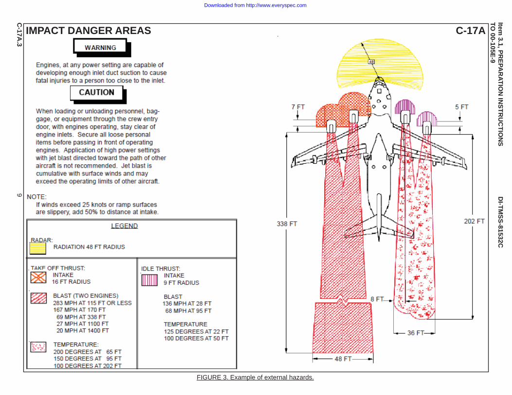
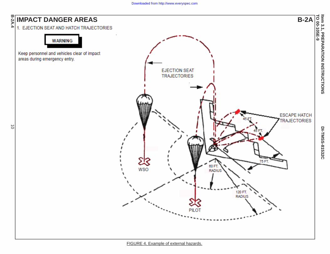
(6) Initiator hose quick disconnects - red. n. Aircrew extraction details: (1) Restraint belts - red. (2) Releases for restraint belts, harnesses, straps and handles, survival kits - red. (3) Personal service quick disconnects - red. o. Skin penetration point/fire access door details: (1) Skin penetration - red or broken red line (2) Fire access doors - red or broken red line 3.1.4 External hazards. (see Figures 3 and 4) Illustrations and information for all external hazards such as emitting radar zones, approach areas to engine intakes and exhausts, propeller clearances, ejected seat and jettisoned canopy envelopes with associated shrapnel danger areas, spin and drag chute ignitors or cartridges, armament firing zones, hot brakes, engine starting cartridges, APU exhaust ports, flare tube outlets, chaff dispensing units, etc. These areas are depicted as a shaded area or with broken lines. 3.1.5 Fuel system (internal hazards). Illustrations and information for fuel systems, including fuel tanks, that are internally hazardous such as interconnecting lines with fuel tanks, etc., (see Figures 7 and 8).
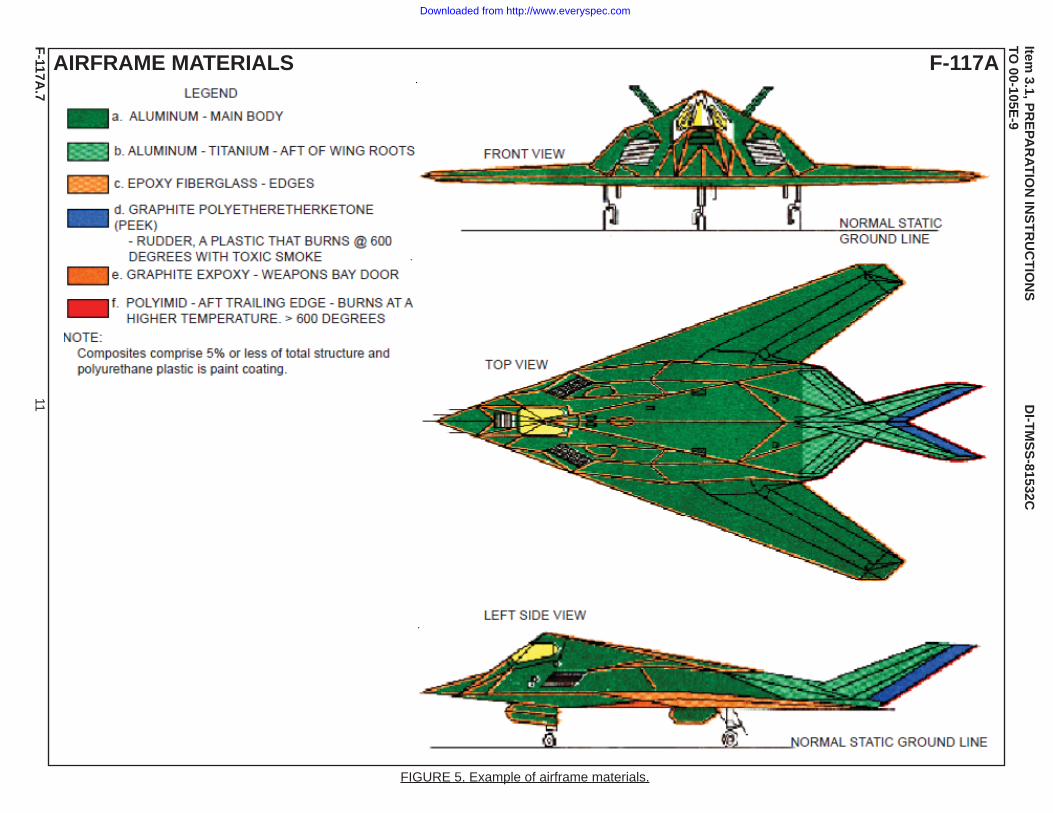
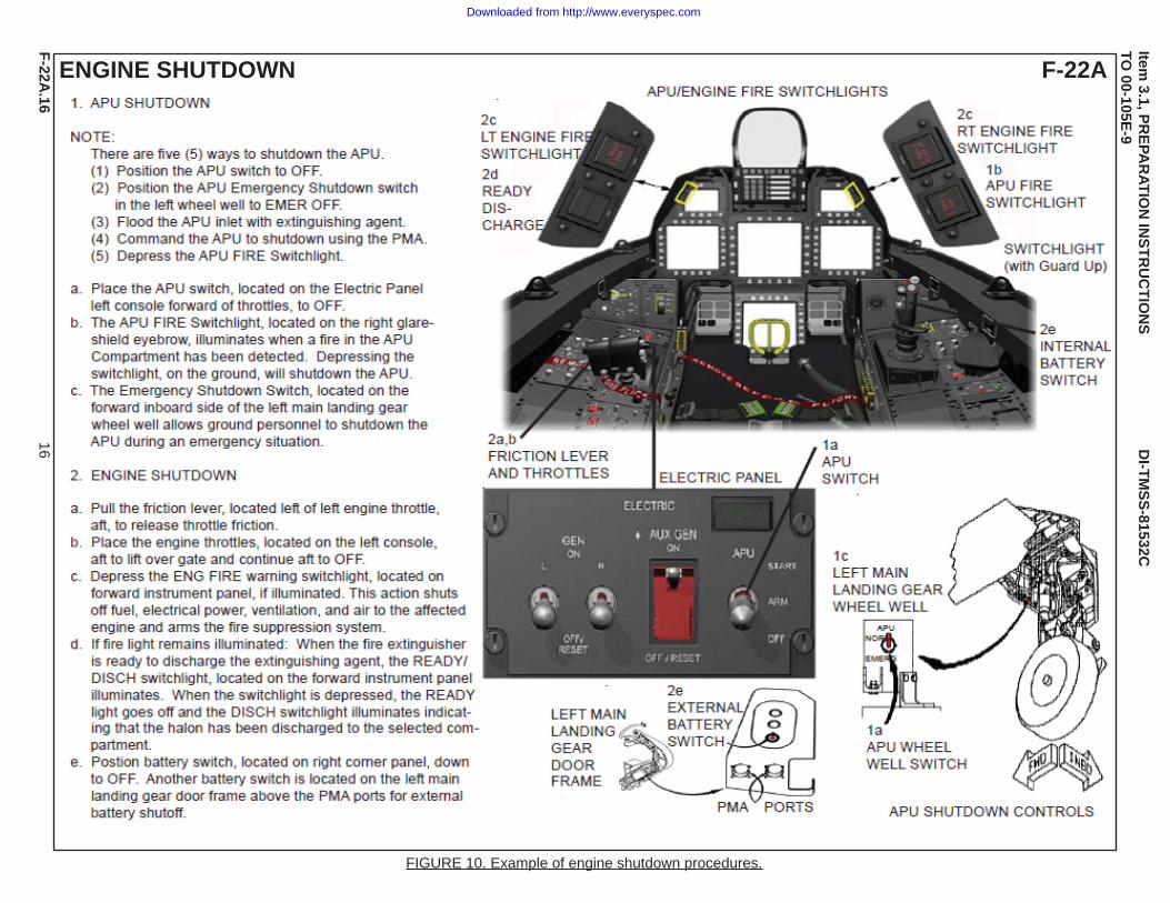
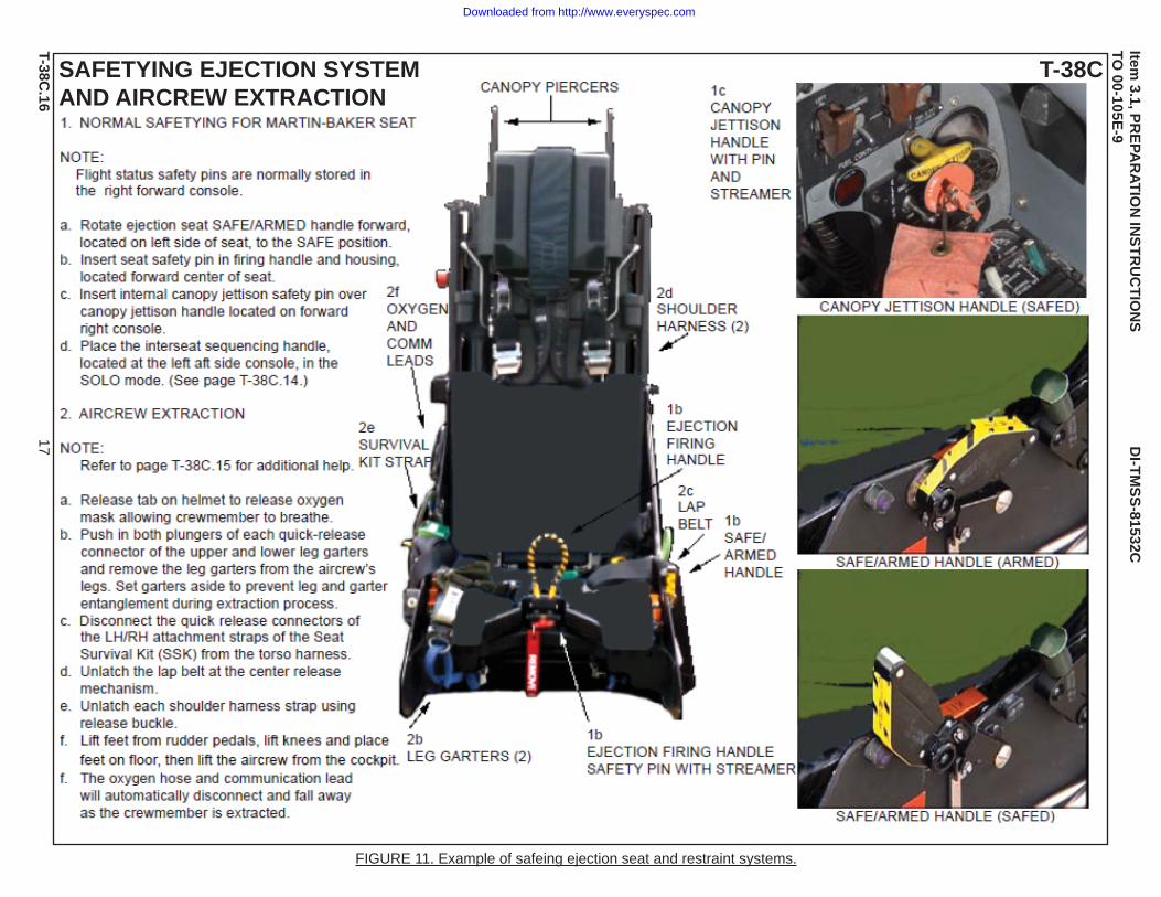
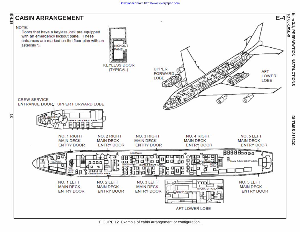
3.1.6 Composite material hazards. Illustrations and information for areas containing composite materials and types (organic, inorganic, or both) which would create additional hazards in a fire. This information includes burn potential flash points of the composite materials and any environmental risks (see Figure 5). 3.1.7 Aircraft dimensions. Illustrations and information for aircraft dimensions with landing gear in down position, (i.e., height, width, and length as a minimum). This information includes interior cubic footage to determine fire retardant agent usage and amount (see Figure 2). 3.1.8 Cockpit or flight deck. Illustrations and information for the cockpit or flight deck including controls for engine and APU shutdown (see Figure 10). 3.1.9 Cabin arrangement or configuration. Illustrations and information for cabin layout, crewmember and passenger configurations, capacity, and any possible locations outside the normal seating arrangements, i.e., galley, latrine, equipment, and maintenance areas or bays, etc., (see Figure 12). 3.1.10 Escape and ejection systems. Illustrations and information for escape and ejection systems employing pyrotechnics and their associated hazards. This information includes the safeing of such systems and required disconnection (e.g., oxygen and communication leads, etc.) enabling successful aircrew extraction and rescue (see Figure 11). General information about these systems is explained in Chapter 2.
4
Downloaded from http://www.everyspec.com
DI-TMSS-81532C
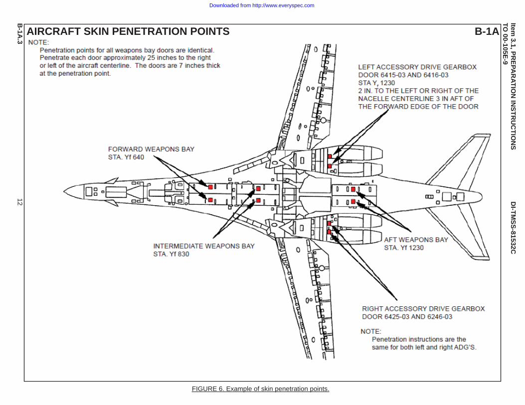
Item 3.1 PREPARATION INSTRUCTIONS (Continued) 3.1.11 Restraint devices. Illustrations and information for seats employing restraint devices and procedures for releasing occupants from the seats, including positioning levers, (i.e., inertial reel control, vertical, horizontal, tilt, and pedestal controls for shifting the seat forward or aft) (see Figure 11). General information about these systems is explained in Chapter 2. 3.1.12 Skin penetration points. Illustrations and information for skin penetration points and their dimensions for all potential fire areas. A broken line illustrates each area for skin penetration (see Figure 6). 3.1.13 Window cut-in areas. Illustrations and information for locations and dimensions of cut-in areas around all aircraft windows and their internal operation, if applicable (i.e., sliding open with associated controls, etc.). A broken line illustrates each area for cut-ins (see Figure 9). 3.1.14 Flotation equipment. Illustrations and information for the controls, locations, and use of flotation equipment deployment systems and any associated hazards during deployment. This information includes location and procedures for escape for overhead openings and hatch openings requiring ropes or ladders after deployment. 3.1.15 Fire extinguishers. Illustrations and information for fire extinguisher locations, capacities, and types of extinguishing agents. 3.1.16 Engine fire bottles. Illustrations and information for engine fire bottle (if any) locations, capacities, and types of extinguishing agents. 3.1.17 Oxygen systems. Illustrations and information for locations, capacities, and number of oxygen regulators, shutoff valves, and cylinders or bottles in the system (see Figures 7 and 8). 3.1.18 On Board Inert Gas Generating System (OBIGGS) and like systems as they are developed. Illustrations and information for any OBIGGS, as well as locations and capacities of nitrogen cylinders, and location of panel switches that control these systems (see Figures 7 and 8). 3.1.19 Hydraulics. Illustrations and information for locations and capacities of hydraulic fluid reservoirs and lines. This information is normally depicted on the aircraft entry page. 3.1.20 Hazardous materials. Illustrations and information for the material, health hazard, first aid treatment, fire hazard, location, and amount. (Details of these materials are either placed in specific aircraft files and/or fully explained in Chapter 3.)
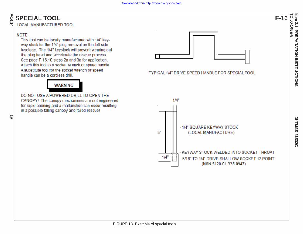
4. Special Tools and Equipment. Tools and equipment required for fire protection and emergency rescue specific to each aircraft. If any tools must be locally manufactured, this information includes complete instructions for fabrication of the tool such as parts required, procedures for fabrication and treating, special processes, etc., (see Figure 13). 5. Required Changes and Updates. Required changes and updates shall contain a separate package supporting the change. If more than one package of changes is submitted, the contractor shall divide the packages enabling the publications personnel to readily identify them. The packages shall be titled “Changes Required in Technical Manual 00-105E-9, Revision Number , Book Dated _____, Changes Dated _____.”
5
Downloaded from http://www.everyspec.com
DI-TMSS-81532C
5.1 Each page of each package shall be identified with the applicable technical manual number. An introductory statement in each package shall identify any modifications for this technical manual that are incorporated. 5.2. The source data shall contain essential information that will enable publications personnel to accomplish all required technical manual changes. When an illustration which is used in more than one technical manual has been changed, the publications personnel shall be informed of this illustration change which shall be incorporated in the source data for this technical manual. 6. Text Changes. Each recommended technical manual text change shall be identified and as closely associated by the relevant page, paragraph and sub paragraph number listed in the technical manual. New paragraphs and sub paragraphs to be added shall be identified and contain the essential information that will enable publications personnel to accomplish the change. 7. Illustration Changes. Illustration changes shall be identified by the relevant page, paragraph and sub paragraph of the technical manual. New illustrations to be added shall be identified and as closely associated by the relevant page, paragraph and sub paragraph of the technical manual. When illustration changes consist of only nomenclature or call- out changes, these changes may be identified by a textual description of the change(s) to be made. 8. End of DI-TMSS-81532C.
6
Downloaded from http://www.everyspec.com
Item 3.1, P
RE
PA
RA
TIO
N IN
ST
RU
CT
ION
S D
I-TM
SS
-81532CT
O 00-105E
-9
FIGURE 1. Example of aircraft paint scheme.
7
AIRCRAFT PAINT SCHEME F-22A
F-22A
.1
Downloaded from http://www.everyspec.com
Item 3.1, P
RE
PA
RA
TIO
N IN
ST
RU
CT
ION
S D
I-TM
SS
-81532CT
O 00-105E
-9
FIGURE 2. Example of aircraft dimensions.
8
AIRCRAFT DIMENSIONS F-117A
F-117A
.2
Downloaded from http://www.everyspec.com
Item 3.1, P
RE
PA
RA
TIO
N IN
ST
RU
CT
ION
S D
I-TM
SS
-81532CT
O 00-105E
-9
9
IMPACT DANGER AREAS C-17A
FIGURE 3. Example of external hazards.
C-17A
.3
Downloaded from http://www.everyspec.com
Item 3.1, P
RE
PA
RA
TIO
N IN
ST
RU
CT
ION
S D
I-TM
SS
-81532CT
O 00-105E
-9
FIGURE 4. Example of external hazards.
10
IMPACT DANGER AREAS B-2A
B-2A
.4
Downloaded from http://www.everyspec.com
Item 3.1, P
RE
PA
RA
TIO
N IN
ST
RU
CT
ION
S D
I-TM
SS
-81532CT
O 00-105E
-9
FIGURE 5. Example of airframe materials.
11
AIRFRAME MATERIALS F-117A
F-117A
.7
Downloaded from http://www.everyspec.com
Item 3.1, P
RE
PA
RA
TIO
N IN
ST
RU
CT
ION
S D
I-TM
SS
-81532CT
O 00-105E
-9
FIGURE 6. Example of skin penetration points.
12
AIRCRAFT SKIN PENETRATION POINTS B-1A
B-1A
.3
Downloaded from http://www.everyspec.com
Item 3.1, P
RE
PA
RA
TIO
N IN
ST
RU
CT
ION
S D
I-TM
SS
-81532CT
O 00-105E
-9
FIGURE 7. Example of list of special tools, number of personnel, entries, hatches, OBIGGS, and aircraft fuel quantities.
13
C-17A
C-17A
.18
SPECIAL TOOLS/EQUIPMENT35 FT Extension Ladder, “A” Frame LadderFlathead Screwdriver for Oxygen AccessPower Rescue Saw Portable Lights Fire Drill II
Downloaded from http://www.everyspec.com
Item 3.1, P
RE
PA
RA
TIO
N IN
ST
RU
CT
ION
S D
I-TM
SS
-81532CT
O 00-105E
-9
FIGURE 8. Example of general view depicting fuel, oxygen, armament, batteries, list of special tools, normal and emergency entry, cut-in procedures and miscellaneous information.
14
B-52
B-52.7
SPECIAL TOOLS/EQUIPMENTCowling Key Disarming Tool Rescue Harness (Local Mfg)25 Foot Ladder Fire Drill II
Downloaded from http://www.everyspec.com
Item 3.1, P
RE
PA
RA
TIO
N IN
ST
RU
CT
ION
S D
I-TM
SS
-81532CT
O 00-105E
-9
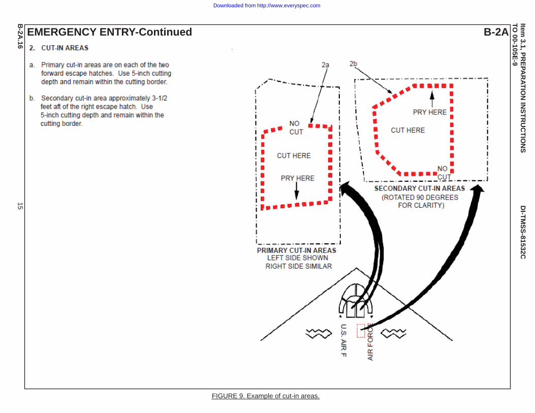
FIGURE 9. Example of cut-in areas.
15
EMERGENCY ENTRY-Continued B-2A
B-2A
.16
Downloaded from http://www.everyspec.com
Item 3.1, P
RE
PA
RA
TIO
N IN
ST
RU
CT
ION
S D
I-TM
SS
-81532CT
O 00-105E
-9
FIGURE 10. Example of engine shutdown procedures.
16
ENGINE SHUTDOWN F-22A
F-22A
.16
Downloaded from http://www.everyspec.com
Item 3.1, P
RE
PA
RA
TIO
N IN
ST
RU
CT
ION
S D
I-TM
SS
-81532CT
O 00-105E
-9
FIGURE 11. Example of safeing ejection seat and restraint systems.
17
SAFETYING EJECTION SYSTEMAND AIRCREW EXTRACTION
T-38C
T-38C.16
Downloaded from http://www.everyspec.com
Item 3.1, P
RE
PA
RA
TIO
N IN
ST
RU
CT
ION
S D
I-TM
SS
-81532CT
O 00-105E
-9
FIGURE 12. Example of cabin arrangement or confi guration.
18
CABIN ARRANGEMENT E-4
E-4.15
Downloaded from http://www.everyspec.com
Item 3.1, P
RE
PA
RA
TIO
N IN
ST
RU
CT
ION
S D
I-TM
SS
-81532CT
O 00-105E
-9
FIGURE 13. Example of special tools.
19
SPECIAL TOOL F-16
F-16.14
Downloaded from http://www.everyspec.com