Embed Size (px)
Citation preview

Data Sheet
Network Master™ SeriesMT1000ANetwork Master Pro
MU100010A10G Multirate Module

2 Data Sheet l MT1000A
Redefining Transport TestingToday’s communication networks are becoming more and more sophisticated as leading network operators install new technologies like OTN, MPLS-TP and Ethernet in their metro and backhaul networks and CPRI/OBSAI in Mobile Fronthaul networks. In some cases, operators must also support Fibre Channel links, while still keeping legacy technologies like SDH/SONET and PDH/DSn operational. The Network Master Pro MT1000A redefines the direction of future test platforms by bringing these network test requirements to a portable device, making it the ideal tool for field testing.The compact, battery-powered and easy-to-use Anritsu MT1000A with 10G Multirate Module MU100010A has everything in a single, handy tester needed to install and maintain communication networks from 1.5 Mbps to 10 Gbps. This portable, compact, lightweight instrument makes network field testing easy. Service engineers can read and interpret data from the tested network directly on the 9-inch color display with easy-to-understand indications and graphical symbols. And the GUI makes it simple to configure and operate the instrument at its full potential. The MT1000A has been designed for easy expandability, reducing initial costs, and facilitating step-by-step customized investment.
Key Benefits and Features:• All-in-one transport tester – supports testing from 1.5 Mbps to 10 Gbps
• Easy and intuitive GUI• Dual port at all rates• WLAN*/Bluetooth*/LAN connectivity• PDF, CSV and XML report generation for documenting test results
• Remote operation (VNC, dedicated remote GUI operation software)
• Remote control (scripting)• Compact, lightweight design for maximum field portability• Modular platform ensuring maximum return on investment
Key Applications:• Metro and core network installation and maintenance
• OTN up to OTU2 including mapping of Ethernet, CPRI, Fibre Channel, SDH/SONET client signals, multistage mapping and FEC (Forward Error Correction)
• Testing and verification of new OTN functions: ODU0 and ODUflex• Carrier Class Ethernet installation and troubleshooting
• Ethernet testing up to 10 Gbps including RFC 2544, RFC 6349 and Y.1564 • Ethernet OAM up to 10 Gbps• MPLS-TP and PBB/PBB-TE up to 10 Gbps• IP Channel Statistics up to 10 Gbps• Frame capture for advanced troubleshooting
• Mobile backhaul installation and verification• Synchronous Ethernet Testing up to 10 Gbps (ITU-T G.826x and IEEE 1588 v2)
• Mobile Fronthaul Installation and Verification• CPRI testing up to 10 Gbps• OBSAI testing up to 6 Gbps
• Powerful Storage Area Networking (SAN) testing• Fibre Channel up to 10 Gbps
• Quick and easy testing of SDH/SONET and PDH/DSn networks• SDH/SONET (STM-1 to 64/OC-3 to 192)• PDH/DSn (E1, E3, E4, DS1, DS3)
*: Available for certified countries and regions including USA, Canada, Japan and all EU countries. Please contact Anritsu for updated information.
The Bluetooth® mark and logos are registered trademarks of Bluetooth SIG, Inc.
1 Port 1, Tx Bantam (DS1)2 Port 1, Tx BNC
(E1, E3, E4, DS3, STM-1e, STS-3)3 Port 1, Rx Bantam (DS1)4 Port 1, Rx BNC
(E1, E3, E4, DS3, STM-1e, STS-3)5 Port 2, Tx Bantam (DS1)6 Port 2, Tx BNC
(E1, E3, E4, DS3, STM-1e, STS-3)7 Port 2, Rx Bantam (DS1)8 Port 2, Rx BNC
(E1, E3, E4, DS3, STM-1e, STS-3)9 Port 1, Tx/Rx RJ48 (E1 balanced)10 Port 2, Tx/Rx RJ48 (E1 balanced)11 Port 1, Tx/Rx SFP+ (OTN, Ethernet, CPRI/OBSAI,
Fibre Channel, SDH/SONET optical)12 Port 2, Tx/Rx SFP+ (OTN, Ethernet, CPRI/OBSAI,
Fibre Channel, SDH/SONET optical)13 Port 1, Tx/Rx RJ45 (Ethernet electrical)14 Port 2, Tx/Rx RJ45 (Ethernet electrical)15 Audio16 AUX17 Clock Input18 USB Mini-B19 USB A20 USB A21 Ethernet Service Interface22 DC Input (18 Vdc)23 9-inch Active TFT Display and Touch Screen24 Power Switch25 Speaker
1 2 3 4 5 6 7 8 9 10 11 12 13 14
15 16 17 18 19 20 21 22
23
25
24
Connector Panel Overview

Data Sheet l MT1000A 3
Specifications for Network Master Pro MT1000A Mainframe
User InterfacesDisplay 9-inch active TFT display (800 × 480 pixels) and touch screenSupported Languages English, Chinese, Japanese, French, Russian, Spanish
Service Interfaces
USB Data Interface MT1000A operates as host: USB 2.0 type A (2 ports)MT1000A operates as device: USB 2.0 type Mini-B (1 port)
Ethernet Interface Ethernet 10M/100M/1000M, Connector: RJ45WLAN Interface* IEEE 802.11 b/g/nBluetooth Interface* Bluetooth 2.1 +EDR
*: Available for certified countries and regions including USA, Canada, Japan and all EU countries. Please contact Anritsu for updated information.
Other Interfaces
Audio Interface For connection of optional head setConnector: 3.5-mm diameter jack
AUX Connector For connection of optional G0325A GPS receiver
Built-in Loudspeaker Monitors speech of voice channelOutput level: user-controlled from user Interface
Ext. Clock InputFor connection of external clock signals:
SETS (E1: 2.048 Mbps), BITS (DS1: 1.544 Mbps) or 2.048 MHz TTL signal in accordance with ITU-T G.703, 10 MHzConnector: BNC
Miscellaneous
Battery
10.8 V rechargeable and replaceable intelligent Li-ion batteryOperating time: 4 hours (typ.)Charging time: 3 to 6 hours (typ.)Remaining capacity indication: %
Mains Adapter Input: 100 V(ac) to 240 V(ac), 50 Hz/60 HzOutput: 18 V(dc), 3.62 A (Max.)
Dimensions and Mass 257 (W) × 164 (H) × 77 (D) mm ≤2.7 kg (including MT1000A, MU100010A and battery)
Environmental
TemperatureOperating : 0° to +50°C (non-condensing)Charging: 0° to +40°C (non-condensing)Storage: –30° to +60°C (non-condensing, without battery or AC adapter)
–20° to +50°C (non-condensing, with battery and AC adapter)Humidity
Operating: ≤85% RH (non-condensing)Storage and Transportation: ≤90% RH (non-condensing)
EMC EN61326-1, EN61000-3-2LVD EN61010-1Laser Safety*2 IEC 60825-1: 2007 CLASS 1, 21CFR1040.10 and 1040.11*1: MU100010A with optical modules
*1: Excludes deviations caused by conformance to Laser Notice No. 50 dated June 24, 2007*2: Safety measures for laser products
This product complies with optical safety standards in 21CFR1040.10, 1040.11 and IEC 60825-1; the following descriptive labels are affixed to the product.

4 Data Sheet l MT1000A
Specifications for 10G Multirate Module MU100010A
OTN Testing (Options MU100010A-001, MU100010A-051, MU100010A-052, MU100010A-061, MU100010A-062)
OTN TestTest Port • OTU2, OTU1e, OTU2e, OTU1f, OTU2f optical line interfaces: 1 port (MU100010A-051), 2 ports (MU100010A-052)
User-selectable optical modules: 1310 nm, 1550 nm• OTU1 optical line interfaces: 2 ports (MU100010A-001)
User-selectable optical modules: 1310 nm, 1550 nm Framing OTU2, OTU1e, OTU2e, OTU1f, OTU2f, OTU1Transmitter Clock • Internal clock accuracy: 4.6 ppm, Clock offset: ±50 ppm (1-ppm steps)
• Received clock• TTL level external 2 MHz clock• SETS (E1: 2.048 Mbps), BITS (DS1: 1.544 Mbps)• Signal from optional GPS receiver
Receive Signal Rate ±50 ppmFrequency deviation indication resolution: ±1 ppm
Scrambling Complies with ITU-T G.709OTN Mappings
OTU2 ODU/OPU2
ODU/OPUFlex
ODU/OPU1
ODTU01(PT=20)
OTU1
PRBS
FC-400
FC-800
CPRI Opt. 7/6
CPRI Opt. 5/4
CPRI Opt. 3
GFP-T
PRBS
STM-64/OC-192
PRBS
STM-16/OC-48
ODTU12(PT=20)
ODTU12(PT=21)
ODTU2.1
FC-200
PRBS
GigE
STM-4/STM-1/OC-12/OC-3
FC-100
ODU/OPU0
BMP
GMP BMP
BMP
GMPGMP
GMP
BMP
AMP
GMP
AMP
AMP
AMP
AMP
OTU2e/1e ODU/OPU2e/1e 10 GigE
PRBS
BMP
ODU/OPU2f/1f FC-1200
PRBS
BMPOTU2f/1f
MU100010A-051/052 OTN 10G Single/Dual ChannelMU100010A-011/012 Ethernet 10G Single/Dual ChannelMU100010A-081/082 STM-64 OC-192 Single/Dual ChannelMU100010A-091/092 FC 8G 10G Single/Dual ChannelMU100010A-001 Up to 2.7G Dual Channel
MU100010A-002 FC 1G 2G 4G Dual ChannelMU100010A-061 ODU MultiplexingMU100010A-062 ODU FlexMU100010A-071 CPRI/OBSAI Up to 5G Dual channelMU100010A-072/073 CPRI/OBSAI 6G to 10G Single/Dual channel
ODTU2.ts
GFP-F Ethernet
CPRI Opt. 2/1

Data Sheet l MT1000A 5
OTN Alarms Detected alarms• OTU layer: OTU-AIS, LOF, OOF, LOM, OOM, SM-TIM, SM-BIAE, SM-BDI, SM-IAE• ODU layer: LOS, ODU-AIS, ODU-OCI, ODU-LCK, PM-TIM, PM-BDI, FSF, FSD, BSF, BSD• ODU multiplexing: ODU-LOFLOM, ODU-OOF, OOM, ODU-AIS, ODU-OCI, ODU-LCK, PM-TIM, PM-BDI, MSIM• OPU layer: PLM, OPU-MSIM, Client-AIS, CSF, LSS• TCM: TCMi-TIM, TCMi-BIAE, TCMi-BDI, TCMi-IAE, TCMi-LTC (i = 1 to 6)Generated alarms• OTU layer: OTU-AIS, OTU-OOF/LOF, OOM/LOM, SM-TIM, SM-BIAE, SM-BDI, SM-IAE • ODU layer: ODU-AIS, ODU-OCI, ODU-LCK, PM-TIM, PM-BDI, FSF, FSD, BSF, BSD• ODU multiplexing: OOF/LOF, OOM/LOM, ODU-AIS, ODU-LCK, PM-TIM, PM-BDI, FSF, FSD, BSF, BSD• OPU layer: Client-AIS, CSF• TCM: TCMi-TIM, TCMi-BIAE, TCMi-IAE, TCMi-BDI, TCMi-LTC (i = 1 to 6)
OTN Errors Detected errors• OTU layer: FAS, MFAS, SM-BEI, SM-BIP8, FEC-Correctable, FEC-Uncorrectable• ODU layer: PM-BIP8, PM-BEI• OPU layer: Pattern error• GMP error: CRC8 error, CRC5 error• GFP errors: cHEC corrected, cHEC uncorrectable, tHEC corrected, tHEC uncorrectable, CSF Signal, SCF Sync,
Invalid GFP Frame, Superblock CRC, eHEC corrected, eHEC uncorrectable, FCS, CMF Sync, CMF Signal, SSF, PTI Mismatch, UPI Mismatch
• TCM: TCMi-BEI, TCMi-BIP-8 (i = 1 to 6)Generated errors• OTU layer: Bit all, FAS, OTU-FAS, MFAS, SM-BIP8, SM-BEI• ODU layer: PM-BIP8, PM-BEI, ODU-FAS• TCMi-BIP8, TCMi-BEI (i = 1 to 6)• Pattern error• GMP: CRC8, CRC5, Invalid JC1, Invalid JC2, Invalid JC1&JC2• GFP: cHEC, tHEC, Superblock CRC, eHEC, FCS, CMF
Inserted Error bits are editable.Error Performance • G.8201/M.2401 analysis of received signal based on detected errors and alarms: BBE, BBER, SES, SESR, UNAVJustification Analysis Count
AMP: Positive (+1), Positive (+2), Negative (–1), Offset (ppm)GMP: CRC8 Error, CRC5 Error, Inc, Inc > 1, Inc > 2, Inc Over, Dec, Dec > 1, Dec > 2, Dec Over, Offset (ppm), Cm (t) Max.,
Cm (t) Min. BER Test Pattern Pattern generation and detection for bulk test patterns:
• Test patterns: PRBS 9, PRBS 11, PRBS 15, PRBS 20, PRBS 23, PRBS 29, PRBS 31 PRBS patterns can be inverted.
• User-defined patterns (Pattern length: 2048 bits, 32 bits)FEC Test ITU-T O.182 Random error insertionOverhead User-editable header bytes
• OTU layer: FAS, SM, GCC0, RES• ODU layer: PM, FTFL, APS/PCC, GCC1, GCC2, RES, EXP, TCMi (i = 1 to 6)• OPU layer(s): PSICapture and display current overhead bytes
The following signals are decoded: TTI (SM, PM, TCMi (i = 1 to 6) of high-order, FTFL, PT)Tributary Signal Ethernet functionality is supported for Ethernet signals embedded in selected ODU-n
(Requires MU100010A-061, MU100010A-062 and MU100010A-001/011/012)SDH/SONET functionality is supported for SDH/SONET signals embedded in selected ODU-n (Requires MU100010A-061 and MU100010A-001/081/082)Fibre Channel functionality is supported for Fibre Channel signals embedded in selected ODU-n (Requires MU100010A-061 and MU100010A-002/091/092)
Through Mode • Transparent mode• OH overwrite modeThe OTU, ODU and OPU overhead can be changed.The FEC encoder and decoder can be set On/Off in any mode
OTN ResultsStatus Current information on:
• Alarms and errors on monitored line• Input level indication for optical signals• Frequency• Frequency deviation
Statistics User-defined measurement resolution: 1, 2, 5, 10, 15, 30 s, 1, 5, 10, 15, 30 min, 1, 2, 4, 6, 12 hLogged information: Alarms (s), Errors (count or count and ratio), Client Frequency, DeviationEvent log: Major measurement events incl. errors and alarms are logged with 1-second resolution.
APS APS (Automatic Protection Switching) test and analysis• APS switching time is measured. A switching time exceeding the user-defined threshold is highlighted.• Start and stop triggers can be selected independently.
• Trigger events can be selected from the high-order OTU and ODU, Pattern bit error, LOS (Loss of Signal).• Switching time, Switching count, Pass/Fail, Minimum, Maximum and Average can be displayed.APS switching time measurement resolution: 0.1 ms
Round Trip Delay (Propagation Time) Measurement
Resolution: 0.1 µsMeasured Max. time: 10.0 sInterval: 0.5, 1, 2, 5, 10 s

6 Data Sheet l MT1000A
Ethernet Testing (Options MU100010A-001, MU100010A-011, MU100010A-012)
Ethernet TestTest Port • Optical line interfaces 10 Gbps (10G LAN-PHY and 10G WAN-PHY): 1 port (MU100010A-011) or 2 ports (MU100010A-012)
User-selectable optical modules: 850 nm (SR), 1310 nm (LR), 1550 nm (ER) NB: Correct functioning can be guaranteed only with optical modules purchased from Anritsu for the MU100010A.
• Optical line interfaces: 2 ports (MU100010A-001) 1000 Mbps User-selectable optical modules: 850 nm (SX), 1310 nm (LX) and 1550 nm (ZX) or 100 Mbps 1310 nm (FX) NB: Correct functioning can be guaranteed only with optical modules purchased from Anritsu for the MU100010A.
• Electrical line interfaces: 2 ports (MU100010A-001) (in addition to optical ports) RJ45: 10 Mbps, 100 Mbps, 1000 Mbps (unshielded and shielded twisted pair cables, category 5, 5E, 6)
Test Configuration • Monitor/Generate, Pass-through, ReflectorEncapsulation • EtherType II (DIX v.2), IEEE 802.3 with 802.2 (LLC1), IEEE 802.3 with SNAP
Configuration, Monitor/GenerateTraffic Generation • Variable line rate traffic generation, up to full line rate
• Line load profile: Constant, Ramp• Traffic duration: Continuous, Programmable number of seconds or frames• Adjustable frame size: 44 bytes to 16000 bytes• Frame sizes: Constant, Stepped, Random• Payload profiles: Data, Video, Voice• User-defined traffic mix of unicast and broadcast frames• Fixed or incremented IP identifier• User programmable DSCP/TOS byte• Configurable IP and Ethernet source and destination addresses (supports IPv4 and IPv6 addressing)
IPv4: Fixed, DHCP, DNS IPv6: Fixed• Address increment, Decrement and Random generation supported
• User programmable UDP/TCP address• Automatic TCP connect (user selectable)• UDP check sum: Automatic, Fixed (null); TCP check sum: Automatic • Generate pause frames, Respond to pause frames• Answer incoming ARP, Ping requests (On/Off)
Stacked VLAN Up to 8 user-settable VLAN tagsParameters per VLAN tag:• Ether-type 0x8100 (802.1Q), 0x88a8 (802.1ad), 0x9100 or 0x9200 • User-defined VLAN ID, CFI, VLAN priority
• Address increment, Decrement and Random generation supportedOnly one VLAN level supported at ping, traceroute and RFC 2544 router latency tests
Multistream Number of streams: Up to 16 streams per port can be activatedTiming Functionality Timing sources (selectable): Internal, Received clock, 2-MHz signal, SETS (E1: 2.048 Mbps), BITS (DS1: 1.544 Mbps),
PTP (IEEE 1588 v2) recovered clock or signal from optional GPS receiverFrequency deviation: ±100 ppm (1-ppm steps)The frequency deviation of received Ethernet signals can be measured against the internal clock.
Receiver Setting • User-defined expected preamble length: 3 bytes to 15 bytes• User-defined IFG lower threshold: 8 bytes to 15 bytes (Ethernet 10 Mbps, 100 Mbps, 1000 Mbps)• User-defined Jumbo frame size upper limit: 1519 bytes to 16000 bytes
Error Generation FCS, Preamble, Error symbol, IFG for ethernet 10 Mbps, 100 Mbps, 1000 Mbps, Wrong IP check sum, Fragmented IP, Wrong layer 4 check sum, PRBS bit error, BER test sequence error
Alarm Generation No link, Remote fault, Local fault (Ethernet 10 Gbps)
Result, Monitor/Generate Status • Link status, Interface type, Jabber detected, Frames present, MPLS/EoMPLS/VLAN, Speed, Full or half duplex,
Local clock (Ethernet 1000 Mbps), LFS LF/RF (Ethernet 10 Gbps), Signal present, Bit rate of incoming Ethernet signal, Auto negotiation complete
• Link partner abilities: Pause capable and Asymmetric pause request (not Ethernet 10 Gbps), Remote fault, Speed/Duplex• Indicators for Utilization, Throughput and Errored frames• Signal level indication for optical Ethernet interfaces
Resolution User-defined resolution for statistical measurements: 1, 2, 5, 10, 15, 30 s, 1, 5, 10, 15, 30 min, 1, 2, 4, 6, 12 hEvent log: Major measurement events incl. errors and alarms are logged with 1-second resolution.
Performance Statistics • Utilization (Max./Min./Avg.), Throughput (Max./Min./Avg.), Frame rate (Max./Min./Avg.)Frame Statistics • Total frames, Total valid frames, Unicast/Multicast/Broadcast frames, Number of pause frames
• Number of VLAN tagged frames, Max. number of VLAN layers detected, Last received VLAN ID, Last received VLAN priority• Number of MPLS frames and MPLS-TP frames. Max. number of MPLS layers detected. Last received MPLS Label,
MPLS Priority and MPLS TTL.• Number of PBB frames. Last received B/I-tag ID and B/I-tag priority.• Total errored frames, Fragmented frames, Number of oversized and undersized (runts) frames, Number of FCS errored
frames, Error symbol frames (not Ethernet 10 Gbps)/Code violation frames (Ethernet 10 Gbps), Number of collisions (10 Mbps, 100 Mbps half duplex), Preamble violations, IFG violations (Ethernet 10 Mbps, 100 Mbps, 1000 Mbps), False carrier, 10G LFS LF (local fault), 10G LFS RF (remote fault)
Burst Statistics Total frames, Total valid frames, Number of burst, Total frames in bursts, Burst size (Max./Min./Avg.)Frame Distribution Statistics • Total valid/ frames, 64 to 127, 128 to 255, 256 to 511, 512 to 1023, 1024 to 1518 byte frames, Total number of jumbo frames
• Frame size (Max./Min./Avg.)Multistream Statistics Available information per stream:
• Frame loss count/rate, Throughput, Latency, Packet jitter, Frames and bytes received and transmitted

Data Sheet l MT1000A 7
Transmit Statistics Total frames, Total valid frames, Unicast/Multicast/Broadcast frames, FCS errors, Total errors64 to 127, 128 to 255, 256 to 511, 512 to 1023, 1024 to 1518 byte frames, Total number of jumbo framesTotal number of frames (Tx (own port) – Rx (selectable port))
Filter Up to 8 filter conditions can be defined. Each condition can filter using:
IP or MAC source address, IP or MAC destination address, Broadcast address, IEEE OUI value, Encapsulation type, VLAN ID and VLAN tag priority, MPLS, PBB source and destination MAC address, PBB B/I-tag, MPLS-TP source and destination MAC address, TPC/UDP source and destination port, User-defined pattern at defined offset
Adjustable Threshold Utilization, Throughput, Errored frames, Collision rate, Unicast frames, Multicast frames, Broadcast frames, Pause frames, Fragmented frames, Undersized frames (runts), Oversized frames, FCS errored frames, IFG violations (Ethernet 10 Mbps, 100 Mbps, 1000 Mbps), Preamble violations, BER test pattern errors, Sequence errors, Diff.Tx-Rx
DHCP • Display source IP address assigned by DHCP• Display current lease expire time• Display IP addresses of primary and secondary DNS server when obtained by DHCP• Gateway setup using DHCP
BER Test and Service Disruption MeasurementBER Test Generation and detection of test patterns, Count of errors in received test pattern, Pattern generation: Unframed (Layer 1),
Framed Ethernet (MAC) header (Layer 2), Framed Ethernet (MAC) header with IP header (Layer 3) or Framed Ethernet (MAC) header, Framed with IP header and TCP/UDP header (Layer 4)Detection of sequence errors and loss of sequence synchronizationFrame loss count and frame loss secondsThroughput measurement results are calculated for:• Utilization layer, Physical layer, Physical layer excluding preamble, Link layer, Network layer and Data layer• Min./Max./Avg. valuesPerformance (M.2100 type) parameters: ES, SES, ALS, UAT, AVT, EFSTest patterns: PRBS 9, PRBS 11, PRBS 15, PRBS 20, PRBS 23, PRBS 29, PRBS 31, HF test pattern, CRPAT, JTPAT,
SPAT, 55 Hex, Fox, 32-bit user programmableUser-defined resolution: 1, 2, 5, 10, 15, 30 s, 1, 5, 10, 15, 30 min, 1, 2, 4, 6, 12 hEvent log: Major measurement events incl. errors and alarms are logged with 1-second resolution.
Error Generation FCS, Preamble, Error symbol, IFG for Ethernet (10 Mbps, 100 Mbps, 1000 Mbps), Wrong IP check sum, Fragmented IP, Wrong layer 4 check sum, PRBS bit error, BER test sequence error
Alarm Generation No link, Remote faultService Disruption Measurement Service disruption measurement activated as part of BER test
• Max./Avg. service disruption time, Resolution: 0.1 µs• Number of service disruptions• Disruption Type: Packet, LOS
RFC 2544 TestRFC 2544 Test Switch/Router test and Single ended network test modes:
• Throughput, Frame loss, Latency or Packet jitter, Back-to-back frames (burstability)End-to-end network test mode (two MU100010A units in Local-remote setup)• Throughput, Frame loss, Back-to-back frames (burstability)Router latency test mode: IP ping based latency test or packet jitter
Service Activation Test (Y.1564)Service Activation Test ITU-T Y.1564 Service Activation Test
• Up to 8 services per port• Color-aware and non-color-aware in combinations (IP DSCP or VLAN PCP)• Test modes: One-way (uni- or bi-directional, symmetrical or asymmetrical), Round-trip• Verification against service acceptance criteria: Information rate, Frame transfer delay, Frame delay variation,
Frame loss rate, AvailabilityOptional GPS timing synchronization
Service Configuration Test • Subtests for: Committed information rate, Excess information rate, Traffic policing, Committed burst size, Excess burst size• Step duration: 1 s to 60 s (user programmable)• Number of steps: 1 to 10 (user programmable)• Slope: Rising/Falling• Results: Pass/Fail indication, IR (Min./Avg./Max.), FL (Count/FLR), FTD, FDV (Min./Avg./Max./Current (during measurement))
Service Performance Test • All services tested simultaneously at CIR• Duration 15 min, 2 h, 24 h, user programmable• Results: Pass/Fail indication, IR (Min./Avg./Max.), FL (Count/FLR), FTD, FDV (Min./Avg./Max./Current (during measurement)),
AVAIL (%), Unavail (s)

8 Data Sheet l MT1000A
RFC 6349 TCP Throughput Test (MU100010A-020 TCP Throughput)TCP Throughput Test TCP Throughput Test According to RFC 6349
Supports connecting to iPerf serverTest Direction Setup• Local → Remote• Remote → Local• Simultaneous in both directionsFor RFC 6349 test sequence, user can choose to measure for:
• Path MTU• Baseline RTT• Window Scan and Throughput• Multi-Service
Multi-Service: DSCP or TOS can be set to each TCP connectionsMeasurement results include:
• Auto-calculation of Bandwidth Delay Product (BDP)• Transmitted and Retransmitted Bytes• TCP Transfer Time Ratio• TCP Efficiency• Retransmitted Percentage• Buffer Delay Percentage
Cable Test Cable Test Identifies cable faults like short circuits, or breaks in wire pair, and displays distance from instrument to fault
Ping Test and Traceroute Ping Test For Connectivity and Configuration check
• Round Trip Time (RTT)• Supports IPv4 and IPv6 addressing• Answer incoming ping requests (On/Off)
Traceroute Trace IP route over IP network• User-defined Max. number of hops (1 to 255)Information per hop: Ping time (Min./Max./Avg.), Number of ping timeouts
IP Channel Statistics Statistics Statistics for up to 230 channels, identified by user-defined combinations of:
• IPv4, IPv6 or MAC address• VLAN ID or MPLS label• Protocol information• IP next header (protocol)• TCP/UDP portsTraffic capacity:• 10 Mbps, 100 Mbps, 1 Gbps, 10 Gbps, line speeds: 100% line loadAvailable Information per channel:• Frame count/rate, Throughput, Byte count, MPLS frames, IP frame/packet size distribution, IP header bytes, IP fragments,
TTL threshold violations, IP packet count/rate, IP bytes, IP throughput, IP header errors, TCP/UDP bytes, TCP/UDP packet count/rate, Throughput, TCP/UDP errored packets, Undersize frames, Oversize frames
MPLS/MPLS –TP Number of MPLS Header Up to 8 MPLS headers set by userParameters per MPLS Header User-defined label, Exp and TTL fields in each MPLS header
• Address increment, Decrement and Random generation An EoMPLS (Ethernet over MPLS) or PWE3 (Pseudo-wire emulation edge-to-edge) label (RFC 4448 control word) can be added. MPLS can only transport VLAN if EoMPLS activated.
Statistics • Number of labels (Max./Min.)• Number of MPLS-TP frames• Last received MPLS-TP label/priority/TTL
OAM (MPLS-TP) ITU-T G.8113.1 complySupported OAM messages• ITU-T Y.1731: CCM, LBM, LBR, LTM, LTR, AIS, LCK, TST, MCC, LMM, LMR, 1DM, DMM, DMR, EXM, EXR, VSM, VSR,
SLM, SLR• IEEE 802.1ag: CCM, LBM, LBR, LTM, LTR
PBB/PBB-TE (Mac-in-Mac MiM)Programmable Field B-tag, I-tag, MAC destination and source addressesResult Number of PBB frames, Last received B-tag VLAN ID, Last received B-tag priority, Last received I-tag priority,
Last received I-tag service IDOAM Supported OAM messages
• ITU-T Y.1731: CCM, LBM, LBR, LTM, LTR, AIS, LCK, TST, MCC, LMM, LMR, 1DM, DMM, DMR, EXM, EXR, VSM, VSR, SLM, SLR
• IEEE 802.1ag: CCM, LBM, LBR, LTM, LTR
Data Sheet l MT1000A 9
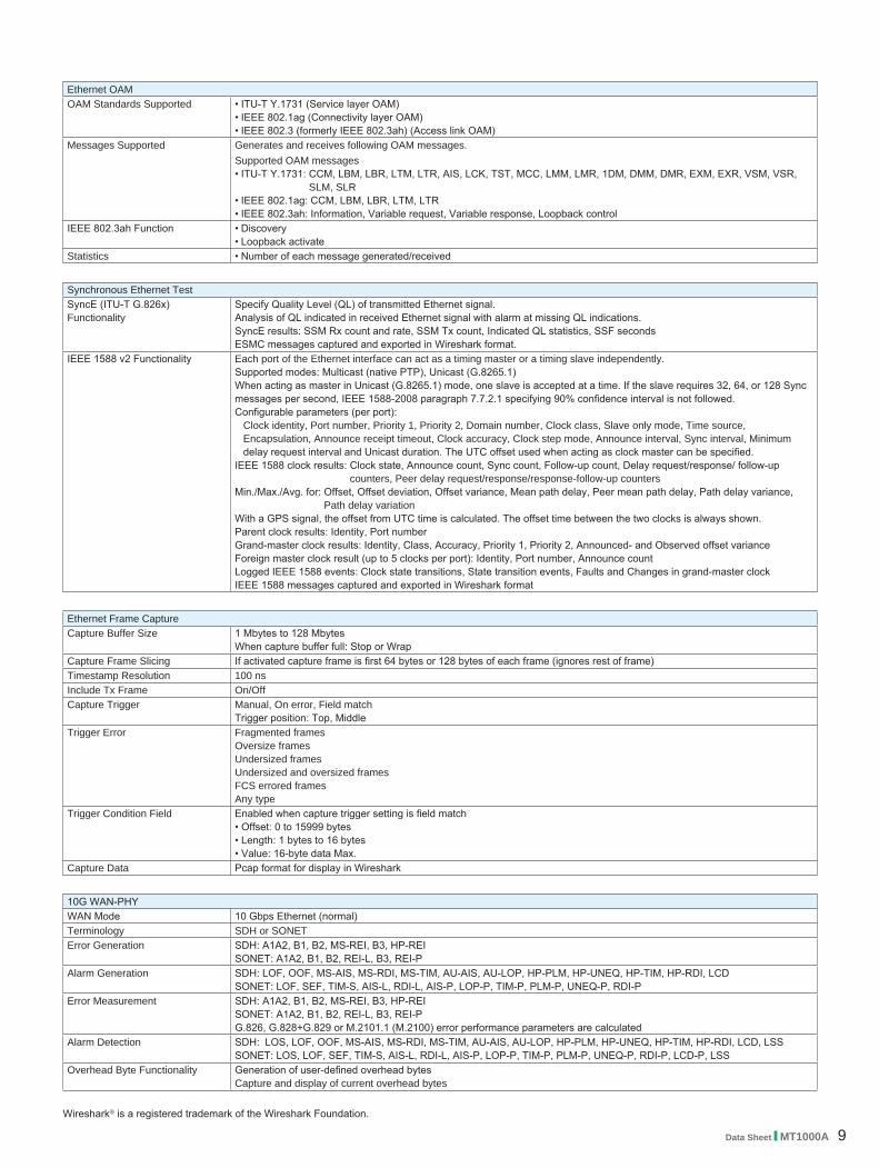
Ethernet OAMOAM Standards Supported • ITU-T Y.1731 (Service layer OAM)
• IEEE 802.1ag (Connectivity layer OAM)• IEEE 802.3 (formerly IEEE 802.3ah) (Access link OAM)
Messages Supported Generates and receives following OAM messages.Supported OAM messages• ITU-T Y.1731: CCM, LBM, LBR, LTM, LTR, AIS, LCK, TST, MCC, LMM, LMR, 1DM, DMM, DMR, EXM, EXR, VSM, VSR,
SLM, SLR• IEEE 802.1ag: CCM, LBM, LBR, LTM, LTR• IEEE 802.3ah: Information, Variable request, Variable response, Loopback control
IEEE 802.3ah Function • Discovery• Loopback activate
Statistics • Number of each message generated/received
Synchronous Ethernet Test SyncE (ITU-T G.826x) Functionality
Specify Quality Level (QL) of transmitted Ethernet signal.Analysis of QL indicated in received Ethernet signal with alarm at missing QL indications.SyncE results: SSM Rx count and rate, SSM Tx count, Indicated QL statistics, SSF secondsESMC messages captured and exported in Wireshark format.
IEEE 1588 v2 Functionality Each port of the Ethernet interface can act as a timing master or a timing slave independently.Supported modes: Multicast (native PTP), Unicast (G.8265.1)When acting as master in Unicast (G.8265.1) mode, one slave is accepted at a time. If the slave requires 32, 64, or 128 Sync messages per second, IEEE 1588-2008 paragraph 7.7.2.1 specifying 90% confidence interval is not followed.Configurable parameters (per port):
Clock identity, Port number, Priority 1, Priority 2, Domain number, Clock class, Slave only mode, Time source, Encapsulation, Announce receipt timeout, Clock accuracy, Clock step mode, Announce interval, Sync interval, Minimum delay request interval and Unicast duration. The UTC offset used when acting as clock master can be specified.
IEEE 1588 clock results: Clock state, Announce count, Sync count, Follow-up count, Delay request/response/ follow-up counters, Peer delay request/response/response-follow-up counters
Min./Max./Avg. for: Offset, Offset deviation, Offset variance, Mean path delay, Peer mean path delay, Path delay variance, Path delay variation
With a GPS signal, the offset from UTC time is calculated. The offset time between the two clocks is always shown.Parent clock results: Identity, Port numberGrand-master clock results: Identity, Class, Accuracy, Priority 1, Priority 2, Announced- and Observed offset varianceForeign master clock result (up to 5 clocks per port): Identity, Port number, Announce countLogged IEEE 1588 events: Clock state transitions, State transition events, Faults and Changes in grand-master clockIEEE 1588 messages captured and exported in Wireshark format
Ethernet Frame Capture Capture Buffer Size 1 Mbytes to 128 Mbytes
When capture buffer full: Stop or WrapCapture Frame Slicing If activated capture frame is first 64 bytes or 128 bytes of each frame (ignores rest of frame)Timestamp Resolution 100 nsInclude Tx Frame On/OffCapture Trigger Manual, On error, Field match
Trigger position: Top, MiddleTrigger Error Fragmented frames
Oversize framesUndersized framesUndersized and oversized framesFCS errored framesAny type
Trigger Condition Field Enabled when capture trigger setting is field match• Offset: 0 to 15999 bytes• Length: 1 bytes to 16 bytes• Value: 16-byte data Max.
Capture Data Pcap format for display in Wireshark
10G WAN-PHYWAN Mode 10 Gbps Ethernet (normal)Terminology SDH or SONETError Generation SDH: A1A2, B1, B2, MS-REI, B3, HP-REI
SONET: A1A2, B1, B2, REI-L, B3, REI-PAlarm Generation SDH: LOF, OOF, MS-AIS, MS-RDI, MS-TIM, AU-AIS, AU-LOP, HP-PLM, HP-UNEQ, HP-TIM, HP-RDI, LCD
SONET: LOF, SEF, TIM-S, AIS-L, RDI-L, AIS-P, LOP-P, TIM-P, PLM-P, UNEQ-P, RDI-PError Measurement SDH: A1A2, B1, B2, MS-REI, B3, HP-REI
SONET: A1A2, B1, B2, REI-L, B3, REI-PG.826, G.828+G.829 or M.2101.1 (M.2100) error performance parameters are calculated
Alarm Detection SDH: LOS, LOF, OOF, MS-AIS, MS-RDI, MS-TIM, AU-AIS, AU-LOP, HP-PLM, HP-UNEQ, HP-TIM, HP-RDI, LCD, LSSSONET: LOS, LOF, SEF, TIM-S, AIS-L, RDI-L, AIS-P, LOP-P, TIM-P, PLM-P, UNEQ-P, RDI-P, LCD-P, LSS
Overhead Byte Functionality Generation of user-defined overhead bytesCapture and display of current overhead bytes
Wireshark® is a registered trademark of the Wireshark Foundation.

10 Data Sheet l MT1000A
CPRI/OBSAI Testing (Options MU100010A-071, MU100010A-072, MU100010A-073)
CPRI/OBSAI TestingPort Mode Off, Normal, ThroughLine Rate CPRI: 614.4, 1228.8, 2457.6, 3072.0, 4915.2, 6144.0, 9830.4, 10137.6 Mbps
OBSAI: 768, 1536, 3072.0, 6144.0 MbpsTransmitter Clock Reference Clock
• Internal clock• External clock
• BITS• SETS• 2 MHz• 10 MHz
• GPS• Received clock
Content Unframed, CPRI LinkPattern PRBS 15, PRBS 20, PRBS 23, PRBS 29, PRBS 31, User 32 bits, OffCPRI Link Start up: Enabled, Disabled
Role: Master, SlaveProtocol version: 1, 2HDLC rate: no HDLC, 240, 480, 960, 1920, 2400 kbit/s, Highest possibleEthernet: On, Off; Pointer: 20 to 63
Alarm Insertion Signal Loss, LOS, LOF, PSL, Remote-LOS, Remote-LOF, RAI, SDI, ResetError Insertion Item: LCV, SHV, K30.7, Pattern error
Insertion timing: Manual, RateFrequency Offset ±100 ppm, 1-ppm stepsAlarm Detection Signal loss, LOS, LOF, PSLError Detection LCV, SHV, K30.7, Pattern errorRemote Status Remote LOS, Remote LOF, RAI, SDI, ResetLink Rx: Protocol version, HDLC rate, Pointer P
Tx: Protocol version, HDLC rate, Pointer PBER Test Alarms: Signal loss, LOS, LOF, PSL, Remote LOS, Remote LOF, RAI, SDI, Reset
Errors: LCV, SHV, K30.7, Pattern errorFrames count: Rx hyper frame, Rx code words, Tx hyper frame, Tx code wordsDelay: Delay, Average Delay, Min. Delay, Max. DelayMeasurement count
Pass Through Alarms: Signal loss, LOS, LOF, PSL, Remote LOS, Remote LOF, RAI, SDI, ResetErrors: LCV, SHV, K30.7, Pattern error
ReflectorReflector Mode The following parameters are user selectable:
• Reflector MAC/IP address• Swap all MAC addresses or one specific MAC address• Swap IP addresses• Swap port numbers on UDP/TCP frames• Force ACK on TCP frames• Answer incoming ARP, Ping requests

Data Sheet l MT1000A 11
Fibre Channel Testing (Options MU100010A-002, MU100010A-091, MU100010A-092)
Fibre Channel TestTest Port • FC-800 (8GFC), FC-1200 (10GFC) optical line interfaces: 1 port (MU100010A-091), 2 ports (MU100010A-092)
User-selectable optical modules: 1310 nm, 1550 nm• FC-100 (1GFC), FC-200 (2GFC), FC-400 (4GFC) optical line interfaces: 2 ports (MU100010A-002)
User-selectable optical modules: 1310 nm, 1550 nmSupported FC Bit Rate 1.0625 Gbps (FC-100/1GFC), 2.125 Gbps (FC-200/2GFC), 4.25 Gbps (FC-400/4GFC), 8.5 Gbps (FC-800/8GFC),
10.52 Gbps (FC-1200/10GFC)Mode Terminate, Monitor, ReflectorTopology Point-to-pointPrimitive Sequence Protocol Count and transmit primitive sequence: LR, LRR, NOS, OLSFlow Control Credit based transmitter: On/Off
Buffer-to-buffer credit configuration: 1 to 65535, Buffer-to-buffer credit and R_RDY counters, R_RDY injectionTraffic Generation • 1GFC (with SOF and EOF frame delimiters and 2GFC frames), Class-3 service frames
• Traffic shaping: Constant, Ramp, Burst, 2GFC frame header configuration • Frame length configuration: 3240 bytes (Max.)
BER Test • Test modes: Unframed BER test, Layer 1 BER test, Layer 2 BER test• Test patterns: PRBS 9, PRBS 11, PRBS 15, PRBS 20, PRBS 23, PRBS 29, PRBS 31, HF test pattern, CSPAT, CJPAT,
CRPAT, JTPAT, SPAT, 55 Hex, Fox, 32-bit user programmable• Error injection: Bit, CRC, Symbol• Results: Pattern loss seconds, Traffic loss seconds, Bit error count, BER
Measurement • Alarm detection: LOS, Link down, Pattern loss• Service disruption measurement: Average/Max service disruption, Number of service disruptions• Traffic statistics: Bandwidth utilization, Data rate, Frame count, Byte count, Frame size distribution,
Buffer-to-buffer credit count, R_RDY count, Frame loss count, Round trip delay, Packet jitter, Bit errors, CRC errors, Symbol errors, LR, LRR, NOS, OLS

12 Data Sheet l MT1000A
SDH/SONET and PDH/DSn Testing (Options MU100010A-001, MU100010A-081, MU100010A-082)
SDH and SONET TestTest Port • STM-64, OC-192 optical interfaces: 1 port (MU100010A-081), 2 ports (MU100010A-082)
User-selectable optical modules: 1310 nm, 1550 nm• STM-16/STM-4/STM-1, OC-48/OC-12/OC-3 optical interfaces: 2 ports (MU100010A-001)
User-selectable optical modules: 1310 nm, 1550 nm • STM-1e, STS-3 electrical interfaces: 2 ports (MU100010A-001)
Connector: BNCFraming SDH: Complies with ITU-T G.707, SONET: Complies with Telcordia GR-253Transmitter Clock • Internal clock accuracy: 4.6 ppm, Clock offset: ±50 ppm (1-ppm steps)
• Recovered clock• TTL level external 2 MHz clock• SETS (E1: 2.048 Mbps), BITS (DS1: 1.544 Mbps)
Receive Signal Rate ±50 ppmFrequency deviation indication resolution: ±1 ppm
STM-1e Electrical Attenuation and Impedance Mode
TERMINATE: Up to 12 dB cable attenuation, Nominal impedance MONITOR: 20 dB linear attenuation and up to 12 dB cable attenuation, Nominal impedance
TCM Frame Format ITU-T G.783, G.707 Annex D (TCM option 2) and Annex E, POH bytes: N1 (VC-4, VC-3), Z5 (STS-3c, STS-1), N2 (VC-12, VC-11), Z6 (VT-2, VT-1.5)
TCM Access Point Identifier (Apid): 15 bytes ASCII sequence, CRC-7Scrambling SDH: Complies with ITU-T G.707, SONET: Complies with Telcordia GR-253SDH Mappings
STM-64 AUG-64 VC4-64cAU-4-64c C-4-64c
STM-16 AUG-16 VC4-16cAU-4-16c C-4-16c
Bulk
Bulk
Bulk
E4, Bulk
E1, Bulk
DS1, Bulk
E3, Bulk
STM-4 AUG-4 VC4-4cAU-4-4c C-4-4c
STM-1/STM-1e AUG-1 VC4
TUG-3 C-3VC-3
C-12VC-12
C-11VC-11
TUG-2
AU-4
AU-3
C-4
DS3, BulkC-3VC-3
1) Requires MU100010A-081 or MU100010A-0822) Requires MU100010A-001
1)
2)
2)
2)
SONET Mappings
OC-192 STS-192 STS-192c STS-192c SPE
OC-48 STS-48 STS-48c STS-48c SPE
OC-12 STS-12 STS-12c STS-12c SPE
OC-3/STS-3 STS-3 STS-3c STS-3c SPE
STS-1 STS-1 SPE
VT Group VT-2 VT-2 SPE
VT-1.5 VT-1.5 SPE
Bulk
Bulk
Bulk
E4, Bulk
DS3, Bulk
E1, Bulk
DS1, Bulk1) Requires MU100010A-081 or MU100010A-0822) Requires MU100010A-001
1)
2)
2)
2)
TUG-3E3, Bulk
C-3VC-3

Data Sheet l MT1000A 13
Alarms Detected and generated alarms • SDH: LOS, LOF, OOF, MS-AIS, MS-RDI, AU-AIS, AU-LOP, HP-PLM, HP-UNEQ, HP-TIM, HP-RDI, TU-LOM, TU-AIS,
TU-LOP, LP-PLM, LP-UNEQ, LP-TIM, LP-RDI, LSS• SONET: LOS, LOF, OOF, AIS-L, RDI-L, AIS-P, LOP-P, TIM-P, PLM-P, UNEQ-P, RDI-P, LOM-V, AIS-V, LOP-V, PLM-V,
UNEQ-V, RDI-V, TIM-V, LSS• TCM: TC-LTC, TC-TIM, TC-UNEQ, TC-AIS, TC-RDI, TC-ODIInserted alarms• Permanent• Alternate: 1 to 8000 consecutive alarm frames, 1 to 8000 consecutive normal frames
Errors Detected and generated errors • SDH: A1/A2, B1, B2, MS-REI, B3, HP-REI, V5/B3, LP-REI, Pattern error, ERR trans• SONET: A1/A2, B1, B2, REI-L, B3, REI-P, V5/B3, REI-V, Pattern error, ERR trans• TCM: TC-IEC, TC-BIP2, TC-REI, TC-OEIError insertion• Manual: 1 to 8000 consecutive errors (excluding Pattern error)
1 to 4000 consecutive errors (for Pattern error)• Continuous: 10–3, 10–4, 10–5, 10–6, 10–7, 10–8, 10–9, 10–10 (The available highest rate varies depending on the error item.)• Alternate: 1 to 8000 consecutive error frames, 1 to 8000 consecutive normal frames (excluding Pattern error and ERR trans)
1 to 4000 consecutive error bits, 100 to 4000 consecutive normal bits (for Pattern error)BER Test Pattern Pattern generation and detection for O.181 bulk test pattern
• Test patterns supported: PRBS 9, PRBS 11, PRBS 15, PRBS 20, PRBS 23, PRBS 29, PRBS 31 PRBS patterns can be inverted. All 0 s, All 1 s, Alternating 1:1, Alternating 1:3, Alternating 1:7, 2 in 8 User-defined patterns (Pattern length: up to 2048, Length step: 8-bit)
Pointer • Support pointer events monitoring and generation• Pointer test sequences: None, Single alternating, Regular + Double, Regular + Missing, Double alternating• Display pointer value of receiver side• Graphical display of pointer movements
Overhead • Generation of section/transport and path overhead bytes• Display of current section/transport and path overhead bytesAll overhead can be decoded, including decoded J0, J1, J2 byte.
SDH Tributary Signal DS1 signals embedded in selected VC-11 (Requires MU100010A-001)E1 signals embedded in selected VC-12 (Requires MU100010A-001)E3/DS3 signals embedded in selected VC-3 (Requires MU100010A-001)E4 signals embedded in selected VC-4 (Requires MU100010A-001)The offset of tributary signals (DS1, E1, E3, DS3, E4) can be set at asynchronous mapping.
SONET Tributary Signal DS1 signals embedded in selected VT-1.5 (Requires MU100010A-001)E1 signals embedded in selected VT-2 (Requires MU100010A-001)E3/DS3 signals embedded in selected STS-1 (Requires MU100010A-001)E4 signals embedded in selected STS-3c (Requires MU100010A-001)The offset of tributary signals (DS1, E1, E3, DS3, E4) can be set at asynchronous mapping.
Through Mode • Transparent mode• OH overwrite mode
Can be changed SOH (SDH), TOH (SONET)
SDH and SONET ResultsStatus Current information on
• Alarms and errors on monitored line• Input level indication for optical signals• Input level indication for electrical signals• Actual bit rate• Frequency deviation
Statistics User-defined measurement resolution: 1, 2, 5, 10, 15, 30 s, 1, 5, 10, 15, 30 min, 1, 2, 4, 6, 12 hLogged information: Alarms (seconds and ratio), Errors (count or count and ratio), Pointer operationsEvent log: Major measurement events incl. errors, alarms and pointer operations are logged with 1-second resolution.
Error Performance G.826/G.828/G.829/M.2100 analysis of received signal based on detected errors and alarms: ES, SES, BBE (not M.2100), UNAV
APS APS (Automatic Protection Switching) test and analysis• APS switching time is measured. A switching time exceeding the user-defined threshold is highlighted.
• Trigger events (user selectable): • SDH: SDH alarms and errors; pattern bit error; APS switchover• SONET: SONET alarms and errors; pattern bit error; APS switchover
• Number of switchovers indicated by APS protocol• K1/K2 bytes set and displayedResolution of APS switching time measurement, SDH• SDH events excluding VC-12 and VC-11 events, LOS (Loss of Signal): 1 µs• VC-12 and VC-11 events: 0.5 msResolution of APS switching time measurement, SONET• SONET events excluding VT-1.5 and VT-2 events, LOS (Loss of Signal): 1 µs• VT-1.5 and VT-2 events: 0.5 ms
Round Trip Delay (Propagation Time) Measurement
Resolution: 0.1 µsMeasured Max. time: 10.0 sInterval: 0.5, 1, 2, 5, 10 s

14 Data Sheet l MT1000A
E1 TestTest Port Electrical line interfaces: 2 ports (MU100010A-001)
Connector: BNC or RJ48 (selectable)General Complies with ITU-T G.703 for 2048 kbpsImpedance Supported input impedances
• 75Ω (unbalanced), 120Ω (balanced), High (>10 × nominal)Line Code HDB3 or AMI Framing Unframed or Framed: FAS/nFAS, Transmitter: Sa-bits (non-FAS), user-programmableTransmitter Clock • Internal 2.048 Mbps clock accuracy: 4.6 ppm, Clock offset: ±125 ppm (1-ppm steps)
• Recovered from receiver• TTL level external 2.048 MHz clock• SETS (E1: 2.048 Mbps), BITS (DS1: 1.544 Mbps)
Receive Signal Rate • 2048 kbps ±150 ppm• Frequency deviation indication accuracy: ±1 ppm
Receiver Attenuation and Impedance Mode
TERMINATE• Up to 40 dB cable attenuation, Nominal impedanceMONITOR• 20 to 26 dB linear attenuation and up to 6 dB cable attenuation, Nominal impedance• 20 to 30 dB linear attenuation, 0 dB cable attenuation, Nominal impedanceBRIDGED• Up to 40 dB cable attenuation, High impedance
Drop and Insert Supports drop & insert of one or multiple 64 kbps timeslots (TS) within E1Alarms Detected and generated alarms:
No signal, AIS, No frame, Distant (RDI) alarm, Pattern sync. loss, No CAS, MFAS, Distant (RDI) MF alarmsErrors Detected: FAS/nFAS, CRC4, E-bit, Code, Pattern, Pattern slips, Frame slips
Generated: FAS bit, FAS word, CRC-4, E-bit, Code, Pattern, TransparentError insertion• Manual: 1 to 255 consecutive errors (1 to 16 consecutive FAS word errors)• Continuous: 10–2, 10–3, 10–4, 10–5, 10–6, 10–7
• Provoking of G.821, G.826 or M.2100 events (ES, SES etc.) (FAS, Pattern, CRC-4, E-bit)Manual slip insertion: Frame slips, Pattern slips
BER Test Pattern Pattern generation• Unframed of Framed: n × 64 kbps in contiguous or non-contiguous channel accessSupported test patterns• PRBS 6, PRBS 7, PRBS 9, PRBS 11, PRBS 15, PRBS 20, PRBS 23, QRSS 11, QRSS 20• Fox pattern, Fox (CMA 3000), All 0, All 1, Alternating (1:1), (1:3), (1:7), (3:24)• User-defined up to 32 bits (Length: 1-bit steps)• User-defined up to 2048 bits (Length: 8-bit steps)All patterns can be inverted, except user-defined
CAS CAS signaling bits can be set.Tone and Speech Signal Insertion Tone in one speech channel on one transmitter
• Frequency: 1 Hz to 4 kHz (1-Hz steps)• Level: –70 to +3 dBm (1-dBm steps)• Artificial speech signal
Speech Decode 64 kbps (ITU-T G.703): A-law according to ITU-T G.711
E1 ResultsStatus Current Information on
• Alarms and errors on monitored line• Input level indication• Actual bit rate• Frequency deviation• FAS/non-FAS and CAS bits• Traffic overview: Busy/Idle indication from all 31 channels
Time Slot Monitoring Contents of single time slot including positive/negative peak values.• Frequency for encoded tone: 1 Hz to 4 kHz (1-Hz steps)• Level for encoded tone: –66 to +3 dBm (1-dBm steps)
Statistics User-defined measurement resolution: 1, 2, 5, 10, 15, 30 s, 1, 5, 10, 15, 30 min, 1, 2, 4, 6, 12 hLogged information: Alarms (seconds and ratio), Errors (count or count and ratio), Frequency deviation informationEvent log: Major measurement events incl. errors and alarms are logged with 1-second resolution.
Error Performance G.821, G.826 or M.2100 analysis of PRBS in received signal, or based on CRC-4, E-bit or FAS: ES, SES, BBE (G.826), UAT, EFS, AT % or count.Error performance evaluation for total measurement:• HR% for user-defined error performance parameter or programmable OK and not-OK limits for FAS, Pattern, CRC-4 or E-bit
count or ratioAPS APS switching time is measured. A switching time exceeding the user-defined threshold is highlighted.
Number of switchovers.Trigger events (User selectable): 2 Mbps alarms (LOF or AIS; pattern bit error)Resolution of APS switching time measurement: LOF and AIS: 0.25 ms
Round Trip Delay (Propagation Time) Measurement
Resolution: 1 µsMeasured Max. time: 10.0 sInterval: 0.5, 1, 2, 5, 10 s

Data Sheet l MT1000A 15
DS1 TestTest Port Electrical line interfaces: 2 ports (MU100010A-001)
Connector: BantamGeneral Complies with ANSI T1.102 for 1544 kbps.Impedance 100Ω or High (10 × nominal; Receiver only) and DSX MON 100Ω ±1%Line Code B8ZS, AMIFraming Unframed or Framed, Framed: SF, ESF, J-ESF (J1)Transmitter Clock • Internal 1.544 Mbps clock accuracy: 4.6 ppm, Clock offset: ±125 ppm (1-ppm steps)
• Recovered from receiver• TTL level external 2.048 MHz clock• SETS (E1: 2.048 Mbps), BITS (DS1: 1.544 Mbps)
Line Build Out 0, –7.5, –15, –22.5 dB0 to 133 ft, 133 to 266 ft, 266 to 399 ft, 399 to 533 ft, 533 to 655 ft
Receive Signal Rate 1544 kbps ±150 ppm Frequency deviation indication resolution: ±1 ppm
Receiver Sensitivity DS1 Short Haul• 15 dB linear attenuation, 0 dB cable attenuation, Nominal impedanceTERMINATE• Up to 36 dB cable attenuation, Nominal impedanceDSX MONITOR• 15 to 25 dB linear attenuation, Nominal impedanceBRIDGE• Up to 36 dB cable attenuation, High impedance
Drop and Insert Drop & Insert of one or multiple 56 kbps or 64 kbps timeslots (TS) within DS1Alarms Generated and detected: LOS, OOF, AIS (Blue), RAI (Yellow), LSSErrors Generated or detected: Pattern, F-bit, S-bit, Pattern slips, BPV (Code), CRC-6, EXZ
Error insertion• Manual: 1 to 255 consecutive errors• Continuous: 10–2, 10–3, 10–4, 10–5, 10–6, 10–7
• For performance: ES, SESBER Test Pattern Supported test patterns
• PRBS 9, PRBS 11, PRBS 15, PRBS 20, PRBS 23, PRBS 29, PRBS 31, QRSS 20• All 0, All 1, Alternating (1:1), (1:3), (1:7), (3:24), Fox pattern, Fox (CMA 3000)• User-defined up to 32 bits (Length: 1-bit steps)• User-defined up to 2048 bits (Length: 8-bit steps)All patterns can be inverted, except User-defind
Loopback Code Supported loopback codes: LLA, LLD, PLA, PLD, ULB, NLA, USR, ACS, DCS, AN1, DN1, AN2, DN2, 100K, USER_INBAND (User-defined FDL/in-band code)
Insertion: On/OffCAS CAS signaling bits can be set.Tone and Speech Signal Insertion Tone in one speech channel on one transmitter
• Frequency: 1 Hz to 4 kHz (1-Hz steps)• Level: –70 to +3 dBm (1-dBm steps)• Artificial speech signal
Speech Decode 64 kbps or 56 kbps: μ-law
DS1 ResultsStatus Current Information on
• Alarms and errors on monitored line• Input level indication• Actual bit rate• Frequency deviation• Contents of one time slot• Framing and CAS bits• Traffic overview: Busy/Idle indication from all 24 channels
Time Slot Monitoring Contents of single time slot including positive/negative peak values.• Frequency for encoded tone: 1 Hz to 4 kHz (1-Hz steps)• Level for encoded tone: –66 to +3 dBm (1-dBm steps)
Statistics User-defined measurement resolution: 1, 2, 5, 10, 15, 30 s, 1, 5, 10, 15, 30 min, 1, 2, 4, 6, 12 hLogged information: Alarms (seconds and ratio), Errors (count or count and ratio), Frequency deviation informationEvent log: Major measurement events incl. errors and alarms are logged with 1-second resolution.
Error Performance G.821, G826, or M.2100 analysis of PRBS in received signal, or based on detected errors: ES, SES, ALS, UAT, AVT, EFS, BBE (G.826)
APS APS switching time is measured. A switching time exceeding the user-defined threshold is highlighted.Number of switchovers.Trigger events (User selectable): 1.5 Mbps alarms (OOF, AIS; pattern bit error)APS switching time measurement resolution: No frame, AIS: 0.25 ms
Round Trip Delay (Propagation Time) Measurement
Resolution: 1 µsMeasured Max. time: 10.0 sInterval: 0.5, 1, 2, 5, 10 s

16 Data Sheet l MT1000A
E3 TestTest Port Electrical line interfaces: 2 ports (MU100010A-001)
Connector: BNCGeneral Complies with ITU-T G.703 for 34368 kbpsImpedance 75ΩLine Code HDB3Framing Unframed or Framed: Complies with ITU-T G.751 for E3 signalsTransmitter Clock • Internal clock accuracy: 4.6 ppm, Clock offset: ±125 ppm (1-ppm steps)
• Recovered from receiver• TTL level external 2.048 MHz clock• SETS (E1: 2.048 Mbps), BITS (DS1: 1.544 Mbps)
Receive Signal Rate 34368 kbps ±150 ppm Frequency deviation indication resolution: ±1 ppm
Attenuation and Impedance Mode TERMINATE• Up to 12 dB cable attenuation, Nominal impedance MONITOR• 20 dB linear attenuation and up to 12 dB cable attenuation, Nominal impedance• 20 to 30 dB linear attenuation, 0 dB cable attenuation, Nominal impedance
Alarms Detected and generated alarms: No signal, AIS, No frame, RDI, Pattern sync. lossErrors Detected and generated errors: Frame, Code, Pattern, Pattern slip
Error insertion• Manual: 1 to 255 consecutive errors• Continuous: 10–2, 10–3, 10–4, 10–5, 10–6, 10–7
• For performance: ES, SESBER Test Pattern Pattern Generation and Detection, Supported test patterns
• PRBS 9, PRBS 11, PRBS 15, PRBS 20, PRBS 23• Fox pattern, Fox (CMA 3000), All 0, All 1, Alternating 1:1, Alternating 1:3, Alternating 1:7, Alternating 3:24 • User-defined up to 32 bits (Length: 1-bit steps)• User-defined up to 2048 bits (Length: 8-bit steps)All patterns can be inverted, except user-defined
E3 ResultsStatus Current Information on
• Alarms and errors on monitored line• Input level indication• Actual bit rate• Frequency deviation
Statistics User-defined measurement resolution: 1, 2, 5, 10, 15, 30 s, 1, 5, 10, 15, 30 min, 1, 2, 4, 6, 12 hLogged information: Alarms (seconds and ratio), Errors (count or count and ratio), Frequency deviation informationEvent log: Major measurement events incl. errors and alarms are logged with 1-second resolution.
Error Performance G.826/M.2100 analysis of received signal, or based on detected errors ES, SES, ALS, UAT, AVT, EFS, BBE (G.826)Round Trip Delay (Propagation Time) Measurement
Resolution: 1 µsMeasured Max. time: 10.0 sInterval: 0.5, 1, 2, 5, 10 s
DS3 TestTest Port Electrical line interfaces: 2 ports (MU100010A-001)
Connector: BNCGeneral Complies with ANSI for 44736 kbpsImpedance 75ΩLine Code B3ZSFraming Unframed or Framed, Framed: C-bit parity, M13 in accordance with ANSI T1.107Transmitter Clock • Internal clock accuracy: 4.6 ppm, Clock offset: ±125 ppm (1-ppm steps)
• Recovered from receiver• TTL level external 2.048 MHz clock• SETS (E1: 2.048 Mbps), BITS (DS1: 1.544 Mbps)
Line Build Out 0 ft, 225 ftReceive Signal Rate 44736 kbps ±150 ppm
Frequency deviation indication resolution: ±1 ppmAttenuation and Impedance Mode TERMINATE
• Up to 12 dB cable attenuation, Nominal impedanceMONITOR• 20 dB linear attenuation and up to 12 dB cable attenuation, Nominal impedance• 20 to 30 dB linear attenuation, 0 dB cable attenuation, Nominal impedance
Alarms Detected and generated alarms: LOS, LOF, AIS (Blue), RAI (Yellow), DS3 idle, LSSErrors Detected and generated errors: Pattern, C-bit, F-bit, P-bit, Code (BPV), FEBE (detect only), EXZ (detect only)
Error insertion• Manual: 1 to 255 consecutive errors• Continuous: 10–2, 10–3, 10–4, 10–5, 10–6, 10–7
BER Test Pattern Pattern generation and detection, Supported test patterns• PRBS 9, PRBS 11, PRBS 15, PRBS 20, PRBS 23, PRBS 29, PRBS 31, QRSS 20• Fox pattern, Fox (CMA 3000), All 0, All 1, Alternating 1:1, Alternating 1:3, Alternating 1:7, Alternating 3:24• User-defined up to 32 bits (Length: 1-bit steps)• User-defined up to 2048 bits (Length: 8-bit steps)All patterns can be inverted, except user-defined
Loopback Code Supports FEAC and C-bits loopback (ANSI T1.404 & T1.107a)
Data Sheet l MT1000A 17
DS3 ResultsStatus Current information on
• Alarms and errors on monitored line• Input level indication• Actual bit rate• Frequency deviation
Statistics User-defined measurement resolution: 1, 2, 5, 10, 15, 30 s, 1, 5, 10, 15, 30 min, 1, 2, 4, 6, 12 hLogged information: Alarms (seconds and ratio), Errors (count or count and ratio), Frequency deviationEvent log: Major measurement events incl. errors and alarms are logged with 1-second resolution.
Error Performance G.826/M.2100 analysis of received signal, or based on detected errors ES, SES, ALS, UAT, AVT, EFS, BBE (G.826)Round Trip Delay (Propagation Time) Measurement
Resolution: 1 µsMeasured Max. time: 10.0 sInterval: 0.5, 1, 2, 5, 10 s
E4 TestTest Port Electrical line interfaces: 2 ports (MU100010A-001)
Connector: BNCGeneral Complies with ITU-T G.703 for 139264 kbps interfacesImpedance 75ΩLine Code CMIFraming Unframed or Framed: Complies with ITU-T G.751 for E4 signals Transmitter Clock • Internal clock accuracy: 4.6 ppm, Clock offset: ±125 ppm (1-ppm steps)
• Recovered from receiver• TTL level external 2.048 MHz clock• SETS (E1: 2.048 Mbps), BITS (DS1: 1.544 Mbps)
Receive Signal Rate 139264 kbps ±150 ppmFrequency deviation indication resolution: ±1 ppm
Attenuation and Impedance Mode TERMINATE• Up to 12 dB cable attenuation, Nominal impedance MONITOR• 20 dB linear attenuation and up to 12 dB cable attenuation, Nominal impedance
Alarms Detected and generated alarms: No signal, AIS, No frame, RDI, Pattern sync. lossErrors Detected and generated errors: Frame, Pattern error, Pattern slips
Error insertion• Manual: 1 to 255 consecutive errors• Continuous: 10–2, 10–3, 10–4, 10–5, 10–6, 10–7
• For performance: ES, SESBER Test Pattern Pattern generation and detection, Supported test patterns
• PRBS 9, PRBS 11, PRBS 15, PRBS 20, PRBS 23, PRBS 29, PRBS 31, QRSS 20• All 0, All 1, Alternating 1:1, Alternating 1:3, Alternating 1:7, Alternating 3:24• User-defined up to 32 bits (Length: 1-bit steps)• User-defined up to 2048 bits (Length: 8-bit steps)All patterns can be inverted, except user-defined
E4 ResultsStatus Current information on
• Alarms and errors on monitored line• Input level indication• Actual bit rate• Frequency deviation
Statistics User-defined measurement resolution: 1, 2, 5, 10, 15, 30 s, 1, 5, 10, 15, 30 min, 1, 2, 4, 6, 12 hLogged information: Alarms (seconds and ratio), Errors (count or count and ratio), Frequency deviationEvent log: Major measurement events incl. errors and alarms are logged with 1-second resolution.
Error Performance G.826/M.2100 analysis of received signal, or based on detected errors ES, SES, ALS, UAT, AVT, EFS, BBE (G.826)Round Trip Delay (Propagation Time) Measurement
Resolution: 1 µsMeasured Max. time: 10.0 sInterval: 0.5, 1, 2, 5, 10 s

18 Data Sheet l MT1000A
Optical Modules Selection GuideOptical interface tests can be run using the MT1000A just by inserting an optical module supporting the relevant standard into the SFP/SFP+ slot. The following table lists the lineup of SFP/SFP+ application parts, and the corresponding standards.
Model/Order No. Description (Approx. Distance) Max. Input Power
Input Sensitivity Input Wavelength Output Power Output Wavelength Loop
BackG0311A 1G 850 nm SX SFP
1000BASE - SX 850 nm multi mode (0.5 km) –3 dBm –17 dBm 770 nm to 860 nm –9.5 to –3 dBm 830 nm to 860 nm OK
G0312A 1G 1310 nm LX SFP
1000BASE - LX 1310 nm single mode (10 km) –3 dBm –18 dBm 1260 nm to 1580 nm –10 to –3 dBm 1260 nm to 1360 nm OK
G0313A 1G 1550 nm ZX SFP
1000BASE - ZX 1550 nm single mode (80 km) –3 dBm –23 dBm 1260 nm to 1580 nm –2 to +5 dBm 1480 nm to 1580 nm >8 dB
ATTG0332A 100M FX 1310 nm MM SFP
100BASE - FX 1310 nm multi mode (2 km) –14 dBm –31 dBm 1270 nm to 1600 nm –20 to –15 dBm 1280 nm to 1380 nm OK
G0333A 10G SR/SW 850 nm SFP+
10GBASE - SR 850 nm multi mode (0.3 km) –1 dBm –11.1 dBm 840 nm to 860 nm –7.3 to –1.0 dBm 840 nm to 860 nm OK
G0329A 10G LR 1310 nm SFP+
10GBASE - LR 1310 nm single mode (10 km) +0.5 dBm –14 dBm 1260 nm to 1355 nm –8.2 to +0.5 dBm 1260 nm to 1355 nm OK
G0315A 10G LR/LW 1310 nm SFP+
10GBASE - LR 1310 nm single mode (10 km) +0.5 dBm –14.4 dBm 1260 nm to 1565 nm –6 to –1 dBm 1290 nm to 1330 nm OK
G0316A 10G ER/EW 1550 nm 40 km SFP+
10GBASE - ER 1550 nm single mode (40 km) –1 dBm –15.8 dBm 1260 nm to 1565 nm –3 to +3 dBm 1530 nm to 1560 nm >4 dB
ATTG0318A 10G ZR/ZW 1550 nm 80 km SFP+
10GBASE - ER 1550 nm single mode (80 km) –8 dBm –22 dBm 1260 nm to 1565 nm 0 to +5 dBm 1525 nm to 1565 nm >13 dB
ATTG0319A Up to 2.7G 1310 nm 15 km SFP
STM-1/4/16 short haul 1310 nm single mode (15 km) 0 dBm –18 dBm 1270 nm to 1580 nm –5 to 0 dBm 1260 nm to 1360 nm OK
G0320A Up to 2.7G 1310 nm 40 km SFP
STM-1/4/16 long haul 1310 nm single mode (40 km) –9 dBm –27 dBm 1270 nm to 1580 nm –2 to +3 dBm 1280 nm to 1335 nm >12 dB
ATTG0321A Up to 2.7G 1550 nm 80 km SFP
STM-1/4/16 long haul 1550 nm single mode (80 km) –9 dBm –28 dBm 1270 nm to 1580 nm –2 to +3 dBm 1500 nm to 1580 nm >12 dB
ATTG0328A 1G/2G/4G FC 850 nm SFP
1GFC, 2GFC, 4GFC 850 nmmulti mode (0.5 km) –3 dBm –15 dBm 830 nm to 860 nm –9 to 0 dBm 830 nm to 860 nm >3 dB
ATTG0322A 1G/2G/4G FC 1310 nm SFP
1GFC, 2GFC, 4GFC 1310 nmsingle mode (10 km) –3 dBm –18 dBm 1260 nm to 1360 nm –8 to 0 dBm 1260 nm to 1360 nm >3 dB
ATTG0323A 1G/2G/4G FC 1550 nm SFP
1GFC, 2GFC, 4GFC 1550 nmsingle mode (40 km) –3 dBm –18 dBm 1470 nm to 1600 nm 0 to +5 dBm 1510 nm to 1590 nm >8 dB
ATT
G0356A8G FC/10G SR 850 nm SFP+
8GFC, 10GFC, 10GBASE - SR 850 nm multi mode (0.3 km)
–1 dBm –11.1 dBm 840 nm to 860 nm –7.3 to –1.0 dBm 840 nm to 860 nm OK
Model/Order No. Name Form
Factor
52 M
eg S
TM-0
125
Meg
Eth
erne
t
156
Meg
STM
-1
614
Meg
CP
RI
622
Meg
STM
-4
768
Meg
OB
SA
I
1 G
ig F
C
1.23
Gig
CP
RI
1.25
Gig
Eth
erne
t
1.54
Gig
OB
SA
I
2 G
ig FC
2.46
Gig
CP
RI
2.48
8 G
ig S
TM-1
6
2.67
Gig
OTU
1
3.07
Gig
CP
RI O
BS
AI
4 G
ig F
C
4.92
Gig
CP
RI
6.14
Gig
CP
RI O
BS
AI
8 G
ig F
C
9.83
Gig
CP
RI
9.95
Gig
STM
-64
10.1
Gig
CP
RI
10.3
Gig
Eth
erne
t
10.5
Gig
FC
10.7
Gig
OTU
2
11.0
5 G
ig O
TU1e
11.0
9 G
ig O
TU2e
11.2
7 G
ig O
TU1f
11.3
Gig
OTU
2f
G0311A 1G 850 nm SX SFP SFP
G0312A 1G 1310 nm LX SFP SFP
G0313A 1G 1550 nm ZX SFP SFP
G0332A 100M FX 1310 nm MM SFP SFP
G0333A 10G SR/SW 850 nm SFP+ SFP+
G0329A 10G LR 1310 nm SFP+ SFP+
G0315A 10G LR/LW 1310 nm SFP+ SFP+
G0316A 10G ER/EW 1550 nm 40 km SFP+ SFP+
G0318A 10G ZR/ZW 1550 nm 80 km SFP+ SFP+
G0319A Up to 2.7G 1310 nm 15 km SFP SFP
G0320A Up to 2.7G 1310 nm 40 km SFP SFP
G0321A Up to 2.7G 1550 nm 80 km SFP SFP
G0328A 1G/2G/4G FC 850 nm SFP SFP
G0322A 1G/2G/4G FC 1310 nm SFP SFP
G0323A 1G/2G/4G FC 1550 nm SFP SFP
G0356A 8G FC/10G SR 850 nm SFP+ SFP+
850 nm, MM, 0.5 km
1310 nm, SM, 10 km
1550 nm, SM, 80 km
850 nm, MM, 0.3 km
1310 nm, MM, 2 km
1310 nm, SM, 10 km
1310 nm, SM, 10 km
1550 nm, SM, 40 km
1550 nm, SM, 80 km
1310 nm, SM, 15 km
1310 nm, SM, 40 km
1550 nm, SM, 80 km
850 nm, MM, 0.5 km
1310 nm, SM, 10 km
1550 nm, SM, 40 km
850 nm, MM, 0.3 km

Data Sheet l MT1000A 19
Ordering InformationPlease specify the model/order number, name and quantity when ordering.The names listed in the chart below are Order Names. The actual name of the item may differ from the Order Name.
1. MainframeModel/Order No. Name
MT1000A Network Master Pro
One of the following power line cords is supplied with the MT1000A.Model/Order No. Name
J1565A Line Cord USAJ1594A Line Cord JapanJ1566A Line Cord EuropeJ1567A Line Cord UKJ1568A Line Cord AustraliaJ1596A Line Cord Korea
The following items are supplied with the MT1000A.Model/Order No. Name
Z1746A StylusG0309A AC AdapterZ1817A Utilities ROMG0310A Li-ion BatteryW3681AE MT1000A/MU100010A Quick Reference GuideB0690A SoftbagZ1747A Carrying StrapZ1748A HandleB0692A*1 ESD Box (for optical modules)
*1: Up to four SFP+/SFPs can be stored.
2. ModuleModel/Order No. Name
MU100010A 10G Multirate Module
3. Options*2
Model/Order No. NameMU100010A-001*3 Up to 2.7G Dual ChannelMU100010A-011*4 Ethernet 10G Single ChannelMU100010A-012*4 Ethernet 10G Dual ChannelMU100010A-020*5 TCP ThroughputMU100010A-051*6 OTN 10G Single ChannelMU100010A-052*6 OTN 10G Dual ChannelMU100010A-061*7 ODU MultiplexingMU100010A-062*8 ODU FlexMU100010A-071 CPRI/OBSAI Up to 5G Dual ChannelMU100010A-072*9 CPRI/OBSAI 6G to 10G Single ChannelMU100010A-073*9 CPRI/OBSAI 6G to 10G Dual ChannelMU100010A-081*10 STM-64 OC-192 Single ChannelMU100010A-082*10 STM-64 OC-192 Dual ChannelMU100010A-002 FC 1G 2G 4G Dual ChannelMU100010A-091*11 FC 8G 10G Single ChannelMU100010A-092*11 FC 8G 10G Dual ChannelMT1000A-003*12 Connectivity for WLAN/BluetoothMT1000A-004*13 GPIB Control
*2: This option can be retrofitted. The Model/Order No. of retrofit options is “-3**” . ExampleAs a retrofit, MU100010A-001 Up to 2.7G Dual Channel becomes MU100010A-301 Up to 2.7G Dual Channel Retrofit.In addition, specify one of the following media along with the required option.
Z1849A: DVD-ROM for Retrofit OptionsZ1850A: USB Stick for Retrofit Options
*3: Includes OTN (OTU1), Ethernet (10 Mbps, 100 Mbps, 1 Gbps), SDH up to STM-16, SONET up to OC-48, PDH (E1, E3, E4), and DSn (DS1, DS3)
*4: MU100010A-011, MU100010A-012: Only one of these options can be installed.*5: MU100010A-020: Requires that at least one of the following options is
installed: MU100010A-001, MU100010A-011, MU100010A-012
*6: MU100010A-051, MU100010A-052: Only one of these options can be installed.*7: MU100010A-061: Requires that at least one of the following options is
installed: MU100010A-001, MU100010A-051, MU100010A-052*8: MU100010A-062: Requires that at least one of the following options is
installed: MU100010A-001, MU100010A-051, MU100010A-052*9: MU100010A-072, MU100010A-073: Only one of these options can be installed.*10: MU100010A-081, MU100010A-082: Only one of these options can be installed.*11: MU100010A-091, MU100010A-092: Only one of these options can be installed.*12: Available for certified countries and regions including USA, Canada,
Japan and all EU countries. Please contact Anritsu for updated information.
*13: MT1000A-004 and J1667A are required for SCPI remote control via GPIB. GPIB remote control is coming soon.
4. Optional AccessoriesModel/Order No. Name
G0311A 1G 850 nm SX SFPG0312A 1G 1310 nm LX SFPG0313A 1G 1550 nm ZX SFPG0332A 100M FX 1310 nm MM SFPG0333A 10G SR/SW 850 nm SFP+G0356A 8G FC/10G SR 850 nm SFP+G0329A 10G LR 1310 nm SFP+G0315A 10G LR/LW 1310 nm SFP+G0316A 10G ER/EW 1550 nm 40 km SFP+G0318A 10G ZR/ZW 1550 nm 80 km SFP+G0319A Up to 2.7G 1310 nm 15 km SFPG0320A Up to 2.7G 1310 nm 40 km SFPG0321A Up to 2.7G 1550 nm 80 km SFPG0328A 1G/2G/4G FC 850 nm SFPG0322A 1G/2G/4G FC 1310 nm SFPG0323A 1G/2G/4G FC 1550 nm SFPB0691A Hard CaseG0324A Battery ChargerJ1569A Car 12 Vdc AdapterJ1570A Head SetG0325A GPS ReceiverG0306A Video Inspection ProbeJ1667A*13 GPIB–USB ConverterW3682AE MT1000A/MU100010A Operation ManualZ1821A Utilities in USB StickJ1571A Optical Cable SM LC/PC to SC/PC 3 mJ1575A Optical Cable SM LC/PC to FC/PC 3 mJ1579A Optical Cable SM LC/PC to LC/PC 3 mJ1581A Optical Cable MM LC/PC to LC/PC 3 mJ1583A Optical Attenuator 10 dB LC/PC to LC/PCJ1584A RJ45 Cable 3 mJ1585A RJ48 to Crocodile Clips Cable 3 mJ1586A RJ48 to Crocodile Clips Cable 20 dB ATT 3 mJ1588A BNC Cable 2.5 mJ1589A BNC to 1.6/5.6 Cable 2.5 mJ1591A RJ48 to Two 3-pin Banana Plug Cable 2.5 mJ1597A RJ48 Balanced PDH Cable Crossed 3 mJ1598A Bantam Cable 3 m
5. Maintenance ServiceModel/Order No. Name
MT1000A-ES210 2 Years Extended Warranty ServiceMT1000A-ES310 3 Years Extended Warranty ServiceMT1000A-ES510 5 Years Extended Warranty ServiceMU100010A-ES210 2 Years Extended Warranty ServiceMU100010A-ES310 3 Years Extended Warranty ServiceMU100010A-ES510 5 Years Extended Warranty Service

Catalog No. MT1000A_Data sheet-E-A-1-(7.00) Printed in Japan 31/JUL/2015 ddcm/CDT


![[Shqiptarja.com]...43NJA1 Rakip Ibrahim Lalica Ds1 Lista Fituese 1559 [Shqiptarja.com] 44NJA1 Nevila Ahmet Duraku Ds1 45NJA1 Dea Faik Sali Ds1 46NJA1 Durim Bujar Bardhi Ds1 47NJA1](https://img.pdfslide.net/doc/110x75/60b01534ae08450f2536cabf/-43nja1-rakip-ibrahim-lalica-ds1-lista-fituese-1559-44nja1-nevila-ahmet.jpg)