Embed Size (px)
Citation preview
PENBERTHY SERIES LM, ELL, FL, GL, GH, U, L AND 2NC FOR PUMPING GASES
FEATURES
• Simple design with no moving parts to wear out.• No lubrication required.• Virtually maintenance-free.• Easy to install without special structures or
foundations.• Self-priming.• Cast, fabricated or non-metallic
constructions.• Variety of materials to suit specific
characteristics of the process gases.• Critical flow paths machined smoothly with
no abrupt turns or steps, producing the most efficient flow during the motive function.
GENERAL APPLICATION
Applications include creating vacuums, exhausting vapors from process systems, evacuating tanks and vessels, scrubbing a gas to remove contaminants, priming, fume removal, fluid concentration, humidifying and condensing, drying, distilling and deaerating gas.
VCTDS-04503-EN 16/06
TECHNICAL DATA
Materials: Bronze, iron, carbon steel, 316 SS, PVC, PP, PVDF
Sizes: ½” to 12”Pressure range: 20 to 200 psig
(1.38 to 13.8 barg)Temperature (max): to 200°F (93°C)
Practical, simple and cost-effective alternatives for process industries to purge gases from chambers, exhaust, evacuate or prime using liquid, steam or air operating media
www.valves.emerson.com © 2017 Emerson. All rights reserved.
2
PENBERTHY SERIES LM, ELL, FL, GL, GH, U, L AND 2NC FOR PUMPING GASESMODELS OVERVIEW; OPERATION
PRODUCT OVERVIEW
There are eight models of Penberthy jet pumps available for pumping gases:
Models LM and ELL are used for exhausting, evacuating and priming operations where a liquid operating medium is available. They are available with suction and discharge fittings ranging from ½” to 12”, depending on the type of construction.
Model FL ‘fume movers’ also use a liquid operating medium and are available with suction and discharge fittings ranging from ½” to 4”.
GL and GH models are used for exhausting, evacuating and priming applications using operating steam or air in sizes from ½” to 12”.
OPERATION
All jet pumps operate on the principle of a fluid entraining a second fluid. Although design and construction may vary, this applies to all jet pumps.
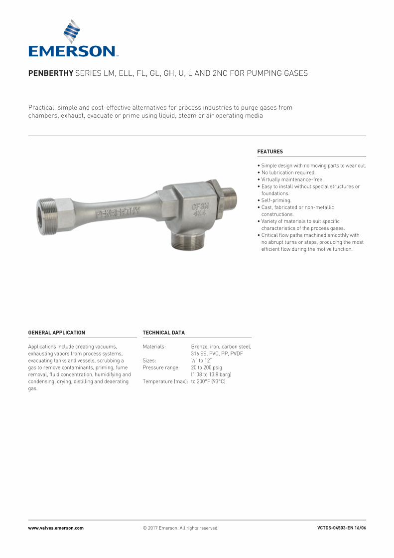
All jet pumps have three common features: inlet, suction and discharge. They function as follows:
Inlet - The operating medium (liquid, steam or air) under pressure enters the inlet and travels through the nozzle into the suction chamber. The nozzle converts the pressure of the operating medium into a high velocity stream, which passes from the discharge side of the inlet nozzle.
Suction - Pumping action begins when vapor, gases or liquid in the suction chamber are entrained by the high velocity stream emerging from the inlet nozzle, lowering the pressure in the suction chamber. The resulting action causes the liquid, gas or vapor in the suction chamber to flow toward the discharge.
TABLE 1 - MODEL SPECIFICATIONSModel LM ELL FL GL GHMotive medium Liquid Liquid Liquid Steam, gas Steam, gasMotive medium pressure range 20-200 psig
(140-1380 kPag)20-200 psig (140-1380 kPag)
20-100 psig (140-690 kPag)
60-120 psig (415-830 kPag)
20-80 psig (140-550 kPag)
Application range, inches Hg Abs(kg/cm2 Abs) 1-27 (.03-.93) 1-27 (.03-.93) 27-30 (.93-1.04) 6-30 (.18-1.04) 6.5-30 (.2-1.04)Functions Evac/Exh/Prime Evac/Exh/Prime Exh Evac/Exh/Prime Evac/Exh/Prime
TABLE 2 - MODEL SPECIFICATIONSModel U L 2NCMotive medium Steam Steam SteamMotive medium pressure range 80-200 psig (550-1380 kPag) 80-200 psig (550-1380 kPag) 100-200 psig (690-1380 kPag)Application range, inches Hg Abs(kg/cm2 Abs) 6-12 (.18-.36) 3-6 (.09-.18) 0.5-3 (.002-.09)Functions Evac/Exh Evac/Exh Evac/Exh
Models U and L are single-stage ejectors which use steam as the operating medium. They are available in 16 capacities and suction sizes from 1” to 4”.
The 2NC is a two-stage steam operated ejector with the same range of capacities and sizes as the U and L.
Suction chamber
Suction
Nozzle
Inlet
Parallel section
Diffuser Discharge
Discharge - The entrained material from the suction system mixes with the operating medium and acquires part of its energy in the parallel section. In the diffuser section, part of the velocity of the mixture is converted to a pressure greater than the suction pressure, but lower than the operating medium pressure.
3
PENBERTHY SERIES LM, ELL, FL, GL, GH, U, L AND 2NC FOR PUMPING GASESMODELS LM, ELL AND FL
PUMPING GASES USING LIQUID OPERATING MEDIUM
The LM and ELL jet pumps are used for exhausting, evacuating and priming operations where a liquid operating medium is available in a 20 to 200 psig pressure range.The maximum vacuum with closed suction is one inch Hg abs. These models are available with suction and discharge fittings ranging from ½” to 12”, depending on the type of construction.
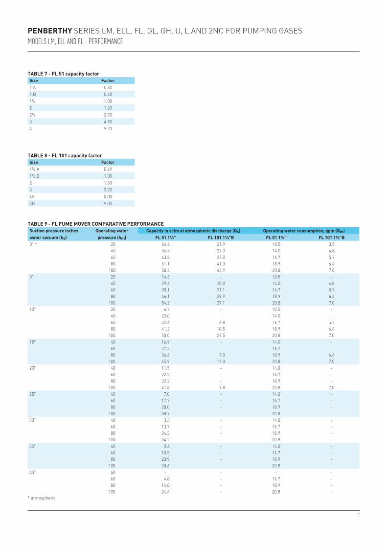
Model FL ‘fume movers’ operate in facilities where the liquid operating medium is available in the 20 to 100 PSIG range. They are identical in principle to the LM and ELL units but differ in their ‘water consumption to capacity’ ratio. Where the ELL Model requires more than 2 gpm of operating fluid for each scfm of air pumped, the FL with 2 gpm can pump approximately 14 scfm of air. The other distinguishing factor is the capacity of the FL models to move large volumes of air at a suction pressure just slightly below atmospheric.
The ELL is better suited for moving air at a suction pressure of ½ to 1/10 atmospheric pressure - about 13 times the vacuum of the FL fume mover.
FL models are available with suction and discharge fittings ranging from ½” to 4” and nozzle size ranging from ½ to 3, depending on the type of unit selected.
TABLE 3 - MODEL CONSTRUCTION DATAModel LM, ELL Standard materials FL Standard materialsSizes available ½ A-4" Cast: Low lead bronze, iron, C. steel, 316 STS 1”A - 4”B Cast: Iron, carbon steel, 316 STS
4" and up Fabricated: Carbon steel, 316 STS½ A-3" Non-Metallic: PVC, PP, PVDF (Kynar®)
NOTEKynar® is a registered trademark of Arkema Inc.
4
20 25" 24 13 15 8.3 59 32 34 19 21 11 12.00 6.4 7.10 3.9 3.90 2.10 2.20 1.20 1.20 0.66 17.5 17.220" 87 50 55 32 215 123 125 72 76 43 43.00 24.0 26.00 15.0 14.00 8.20 8.20 4.70 4.40 2.50 18.4 18.115" 180 107 114 68 448 264 260 154 157 93 88.00 52.0 54.00 32.0 30.00 18.00 17.00 10.00 9.10 5.40 19.2 18.810" - - - - 826 - 481 - 291 - - - 100.00 - 55.00 - 31.00 - 17.00 - 20.0 -
40 25" 8.3 6 5.3 3.8 21 15 12 8.7 7.3 5.2 4.10 2.9 2.50 1.8 1.40 0.99 0.79 0.57 0.42 0.30 24.2 23.020" 33 22 21 14 83 55 48 32 29 19 16.00 11.0 10.00 6.7 5.60 3.70 3.20 2.10 1.70 1.10 24.8 23.615" 83 50 53 32 208 124 121 72 73 43 41.00 24.0 25.00 15.0 14.00 8.20 7.90 4.70 4.20 2.50 25.4 24.210" 157 90 100 57 392 223 228 130 138 78 77.00 44.0 47.00 27.0 26.00 15.00 15.00 8.50 8.00 4.50 26.0 24.75" 320 163 204 104 793 405 461 236 279 143 - 80.0 96.00 49.0 53.00 27.00 30.00 15.00 16.00 8.30 26.6 25.3
60 25" 3.7 4.7 2.3 3 91 12 5.3 6.7 3.2 4.1 1.80 2.3 1.10 1.4 0.60 0.77 0.35 0.44 0.18 0.24 29.4 27.320" 17 14 11 9.1 41 36 24 21 14 12 8.10 7.0 5.00 4.3 2.70 2.40 1.60 1.30 0.84 0.72 30.0 27.815" 43 30 28 19 110 74 64 43 39 26 22.00 15.0 13.00 8.9 7.30 4.90 4.20 2.80 2.20 1.50 30.5 28.310" 97 50 62 32 240 124 139 72 84 44 47.00 24.0 29.00 15.0 16.00 8.20 9.10 4.70 4.90 2.50 30.9 28.75" 207 87 132 55 512 215 298 125 180 76 - 43.0 62.00 26.0 34.00 14.00 19.00 8.20 10.00 4.40 31.4 29.2
80 25" 2.3 3.7 1.5 2.3 5.8 9.1 3.4 5.3 2 3.2 1.10 1.8 0.70 1.1 0.38 0.60 0.22 0.35 0.11 0.18 33.8 30.920" 11 11 7 7 27 27 15.9 16 9.6 9.5 5.40 5.3 3.30 3.3 1.80 1.80 1.00 1.00 0.55 0.55 34.2 31.315" 26 22 17 14 64 54 37.5 31 23 19 13.00 11.0 7.80 6.5 4.30 3.60 2.40 2.00 1.30 1.10 34.7 31.710" 60 37 38 23 153 91 89 53 54 31 30.00 17.0 18.00 11.0 10.00 5.90 5.80 3.40 3.10 1.80 35.1 32.15" 143 60 91 38 355 149 207 87 125 54 70.00 30.0 43.00 18.0 24.00 10.00 13.00 5.80 7.20 3.10 35.6 32.5
100 25" 2.2 3.3 1.4 2.1 5.4 8.3 3.1 4.8 1.9 2.9 1.10 1.6 0.65 1.0 0.36 0.55 0.20 0.31 0.11 0.17 37.7 34.020" 7.7 9 4.9 5.7 19 22 11 13 6.7 7.9 3.70 4.4 2.30 2.7 1.30 1.50 0.72 0.86 0.39 0.46 38.1 34.415" 19 18 12 11 48 44 28 25 17 15 9.50 8.7 5.80 5.3 3.20 2.90 1.80 1.70 0.98 0.90 38.5 34.710" 40 29 25 19 99 73 58 42 35 25 20.00 14.0 12.00 8.8 6.60 4.80 3.80 2.80 2.00 1.50 38.9 35.15" 100 50 64 32 249 124 145 72 88 44 49.00 25.0 30.00 15.0 17.00 8.30 9.50 4.70 5.10 2.50 39.3 35.4
140 25" 2 2.7 1.3 1.7 4.9 6.6 2.9 3.8 1.7 2.3 0.98 1.3 0.60 0.8 0.33 0.44 0.19 0.25 0.10 0.13 44.5 39.420" 4.7 7 3 4.5 12 17 6.7 10 4.1 6.2 2.30 3.5 1.40 2.1 0.77 1.20 0.44 0.68 0.24 0.36 44.8 39.615" 11 13 7.2 8.5 28 33 16 19 9.6 12 5.50 6.6 3.40 4.0 1.90 2.20 1.10 1.30 0.57 0.68 45.2 40.010" 24 23 15 14 59 56 35 33 21 20 12.00 11.0 7.20 6.8 4.00 3.70 2.30 2.10 1.20 1.10 45.5 40.25" 47 40 30 26 118 99 69 58 41 34 23.00 19.0 14.00 12.0 7.90 6.40 4.50 3.70 2.40 2.00 45.9 40.6
PENBERTHY SERIES LM, ELL, FL, GL, GH, U, L AND 2NC FOR PUMPING GASESMODELS LL, LM, LH
PUMPING GASES USING LIQUID OPERATING MEDIUM
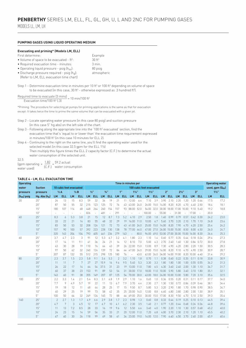
Evacuating and priming* (Models LM, ELL)First determine: Example• Volume of space to be evacuated - ft3: 30 ft3
• Required evacuation time - minutes: 3 min.• Operating liquid pressure - psig (hm): 80 psig• Discharge pressure required - psig (hd): atmospheric (Refer to LM, ELL evacuation time chart)
Step 1 - Determine evacuation time in minutes per 10 ft3 or 100 ft3 depending on volume of space to be evacuated (in this case, 30 ft3 - otherwise expressed as .3 hundred ft3).
Required time to evacuate (3 mins) = 10 min/100 ft3
Evacuation time/100 ft3 (.3)
*Priming: The procedure for selecting jet pumps for priming applications is the same as that for evacuation except: It takes twice the time to prime the same volume that can be evacuated with a given jet.
Step 2 - Locate operating water pressure (in this case 80 psig) and suction pressure (in this case 5” hg abs) on the left side of the chart.
Step 3 - Following along the appropriate line into the ‘100 ft3 evacuated’ section, find the evacuation time that’s ‘equal to or lower than’ the evacuation time requirement expressed in minutes/100 ft3 (in this case 10 minutes for ELL 2).
Step 4 - Continuing to the right on the same line, you’ll find the operating water used for the selected model (in this case 32.5 gpm for the ELL 1½)
Then multiply this figure times the ELL 2 capacity factor (C.F.) to determine the actual water consumption of the selected unit.
32.5 1.82(gpm operating × (C.F.)
= 59.2 actual
water used) water consumption
TABLE 4 - LM, ELL EVACUATION TIMEOperating water pressure (hm) psig
Suction pressure Hg. Abs (hs)
Time in minutes per Operating water used, gpm (Qm)10 cubic feet evacuated 100 cubic feet evacuated
½ A ½ B ½” ¾” 1” 1¼” 1½” 2” 2½” 3” 1½”LM ELL LM ELL LM ELL LM ELL LM ELL LM ELL LM ELL LM ELL LM ELL LM ELL LM ELL
5
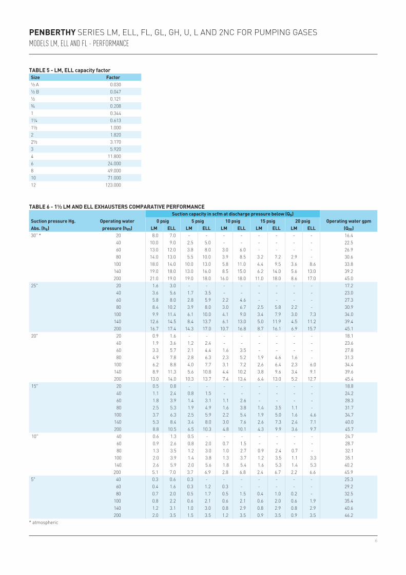
Exhausting First determine: ExampleSuction load - scfm air (Qs): 1.3 scfmSuction pressure - inches Hg abs (hs): 15”Operating liquid pressure, psig (hm): 60 psigDischarge pressure, psig (hd): 5 psig(Refer to FL exhauster and 1½ LM and ELL exhauster comparative performance chart.)
Step 1 - Locate appropriate suction pressure (in this case 15”) on left side of chart and the line that applies to existing water pressure (in this case 60 psig).
Step 2 - Read across the 60 psig line to the 5 psig discharge pressure column noting LM suction capacity: 1.4 scfm ELL suction capacity: 3.1 scfm
Step 3 - Following along the same line you’ll note Operating water used: 28.3 gpm
Step 4 - Since the ELL 1½ was the unit with the greater suction capacity in comparison to our requirement, we’ll use it in computing the ideal capacity factor (C.F.)
PENBERTHY SERIES LM, ELL, FL, GL, GH, U, L AND 2NC FOR PUMPING GASESMODELS LM, ELL AND FL
Desired capacity (1.3 scfm) = .419Suction capacity - ELL 1½ (3.1 scfm) (ideal C.F.)
Then using the capacity factor chart, find the size unit that provides a capacity factor that’s equal to or greater than .419 (ideal C.F.)
The actual capacity of the selected unit is then determined by multiplying:
3.1 .613(ELL 1½ scfm x (ELL 1¼ = 1.90 scfmper chart) capacity factor)
Step 5 - To determine water consumption of the selected unit, multiply:
28.3 .613(gpm operating x (Selected = 17.3 gpmwater used) unit C.F.)
Step 6 - In checking the capacity and consumption of the other unit considered, we find that the LM 1½, with a capacity of 1.4 scfm, has a water consumption rate of 28.3 gpm. It then becomes obvious that the ELL 1¼ is the best unit for this application as it delivers the greatest capacity with the least volume of water consumed.
Step 7 - (FL models only) - The connecting discharge line must be sized to handle both the operating liquid and entrained air without producing more than a few inches of water discharge pressure. If this cannot be done, a box, tank or separator should be provided at the discharge end to separate non-condensable washed gases from the liquid and to vent washed gases to the atmosphere.
6
½ A 0.030½ B 0.047½ 0.121¾ 0.2081 0.3441¼ 0.6131½ 1.0002 1.8202½ 3.1703 5.9204 11.8006 24.0008 49.00010 71.00012 123.000
30" * 20 8.0 7.0 - - - - - - - - 16.440 10.0 9.0 2.5 5.0 - - - - - - 22.560 13.0 12.0 3.8 8.0 3.0 6.0 - - - - 26.980 14.0 13.0 5.5 10.0 3.9 8.5 3.2 7.2 2.9 - 30.6
100 18.0 14.0 10.0 13.0 5.8 11.0 4.4 9.5 3.6 8.6 33.8140 19.0 18.0 13.0 16.0 8.5 15.0 6.2 14.0 5.6 13.0 39.2200 21.0 19.0 19.0 18.0 16.0 18.0 11.0 18.0 8.6 17.0 45.0
25" 20 1.6 3.0 - - - - - - - - 17.240 3.6 5.6 1.7 3.5 - - - - - - 23.060 5.8 8.0 2.8 5.9 2.2 4.6 - - - - 27.380 8.4 10.2 3.9 8.0 3.0 6.7 2.5 5.8 2.2 - 30.9
100 9.9 11.4 6.1 10.0 4.1 9.0 3.4 7.9 3.0 7.3 34.0140 12.6 14.5 8.4 13.7 6.1 13.0 5.0 11.9 4.5 11.2 39.4200 16.7 17.4 14.3 17.0 10.7 16.8 8.7 16.1 6.9 15.7 45.1
20" 20 0.9 1.6 - - - - - - - - 18.140 1.9 3.6 1.2 2.4 - - - - - - 23.660 3.3 5.7 2.1 4.4 1.6 3.5 - - - - 27.880 4.9 7.8 2.8 6.3 2.3 5.2 1.9 4.6 1.6 - 31.3
100 6.2 8.8 4.0 7.7 3.1 7.2 2.6 6.4 2.3 6.0 34.4140 8.9 11.3 5.6 10.8 4.4 10.2 3.8 9.6 3.4 9.1 39.6200 13.0 14.0 10.3 13.7 7.4 13.4 6.4 13.0 5.2 12.7 45.4
15" 20 0.5 0.8 - - - - - - - - 18.840 1.1 2.4 0.8 1.5 - - - - - - 24.260 1.8 3.9 1.4 3.1 1.1 2.6 - - - - 28.380 2.5 5.3 1.9 4.9 1.6 3.8 1.4 3.5 1.1 - 31.7
100 3.7 6.3 2.5 5.9 2.2 5.4 1.9 5.0 1.6 4.6 34.7140 5.3 8.4 3.4 8.0 3.0 7.6 2.6 7.3 2.4 7.1 40.0200 8.8 10.5 6.5 10.3 4.8 10.1 4.3 9.9 3.6 9.7 45.7
10" 40 0.6 1.3 0.5 - - - - - - - 24.760 0.9 2.6 0.8 2.0 0.7 1.5 - - - - 28.780 1.3 3.5 1.2 3.0 1.0 2.7 0.9 2.4 0.7 - 32.1
100 2.0 3.9 1.4 3.8 1.3 3.7 1.2 3.5 1.1 3.3 35.1140 2.6 5.9 2.0 5.6 1.8 5.4 1.6 5.3 1.4 5.3 40.2200 5.1 7.0 3.7 6.9 2.8 6.8 2.4 6.7 2.2 6.6 45.9
5" 40 0.3 0.6 0.3 - - - - - - - 25.360 0.4 1.6 0.3 1.2 0.3 - - - - - 29.280 0.7 2.0 0.5 1.7 0.5 1.5 0.4 1.0 0.2 - 32.5
100 0.8 2.2 0.6 2.1 0.6 2.1 0.6 2.0 0.6 1.9 35.4140 1.2 3.1 1.0 3.0 0.8 2.9 0.8 2.9 0.8 2.9 40.6200 2.0 3.5 1.5 3.5 1.2 3.5 0.9 3.5 0.9 3.5 46.2
PENBERTHY SERIES LM, ELL, FL, GL, GH, U, L AND 2NC FOR PUMPING GASESMODELS LM, ELL AND FL - PERFORMANCE
TABLE 5 - LM, ELL capacity factorSize Factor
TABLE 6 - 1½ LM AND ELL EXHAUSTERS COMPARATIVE PERFORMANCE
Suction pressure Hg. Abs. (hs)
Operating water pressure (hm)
Suction capacity in scfm at discharge pressure below (Qs)Operating water gpm
(Qm)0 psig 5 psig 10 psig 15 psig 20 psig
LM ELL LM ELL LM ELL LM ELL LM ELL
* atmospheric
7
1 A 0.301 B 0.481½ 1.002 1.602½ 2.703 4.904 9.20
1½ A 0.691½ B 1.002 1.603 3.204A 5.004B 9.00
0" * 20 24.6 21.9 10.5 3.540 36.5 29.3 14.0 4.860 43.8 37.0 16.7 5.780 51.1 41.3 18.9 6.4
100 58.6 46.9 20.8 7.05" 20 14.6 - 10.5 -
40 29.6 10.0 14.0 4.860 38.1 21.1 16.7 5.780 46.1 29.9 18.9 6.4
100 54.2 37.1 20.8 7.010" 20 6.7 - 10.5 -
40 23.0 - 14.0 -60 32.6 6.8 16.7 5.780 41.2 18.5 18.9 6.4
100 50.0 27.5 20.8 7.015" 40 16.9 - 14.0 -
60 27.2 - 16.7 -80 36.6 7.0 18.9 6.4
100 45.9 17.0 20.8 7.020" 40 11.5 - 14.0 -
60 22.2 - 16.7 -80 32.2 - 18.9 -
100 41.8 7.8 20.8 7.025" 40 7.0 - 14.0 -
60 17.7 - 16.7 -80 28.0 - 18.9 -
100 38.7 - 20.8 -30" 40 3.3 - 14.0 -
60 13.7 - 16.7 -80 24.3 - 18.9 -
100 34.2 - 20.8 -35" 40 0.4 - 14.0 -
60 10.5 - 16.7 -80 20.9 - 18.9 -
100 30.6 - 20.8 -45" 40 - - - -
60 4.8 - 16.7 -80 14.8 - 18.9 -
100 24.4 - 20.8 -
PENBERTHY SERIES LM, ELL, FL, GL, GH, U, L AND 2NC FOR PUMPING GASESMODELS LM, ELL AND FL - PERFORMANCE
TABLE 7 - FL 51 capacity factorSize Factor
TABLE 8 - FL 101 capacity factorSize Factor
TABLE 9 - FL FUME MOVER COMPARATIVE PERFORMANCESuction pressure inches water vacuum (hs)
Operating water pressure (hm)
Capacity in scfm at atmospheric discharge (Qs) Operating water consumption, gpm (Qm)FL 51 1½” FL 101 1½”B FL 51 1½” FL 101 1½”B
* atmospheric
8
AB
C
AB
C
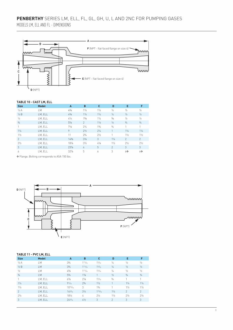
½ A LM 4⅜ 1½ 1¼ ¼ ½ ½½ B LM, ELL 4⅜ 1½ 1¼ ¼ ½ ½½ LM, ELL 4½ 1⅝ 1¼ ⅜ ½ ½¾ LM, ELL 5⅞ 2 1½ ½ ¾ ¾1 LM, ELL 7⅛ 2¼ 1¾ ¾ 1 11¼ LM, ELL 9 2½ 2¼ 1 1¼ 1¼1½ LM, ELL 11 2¾ 2½ 1 1½ 1½2 LM, ELL 14⅜ 3⅛ 3 1¼ 2 22½ LM, ELL 18⅛ 3½ 4⅛ 1½ 2½ 2½3 LM, ELL 23⅞ 4 5 2 3 34 LM, ELL 32⅞ 5 6 3 4❖ 4❖
½ A LM 3¾ 1 11/16 1 5/16 ¼ ½ ½½ B LM 3¾ 1 11/16 1 5/16 ¼ ½ ½½ LM 4⅝ 1 11/16 1 5/16 ¼ ½ ½¾ LM 5¾ 1⅞ 1 ½ ¾ ¾1 LM, ELL 6⅞ 2⅛ 1 5/16 ¾ 1 11¼ LM, ELL 9 1/16 2¾ 1½ 1 1¼ 1¼1½ LM, ELL 10 15/16 3 1¾ 1 1½ 1½2 LM, ELL 14 3/16 3½ 1 15/16 1¼ 2 22½ LM, ELL 18½ 4 2½ 1½ 2½ 2½3 LM, ELL 24 3/16 4½ 3 2 3 3
PENBERTHY SERIES LM, ELL, FL, GL, GH, U, L AND 2NC FOR PUMPING GASESMODELS LM, ELL AND FL - DIMENSIONS
TABLE 10 - CAST LM, ELLSize Model A B C D E F
❖ Flange. Bolting corresponds to ASA 150 lbs.
F (NPT - flat faced flange on size 4)
E (NPT - flat faced flange on size 4)
D (NPT)
TABLE 11 - PVC LM, ELLSize Model A B C D E F
D (NPT)
E (NPT)
F (NPT)
9
AB
C
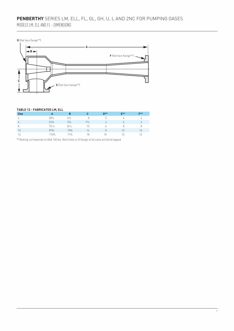
4 38¼ 5¼ 8 3 4 46 52⅞ 5⅞ 9½ 4 6 68 74 7/16 8 7/16 13 6 8 810 87⅜ 10⅜ 14 8 10 1012 110¾ 11¾ 18 10 12 12
PENBERTHY SERIES LM, ELL, FL, GL, GH, U, L AND 2NC FOR PUMPING GASESMODELS LM, ELL AND FL - DIMENSIONS
TABLE 12 - FABRICATED LM, ELLSize A B C D** E** F**
** Bolting corresponds to ASA 150 lbs. Bolt holes in D flange of all sizes are blind tapped
D (flat face flange**)
E (flat face flange**)
F (flat face flange**)
10
AB
C
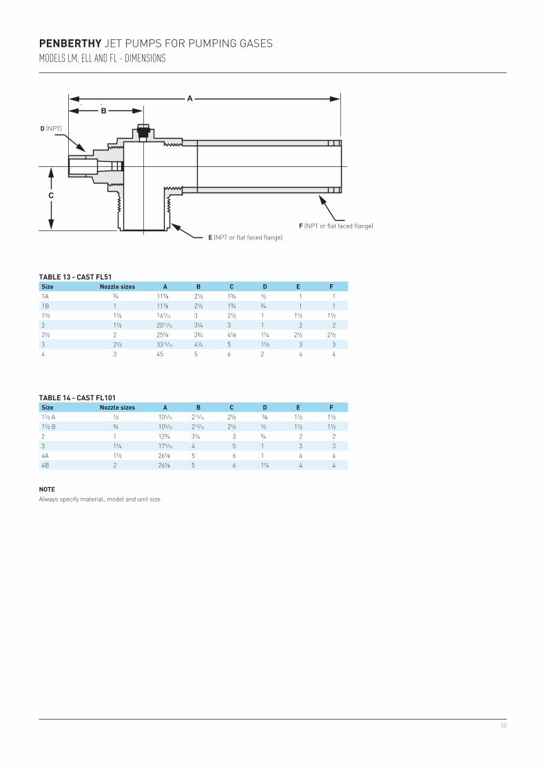
1A ¾ 11⅞ 2½ 1¾ ½ 1 11B 1 11⅞ 2½ 1¾ ¾ 1 11½ 1¼ 169/16 3 2½ 1 1½ 1½2 1½ 20 11/16 3¼ 3 1 2 22½ 2 25⅞ 3¾ 4⅛ 1¼ 2½ 2½3 2½ 33 15/16 4¼ 5 1½ 3 34 3 45 5 6 2 4 4
1½ A ½ 10 5/16 2 13/16 2½ ⅜ 1½ 1½1½ B ¾ 10 5/16 2 13/16 2½ ½ 1½ 1½2 1 12¾ 3¼ 3 ¾ 2 23 1¼ 17 9/16 4 5 1 3 34A 1½ 26⅛ 5 6 1 4 44B 2 26⅛ 5 6 1¼ 4 4
PENBERTHY JET PUMPS FOR PUMPING GASESMODELS LM, ELL AND FL - DIMENSIONS
TABLE 13 - CAST FL51Size Nozzle sizes A B C D E F
TABLE 14 - CAST FL101Size Nozzle sizes A B C D E F
NOTEAlways specify material, model and unit size.
F (NPT or flat faced flange)
E (NPT or flat faced flange)
D (NPT)
11
PENBERTHY SERIES LM, ELL, FL, GL, GH, U, L AND 2NC FOR PUMPING GASESMODELS GL, GH
PUMPING GASES USING STEAM OR AIR OPERATING MEDIUM
Series G jet pumps include the GL and GH models. They are used for exhausting, evacuating and priming applications.
Model GL uses operating steam or air from 60 to 120 psig. The maximum vacuum with closed suction is 6” Hg abs.
Model GH uses operating steam or air from 20 to 80 psig. The maximum vacuum with closedsuction is 6½” Hg abs.
Each model is available in 15 sizes from ½” to 12” suction and discharge. Units are cast construction in sizes ½ through 6. Sizes 4 through 12 are available with fabricated construction. Certain sizes of units are also available in PVC or other polymer constructions.
TABLE 15 - MODEL CONSTRUCTION DATAModel GL, GH Standard materialsSizes Available ½A-4" Cast: Low lead bronze, iron, C. steel, 316 STS
4" and up Fabricated: Carbon steel, 316 STS½A-3" Non-Metallic: PVC, PP, PVDF (Kynar™)
The capacities of both models are slightly higher when using air as the operating medium instead of steam. The following information is required for selection of both the GL and GH models for exhausting, evacuating and priming:
Exhausting• Suction load, standard cubic feet per minute (scfm) air (Qs)*• Suction pressure, inches Hg. abs. (hs)• Operating steam or air pressure, psig (hm)• Discharge pressure required, psig (hd)* For suction loads other than air, refer to dry air equivalent section on page 22.
Evacuating• Suction load, in cubic feet of space to be evacuated• Required time to evacuate, in minutes• Operating steam or air pressure, psig (hm)• Final suction pressure, inches Hg abs. (hs)• Discharge pressure required, psig (hd)
PrimingThe selection procedure for ejectors in priming applications is the same as that for evacuation, except: The evacuation time must be doubled for priming applications because the priming capacity of any given ejector is half that of the evacuating capacity.
NOTEAlways specify material, model and unit size when ordering.
12
PENBERTHY SERIES LM, ELL, FL, GL, GH, U, L AND 2NC FOR PUMPING GASESMODELS GL, GH
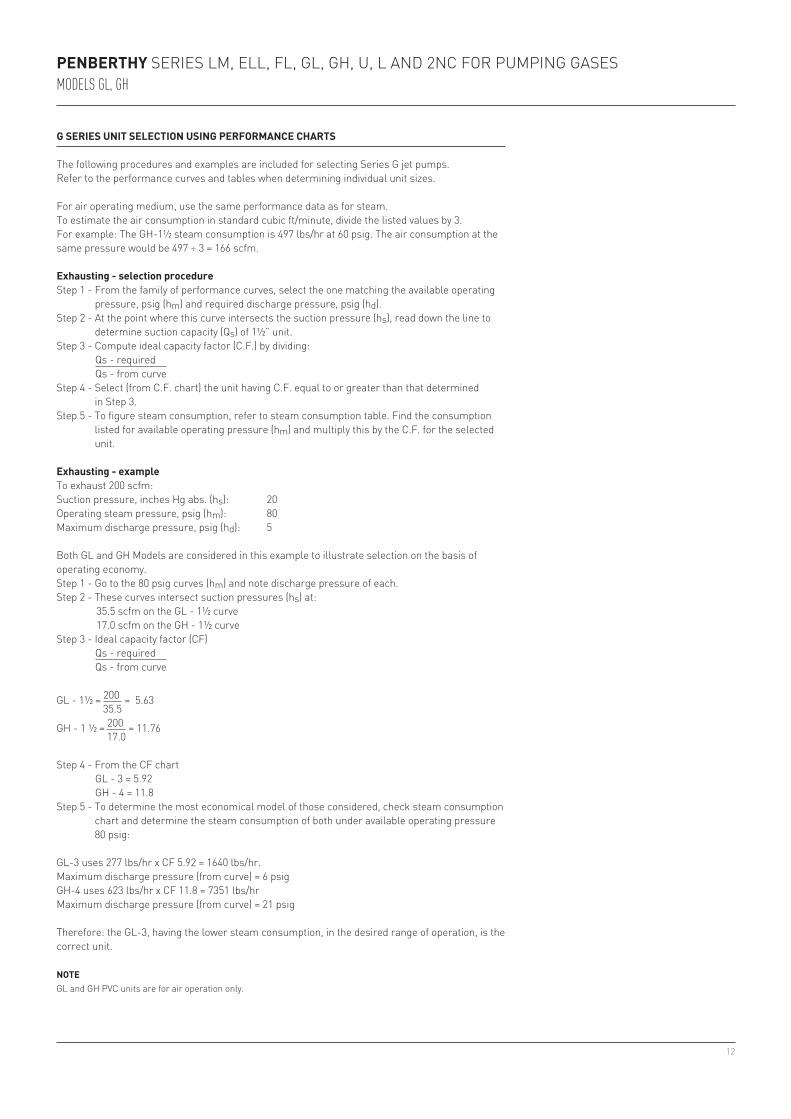
G SERIES UNIT SELECTION USING PERFORMANCE CHARTS
The following procedures and examples are included for selecting Series G jet pumps.Refer to the performance curves and tables when determining individual unit sizes.
For air operating medium, use the same performance data as for steam.To estimate the air consumption in standard cubic ft/minute, divide the listed values by 3.For example: The GH-1½ steam consumption is 497 lbs/hr at 60 psig. The air consumption at thesame pressure would be 497 ÷ 3 = 166 scfm.
Exhausting - selection procedureStep 1 - From the family of performance curves, select the one matching the available operating
pressure, psig (hm) and required discharge pressure, psig (hd).Step 2 - At the point where this curve intersects the suction pressure (hs), read down the line to
determine suction capacity (Qs) of 1½” unit.Step 3 - Compute ideal capacity factor (C.F.) by dividing: Qs - required Qs - from curveStep 4 - Select (from C.F. chart) the unit having C.F. equal to or greater than that determined
in Step 3.Step 5 - To figure steam consumption, refer to steam consumption table. Find the consumption
listed for available operating pressure (hm) and multiply this by the C.F. for the selected unit.
Exhausting - exampleTo exhaust 200 scfm:Suction pressure, inches Hg abs. (hs): 20Operating steam pressure, psig (hm): 80Maximum discharge pressure, psig (hd): 5
Both GL and GH Models are considered in this example to illustrate selection on the basis of operating economy.Step 1 - Go to the 80 psig curves (hm) and note discharge pressure of each.Step 2 - These curves intersect suction pressures (hs) at: 35.5 scfm on the GL - 1½ curve 17.0 scfm on the GH - 1½ curveStep 3 - Ideal capacity factor (CF) Qs - required Qs - from curve
GL - 1½ = 200 = 5.63 35.5
GH - 1 ½ = 200 = 11.76 17.0
Step 4 - From the CF chart GL - 3 = 5.92 GH - 4 = 11.8Step 5 - To determine the most economical model of those considered, check steam consumption
chart and determine the steam consumption of both under available operating pressure 80 psig:
GL-3 uses 277 lbs/hr x CF 5.92 = 1640 lbs/hr.Maximum discharge pressure (from curve) = 6 psigGH-4 uses 623 lbs/hr x CF 11.8 = 7351 lbs/hrMaximum discharge pressure (from curve) = 21 psig
Therefore: the GL-3, having the lower steam consumption, in the desired range of operation, is the correct unit.
NOTEGL and GH PVC units are for air operation only.
13
PENBERTHY SERIES LM, ELL, FL, GL, GH, U, L AND 2NC FOR PUMPING GASESMODELS GL, GH
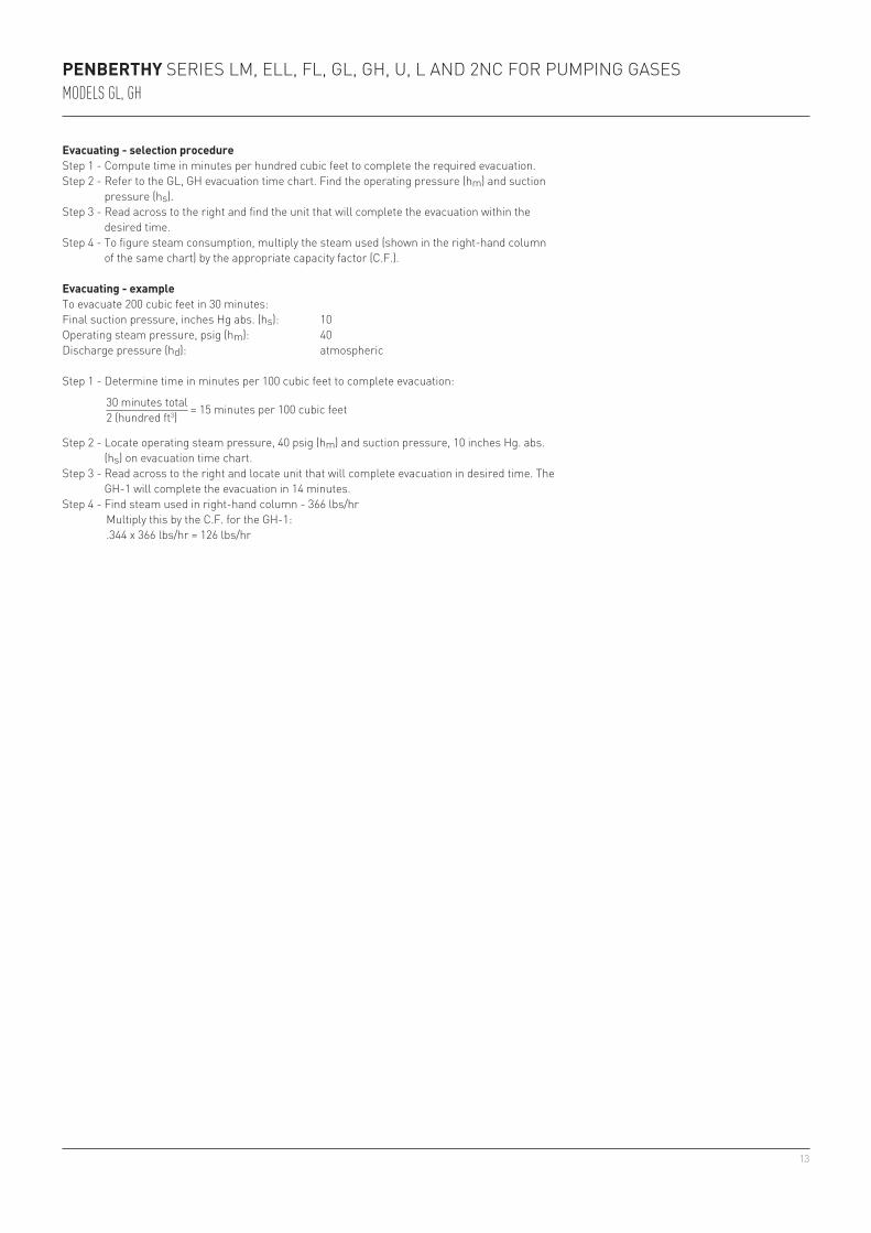
Evacuating - selection procedureStep 1 - Compute time in minutes per hundred cubic feet to complete the required evacuation.Step 2 - Refer to the GL, GH evacuation time chart. Find the operating pressure (hm) and suction
pressure (hs).Step 3 - Read across to the right and find the unit that will complete the evacuation within the
desired time.Step 4 - To figure steam consumption, multiply the steam used (shown in the right-hand column
of the same chart) by the appropriate capacity factor (C.F.).
Evacuating - exampleTo evacuate 200 cubic feet in 30 minutes:Final suction pressure, inches Hg abs. (hs): 10Operating steam pressure, psig (hm): 40Discharge pressure (hd): atmospheric
Step 1 - Determine time in minutes per 100 cubic feet to complete evacuation:
30 minutes total = 15 minutes per 100 cubic feet 2 (hundred ft3)
Step 2 - Locate operating steam pressure, 40 psig (hm) and suction pressure, 10 inches Hg. abs. (hs) on evacuation time chart.
Step 3 - Read across to the right and locate unit that will complete evacuation in desired time. The GH-1 will complete the evacuation in 14 minutes.
Step 4 - Find steam used in right-hand column - 366 lbs/hr Multiply this by the C.F. for the GH-1: .344 x 366 lbs/hr = 126 lbs/hr
14
30 25" - 2.4 - 1.5 - 6.0 - 3.5 - 2.1 - 1.20 - 0.73 - 0.40 - 0.23 - 0.12 - 30120" - 4.7 - 3.0 - 12.0 - 6.7 - 4.1 - 2.30 - 1.40 - 0.77 - 0.44 - 0.24 - 30115" - 8.7 - 5.5 - 21.0 - 12.0 - 7.5 - 4.20 - 2.60 - 1.40 - 0.82 - 0.44 - 30110" - 15.0 - 9.6 - 37.0 - 22.0 - 13.0 - 7.30 - 4.50 - 2.50 - 1.40 - 0.76 - 301
40 25" - 1.7 - 1.1 - 4.1 - 2.4 - 1.4 - 0.81 - 0.50 - 0.27 - 0.16 - 0.08 - 36620" - 4.0 - 2.5 - 9.9 - 5.8 - 3.5 - 2.00 - 1.20 - 0.66 - 0.38 - 0.20 - 36615" - 8.3 - 5.3 - 21.0 - 12.0 - 7.3 - 4.10 - 2.50 - 1.40 - 0.79 - 0.42 - 36610" - 15.7 - 10.0 - 39.0 - 23.0 - 14.0 - 7.70 - 4.70 - 2.60 - 1.50 - 0.79 - 366
60 25" 1.0 1.7 0.64 1.1 2.5 4.1 1.4 2.4 0.87 1.4 0.49 0.81 0.3 0.50 0.16 0.27 0.09 0.16 0.05 0.08 221 49720" 2.3 4.7 1.50 3.0 5.8 12.0 3.4 6.7 2.00 4.1 1.10 2.30 0.7 1.40 0.38 0.77 0.22 0.44 0.12 0.24 221 49715" 4.0 9.3 2.50 6.0 9.9 23.0 5.8 13.0 3.50 8.1 1.90 4.60 1.2 2.80 0.66 1.50 0.38 0.88 0.20 0.47 221 49710" 7.7 19.0 4.90 12.0 19.0 47.0 11.0 27.0 6.70 17.0 3.70 9.30 2.3 5.70 1.30 3.10 0.72 1.80 0.39 0.96 221 497
80 25" 1.0 2.0 0.64 1.3 2.5 5.0 1.4 2.9 0.87 1.7 0.49 0.98 0.3 0.60 0.16 0.33 0.09 0.19 0.05 0.10 277 62320" 2.0 5.0 1.30 3.2 5.0 12.0 2.9 7.2 1.70 4.4 0.98 2.40 0.6 1.50 0.33 0.82 0.19 0.47 0.10 0.25 277 62315" 4.0 9.7 2.50 6.2 9.9 24.0 5.8 14.0 3.50 8.4 2.00 4.70 1.2 2.90 0.66 1.60 0.38 0.91 0.20 0.49 277 62310" 8.0 20.0 5.10 13.0 20.0 50.0 11.0 29.0 7.00 17.0 3.90 9.80 2.4 6.00 1.30 3.30 0.76 1.90 0.40 1.00 277 623
100 25" 1.0 2.0 0.64 1.3 2.5 5.0 1.4 2.9 0.87 1.7 0.49 0.98 0.3 0.60 0.16 0.33 0.09 0.19 0.05 0.10 333 75020" 2.3 5.3 1.50 3.4 5.8 13.0 3.4 7.7 2.00 4.6 1.10 2.60 0.7 1.60 0.38 0.88 0.22 0.50 0.12 0.27 333 75015" 4.7 12.0 3.00 7.4 12.0 29.0 6.7 17.0 4.10 10.0 2.30 5.70 1.4 3.50 0.77 1.90 0.44 1.10 0.24 0.59 333 75010" 8.7 40.0 5.50 26.0 21.0 99.0 12.0 58.0 7.60 35.0 4.30 - 2.6 - 1.40 6.60 0.82 3.80 0.44 2.00 333 750
120 25" 1.0 - 0.64 - 2.5 - 1.4 - 0.87 - 0.49 - 0.3 - 0.16 - 0.09 - 0.05 - 390 -20" 2.7 - 1.70 - 6.6 - 3.8 - 2.30 - 1.30 - 0.8 - 0.44 - 0.25 - 0.13 - 390 -15" 5.3 - 3.40 - 13.0 - 7.7 - 4.60 - 2.60 - 1.6 - 0.88 - 0.50 - 0.27 - 390 -10" 9.0 - 5.70 - 22.0 - 13.0 - 7.80 - 4.40 - 2.7 - 1.50 - 0.85 - 0.46 - 390 -
GL 221 277 333 390 474GH 236 366 497 623 750 878 1067
½ A 0.030½ B 0.047½ 0.121¾ 0.2081 0.3441¼ 0.6131½ 1.0002 1.8202½ 3.1703 5.9204 11.8006 24.0008 49.00010 71.00012 123.000
GL 74 92 111 130 158GH 78 122 166 208 250 293 356
PENBERTHY SERIES LM, ELL, FL, GL, GH, U, L AND 2NC FOR PUMPING GASESMODELS GL, GH - PERFORMANCE
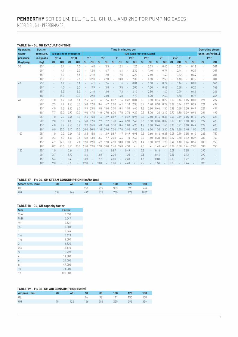
TABLE 16 - GL, GH EVACUATION TIMEOperating water pressure (hm) psig
Suction pressure, in. Hg abs
(hs)
Time in minutes per Operating steam used, lbs/hr (Qm) 10 cubic feet evacuated 100 cubic feet evacuated
½” A ½” B ½” ¾” 1” 1¼” 1½” 2” 2½” 3” 1½”GL GH GL GH GL GH GL GH GL GH GL GH GL GH GL GH GL GH GL GH GL GH
TABLE 17 - 1½ GL, GH STEAM CONSUMPTION (lbs/hr Qm)Steam pres. (hm) 20 40 60 80 100 120 150
TABLE 18 - GL, GH capacity factorSize Factor
TABLE 19 - 1½ GL, GH AIR CONSUMPTION (scfm)Air pres. (hm) 20 40 60 80 100 120 150
15
0 10 20 30 40 50 60
30
25
20
15
10
5
GH
GL
PENBERTHY SERIES LM, ELL, FL, GL, GH, U, L AND 2NC FOR PUMPING GASESMODELS GL, GH - PERFORMANCE
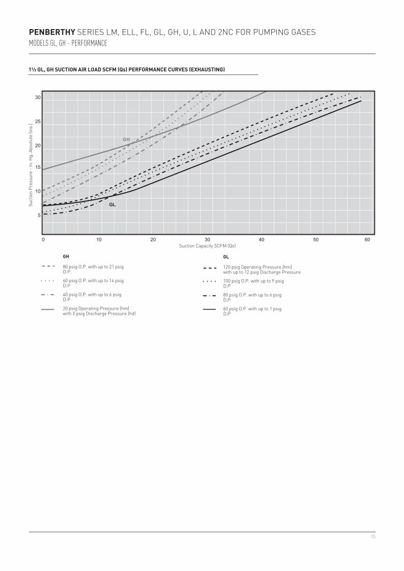
1½ GL, GH SUCTION AIR LOAD SCFM (Qs) PERFORMANCE CURVES (EXHAUSTING)
Suct
ion
Pres
sure
- In
. Hg.
Abs
olut
e (in
s.)
Suction Capacity SCFM (Qs)
GH
80 psig O.P. with up to 21 psig D.P.
60 psig O.P. with up to 14 psig D.P
40 psig O.P. with up to 6 psigD.P
20 psig Operating Pressure (hm)with 0 psig Discharge Pressure (hd)
GL
120 psig Operating Pressure (hm)with up to 12 psig Discharge Pressure
100 psig O.P. with up to 9 psigD.P
80 psig O.P. with up to 6 psigD.P
60 psig O.P. with up to 1 psigD.P
16
AB
C
AB
C
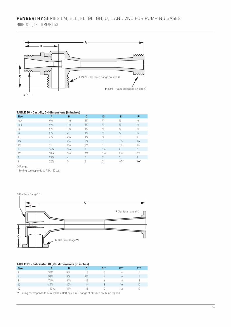
½ A 4⅜ 1½ 1¼ ¼ ½ ½½ B 4⅜ 1½ 1¼ ¼ ½ ½½ 4½ 1⅝ 1¼ ⅜ ½ ½¾ 5⅞ 2 1½ ½ ¾ ¾1 7⅛ 2¼ 1¾ ¾ 1 11¼ 9 2½ 2¼ 1 1¼ 1¼1½ 11 2¾ 2½ 1 1½ 1½2 14⅜ 3⅛ 3 1¼ 2 22½ 18⅛ 3½ 4⅛ 1½ 2½ 2½3 23⅞ 4 5 2 3 34 32⅞ 5 6 3 4❖* 4❖*
4 38¼ 5¼ 8 3 4 46 52⅞ 5⅞ 9½ 4 6 68 74 7/16 8 7/16 13 6 8 810 87⅜ 10⅜ 14 8 10 1012 110¾ 11¾ 18 10 12 12
PENBERTHY SERIES LM, ELL, FL, GL, GH, U, L AND 2NC FOR PUMPING GASESMODELS GL, GH - DIMENSIONS
TABLE 20 - Cast GL, GH dimensions (in inches)Size A B C D* E* F*
❖ Flange. * Bolting corresponds to ASA 150 lbs.
F (NPT - flat faced flange on size 4)
E (NPT - flat faced flange on size 4)
D (NPT)
TABLE 21 - Fabricated GL, GH dimensions (in inches)Size A B C D** E** F**
** Bolting corresponds to ASA 150 lbs. Bolt holes in D flange of all sizes are blind tapped.
D (flat face flange**)
E (flat face flange**)
F (flat face flange**)
17
A
B
C
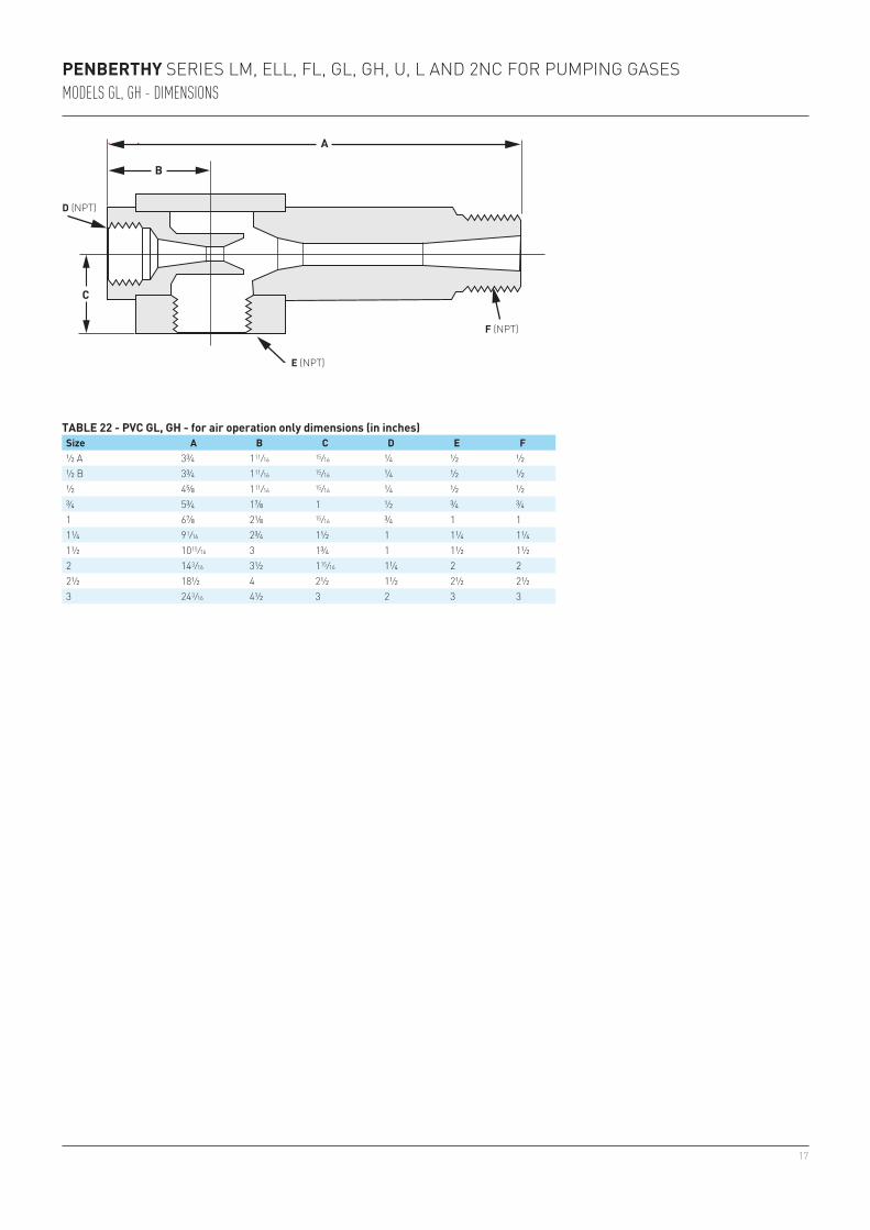
½ A 3¾ 1 11/16 15/16 ¼ ½ ½½ B 3¾ 1 11/16 15/16 ¼ ½ ½½ 4⅝ 1 11/16 15/16 ¼ ½ ½¾ 5¾ 1⅞ 1 ½ ¾ ¾1 6⅞ 2⅛ 15/16 ¾ 1 11¼ 9 1/16 2¾ 1½ 1 1¼ 1¼1½ 10 15/16 3 1¾ 1 1½ 1½2 14 3/16 3½ 1 15/16 1¼ 2 22½ 18½ 4 2½ 1½ 2½ 2½3 24 3/16 4½ 3 2 3 3
TABLE 22 - PVC GL, GH - for air operation only dimensions (in inches)Size A B C D E F
PENBERTHY SERIES LM, ELL, FL, GL, GH, U, L AND 2NC FOR PUMPING GASESMODELS GL, GH - DIMENSIONS
D (NPT)
E (NPT)
F (NPT)
18
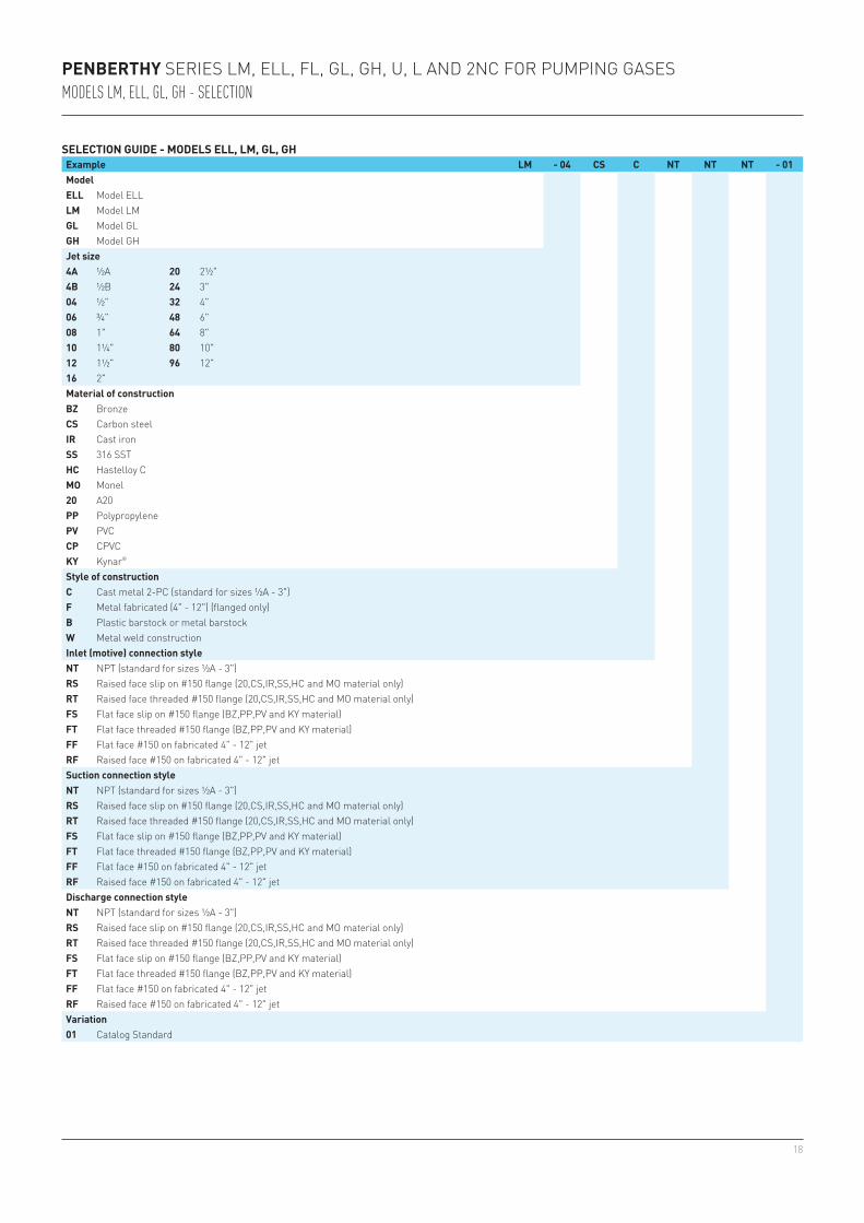
PENBERTHY SERIES LM, ELL, FL, GL, GH, U, L AND 2NC FOR PUMPING GASESMODELS LM, ELL, GL, GH - SELECTION
SELECTION GUIDE - MODELS ELL, LM, GL, GHExample LM - 04 CS C NT NT NT - 01ModelELL Model ELLLM Model LMGL Model GLGH Model GHJet size4A ½A 20 2½"4B ½B 24 3"04 ½" 32 4"06 ¾" 48 6"08 1" 64 8"10 1¼" 80 10"12 1½" 96 12"16 2"Material of constructionBZ BronzeCS Carbon steelIR Cast ironSS 316 SSTHC Hastelloy CMO Monel20 A20PP PolypropylenePV PVCCP CPVCKY Kynar®
Style of constructionC Cast metal 2-PC (standard for sizes ½A - 3")F Metal fabricated (4" - 12") (flanged only)B Plastic barstock or metal barstockW Metal weld constructionInlet (motive) connection styleNT NPT (standard for sizes ½A - 3")RS Raised face slip on #150 flange (20,CS,IR,SS,HC and MO material only)RT Raised face threaded #150 flange (20,CS,IR,SS,HC and MO material only)FS Flat face slip on #150 flange (BZ,PP,PV and KY material)FT Flat face threaded #150 flange (BZ,PP,PV and KY material)FF Flat face #150 on fabricated 4" - 12" jetRF Raised face #150 on fabricated 4" - 12" jetSuction connection styleNT NPT (standard for sizes ½A - 3")RS Raised face slip on #150 flange (20,CS,IR,SS,HC and MO material only)RT Raised face threaded #150 flange (20,CS,IR,SS,HC and MO material only)FS Flat face slip on #150 flange (BZ,PP,PV and KY material)FT Flat face threaded #150 flange (BZ,PP,PV and KY material)FF Flat face #150 on fabricated 4" - 12" jetRF Raised face #150 on fabricated 4" - 12" jetDischarge connection styleNT NPT (standard for sizes ½A - 3")RS Raised face slip on #150 flange (20,CS,IR,SS,HC and MO material only)RT Raised face threaded #150 flange (20,CS,IR,SS,HC and MO material only)FS Flat face slip on #150 flange (BZ,PP,PV and KY material)FT Flat face threaded #150 flange (BZ,PP,PV and KY material)FF Flat face #150 on fabricated 4" - 12" jetRF Raised face #150 on fabricated 4" - 12" jetVariation01 Catalog Standard
19
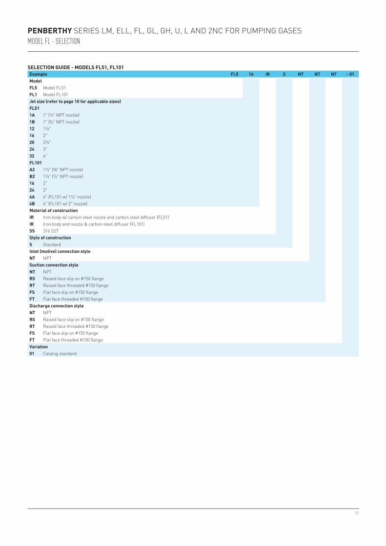
PENBERTHY SERIES LM, ELL, FL, GL, GH, U, L AND 2NC FOR PUMPING GASESMODEL FL - SELECTION
SELECTION GUIDE - MODELS FL51, FL101Example FL5 16 IR S NT NT NT - 01ModelFL5 Model FL51FL1 Model FL101Jet size (refer to page 10 for applicable sizes)FL511A 1" (½" NPT nozzle)1B 1" (¾" NPT nozzle)12 1½"16 2"20 2½"24 3"32 4"FL101A2 1½" (⅜" NPT nozzle)B2 1½" (½" NPT nozzle)16 2"24 3"4A 4" (FL101 w/ 1½" nozzle)4B 4" (FL101 w/ 2" nozzle)Material of constructionIR Iron body w/ carbon steel nozzle and carbon steel diffuser (FL51)IR Iron body and nozzle & carbon steel diffuser (FL101)SS 316 SSTStyle of constructionS StandardInlet (motive) connection styleNT NPTSuction connection styleNT NPTRS Raised face slip on #150 flange RT Raised face threaded #150 flange FS Flat face slip on #150 flange FT Flat face threaded #150 flange Discharge connection styleNT NPTRS Raised face slip on #150 flange RT Raised face threaded #150 flange FS Flat face slip on #150 flange FT Flat face threaded #150 flange Variation01 Catalog standard
20
PENBERTHY SERIES LM, ELL, FL, GL, GH, U, L AND 2NC FOR PUMPING GASESMODELS U, L, 2NC
PUMPING GASES USING STEAM OPERATING MEDIUM
Model U and L single stage ejectors are available in 16 capacities and suction sizes from 1” to 4”. Model U operates efficiently in a vacuum range of 6” to 12” Hg abs.; model L in the range of 3” to 6” Hg. abs. These ejectors are used for exhausting and evacuating applications where steam is the operating medium in the range of 80 to 200 psig.
The 2NC two stage non-condensing ejector is also available in 16 capacity ranges for similar applications in a vacuum range of ½” to 3” Hg abs. It uses steam as the operating medium in the range of 100 to 200 psig.
Nozzles supplied with U, L and 2NC ejectors are selected to match the operating steam pressure specified when units are ordered. Nozzles are available for operating steam pressures of 80 (for U and L only), 100, 120, 140, 160, 180 or 200 psig.
Steam consumption data given in charts in this section are valid for any one of these pressures.When the operating steam pressure specified falls between two of these standard pressures, the lower pressure nozzle will be supplied. Steam consumption will be slightly higher for such units unless the operating steam pressure is regulated to match that of the nozzle.
The following information is required for selection of these three steam operated models in exhausting and evacuating applications:
Exhausting• Suction load (Qs) lbs./hr. of dry air at 70°F, or dry air equivalent (DAE)
(For suction loads other than air, refer to dry air equivalent section on page 28). Air - pounds per hour Water vapor - pounds per hour Molecular weights and quantities of other suction gases - pounds per hour• Suction pressure, inches Hg abs. (hs)• Operating steam pressure, psig (hm)• Discharge pressure, psig (hd) (if greater than 1 psig, contact factory)
Evacuating• Suction load, in cubic feet of air to be evacuated Required time to evacuate, in minutes• Operating steam pressure, psig (hm)• Final suction pressure, inches Hg abs (hs)• Discharge pressure required, psig (hd)For evacuating applications using Model L or Model 2NC, contact the factory
Sizes availableEach model is available in 16 sizes from 1 inch to 4 inches suction and discharge. Sizes 1 through 3 are NPT. Size 4 is drilled in accordance with ASA 125 lbs. bolt pattern.
NOTEWhen ordering, always specify operating steam pressure, for correct nozzle sizing. Also specify material, model and unit size. For available materials, see below.
TABLE 23 - MODEL CONSTRUCTION DATAModel U, L, 2NC Standard materialsSizes available 1H-16H Cast: Carbon steel, iron body, 316 STS nozzle or all 316 STS
21
PENBERTHY SERIES LM, ELL, FL, GL, GH, U, L AND 2NC FOR PUMPING GASESMODELS U, L, 2NC
U, L, 2NC UNIT SELECTION USING PERFORMANCE CHARTS
The following procedures and examples are included for selecting U, L and 2NC ejectors. Refer to the performance curves and tables to determine individual unit sizes.
Exhausting - selection procedureRefer to U, L performance curves on pages 23 and 24.
Step 1 - Determine the unit having a suction pressure within the application range.Step 2 - Determine the capacity of the selected unit using the following procedure: a. Refer to the required suction pressure (hs) in the left-hand column. b. Read across to the operating steam pressure curve (hm). Read down this line and note the suction capacity at the bottom of the chart.NOTEBoth U and L curves are drawn for U-4 and L-4 units. Capacity factors are used to determine capacities of all other units.
Step 3 - Calculate the ideal capacity factor:
Ideal C.F. = Desired capacity Capacity from curve
Step 4 - Choose the unit with the capacity factor equal to or greater than the ideal.Step 5 - Refer to the capacity factor chart and note the operating steam consumption (Qm)
for the selected unit.The selection procedure for Model 2NC is identical to that for models U and L. Use 2NC performance curves and steam consumption chart.
Exhausting - ExampleTo exhaust 55 pounds of 70°F dry air per hour:Suction pressure, inches Hg abs (hs): 6Operating steam pressure, psig (hm): 160Discharge pressure, psig (hd): 1
Step 1 - Consider both U-4 and L-4 units based on suction pressure of 6 inches Hg abs.Step 2 - Starting at 6 (hs) on curve, read across to required operating steam pressure (hm). Read
down this vertical line and note suction capacity (Qs) at bottom. U-4 capacity is 84 lbs. per hour L-4 capacity is 85 lbs. per hourStep 3 - Calculate ideal capacity factor: Desired capacity = for U − 4 55lbs / hr = .655 Capacity from curve 84 = for L − 4 55lbs / hr = .647 85Step 4 - Choose the exact unit size having a C.F. equal to or greater than the ideal. Both models U-3 and L-3 have a C.F. of .694. U-3 Capacity = .694 x 84 (from Step 2) = 58.2 lbs/hr L-3 Capacity = .694 x 85 = 58.9 lbs/hrThis particular example illustrates the close performance characteristics of both U and L models at the suction pressure of 6” Hg abs. In this case, the model U is operating in the lower end of its application range and its performance improves at suction pressures above 6. The model L, however, is operating in the upper extreme of the application range and performance improves at suction pressures below 6.Step 5 - Note operating steam consumption (Qm) on capacity factor chart. Model U-3 and L-3
steam consumption = 195 lbs/hr.
22
PENBERTHY SERIES LM, ELL, FL, GL, GH, U, L AND 2NC FOR PUMPING GASESMODELS U, L, 2NC
U, L, 2NC UNIT SELECTION USING PERFORMANCE CHARTS
Evacuating - selection procedureRefer to U evacuation time chart.Step 1 - Figure evacuation time in minutes per hundred cubic feet.Step 2 - Go to the left-hand column in table, final suction pressure (hs). Read across to find
evacuation time equal to or less than that determined in Step 1. Read to the top of the table and note unit number.
Step 3 - Read steam consumption of unit selected off capacity factor chart.
Evacuating - exampleTo evacuate 3000 cubic foot vessel full of air at atmospheric pressure:Operating steam pressure, psig (hm): 100Final suction pressure, inches Hg abs. (hs): 5Time to evacuate, hrs: 2.5Discharge pressure (hd): atmosphere
Step 1 - Determine evacuation time in minutes per hundred cubic feet.
2.5 hours x 60 = 5 minutes/100 cubic feet30 (hundred) ft3
Step 2 - Go to the final pressure on left of evacuation time chart (5 in. Hg. hs). Read across and find evacuation time equal to or less than 5 minutes.
The U-2 will evacuate the tank in 5.33 minutes per hundred cubic feet and the U-3 will complete the evacuation in 3.42 minutes per cubic hundred feet.
Step 3 - Read steam consumption of selected unit off capacity factor chart. The unit to select would be the U-3 in this case and its steam consumption is 195 lbs/hr.
23
3.0
2.5
2.0
1.5
1.0
.5
0
20 40 60 80 100 120 140 160 180 200 220 240 260 280 300
80 100 120 160 200
12" 4.68 3.08 1.98 1.37 1.01 0.769 0.610 0.494 0.409 0.343 0.293 0.253 0.206 0.171 0.145 0.12311" 5.06 3.32 2.14 1.48 1.09 0.830 0.657 0.532 0.441 0.370 0.316 0.273 0.222 0.185 0.156 0.13310" 5.44 3.57 2.30 1.59 1.17 0.894 0.707 0.572 0.474 0.398 0.340 0.293 0.239 0.198 0.168 0.1439" 5.85 3.84 2.46 1.71 1.26 0.960 0.760 0.615 0.510 0.427 0.365 0.315 0.257 0.213 0.180 0.1548" 6.29 4.14 2.66 1.84 1.35 1.040 0.818 0.662 0.549 0.460 0.393 0.339 0.276 0.230 0.194 0.1657" 6.76 4.45 2.86 1.98 1.46 1.120 0.880 0.771 0.590 0.495 0.423 0.365 0.297 0.247 0.209 0.1786" 7.35 4.84 3.10 2.15 1.58 1.210 0.955 0.774 0.640 0.537 0.460 0.396 0.323 0.268 0.227 0.1935" 8.10 5.33 3.42 2.37 1.74 1.330 1.060 0.853 0.706 0.592 0.507 0.437 0.356 0.295 0.250 0.2134" 9.32 6.13 3.94 2.73 2.01 1.540 1.220 0.981 0.813 0.683 0.584 0.504 0.410 0.340 0.288 0.2453" 11.60 7.60 4.87 3.38 2.48 1.900 1.500 1.220 1.010 0.845 0.721 0.623 0.507 0.422 0.356 0.304
* 0.293 0.445 0.694 1 1.36 1.78 2.25 2.78 3.36 4 4.69 5.43 6.66 8.03 9.49 11.12** 85 125 195 270 370 480 610 755 910 1090 1280 1480 1820 2190 2580 3030
* 0.293 0.445 0.694 1 1.36 1.78 2.25 2.78 3.36 4 4.69 5.43 6.66 8.03 9.49 11.12** 106 160 240 330 450 590 740 920 1110 1320 1525 1800 2200 2660 3140 3660
PENBERTHY SERIES LM, ELL, FL, GL, GH, U, L AND 2NC FOR PUMPING GASESMODELS U, L, 2NC - PERFORMANCE
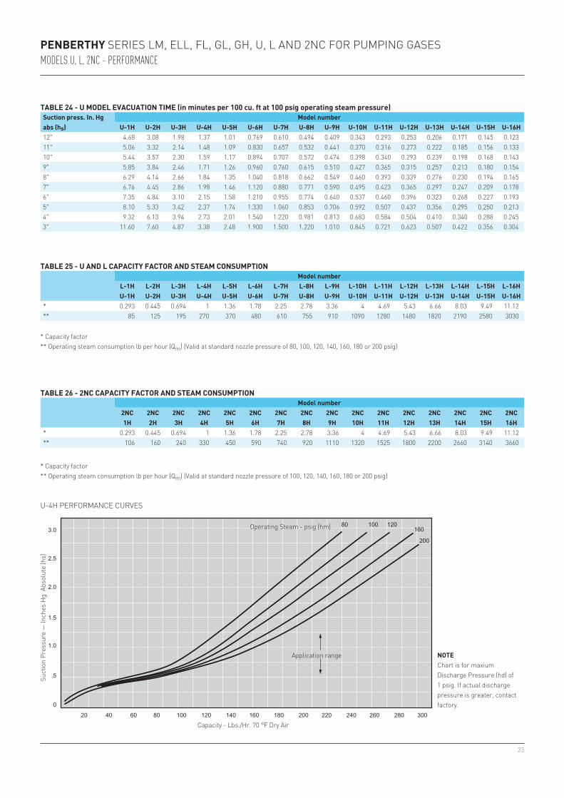
TABLE 24 - U MODEL EVACUATION TIME (in minutes per 100 cu. ft at 100 psig operating steam pressure)Suction press. In. Hg abs (hs)
Model numberU-1H U-2H U-3H U-4H U-5H U-6H U-7H U-8H U-9H U-10H U-11H U-12H U-13H U-14H U-15H U-16H
TABLE 25 - U AND L CAPACITY FACTOR AND STEAM CONSUMPTIONModel number
L-1H L-2H L-3H L-4H L-5H L-6H L-7H L-8H L-9H L-10H L-11H L-12H L-13H L-14H L-15H L-16HU-1H U-2H U-3H U-4H U-5H U-6H U-7H U-8H U-9H U-10H U-11H U-12H U-13H U-14H U-15H U-16H
* Capacity factor** Operating steam consumption lb per hour (Qm) (Valid at standard nozzle pressure of 80, 100, 120, 140, 160, 180 or 200 psig)
TABLE 26 - 2NC CAPACITY FACTOR AND STEAM CONSUMPTIONModel number
2NC 2NC 2NC 2NC 2NC 2NC 2NC 2NC 2NC 2NC 2NC 2NC 2NC 2NC 2NC 2NC1H 2H 3H 4H 5H 6H 7H 8H 9H 10H 11H 12H 13H 14H 15H 16H
* Capacity factor** Operating steam consumption lb per hour (Qm) (Valid at standard nozzle pressure of 100, 120, 140, 160, 180 or 200 psig)
U-4H PERFORMANCE CURVES
Suct
ion
Pres
sure
— In
ches
Hg
Abs
olut
e (h
s)
Capacity - Lbs./Hr. 70 °F Dry Air
NOTE Chart is for maxium Discharge Pressure (hd) of 1 psig. If actual discharge pressure is greater, contact factory.
Operating Steam - psig (hm)
Application range
24
12
9
6
3
0
10 20 30 40 50 60 70 80 90 100 110 120 130 140
80 100 120 160
200
3.0
2.5
2.0
1.5
1.0
.5
05 10 15 20 25 30 35 40 45
100 120 160 200
PENBERTHY SERIES LM, ELL, FL, GL, GH, U, L AND 2NC FOR PUMPING GASESMODELS U, L, 2NC - PERFORMANCE
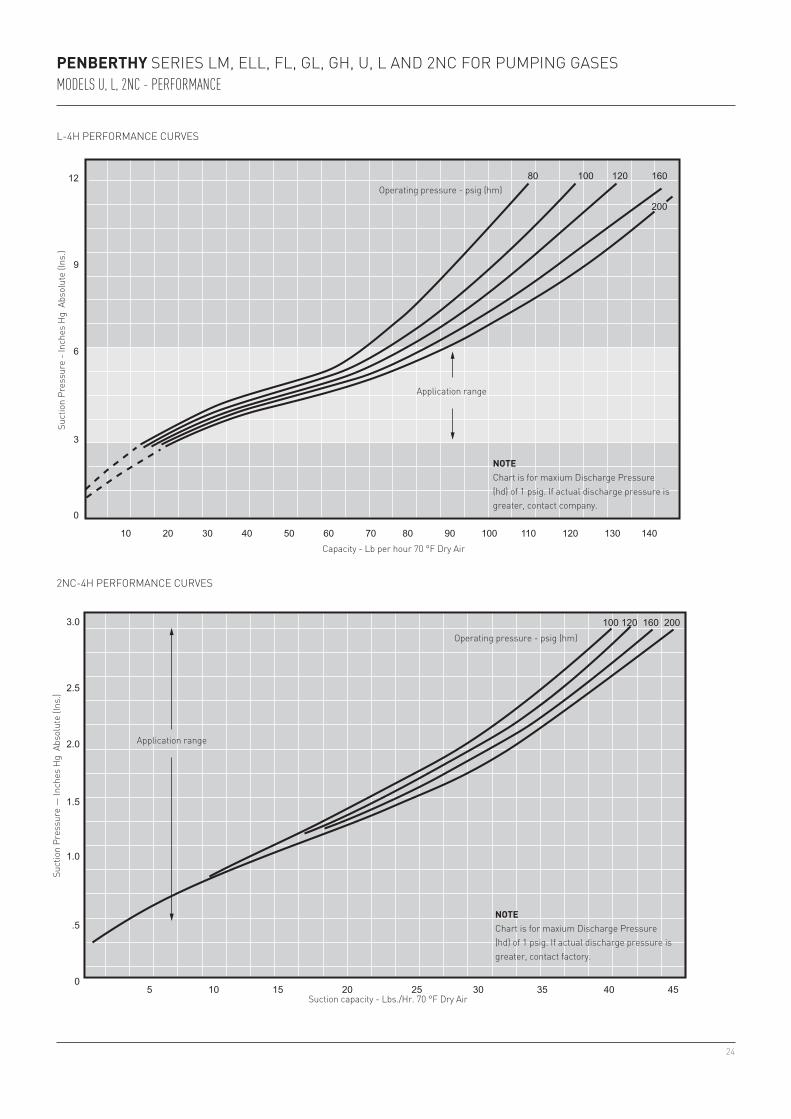
L-4H PERFORMANCE CURVES
2NC-4H PERFORMANCE CURVES
Suct
ion
Pres
sure
— In
ches
Hg
Abs
olut
e (In
s.)
Capacity - Lb per hour 70 °F Dry Air
NOTE Chart is for maxium Discharge Pressure (hd) of 1 psig. If actual discharge pressure is greater, contact factory.
Operating pressure - psig (hm)
Suct
ion
Pres
sure
- In
ches
Hg
Abs
olut
e (In
s.)
Suction capacity - Lbs./Hr. 70 °F Dry Air
NOTE Chart is for maxium Discharge Pressure (hd) of 1 psig. If actual discharge pressure is greater, contact company.
Operating pressure - psig (hm)
Application range
Application range
25
'A'
C'D'NPT
'E' 'F'
'B'
L-1H, U-1H 9¼ 2¼ 1¾ ½ 1 1L-2H, U-2H 10¾ 2¼ 1¾ ½ 1 1L-3H, U-3H 13½ 2¾ 2½ 1 1½ 1½L-4H, U-4H 15½ 2¾ 2½ 1 1½ 1½L-5H, U-5H 18⅛ 3⅛ 3 1¼ 2 2L-6H, U-6H 20⅛ 3⅛ 3 1¼ 2 2L-7H, U-7H 22¾ 3½ 4⅛ 1½ 2½ 2½L-8H, U-8H 24¾ 3½ 4⅛ 1½ 2½ 2½L-9H, U-9H 27½ 4 5 2 3 3L-10H, U-10H 29½ 4 5 2 3 3L-11H, U-11H 31½ 4 5 2 3 3L-12H, U-12H 33½ 4 5 2 3 3L-13H, U-13H 38⅛ 5 6 3 4 4L-14H, U-14H 41⅛ 5 6 3 4 4L-15H, U-15H 45 5⅞ 6 3 4 4L-16H, U-16H 47½ 5⅞ 6 3 4 4
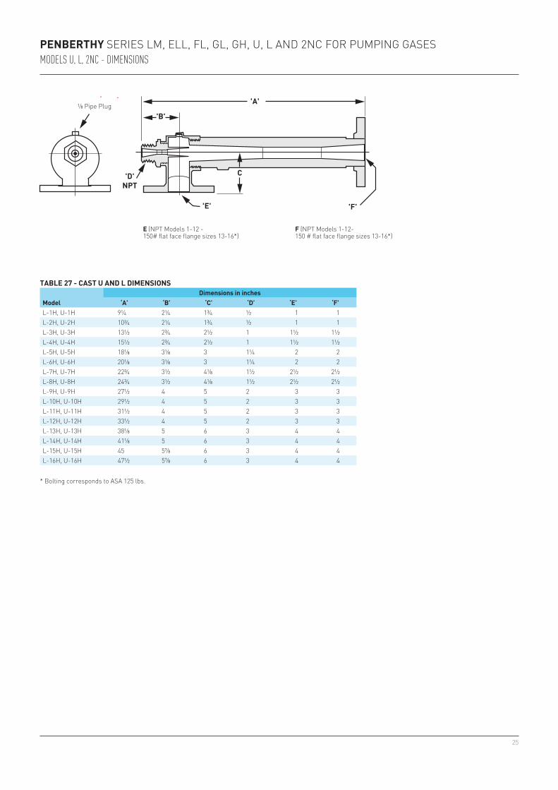
PENBERTHY SERIES LM, ELL, FL, GL, GH, U, L AND 2NC FOR PUMPING GASESMODELS U, L, 2NC - DIMENSIONS
TABLE 27 - CAST U AND L DIMENSIONS
Model Dimensions in inches
‘A’ ‘B’ ‘C’ ‘D’ ‘E’ ‘F’
E (NPT Models 1-12 -150# flat face flange sizes 13-16*)
F (NPT Models 1-12-150 # flat face flange sizes 13-16*)
⅛ Pipe Plug
* Bolting corresponds to ASA 125 lbs.
26
'A'
'G'
'D'NPT
'E'
'F'
'H'
'D'NPT
'B'
'C'
2NC1H 9¼ 2¼ 1¾ ½ 1 1 10⅛ 2¼2NC2H 10¾ 2¼ 1¾ ½ 1 1 11⅝ 2¼2NC3H 13½ 2¾ 2½ 1 1½ 1½ 15¼ 2¾2NC4H 15½ 2¾ 2½ 1 1½ 1½ 17¼ 2¾2NC5H 18⅛ 3⅛ 3 1¼ 2 2 19⅞ 3⅛2NC6H 20⅛ 3⅛ 3 1¼ 2 2 21⅞ 3⅛2NC7H 22¾ 3½ 4⅛ 1½ 2½ 2½ 25¼ 3½2NC8H 24¾ 3½ 4⅛ 1½ 2½ 2½ 27¼ 3½2NC9H 27½ 4 5 2 3 3 30¾ 42NC10H 29½ 4 5 2 3 3 32¾ 42NC11H 31½ 4 5 2 3 3 34¾ 42NC12H 33½ 4 5 2 3 3 36¾ 42NC13H 38⅛ 5 6 3 4 4 39⅛ 52NC14H 41⅛ 5 6 3 4 4 44⅛ 52NC15H 45 5 6 3 4 4 45⅛ 5⅞2NC16H 47½ 5 6 3 4 4 47⅝ 5⅞
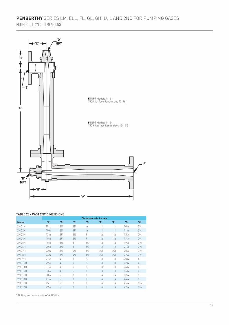
TABLE 28 - CAST 2NC DIMENSIONS
Model Dimensions in inches
‘A’ ‘B’ ‘C’ ‘D’ ‘E’ ‘F’ ‘G’ ‘H’
* Bolting corresponds to ASA 125 lbs.
PENBERTHY SERIES LM, ELL, FL, GL, GH, U, L AND 2NC FOR PUMPING GASESMODELS U, L, 2NC - DIMENSIONS
E (NPT Models 1-12 -150# flat face flange sizes 13-16*)
F (NPT Models 1-12-150 # flat face flange sizes 13-16*)
27
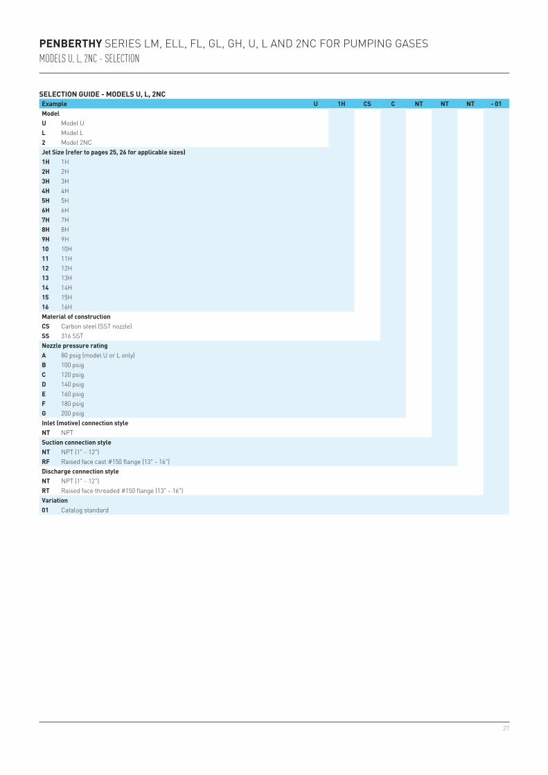
PENBERTHY SERIES LM, ELL, FL, GL, GH, U, L AND 2NC FOR PUMPING GASESMODELS U, L, 2NC - SELECTION
SELECTION GUIDE - MODELS U, L, 2NCExample U 1H CS C NT NT NT - 01ModelU Model UL Model L2 Model 2NCJet Size (refer to pages 25, 26 for applicable sizes)1H 1H2H 2H3H 3H4H 4H5H 5H6H 6H7H 7H8H 8H9H 9H10 10H11 11H12 12H13 13H14 14H15 15H16 16HMaterial of constructionCS Carbon steel (SST nozzle)SS 316 SSTNozzle pressure ratingA 80 psig (model U or L only)B 100 psigC 120 psigD 140 psigE 160 psigF 180 psigG 200 psigInlet (motive) connection styleNT NPTSuction connection styleNT NPT (1" - 12")RF Raised face cast #150 flange (13" - 16")Discharge connection styleNT NPT (1" - 12")RT Raised face threaded #150 flange (13" - 16")Variation01 Catalog standard
28
PENBERTHY SERIES LM, ELL, FL, GL, GH, U, L AND 2NC FOR PUMPING GASESMODELS GL, GH, U, L, 2NC
DRY AIR EQUIVALENT (DAE) CONVERSIONS FOR GL, GH, U, L AND 2NC MODELS
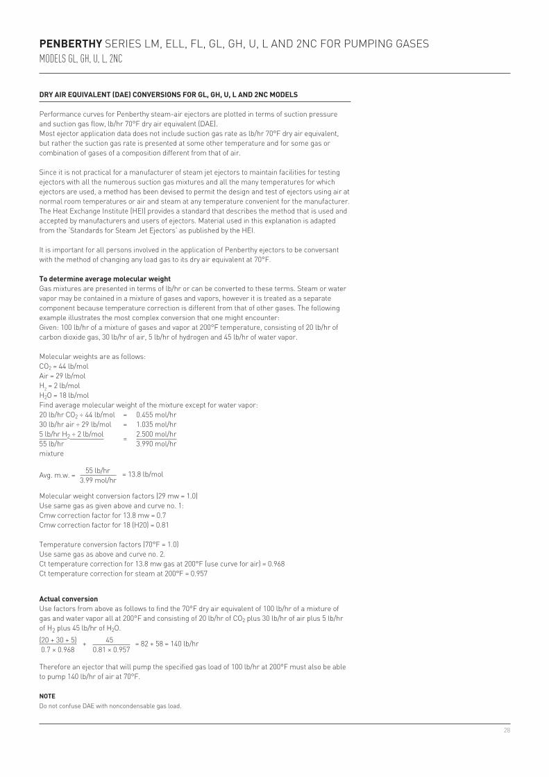
Performance curves for Penberthy steam-air ejectors are plotted in terms of suction pressure and suction gas flow, lb/hr 70°F dry air equivalent (DAE).Most ejector application data does not include suction gas rate as lb/hr 70°F dry air equivalent, but rather the suction gas rate is presented at some other temperature and for some gas or combination of gases of a composition different from that of air.
Since it is not practical for a manufacturer of steam jet ejectors to maintain facilities for testing ejectors with all the numerous suction gas mixtures and all the many temperatures for which ejectors are used, a method has been devised to permit the design and test of ejectors using air at normal room temperatures or air and steam at any temperature convenient for the manufacturer. The Heat Exchange Institute (HEI) provides a standard that describes the method that is used and accepted by manufacturers and users of ejectors. Material used in this explanation is adapted from the ‘Standards for Steam Jet Ejectors’ as published by the HEI.
It is important for all persons involved in the application of Penberthy ejectors to be conversant with the method of changing any load gas to its dry air equivalent at 70°F.
To determine average molecular weight Gas mixtures are presented in terms of lb/hr or can be converted to these terms. Steam or water vapor may be contained in a mixture of gases and vapors, however it is treated as a separate component because temperature correction is different from that of other gases. The following example illustrates the most complex conversion that one might encounter:Given: 100 lb/hr of a mixture of gases and vapor at 200°F temperature, consisting of 20 lb/hr of carbon dioxide gas, 30 lb/hr of air, 5 lb/hr of hydrogen and 45 lb/hr of water vapor.
Molecular weights are as follows:CO2 = 44 lb/molAir = 29 lb/molH2 = 2 lb/molH2O = 18 lb/molFind average molecular weight of the mixture except for water vapor: 20 lb/hr CO2 ÷ 44 lb/mol = 0.455 mol/hr30 lb/hr air ÷ 29 lb/mol = 1.035 mol/hr5 lb/hr H2 ÷ 2 lb/mol = 2.500 mol/hr55 lb/hr 3.990 mol/hrmixture
Avg. m.w. = 55 lb/hr = 13.8 lb/mol 3.99 mol/hr
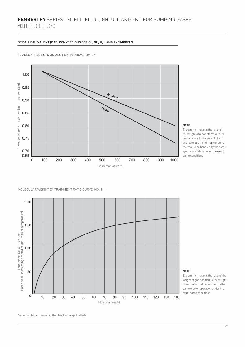
Molecular weight conversion factors (29 mw = 1.0)Use same gas as given above and curve no. 1:Cmw correction factor for 13.8 mw = 0.7Cmw correction factor for 18 (H20) = 0.81
Temperature conversion factors (70°F = 1.0) Use same gas as above and curve no. 2.Ct temperature correction for 13.8 mw gas at 200°F (use curve for air) = 0.968Ct temperature correction for steam at 200°F = 0.957
Actual conversion Use factors from above as follows to find the 70°F dry air equivalent of 100 lb/hr of a mixture of gas and water vapor all at 200°F and consisting of 20 lb/hr of CO2 plus 30 lb/hr of air plus 5 lb/hr of H2 plus 45 lb/hr of H2O.(20 + 30 + 5) + 45 = 82 + 58 = 140 lb/hr 0.7 × 0.968 0.81 × 0.957
Therefore an ejector that will pump the specified gas load of 100 lb/hr at 200°F must also be able to pump 140 lb/hr of air at 70°F.
NOTEDo not confuse DAE with noncondensable gas load.
29
2.00
1.50
1.00
.50
0 10 20 30 40 50 60 70 80 90 100 110 120 130 140
1.00
0.95
0.90
0.85
0.80
0.75
0.700.69
0 100 200 300 400 500 600 700 800 900 1000
PENBERTHY SERIES LM, ELL, FL, GL, GH, U, L AND 2NC FOR PUMPING GASESMODELS GL, GH, U, L, 2NC
DRY AIR EQUIVALENT (DAE) CONVERSIONS FOR GL, GH, U, L AND 2NC MODELS
*reprinted by permission of the Heat Exchange Institute.
MOLECULAR WEIGHT ENTRAINMENT RATIO CURVE (NO. 1)*
TEMPERATURE ENTRAINMENT RATIO CURVE (NO. 2)*
Air (Gas)
Entr
ainm
ent R
atio
— P
er C
ent
(Bas
ed o
n al
l gas
es b
eing
han
dled
at 7
0 °F
to 8
0 °F
tem
pera
ture
)
NOTE Entrainment ratio is the ratio of the weight of gas handled to the weight of air that would be handled by the same ejector operation under the exact same conditions
Molecular weight
Entr
ainm
ent R
atio
— P
er C
ent (
70 °
F - 1
00 P
er C
ent)
NOTE Entrainment ratio is the ratio of the weight of air or steam at 70 °F temperature to the weight of air or steam at a higher tepmerature that would be handled by the same ejector operation under the exact same conditions
Gas temperature, °F
Steam

30© 2017 Emerson. All rights reserved.