Embed Size (px)
Citation preview

Database DesignDatabase Design&&
MappingMapping
Database ApplicationDatabase ApplicationSAK 3408SAK 3408

Database System Design
User viewsof data.
Conceptualdata model.
Customer(CustomerID, Name, Address, …)
SalesPerson(EmployeeID, Name, Commission, … )
Order(OrderID, OrderDate, CustomerID, EmployeeID, … )
OrderItem(OrderID, ItemID, Quantity, Price, … )
Item(ItemID, Description, ListPrice, …)
Implementation(relational)data model.
Physicaldatastorage.
Class diagram that shows business entities, relationships, and rules.
List of nicely-behaved tables. Use data normalization to derive the list.
Indexes and storage methods to improve performance.

Goal: To produce an information system that adds value for the user
Reduce costsIncrease sales/revenueProvide competitive advantage
Objective: To understand the system
To improve itTo communicate with users and IT staff
Methodology: Build models of the system
The Need for Design

Designing Systems
Designs are a model of existing & proposed systems
They provide a picture or representation of realityThey are a simplificationSomeone should be able to read your design (model) and describe the features of the actual system.
You build models by talking with the usersIdentify processesIdentify objectsDetermine current problems and future needsCollect user documents (views)
Break complex systems into pieces and levels

Design StagesInitiation
ScopeFeasibility studyCost & Time estimates
Requirements AnalysisUser Views & Needs
FormsReports
Processes & EventsEntity & Attributes
Conceptual DesignModels
Data flow diagramEntity RelationshipsObjects
User feedback
Physical DesignTable definitionsApplication development
QueriesFormsReportsApplication integration
Data storageSecurityProcedures
ImplementationTrainingPurchasesData conversionInstallation
Evaluation & Review

Initial Steps of Design
1. Identify the exact goals of the system.
2.Talk with the users to identify the basic forms and reports.
3. Identify the data items to be stored.
4.Design the classes (tables) and relationships.
5. Identify any business constraints.
6.Verify the design matches the business rules.

Business RuleBR are important in data modelling because they govern how data are – handled and stored.Basic BR :
Data namesData definition
Names and definition must provide for :
Entity typesAttributRelationship

Guideline Data Names
Relate to business – customer \ File10Be meaningful – avoid is, it, hasBe unique – homeadd, campusaddRepeatable–studbirthdate, stafbirthdate

Data Definition “ A course is a module of instruction in a particular area.”“A customer may request a model car from a rental branch in a particular date.”Guideline :
A definition will state such characteristics of the data objects.Whether the data is singular or pluralWho determine the value for the dataWhether data is static or changes over timeWhether the data is optional or an emptyWhere, when and how data is created.

The E-R Model
E-R model – a logical representation of the data for an organization or for a business area
E-R diagram – a graphical representation of an entity-relationship model

E-R Model Constructs
EntityAttributeRelationship

Figure 2.4 Basic E-R Notation
Entity symbols
Relationship symbols
Attribute symbols
A special entity that is also a relationship

Figure 2.3 Sample E-R Diagram
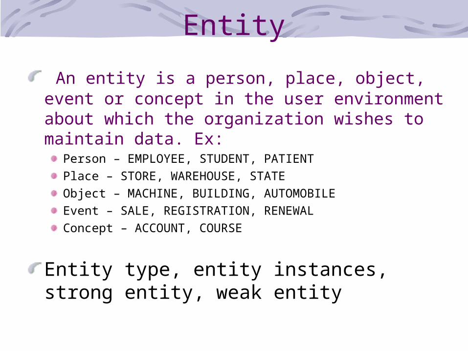
Entity
An entity is a person, place, object, event or concept in the user environment about which the organization wishes to maintain data. Ex:
Person – EMPLOYEE, STUDENT, PATIENTPlace – STORE, WAREHOUSE, STATEObject – MACHINE, BUILDING, AUTOMOBILEEvent – SALE, REGISTRATION, RENEWALConcept – ACCOUNT, COURSE
Entity type, entity instances, strong entity, weak entity

Entity Type vs. Entity Instance
Entity Type Share common characteristicGiven a name (CAPITAL LETTER)RectangleCollection of entities (often corresponds to a table). Ex: EMPLOYEE
Entity Instancesa single occurrence of an entity type (often corresponds to a row in a table) Ex: may be 100 of instances of entity EMPLOYEE stored in database.

Entity Type vs. Entity Instance (cont.)
Entity Type : EMPLOYEE
Attribut : EMP_NUM CHAR(10)NAME CHAR(25)STATE CHAR(35)
2 instances of EMPLOYEE :00123 02345Ali AmirPerak Kedah

Strong vs. Weak Entity Types
Strong Entity Type entity that exists independently of other entity typesUnique characteristicCalled an identifierEx: STUDENT, EMPLOYEE
Weak Entity Type entity type whose existence depends on some other entity typeNo meaning in ERD without strong entity.

Figure 2.10 Strong and weak entities
Strong entity Weak entityIdentifying relationship

Attribute
property or characteristic of an entity type (often corresponds to a field in a table)Ex:
entity type – STUDENTAttributes – name, add, id, program
Simple att vs composite att.Single-valued att vs multivalued attStored att vs derived attIdentifier att.

Simple vs. Composite Attribute
Simple attribute – cannot broken into smaller components
Composite attribute – can broken into component parts

Simple key attribute
The key is underlined

a) Composite attribute
An attribute broken into component parts

b) Composite key attribute
The key is composed of two subparts

Single-Valued vs. Multivalued Attribute
Single-Valued – each of the attributes has one value
Multivalued – attribute more than one value

Entity with a multivalued attribute (Skill)
Multivalued: an employee can have more than one skill

Stored vs. Derived Attributes
Stored attribute – data input or set
Derived Attribute – attribute whose values can be calculated from related attribute values.

Entity with a derived attribute (Years_Employed)
Derived from date employed and current date

Identifiers (Keys)
Identifier (Primary Key) - An attribute (or combination of attributes) that uniquely identifies individual instances of an entity typeComposite Identifier – an identifier that consists of a composite attribute. Candidate Key – an attribute that could be a key…satisfies the requirements for being a key

Characteristics of Identifiers
Will not change in valueWill not be nullNo intelligent identifiers (e.g. containing locations or people that might change)Substitute new, simple keys for long, composite keys

Ex: identifier
The key is composed of two subparts

Relationship
Relationship link between entities (corresponds to primary key-foreign key equivalencies in related tables)

Relationships (cont.)Relationship Types vs. Relationship Instances
The relationship type is modeled as the diamond and lines between entity types…the instance is between specific entity instances
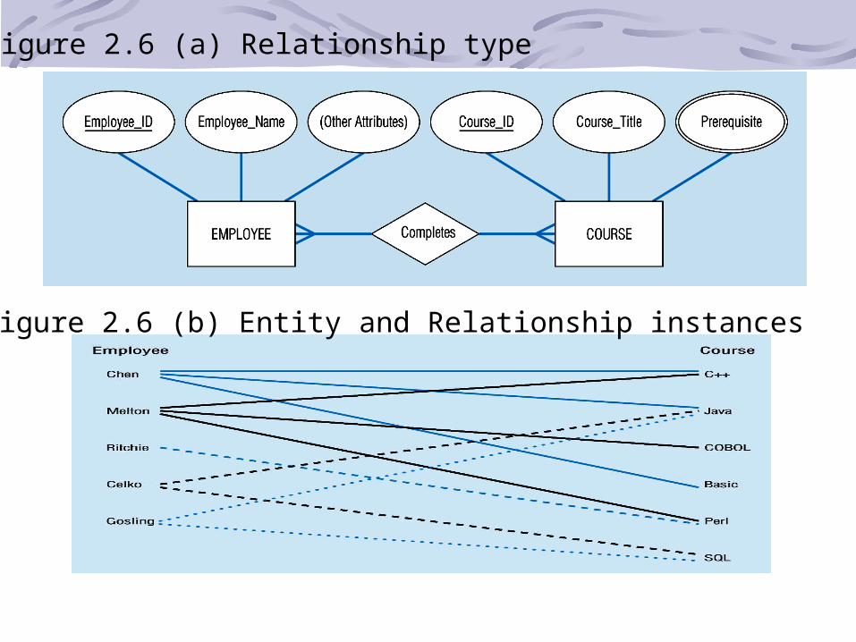
Figure 2.6 (a) Relationship type
Figure 2.6 (b) Entity and Relationship instances

Relationships (cont.)Relationships can have attributes
These describe features pertaining to the association between the entities in the relationship
Two entities can have more than one type of relationship between them (multiple relationships)Associative Entity = combination of relationship and entity

Degree of Relationships
Degree of a Relationship is the number of entity types that participate in it
Unary RelationshipBinary RelationshipTernary Relationship

Figure 2.7 Degree of relationships
One entity related to another of the same entity type
Entities of two different types related to each other
Entities of three different types related to each other

Cardinality of Relationships
One – to – OneEach entity in the relationship will have exactly one related entity
One – to – ManyAn entity on one side of the relationship can have many related entities, but an entity on the other side will have a maximum of one related entity
Many – to – ManyEntities on both sides of the relationship can have many related entities on the other side

Figure 2.8 Degree of relationships and Cardinality(a) Unary relationships

(b) Binary relationships

(c) Ternary relationships
Note: a relationship can have attributes of its own

Cardinality Constraints
Cardinality Constraints - the number of instances of one entity that can or must be associated with each instance of another entity. Minimum Cardinality
If zero, then optionalIf one or more, then mandatory
Maximum CardinalityThe maximum number

Figure 2.8 Cardinality Mandatory and Optional

(a) Basic relationship with only maximum cardinalities showing
(b) Mandatory minimum cardinalities
Figure 2.9 Cardinality Constraints

Employees and departments – entities can be related to one another in more than one way
Figure 2.10 Examples of multiple relationships

Strong vs. Weak Entities, andIdentifying Relationships
Strong entities exist independently of other types of entitieshas its own unique identifierrepresented with single-line rectangle
Weak entitydependent on a strong entity…cannot exist on its ownDoes not have a unique identifierrepresented with double-line rectangle
Identifying relationshiplinks strong entities to weak entitiesrepresented with double line diamond

Associative EntitiesIt’s an entity – it has attributes
AND it’s a relationship – it links entities together
When should a relationship with attributes instead be an associative entity?
All relationships for the associative entity should be manyThe associative entity could have meaning independent of the other entitiesThe associative entity preferably has a unique identifier, and should also have other attributesThe associative may be participating in other relationships other than the entities of the associated relationshipTernary relationships should be converted to associative entities

Figure 2.11 An associative entity
Associative entity involves a rectangle with a diamond inside.Note that the many-to-many cardinality symbols face toward the associative entity and not toward the other entities
(a) An associative entity (CERTIFICATE)

(b)Ternary relationship as an associative entity

RelationDefinition: A relation is a named, two-dimensional table of data
Table is made up of rows (records), and columns (attribute or field)
Not all tables qualify as relations
Requirements:Every relation has a unique name.Every attribute value is atomic (not multivalued, not composite)Every row is unique (can’t have two rows with exactly the same values for all their fields)Attributes (columns) in tables have unique namesThe order of the columns is irrelevantThe order of the rows is irrelevant

Correspondence with ER Model
Relations (tables) correspond with entity types and with many-to-many relationship typesRows correspond with entity instances and with many-to-many relationship instancesColumns correspond with attributes

KeyKeys are special fields that serve two main purposes:
Primary keys are unique identifiers of the relation. Examples include employee numbers, social security numbers, etc. This is how we can guarantee that all rows are uniqueForeign keys are identifiers that enable a dependent relation (on the many side of a relationship) to refer to its parent relation (on the one side of the relationship)
Keys can be simple (a single field) or composite (more than one field)Keys usually are used as indexes to speed up the response to user queries

Primary Key
Foreign Key (implements 1:N relationship between customer and order)
Combined, these are a composite primary key (uniquely identifies the order line)…individually they are foreign keys (implement M:N relationship between order and product)

Transforming E-R into Relations
Step 1: Mapping Regular Entities to Relations
1. Simple attributes: E-R attributes map directly onto the relation
2. Composite attributes: Use only their simple, component attributes
3. Multi-valued Attribute - Becomes a separate relation with a foreign key taken from the superior entity

(a) CUSTOMER entity type with simple attributes
Figure 2.12 Mapping a regular entity
(b) CUSTOMER relation

(a) CUSTOMER entity type with composite attribute
Figure 2.13 Mapping a composite attribute
(b) CUSTOMER relation with address detail

Figure 2.14 Mapping a multivalued attribute
1 – to – many relationship between original entity and new relation
(a)
Multivalued attribute becomes a separate relation with foreign key
(b)

Step 2: Mapping Weak EntitiesBecomes a separate relation with a foreign key taken from the superior entityPrimary key composed of:
Partial identifier of weak entityPrimary key of identifying relation (strong entity)
Transforming E-R into Relations

Figure 2.15 Mapping a weak entity
(a) Weak entity DEPENDENT

(b) Relations resulting from weak entity
NOTE: the domain constraint for the foreign key should NOT allow null value if DEPENDENT is a weak entity
Foreign key
Composite primary key

Step 3: Mapping Binary Relationships
One-to-Many - Primary key on the one side becomes a foreign key on the many sideMany-to-Many - Create a new new relationrelation with the primary keys of the two entities as its primary keyOne-to-One - Primary key on the mandatory side becomes a foreign key on the optional side
Transforming E-R into Relations

Figure 2.16 mapping a 1:M relationship
(a) Relationship between customers and orders

(b) Mapping the relationship
Foreign key
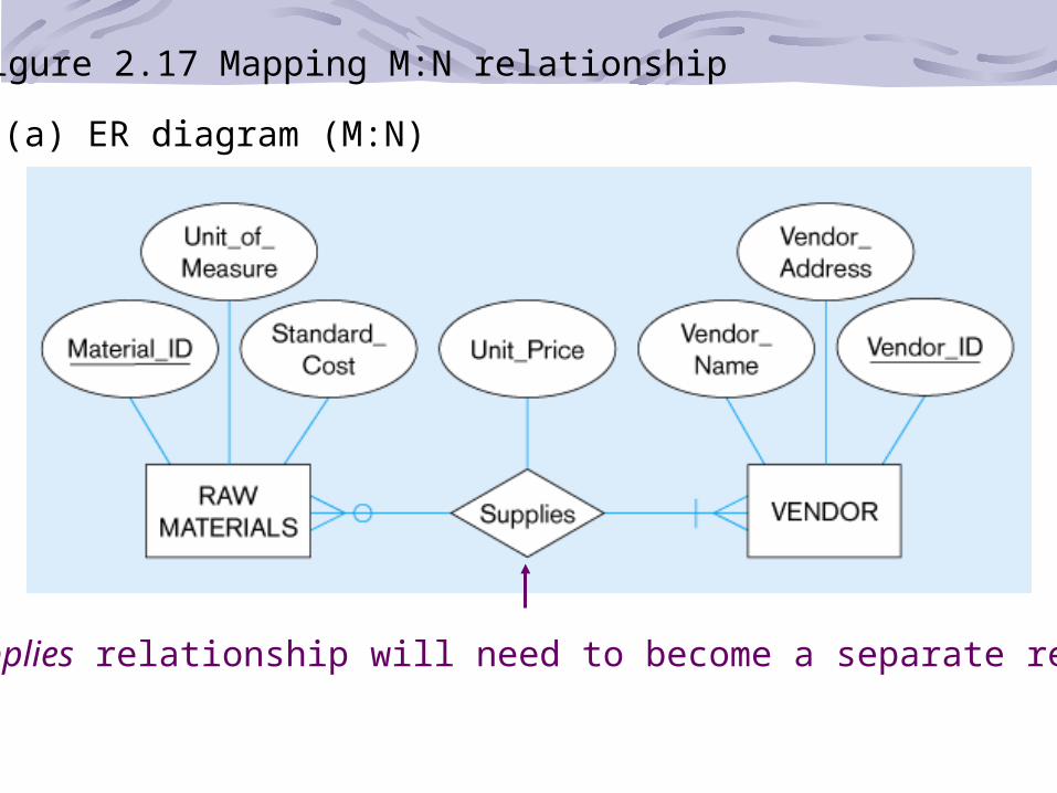
Figure 2.17 Mapping M:N relationship
(a) ER diagram (M:N)
The Supplies relationship will need to become a separate relation

(b) Three resulting relations
New intersection
relationForeign key
Foreign key
Composite primary key

Figure 2.18 Mapping a binary 1:1 relationship
(a) Binary 1:1 relationship

(b) Resulting relations

Step 4: Mapping Associative EntitiesIdentifier Not Assigned
Default primary key for the association relation is composed of the primary keys of the two entities (as in M:N relationship)
Identifier Assigned It is natural and familiar to end-usersDefault identifier may not be unique
Transforming E-R into Relations

Figure 2.19 Mapping an associative entity
(a) Associative entity

(b) Three resulting relations

Step 5: Mapping Unary Relationships
One-to-Many - Recursive foreign key in the same relationMany-to-Many - Two relations:
One for the entity typeOne for an associative relation in which the primary key has two attributes, both taken from the primary key of the entity
Transforming E-R into Relations

Figure 2.20 Mapping a unary 1:N relationship
(a) EMPLOYEE entity with Manages relationship
(b) EMPLOYEE relation with recursive foreign key

Mapping a unary M:N relationship
(a) Bill-of-materials relationships (M:N)
(b) ITEM and COMPONENT relations

Step 6: Mapping Ternary (and n-ary) Relationships
One relation for each entity and one for the associative entityAssociative entity has foreign keys to each entity in the relationship
Transforming E-R into Relations

Figure 2.21 Mapping a ternary relationship
(a) Ternary relationship with associative entity

(b) Mapping the ternary relationship
Remember that the primary key MUST be
unique