Embed Size (px)
Citation preview
DataComm V.34 PL Modem
Installation and Operation
060R115-000 Issue 1

060R115-000Issue 1
DataComm V.34 PL Modem
Installation and Operation
. No y , Inc. sumes
ited
panies
.
c.)
Copyright©2000 General DataComm, Inc. ALL RIGHTS RESERVED.
This publication and the software it describes contain proprietary and confidential informationpart of this document may be copied, photocopied, reproduced, translated or reduced to anelectronic or machine-readable format without prior written permission of General DataCommThe information in this document is subject to change without notice. General DataComm asno responsibility for any damages arising from the use of this document, including but not limto, lost revenue, lost data, claims by third parties, or other damages.
If you have comments or suggestions concerning this manual, please contact:
Technical Publications DepartmentGeneral DataComm, Inc.Park Road ExtensionMiddlebury, Connecticut USA 06762-1299
Telephone: 1 203 758 1811
TrademarksAll brand or product names are trademarks or registered trademarks of their respective comor organizations.
Documentation
Related Publications
A listing of related user manuals is provided below. In addition to the hardware and softwaremanuals, always read the software System Release Notes supplied with your GDC product
* For publications numbers, REV is the hardware manual revision (for example, -000, -001, etVREF (if listed) is the software revision (for example, -V120 would read, Version 1.2) and corresponds to the most current revision.
Revision History
Issue Number Date Description of Change
1 June 2000 First Issue
Table P-1 Related GDC Documents
Applicable Documents
Publication Name Publication Number*
Instruction Manual Universal System Shelf AC and DC-to-DC Models
010R313-REV
DataComm Shelf, Model DS-1 010R310-REV
DataComm Shelf, Model DS-5 010R340-REV
DataComm Shelf, Model DS-6 010R341-REV
ii V.34 PL Modem 060R115-000Installation and Operation Issue 1
Preface
ScopeThis manual describes how to install and operate the DataComm V.34 PL (Private Line) modem. The information contained in this manual has been carefully checked and is believed to be entirely reliable. However, as General DataComm improves the reliability, function, and design of their products, is possible that information may not be current. Contact General DataComm if you require updated information for this or any other General DataComm product.
General DataComm, Inc.Park Road ExtensionMiddlebury, Connecticut, USA 06762-1299Tel: 1 203 758 1811 Toll Free: 1 800 794 8246
Manual OrganizationThe online (web-based) manual uses active areas which allow you to navigate through portions of the manual by clicking on any blue text.
This manual is divided into the following chapters and appendices:
Chapter 1, Introduction
Chapter 2, Installation
Chapter 3, Operation
Chapter 4, Tests
Appendix A, Technical Specifications
Appendix B, Business Equipment Interface (TIA/EIA-232-F, ITU-T V.24/V.28/ISO 2110)
060R115-000 DataComm V.34 PL Modem iiiIssue 1 Instal latio n and Opera tion
Preface Safety Summary
re tor.
ute.
n
ult
n
g
Safety SummaryThe CAUTION, WARNING, and DANGER statements that appear throughout this manual aintended to provide critical information for the safety of both the service engineer and operaThese statements also enhance equipment reliability.
The definitions and symbols for CAUTION, WARNING, and DANGER comply with ANSI Z535.2, American National Standard for Environmental and Facility Safety Signs, and ANSIZ535.4, Product Safety Signs and Labels, issued by the American National Standards Instit
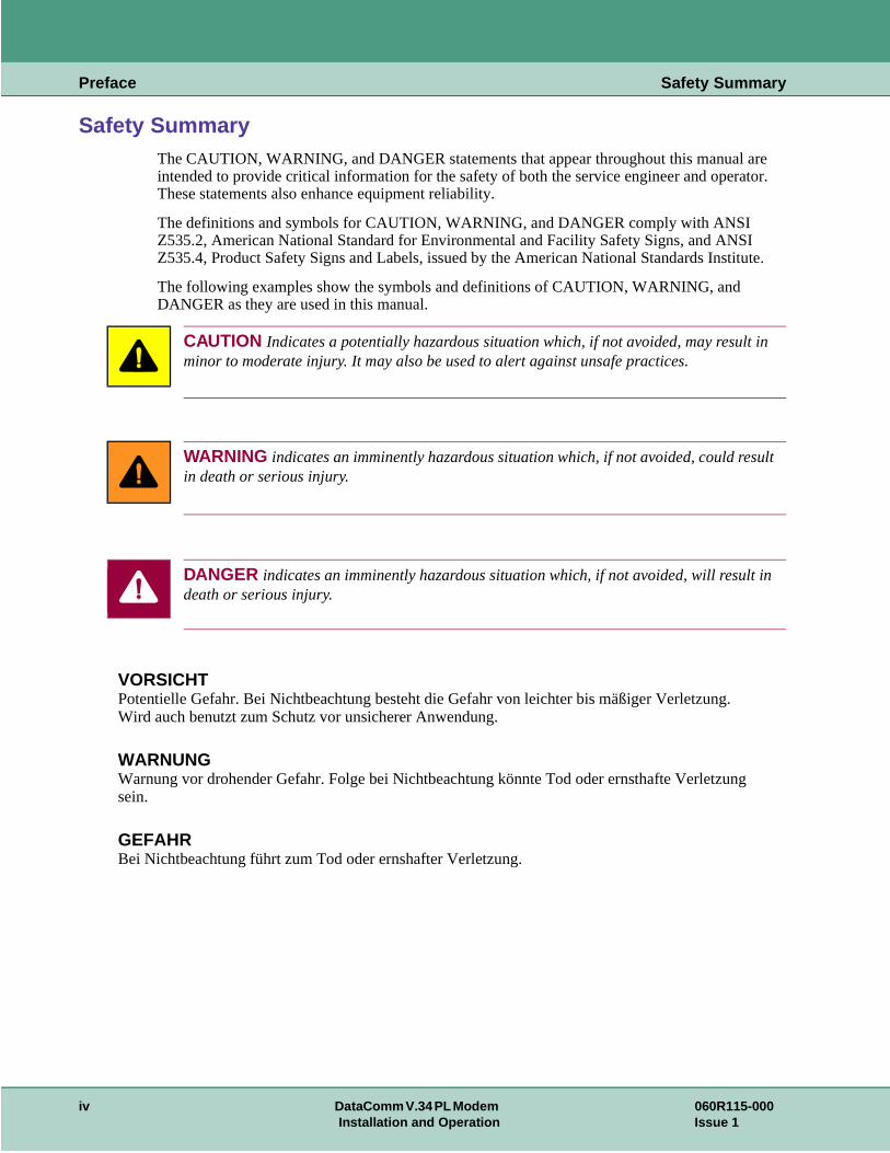
The following examples show the symbols and definitions of CAUTION, WARNING, and DANGER as they are used in this manual.
CAUTION Indicates a potentially hazardous situation which, if not avoided, may result iminor to moderate injury. It may also be used to alert against unsafe practices.
WARNING indicates an imminently hazardous situation which, if not avoided, could resin death or serious injury.
DANGER indicates an imminently hazardous situation which, if not avoided, will result ideath or serious injury.
VORSICHTPotentielle Gefahr. Bei Nichtbeachtung besteht die Gefahr von leichter bis mäßiger Verletzung.Wird auch benutzt zum Schutz vor unsicherer Anwendung.
WARNUNGWarnung vor drohender Gefahr. Folge bei Nichtbeachtung könnte Tod oder ernsthafte Verletzunsein.
GEFAHRBei Nichtbeachtung führt zum Tod oder ernshafter Verletzung.
iv DataComm V.34 PL Modem 060R115-000Installation and Operation Issue 1
Preface Safety Summary
ous
d.
tion.
puter atic s that
ential during
ipment on .
Safety GuidelinesAlways use the following guidelines when unsafe conditions exist or when potentially hazardvoltages are present:
• Always use caution and common sense.
• Repairs must be performed by qualified service personnel only.
• To reduce the risk of electrical shock, do not operate equipment with the cover remove
• Never install telephone jacks in a wet location unless the jack is designed for that loca
• Never touch uninsulated telephone wires or terminals unless the telephone line is disconnected at the network interface.
• Never install telephone wiring during an electrical storm.
Antistatic PrecautionsElectrostatic discharge (ESD) results from the buildup of static electricity and can cause comcomponents to fail. Electrostatic discharge occurs when a person whose body contains a stbuildup touches a computer component. The Innovx 553 may contain static-sensitive deviceare easily damaged. Proper handling, grounding and precautionary ESD measures are esswhen installing parts or cards. Keep parts and cards in antistatic packaging when not in use ortransport. If possible, use antistatic floorpads and workbench pads.
When handling components, always use an antistatic wrist strap connected to a grounded equframe or chassis. If a wrist strap is not available, periodically touch an unpainted metal surfacethe equipment. Never use a conductive tool, like a screwdriver or a paper clip, to set switches
060R115-000 DataComm V.34 PL Modem vIssue 1 Installation and Operation
Preface Service Support and Training
ice
d nters
ct
Service Support and TrainingVITAL Network Services, a General DataComm company, is committed to providing the servsupport and training needed to install, manage, and maintain your GDC equipment. VITAL Network Services provides hands-on training courses through VITAL Network Services Global Technology Training Services. Courses range from basic data communications, modems anmultiplexers, to complex network and ATM systems. Training courses are available at our cein the US, UK, France, Singapore and Mexico, as well as at a customer’s site.
For more information on VITAL Network Services or for technical support assistance, contaVITAL Network Services at:
VITAL Network Services World Headquarters6 Rubber Avenue Telephones: Faxes:Naugatuck, Connecticut 06770 USA 1 800 243 1030 1 203 723 5012
1 888 248 4825 1 203 729 7611http//www.vitalnetsvc.com 1 203 729 2461
VITAL Network Services Regional Sales and Service Offices:
North American Region Office6 Rubber AvenueNaugatuck, Connecticut 06770 USATelephones: 1 800 243 1030
1 888 248 48251 203 729 24611 800 361 2552 (French Canadian)
Training: 1 203 729 2461Faxes: 1 203 723 5012
1 203 729 7611
Central America, Latin AmericaVITAL Network ServicesPeriferico Sur 4225, Desp. 306C.P. 14210, Mexico D.F., Mexico
Telephone: 52 5 645 2238Training: 52 5 645 2238Fax: 52 5 645 5976
Europe, Middle East, AfricaVITAL Network ServicesMolly Millars CloseMolly Millars LaneWokingham, Berkshire RG41 2QF UK
Telephone: 44 1189 657200Training: 44 1189 657240Fax: 44 1189 657279
Asia PacificVITAL Network Services501 Orchard Road 05-05Wheelock Place, Singapore 238880
Telephone: 65 735 2123Training: 65 735 2123Fax: 65 735 6889
vi DataComm V.34 PL Modem 060R115-000Installation and Operation Issue 1
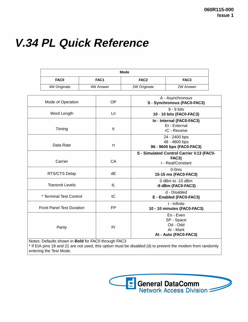
V.34 PL Quick Reference
060R115-000Issue 1
Mode
FAC0 FAC1 FAC2 FAC3
4W Originate 4W Answer 2W Originate 2W Answer
Mode of Operation OPA - Asynchronous
S - Synchronous (FAC0-FAC3)
Word Length Ln9 - 9 bits
10 - 10 bits (FAC0-FAC3)
Timing tI
In - Internal (FAC0-FAC3)Et - ExternalrC - Receive
Data Rate rt
24 - 2400 bps48 - 4800 bps
96 - 9600 bps (FAC0-FAC3)
Carrier CA
S - Simulated Control Carrier V.13 (FAC0-FAC3)
r - Real/Constant
RTS/CTS Delay dE0-0ms
15-15 ms (FAC0-FAC3)
Transmit Levels tL0 dBm to -15 dBm
-9 dBm (FAC0-FAC3)
* Terminal Test Control tCd - Disabled
E - Enabled (FAC0-FAC3)
Front Panel Test Duration FPI - Infinite
10 - 10 minutes (FAC0-FAC3)
Parity Pr
En - EvenSP - SpaceOd - OddAr - Mark
At - Auto (FAC0-FAC3)
Notes: Defaults shown in Bold for FAC0 through FAC3* If EIA pins 18 and 21 are not used, this option must be disabled (d) to prevent the modem from randomly entering the Test Mode.

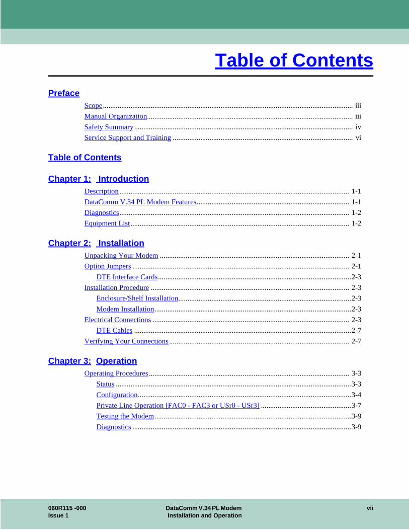
Table of Contents
ii
iv
-2
-1
3
3
3
3
-7
3
4
9
-9
PrefaceScope........................................................................................................................................ iii
Manual Organization................................................................................................................ i
Safety Summary.......................................................................................................................
Service Support and Training.................................................................................................. vi
Table of Contents
Chapter 1: IntroductionDescription............................................................................................................................. 1-1
DataComm V.34 PL Modem Features................................................................................... 1-1
Diagnostics............................................................................................................................. 1-2
Equipment List....................................................................................................................... 1
Chapter 2: InstallationUnpacking Your Modem....................................................................................................... 2-1
Option Jumpers...................................................................................................................... 2
DTE Interface Cards.........................................................................................................2-
Installation Procedure............................................................................................................ 2-
Enclosure/Shelf Installation..............................................................................................2-3
Modem Installation...........................................................................................................2-
Electrical Connections........................................................................................................... 2-
DTE Cables......................................................................................................................2
Verifying Your Connections.................................................................................................. 2-7
Chapter 3: OperationOperating Procedures............................................................................................................. 3-
Status................................................................................................................................3-3
Configuration....................................................................................................................3-
Private Line Operation [FAC0 - FAC3 or USr0 - USr3].................................................3-7
Testing the Modem...........................................................................................................3-
Diagnostics.......................................................................................................................3
060R115 -000 DataComm V.34 PL Modem viiIssue 1 Installation and Operation

Table of Contents
4
9
Chapter 4: TestsAnalog Loopback (ANALOOP)............................................................................................ 4-2
Analog Loopback with Self-Test........................................................................................... 4-3
Digital Loopback................................................................................................................... 4-
Remote Digital Loopback...................................................................................................... 4-5
Remote Digital Loopback with Self-Test.............................................................................. 4-7
End-to-End Self-Test............................................................................................................. 4-
viii DataComm V.34 PL Modem 060R115-000Installation and Operation Issue 1
m, and
s r 2-wire
200
Chapter 1: Introduction
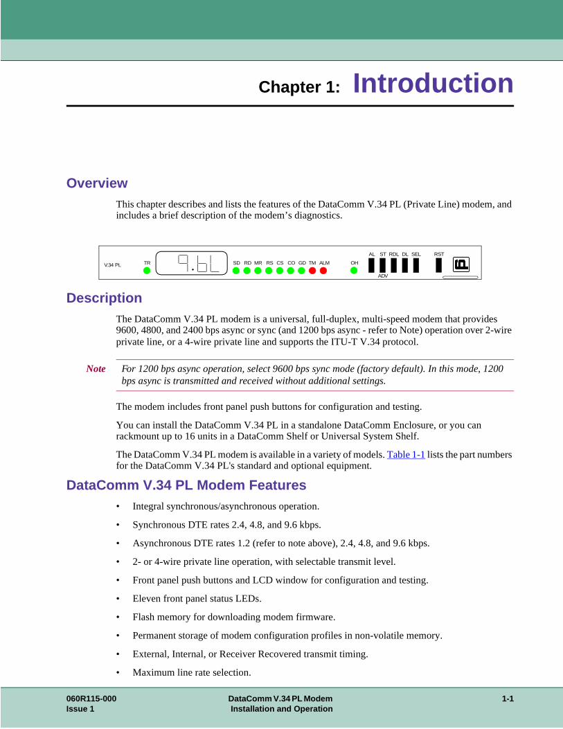
OverviewThis chapter describes and lists the features of the DataComm V.34 PL (Private Line) modeincludes a brief description of the modem’s diagnostics.
DescriptionThe DataComm V.34 PL modem is a universal, full-duplex, multi-speed modem that provide9600, 4800, and 2400 bps async or sync (and 1200 bps async - refer to Note) operation oveprivate line, or a 4-wire private line and supports the ITU-T V.34 protocol.
The modem includes front panel push buttons for configuration and testing.
You can install the DataComm V.34 PL in a standalone DataComm Enclosure, or you can rackmount up to 16 units in a DataComm Shelf or Universal System Shelf.
The DataComm V.34 PL modem is available in a variety of models. Table 1-1 lists the part numbers for the DataComm V.34 PL's standard and optional equipment.
DataComm V.34 PL Modem Features• Integral synchronous/asynchronous operation.
• Synchronous DTE rates 2.4, 4.8, and 9.6 kbps.
• Asynchronous DTE rates 1.2 (refer to note above), 2.4, 4.8, and 9.6 kbps.
• 2- or 4-wire private line operation, with selectable transmit level.
• Front panel push buttons and LCD window for configuration and testing.
• Eleven front panel status LEDs.
• Flash memory for downloading modem firmware.
• Permanent storage of modem configuration profiles in non-volatile memory.
• External, Internal, or Receiver Recovered transmit timing.
• Maximum line rate selection.
Note For 1200 bps async operation, select 9600 bps sync mode (factory default). In this mode, 1bps async is transmitted and received without additional settings.
V.34 PL TR SD RD MR RS CS CO GD TM ALM OH
AL ST RDL DL SEL RST
ADV
060R115-000 DataComm V.34 PL Modem 1-1Issue 1 Installation and Operation
Introduction Diagnostics
an Loop d h the
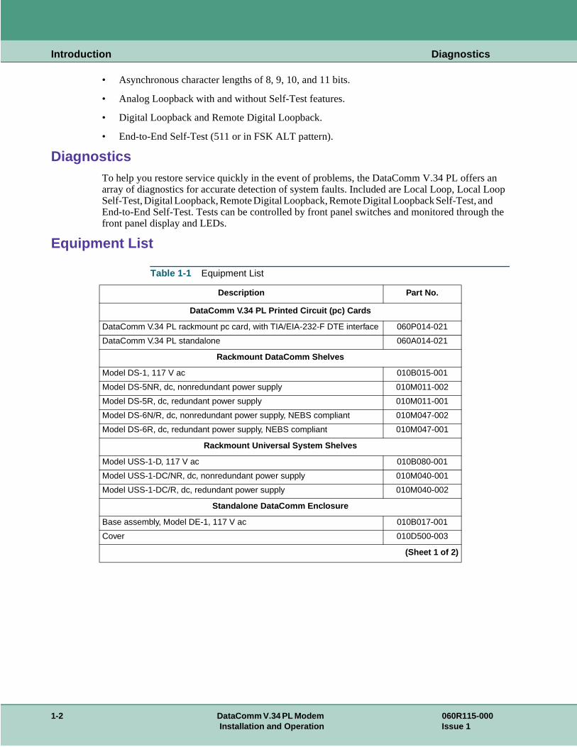
• Asynchronous character lengths of 8, 9, 10, and 11 bits.
• Analog Loopback with and without Self-Test features.
• Digital Loopback and Remote Digital Loopback.
• End-to-End Self-Test (511 or in FSK ALT pattern).
DiagnosticsTo help you restore service quickly in the event of problems, the DataComm V.34 PL offersarray of diagnostics for accurate detection of system faults. Included are Local Loop, Local Self-Test, Digital Loopback, Remote Digital Loopback, Remote Digital Loopback Self-Test, anEnd-to-End Self-Test. Tests can be controlled by front panel switches and monitored througfront panel display and LEDs.
Equipment List
Table 1-1 Equipment List
Description Part No.
DataComm V.34 PL Printed Circuit (pc) Cards
DataComm V.34 PL rackmount pc card, with TIA/EIA-232-F DTE interface 060P014-021
DataComm V.34 PL standalone 060A014-021
Rackmount DataComm Shelves
Model DS-1, 117 V ac 010B015-001
Model DS-5NR, dc, nonredundant power supply 010M011-002
Model DS-5R, dc, redundant power supply 010M011-001
Model DS-6N/R, dc, nonredundant power supply, NEBS compliant 010M047-002
Model DS-6R, dc, redundant power supply, NEBS compliant 010M047-001
Rackmount Universal System Shelves
Model USS-1-D, 117 V ac 010B080-001
Model USS-1-DC/NR, dc, nonredundant power supply 010M040-001
Model USS-1-DC/R, dc, redundant power supply 010M040-002
Standalone DataComm Enclosure
Base assembly, Model DE-1, 117 V ac 010B017-001
Cover 010D500-003
(Sheet 1 of 2)
1-2 DataComm V.34 PL Modem 060R115-000Installation and Operation Issue 1
Introduction Equipment List
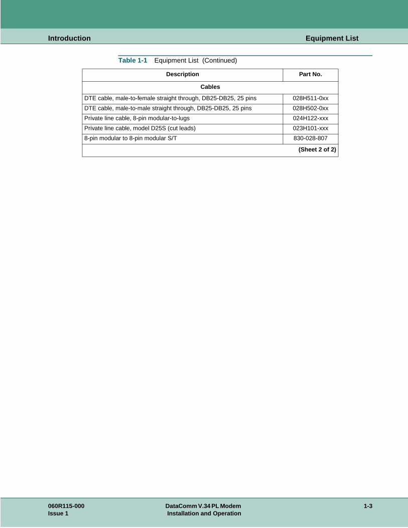
Cables
DTE cable, male-to-female straight through, DB25-DB25, 25 pins 028H511-0xx
DTE cable, male-to-male straight through, DB25-DB25, 25 pins 028H502-0xx
Private line cable, 8-pin modular-to-lugs 024H122-xxx
Private line cable, model D25S (cut leads) 023H101-xxx
8-pin modular to 8-pin modular S/T 830-028-807
Table 1-1 Equipment List (Continued)
Description Part No.
(Sheet 2 of 2)
060R115-000 DataComm V.34 PL Modem 1-3Issue 1 Installation and Operation
Introduction Equipment List
1-4 DataComm V.34 PL Modem 060R115-000Installation and Operation Issue 1
en you
wn in
Chapter 2: Installation
OverviewThis section describes installation of the DataComm V.34 PL modem.
Unpacking Your ModemThe unit is shipped enclosed in a box and protected by packing material. Inspect the unit whreceive it. Notify the shipper of any damage immediately.
Keep the box and packing material to use if you ever need to reship the unit.
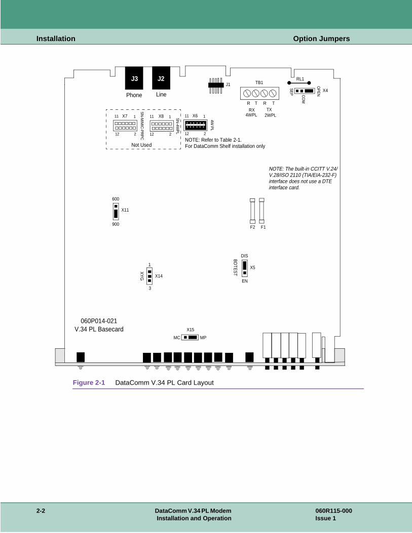
Option JumpersThe DataComm V.34 PL has four factory-set option jumpers. Verify that they are set as shoFigure 2-1 and described in Table 2-1.
060R115-000 DataComm V.34 PL Modem 2-1Issue 1 Installation and Operation
Installation Option Jumpers
Figure 2-1 DataComm V.34 PL Card Layout
060P014-021
J3 J2
Phone Line
J1
R T R T
RX4WPL
TX2WPL
RL1TB1 O
PE
N
SE
P X4
CO
M
X7 1
212
11 X6 1
212
11
SN
-MIM
IC-P
RP
C
4W P
L
SN
-4WP
L
X8 1
212
11
NOTE: Refer to Table 2-1.
X11
600
900
X5
DIS
ENX14
1
3
XY
G
V.34 PL Basecard
F1F2
NOTE: The built-in CCITT V.24/V.28/ISO 2110 (TIA/EIA-232-F)interface does not use a DTEinterface card.
MPMC
X15
BD
TES
T
Not Used For DataComm Shelf installation only
2-2 DataComm V.34 PL Modem 060R115-000Installation and Operation Issue 1
Installation Installation Procedure
he unit tall the s).
a
ll the
til it
ear
is
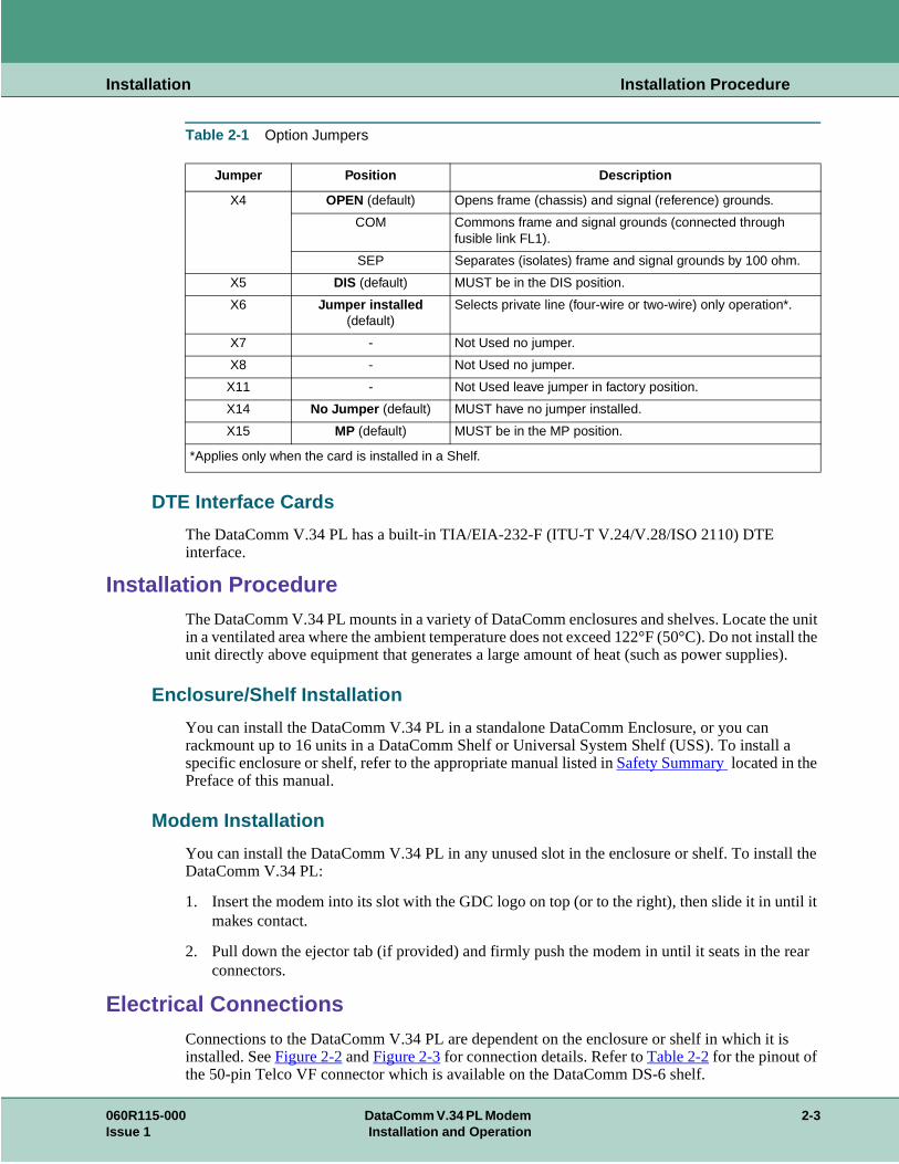
Table 2-1 Option Jumpers
DTE Interface Cards
The DataComm V.34 PL has a built-in TIA/EIA-232-F (ITU-T V.24/V.28/ISO 2110) DTE interface.
Installation ProcedureThe DataComm V.34 PL mounts in a variety of DataComm enclosures and shelves. Locate tin a ventilated area where the ambient temperature does not exceed 122°F (50°C). Do not insunit directly above equipment that generates a large amount of heat (such as power supplie
Enclosure/Shelf Installation
You can install the DataComm V.34 PL in a standalone DataComm Enclosure, or you can rackmount up to 16 units in a DataComm Shelf or Universal System Shelf (USS). To install specific enclosure or shelf, refer to the appropriate manual listed in Safety Summary located in the Preface of this manual.
Modem Installation
You can install the DataComm V.34 PL in any unused slot in the enclosure or shelf. To instaDataComm V.34 PL:
1. Insert the modem into its slot with the GDC logo on top (or to the right), then slide it in unmakes contact.
2. Pull down the ejector tab (if provided) and firmly push the modem in until it seats in the rconnectors.
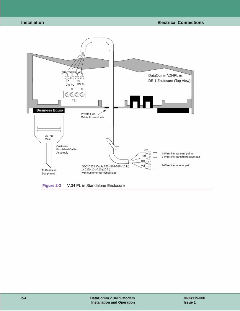
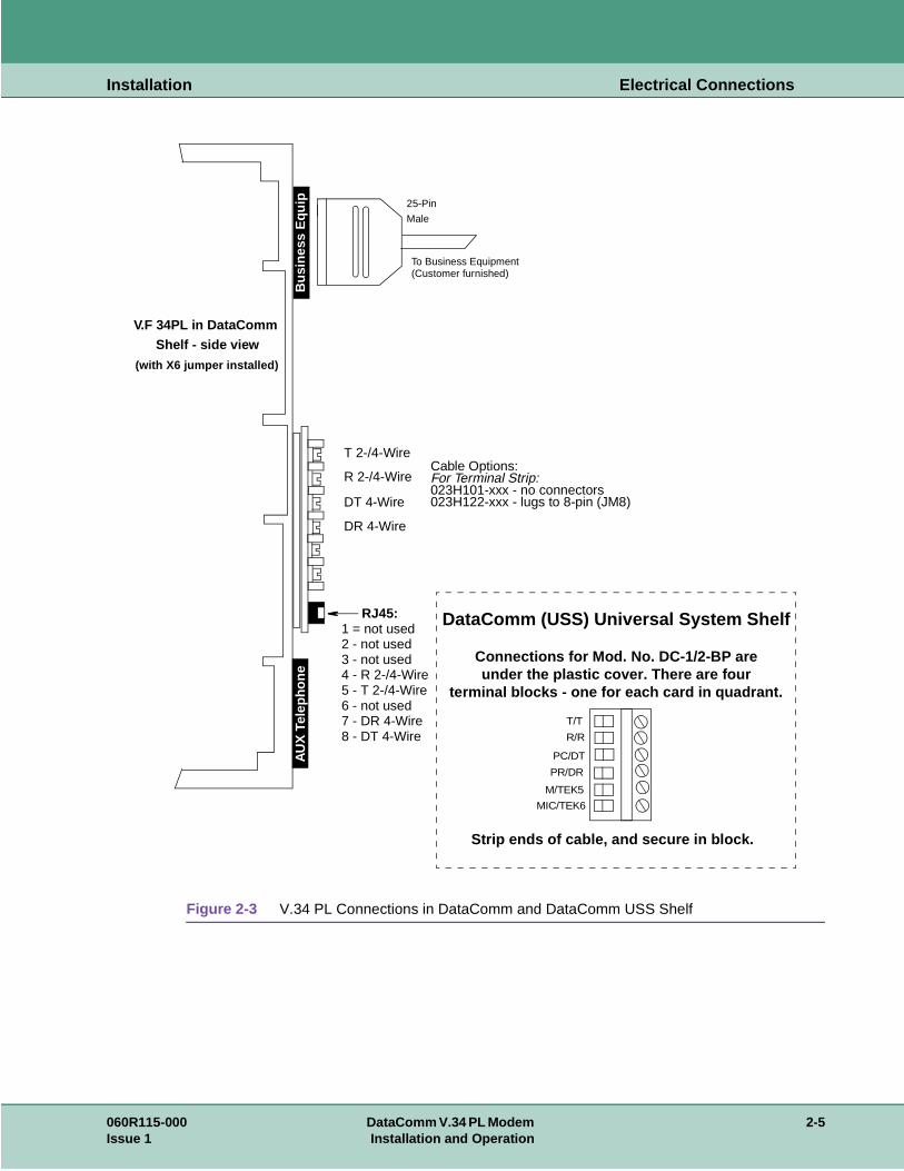
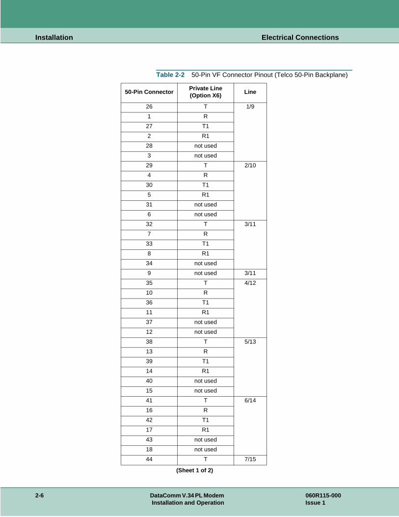
Electrical ConnectionsConnections to the DataComm V.34 PL are dependent on the enclosure or shelf in which it installed. See Figure 2-2 and Figure 2-3 for connection details. Refer to Table 2-2 for the pinout of the 50-pin Telco VF connector which is available on the DataComm DS-6 shelf.
Jumper Position Description
X4 OPEN (default) Opens frame (chassis) and signal (reference) grounds.
COM Commons frame and signal grounds (connected through fusible link FL1).
SEP Separates (isolates) frame and signal grounds by 100 ohm.
X5 DIS (default) MUST be in the DIS position.
X6 Jumper installed (default)
Selects private line (four-wire or two-wire) only operation*.
X7 - Not Used no jumper.
X8 - Not Used no jumper.
X11 - Not Used leave jumper in factory position.
X14 No Jumper (default) MUST have no jumper installed.
X15 MP (default) MUST be in the MP position.
*Applies only when the card is installed in a Shelf.
060R115-000 DataComm V.34 PL Modem 2-3Issue 1 Installation and Operation
Installation Electrical Connections
Figure 2-2 V.34 PL in Standalone Enclosure
Business Equip
DataComm V.34PL in
DE-1 Enclosure (Top View)
TB1
T R
TX
2W PL
T R
RX4W PL
redgrn blk yel
grn
red
blk
yel
4-Wire line transmit pair or2-Wire line transmit/receive pair
4-Wire line receive pairGDC D25S Cable 023H101-010 (10 ft.)or 023H101-020 (20 ft.)with customer furnished lugs
CustomerFurnished CableAssembly
To BusinessEquipment
25-PinMale
Private LineCable Access Hole
2-4 DataComm V.34 PL Modem 060R115-000Installation and Operation Issue 1
Installation Electrical Connections
Figure 2-3 V.34 PL Connections in DataComm and DataComm USS Shelf
������������������������������������������������������������������������������������������������������������������������������������������������������������������������������������������������������������������������������������������������������������������������������������������������������������������������������������������������������������������������������������������������������������������������������������������������������������������������������������������������������������������������������������������������������������������������������������������������������������������������������������������������������������������������������������������������������������������������������������������������������������������������������������������������������������������������������������������������������������������������������������������������������������������������������������������������������������������������������������������������������������������������������������������������������������������������������������������������������������������������������������������������������������������������������������������������������������������������������������������������������������������������������������������������������������������������������������������������������������������������������������������������������������������������������������������������������������������������������������������������������������������������������������������������������������������������������������������������������������������������������������������������������������������������������������������������������������������������������������������������������������������������������������
Bus
ines
s E
quip
To Business Equipment
V.F 34PL in DataCommShelf - side view
AU
X T
elep
hone
25-Pin
Male
(Customer furnished)
DataComm (USS) Universal System Shelf
Connections for Mod. No. DC-1/2-BP areunder the plastic cover. There are four
terminal blocks - one for each card in quadrant.
T/T
R/R
PC/DT
PR/DR
M/TEK5
MIC/TEK6
Strip ends of cable, and secure in block.
(with X6 jumper installed)
Cable Options:For Terminal Strip:023H101-xxx - no connectors023H122-xxx - lugs to 8-pin (JM8)
T 2-/4-Wire
R 2-/4-Wire
DT 4-Wire
DR 4-Wire
RJ45:1 = not used2 - not used3 - not used4 - R 2-/4-Wire5 - T 2-/4-Wire6 - not used7 - DR 4-Wire8 - DT 4-Wire
060R115-000 DataComm V.34 PL Modem 2-5Issue 1 Installation and Operation
Installation Electrical Connections
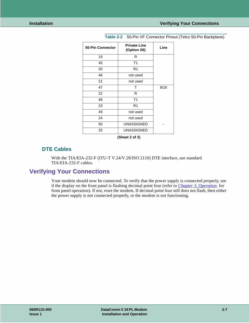
Table 2-2 50-Pin VF Connector Pinout (Telco 50-Pin Backplane)
50-Pin ConnectorPrivate Line (Option X6)
Line
26 T 1/9
1 R
27 T1
2 R1
28 not used
3 not used
29 T 2/10
4 R
30 T1
5 R1
31 not used
6 not used
32 T 3/11
7 R
33 T1
8 R1
34 not used
9 not used 3/11
35 T 4/12
10 R
36 T1
11 R1
37 not used
12 not used
38 T 5/13
13 R
39 T1
14 R1
40 not used
15 not used
41 T 6/14
16 R
42 T1
17 R1
43 not used
18 not used
44 T 7/15
(Sheet 1 of 2)
2-6 DataComm V.34 PL Modem 060R115-000Installation and Operation Issue 1
Installation Verifying Your Connections
ly, see
ither
DTE Cables
With the TIA/EIA-232-F (ITU-T V.24/V.28/ISO 2110) DTE interface, use standard TIA/EIA-232-F cables.
Verifying Your ConnectionsYour modem should now be connected. To verify that the power supply is connected properif the display on the front panel is flashing decimal point four (refer to Chapter 3, Operation for front panel operation). If not, reset the modem. If decimal point four still does not flash, then ethe power supply is not connected properly, or the modem is not functioning.
19 R
45 T1
20 R1
46 not used
21 not used
47 T 8/16
22 R
48 T1
23 R1
49 not used
24 not used
50 UNASSIGNED -
25 UNASSIGNED
Table 2-2 50-Pin VF Connector Pinout (Telco 50-Pin Backplane)
50-Pin ConnectorPrivate Line (Option X6)
Line
(Sheet 2 of 2)
060R115-000 DataComm V.34 PL Modem 2-7Issue 1 Installation and Operation
Installation Verifying Your Connections
2-8 DataComm V.34 PL Modem 060R115-000Installation and Operation Issue 1
ans of
ation
Chapter 3: Operation
Overview
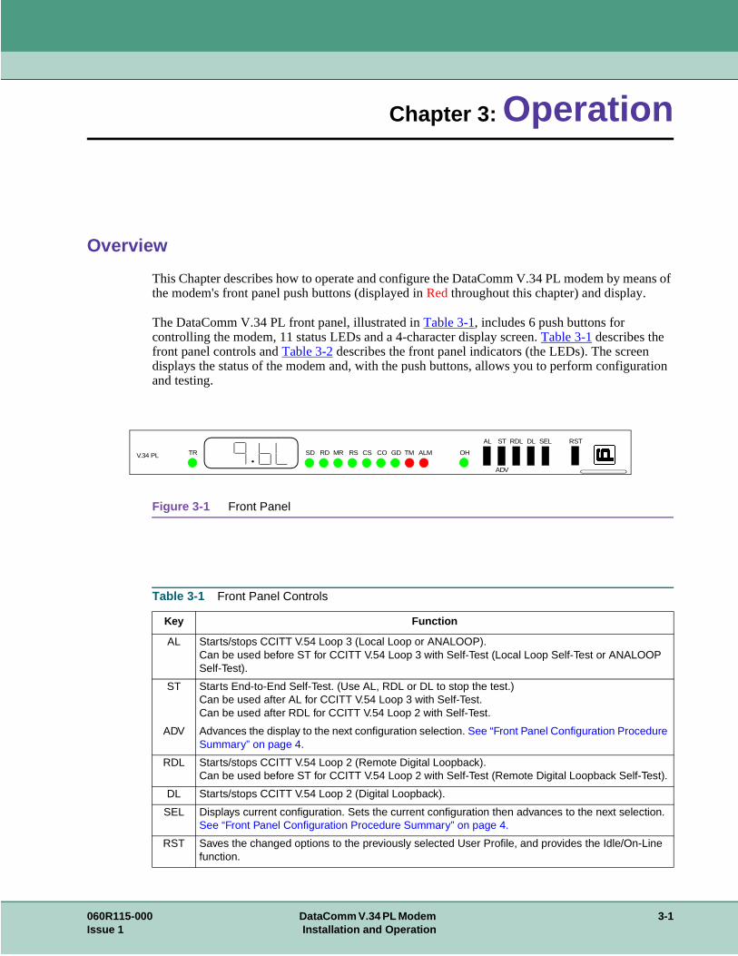
This Chapter describes how to operate and configure the DataComm V.34 PL modem by methe modem's front panel push buttons (displayed in Red throughout this chapter) and display.
The DataComm V.34 PL front panel, illustrated in Table 3-1, includes 6 push buttons for controlling the modem, 11 status LEDs and a 4-character display screen. Table 3-1 describes the front panel controls and Table 3-2 describes the front panel indicators (the LEDs). The screen displays the status of the modem and, with the push buttons, allows you to perform configurand testing.
Figure 3-1 Front Panel
Table 3-1 Front Panel Controls
Key Function
AL Starts/stops CCITT V.54 Loop 3 (Local Loop or ANALOOP).Can be used before ST for CCITT V.54 Loop 3 with Self-Test (Local Loop Self-Test or ANALOOP Self-Test).
ST Starts End-to-End Self-Test. (Use AL, RDL or DL to stop the test.)Can be used after AL for CCITT V.54 Loop 3 with Self-Test.Can be used after RDL for CCITT V.54 Loop 2 with Self-Test.
ADV Advances the display to the next configuration selection. See “Front Panel Configuration Procedure Summary” on page 4.
RDL Starts/stops CCITT V.54 Loop 2 (Remote Digital Loopback).Can be used before ST for CCITT V.54 Loop 2 with Self-Test (Remote Digital Loopback Self-Test).
DL Starts/stops CCITT V.54 Loop 2 (Digital Loopback).
SEL Displays current configuration. Sets the current configuration then advances to the next selection. See “Front Panel Configuration Procedure Summary” on page 4.
RST Saves the changed options to the previously selected User Profile, and provides the Idle/On-Line function.
V.34 PL TR SD RD MR RS CS CO GD TM ALM OH
AL ST RDL DL SEL RST
ADV
060R115-000 DataComm V.34 PL Modem 3-1Issue 1 Installation and Operation
Operation
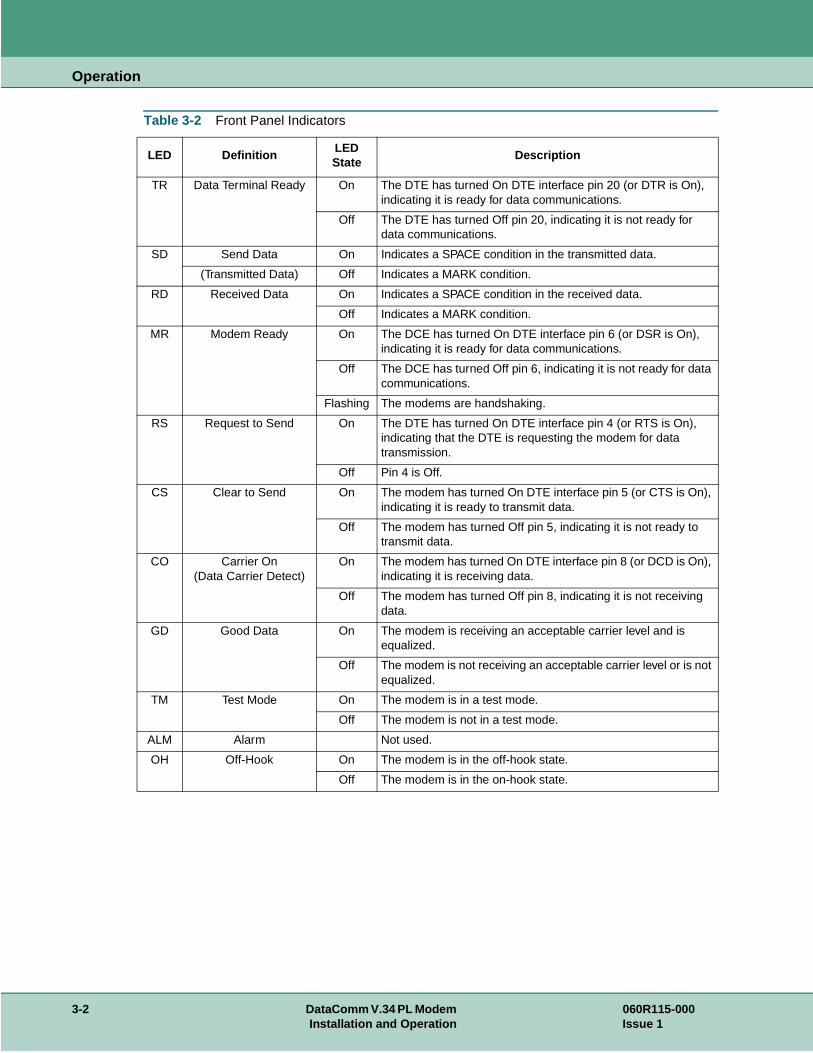
Table 3-2 Front Panel Indicators
LED DefinitionLED State
Description
TR Data Terminal Ready On The DTE has turned On DTE interface pin 20 (or DTR is On), indicating it is ready for data communications.
Off The DTE has turned Off pin 20, indicating it is not ready for data communications.
SD Send Data On Indicates a SPACE condition in the transmitted data.
(Transmitted Data) Off Indicates a MARK condition.
RD Received Data On Indicates a SPACE condition in the received data.
Off Indicates a MARK condition.
MR Modem Ready On The DCE has turned On DTE interface pin 6 (or DSR is On), indicating it is ready for data communications.
Off The DCE has turned Off pin 6, indicating it is not ready for data communications.
Flashing The modems are handshaking.
RS Request to Send On The DTE has turned On DTE interface pin 4 (or RTS is On), indicating that the DTE is requesting the modem for data transmission.
Off Pin 4 is Off.
CS Clear to Send On The modem has turned On DTE interface pin 5 (or CTS is On), indicating it is ready to transmit data.
Off The modem has turned Off pin 5, indicating it is not ready to transmit data.
CO Carrier On(Data Carrier Detect)
On The modem has turned On DTE interface pin 8 (or DCD is On), indicating it is receiving data.
Off The modem has turned Off pin 8, indicating it is not receiving data.
GD Good Data On The modem is receiving an acceptable carrier level and is equalized.
Off The modem is not receiving an acceptable carrier level or is not equalized.
TM Test Mode On The modem is in a test mode.
Off The modem is not in a test mode.
ALM Alarm Not used.
OH Off-Hook On The modem is in the off-hook state.
Off The modem is in the on-hook state.
3-2 DataComm V.34 PL Modem 060R115-000Installation and Operation Issue 1
Operation Operating Procedures
. It ll as
eed for
the
Operating ProceduresThe DataComm V.34 PL allows you to perform a number of operations from the front paneldisplays status information and allows you to configure some aspects of the modem, as weperform diagnostics.
Status
When the modem is first powered up, the display test shows 8.8.8.8. then momentarily gdc followed by a flashing decimal point. This is followed by the leased-line handshake mode. When modem is in handshake mode, the MR LED flashes along with a flashing decimal point. The GD LED is off.
If the DCE speed changes while the modem is in data mode, the modem displays the new sptwo seconds.
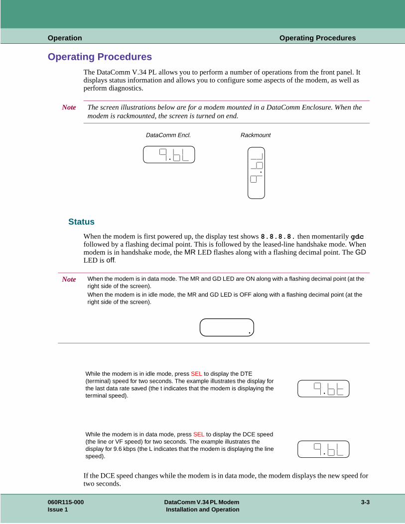
Note The screen illustrations below are for a modem mounted in a DataComm Enclosure. Whenmodem is rackmounted, the screen is turned on end.
DataComm Encl. Rackmount
Note When the modem is in data mode. The MR and GD LED are ON along with a flashing decimal point (at the right side of the screen).When the modem is in idle mode, the MR and GD LED is OFF along with a flashing decimal point (at the right side of the screen).
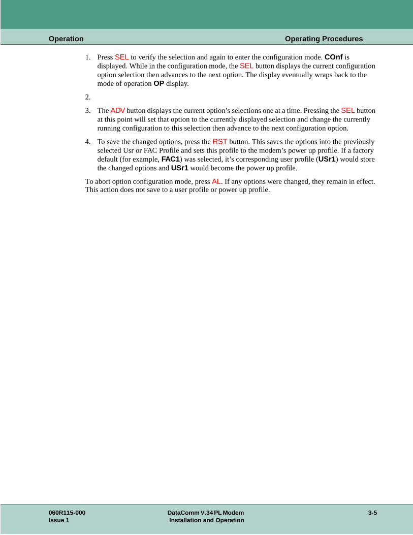
While the modem is in idle mode, press SEL to display the DTE (terminal) speed for two seconds. The example illustrates the display for the last data rate saved (the t indicates that the modem is displaying the terminal speed).
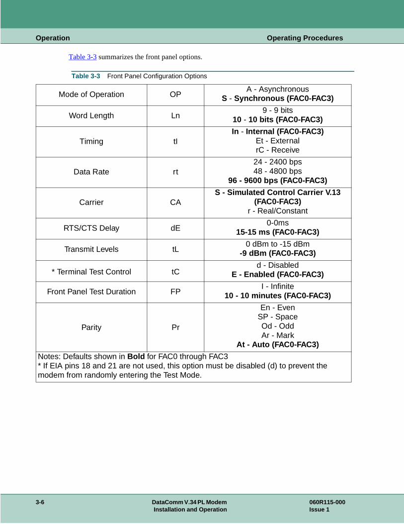
While the modem is in data mode, press SEL to display the DCE speed (the line or VF speed) for two seconds. The example illustrates the display for 9.6 kbps (the L indicates that the modem is displaying the line speed).
060R115-000 DataComm V.34 PL Modem 3-3Issue 1 Installation and Operation
Operation Operating Procedures
. As
e idle
e
re 4 ate . The
h
Configuration
The DataComm V.34 PL leased-line only modem allows you to select a configuration profilesoon as it is powered up, it performs a display test then displays “gdc ” momentarily, then continuously enters the leased line handshake mode.
To configure the modem you must first place the modem in the idle mode. (the modem is in thmode if the decimal point at the far right of the display is flashing and the front panel MR and GD LEDS are OFF. Press the front panel RST button to enter the idle mode. This may take four to fivseconds after the button is pressed.
To scroll though the profile configurations, press ADV. Profiles include FAC0 through FAC3 and USr0 through USr3.
Front Panel Configuration Procedure Summary
Before attempting to configure the DataComm V.34 PL you must identify whether you requiWire (4W) or 2 Wire (2W) Private Line operation and whether you want the answer or originfunction. Then chose the appropriate factory fixed default followed by the appropriate optionsMain Profile Menu is shown below:
To enter configuration mode press SEL, then press ADV (within two seconds). The modem briefly displays the last profile saved or selected from the front panel. The example illustrates the display for FACtory (fixed) profile 0. Once in configuration mode, there is a slight delay between the switch entry and the next LED update. Do not press the switch until the LED display updates, you may inadvertently select the next entry.
-
FAC0 (4W Orig.)Recalls factory default 0 profile
(when saved, resets USr0 to FAC0 defaults)
FAC1 (4W Ans.)Recalls factory default 1 profile
(when saved, resets USr1 to FAC1 defaults)
FAC2 (2W Orig.)Recalls factory default 2 profile
(when saved, resets USr2 to FAC2 defaults)
FAC3 (2W Ans.)Recalls factory default 3 profile
(when saved, resets USr3 to FAC3 defaults)
USr0 4-wire, Originate
USr1 4-wire, Answer
USr2 2-wire, Originate
USr3 2-wire, Answer
rEL Displays firmware version
Note You must start with a factory fixed default of FAC0, FAC1, FAC2 or FAC3 for first time configuration setup. For subsequent configuration changes you would choose USr1 througUSr3 depending on which USr profile the options were stored in.
3-4 DataComm V.34 PL Modem 060R115-000Installation and Operation Issue 1
Operation Operating Procedures
the
ntly
ly tory
t.
1. Press SEL to verify the selection and again to enter the configuration mode. COnf is displayed. While in the configuration mode, the SEL button displays the current configurationoption selection then advances to the next option. The display eventually wraps back to mode of operation OP display.
2.
3. The ADV button displays the current option’s selections one at a time. Pressing the SEL button at this point will set that option to the currently displayed selection and change the currerunning configuration to this selection then advance to the next configuration option.
4. To save the changed options, press the RST button. This saves the options into the previousselected Usr or FAC Profile and sets this profile to the modem’s power up profile. If a facdefault (for example, FAC1) was selected, it’s corresponding user profile (USr1) would store the changed options and USr1 would become the power up profile.
To abort option configuration mode, press AL. If any options were changed, they remain in effecThis action does not save to a user profile or power up profile.
060R115-000 DataComm V.34 PL Modem 3-5Issue 1 Installation and Operation
Operation Operating Procedures
Table 3-3 summarizes the front panel options.
Table 3-3 Front Panel Configuration Options
Mode of Operation OPA - Asynchronous
S - Synchronous (FAC0-FAC3)
Word Length Ln9 - 9 bits
10 - 10 bits (FAC0-FAC3)
Timing tIIn - Internal (FAC0-FAC3)
Et - ExternalrC - Receive
Data Rate rt24 - 2400 bps48 - 4800 bps
96 - 9600 bps (FAC0-FAC3)
Carrier CAS - Simulated Control Carrier V.13
(FAC0-FAC3)r - Real/Constant
RTS/CTS Delay dE0-0ms
15-15 ms (FAC0-FAC3)
Transmit Levels tL0 dBm to -15 dBm
-9 dBm (FAC0-FAC3)
* Terminal Test Control tCd - Disabled
E - Enabled (FAC0-FAC3)
Front Panel Test Duration FPI - Infinite
10 - 10 minutes (FAC0-FAC3)
Parity Pr
En - EvenSP - SpaceOd - OddAr - Mark
At - Auto (FAC0-FAC3)
Notes: Defaults shown in Bold for FAC0 through FAC3* If EIA pins 18 and 21 are not used, this option must be disabled (d) to prevent the modem from randomly entering the Test Mode.
3-6 DataComm V.34 PL Modem 060R115-000Installation and Operation Issue 1
Operation Operating Procedures
d,
inuous d rate, n two
er 4-
ous or
nother all the
th a ) speed, able to
enter
line).
e ITU-em's
rom the
Private Line Operation [FAC0 - FAC3 or USr0 - USr3]
The DataComm V.34 PL modem is configured to operate over a point-to-point, unconditionevoice grade private line (speech band leased line).
Point-to-point private lines rented from the telephone company are dedicated, direct, semi-permanent phone line connections between two locations. In applications that require a contdata transfer between fixed points, it may be more economical to rent a private line at a fixethan to pay monthly long distance charges for dial up calls. The communication link betweemultiplexers will generally involve a modem operating over private lines.
Two-wire or Four-wire Selection
The DataComm V.34 PL modem is capable of operation on private line networks, using eithwire or 2-wire circuits.
In any private line connection, first designate one modem as the originate modem FAC0 (4W)/FAC2 (2W) and the other as the answer modem FAC1 (4W)/FAC3 (2W). Next, configure both modems for the type of communication they are intended to perform: these include synchronasynchronous modes, DTE data rate, etc.
Data Mode
The DataComm V.34 PL modem is in data mode while it has a telephone line connection to amodem or is in the process of establishing a connection. In Data Mode the modem transmitsdata it receives from the DTE over the phone line.
In data mode the modem can operate either asynchronously or synchronously.
Each telephone line connection (private line) between two modems in data mode begins wihandshaking sequence. During that sequence the modems determine the VF (telephone lineand related parameters for the data link. Configuration determines the range of choices availthe modem in the negotiation process.
The presence of a carrier from a remote modem causes the DataComm V.34 PL modem todata mode and assert a Data Carrier Detect (DCD) signal to it’s DTE.
Asynchronous Operation [OP.A]
When you select asynchronous operating mode (OP.A from the front panel), the DataComm V.34PL modem operates asynchronously while on-line (data mode - connected to the telephone
Synchronous Operation [OP.S]
Selecting OP.S from the front panel selects synchronous operation.
V.13 Simulated Carrier Mode [CA.S]
V.13 mode is a simulated controlled carrier mode designed for polling applications. It uses thT V.13 RTS/DCD signaling method to control the remote modem's DCD lead via the local modRTS lead. It can be used for both synchronous and asynchronous data. To select this mode ffront panel, select CA.S.
060R115-000 DataComm V.34 PL Modem 3-7Issue 1 Installation and Operation
Operation Operating Procedures
or
arrier
It mat. The es to
h data.
e
anual
ys ides nsmit
eived. smit
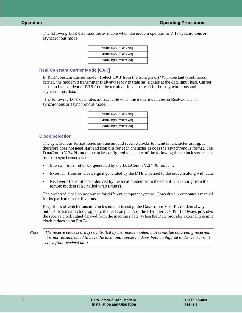
The following DTE data rates are available when the modem operates in V.13 synchronousasynchronous mode:
Real/Constant Carrier Mode [CA.r]
In Real/Constant Carrier mode - (select CA.r from the front panel) With constant (continuous) carrier, the modem’s transmitter is always ready to transmit signals at the data input lead. Cstays on independent of RTS from the terminal. It can be used for both synchronous and asynchronous data.
The following DTE data rates are available when the modem operates in Real/Constant synchronous or asynchronous mode:
Clock Selection
The synchronous format relies on transmit and receive clocks to maintain character timing. therefore does not need start and stop bits for each character as does the asynchronous forDataComm V.34 PL modem can be configured to use one of the following three clock sourctransmit synchronous data:
• Internal - transmit clock generated by the DataComm V.34 PL modem.
• External - transmit clock signal generated by the DTE is passed to the modem along wit
• Receiver - transmit clock derived by the local modem from the data it is receiving from thremote modem (also called wrap timing).
The preferred clock source varies for different computer systems. Consult your computer's mfor its particular specifications.
Regardless of which transmit clock source it is using, the DataComm V.34 PL modem alwaoutputs its transmit clock signal to the DTE on pin 15 of the EIA interface. Pin 17 always provthe receive clock signal derived from the incoming data. When the DTE provides external traclock it does so on Pin 24.
9600 bps (enter 96)
4800 bps (enter 48)
2400 bps (enter 24)
9600 bps (enter 96)
4800 bps (enter 48)
2400 bps (enter 24)
Note The receive clock is always controlled by the remote modem that sends the data being recIt is not recommended to have the local and remote modems both configured to derive tranclock from received data.
3-8 DataComm V.34 PL Modem 060R115-000Installation and Operation Issue 1

Operation Operating Procedures
w or with e
on can
tline
s.
n
Transmit Level
It is possible in private line operation for the transmit levels of the modems to be either too lotoo high. When that is the case the connection usually will not be dependable and will be fillederrors. To correct such situations, the transmit level of the DataComm V.34 PL for private linoperation can be configured in 1 dBm increments between 0 dBm and -15 dBm. This selectibe done from the front panel by entering tL then 0 to 15. -9dBm is the default.
Automatic and Manual Handshaking
The modems can be put into private line idle via the front panel RST button. From idle, the RST button can be used to initiate a new connection. Once told to handshake, the modems will continuously try to complete a handshake.
When communicating with a different modem in private line operations, the following steps ouhow to configure the modems:
1. Configure both modems for the type of communications they are intended to perform.
2. Configure the DataComm V.34 PL modem as the Originate modem, selecting FAC0, FAC2 .
3. Again, use the RST button to permanently store the current configurations for both modem
Testing the Modem
Chapter 6 describes basic diagnostics.
Diagnostics
Note It is recommended that you permanently store the above settings by pressing the RST front panel button. The modems are now ready for private line communications.
Note When the modem is in synchronous mode, you must press the front panel RST button to enter idle.
Note You can perform private line "back-to-back" testing with the supplied 8-pin cable, but only itwo-wire mode with the transmit level set to -15 dBm. For back-to-back testing in four-wire mode, use GDC cable P/N 024H207-XXX.
The DataComm V.34 PL allows you to perform the diagnostics described below. If you attempt to start a test which cannot be run (e.g., End-to-End Self-Test when the local modem is not connected to another modem), the modem displays nA (not applicable).
060R115-000 DataComm V.34 PL Modem 3-9Issue 1 Installation and Operation
Operation Operating Procedures
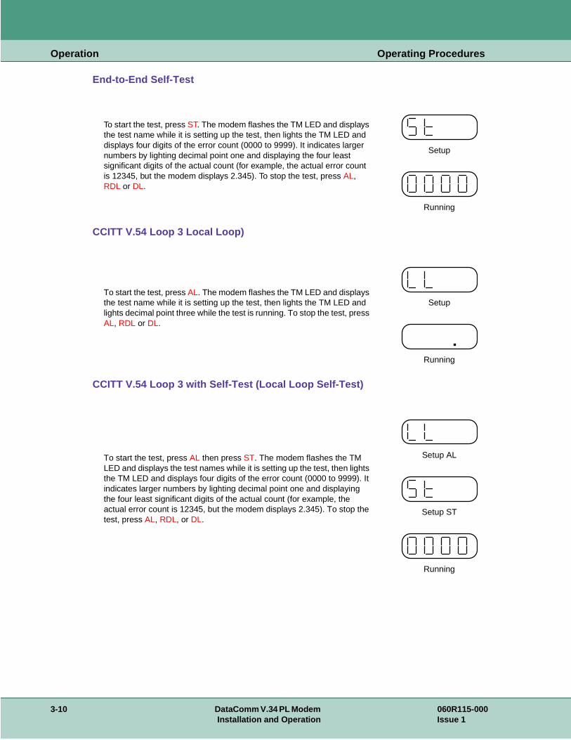
End-to-End Self-Test
CCITT V.54 Loop 3 Local Loop)
CCITT V.54 Loop 3 with Self-Test (Local Loop Self-Test)
To start the test, press ST. The modem flashes the TM LED and displays the test name while it is setting up the test, then lights the TM LED and displays four digits of the error count (0000 to 9999). It indicates larger numbers by lighting decimal point one and displaying the four least significant digits of the actual count (for example, the actual error count is 12345, but the modem displays 2.345). To stop the test, press AL, RDL or DL.
Setup
Running
To start the test, press AL. The modem flashes the TM LED and displays the test name while it is setting up the test, then lights the TM LED and lights decimal point three while the test is running. To stop the test, press AL, RDL or DL.
Setup
Running
To start the test, press AL then press ST. The modem flashes the TM LED and displays the test names while it is setting up the test, then lights the TM LED and displays four digits of the error count (0000 to 9999). It indicates larger numbers by lighting decimal point one and displaying the four least significant digits of the actual count (for example, the actual error count is 12345, but the modem displays 2.345). To stop the test, press AL, RDL, or DL.
Setup AL
Setup ST
Running
3-10 DataComm V.34 PL Modem 060R115-000Installation and Operation Issue 1
Operation Operating Procedures
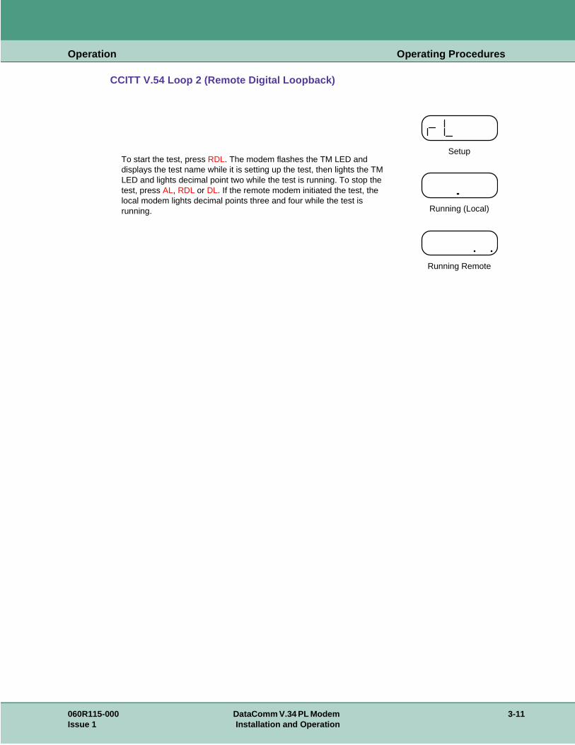
CCITT V.54 Loop 2 (Remote Digital Loopback)
To start the test, press RDL. The modem flashes the TM LED and displays the test name while it is setting up the test, then lights the TM LED and lights decimal point two while the test is running. To stop the test, press AL, RDL or DL. If the remote modem initiated the test, the local modem lights decimal points three and four while the test is running.
Setup
Running (Local)
Running Remote
060R115-000 DataComm V.34 PL Modem 3-11Issue 1 Installation and Operation

Operation Operating Procedures
3-12 DataComm V.34 PL Modem 060R115-000Installation and Operation Issue 1
isolate
with
r will
Chapter 4: Tests
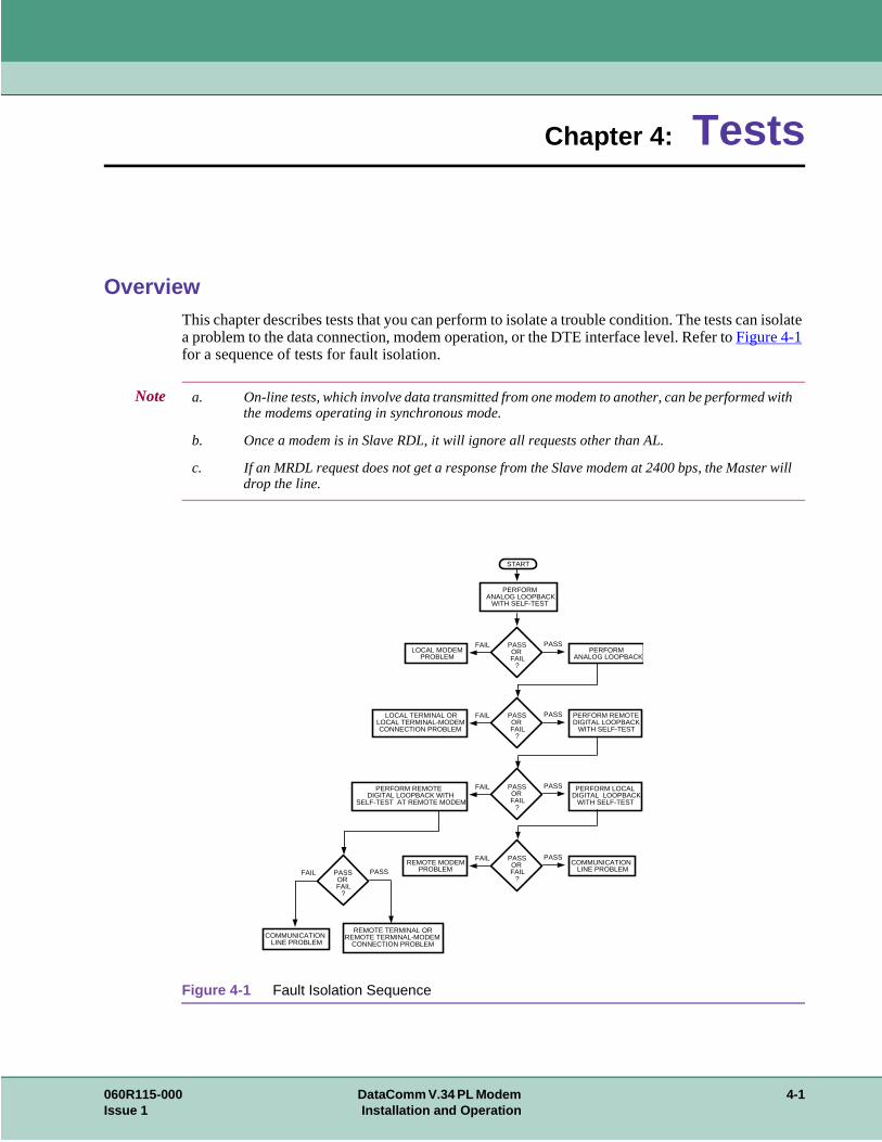
OverviewThis chapter describes tests that you can perform to isolate a trouble condition. The tests cana problem to the data connection, modem operation, or the DTE interface level. Refer to Figure 4-1 for a sequence of tests for fault isolation.
Figure 4-1 Fault Isolation Sequence
Note a. On-line tests, which involve data transmitted from one modem to another, can be performedthe modems operating in synchronous mode.
b. Once a modem is in Slave RDL, it will ignore all requests other than AL.
c. If an MRDL request does not get a response from the Slave modem at 2400 bps, the Mastedrop the line.
PASS OR FAIL
?
PASSFAIL
PASS OR FAIL
?
PASSFAIL
PASS OR FAIL
?
PASSFAIL
PASS OR FAIL
?
PASSFAIL
PASS OR FAIL
?
PASSFAIL
PERFORM ANALOG LOOPBACK
WITH SELF-TEST
REMOTE MODEM PROBLEM
START
PERFORM ANALOG LOOPBACK
COMMUNICATION LINE PROBLEM
LOCAL MODEM PROBLEM
LOCAL TERMINAL OR LOCAL TERMINAL-MODEM CONNECTION PROBLEM
PERFORM REMOTE DIGITAL LOOPBACK WITH
SELF-TEST AT REMOTE MODEM
PERFORM LOCAL DIGITAL LOOPBACK
WITH SELF-TEST
PERFORM REMOTE DIGITAL LOOPBACK
WITH SELF-TEST
REMOTE TERMINAL OR REMOTE TERMINAL-MODEM
CONNECTION PROBLEMCOMMUNICATION
LINE PROBLEM
060R115-000 DataComm V.34 PL Modem 4-1Issue 1 Installation and Operation
Tests Analog Loopback (ANALOOP)
e tor
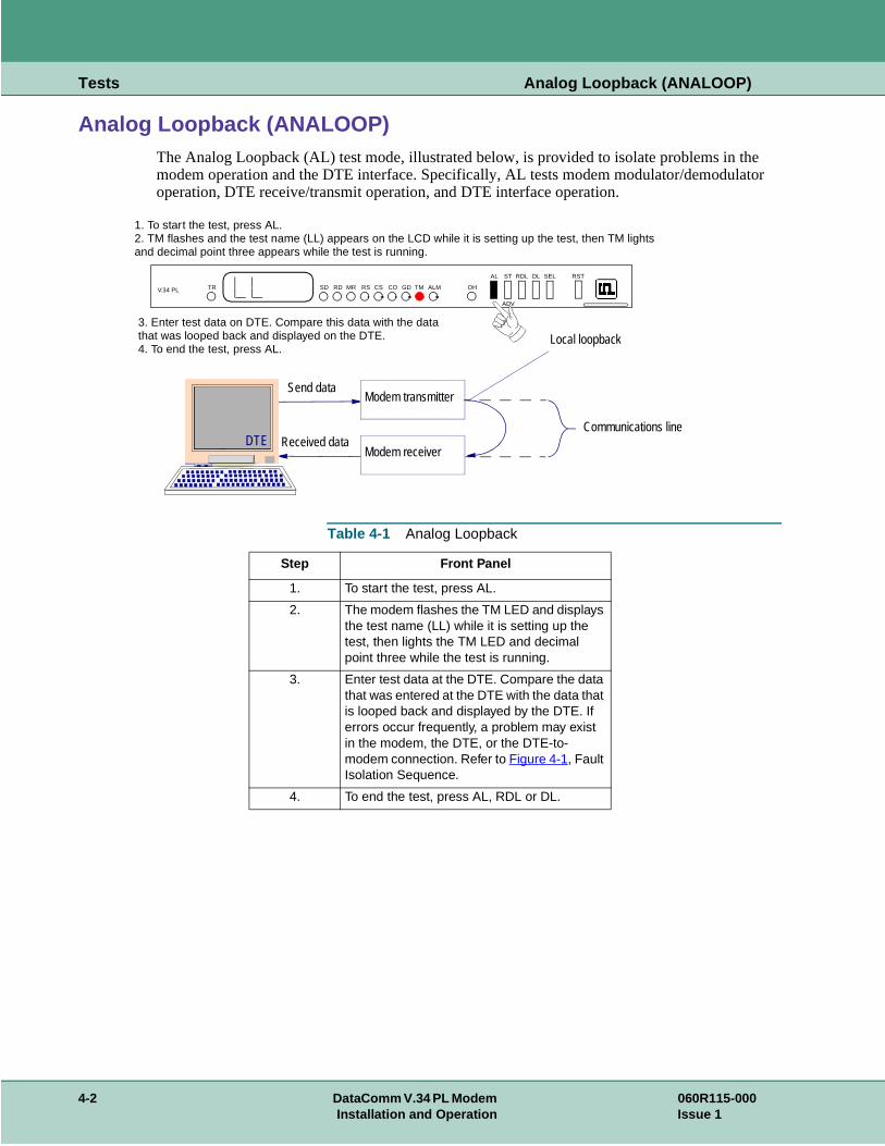
Analog Loopback (ANALOOP)The Analog Loopback (AL) test mode, illustrated below, is provided to isolate problems in thmodem operation and the DTE interface. Specifically, AL tests modem modulator/demodulaoperation, DTE receive/transmit operation, and DTE interface operation.
Table 4-1 Analog Loopback
Step Front Panel
1. To start the test, press AL.
2. The modem flashes the TM LED and displays the test name (LL) while it is setting up the test, then lights the TM LED and decimal point three while the test is running.
3. Enter test data at the DTE. Compare the data that was entered at the DTE with the data that is looped back and displayed by the DTE. If errors occur frequently, a problem may exist in the modem, the DTE, or the DTE-to-modem connection. Refer to Figure 4-1, Fault Isolation Sequence.
4. To end the test, press AL, RDL or DL.
Modem transmitter
Modem receiver
Send data
Received dataDTECommunications line
Local loopback
V.34 PL TR SD RD MR RS CS CO GD TM ALM OH
AL ST RDL DL SEL RST
ADV
1. To start the test, press AL.2. TM flashes and the test name (LL) appears on the LCD while it is setting up the test, then TM lights and decimal point three appears while the test is running.
3. Enter test data on DTE. Compare this data with the datathat was looped back and displayed on the DTE.4. To end the test, press AL.
4-2 DataComm V.34 PL Modem 060R115-000Installation and Operation Issue 1
Tests Analog Loopback with Self-Test
elf-tern is es a 511 r you to
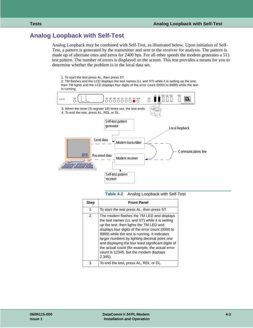
Analog Loopback with Self-TestAnalog Loopback may be combined with Self-Test, as illustrated below. Upon initiation of STest, a pattern is generated by the transmitter and sent to the receiver for analysis. The patmade up of alternate ones and zeros for 2400 bps. For all other speeds the modem generattest pattern. The number of errors is displayed on the screen. This test provides a means fodetermine whether the problem is in the local data set.
Table 4-2 Analog Loopback with Self-Test
Step Front Panel
1. To start the test press AL, then press ST.
2. The modem flashes the TM LED and displays the test names (LL and ST) while it is setting up the test, then lights the TM LED and displays four digits of the error count (0000 to 9999) while the test is running. It indicates larger numbers by lighting decimal point one and displaying the four least significant digits of the actual count (for example, the actual error count is 12345, but the modem displays 2.345).
3. To end the test, press AL, RDL or DL.
Modem transmitter
Modem receiver
Send data
Received dataDTECommunications line
Local loopback
Self-test pattern generator
Self-test pattern receiver
V.34 PL TR SD RD MR RS CS CO GD TM ALM OH
AL ST RDL DL SEL RST
ADV
1. To start the test press AL, then press ST.2. TM flashes and the LCD displays the test names (LL and ST) while it is setting up the test,then TM lights and the LCD displays four digits of the error count (0000 to 9999) while the testis running.
3. When the timer (S-register 18) times out, the test ends.4. To end the test, press AL, RDL or DL.
060R115-000 DataComm V.34 PL Modem 4-3Issue 1 Installation and Operation
Tests Digital Loopback
front back, m a amped
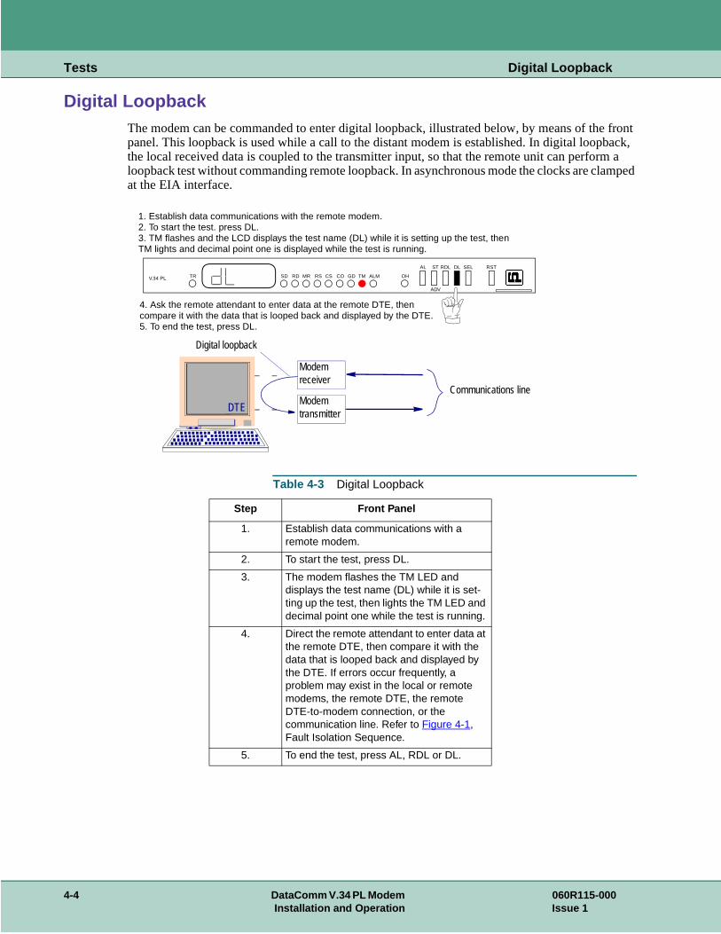
Digital LoopbackThe modem can be commanded to enter digital loopback, illustrated below, by means of thepanel. This loopback is used while a call to the distant modem is established. In digital loopthe local received data is coupled to the transmitter input, so that the remote unit can perforloopback test without commanding remote loopback. In asynchronous mode the clocks are clat the EIA interface.
Table 4-3 Digital Loopback
Step Front Panel
1. Establish data communications with a remote modem.
2. To start the test, press DL.
3. The modem flashes the TM LED and displays the test name (DL) while it is set-ting up the test, then lights the TM LED and decimal point one while the test is running.
4. Direct the remote attendant to enter data at the remote DTE, then compare it with the data that is looped back and displayed by the DTE. If errors occur frequently, a problem may exist in the local or remote modems, the remote DTE, the remote DTE-to-modem connection, or the communication line. Refer to Figure 4-1, Fault Isolation Sequence.
5. To end the test, press AL, RDL or DL.
ModemtransmitterDTE
Digital loopback
Modemreceiver
Communications line
V.34 PL TR SD RD MR RS CS CO GD TM ALM OH
AL ST RDL DL SEL RST
ADV
1. Establish data communications with the remote modem.2. To start the test. press DL.3. TM flashes and the LCD displays the test name (DL) while it is setting up the test, thenTM lights and decimal point one is displayed while the test is running.
4. Ask the remote attendant to enter data at the remote DTE, then compare it with the data that is looped back and displayed by the DTE.5. To end the test, press DL.
4-4 DataComm V.34 PL Modem 060R115-000Installation and Operation Issue 1
Tests Remote Digital Loopback
ded a call eceived e local
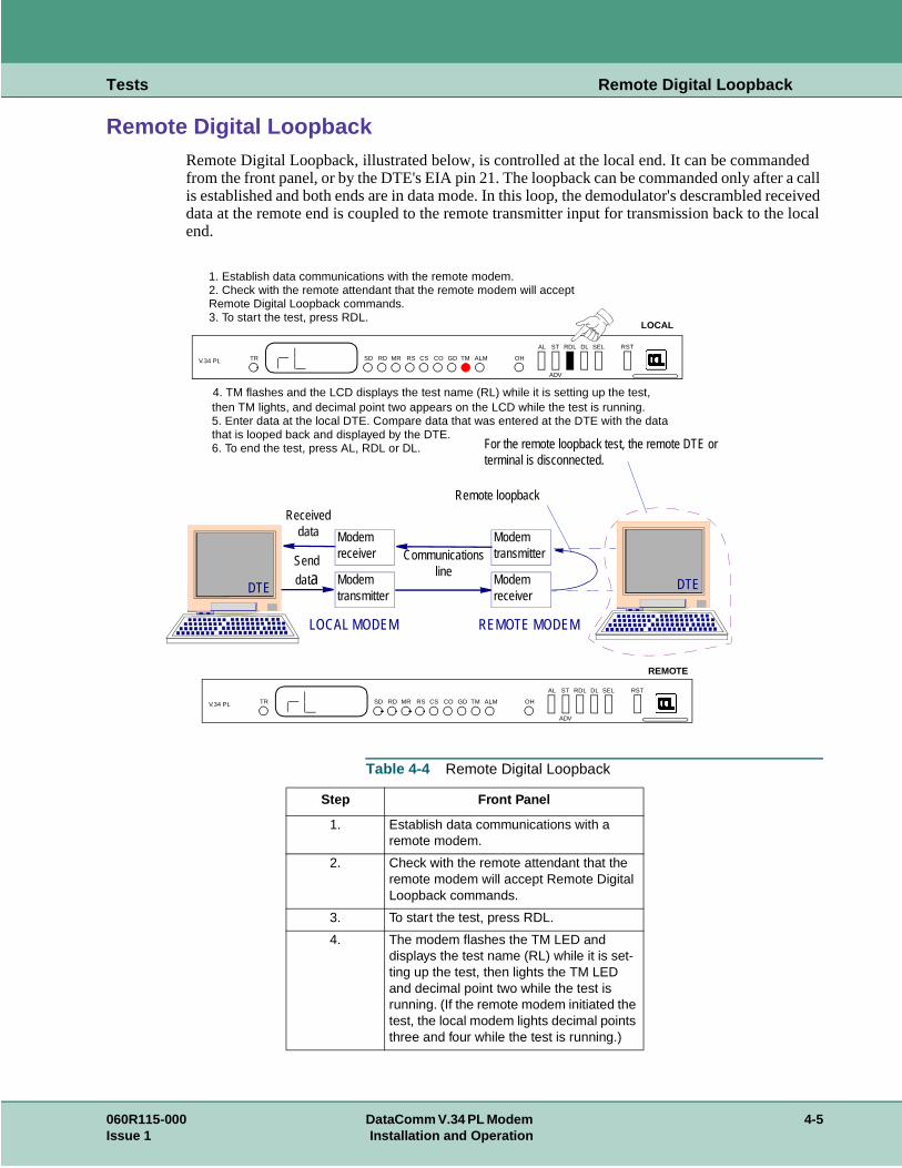
Remote Digital LoopbackRemote Digital Loopback, illustrated below, is controlled at the local end. It can be commanfrom the front panel, or by the DTE's EIA pin 21. The loopback can be commanded only afteris established and both ends are in data mode. In this loop, the demodulator's descrambled rdata at the remote end is coupled to the remote transmitter input for transmission back to thend.
Table 4-4 Remote Digital Loopback
Step Front Panel
1. Establish data communications with a remote modem.
2. Check with the remote attendant that the remote modem will accept Remote Digital Loopback commands.
3. To start the test, press RDL.
4. The modem flashes the TM LED and displays the test name (RL) while it is set-ting up the test, then lights the TM LED and decimal point two while the test is running. (If the remote modem initiated the test, the local modem lights decimal points three and four while the test is running.)
ModemtransmitterDTE
Communicationsline
DTE
LOCAL MODEM REMOTE MODEM
Modemreceiver
Modemreceiver
Modemtransmitter
For the remote loopback test, the remote DTE or terminal is disconnected.
Senddata
Receiveddata
Remote loopback
V.34 PL TR SD RD MR RS CS CO GD TM ALM OH
AL ST RDL DL SEL RST
ADV
1. Establish data communications with the remote modem.2. Check with the remote attendant that the remote modem will acceptRemote Digital Loopback commands.3. To start the test, press RDL.
4. TM flashes and the LCD displays the test name (RL) while it is setting up the test,then TM lights, and decimal point two appears on the LCD while the test is running.5. Enter data at the local DTE. Compare data that was entered at the DTE with the datathat is looped back and displayed by the DTE.6. To end the test, press AL, RDL or DL.
V.34 PL TR SD RD MR RS CS CO GD TM ALM OH
AL ST RDL DL SEL RST
ADV
LOCAL
REMOTE
060R115-000 DataComm V.34 PL Modem 4-5Issue 1 Installation and Operation
Tests Remote Digital Loopback
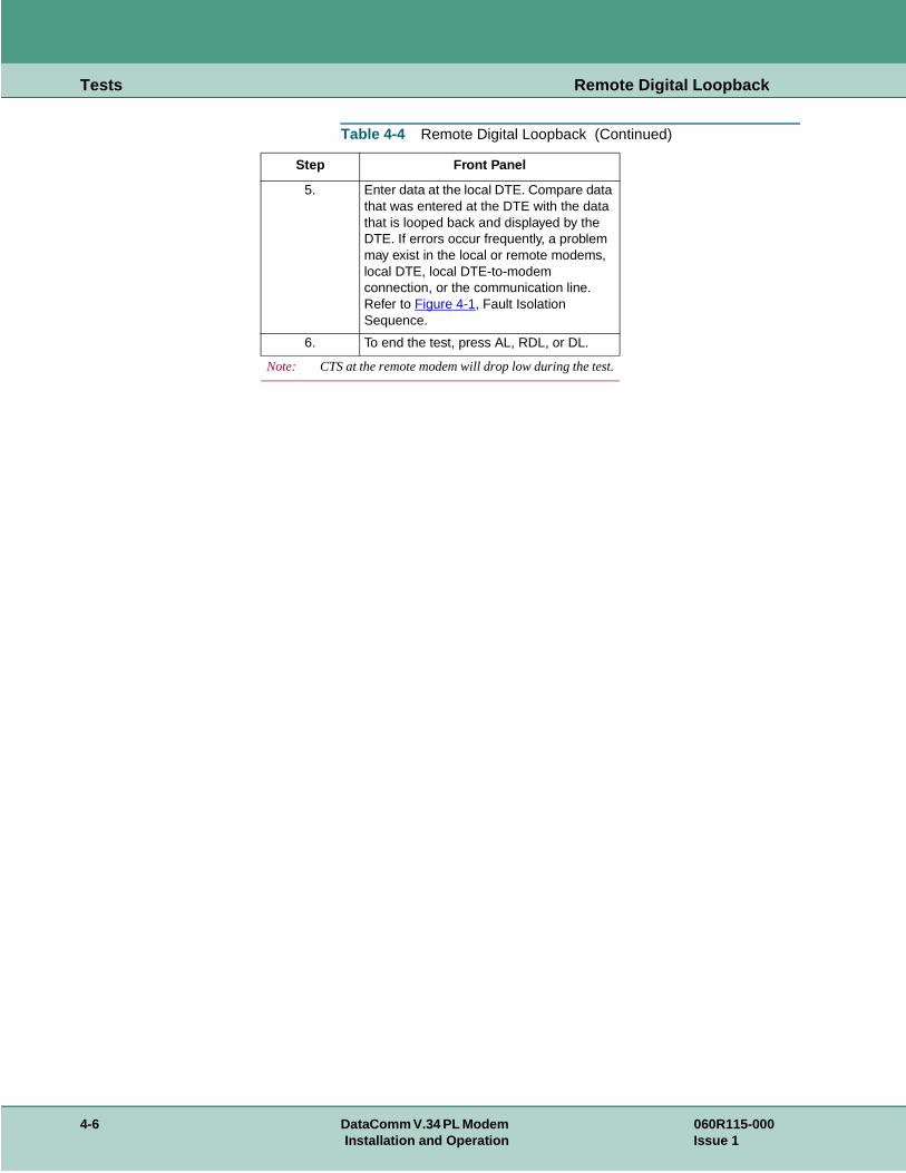
5. Enter data at the local DTE. Compare data that was entered at the DTE with the data that is looped back and displayed by the DTE. If errors occur frequently, a problem may exist in the local or remote modems, local DTE, local DTE-to-modem connection, or the communication line. Refer to Figure 4-1, Fault Isolation Sequence.
6. To end the test, press AL, RDL, or DL.
Note: CTS at the remote modem will drop low during the test.
Table 4-4 Remote Digital Loopback (Continued)
Step Front Panel
4-6 DataComm V.34 PL Modem 060R115-000Installation and Operation Issue 1
Tests Remote Digital Loopback with Self-Test
n be ished that is
remote for eds the test
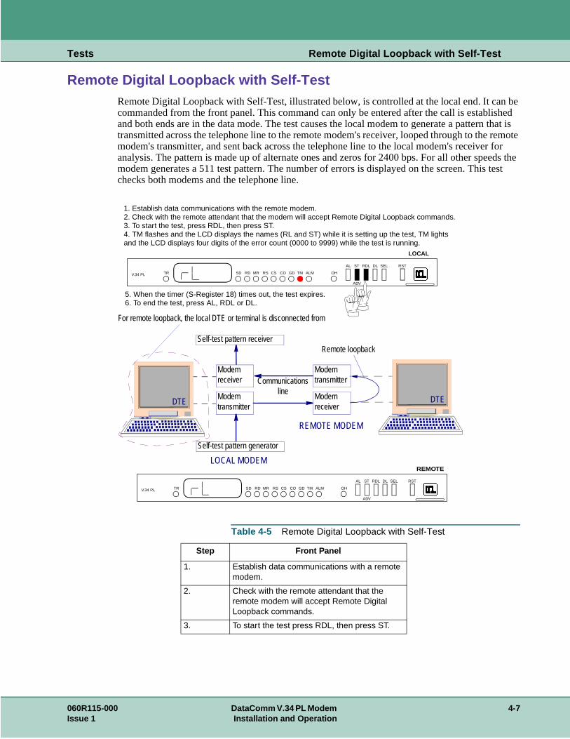
Remote Digital Loopback with Self-TestRemote Digital Loopback with Self-Test, illustrated below, is controlled at the local end. It cacommanded from the front panel. This command can only be entered after the call is establand both ends are in the data mode. The test causes the local modem to generate a patterntransmitted across the telephone line to the remote modem's receiver, looped through to themodem's transmitter, and sent back across the telephone line to the local modem's receiveranalysis. The pattern is made up of alternate ones and zeros for 2400 bps. For all other spemodem generates a 511 test pattern. The number of errors is displayed on the screen. Thischecks both modems and the telephone line.
Table 4-5 Remote Digital Loopback with Self-Test
Step Front Panel
1. Establish data communications with a remote modem.
2. Check with the remote attendant that the remote modem will accept Remote Digital Loopback commands.
3. To start the test press RDL, then press ST.
ModemtransmitterDTE
Communicationsline
Remote loopback
DTE
LOCAL MODEM
REMOTE MODEM
Modemreceiver
Modemreceiver
Modemtransmitter
Self-test pattern receiver
Self-test pattern generator
For remote loopback, the local DTE or terminal is disconnected from
V.34 PL TR SD RD MR RS CS CO GD TM ALM OH
AL ST RDL DL SEL RST
ADV
1. Establish data communications with the remote modem.2. Check with the remote attendant that the modem will accept Remote Digital Loopback commands.3. To start the test, press RDL, then press ST.4. TM flashes and the LCD displays the names (RL and ST) while it is setting up the test, TM lights and the LCD displays four digits of the error count (0000 to 9999) while the test is running.
5. When the timer (S-Register 18) times out, the test expires.6. To end the test, press AL, RDL or DL.
LOCAL
V.34 PL TR SD RD MR RS CS CO GD TM ALM OH
AL ST RDL DL SEL RST
ADV
REMOTE
060R115-000 DataComm V.34 PL Modem 4-7Issue 1 Installation and Operation
Tests Remote Digital Loopback with Self-Test
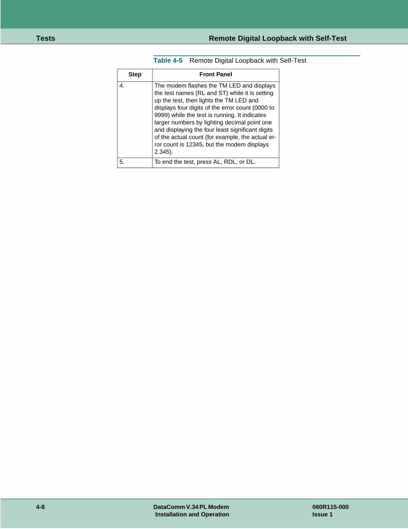
4. The modem flashes the TM LED and displays the test names (RL and ST) while it is setting up the test, then lights the TM LED and displays four digits of the error count (0000 to 9999) while the test is running. It indicates larger numbers by lighting decimal point one and displaying the four least significant digits of the actual count (for example, the actual er-ror count is 12345, but the modem displays 2.345).
5. To end the test, press AL, RDL, or DL.
Table 4-5 Remote Digital Loopback with Self-Test
Step Front Panel
4-8 DataComm V.34 PL Modem 060R115-000Installation and Operation Issue 1
Tests End-to-End Self-Test
em. It l is a pattern The dems test
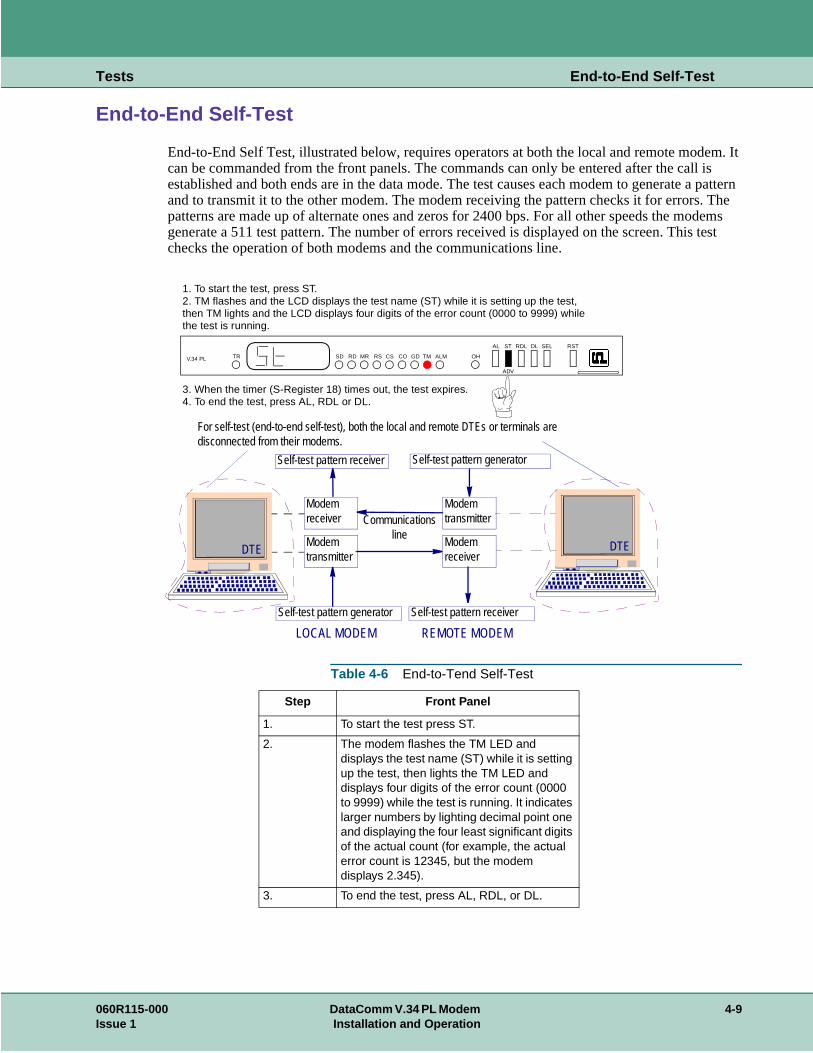
End-to-End Self-Test
End-to-End Self Test, illustrated below, requires operators at both the local and remote modcan be commanded from the front panels. The commands can only be entered after the calestablished and both ends are in the data mode. The test causes each modem to generate and to transmit it to the other modem. The modem receiving the pattern checks it for errors.patterns are made up of alternate ones and zeros for 2400 bps. For all other speeds the mogenerate a 511 test pattern. The number of errors received is displayed on the screen. Thischecks the operation of both modems and the communications line.
Table 4-6 End-to-Tend Self-Test
Step Front Panel
1. To start the test press ST.
2. The modem flashes the TM LED and displays the test name (ST) while it is setting up the test, then lights the TM LED and displays four digits of the error count (0000 to 9999) while the test is running. It indicates larger numbers by lighting decimal point one and displaying the four least significant digits of the actual count (for example, the actual error count is 12345, but the modem displays 2.345).
3. To end the test, press AL, RDL, or DL.
ModemtransmitterDTE
Communicationsline
DTE
LOCAL MODEM REMOTE MODEM
Modemreceiver
Modemreceiver
Modemtransmitter
Self-test pattern receiver
Self-test pattern generator
For self-test (end-to-end self-test), both the local and remote DTEs or terminals are disconnected from their modems.
Self-test pattern generator
Self-test pattern receiver
V.34 PL TR SD RD MR RS CS CO GD TM ALM OH
AL ST RDL DL SEL RST
ADV
1. To start the test, press ST.2. TM flashes and the LCD displays the test name (ST) while it is setting up the test,then TM lights and the LCD displays four digits of the error count (0000 to 9999) whilethe test is running.
3. When the timer (S-Register 18) times out, the test expires.4. To end the test, press AL, RDL or DL.
060R115-000 DataComm V.34 PL Modem 4-9Issue 1 Installation and Operation

Tests End-to-End Self-Test
4-10 DataComm V.34 PL Modem 060R115-000Installation and Operation Issue 1
Appendix A: Technical Specifications
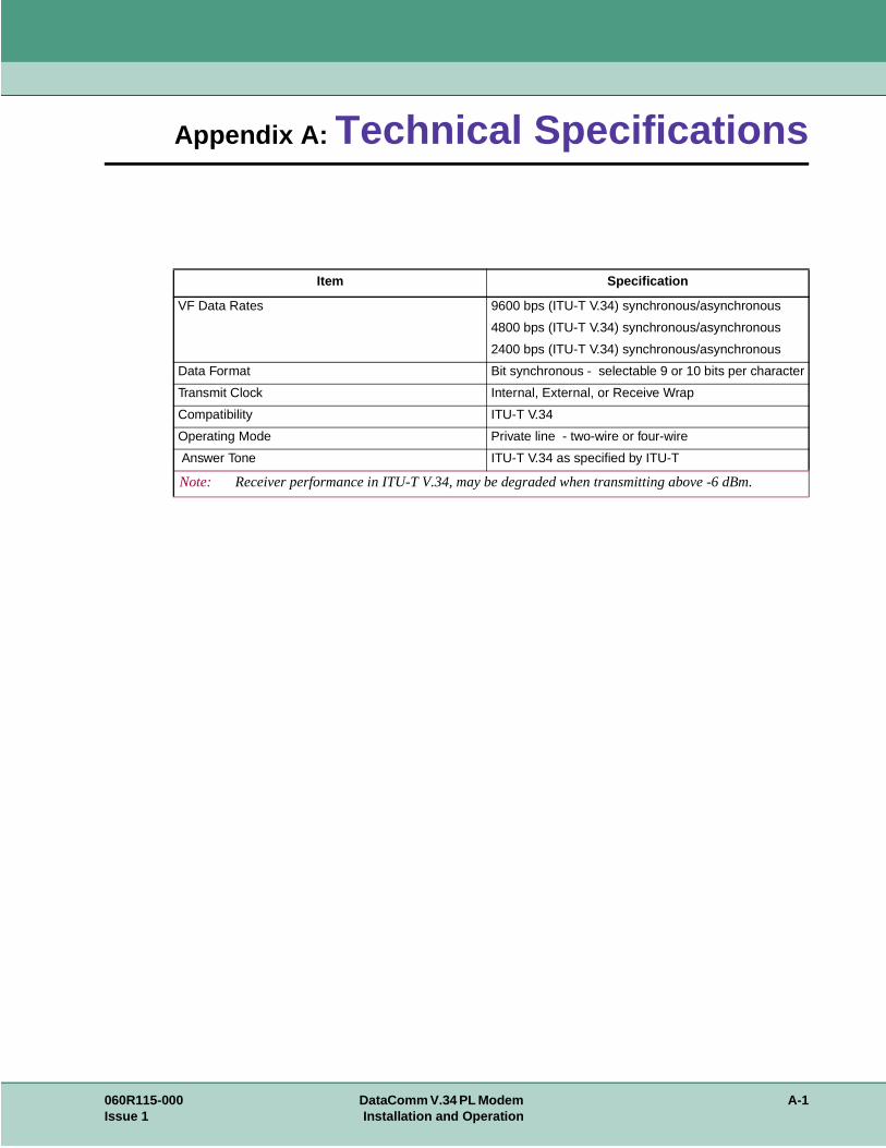
Item Specification
VF Data Rates 9600 bps (ITU-T V.34) synchronous/asynchronous
4800 bps (ITU-T V.34) synchronous/asynchronous
2400 bps (ITU-T V.34) synchronous/asynchronous
Data Format Bit synchronous - selectable 9 or 10 bits per character
Transmit Clock Internal, External, or Receive Wrap
Compatibility ITU-T V.34
Operating Mode Private line - two-wire or four-wire
Answer Tone ITU-T V.34 as specified by ITU-T
Note: Receiver performance in ITU-T V.34, may be degraded when transmitting above -6 dBm.
060R115-000 DataComm V.34 PL Modem A-1Issue 1 Installation and Operation
Technical Specifications
ec-
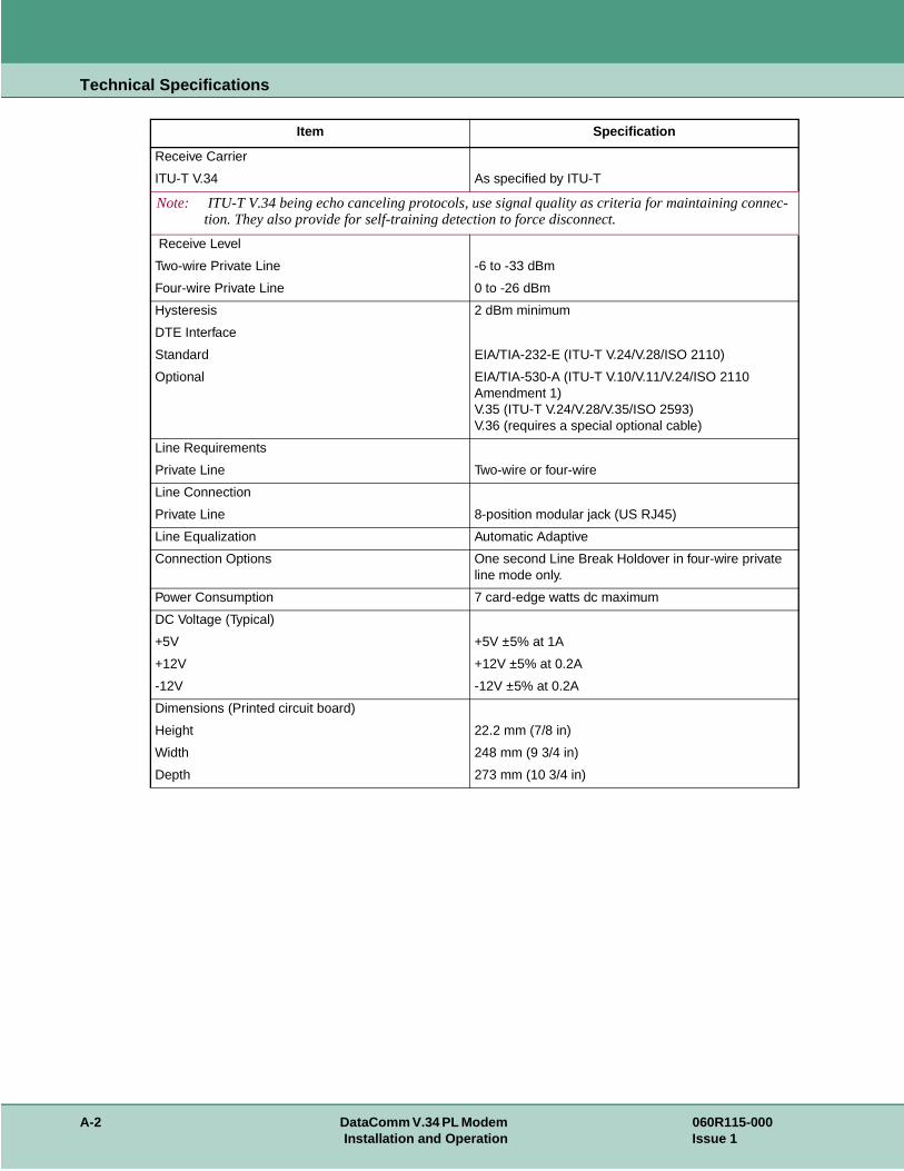
Receive Carrier
ITU-T V.34 As specified by ITU-T
Note: ITU-T V.34 being echo canceling protocols, use signal quality as criteria for maintaining conntion. They also provide for self-training detection to force disconnect.
Receive Level
Two-wire Private Line -6 to -33 dBm
Four-wire Private Line 0 to -26 dBm
Hysteresis 2 dBm minimum
DTE Interface
Standard EIA/TIA-232-E (ITU-T V.24/V.28/ISO 2110)
Optional EIA/TIA-530-A (ITU-T V.10/V.11/V.24/ISO 2110 Amendment 1)V.35 (ITU-T V.24/V.28/V.35/ISO 2593)V.36 (requires a special optional cable)
Line Requirements
Private Line Two-wire or four-wire
Line Connection
Private Line 8-position modular jack (US RJ45)
Line Equalization Automatic Adaptive
Connection Options One second Line Break Holdover in four-wire private line mode only.
Power Consumption 7 card-edge watts dc maximum
DC Voltage (Typical)
+5V +5V ±5% at 1A
+12V +12V ±5% at 0.2A
-12V -12V ±5% at 0.2A
Dimensions (Printed circuit board)
Height 22.2 mm (7/8 in)
Width 248 mm (9 3/4 in)
Depth 273 mm (10 3/4 in)
Item Specification
A-2 DataComm V.34 PL Modem 060R115-000Installation and Operation Issue 1

Technical Specifications
Temperature
Operating 0 to 50×C (32× to 122×F)
Non-operating -40 to 70×C (-40× to 158×F)
Humidity, operating Up to 95 % humidity (non-condensing)
Altitude, operating 0 m to 3,047 m (0 to 10,000 ft)
Item Specification
060R115-000 DataComm V.34 PL Modem A-3Issue 1 Installation and Operation

Technical Specifications
A-4 DataComm V.34 PL Modem 060R115-000Installation and Operation Issue 1
Appendix B: Business Equipment Interface(TIA/EIA-232-F, ITU-T V.24/V.28/ISO 2110)
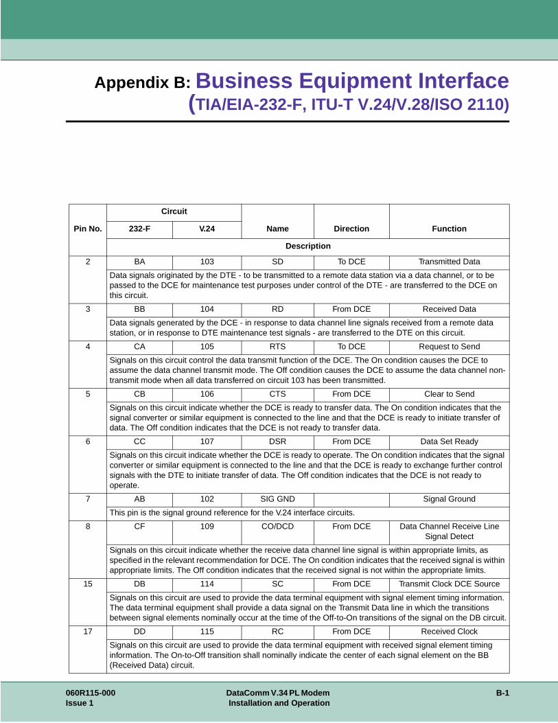
Pin No.
Circuit
Name Direction Function232-F V.24
Description
2 BA 103 SD To DCE Transmitted Data
Data signals originated by the DTE - to be transmitted to a remote data station via a data channel, or to be passed to the DCE for maintenance test purposes under control of the DTE - are transferred to the DCE on this circuit.
3 BB 104 RD From DCE Received Data
Data signals generated by the DCE - in response to data channel line signals received from a remote data station, or in response to DTE maintenance test signals - are transferred to the DTE on this circuit.
4 CA 105 RTS To DCE Request to Send
Signals on this circuit control the data transmit function of the DCE. The On condition causes the DCE to assume the data channel transmit mode. The Off condition causes the DCE to assume the data channel non-transmit mode when all data transferred on circuit 103 has been transmitted.
5 CB 106 CTS From DCE Clear to Send
Signals on this circuit indicate whether the DCE is ready to transfer data. The On condition indicates that the signal converter or similar equipment is connected to the line and that the DCE is ready to initiate transfer of data. The Off condition indicates that the DCE is not ready to transfer data.
6 CC 107 DSR From DCE Data Set Ready
Signals on this circuit indicate whether the DCE is ready to operate. The On condition indicates that the signal converter or similar equipment is connected to the line and that the DCE is ready to exchange further control signals with the DTE to initiate transfer of data. The Off condition indicates that the DCE is not ready to operate.
7 AB 102 SIG GND Signal Ground
This pin is the signal ground reference for the V.24 interface circuits.
8 CF 109 CO/DCD From DCE Data Channel Receive Line Signal Detect
Signals on this circuit indicate whether the receive data channel line signal is within appropriate limits, as specified in the relevant recommendation for DCE. The On condition indicates that the received signal is within appropriate limits. The Off condition indicates that the received signal is not within the appropriate limits.
15 DB 114 SC From DCE Transmit Clock DCE Source
Signals on this circuit are used to provide the data terminal equipment with signal element timing information. The data terminal equipment shall provide a data signal on the Transmit Data line in which the transitions between signal elements nominally occur at the time of the Off-to-On transitions of the signal on the DB circuit.
17 DD 115 RC From DCE Received Clock
Signals on this circuit are used to provide the data terminal equipment with received signal element timing information. The On-to-Off transition shall nominally indicate the center of each signal element on the BB (Received Data) circuit.
060R115-000 DataComm V.34 PL Modem B-1Issue 1 Installation and Operation

Business Equipment Interface (TIA/EIA-232-F, ITU-T V.24/V.28/ISO 2110)
18 LL 141 ALE To DCE Local Loopback
Signals on this circuit are used to control local loopback.
20 CD 108/1 To DCE Connect Data Set to Line
Signals on this circuit control switching of the signal-conversion or other similar equipment to or from the line. The On condition causes the DCE to dial a stored phone number and connect the signal-conversion or similar equipment to the line. The On condition following Ring Indicator causes the DCE to perform automatic answer. The Off condition causes the DCE to remove the signal-conversion or similar equipment from the line.
20 CD 108/2 DTR To DCE Data Terminal Ready
Signals on this circuit control switching of the signal-conversion or similar equipment to or from the line. The On condition, indicating that the DTE is ready to operate, prepares the DCE to connect the signal conversion or similar equipment to the line and maintains this connection after it has been established by supplementary means. The DTE is permitted to present the On condition on circuit 108.2 whenever it is ready to transmit or receive data. The Off condition causes the DCE to remove the signal-conversion or similar equipment from the line.
21 2.5 140 RLE To DCE Remote Digital loopback
The On condition in this circuit will initiate a Remote Digital Loopback test.
22 CE 125 RI From DCE Ring Indicator
The On condition of this circuit indicates that a ringing signal is being received on the communication channel. The On signal shall appear approximately coincident with the On segment of the ringing cycle (during rings) on the communication channel.
23 CI 112 TC From DCE Speed Indicator
The On condition indicates that the modem is operating at the highest speed within the selected handshake mode. The Off condition indicates that a speed lower than the maximum was selected.
24 DA 113 TC To DCE Transmit Clock DTE Source
Signals on this circuit are used to provide the transmitting signal converter with signal element timing in-formation. The On-to-Off transition shall nominally indicate the center of each signal element on the BA (Transmit Data) line.
25 TM 142 TME From DCE Test Mode Indicator
The On condition in this circuit indicates a test mode in the DCE, precluding reception or transmission of data signals from or to a remote DTE. The Off condition indicates that the DCE is not in test mode.
Pin No.
Circuit
Name Direction Function232-F V.24
Description
B-2 DataComm V.34 PL Modem 060R115-000Installation and Operation Issue 1
Index
A
Analog Loopback 4-2Appendices
Technical Specifications A-1Asynchronous Operation 3-7
B
Business Equipment Interface (TIA/EIA-232-F,ITU-T V.24/V.28/ISO 2110) 1
C
Real/Constant Mode 3-8V.13 Simulated Carrier Mode 3-7V.13 Synchronous Mode 3-8Clock Selection 3-8Configuration 3-4
D
Data Mode 3-7Diagnostics 1-2, 3-9
CCITT V.54 Loop 2 (Remote DigitalLoopback) 3-11
CCITT V.54 Loop 3 (Local Loop orANALOOP) 3-11
End-to-End Self-Test 3-10Digital Loopback 4-3DTE Cables 2-7DTE Interface Jumpers 2-3
E
Electrical Connections 2-3Enclosure/Shelf Installation 2-3End-to-End Self-Test 4-9
F
FiguresAnalog Loopback 4-2Analog Loopback with Self-Test 4-4Fault Isolation Sequence 4-1Front Panel 3-1
Four-wire Selection 3-7
H
HandshakingAutomatic 3-9Manual 3-9
I
Installation Procedure 2-3
L
Loopback with Self-Test 4-3
M
Modem Installation 2-3
O
Synchronous Operation 3-7Operating Procedures 3-3Option Jumpers 2-1
P
Private Line Operation 3-7
R
Remote Digital Loopback 4-5Remote Digital Loopback with Self-Test 4-7
S
Service Support and Training viStatus 3-3Synchronous Operation 3-8
T
TablesEquipment List 1-2Front Panel Controls 3-1Front Panel Indicators 3-2Option Jumpers 2-3
Testing the Modem 3-9
060R115-000 DataComm V.34 PL Modem IX-1Issue 1 Installation and Operation
Index
Transmit Level 3-9Two-wire Selection 3-7
U
Unpacking Your Modem 2-1
V
V.34 PL Connections in DataComm andDataComm USS Shelf 2-5V.34 PL in Standalone Enclosure 2-4Verifying Your Connections 2-7
IX-2 DataComm V.34 PL Modem 060R115-000Installation and Operation Issue 1