Embed Size (px)
Citation preview


HURMA PONER Editort David Gordon Wilson
IHPVA~ Design/Layout Editors Patricia Cummings
Editorial:WIDENING HORIZONS FOR HUMAN POWER
The last issue of Human Power was almost entirelydevoted to boats, and the exciting achievements ofAlec Brooks and Allen Abbott with their Flying Fishhydrofoil, since pedalled by Steve Hegg to anunofficial - as yet - record, seem to be stimulatingcompetitive activity around the world. In this issue,John Langford tells the story of the design anddevelopment of the HPA Monarch, and the capture of thethird Kremer speed prize. By now at least the secondand third prizes have been claimed (that s., HPaircraft have been flown at more than five-percentfaster than the previous record in each case) and Ihope we can have reports from the teams involved inthe next issue of HP.
But the mind-altering contribution to this issuewill be Bryan Allen's argument for non-Kremerlighter-than-air vehicles, and his description of theHP blimp, hite Dwarf. He makes a strong case for theprobability of blimps becoming popular HP aircraft forclubs.
There is obviously a danger of my being branded ashaving turned Human Power away from land vehicles. Itis certainly true that I have solicited articles inother fields to stimulate thinking. And another strawin the wind is the article in this issue by RayWijewardene on human power in developing countries.In the next issue I hope to have a report from FredWillkie on his development of a winter tricycle foruse in Canada's icy conditions. Fred, who put me intothe HPV business by building and redesigning my firstrecumbents in around 1972, has learned Bengali and, bythe time you read this, should be in Bangladeshworking on improving the design of rickshaws and otherhuman-powered conveyances. The picture he drew of theneed for improvement in these devices before he leftwas ilttle short of horrifying. He has promised tosend us an interim report that may also unleash someof our humanity power through efforts to help invarious ways.
But we also need to keep a balance of topics in HP.I have turned away no articles on high-speed land HPVsbecause none have been sent. We need some' If youneed help getting started, ask me for a set ofguidelines on writing for HP before you start.Restore your editor's reputation, if any, for lack ofbias.
David Gordon WilsonEditor, Human Power
E: X 'EF I MIENTS W I TH
by Otto E. Wolff
Editorial note: Otto olff, who is retired andJivides his time between Massachusetts and Florida,sent e a note about some experiments he has beencarrying out on articulated oars that use aparallelogram linkage to keep the oar blades at rightangles to the direction of motion. He did not claimto be original, but I thought that I should try tofind out if there was some well-established work onthis topic that we might be overlooking. When twofriends and were making rowing shells in the latesixties, we discussed making oars of this type, and we
also felt that having the seat fixed to the boat andthe rigger and stretchers - the frame carrying theoarlocks and the footboards and toe-straps" - slidingon the boat would decrease hull resistance by reducinghull-speed variations and the pitching that resultsfrom the shift in the center of gravity. wrote toOtto olff to accept his note and to ask if I couldintroduce it with the warning that articulated oarshad probably been tried before but, as we findrepeatedly in the human-power field, we have no recordof either trials or results. He replied on December!P, !984, with the following fascinating anecdote.
"Your comments on old ideas being reinventedreminded me of a sliding-rigger boat I persuadedCedric Valentine to build fifty years ago. A patentsearch turned up a patent, not on the sliding rigger,but on improvements to the sliding rigger. The patentwas issued in 1874'"
This story had force for me because I talked about ourplans to Make sliding-rigger boats with the superbboat-builder (and IT Ph.D.) Ted Van Dusen. He laterbuilt some beautiful sliding-rigger shells, and onewas used to win the Olympics. (As we have come toexpect, the Olypic Committee will probably ban thee,Ted tells me.) It's a good concept, and people havebeen thinking about it for over a century. Ottonolff's generosity in writing about his developments,and even his plans for future work, is thatexperimenters can build on past experience instead ofmerely repeating history.
Oars work by pushing water backward. Water pushed inany other direction wastes energy. The momentum (mv)of the backward-moving water equals the momentumimparted to the boat. However, the energy (1/2 mvz)of the moving water is always greater than the energy
Ace Z
I rI 4
I 2GW itog
_VZ2.9,6*& '3I \~~~
/^ >EFTI Fc.vj%$ES A As& dQ
EvFEcJI/E FcoEvPJlES AS I/COSv (CpARi&co*t OF E-EC.TijUE
COCI-BLA-c Foers ATr =4SO
2


BL I MI PFS ND HIUMN -- P3 OWEEn FEL. I IGHTF
by Bryan L. Allen
SUMARY: The Kremer Prizes for human-poweredflight have led builders away from using lighter-than-air gases in pedal-powered aircraft. The hite Dwarfshows there to be many benefits if static rather thandynamic lift is used for such machines. Pedal-poweredblimps may be the wave of the future in the arena ofpedal-flight.
The Kremer Prizes, through the inducement of cashrewards, have given us a marvelous new class of ultra-efficient human-powered airplanes. But in the five-plus years since the cross-channel flight of theGossamer Albatross, fewer than ten human-poweredairplanes have been completed and flown. If pedal-planes were biological rather than mechanicalentities, they would be listed as an endangeredspecies. Henry Kremer put up his generous prizes inpart to encourage physical fitness through sportflying. And members of Britain's Royal AeronauticalSociety, creators of the Kremer Prize rules, havealways maintained they sought to encourage "more prac-tical" human-powered aircraft. Yet the newestcontest, the Kremer £100,000 Speed Challenge, is re-sulting in craft like Monarch and ionic at whichcompared to earlier pedal-planes are in this author'sview) more difficult to pilot, more expensive to con-struct, more complex, capable only of abbreviatedflights, and less fun to fly. The only things the newbreed of Kremer "speed-planes" do better than earlierpedal-planes are: flights upwind in reezier condi-tions, and short-distance sprints. Far from becominga sport which allows many to fulfill their dreams offlight, human-powered flight is becoming an increa-singly arcane discipline with but a handful of arti-cipants. I feel the Kremer Prize rules are in largepart to blame for this.
Don't misunderstand. I greatly admire what theKremer Prizes have accomplished, arid am grateful forhaving had the chance to take part in meeting theirchallenge. But by the channeling effect of ruleswhich encourage only certain methods of attaininghuman flight and actively discourage others theKremer Prize rules have had a not entirely healthy in-fluence, even on groups not competing for the prizes.The primary thing that has been disallowed is the useof lighter-than-air gases. Why" The only reason 'veever heard is that allowing lifting gases would makehuman-powered flight "too easy". But isn't that ri-diculous" Aren't the esteemed gentlemen of the FoyalAeronautical Society ignoring their pledge toencourage human flight?" If the true purpose of theKremer Prizes is to popularize a sport which featurespeople flying around the sky on their own musclepower, why put conditions on it? It's as if someonehad a literary contest which would only accepthandwritten entries presented on home-made paper, for-bidding anything written on a typewriter or word-processor as being an "unfair advantage".
The craft which makes me ask these questionscritical of the Kremer Prize rules is the hite warf,a single-person pedal-powered blimp designed by BillWatson of Van Nuys, California. This. airship cameabout because the comedian Gallagher felt there shouldbe things like it in the world. Our experience withthis machine is that it deals much more effectivelywith the problems of cost, weather limitations, skilldemands, pilot fitness, and structural complexity thathave so far plagued all flyable human-poweredaircraft. We have discovered that nearly any adultwho weighs less than 114 kg (250 lb) can fly ourpedal-powered blimp and have a lot of fun doing so.With the much simpler structure made possible by usinghelium instead of wings for lift, the hite Dwarf isstressed for nearly five g's. This strength allowssafe exploration of that third dimension, thevertical, which makes flight different from all othermodes of travel. Until I flew this airship, I didn'tfully realize how constrained pedal-planes are. Whiletesting the Gossamer Albatross, we came up with a termfor the temptation to fly high: the Icarus Syndrome.With a plane good for one and one-half g's ultimate,flying anytime more than about one meter high was veryfoolish. Yet so great was the temptation to truly flyas do eagles rather than just skimming the surfacelike a hovercraft or a cormorant that I wouldsometimes find myself fifteen meters in the air, afatal height to fall if catastrophic failure were tooccur. Such in-flight failures did happen severaltimes with both the Condor and 1b5atross, luckily atlow altitudes. The hite Dwarf allows pilots of all
fitness levels to safely enjoy what I call the"Stairstep Effect"; this is the feeling you get whenascending in a human-powered aircraft, the feeling asif you were walking up an invisible set of stairs intothe air. Flying this blimp is truly like dream-flight; if you want to go over and check out the topof a tree, then rise up and drift meditatively n mid-air, with it you can do so. Yet even for more back-to-earth reasons, hite Dwarf has major advantages.When the blimp is on the ground, we have found it muchless susceptible to winds than any other pedal-poweredaircraft I know. Ground-handling the Dwarf in 6.2 to7.2 m/s (twelve- to fourteen-knot) winds requires onlytwo people. The Gossamer Albatross would be destroyedif taken outside in such winds, and even Bionic Bat isa handful in similar conditions. This blimp wasdesigned with maximum maneuverability in mind; it hasproven during flight testing to be capable of turninginside a twenty-meter circle. If some slightcompromises were made regarding fin area (more areayielding less maneuverability), there is no reason whyit could not be as outdoor-worthy as the tetheredaerostats on which it is based. Raven Industries,which manufactured the envelope for the hite Dwarf,rates their TIF-6000 Adverblimp design (incorporatingstabilizing fins but otherwise identical to ourenvelope) as capable of withstanding up to 20.6 m/s(forty-knot) winds when properly tethered. Many fixedwing ultralight airplanes on the market will besmashed flat by such winds, so I need not mention whatwould happen to a pedal-powered airplane caughtoutdoors in similar conditions.
The cost of helium is certainly a strike againstpedal-powered airships. We have found, though, thatby careful shopping a load of helium can be obtainedfor less than $600 in our area. Once filled, theblimp loses about one to two dollars of helium perday, and a ill of helium should last many mcnthsbefore it becomes overly contaminated by air leakingin. These figures show it isn't very thrifty to havea pedal-blimp unless you plan to use it often, and youshouldn't plan on moving it around much (unless youfly it to the destination!) But for a group of human-powered flight enthusiasts who have access to a goodflying area, the lower purchase price of a blimpcompared to a good pedal-plane makes the airship moreeconomical to own even including helium costs.Another indication of its utility is that Gallagherfelt the blimp was economical and versatile enough tobe able to justify building it as a prop for hisperformances, something he did not feel about pedal--powered airplanes.
Far from making things "too easy", the White Dwarfgives everyone who flies it a decent workout. We'vefound that almost everyone feels once airborne as ifthey ought to "go somewhere", and so they end uppedaling at a rate which poops them out in fifteenminutes or so. Regarding record attempts, flying apedal-powered blimp raises the standards of what ispossible. A cross-country pedal-powered flight of onehundred kilometers, how's that for a challenge? The3.6 to 4.6 m/s (seven- to nine-knot) cruising speed ofthe Hhite Dwarf may seem slow, but this particularairship is not optimized for speed. 6.2 to 7.7 m/s(twelve- to fifteen-knot) speeds using differentdesigns should be possible for those who more highlyvalue speed. Indoor races, outdoor flight-parks,group cross-country tours, even transcontinentalflights: all are possible with human-powered blimps.If we ever realize that there can be more to human-powered flight than just winning prizes, who knowswhat might be possible"
NOTE: ALL PERFORMANCE FIGURES HAVE BEEN VERIFIED BYFLIGHT TESTING
Bryan L Allen12164 Emelita StreetNorth Hollywood, CA 91607
4
�_


A SUBM EDby Theodore SYNCY
by Theodore SchmidtThis fascinating review is about one-half of a
paper in a symposium at the Royal Institution of NavalArch2tects, London, held on November 9, 1984, called"HUMAN-PONERED MARINE VEHICLES: OARS PROPELLERS,PADDLES". The complete set of the proceedings of thesymposium can be obtained from the RINA, 10 UpperBelgrave Street, London SIX 8BR, UK, for $15.00.
This paper is mostly about maximum possible speedsof some types of HPBs and the construction of one typeof radical design.
RESISTANCE TO MOTION
rWL
The weight of the boat and rider can be supportedby surface or submerged bouyancy, by planing surfacesor foils, or by combinations of all these. Eachmethod has different amounts of skin friction,pressure drag, wave drag, induced drag and others, allof which scale up differently with increasing speed.
At low speeds, surface-bouyancy hulls have veryhigh lift-to-drag (L/D) ratios and extremely efficientcraft are possible without much sophistication, evenusing human power. A person can pull a barge weighingmany tons at walking speed or propel himself slowlywith a quite simple craft, using less effort thanwalking.
At higher speeds, all drag sources increase, butespecially wave drag, which effectively limits thespeeds of most surface shapes other than very long,thin ones. Modern racing shells are highly refinedcraft with hulls of this type optimized for mimimumcombined wave drag and skin friction.
Wave drag can be eliminated by using deeplysubmerged bouyancy hulls, which are then limited onlyby skin friction and some pressure drag.
At even hioher speeds, skin friction becomes sclarge that less drag is incurred by supporting theboat on small hydrofoils or ultimately qround-effectairfoils. A separate class of vehicles hasmoving-skin mechanisms to reduce skin friction.
SUBMERGED-BOUYANCY HULLS
The drag on fully submerged streamlined "torpedo"shapes is predominantly skin friction with somepressure drag caused by the boundary layer separatingbefore reaching the tail. There is also some wavedrag, depending on the depth of submersion, becomingnegligible when the shape is submerged more than fivediameters. The skin-friction drag coefficient (C )which is based on the wetted surface area of theshape, is a function of the Reynolds number (Re) andfor slim streamline shapes is very near the Blasiusand Schoenherr lines for laminar and turbulent flow,respectively. As seen in the graph, there is a regionof transition, where the value of C Dwcan lieanhywhere between the two lines, depending cn how faralong the shape the boundary layer gets before turningturbulent.
A 3-meter-lonq shape going 5 m/s (10 knots) has aReynolds number of about 2 io07 in ordinary water. Itwould seem from wind-tunnel and tank tests that thereis no hope of laminar flow in this region, but if theflow can be kept laminar by the use of certain tricks,Cp would be very low indeed.Ilender shapes have less pressure drag than thicker
ones, but have more wetted area for the same volume;the optimum length-to-diameter ratio is given in (2)as about 4:1 for deeply submerged shapes, but thisisn't very critical.
LAMINAR FLOW
In order to keep the boundary layer laminar as longas possible, sections are used that have theirgreatest thickness (and hence point of minimumpressure) quite far back from the nose, sometimes asmuch as 65%. Carmichael, Kramer, and Knoll hve usedshapes with such sections for gravity-poweredunderwater vehicles and report laminar flow up to Re =1.8x10
1and very low values of Cd This was probably
possible because the tests were conducted in stillwater with no machinery vibrations to facilitateboundary-layer transition. Further methods to keepextensive laminar flow are the following.
The boundary layer can be sucked away by makingparts of the hull porous and pumping out the water(4). This also removes pressure drag, as there is
then no separation and no wake. If the suction isdone correctly, drag coefficients can be halved (2).
Long-chained molecules such as polyethelene oxidecan be pumped out ahead of the hull or leached outthrough the skin. This damps out the vibrations andeddies which are the initial cause of boundary-layertransition. These chemicals can be of very lowtoxicity and are cheap enough for use in aspeed-record attempt.
If any propeller is used positioned at the stern,it will accelerate water flowing toward it and thuscounteract the effect of skin friction slowing downthe boundary layer, which is what causes separation inthe first place. A special boundary-layer propellerwas also used by Carmichael et al in one of theirvehicles (3).
The hull can be covered by an elastic or spongyskin, imitating that of the dolphins, who are veryfast swimmers and probably achieve complete laminarflow with their special skins and muscular controlover the body surface.
A certain degree of adjustment of Re is possible bychoosing the water for a record attempt. Thekinematic viscosity of water (contained in Re) isabout twice as high (and thus half the Re value) fornearly freezing water rather than pleasantly warmwater, and it is also about 10% higher for salt ratherthan fresh water.
STABILIZATION OF SEMI-SUBMERSIBLES
Submerged bouyancy big enough to contain a personwould have at least ten times the drag of the optimumsize needed for bouyancy. The rider must therefore beperched above the water on a strut, which cancontribute as much drag as the hull itself. Thisconfiguration is far less stable than even a hiahcircus unicycle, as water cannot resist a push withzero relative speed, and once the vehicle starts totip, there is also a vertical capsizing force +rom tnesubmerged bouyancy. At high speed, the submergedfloat could be steered with quite small controlsurfaces, and either produce a righting torquedirectly or, using a bow rudder, steer the vehicleinto a fall like a bicycle, thereby causing a rightingforce. However, in practice, the rider must mountwhen the vehicle is stationary, and some staticstability is needed.
This can be achieved with floats on riggers;obviously the longer the outriggers, the smaller thefloats can be. These must bear some proportion of theboat's displacement at rest, because when one floatbegins to resist a tipping torque, the opposite one isunloaded by the same amount, causing the submergedbouyancy to surface if not preloaded by at least thisamount.
6


S BJE3MERGE -- E:D-BOULJ ' NCeY
HUJIAIN--PFOWEEE:D Oi30 T
Consider a hull with drag coefficient of COw andrelated area A travelling at speed V and pulling withforce F against a drag device with C and A which isslipping in the water with speed v. Then power usedfor propulsion is FV while power input is F(V+v).
A efficiency = FV = 1F(V+v) t+v/V
a similar expression as for the Froude efficiency,but here it is the total one. As V = F/(-ACD#) andv
Z= F/(VPA.Cn),
1
AD C D,
Comparing the efficiencies of propellers (totalefficiencies of minimum-loss propellers are perhaps 5to 15% less than their Froude efficiencies) with thoseof drag devices (see table), it is seen that atordinary sizes, propellers and the like can be farbetter than drag devices, which are limited by thefact that pure drag coefficients in water do notexceed about 1.5.
At extremely low loadings, a drag device can,however, reach any desired efficiency by making it bigenough, whereas propellers of any size are limited bythe finite L/D ratios obtainable by foils. Themaximum blade efficiency of a pure foil (i.e. assumingno tip and swirl losses) can be shown to beapproximately: 'l= 1-2(D/L). As foils probably cannotexceed an L/D ratio of 100 in practice, 98. appears tobe the limit for propellers. In reality 95% isprobably the maximum figure even for verywell-designed and constructed ones.
Drag devices must by their very natutre operateintermittently, and it is the cost of recycling therather large surfaces that limits their efficienciesin pratise, even if there appears to be nowell-defined theoretical limit.
For example, winching one's boat up to a largeparachltte deployed in the water could achieve over 99%momentary efficiency, but the energy cost ofperiodical redeployment makes this method impractical,although it has een suggested by Job (12) for movingicebergs. He has calculated that even withredeployment, total efficiency is higher in thisapplication than using tugboats.
DESIG;' AND CONSTRUCTION OF A SEMI-SUBMERSIBLE HPB
First, the section of revolution had to be chosen.A laminar-flow section is preferable. The ideal 1/dratio of about 4 for a deeply submerged hull is toosmall for a shape operating near the surface, as thiswould have more wave drag than a thinner hull at thesame depth. Therefore the section chosen was theNACA 0010-35. which has a /d ratio of 10 and isnearly symetrical fore and aft with the maximumdiameter exactly in the middle chordwise. This iseasier to make than the NACA 66 family of sectionswith their tricky concave curves, and also appears tohave the lowest two-dimensional drag coefficient (atzero lift) in the book (5).
A short computer program was used to work out thenecessary dimensions given data from (5), resulting inthese formulae:
V = 0.004695 1 I , =2 1
A = 0.2273 1
For ellipsoid with a = lob - 10c:
A = 0.248 1a I =1t91
Target volume was 95 liters, giving the requiredlength 1 = 2.72 m and the resulting wetted area A =1.68 m.
The hull was made from Styrofoam discs cut out on ahot-wire jig to the correct diameters and angles,glued together, lightly sanded and filled, coveredwith a thin layer of glass cloth in epoxy, with somecarbon fiber near the central hole for housing thebevel-gear box which connects the propeller shaft tothe upper drive system. This is a simple bicyclechain drive, with the chain passing through the strut.Also incorporated in the foam were forward and aftbouyancy trim tanks with control tubes going up thestrut. Further tubes were put in for rudder andelevator control, for a pitot speed guage. and forreleasing polymers from the nose.
Four stabilizing floats were made in the form ofbouyant triangular surface-piercing foils which areconnected to the top structure with a framework ofmetal tubing.
PRELIMINARY RESULTS
Numerous tests in a swimming pool showed theproblem of static stability to ba a difficult one, andwith hindsight, the chosen bouyancy of 95 kg was toohigh, even for the 73-kg author, and the trim tanksalways had to be completely flooded.
Two outings in the sea revealed that the test boatsuffered from insufficient stiffness of the outriggerstructure, and the and the ensuing balancing actdetracted from pedalling power. This wasn't greatanyway, as a calculation error resulted in a wronglypitched propeller, and the vehicle didn't manage over4 knots.
HISTORY OF THE SEMI-SUBMERSIBLE IDEA
'~~~~~
a0 , (-D
Aw C,Y ~~~ii~~~-31 (j(~61
This is not a new concept; it was proposed byMorwood in 1961, examined by Brewster (11) in 1979,and suggested to me by Sanderson. Huppes also built asimilar vehicle in Amsterdam some years ago.
a
Oo01

CONCLUSION
This project turned out more difficult thananticipated and needs a lot more work before the boatcould beat a rowing shell. Many problems could beavoided by Iusinc the submerged bouyancy with a
low-bouyancy catamaran and utilizing this as a tandem.This would be stable, increase drive efficiency, andreduce relative windage, and although slower than apure sUbmerged-bouyancy craft, would be faster than acatamaran by itself.
REFERENCES
1. Bicycling Science, F. R. Whitt and D. G. Wilson,MIT Press 1982.
2. Fluid-Dynamic Drag, S. F. Hoerner, pub. by theauthor, 1965.
3. Laminar-Flow Underwater Vehicles, B. Carmicheal,Human Power, Spring 1983 (Journal of the IHPVA).
4. Proceeding of first and second HPV Symposia(available from IHPVA), A. Brooks, et al.
5. Theory of ing Sections, I. Abbott and A.Doenhoff, Dover 1959.
6. Mechanics of Fluids, A. C. Walshaw and D. A.Jobson, Longman 1972.
7. AYRS Publication No. 100, article on propellersby R. Frank
8. The Screw Propeller, E. E. Larrabee, ScientificAmerican 243 (1980).
9. A Sculling Hydrofoil Development, J. Groqond inHigh-Speed Surface Craft Sympositlm.
10. The design and development of a human-poweredhydrofoil racing boat., D. Owers, M.Sc. Thesis,&ranfield 1983.
11. The design and development of a man-poweredhydrofoil, M. Brewster, MEBS Thesis, MIT 1979.
12. High-Efficiency Iceberg Propulsion Systems. J. G.Job, First Int. Conf. Iceberg Utilization, Ames,Iowa, October 1977.
Theodore Schmidt
26 Fore StreetEvershot, DorsetENGLAND DT2 OJW
FGARY FLFR I C -H:
M4STER FA E=BtJ I LDER
interview by Dave Wilson
The human-power ovement has more than 2ts share ofinteresting people. This is the first of what I hopewill be a series of interviews of some of them, znwhich we will ask about their lives and their views oftechnology. I set ary Helfrich last year when someof us set up the ZINPVA East-Coast Chapter, and we wenttogether to the Hew York Ricycle Show at which theIHPVA had a booth. Later he gave a talk on we!dinQand brazing to the chapter. e agreed to give hisviews in this interview, ade on January 2, 2985.
DW: How does a native of Orange, NJ. who went tocollege to study theater, come to be eldingmountain-bike frames for Chris Chance's Fat CityCycles
o
GH: Well, I made a bad start in welding in a shopclass in high-school. Later I took a sculpturecourse and quite incidentally learned some welding.Before I finished my theater course I quit collegeand went to California with a rock-and-roll band -Aerosmith. I was the equipment guy. I used tomake the sets and stands, mainly out of plywood. Itook around a Heli-Arc kit - used to have the argoncylinders sent ahead for us to pick up - and I didthe simple welding. The more complicated stuff wesent out. But I gradually became more adventurous.
DW: So how did that lead to mountain bikes?
GH: Plywood work is real boring. And although arock-and-roll band may seem glamorous, band peoplein general are not healthy. I was very fit - Iused to help load five tractor-trailers each night- and when we came back t this area I used to runinto Chris Chance when I went ridinq. After beinga serious racer at high school and in college,Chris had gone to work t Electric Boat, and helpedto make submarines. But then his enthusiasm forbicycles led him to making custom bikes. He didpretty well, but eventually reached a dead-end -said he felt more like a tailor than a designer.He met John Troja, who brought with him one of TomRitchie's first mountain bikes, and wanted to seeif he could come up with an improved version.
DW: Was Tom Ritchie the inventor of mountain bikes?
GH: Tom was a serious racer, and worked at Palo AltoBicycles. He was one of a cluster of frame-builders in Marin County. I think that Joe Breeze,a laid-back character who maintains that no oneever invents anything, actually put together thefirst mountain bike, but Tom's name is the firstone associates with it. The BMX people werealready making 26-inch alloy-rim 4130 welded-framesingle-speed specials, but the mountain-bikeconcept was perceived as being totally new, and ittook off.
DW: To digress - why do you think that the mountainbike has been so successful, while recumbents,another bicycle variation, still seem to bestruggl i ng?
GH: Most people are intimidated by the thought ofriding a bicycle in traffic. And most purchasersof mountain bikes are not previous bike owners.They like the idea of an outdoor sport with almosttotal freedom, going along old logging roads orrailroad tracks. There is an increasing market inoutdoor sports. Mountain bikes are advertised verylittle outside specialty magazines. They seem tosell themselves, even though they are expensive, inthe same price category as recumbents. Our lowest-priced bike is around $750.
DW: So you went right from the rock band to mountainbikes"
GH: Not quite. I taught metals technology for threesemesters at the Boston Architechtural Center,1979-80, and helped Chris in my off hours. I askedstudents to choose something to make. After someprodding, they all chose to make bikes. We reachednew levels of nerd-factor with frame angles andoverall design. The students got very enthusias-tic.
Q
TABLE: Various max<. propulsive efficiencies, allcalculated for a boat having drag area Cx<A = 0.01mZ, travelling at 3 m/s.
Thrust F 45 N; Power P = 135 N
Froude efficiency of propellers, with diameters:
100 mm 80 200 m 93 %300 mm 96.5%400 mm 98 500 mm 98.5%
Total efficiency of hypothetical propulsor with idealblades of L/D = 50, no tip or swirl losses:
500 mm 94.5%
Total predicted efficiency of typical Larrabeepropeller:
500 mm 88 %
Total momentary efficiencies of drag devices with CD= I at optimum angle:
oars 0.1 m2
76 %parachute 20 m 98
E3 U E�t M E= F;Z (-- E n - E3 C3 U N' O=k " C�'vl


DIEVELCF='MEN T OF A HLMAN--P FOWE FFEDH-YD F C) F I L
by David J. OwersSUMMARY
A human-powered racing hydrofoil craft has beendesigned, built, tested and developed over a period ofone year. At speeds above 4 m/s (9 mph) the craftrequires less thrust than a conventionally hulledboat. An athlete should be able to power such a craftthrough its take-off speed of about 3.5 m/s (7.8 mph)to speeds approaching 6 m/s (13.5 mph) in foilbornemode. This is approximately the speed of Olympicrowing eights over 2000m.
The first prototype required 287 W of effectivepower for take-off, which occurred at 3.6 m/s. Due tolow transmission efficiency and excess weight,however, the cyclist was able to power the boat toonly 3.5 m/s. at which point the hydrofoil supportedonly 80% of the total craft weight.
It was with this average speed over 200m that thecraft won the first European competition for suchcraft at the Thamesmead Festival of Human Power inJuly, 1984.
Developments have been made in propeller designwhich proved successful in tests during September,1984. These, plus the use of composite materials,will ensure the success of such craft over the comingyear. Already a human-powered hydrofoil designed byAlec Brooks and Allan Abbott and powered by Steve Heggis claimed to have reached 15 mph.
1. INTRODUCTION
Everybody wants to fly. However most of theairborne goals of man have now been achieved: poweredflight, human-powered flight, even human-poweredairships. Tremendous effort has gone into this sphereof activity and the rewards have been well deserved.Similarly, the development of the humble bicycle.though not so rapid, is now racing ahead. However,progress in human-powered-boat design has been veryslow. Racing shells dominate the scene today as theydid in 1890.
steel frame. All welded and almost all brazedframes need setting, of course. They all distortduring heating. Chris Chance and I cold-set everyframe on a granite surface table to within flvpmils. I think that we may influence makers ofracing bikes to go to welding.
As far as design goes, we're making smallimprovements all the while, such as these strongerand safer dropouts for Phil-Wood-style hubs. We'restarting to make a new shape of frame for a trialsbike. We think that trials could be the next bigsport. It doesn't need speed, but finesse. It'snot dangerous And it's great fun.We don't have plans to grow into a major
industry. But Fat City Cycles produced a hundredbikes two years ago, five hundred last year, and wethink we could do a thousand this year, from theway it's started. Will I get bored with it" It'spossible. But it's not hedonistic like workingwith a rock band. And I get a great thrill fromseeing someone riding something I've helped make.That satisfaction won't go.
As we walked out of Garv's cluttered hut effectiveworkshop, talking about the iortality of youth, he
indicated a miller set up to miter tubes. Last yearhe slipped on something hile t was on automatic
feed. His left hand went through the feed handle,which was rotating, breaking his arm and vw- , nseveral places. The stop swztch was just out ofreach. 6arV is a powerfu u;-, and he manag7ed t!j kf:-kthe transmission out before his arme as torn offaltogether. He said that he has learned that he, too,is not Immortal. His are will always hurt, and havelimitations in movement, hbut it's working prset: Well.He grimaced wryly, and said that it was a way ofteaching us to have more stop buttons arou-nd powe-
equipment.
Gary Helfrich20C Cl eveland AvenueSomerville MA 02144
(617) 628-8113
David Gordon Wilson
15 Kennedy RoadCambridge MA 021-8(617) 876-6-256
A human-powered hydrofoil would represent a step-change in technology. There is no prima-facie reasonwhy the challenge of hydrofoil "flight" should be anygreater than that of airborne flight. Motor-poweredhydrofoils have been successful and yet the firstattempt to build a human-powered hydrofoil appears tohave been M. B. Brewster's (2) in 1979.
This paper should have been a glowing account ofhow easy it is to build and "fly" such a craft. Itremains an account of a "near miss", but is also high-ly optimistic about future developments. Thousands ofman-years went into the development of human-poweredaircraft before the Kremer cross-Channel prize was wonin l979. About five so far have gone into hydrofoils.This is the account of one of them, together with atheoretical discussion and example of the feasibilityof such a craft.
2. THEORETICAL DISCUSSION
The intuitive reaction of most engineers to thesuggestion of a human-powered hydrofoil is that insuf-ficient power is available for "take-off". This isnot so. The engineers may well prefer to be convincedby the test results given later in this paper. Atheoretical analysis does, however, predict the testresults with reasonable accuracy, although a caveatmust be expressed regarding hydrofoil performancedata.
The analysis proceeds upon the following lines.
- We assume that, if the boat will "take-off", thenit can continue to travel in foilborne mode, and wejudge its operation feasible.
- We assume that it will take off at 3.5 m/s.
- By researching the literature we attemptthe drags associated with the followingas accurately as possible:
i) the hull (in displacement mode);
500
400
300
200
100
0
to predictcomponents
/IIIII
ISUBMERGEDHYDROFOL -
i\3(0
VELOCI I , V (m s :
'1~ _ I - rh Effective powr Rl ur- . for. -. · '
I
--
-1-I........._^^
Fb ink ( I " Ci5

DEVE LOMENT OF A HUMAN--POWERED RAC I NG DHYDROFO I L
ii) hydrofoil profile drag; and
iii) hydrofoil induced drag.
- Parasitic drag is ignored.
- Knowing the speed, we calculate the aggregate powerrequirement to overcome these drag forces.
- Making assumptions about the various components ofthe transmission system, we arrive at a human-powerrequirement.
2.1 Symbols
Throughout the analysis, the following symbols areused.
Ago Wetted surface area of the hull ml
c Chord of the hydrofoil m
CD, CL Drag and lift coefficients respectively forthe hydrofoil immersed in, and moving relativelyto, the water
s Span of the hydrofoil m
V Relative velocity of the craft m/spassing through the water
f Density of water kg/m3
2.2 Analysis
Hull drag: a summary of literature relevant to thiscalculation may be found in Owers (3). The formulathat emerged as best explaining the the drag of avee-hulled racing kayak was
Hull drag = 1.27 MAsV
Hydrofoil profile drag: classic aerodynamics definesthe drag coefficient by
Profile drag C . sc
Hydrofoil induced drag: again from aerodynamictheory:
Induced drag = .0V.sc11 i 2
Hydrofoil wave drag is assumed to be negligible.following the conclusions of Sakic (9) and alsoBuermann et a (10) that it represented less than 1%of the drag of a small craft.
PEDALS
Putting numbers to these drags we need, in effect, todesign a boat. We shall use one in which:
A s 0.6 m
c = 0.102 m
s = 1.524 m
and we shall further assume that the density
3= -1000 kg/m
The most difficult numbers to find are the hydrofoillift and drag coefficients. Many references do notcover the Reynolds-number range 1.0 - 0.6 x 10encountered by this craft. Of those that do, threeare listed in table I for a NACA 4412 aerofoil. Itwill be seen that they are by no means identical.Ramadan's figures (6), obtained from a quest:onableexperiment, give far lower lift-to-drag ratios thanthe others. However, we will take his results for thepurposes of this analysis. Assuming an angle ofattack ( ) of 7 ,
we have Co = 0.04
CL = 0.76
Substituting these numbers we obtain:
Hull drag = 61.12 NProfile drag = 37.98 NInduced drag = 23.39 N
Total drag 122.57 N
The power requirement is thus:
3.5 x 122.57 = 429 W
2.2.1 Transmission-system Efficiency
Figure 2 shows the transmission system. The efficien-cies are as follows.
Drive chain plus derailleur mechanism 96 %Crankshaft bearings 99 XBevel gears and bearings 95.5%Propeller-shaft bearings 98 %Propeller 68 .Overall efficiency 60.5%
Propeller
slip (%)
DRIVE CHAN
OXSTUFNGTUBE -
HULL
AND MOUNTINGFig. 2 Transmission System
12-rrLUrLLLLr
100
75
50
25
0
0 50 100 150 200 250
Effective thrust (N)
Fig.7 Propeller Slip- vs-- hrustRelationship
" ---
z
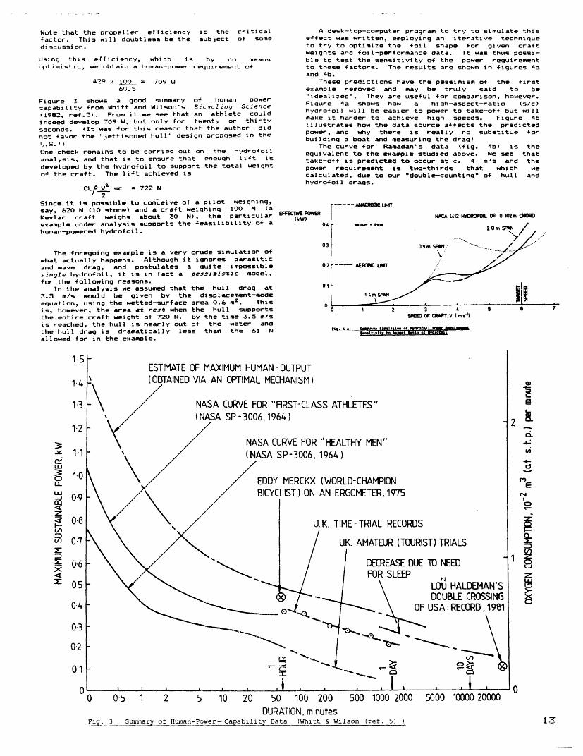
Note that the propeller efficiencyfactor. This will doubtless be thediscussion.
is the criticalsubject of some
Using this efficiency, which is by no meansoptimistic, we obtain a human-power requirement of
429 x 100 = 709 W60.5
Figure 3 shows a good summary of human powercapability from Whitt and Wilson's Bicycling Science(1982, ref.5). From it we see that an athlete couldindeed develop 709 W, but only for twenty or thirtyseconds. (It was for this reason that the author didnot favor the "jettisoned hull" design proposed in theU.S.')One check remains to be carried out on the hydrofoilanalysis, and that is to ensure that enough llft isdeveloped by the hydrofoil to support the total weightof the craft. The lift achieved is
CL V sc 722 N2
Since it is possible to conceive of a pilot weighing,say, 620 N (10 stone) and a craft weighing 100 N (aKevlar craft weighs about 30 N), the particularexample under analysis supports the feasilibility of ahuman-powered hydrofoil.
The foregoing example is a very crude simulation ofwhat actually happens. Although it ignores parasiticand wave drag, and postulates a quite impossiblesingle hydrofoil, it is in fact a pessimistic model,for the following reasons.
In the analysis we assumed that the hull drag at3.5 m/s would be given by the displacement-modeequation, using the wetted-surface area 0.6 m
2. This
is, however, the area at rest when the hull supportsthe entire craft weight of 720 N. By the time 3.5 m/sis reached, the hull is nearly out of the water andthe hull drag is dramatically less than the 61 Nallowed for in the example.
A desk-top-computer program to try to simulate thiseffect was written, employing an iterative techniqueto try to optimize the foil shape for given craftweights and foil-performance data. It was thus possi-ble to test the sensitivity of the power requirementto these factors. The results are shown in figures 4aand 4b.
These predictions have the pessimism of the firstexample removed and may be truly said to be"idealized". They are useful for comparison, however.Figure 4a shows how a high-aspect-ratio (s/c)hydrofoil will be easier to power to take-off but willmake it harder to achieve high speeds. Figure 4billustrates how the data source affects the predictedpower, and why there is really no substitue forbuilding a boat and measuring the drag'
The curve for Ramadan's data (fig. 4b) is theequivalent to the example studied above. We see thattake-off is predicted to occur at c. 4 m/s and thepower requirement is two-thirds that which wecalculated, due to our "double-counting" of hull andhydrofoil drags.
EFWCTNE PWWIkW)
01
09m SPN.
\'
---- AEROC LMT
SPEEl OF AFT. V Im's)
rESTIMATE OF MAXIMUM HUMAN-OUTPUT(OBTAINED VIA AN OPTIMAL MECHANISM)
NASA CURVE FOR "FIRST-CLI/ ((NASA SP-3006,1964)
ASS ATHLETES"
NASA CURVE FOR "HEALTHY MEN"
/
(NASA SP-3006, 1964)
EDDY MERCKX (WORLD-CHAMPIONBICYCLIST) ON AN ERGOMETER, 1975
U. K. TIME- TRIAL RECOIRDS
UK. AMATEUR (TOURIST) TRIAL
DECREASE DUE TO NEEDFOR SLEEP
LOU HA- amAL \ DOUBLE
a.~~~~-a
I I
A ___ l _~ i % --__ i I I
DURATION, minutesFig. 3 Summary of Human-Power- Capability Data (Whitt & Wilson (ref. 5) )
15
1.4
1-3
1.2
3cLU.J
Z
V)
Ln
xX:
1 -1
1-0
0-9
0.8
0.7
0-6
0-5
0-4
0.3
02
01
0
03
E
. kL
0
6
zLZCiO
A
S
LDEMAN'S! CROSSINGCORD, 1981
0 05 I 2 5 10 20 50 100 200 500 1000 2000 5000 10000 20000�_ �________ _ _ _____ · - .- - -- __
F
v
0-It- ~~~OF USA: RE,
I
I I . I I I- I -I~~~ ~~~ ~~~ ~~~ ~~~ ~~~~~~~~~~~~~~~~~~~~~~~~~~~~~~~~~~~~~~~~~~~~~~~~~~~~~~

HYDROFOIL
O!
..N[ P1ONRIkWI
0.4
0.3
02
0.1
,ll.&tifit *I~ lA _ ot-l~rexu s e
It is interesting to compare these performanceswith conventionally-hulled boats. Brewster (2) con-veniently did this, although postulating a slightlydifferent design of hydrofoil boat in his 19 79 thesis.His results are shown in figure 1. His analysis didnot allow for a combined shell/hydrofoil craft, but itcan be seen that the critical speed where thehydrofoil becomes superior to a shell is about 3.5m/s, while it out-performs even a submerged torpedo(N.B. Theodore Schmidt article) beyond 4.0 m/s!
I have tried to combine these two sets ofpredictions in figure 6 to show the whole amut ofpredicted power requirements from pessimistic toideal. We see that at best we are likely to be ableto achieve 6.0 m/s with an effective power of c. 300 W- well within human capability for extended periods -while at worst we will struggle to take off at thispower level, and soon encounter a "wall", makingspeeds of 5 m/s or above impossible.
It is almost a matter of faith as to which of theseanalyses you prefer. The author's experiences have"converted" him firmly to the optimistic end of thespectrum. The rest of this paper, on the morepractical aspects of this art, aims to preach thisgospel.
3. DEVELOPMENT OF A PRACTICAL CRAFT
Encouraged by the foregoing analysis and by JamesGrogano, who lent me his sailing/sculling hydrofoils,I designed and built a plywood kayak and fitted itwith an efficient transmission from pedals topropeller.
The craft was designed for 90% of its weight to besupported by the fully-submerged main fCoil. The smallvee-foil at the bows doubled as a rudder, and it tookthe remaining 10% load. The main foil was of solidaluminum, but could just be twisted elastically byhand. This proved to be ideal for controlling theroll of the boat - by far the most unstable mode. Thepilot was able to control the angle of attack of thefoil on both sides. Thus, if the boat rolled to port,he could increase the angle of attack on that side,generating more lift and righting the boat. In eightweeks of tests up to 20 mph the boat never capsized!
3.1 Towing Tests
Shoe-horned into this odd craft at the start of anevening's towing tests, the pilot could have beenforgiven for questioning his sanity. The lake ishighly exposed, and windsurfers and waterskiers do notlook as if they are going to make way for you even ifyou have their peers' permission. Your motor-boatdriver is very well-meaning and helpful but may notrealize just how precarious this strange boat feels.Your colleague in the motor-boat, whom you pressgangedinto taking an evening off by offering liquidrefreshment at the close, has the speed and tow-rope-force measurements to take as well as makingqualitative observations and instructing the motor-boat driver. Will he notice if you fall outs Itreally doesn't feel very stable...
Musing along these lines, I cheerfully gave the"OK" signal to the motor-boat, and we began to threadour way out to the calmer side of the clay-pit lake.Up til then we had tested the boat without foils tovalidate the hull-drag expression used in the theory.(It was accurate to within 5% up to 6.0 m/s.) Thetests so a,- with foils had been disastrous. Firstthe support mechanism had broken, then controll had
been such a problem that the whole system had to bere-designed. It was a much firmer and sturdier systemthat now challenged the waves.
The waves were getting ominously large. from sucha low level you need a swell of only a foot or so toobscure everything but Concorde from view. theobserver would try to adjust the tow-rope length sothat the front foil of the boat did not coincide witha trough in the motor-boat's wake, as this led to"crashes"; the small vee-foil, having no water tosupport it, crashing back into the foam.
Nevertheless, all seemed as stable as I knew itcould be. I signalled for the start of a test-runonce we arrived at the calmer, less-populated far sideof the lake. As 3 m/s (6.7 mph) was approached,control became trickier. Later we found this wasalmost entirely due to the towing mode - under humanpower all is more predictable. Spray from the motorboat, together with the new controls, made aninteresting ride. At this point, too, on all previousruns, something had broken and we had had to limp homedespondently.
This time, however, we carried on up to 3.5 m/s.All was well, if wet, but then I saw the front foildip down. This had happened before and meant we wereabout to "crash". Nothing happened, though. Throuqhthe spray I could see my colleague pointing excitedlytowards me and shouting at the motor-boat helmsman.Snatching a glance to one side I understood why. Thebow foil had not dipped as I had thought - the mainfoil had lifted. The hull was three inches clear ofthe water!
Then, of course, it did crash.The boat had taken off at a speed of 3.6 m/s with a
tow-rope force of 83 N. Hence an effective power of300 W was necessary to achieve take-off. Althoughthis is slightly higher than the computer predictions,it is of the same order, and within human-powercapability. Once foilborne, the tow-rope forcedropped, confirming the "power hump" shape of thepredictions (fig. 6).
These results were encouraging, and I went aheadand completed the fitting of the transmission and thepropeller in order to test the characteristics of thecraft in human-powered operation.
i
@I I
EXPERIMENTAL RESULTS OF CURRENT IONGTESTS
REWSTER'S COIfGRATION (BREWSTER 1979)12ORI T ESIGN, RMADAN'S ARFOL DATA(RAIADAN 192) 161IRPENT OESIGN, NACA AIRFL DATA (NACA |TN. 1945) !71
ONSET OFTAKE OFF
SPEED OF HYDROFOIL,
Fi. 6 IyJnUumh of Past and currentaor IQaent
V (m S(1)
60
Prediction of ydofoil
14
iA_
i ,
;J
fn

3.2 Human-powered Operation
Availability of lakes, personnel, and motor boathad severely restricted the possibilities for towingtests. Human-powered trials were less demanding. Twomen could handle the whole outing, which could becompleted within four hours.
Measurements, however, became more difficult totake. The speed had been measured electronically onthe motor boat in towing trials but this arrangementwas too cumbersome to consider attaching to the craftitself. We resorted to (distance/time) measurementstaken on shore, but accuracy suffered and instantane-ous readings became impossible. The thrust, which hadbeen measured by tow-rope tension, now had to beestimated from the propeller slip characteristic,which we assumed was a straight line (fig. 7).
The only points on the curve which we could checkwere the zero- and 100%-slip conditions. At 100%slip, we measured a maximum thrust of 258 N. Thisenabled us to calculate the effective thrust frommeasurement of propeller rpm and speed.
We then optimized the trim of the boat byconducting a series of trials with varying angles ofattack of the small bow fil. As expected, an optimumangle emerged (1-1/2'), which gave minimum drag at 3.5m/s.
We were then able to optimize the crucial operationof the main foil. It was hoped, at this point, thatthe pilot would be able to power up the boat to, say,2.5 m/s comfortably with the main foil at minimum-dragangle ( 1). Then with a burst of power he shouldtake the craft up to 3.5+ m/s and raise the angle ofattack to its maximum-lift condition (c. 70). Themomentum of the boat, plus ilot, would then help himover the "power hump" and into foilborne mode, atwhich point the foil could be returned to a low-dragangle (- 4) while power requirement would be withinaerobic capability.
This did not happen.For two weeks we tried various modifications and
methods of "take-off" control. There is no doubt thatthe ability of the pilot to control the boatconfidently and effectively is as important as purepower input. This was found with the GossamerAlbatros. However, inexperience at controlling thenew boat did not explain the disappointing performanceentirely.
The cyclist acting as pilot was fit and strong. Weknew from the color of his face that he was putting atleast 700 W into the transmission for short intervals.Yet we knew from the towing tests that the effectivepower from the propeller was less than 300 W (or itwould have taken off). Where was all that powergoing?
3.3 Analysis of Power Shortfall
Plainly the power was being lost in thetransmission somewhere and yet I had been uietlycongratulating myself on how efficiently and reliablyit had all appeared to work. Many People hadcommented on how well-made the propeller looked.
However, my suspicions lay with the propeller. Ilacked the facilities to test its efficiency tindercomparable conditions, so I had to work "backwards" tocalculate it. By confirming the efficiency of therest of the transmission, I would be able to deducethe propeller efficiency, since I knew approximatelythe overal efficiency.
To find the transmission efficiency, I simplypulled a pedal with a spring balance, with no load onthe propeller. The average force required to startthe propeller moving was 15.6 N. This implied atransmission loss, assuming the design pedal rotationof 120 rpm of:
15.6 2 (120/60) xForce Conversion
to radians/sec
0.165 = 2.3 WPedalradius
Assuming a power input of 750 W this represents aloss of only 4.3% compared with my ssumption of 11.1%(para. 2.2.1).
Now this is a very crude method of testingtransmission efficiency. It over-estimates the lossbecause static friction is greater than rollingfriction, but tinder-estimates it de to the absence 4thrust forces n the propeller shaft when measurementswere taken. However, it is unlikely that the ccuracyis worse than 100% and even if this were the ase. thedesign transmission loss is still greater than themeasured.
Assuming pessimistically, that the designtransmission loss of 11.1% is correct, we therefore
obtain an input to the propeller of:
750 W 100- ii.1 = 6' W100
We know that our output is in the range of 250 -300 W, since the boat had clearly almost taken off(indeed, the pilot was several times convinced that hehad, the boat had risen so much). We assume 275 W sopropeller efficiency becomes:
275/667 = 41%,
hopelessly below the design figure (given by themanufacturers) of 68%.
Other factors that reduced the craft's performancecan also be singled out. the design weight of craft-plus-pilot was 850 N, but after the strengthening ofthe main foil-control mechanism, the craft weight hadrisen to 369 N (83 lb). Even with the strictest diet,I could not have expected my pilot to slim to 500 N (8stone) and maintain his power output!
The craft was not only too heavy, but too big and,paradoxically, too stable. This was proved by thefact that no one fell out of it.
The NACA 4412 hydrofoils were solid and practical,btt a higher-lift section, like the Lisserman rofileused on many human-powered aircraft, could enabletake-off to take place at lower speeds and hence lowerpowers.
In short, there are many aspects of the r,,rrentprototype which can be improved, the outstandingopportunity being to increase propeller efficency.Already, with the help of Theodore Schmidt. I havemade progress in this area.
4. CRRENT WORV
After meeting at the recent Thamesead Festival inLondon, Theodore Schmidt (a fellow HPB bilder andconsulting engineer on kite systems) offered to make atwo-blade propeller to my basic requirements (pitch,diameter, and hub design) using ideas promulgated by'Gene Larrabee of MIT. In fapt, he made two suchpropellers, both of which were considerably lighterthan my aluminum three-blade propeller, and both ofhis out-performed mine. On a bitter evening on theThames at Putney we lacked the equipment to make anymore than rough estimates of the efficiencyimprovement, but we think even these first attemptsgive us 10-20% better efficiencies. Gene Larrabee'scomputer program "Helice" gives efficiencies as highas 92% for similar propellers and his 6ossaerAibatross propeller indeed achieved high efficienciesin the high 80s.
The second Oers Ark now being constructed has asimilar hull and lighter mainframe. Many hydrofoilsand propellers will be made for it in order to compareperfcrminces of different configurations. Althoughthe design is not yet finalized and I am open toideas, I am confident that it already incorporatesenough improvements to become the first practicalhuman-powered hydrofoil - if I have not already beenbeaten to it by Allen Abbott and Alec Brooks, andother rivals in the United States.
David Owers6 Leysfield RoadLondon W12 9JFEngland
David's new boat is being sponsored byand is being built at ritish erospace,UK.
REFERENCES
BOC Ltd.,Heybridge,
I. Hoerner, S. F. Fluid Dynamic rag, Chapter 11,pub. by the author, 1957.
2. Brewster, M. B., Design and Development of a an-Powered Hydrofoil. BSME Thesis, MIT, 1979.
3. Owers, D. J., Huxan-Pomered Transport - Design andDevelopment of a Hdrofoil Racing oat, M.Sc.Thesis, Cranfield, Sept. 1983.
4. Grogano, ., "A Sculling Hydrofoil Development",pp 275-279, in High-Speed Surface-CraftConference Papers, Brighton, England, June 1960.
5. Whitt, F. R., and Wilson, D. ., icyclingScience, 2nd Edition, The MIT Press, 1982.
6. Ramadan, M. M., easurements of the HydrodynamicForces on a NACA 4412 Foil, M.Eng. Thesis,University of Liverpool, March 1982.
7. NACA, 4412 Aerofoil Section TN, 1945.
8. Althus, D., Stuttgarter Profilkatalog, Inst:tutfur Aerodynamik nd Gas Dynamik der UIniversetat,Stuttgart, 1972.
15

HYDROFOILTABLE 1
* Ramadan measured the total drag coefficient C .Since the two-dimensional coefficient CDo has beenused in the calculations shown in this article, thefigures have been corrected, in the right-hand column,using the formula:
C D =CD + 2 C cs
where CL = lift coefficientc = chord length (m)s = span length (m)
Comparison of lift and drag coefficients for the NACA 4412 foil used.
9. Sakic, '., Approximate neteraznafton of thePropulsive Power of Sa'l! .'drofoi! Craft, Hiqh-Speed Surface Craft. March 1982.
10. Ptiermann. T. M.; Leehey, P.; and Stilwell, J. J.,
An Appra2sal of Hydrofoil-Supported Craft,American Society of Naval rchitects and Marine
Engineers Transactions, Vol 61. pp 242-264. 95..
Another of David Owers' HPB designs is pictured onpage 7.
COPYRIGHT aT 1985 The International Human Powered Vehicle Association, PostOffice Box 2068, Seal Beach, CA 90740 USA. All rights reserved. Reproductionof the whole or any part of the contents without written permission isprohibited. Second- and first-class postage paid at Huntington Beach, CA andadditional mailing locations. Cover design and title protected by U.S. andforeign trademark registrations. Editor: David Gordon Wilson, 15 Kennedy Drive,Cambridge, MA 02138. Subscription/membership information: Dues are US$15 percalender year for US mailing addresses. Addresses outside the USA, pleaseremit: US*17 for Canada and Mexico; all other countries US$20. Please make yourcheck or money order payable to the IHPVA. Send dues to: IHPVA, P 0 Box 2068,Seal Beach, CA 90740 USA.
IA
Source NACA TN 1945 Stuttgart Ramadan* Ramadan(corrected)*
C C CDo C C CL CDo CL
-2 0.0071 0.20 0.01610.105 - -
-1 0.0070 0.27 0.014 0.255 - -
O 0.0070 0.37 0.012 0350 0.021 0.30 0.017 0.30
1 0.0070 0.45 0.01C 0.430 0.022 0.37 0.017 037
2 0.0069 0.51 0.009 0-530 0.025 0.43 0.o18 0.43
3 0.0068 0.62 0.01C 0.620 0.030 0.49 0.020 0.49
4 0.0068 0.70 0.01C 0.710 0.037 0.56 0.025 0.56
5 0.0068 o.80 O.011 o .800 o .46 0.63 0.030 o.63
6 0.0071 0.87 0.012 0.800 0.055 0.70 0.036 0. 70
7 0.0075 0.95 0.01 0.950 0.064 0.76 0.041 0.76
8 0.0080 .99 0.020 1.030 - - - -


THE M I T NONRC H B s Ft rtt-Prst zm Wimu'r i n
t ie Kr e-mer Wor 1 d Sped Comp t i t 1i on
by John Langford and Mark Drela, MITAbstract
This paper provides an overview of the Monarch,MIT's human-powered aircraft that on May 11, 1984, wonfirst prize in the Kremer World Speed Competition.Designed and built by an all-volunteer team in 88 daysduring the summer of 1983, the Monarch made 29 flightsbefore it was dissassembled and stored for the winter.During the spring of 1984, a revised and improvedversion known as the Monarch B made 35 flights culmin-ating in the record flight. This paper details someof the design considerations and construction detailsbehind the Monarch, with particular attention to theaircraft's propulsion system and advanced avionics.
I. Introduction
In May of 1983, Britain's Royal AeronauticalSociety (RAeS) announced the third in its series ofhuman-powered aircraft (HPA) competitions. Known asthe Kremer World Speed Competition, this new contestoffered a £20,000 prize to the first entrant to fly a1500m closed course in less than 180 seconds (re-quiring a speed of roughly 20 mph). In a significantdeparture from the previous Figure-Eight and Cross-Channel prizes, the Speed Prize allowed the use ofenergy storage. During a ten-minute period before theflight the pilot(s) could store his own energy viawhatever means the contestants could devise. Therules also included provisions for officialobservation, minimum and maximum altitudes, aqualifying light, and follow-on prizes (L5000 each)each time the record is broken (1).
Upon announcement of the competition, a small groupof students at MIT (including the authors, Juan Cruz,and Steve Finberg) began to examine the feasibility ofwinning the prize. Three other HPAs had previouslybeen built at MIT. including BURDs I and II, designedto compete for the Figure-Eight Competition, and theChrysalis, flown some 350 times in 1Q79 as theprecursor to a hoped-for entry in the KremerCross-Channel Competition. Both of the authors hadworked on Chrysalis, and much of the technology wastransferred from that experience into the newestaircraft, known as the Monarch.
II. Design Considerations
At first glance the new competition appeared to bealmost too easy. Assuming a 10% increase in thecourse length (to 150m) to allow negotiation of thetriangular course, a lift-to-drag ratio of 20, and anaircraft weight (with pilot) of 950 N (210 lb), theenergy required to climb three meters and fly thecourse is approximately 81.2 kJ. Allowing for apropeller efficiency of 90%, approximately 90.5 kJwould thus be required at the propshaft. The power
available from the pilot depends on age, training, andmotivation, but Whitt and Wilson (2) indicate that 250W (.33 HP) could easily be obtained for the 13-minuteduration involved, and levels up to 400 W (.54 HP)might actually be available during the flight. With250 W provided for 9 minutes during the charge, theefficiency required from the energy-storage system wasonly about 30%. This efficiency could be achieved bya variety of systems, including electrical (bat-teries), mechanical (flywheel), and strain (rubber)energy storage.
Based on the encouraging initial calculations, weset out in late May to design and build an aircraftfor the competition. Primary design considerationsincluded the nderstandings that a) the project (bothfacilities and manpower) had to be completed beforethe fall 1983 academic semester began, and b) onlylimited funding would be available. Through July 1,1983, students on the project provided all thefunding. Thereafter, the Department of Aeronauticsprovided most of the funding. Total costs for theentire project ran to about $7300 (see (3) for a fulldiscussion of the design process).
These considerations, coupled with concerns aboutpotential competition from teams in California,Germany, and Japan, led to the selection of a"minimum" design that could set the record butprobably not break it, could be built quickly nearMIT, and would have minimum cost. The final designwas a tractor monoplane with an aft tail, one pilot,and wire-braced aluminum tube construction. Twoversions of the aircraft were eventually built: the"A" version that made 29 flights during the summer of1983, and a "B" version that made 35 flights duringthe spring of 1984 and set the speed record. The twoversions were very similar and used most of the sameparts, the B version differing by its use of recumbentpilot seating, the addition of ailerons, and the useof an actively-controlled variable-pitch propeller(see Figure 1).
III. Aerodyhamic Srfaces
The wing was a 18.75m- (62 ft-) span wire-bracedmonoplane. Since neither the project's schedule norbudget allowed the use of graphite-epoxy, the primarystructure was entirely 6061-T6 aluminum tithinq. Asingle 6.75-cm (2.5-in) o.d. spar located at the29%-chord point carried the lift loads. The spar had.89mm (.035 in) walls in the center panels, buttapered to .46mm (.018 in) at the tips ( the spar wastapered by chemical milling, which we performed in aone-day special operation). Designed for a yield loadof 2.0 g's, the outer 3.7m (12 ft) panel of the sparwas fully cantilevered. A single 1.09-mm- (.043-in)-diameter steel wire attached at the dihedral break
21

THE MIT ONARCH B
carried the main lift loads. A single wire from the
top mast was designed for 1.5-g downloads. The
trailing-edge wire was sized to carry the forward
loading encountered at high-lift conditions, while the
leading-edge wire and main lift wire together carried
aft bending loads. The wing was originally warped for
roll control, but 9%-chord ailerons were added to the
tip panels on the "B" version.
The airfoil was a modified Lissaman 7769, similar
to the airfoil used on the 6ossaver series of aircraft
and on ChrvSa!2s. Ribs were constructed from 2.0-
lb/ft foam, bought in blocks and sliced using amachine designed by ob Parks. Each rib had top and
bottom cap strips of qraphite-epoxy. To prrivent
debonding, each cap strip was secutred b a layer nf
.75 oz. fiberglass cloth. The leading edge was
sheeted with 4.7-mm (3/16-in)-thick foam. The ribs
were reinforced near the spar with .4-mm (1/64-in)
plywood. Special angled ribs at the panel joints took
both compression and covering loads. The wings werecovered with half-mil tensilized Mylar, donated byDuPont.
Construction of the all-flying rudder and stabili-=er were similar, except that these surfaces werefully cantilevered. The tail surfaces had 2.54-cm(1.0-in)-diameter spars and were covered withthird-mil Mylar.
IV. Fuselage
The fuselage was built of aluminum tubing, witheach joint machined to fit and then lashed with Kevlarroving. In the initial design the pilot was seatedvertically, but in the "B" version recumbent seatingwas used. The seat itself was Kevlar cloth stretchedover an aluminum frame. The pilot grasped a three-axis stick, with toggle switches on the stick formotor on/off and throttle control, and push switchesfor radio mike and manual control of prop pitch. Theaircraft had a main landing gear beneath the pilot anda small wheel beneath the nose. Both wheels were fulycastored and shock-absorbing. A brake was included on
the "B" version.
V. Propulsion System
After briefly considering flywheels (too complica-ted) and rubber (too heavy), we elected to develop anelectrical-energy-storage system. Tn our judqementthe relatively low efficiency (aboutt 33') was morethan offset by the low development time and cost. Thefinal system (shown in detail in Figure 1) consistedof: 1) standard bicycle cranks, driving a flexiblechain 2) a minimum-induced-loss tractor propeller,disconnected via a clutch during charging; ) a 62.2:1three-stage gearbox: 4) a 700-W DC motor (Geist type60/28) normally used for electric model aircraft; 5) apower controller; 6) a bank of 1.2 A-hr NiCad bat-teries; and 7) a servo, pushrod, and control logic to
vary the pitch of the propeller.The key concept in this system was the idea of
splitting the battery pack during charging. This
allowed us to use the flight motor as the generator,and to do so without changing the gearing betweencharging and flying (the conversion could be accom-plished in less than 10 seconds). We-traded mechani-cal complexity for electronic complexity: a keyelement in the system was the power controller.Designed and built by Steve Finberg, the controller
performed a variety of functions, including: 1)
splitting the battery pack, automatically cyclingbetween two subpacks every ten seconds duringcharging: 2) providing visual confirmation of charge
cycling via LEDs:; 3) providing a direct ckurrent
between the batteries and the motor the pilot turned
the motor on and off via a relay, and the amperale
readings were taken via a Hall-Effect device, without
the losses of a shi:nt); 4) use of a current-sensinq
system to act as a no-loss diode: and 5) sensing
battery-pack voltage and providing an audible low-
voltaqe alarm.
.u Performance of the propulsion system is illustrated
in Figure 2. Curves of motor performance (power pro-duced versus rpm and voltage) are plotted along withpropeller performance (power absorbed versus proppitch and rpm) for a given flight speed. If the pilotproduces no power, the system will operate at the
intersection of the appropriate voltage and prop-pitch
curves. Once the pilot pedals faster than the corres-ponding rpm, he adds power to the system. At thecontest operation point, the pilot producedapproximately 75% of the total power.
Initially the voltage and the prop pitch were
variable only on the ground. This produced seri;ous
problems during the initial flight program: when tinepilot increased his output power, only a fraction was
delivered to the propeller while the rest merelyunloaded the motor. This was solved on the "B"version by the introduction of a variable-pitchpropeller. By coupling the current-sensing feature ofthe power controller to additional electronic logic,an active-control system was developed that wouldmaintain a selected motor current at all times bymaking appropriate adjustments to the propeller pitch.Not only did this ncouple the motor's output from thepilot's, but it provided a convenient throttle and
thins a means of rationing the electrical energy for
optimum use throughout the flight. The pilot wasprovided with a two-position electronic "throttle"providing him with "climb" and "cruise" powersettings, and the exact current associated with eachthrottle setting was adjusted between flights throughpotentiometers.
VI. Flight Program
Monarch made its first flight on August 14, 1983with Rick Sheppe at the controls. A certified flightinstructor, Rick was not a trained athlete and wasnever intended to be the pilot for the record attempt.Unfortunately, the pilot/athlete who had been trainingcrashed the aircraft on his second flight, on August19. The aircraft was repaired and flying again bySeptember 2 with a third pilot, Frank Scarabino.Between September 2 and September 23, 1983, Scarabinomade 25 flights, including several attempts withobservers to fly the qualifying course. Pressuresfrom MIT's fall academic semester, however, led to acurtailment of activity, and after the MacCreadyBionic at team claimed the record on September 25(see Part VII). the Monarch was disassembled andstored for the winter.
The spring 1984 test program included 35 flights,all by Scarabino. The first flight of the "B" versionwas made on April 3, 1984. On April 30 the onarchcompleted its qualifying flight, and on May 5
Scarabino missed the Kremer prize by .43 seconds. OnMay 11, 198, Scarabino flew the course in 00:02:49.7,
claiming the speed record and, as noted by New
scientst, "adding a new name to the rolls of the
Kremer Prizes". At the end of the charge period thedoor zipper had jammed, so Scarabino crossed thestarting line 00:10:05 after commencement of theenergy storage. The five seconds were added to theflight time, and on July 20 the Man Powered AircraftGroup of the RAeS certified the record at 00:02:55.Following review and approval by the RAeS PrizeCommittee, the Governing Council of the RAeS voted onSeptember 27, 1984, to declare the onarch's flight
official and to award the 20,000 first prize to MIT.
VII. Competitors
The race for the Kremer World Speed record was theclosest human-powered-aircraft competition yet. Ateam under the direction of Paul MacCready (winner ofthe first two Kremer prizes) built an entry known as
the Bionic Bat. The Bat filed a claim on the Speed
Prize in September 1983, but the claim was resected bythe RAeS in November, 1983, on the grounds that therules concerning the enerqv-storage system had beenviolated. MacCready renewed his attempts on therecord in January, 1984, and made continued design
changes to the aircraft throughout the first half of
24
WnUca-r
w00oa.
100 . ..--a: :::,,......:','"' ..'I '', : :' : :'..... ... ... . .............. ...........
;. .TAL D -:: .... . ..
ii-- " -
... - -. .. .. .L .. . . . .. . .. i. ....500 -: .
5 982
RPM PEDALS
isUVB l
85 90 95 1G00
Figure 2 - Operatzng sap of the Monarch propulsion
svtem fr a f zht speed of 22 mph. o] d
curves represent motor performance dotted lines,prop performance.
It D.


.1;
B~O
a
si~ ~~~
WI
o a
C-
/ El~~~~~~~~~~l· s 1
/'I~~~~~~~~~~~~~Cit~~~~~~~~~~~5Q~~~~~~~ r~~r
El ~ ~ ~ ~ ~ ~ t
9*-· ~ a
~~ *'*191
24


![Jianyi Zhang Andrew Gordon Wilson arXiv:1902.03932v2 [cs.LG] … · 2020. 5. 13. · Andrew Gordon Wilson New York University andrewgw@cims.nyu.edu ABSTRACT The posteriors over neural](https://img.pdfslide.net/doc/110x75/5ff4ecea7fe9606d0f2a240f/jianyi-zhang-andrew-gordon-wilson-arxiv190203932v2-cslg-2020-5-13-andrew.jpg)