Embed Size (px)
Citation preview
April 2016
3.2.1.
DAYLIGHTING AND ELECTRIC LIGHTING RETROFIT SOLUTIONS
A SOURCE BOOK OF IEA SHC TASK 50 ‘ADVANCED LIGHTING FOR RETROFITTING BUILDINGS’

Universitätsverlag der TU Berlin
DAYLIGHTING AND ELECTRIC LIGHTING RETROFIT SOLUTIONS
Martine Knoop (eds.)
Bibliographic information published by the Deutsche Nationalbibliothek The Deutsche Nationalbibliothek lists this publication in the Deutsche Nationalbibliograie; detailed bibliographic data are available in the Internet at http://dnb.dnb.de.
Universitätsverlag der TU Berlin, 2016
http:// verlag.tu-berlin.de Fasanenstr. 88, 10623 Berlin Tel.: +49 (0)30 314 76131 / Fax: -76133 E-Mail: [email protected]
This work is protected by copyright. © 2016 International Energy Agency (IEA) Solar Heating and Cooling Pro gramme.
ISBN 978-3-7983-2836-5 (online)
Online published on the institutional Repository of the Technische Universität Berlin: DOI 10.14279/depositonce-5162 http://dx.doi.org/10.14279/depositonce-5162
Daylighting and Electric Lighting Retroit Solutions, a source book of IEA SHC Task 50 ‘Advanced Lighting for Retroit Buildings’ by Martine Knoop with Berat Aktuna, Bruno Bueno, Stanislav Darula, Arnaud Deneyer, Aicha Diakite, Peter Fuhrmann, David Geisler-Moroder, Carolin Hubschneider, Kjeld Johnsen, Andre Kostro, Marta Malikova, Barbara Matusiak, Patrick Prella, Wilfried Pohl, Luo Tao and Eino Tetri.
Layout: Aicha Diakite, Martine Knoop
This source book is the outcome of IEA SHC Task 50, Subtask B ‘Daylighting and Electric Light-ing Solutions’. The authors thank their respective funding agencies for supporting their work:
» bmvit - Bundesministerium für Verkehr, Innovation und Technologie and FFG - Die Österreichische Forschungsförderungsgesellschaft, Austria
» Bundesministerium für Wirtschaft und Technologie, Germany » China Academy of Building Research, China » Danish Energy Agency, Energy Technology Development and Demonstration
Program, Denmark » Finnish RYM Indoor Environment Program, Finland » Research Council of Norway, Norway » Service Public de Wallonie, DGO4, Belgium » Slovak Academy of Sciences - international scientiic cooperation scheme
(MVTS – medzinárodná vedecko-technická spolupráca), Slovakia
Legal notice: Neither the International Energy Agency, nor any of their employees, nor any of the IEA Task 50 participants makes any warranty, express or implied, or assumes legal liab-ility or responsibility for the accuracy, completeness or usefulness of the information or the products or services referred to in this source book and shall not be liable for any losses or damage that may result from use of it as a consequence of any inaccuracies in, or any omis-sions from, the information which it may contain.
DAYLIGHTING AND ELECTRIC LIGHTING RETROFIT SOLUTIONS
PREFACE
Lighting accounts for approximately 19 % (~3000 TWh) of the global electric energy con-sumption. Without essential changes in policies, markets and practical implementations it is expected to continuously grow despite signiicant and rapid technical improvements like solid-state lighting, new façade and light management techniques.
With a small volume of new buildings, major lighting energy savings can only be realized by retroitting the existing building stock. Many countries face the same situation: The majority of the lighting installations are considered to be out of date (older than 25 years). Compared to existing installations, new solutions allow a signiicant increase in eiciency – easily by a factor of three or more – very often going along with highly interesting payback times. How-ever, lighting refurbishments are still lagging behind compared to what is economically and technically possible and feasible.
IEA SHC Task 50: Advanced Lighting Solutions for Retroitting Buildings” therefore pursues the goal to accelerate retroitting of daylighting and electric lighting solutions in the non‐resid-ential sector using cost‐efective, best practice approaches.
This includes the following activities: » Develop a sound overview of the lighting retroit market » Trigger discussion, initiate revision and enhancement of local and national regulations,
certiications and loan programs » Increase robustness of daylight and electric lighting retroit approaches technically, eco-
logically and economically » Increase understanding of lighting retroit processes by providing adequate tools for dif-
ferent stakeholders » Demonstrate state-of-the-art lighting retroits » Develop as a joint activity an electronic interactive source book (“Lighting Retroit Ad-
viser”) including design inspirations, design advice, decision tools and design tools
To achieve this goal, the work plan of IEA-Task 50 is organized according to the following four main subtasks, which are interconnected by a joint working group:Subtask A: Market and PoliciesSubtask B: Daylighting and Electric Lighting SolutionsSubtask C: Methods and ToolsSubtask D: Case StudiesJoint Working Group (JWG): Lighting Retroit Adviser
Preface i

The Solar Heating and Cooling Programme was founded in 1977 as one of the irst multilat-eral technology initiatives (“Implementing Agreements”) of the International Energy Agency. Its mission is “to enhance collective knowledge and application of solar heating and cooling through international collaboration to reach the goal set in the vision of solar thermal energy meeting 50 % of low temperature heating and cooling demand by 2050.
The member countries of the Programme collaborate on projects (referred to as “Tasks”) in the ield of research, development, demonstration (RD&D), and test methods for solar thermal energy and solar buildings.
A total of 52 such projects have been initiated to-date, 39 of which have been completed. Research topics include: » Solar Space Heating and Water Heating (Tasks 14, 19, 26, 44) » Solar Cooling (Tasks 25, 38, 48) » Solar Heat or Industrial or Agricultural Processes (Tasks 29, 33, 49) » Solar District Heating (Tasks 7, 45) » Solar Buildings/Architecture/Urban Planning (Tasks 8, 11, 12, 13, 20, 22, 23, 28, 37, 40, 41,
47, 51, 52) » Solar Thermal & PV (Tasks 16, 35) » Daylighting/Lighting (Tasks 21, 31, 50) » Materials/Components for Solar Heating and Cooling (Tasks 2, 3, 6, 10, 18, 27, 39) » Standards, Certiication, and Test Methods (Tasks 14, 24, 34, 43) » Resource Assessment (Tasks 1, 4, 5, 9, 17, 36, 46) » Storage of Solar Heat (Tasks 7, 32, 42)
In addition to the project work, there are special activities: » SHC International Conference on Solar Heating and Cooling for Buildings and Industry » Solar Heat Worldwide – annual statistics publication » Memorandum of Understanding with solar thermal trade organizations » Workshops and conferences
Country Members
Australia Denmark France Portugal Sweden
Austria European Italy Singapore United States
Belgium Commission Mexico South Africa
China Germany Netherlands Switzerland
Canada Finland Norway Spain
Sponsor Members
ECI ECREEE RCREEE
Further information: For up to date information on the IEA SHC work, including many free publications, please visit www.iea-shc.org.
NOTICE: The Solar Heating and Cooling Programme, also known as the Programme to De-velop and Test Solar Heating and Cooling Systems, functions within a framework created by the International Energy Agency (IEA). Views, indings and publications of the Solar Heating and Cooling Programme do not necessarily represent the views or policies of the IEA Secret-ariat or of all its individual member countries.
IEA SOLAR HEATING AND COOLING PROGRAMME
IEA Solar Heating and Cooling Programmeii
EXECUTIVE SUMMARY
Due to the world’s growing population and the increasing electrical energy demand in emer-ging economies, an increase of electric energy use for lighting is expected. Energy eicient lighting is said to be one of the most cost-efective approaches to save energy and reduce C02 emissions. In order to stimulate the application of lighting retroits of good quality, IEA Task 50, Subtask B “Daylighting and Electric Lighting solutions” has looked into the assessment of existing and new technical retroit solutions in the ield of façade and daylighting technology, electric lighting and lighting controls.
The document provides information for those involved in the development of retroit products or involved in the decision making process of a retroit project, such as buildings owners, authorities, designers and consultants, as well as the lighting and façade industry. In contrast to other retroit guides, this source book addresses both electric lighting solu-tions and daylighting solutions, and ofers a method to compare these retroit solutions on a common basis, including a wide range of quality criteria of cost-related and lighting quality aspects.
Simple retroits, such as replacing a lamp or adding interior blinds, are widely accepted, often applied because of their low initial costs or short payback periods. The work presented in this report aims at promoting state-of-the-art and new lighting retroit approaches that might cost more but ofer a further reduction of energy consumption while improving lighting quality to a greater extend. A higher lighting quality can increase health, self-assessed per-formance, and lead to a higher job satisfaction and thus productivity in work environment. In this, the use of daylight is speciically promoted, as an optimized daylighting design, or the use of innovative daylighting systems are rarely taken into consideration in the retroit pro-cesses of buildings, and daylight utilization will both reduce energy consumption for electric lighting as well as increase user well-being.
In order to assess retroit technologies on their ability to save electrical energy, to increase lighting quality and to afect operational costs, a Catalogue of Criteria was developed. It con-sists of a large number of quality measures that can be applied to evaluate the performance of lighting controls, electric lighting retroits and daylighting retroits. The selection of quality measures can be used to describe the performance of lighting retroit solutions, qualitatively and to some degree quantitatively. The Catalogue of Criteria allows to make a sensible, irst, decision for a (selection of ) lighting retroit solution(s). In this source book, the Catalogue of Criteria is used to evaluate the performance of a selection of retroit solutions. Product fam-ilies of lighting retroit technologies are evaluated, and an overall performance assessment for each type of retroit solution is given. The actual performance of a speciic product in that retroit family needs to be established within the context of a project.
The assessment of selected technologies showed that » next to replacing a lamp or adding interior blinds, a task - ambient lighting concept, oc-
cupancy sensing, personal control in daylit spaces, daylight responsive lighting control through switching, time scheduling, wireless controls (occupancy and daylight respons-ive), and replacing an magnetic ballast with an electronic ballast, can be economical solu-tions that reduce energy consumption for electric lighting.
» most electric lighting retroit solutions ofer high energy savings but do not necessarily improve lighting quality.
» daylighting retroit solutions generally have higher investment costs. The energy savings potential ofered by these retroits can be (partially) harvested when applying a daylight responsive lighting control system or ofering the user personal control over the electric lighting.
Executive Summary iii
» non-economic beneits, or indirect economic beneits, such as the increase of lighting quality, can be achieved with daylighting retroit solutions that enhance daylight provi-sion in a room, and electric lighting and control solutions that might require a redesign of the lighting installation.
While the choice for a lighting retroits solution nowadays is mainly based on cost and energy reduction, a retroit solution can afect lighting quality and thermal loads as well, which has an indirect economical or environmental impact. This should be considered in the selection of the appropriate lighting retroit solution. The greater part of electric lighting retroit solu-tions focuses on reduced price and increased eicacy to achieve short payback periods; high end electric lighting solutions, as well as the majority of lighting controls and daylighting solutions are developed and applied to increase user comfort and lighting quality.
Executive Summaryiv
CONTENTS
Contents
Preface i
IEA Solar Heating and Cooling Programme ii
Executive summary iii
1. Introduction 1
1.1 Objective and scope of this source book 2
1.2 How to use this book 3
2. Rating and comparison of lighting retroit technologies 4
2.1 Catalogue of Criteria 4
2.1.1 Baseline 5
2.1.2 Quality measures: Energy eiciency 6
2.1.3 Quality measures: Thermal considerations 8
2.1.4 Quality measures: Lighting quality 9
2.1.5 Quality measures: Maintenance 10
2.1.6 Quality measures: Costs 11
2.1.7 Use of the Catalogue of Criteria 11
2.1.8 Drawbacks of the Catalogue of Criteria 12
2.2 Comparison of retroit solutions 12
2.3 Representation of product performance 13
3. Overview of systems 14
3.1 Building interior 16
3.2 Daylighting systems 18
3.2.1 Skylights 21
3.2.2 Acrylic skylights 22
3.2.3 Light tubes 23
3.2.4 Lamellae heliostats 24
3.2.5 Translucent skylight systems 25
3.2.6 Micro sunshading louvres 26
3.2.7 Enlargement of window area 27
3.2.8 Light shelves 28
3.2.9 Louvres 29
3.2.10 Shutters 32
3.2.11 Electrochromic glazing 33
3.2.12 Micro lamellae 35
3.2.13 Microstructured glazing 36
Contents
3.2.14 Prismatic elements 37
3.2.15 Laser cut panels 38
3.2.16 Sun protection ilms 39
3.2.17 Blinds 40
3.2.18 Redirecting blinds 42
3.2.19 Stainless steel roller shutters 44
3.2.20 Sunscreens 45
3.3 Electric lighting systems 46
3.3.1 Task – ambient lighting 48
3.3.2 Algorithmic lighting 49
3.3.3 Virtual windows 50
3.3.4 Demand driven lighting controls 51
3.3.5 Daylight responsive lighting control, daylight harvesting 52
3.3.6 LED luminaire replacements 54
3.3.7 LED retroits for CFL downlights 55
3.3.8 Personal control 56
3.3.9 Occupancy sensing 57
3.3.10 Time scheduling 58
3.3.11 Wireless lighting controls 59
3.3.12 Electronic ballasts (HF+) 60
3.3.13 Fluorescent lamps (T5, CFL) 61
3.3.14 LED replacements for halogen / incandescent lamps 62
3.3.15 LED T8 replacement lamps 63
4. Performance assessment of selected solutions 65
5. Conclusions and outlook 73
6. References 75
7. Copyrights 82
Appendix A: List of Criteria 87
1.INTRODUCTION
Introduction 1
Lighting accounts for approximately 19% of the global electric energy consumption (IEA 2006). Depending on the application, an installed Lighting Power Density (LPD) of 10 to 30 W/m², on average a yearly energy consumption of 20 – 25 kWh/m²y , can typically be found in commercial buildings. Modern lighting solutions can reduce the LPD to 5 – 15 W/m², with even larger savings on the annual energy consumption when appropriate controls are be-ing used (5 - 9 kWh/m²yr, Dubois and Blomsterberg 2011). Nonetheless, due to the world’s growing population and the increasing electrical energy demand in emerging economies, a further increase of 40% of electric energy use for lighting is expected in 2030 (Dubios et al. 2014, based on IEA 2006). The global ‘Carbon abatement opportunities map’ of McKinsey and Vattenfall Institute of Economic Research (McKinsey 2008) indicates that the use of energy ‐ eicient lighting is one of the most cost-efective approaches to reduce C02 emissions, espe-cially for a simple retroit, the switch from incandescent to LED light sources (McKinsey 2010).
Simple retroits, such as replacing a lamp or adding interior blinds, are widely accepted, often applied because of their low initial costs or short payback periods. In practice, an optimized daylighting design, or the use of innovative daylighting systems or lighting control systems are rarely taken into consideration in the retroit processes of buildings. The work presented in this report aims at promoting state-of-the-art and new lighting retroit approaches that might cost more but ofer a (further) reduction of energy consumption while improving light-ing quality to a greater extend.
This source book summarizes the work done within Subtask B “Daylighting and Electric Light-ing Solutions” of IEA Task 50 “Advanced Lighting Solutions for Retroitting Buildings”. Other projects, such as IEA Task 21 “Daylight in Buildings”, IEA Task 31 “Daylighting Buildings in the 21st Century”, IEA ECBCS Annex 45 ”Energy-Eicient Future Electric Lighting for Buildings” and Task 47 “Solar Renovation of Non-Residential Buildings” have dealt with related topics. From these projects it was possible to summarize the key steps for energy eicient lighting solutions: 1. Use natural lighting indoors as much as possible, and consider both lighting and thermal
impact in the overall energy consumption.2. For times with insuicient daylighting, use eicient electric (lighting) components: lamps,
ballasts and luminaires, in an appropriate lighting design. The design should address that light is applied where it is needed.
3. Use lighting controls, especially those that take advantage of available daylight. Lighting controls should be applied to ofer light when it is needed.
4. Develop an appropriate maintenance regime; keep luminaires and lamps clean.
The main reasons for a lighting retroit are to achieve energy savings or a green building cer-tiication, to reduce cost or maintenance, or to increase lighting quality or user satisfaction.
1
Introduction2
The majority of refurbishment, retroitting and renovation activities is nonetheless typically related to reduction of energy use (Gohardani and Björk 2012). This document looks into a lighting retroits that can be applied for further reduction of energy consumption while im-proving lighting quality to a greater extend. Even though no precise deinition of lighting quality exists (CIE 1998), it is typically related to the degree of which the lighting meets the needs of the occupants of the space. Research showed that lighting with a higher quality can positively afect job satisfaction, organizational commitment, health and self-assessed performance (Veitch et al. 2010).
The use of daylight should be promoted. From an environmental point of view (in contra-diction to a pure economical one), daylight utilization is of importance. Any electric lighting solution needs electricity often generated by non-renewable source, such as fossil or nuclear fuels. Even though the LPD will be reduced signiicantly by the implementation of LED light-ing solutions, and the absolute energy savings to be reached by using controls is diminish-ing, from an environmental point of view, any reduction of energy consumption is sensible. Although payback periods for daylight responsive controls might increase at irst when LED systems are widely applied as retroit solutions, it is expected that new technology will result in a reduction of costs for sensors and controls in the near future, which might afect the payback period. Additionally to that, besides ofering a reduction of energy consumption for the electric lighting installation, daylight utilization also likely increases user well-being. It is generally acknowledged that occupants prefer daylight to electric lighting. Daylight can positively afect stress and mood, and support visual and non-visual responses (e.g. Boyce et al. 2003, Veitch and Galasiu 2012, Strong 2012 and section 3.2).
OBJECTIVE AND SCOPE OF THIS SOURCE BOOK
This document aims at promoting state-of-the-art and new retroit approaches, considering both electric lighting and daylighting solutions.
» In Chapter 2 a Catalogue of Criteria is presented, that can be used to rate and compare various retroit technologies on a holistic basis. It includes the description of a baseline as well as 30 quality criteria.
» Chapter 3 includes general descriptions of retroit technologies. These technologies are assessed by means of the Catalogue of Criteria in Chapter 4, giving an indication of the performance of each technology in a quantitative manner.
» Conclusions and an outlook can be found in Chapter 5
1.1
Readers seeking information on how to compare retroit technologies, especially those not included in this source book, should read Chapter 2.
For those interested in the variety of lighting retroit technologies, a presentation of selected types of retroit solutions can be found in Chapter 3, including a description, the advantages and disadvantages of the technology, pictures and references to literature of interest. The description is representative for the majority of products within this technology family, but does not represent the performance of each product available for this technology
An overview of the performance of these selected technologies can be found in Chapter 4. Note that this chapter looks into daylighting and electric lighting retroit solutions on a product level only. It gives an overview of the potential of products when installed, calibrated and commissioned properly. It allows to make a sensible, irst, decision for a (selection of ) lighting retroit solution(s). The ultimate decision for a solution, based on the costs, the es-timated energy savings and the lighting quality in an application, should be determined with knowledge about that speciic application. For this, please refer to » the tools as proposed by IEA Task 50 Subtask C “Methods and Tools”, » the case studies evaluated within IEA Task 50 Subtask D, or » the “Lighting Retroit Adviser” of the Joint Working Group of IEA Task 50.
Application relevant information can also be found in public guidelines, such as the Ad-vanced Energy Retroit Guides of the US Oice of Energy Eiciency & Renewable Energy (EERE 2011, 2013, www.energy.gov). Barriers for renovation and retroit activities are speciically addressed in the material provided by Subtask A of IEA Task 50.
A large number of pictures used in this source book have copyrights. These pictures are marked with ©. Details to copyrights can be found in chapter 7 on page 82.
Introduction 3
1.2HOW TO USE THIS BOOK
2.
One hurdle to overcome when considering alternative solutions in a retroit project is the lack of an appropriate approach to compare solutions on a common basis. Previous projects that have considered both cost-related and lighting quality aspects, focused either on the evalu-ation of daylighting solutions or on the assessment of electric lighting solutions. The quality of (parts) of an electric lighting solution is often described with features such as light output or lifetime. However, the quality criteria used for electric lighting are usually not applicable or not suicient to describe the quality of daylighting solution or the efect on people. Res-ulting, to properly evaluate the impact of lighting retroit decisions, a wide range of quality criteria should be considered, preferably applicable to both electric lighting and daylighting solutions. This chapter ofers a list of quality measures to evaluate the efectiveness of lighting retroit solutions to reduce energy consumption and running costs as well as improve light-ing quality. This selection of quality measures, the so called Catalogue of Criteria, can be used to describe the performance of lighting retroit solutions, qualitatively and to some degree quantitatively.
CATALOGUE OF CRITERIA
In order to evaluate a large variety of daylighting and electric lighting retroit solutions, on an equal and holistic basis, a Catalogue of Criteria was deined, to allow for a quantitative comparison of retroit possibilities. The quality measures included in the Catalogue of Criteria were taken from literature, standards, and experience (e.g. Ruck et al. 2000, CEN 2005, CEN 2007, CEN 2011) and consider: » aspects from an ecological and economic point of view, such as those related to acquisi-
tion of the system, energy consumption, and maintenance » user requirements, such as psychological and physiological, visual and non-visual, human
needs » impact of the lighting retroit on the overall retroit process » thermal beneits of daylighting systems » geographical and climatological applicability.
Focusing on product related aspects only and rejecting all application relevant quality criteria from the approximately 100 established measures, the Catalogue of Criteria contains over 30 quality measures that primarily focus on the following reasons to retroit: » reduce energy consumption » increase the lighting quality » reduce the operational costs.
The Catalogue of Criteria also includes aspects related to possible drawbacks of the retroit solution, such as the impact of the retroit process, the duration and costs of the lighting retroit, as well as thermal characteristics that do not afect the potential savings for electrical lighting, but could afect the overall building energy consumption.
By allowing an evaluation of both daylighting and electric lighting solutions on the main features, potential energy savings for electric lighting, lighting quality, thermal aspects and costs, a comparison of distinct diferent retroit approaches on a common basis is feasible, see chapter 4.
RATING AND COMPARISON OF RETROFIT TECHNOLOGIES
2.1
Rating and Comparison of Retroit Technologies4
2.1.1
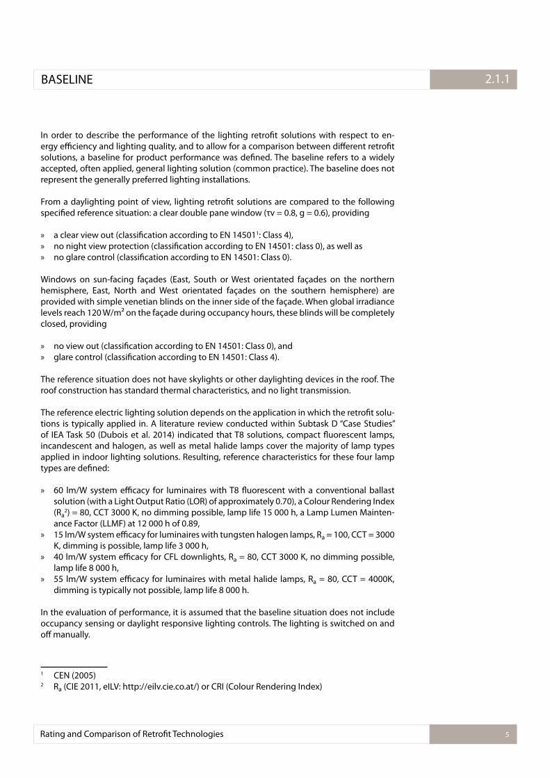
In order to describe the performance of the lighting retroit solutions with respect to en-ergy eiciency and lighting quality, and to allow for a comparison between diferent retroit solutions, a baseline for product performance was deined. The baseline refers to a widely accepted, often applied, general lighting solution (common practice). The baseline does not represent the generally preferred lighting installations.
From a daylighting point of view, lighting retroit solutions are compared to the following speciied reference situation: a clear double pane window (τv = 0.8, g = 0.6), providing
» a clear view out (classiication according to EN 145011: Class 4), » no night view protection (classiication according to EN 14501: class 0), as well as » no glare control (classiication according to EN 14501: Class 0).
Windows on sun-facing façades (East, South or West orientated façades on the northern hemisphere, East, North and West orientated façades on the southern hemisphere) are provided with simple venetian blinds on the inner side of the façade. When global irradiance levels reach 120 W/m² on the façade during occupancy hours, these blinds will be completely closed, providing
» no view out (classiication according to EN 14501: Class 0), and » glare control (classiication according to EN 14501: Class 4).
The reference situation does not have skylights or other daylighting devices in the roof. The roof construction has standard thermal characteristics, and no light transmission.
The reference electric lighting solution depends on the application in which the retroit solu-tions is typically applied in. A literature review conducted within Subtask D “Case Studies” of IEA Task 50 (Dubois et al. 2014) indicated that T8 solutions, compact luorescent lamps, incandescent and halogen, as well as metal halide lamps cover the majority of lamp types applied in indoor lighting solutions. Resulting, reference characteristics for these four lamp types are deined:
» 60 lm/W system eicacy for luminaires with T8 luorescent with a conventional ballast solution (with a Light Output Ratio (LOR) of approximately 0.70), a Colour Rendering Index (Ra
2) = 80, CCT 3000 K, no dimming possible, lamp life 15 000 h, a Lamp Lumen Mainten-ance Factor (LLMF) at 12 000 h of 0.89,
» 15 lm/W system eicacy for luminaires with tungsten halogen lamps, Ra = 100, CCT = 3000 K, dimming is possible, lamp life 3 000 h,
» 40 lm/W system eicacy for CFL downlights, Ra = 80, CCT 3000 K, no dimming possible, lamp life 8 000 h,
» 55 lm/W system eicacy for luminaires with metal halide lamps, Ra = 80, CCT = 4000K, dimming is typically not possible, lamp life 8 000 h.
In the evaluation of performance, it is assumed that the baseline situation does not include occupancy sensing or daylight responsive lighting controls. The lighting is switched on and of manually.
1 CEN (2005)2 Ra
(CIE 2011, eILV: http://eilv.cie.co.at/) or CRI (Colour Rendering Index)
BASELINE
Rating and Comparison of Retroit Technologies 5
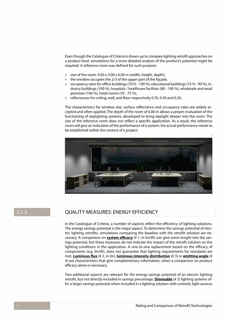
Even though the Catalogue of Criteria is drawn up to compare lighting retroit approaches on a product level, simulations for a more detailed analysis of the product’s potential might be required. A reference room was deined for such purpose:
» size of the room: 9.00 x 3.00 x 6.00 m (width, height, depth), » the window occupies the 2/3 of the upper part of the façade, » occupancy rates for oice buildings (70 % - 100 %), educational buildings (75 % - 90 %), in-
dustry buildings (100 %), hospitals / healthcare facilities (80 - 100 %), wholesale and retail premises (100 %), hotel rooms (70 - 75 %),
» relectances for ceiling, wall, and loor respectively 0.70, 0.50 and 0.20.
The characteristics for window size, surface relectance and occupancy rates are widely ac-cepted and often applied. The depth of the room of 6.00 m allows a proper evaluation of the functioning of daylighting systems, developed to bring daylight deeper into the room. The size of the reference room does not relect a speciic application. As a result, the reference room will give an indication of the performance of a system; the actual performance needs to be established within the context of a project.
QUALITY MEASURES: ENERGY EFFICIENCY
In the Catalogue of Criteria, a number of aspects relect the eiciency of lighting solutions. The energy savings potential is the major aspect. To determine the savings potential of elec-tric lighting retroits, simulations comparing the baseline with the retroit solution are ne-cessary. A comparison on system eicacy (# 1, in lm/W) can give some insight into the sav-ings potential, but these measures do not indicate the impact of the retroit solution on the lighting conditions in the application. A one-to-one replacement based on the eicacy of components (e.g. lm/W), does not guarantee that lighting requirements for standards are met. Luminous lux (# 2, in lm), luminous intensity distribution (# 3) or emitting angle (# 4) are characteristics that give complementary information, when a comparison on product eicacy alone is necessary.
Two additional aspects are relevant for the energy savings potential of an electric lighting retroit, but not directly included in savings percentage. Dimmable (# 5) lighting systems of-fer a larger savings potential when included in a lighting solution with controls; light sources
2
2.1.2
Rating and Comparison of Retroit Technologies6
with a low power factor (# 6) are ineicient, even though this is not relected in the metered use of power.
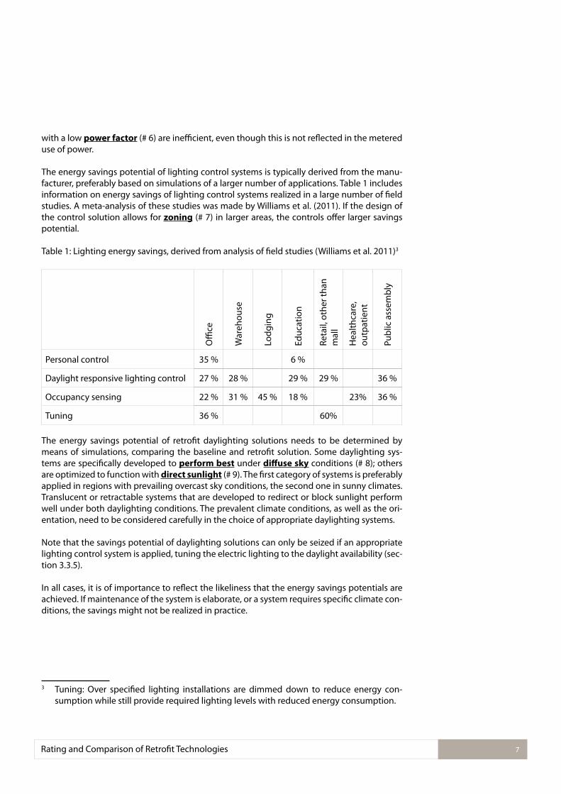
The energy savings potential of lighting control systems is typically derived from the manu-facturer, preferably based on simulations of a larger number of applications. Table 1 includes information on energy savings of lighting control systems realized in a large number of ield studies. A meta-analysis of these studies was made by Williams et al. (2011). If the design of the control solution allows for zoning (# 7) in larger areas, the controls ofer larger savings potential.
Table 1: Lighting energy savings, derived from analysis of ield studies (Williams et al. 2011)3
Oi
ce
War
ehou
se
Lod
gin
g
Edu
cati
on
Reta
il, o
ther
than
m
all
Hea
lth
care
, ou
tpat
ien
t
Pub
lic a
ssem
bly
Personal control 35 % 6 %
Daylight responsive lighting control 27 % 28 % 29 % 29 % 36 %
Occupancy sensing 22 % 31 % 45 % 18 % 23% 36 %
Tuning 36 % 60%
The energy savings potential of retroit daylighting solutions needs to be determined by means of simulations, comparing the baseline and retroit solution. Some daylighting sys-tems are speciically developed to perform best under difuse sky conditions (# 8); others are optimized to function with direct sunlight (# 9). The irst category of systems is preferably applied in regions with prevailing overcast sky conditions, the second one in sunny climates. Translucent or retractable systems that are developed to redirect or block sunlight perform well under both daylighting conditions. The prevalent climate conditions, as well as the ori-entation, need to be considered carefully in the choice of appropriate daylighting systems.
Note that the savings potential of daylighting solutions can only be seized if an appropriate lighting control system is applied, tuning the electric lighting to the daylight availability (sec-tion 3.3.5).
In all cases, it is of importance to relect the likeliness that the energy savings potentials are achieved. If maintenance of the system is elaborate, or a system requires speciic climate con-ditions, the savings might not be realized in practice.
3 Tuning: Over speciied lighting installations are dimmed down to reduce energy con-sumption while still provide required lighting levels with reduced energy consumption.
Rating and Comparison of Retroit Technologies 7
This report focusses on the energy consumption by electric lighting and daylighting solu-tions. Nonetheless, it needs to be pointed out, that any lighting solutions has an impact on the energy consumption for cooling and heating of the building as well.
The energy consumed by the electric lighting can be considered as an internal load to the building. An improvement of the electric lighting solutions, such as more eicient techno-logy or more eicient control of the luminaire’s use, may lead to a signiicant reduction of the energy consumption of the electric lighting. This will impact the internal gains and related heating and cooling needs. In general, internal loads due to the lighting installation lead to a reduction of the heating needs or increase of cooling needs. In cold climates and/or in winter, internal loads may be beneicial, but too high internal loads may be a disadvantage in hot climates and/or in summer. Cooling energy savings can be a signiicant factor in the cost-ef-fectiveness of retroit solutions. For every additional W put into the system, not needed for heating up the building, approximately 2.7 W of cool air needs to be produced. The cost-ef-fectiveness is afected by the energy source as well, heating typically relies on the use of gas, whereas cooling and lighting use electrical energy.
Daylight usage can afect the thermal requirements in building as well and change the energy used for cooling or heating. Solar radiation entering the room will increase the internal load, which may increase the need for cooling or reduced the need for heating. On the other hand, due to a lower thermal insulation of window panes, in comparison to the opaque part of the façade, additional thermal losses can occur. The interaction between lighting and HVAC, and its efect on the annual heating and cooling requirements should be considered in the overall assessment of product quality. Appropriate assessment of the overall energy consumption needs to be made building and context speciic, considering aspects such as, climate, orient-ation, actual window size and obstruction.
The Catalogue of Criteria looks at the performance on a product level only, and therefore includes a few of parameters that give an informative indication of the thermal performance only.
For daylighting solutions: » the measure for solar energy transmittance, the g value (# 10) of the system. The g value
is equal to the center-of-glass Solar Heat Gain Coeicient (SHGC), and ranges from 0 to 1, with a lower value representing less solar gain (classiication according to EN 14501),
» the maximum g value variation (# 11), for façade solutions that can change light and heat transmission properties according to changing needs, such as (re)moveable shading systems, electrochromics, thermochromics, and liquid crystals. The variation indicates the systems’ lexibility to respond to diferent sky conditions
» the light to thermal ratio (# 12, the light-to-solar-gain, LSG) , being a measure that indic-ates the ability of a daylighting solution to allow for an relatively higher daylight contribu-tion compared to the solar heat gain (“selectivity”),
» the secondary internal heat transfer, the qi value (# 13), describes the heat dissipation
due to convection and radiation of long-wave radiation from the system (classiication according to EN 14501).
Thermal impact of electric lighting solutions can be evaluated by means of system eicacy (# 1, in lm/W). More eicient solutions will require lower installed power and thus reducing the internal gain, which can be both beneicial and disadvantageous.
2.1.3 QUALITY MEASURES: THERMAL CONSIDERATIONS
Rating and Comparison of Retroit Technologies8
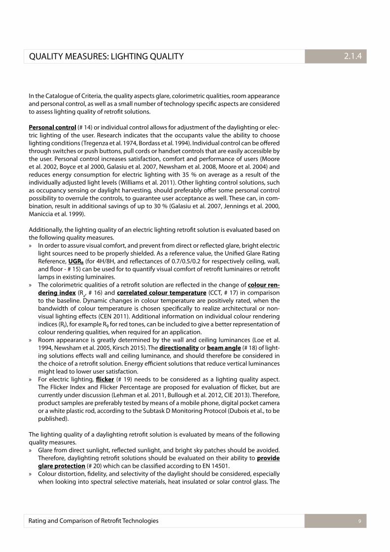
In the Catalogue of Criteria, the quality aspects glare, colorimetric qualities, room appearance and personal control, as well as a small number of technology speciic aspects are considered to assess lighting quality of retroit solutions.
Personal control (# 14) or individual control allows for adjustment of the daylighting or elec-tric lighting of the user. Research indicates that the occupants value the ability to choose lighting conditions (Tregenza et al. 1974, Bordass et al. 1994). Individual control can be ofered through switches or push buttons, pull cords or handset controls that are easily accessible by the user. Personal control increases satisfaction, comfort and performance of users (Moore et al. 2002, Boyce et al 2000, Galasiu et al. 2007, Newsham et al. 2008, Moore et al. 2004) and reduces energy consumption for electric lighting with 35 % on average as a result of the individually adjusted light levels (Williams et al. 2011). Other lighting control solutions, such as occupancy sensing or daylight harvesting, should preferably ofer some personal control possibility to overrule the controls, to guarantee user acceptance as well. These can, in com-bination, result in additional savings of up to 30 % (Galasiu et al. 2007, Jennings et al. 2000, Maniccia et al. 1999).
Additionally, the lighting quality of an electric lighting retroit solution is evaluated based on the following quality measures. » In order to assure visual comfort, and prevent from direct or relected glare, bright electric
light sources need to be properly shielded. As a reference value, the Uniied Glare Rating Reference, UGRR (for 4H/8H, and relectances of 0.7/0.5/0.2 for respectively ceiling, wall, and loor - # 15) can be used for to quantify visual comfort of retroit luminaires or retroit lamps in existing luminaires.
» The colorimetric qualities of a retroit solution are relected in the change of colour ren-
dering index (Ra, # 16) and correlated colour temperature (CCT, # 17) in comparison
to the baseline. Dynamic changes in colour temperature are positively rated, when the bandwidth of colour temperature is chosen speciically to realize architectural or non-visual lighting efects (CEN 2011). Additional information on individual colour rendering indices (Ri), for example R9 for red tones, can be included to give a better representation of colour rendering qualities, when required for an application.
» Room appearance is greatly determined by the wall and ceiling luminances (Loe et al. 1994, Newsham et al. 2005, Kirsch 2015). The directionality or beam angle (# 18) of light-ing solutions efects wall and ceiling luminance, and should therefore be considered in the choice of a retroit solution. Energy eicient solutions that reduce vertical luminances might lead to lower user satisfaction.
» For electric lighting, licker (# 19) needs to be considered as a lighting quality aspect. The Flicker Index and Flicker Percentage are proposed for evaluation of licker, but are currently under discussion (Lehman et al. 2011, Bullough et al. 2012, CIE 2013). Therefore, product samples are preferably tested by means of a mobile phone, digital pocket camera or a white plastic rod, according to the Subtask D Monitoring Protocol (Dubois et al., to be published).
The lighting quality of a daylighting retroit solution is evaluated by means of the following quality measures. » Glare from direct sunlight, relected sunlight, and bright sky patches should be avoided.
Therefore, daylighting retroit solutions should be evaluated on their ability to provide
glare protection (# 20) which can be classiied according to EN 14501. » Colour distortion, idelity, and selectivity of the daylight should be considered, especially
when looking into spectral selective materials, heat insulated or solar control glass. The
2.1.4QUALITY MEASURES: LIGHTING QUALITY
Rating and Comparison of Retroit Technologies 9
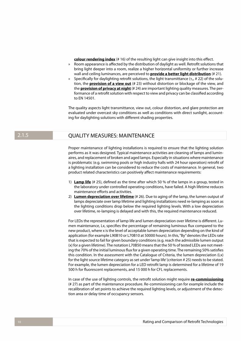
colour rendering index (# 16) of the resulting light can give insight into this efect. » Room appearance is afected by the distribution of daylight as well. Retroit solutions that
bring light deeper into a room, realize a higher horizontal uniformity or further increase wall and ceiling luminances, are perceived to provide a better light distribution (# 21).
» Speciically for daylighting retroit solutions, the light transmittance ( v, # 22) of the solu-tion, the provision of a view out (# 23) without distortion or blockage of the view, and the provision of privacy at night (# 24) are important lighting quality measures. The per-formance of a retroit solution with respect to view and privacy can be classiied according to EN 14501.
The quality aspects light transmittance, view out, colour distortion, and glare protection are evaluated under overcast sky conditions as well as conditions with direct sunlight, account-ing for daylighting solutions with diferent shading properties.
QUALITY MEASURES: MAINTENANCE
Proper maintenance of lighting installations is required to ensure that the lighting solution performs as it was designed. Typical maintenance activities are cleaning of lamps and lumin-aires, and replacement of broken and aged lamps. Especially in situations where maintenance is problematic (e.g. swimming pools or high industry halls with 24 hour operation) retroit of a lighting installation can be considered to reduce the costs of maintenance. In general, two product related characteristics can positively afect maintenance requirements:
1) Lamp life (# 25), deined as the time after which 50 % of the lamps in a group, tested in the laboratory under controlled operating conditions, have failed. A high lifetime reduces maintenance eforts and activities.
2) Lumen depreciation over lifetime (# 26). Due to aging of the lamp, the lumen output of lamps depreciate over lamp lifetime and lighting installations need re-lamping as soon as the lighting conditions drop below the required lighting levels. With a low depreciation over lifetime, re-lamping is delayed and with this, the required maintenance reduced.
For LEDs the representation of lamp life and lumen depreciation over lifetime is diferent. Lu-men maintenance, Lx, speciies the percentage of remaining luminous lux compared to the new product, where x is the level of acceptable lumen depreciation depending on the kind of application (for example L90B10 or L70B10 at 50000 hours). In this, “By” denotes the LEDs rate that is expected to fail for given boundary conditions (e.g. reach the admissible lumen output (x) for a given lifetime). The notation L70B50 means that the 50 % of tested LEDs are not meet-ing the 70% of the initial luminous lux for a given operating time. The remaining 50% satisies this condition. In the assessment with the Catalogue of Criteria, the lumen depreciation (Lx) for the light source lifetime category as set under ‘lamp life’ (criterion # 25) needs to be stated. For example, the lumen depreciation for a LED retroit lamp is determined for a lifetime of 19 500 h for luorescent replacements, and 15 000 h for CFL replacements.
In case of the use of lighting controls, the retroit solution might require re-commissioning (# 27) as part of the maintenance procedure. Re-commissioning can for example include the recalibration of set points to achieve the required lighting levels, or adjustment of the detec-tion area or delay time of occupancy sensors.
2.1.5
Rating and Comparison of Retroit Technologies10
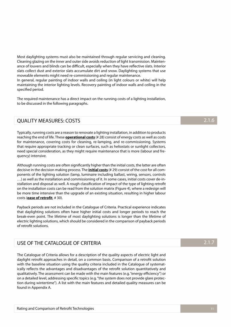
Most daylighting systems must also be maintained through regular servicing and cleaning. Cleaning glazing on the inner and outer side avoids reduction of light transmission. Mainten-ance of louvers and blinds can be diicult, especially when they have relective slats. Interior slats collect dust and exterior slats accumulate dirt and snow. Daylighting systems that use moveable elements might need re-commissioning and regular maintenance. In general, regular painting of indoor walls and ceiling (in light colours or white) will help maintaining the interior lighting levels. Recovery painting of indoor walls and ceiling in the speciied period.
The required maintenance has a direct impact on the running costs of a lighting installation, to be discussed in the following paragraphs.
QUALITY MEASURES: COSTS
Typically, running costs are a reason to renovate a lighting installation, in addition to products reaching the end of life. These operational costs (# 28) consist of energy costs as well as costs for maintenance, covering costs for cleaning, re-lamping, and re-commissioning. Systems that require appropriate tracking or clean surfaces, such as heliostats or sunlight collectors, need special consideration, as they might require maintenance that is more (labour and fre-quency) intensive.
Although running costs are often signiicantly higher than the initial costs, the latter are often decisive in the decision making process. The initial costs (# 29) consist of the cost for all com-ponents of the lighting solution (lamp, luminaire including ballast, wiring, sensors, controls …) as well as the installation and commissioning of it. In some cases, initial costs cover de-in-stallation and disposal as well. A rough classiication of impact of the type of lighting retroit on the installation costs can be read from the solution matrix (Figure 4), where a redesign will be more time intensive than the upgrade of an existing situation, resulting in higher labour costs (ease of retro�t, # 30).
Payback periods are not included in the Catalogue of Criteria. Practical experience indicates that daylighting solutions often have higher initial costs and longer periods to reach the break-even point. The lifetime of most daylighting solutions is longer than the lifetime of electric lighting solutions, which should be considered in the comparison of payback periods of retroit solutions.
USE OF THE CATALOGUE OF CRITERIA
The Catalogue of Criteria allows for a description of the quality aspects of electric light and daylight retroit approaches in detail, on a common basis. Comparison of a retroit solution with the baseline situation using the quality criteria included in the Catalogue of systemat-ically relects the advantages and disadvantages of the retroit solution quantitatively and qualitatively. The assessment can be made with the main features (e.g. “energy eiciency”) or on a detailed level, addressing speciic topics (e.g. “the system does not provide glare protec-tion during wintertime”). A list with the main features and detailed quality measures can be found in Appendix A.
2.1.6
2.1.7
Rating and Comparison of Retroit Technologies 11
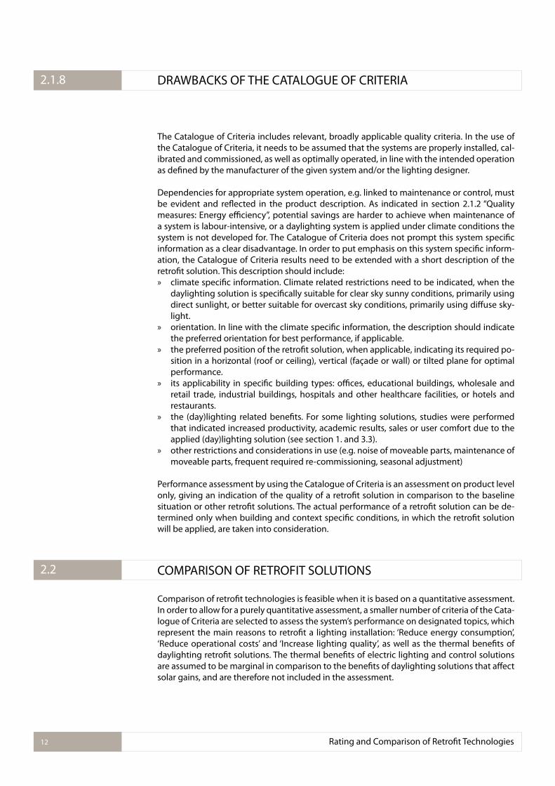
The Catalogue of Criteria includes relevant, broadly applicable quality criteria. In the use of the Catalogue of Criteria, it needs to be assumed that the systems are properly installed, cal-ibrated and commissioned, as well as optimally operated, in line with the intended operation as deined by the manufacturer of the given system and/or the lighting designer.
Dependencies for appropriate system operation, e.g. linked to maintenance or control, must be evident and relected in the product description. As indicated in section 2.1.2 “Quality measures: Energy eiciency”, potential savings are harder to achieve when maintenance of a system is labour-intensive, or a daylighting system is applied under climate conditions the system is not developed for. The Catalogue of Criteria does not prompt this system speciic information as a clear disadvantage. In order to put emphasis on this system speciic inform-ation, the Catalogue of Criteria results need to be extended with a short description of the retroit solution. This description should include: » climate speciic information. Climate related restrictions need to be indicated, when the
daylighting solution is speciically suitable for clear sky sunny conditions, primarily using direct sunlight, or better suitable for overcast sky conditions, primarily using difuse sky-light.
» orientation. In line with the climate speciic information, the description should indicate the preferred orientation for best performance, if applicable.
» the preferred position of the retroit solution, when applicable, indicating its required po-sition in a horizontal (roof or ceiling), vertical (façade or wall) or tilted plane for optimal performance.
» its applicability in speciic building types: oices, educational buildings, wholesale and retail trade, industrial buildings, hospitals and other healthcare facilities, or hotels and restaurants.
» the (day)lighting related beneits. For some lighting solutions, studies were performed that indicated increased productivity, academic results, sales or user comfort due to the applied (day)lighting solution (see section 1. and 3.3).
» other restrictions and considerations in use (e.g. noise of moveable parts, maintenance of moveable parts, frequent required re-commissioning, seasonal adjustment)
Performance assessment by using the Catalogue of Criteria is an assessment on product level only, giving an indication of the quality of a retroit solution in comparison to the baseline situation or other retroit solutions. The actual performance of a retroit solution can be de-termined only when building and context speciic conditions, in which the retroit solution will be applied, are taken into consideration.
COMPARISON OF RETROFIT SOLUTIONS
Comparison of retroit technologies is feasible when it is based on a quantitative assessment. In order to allow for a purely quantitative assessment, a smaller number of criteria of the Cata-logue of Criteria are selected to assess the system’s performance on designated topics, which represent the main reasons to retroit a lighting installation: ‘Reduce energy consumption’, ‘Reduce operational costs’ and ‘Increase lighting quality’, as well as the thermal beneits of daylighting retroit solutions. The thermal beneits of electric lighting and control solutions are assumed to be marginal in comparison to the beneits of daylighting solutions that afect solar gains, and are therefore not included in the assessment.
2.1.8 DRAWBACKS OF THE CATALOGUE OF CRITERIA
2.2
Rating and Comparison of Retroit Technologies12
At present, energy eiciency is represented by the energy savings potential of a lighting ret-roit solution. Lighting quality is addressed by visual comfort, colorimetric qualities, room appearance, and personal control possibilities. For daylighting solutions, this list of lighting quality aspects is extended with view out, privacy and light transmittance, as these aspects are also of utmost importance in the overall lighting quality assessment. To assess costs of retroit solutions, both initial costs and operational costs are considered in the product com-parison. In the assessment of daylighting systems, thermal considerations are included as additional information, relevant for the overall energy savings potential, even though the thermal considerations are not included in the savings potential.
The relevance of each item within the main categories should be deined in a project and be relected in weighting factors per item. Examples for weighting factors, as used within IEA Task 50, are given in Chapter 4.
Baseline conditions are, again, used to relect the performance of a retroit solution, allowing for product comparison. An evaluation and a comparison of innovative retroit techniques as well as state-of-the art solutions, of electric lighting and daylighting retroit solutions is possible.
REPRESENTATION OF TECHNOLOGY PERFORMANCE
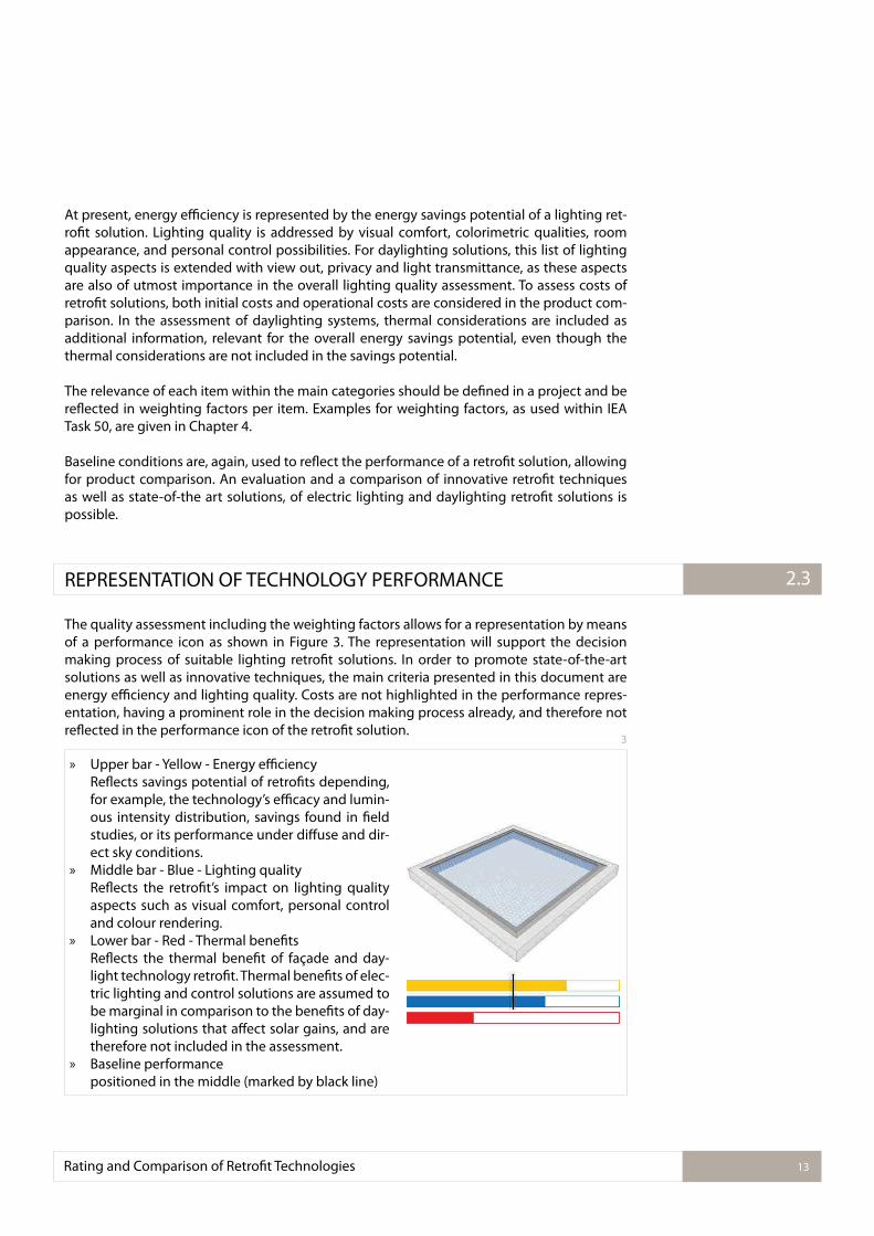
The quality assessment including the weighting factors allows for a representation by means of a performance icon as shown in Figure 3. The representation will support the decision making process of suitable lighting retroit solutions. In order to promote state-of-the-art solutions as well as innovative techniques, the main criteria presented in this document are energy eiciency and lighting quality. Costs are not highlighted in the performance repres-entation, having a prominent role in the decision making process already, and therefore not relected in the performance icon of the retroit solution.
Rating and Comparison of Retroit Technologies 13
2.3
3
» Upper bar - Yellow - Energy eiciencyRelects savings potential of retroits depending, for example, the technology’s eicacy and lumin-ous intensity distribution, savings found in ield studies, or its performance under difuse and dir-ect sky conditions.
» Middle bar - Blue - Lighting qualityRelects the retroit’s impact on lighting quality aspects such as visual comfort, personal control and colour rendering.
» Lower bar - Red - Thermal beneitsRelects the thermal beneit of façade and day-light technology retroit. Thermal beneits of elec-tric lighting and control solutions are assumed to be marginal in comparison to the beneits of day-lighting solutions that afect solar gains, and are therefore not included in the assessment.
» Baseline performance positioned in the middle (marked by black line)
3. OVERVIEW OF SOLUTIONS
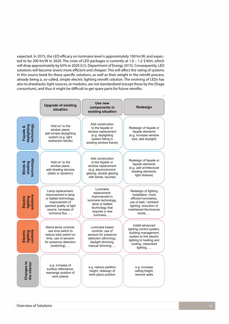
As indicated in the introduction, retroit by means of simple lamp or luminaire replacements are widely accepted, due to its efectiveness from an economic point of view, focusing on energy savings for electric lighting and payback periods. The remaining retroit solutions, tak-ing into account the usage of other components or a new design of the lighting installation are often neglected in the retroit process. The unsatisfactory implementation of unconven-tional retroit solutions is partly due to the abundance of approaches, and the great diversity amongst them. To structure the variety of solutions, a matrix was developed (see Figure 4) to present these.
A. in the following categories: » daylighting solutions (façade & daylighting technology + blinds & shading technology), » electric lighting solutions (electric lighting solutions + electric lighting controls), » changes to the building interior that afect the lighting conditions.
B. according to the retroit process: » Upgrade of the existing situation,
realized by, for example, replacing the lamps in an electric lighting installation with lamps with a higher eiciency, adding a simple daylighting system to improve user comfort or painting the walls to increase room surface relectance.
» Use of new components in an existing situation, such as the replacement of a window with one that has glazing with improved thermal qualities, the replacement of a luminaire with one that has a more suitable luminous dis-tribution, and replacement of partitions in an open plan oice with partitions with re-duced height.
» Redesign, the so called deep retroit,for example, of a roof by adding sky lights, of an electric lighting installation by changing from general lighting to a task / ambient lighting solution, or of the building interior by removing walls.
It needs to be pointed out that these retroit options are addressed in diferent design stages, for both daylighting and electric lighting. According to the Advanced Energy Retroit Guides (EREE 2011, 2013), standard retroit solutions (upgrade and use of a new component) ofer approximately 25 – 45% savings for electric energy, a deep retroit ofers more than 45% en-ergy savings, but typically has higher investments and longer payback periods.
In the following chapters, product families of lighting retroit technologies are evaluated, and an overall performance assessment for each type / family of retroit solution is given. As an example, LED solutions for T8 replacement are available in a large variety. The products con-sidered in the performance assessment are replacement lamps ofered by larger, well-known, manufacturers. Resulting, the performance icon (see Figure 3) and the representation of the main features in technology descriptions (as can be found in chapter 4) will not relect the performance of all LED solutions for T8 replacement available on the market. The technology descriptions can include relevant information about outliners in performance, pointing out possible quality restrictions, whenever this information is available. It remains of importance to assess the actual performance of a speciic product before implementation in a retroit project, for example by means of the Catalogue of Criteria.
Evaluations are based on state-of-the-art technology (to date – February 2016). With respect to daylighting retroit solutions, no relevant changes in technology are expected in the com-ing 5 years. With respect to electric lighting solutions, especially LED, signiicant changes are
Overview of Solutions14
expected. In 2015, the LED eicacy on luminaire level is approximately 100 lm/W, and expec-ted to be 200 lm/W in 2020. The costs of LED packages is currently at 1.0 – 1.2 $/klm, which will drop approximately by 65% in 2020 (U.S. Department of Energy 2015). Consequently, LED solutions will become (even) more eicient and cheaper. This will afect the rating of systems in this source book for these speciic solutions, as well as their weight in the retroit process, already being a, so-called, simple electric lighting retroit solution. The evolving of LEDs has also its drawbacks; light sources, or modules, are not standardized (except those by the Zhaga consortium), and thus it might be diicult to get spare parts for future retroits.
4
Overview of Solutions 15
Elec
tric
lig
htin
g so
lutio
ns
Elec
tric
light
ing
cont
rols
Cha
nges
to
the
inte
rior
Blin
ds &
sh
adin
g te
chno
logy
Faça
de &
da
ylig
htin
g te
chno
logy
Lamp replacement: improvement in lamp or ballast technology,
improvement of spectral quality of light
source, increase of luminous flux, …
Stand-alone controls: use time switch to
reduce total switch-on time, use of sensors
for presence detection (switching), …
e.g. increase of surface reflectance, rearrange position of
work places
Upgrade of existing situation
‘Add on’ to the window plane:
add shading devices (static or dynamic)
‘Add on’ to the window plane:
add simple daylighting system (e.g. light redirection blinds)
Luminaire replacement:
improvement in luminaire technology,
lamp or ballast technology that requires a new luminaire, …
Luminaire based controls: use of
sensors for presence detection (dimming),
daylight dimming, manual dimming, …
e.g. reduce partition height, redesign of work place position
Use new components in
existing situation
Add construction to the façade or
window replacement (e.g. electrochromic
glazing, double glazing with blinds, louvres)
Add construction to the façade or
window replacement (e.g. daylighting system fitting in
existing window frame)
Redesign of lighting installation: more
efficient luminaires, use of task / ambient lighting, reduction of
maintained illuminance levels, …
Install advanced lighting control system, building management system to link electric lighting to heating and
cooling, networked lighting, …
e.g. increase ceiling height, remove walls
Redesign
Redesign of façade or façade elements
(e.g. add architectural shading elements,
light shelves)
Redesign of façade or façade elements
(e.g. increase window size, add skylight)
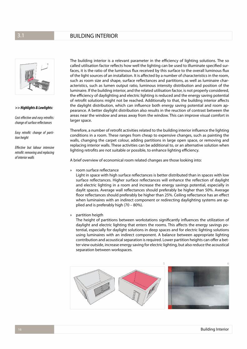
The building interior is a relevant parameter in the eiciency of lighting solutions. The so called utilisation factor relects how well the lighting can be used to illuminate speciied sur-faces, it is the ratio of the luminous lux received by this surface to the overall luminous lux of the light sources of an installation. It is afected by a number of characteristics in the room, such as room size and shape, surface relectances and partitions, as well as luminaire char-acteristics, such as lumen output ratio, luminous intensity distribution and position of the luminaire. If the building interior, and the related utilisation factor, is not properly considered, the eiciency of daylighting and electric lighting is reduced and the energy saving potential of retroit solutions might not be reached. Additionally to that, the building interior afects the daylight distribution, which can inluence both energy saving potential and room ap-pearance. A better daylight distribution also results in the reuction of contrast between the areas near the window and areas away from the window. This can improve visual comfort in larger space.
Therefore, a number of retroit activities related to the building interior inluence the lighting conditions in a room. These ranges from cheap to expensive changes, such as painting the walls, changing the carpet colour, adding partitions in large open space, or removing and replacing interior walls. These activities can be additional to, or an alternative solution when lighting retroits are not suitable or possible, to enhance lighting eiciency.
A brief overview of economical room related changes are those looking into:
» room surface relectance Light in space with high surface relectances is better distributed than in spaces with low surface relectances. Higher surface relectances will enhance the relection of daylight and electric lighting in a room and increase the energy savings potential, especially in daylit spaces. Average wall relectances should preferably be higher than 50%. Average loor relectances should preferably be higher than 25%. Ceiling relectance has an efect when luminaires with an indirect component or redirecting daylighting systems are ap-plied and is preferably high (70 – 80%).
» partition heigthThe height of partitions between workstations signiicantly inluences the utilization of daylight and electric lighting that enters the rooms. This afects the energy savings po-tential, especially for daylight solutions in deep spaces and for electric lighting solutions using luminaires with an indirect component. A balance between appropriate lighting contribution and acoustical separation is required. Lower partition heights can ofer a bet-ter view outside, increase energy saving for electric lighting, but also reduce the acoustical separation between workspaces.
>> Highlights & Lowlights:
Cost efective and easy retroits:
change of surface relectances
Easy retroit: change of parti-
tion height
Efective but labour intensive
retroit: removing and replacing
of interior walls
Building Interior16
3.2.1. BUILDING INTERIOR3.1
5 6
Building Interior 17
» relection of partitions and furnitureThe impact of relectances of vertical surfaces of a workstation on energy savings po-tentials is higher for indirect luminaires, as they rely on these surfaces to illuminate the desk. Lower relection of partitions also reduces the daylight levels deeper into a room. Transparent partitions could be considered, as they provide acoustical privacy as well as improved dalyight performance in the interior space.
Building retroits that consider removing interior walls or replacing interior walls with glass walls will typically increase lighting eiciency. This retroit approach is more expensive and can be considered in a deep retroit only.
It should be noted that aesthetic and interior design considerations can overpower the con-sideration of improved lighting distribution.
>> References
Newsham and Sander (2003): The Efect of oice design on workstation lighting: a simulation study. Dubois and Blomsterberg (2011): Energy saving potential and strategies for electric lighting in future North European, low energy oice buildings: A literature reviewGratia and De Herde (2003): Design of low energy oice buildingsBaker and Steemers (2014) Daylight design of buildings: A handbook for architects and en-gineers
9 © 10
7 8
In view of the inite reserve of fossil fuels, daylight should be the primary source of lighting in buildings. Appropriate daylighting design is required, to ensure that the overall use of en-ergy is minimized. This includes the energy use for electric lighting, cooling and heating as a result of the daylight design. Increased cooling or reduced heating might be the result of the thermal load of sunlight entering the room. Supplementary heating might be required because increased window size leads to additional thermal losses. Summarized, increased daylight utilization could increase energy consumption if energy to compensate for the addi-tional thermal load (cooling load) and / or thermal losses (heating load) exceeds the energy saved by reducing the use of electric lighting.
In the overall energy consumption, geographical position plays a role. For example, a study of ive daylight regions in North American showed that energy savings fall with rising latitude and total annual solar radiation, with the biggest diferences in the winter months due to the shorter day lengths with increasing latitude (Reinhart 2002). However, an analysis of the applicability of a large number of retroit options as such (EERE 2011 and 2013) indicates that the climate as such does not play a signiicant role in the efectiveness of the studied options (daylight harvesting, replacing windows, add exterior window ilm, window shading or light shelves, as well as the retroit of interior ixtures and occupancy sensors).
Orientation plays a role when considering daylight utilization as well. On the northern hemi-sphere, the use of daylight from north facing façades is more efective to save energy in sunny climates, whereas the overall energy consumption in cold climates is lower for south facing façades when daylight is used to illuminate the building. For the southern hemisphere for respectively the south and north facing façades.
Even though the actual performance is depending on climate and orientation, it will not be included in the energy eiciency assessment of the retroit products presented in this report. If geographical location or orientation is an important factor, it will be mentioned in the de-scription of the product.
Daylight utilization afects the switch-on probability for electric lighting, which in result in-luences energy consumption for electrical lighting. Switching tends to be correlated to min-imum indoor illuminance levels at the work plane upon arrival (Hunt, 1979; Love, 1998; Rein-hart 2004). Likely as a result of this, higher levels of energy savings are achieved with manual control of electric lighting in daylit spaces compared to spaces without daylight.
As indicated in the introduction, daylight utilization ofers beneits beyond the reduction of energy for electric lighting. It is generally acknowledged that occupants prefer daylight to electric lighting. Daylight can positively afect stress, well-being and mood. Additionally to
Façade and Daylight Technology18
3.2.1. FAÇADE AND DAYLIGHT TECHNOLOGY 3.2
11
that, it is efective in causing visual and non-visual responses, due to its availability in large amounts during the day, the strong blue component in its spectrum, and its excellent colour rendering qualities. Studies have indicated that daylight can increase productivity, academic results as well as user comfort (e.g. reviews of Boyce et al. 2003, Veitch and Galasiu (2012) and Strong (2012), studies conducted by the Heschong Mahone Group (California Energy Com-mission (2003a, 2003b) and http://h-m-g.com/Projects/daylighting/projects-PIER.htm) and ongoing work of the CIE Joint Technical Committee on “Visual, Health, and Environmental Be-neits of Windows in Buildings during Daylight”). Studies also indicate that daylight utilization can increase sales (Heschong et al. 2002).
Up until today, these beneits cannot be quantiied in an economical value or be represented in the lighting quality. Nonetheless, research indicates that the most important attributes of windows are the admission of daylight and the view out. In order to get an impression of the daylight provision for human related aspects, speciic consideration of a small number of quality criteria, such as light distribution in the room (criterion # 21) and view out (# 23), could be considered in the decision for a daylighting retroit solution. Increasing the glazing area in the building envelope, by adding skylights or enlarging the window size, will positively afect the daylight contribution.
Resulting, daylighting retroit solutions should be applied to modulate and enhance daylight admittance, especially under sunny conditions, to reduce energy consumption for electric lighting, while increasing user comfort. These systems focus on the appropriate use of day-light under sunny sky conditions: » blocking the sunlight, to prevent glare and overheating, but letting in difuse sky light, or » redirecting sunlight into the room to increase lighting levels while reducing direct glare
from sunlight. In both cases, a better use of daylight is realized in comparison to the situation with a closed sunshading system which prevents daylight utilization under sunny conditions completely (see baseline, section 2.1.1)
This source book includes a number of eicient daylighting retroit solutions. Additional in-formation on daylighting solutions can be found in the IEA Task 21 source book (Ruck et al. 2000) or at the Database of Light Interacting Technologies for Envelopes (D-LITE, http://d-lite.org/).
On the following pages, the performance of selected retroit solutions is described in detail, and structured according to Figure 4.
>> Redesign
Adding an opening to or increasing the size of an opening in the building envelop will result in a redesign of the façade or the roof. Even when the product costs as such might not be very high, this retroit solution will have high labour and constructional costs. The window opening can increase solar gains and thermal losses as well, which might afect the overall energy balance of the building. The resulting long payback period for these retroit solutions might be balanced out by the inancial, human-performance and psychological beneits of the higher daylight contribution in the building.
Retroit technologies: skylights, acrylic skylights, light tubes, lamellae heliostats, translucent skylight systems, micro sunshading louvres, light shelves and enlargement of window area (Section 3.2.1 - 3.2.8)
Façade and Daylight Technology 19
Façade and Daylight Technology20
>> Use of new components
Adding a construction to the façade. Replacing a window with one that has diferent charac-teristics increasing either energy eiciency, such as glazing with improved thermal qualities, or lighting quality, such as solutions that provide glare protection and a view under sunny sky conditions.
Retroit technologies: Louvres, shutters, electrochromic glazing, micro lamellae, microstruc-tured glazing, prismatic elements, laser cut panels (Section 3.2.9 - 3.2.16) and (redirecting)blinds integrated in an insulating glass unit (Section 3.2.18 and 3.2.19).
>> Upgrade of existing situation
A system can be retroitted by means of adding a daylighting technology to the existing situ-ation. These solutions are typically added on the outside of the façade. In this, the devices can reduce the cooling load of buildings (23% - 89%, with the highest savings obtained for solutions with a low shading coeicient (Dubois 2001). External systems nonetheless need to be robust, not to be afected by outdoor weather conditions. These systems might need more maintenance, which can be more diicult when not directly accessible from the building. Internal systems are sheltered from wind, rain, temperature changes and snow, and are typic-ally less expensive than external systems, but do not provide thermal beneits. Both solutions can ofer personal and glare control.
Retroit technologies: sun protection ilms, blinds, exterior redirecting blinds, stainless steel roller shutters, sunscreens (Section 3.2.17 - 3.2.22)
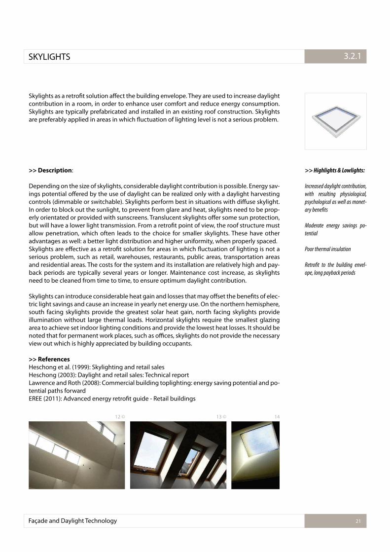
Skylights as a retroit solution afect the building envelope. They are used to increase daylight contribution in a room, in order to enhance user comfort and reduce energy consumption. Skylights are typically prefabricated and installed in an existing roof construction. Skylights are preferably applied in areas in which luctuation of lighting level is not a serious problem.
>> Description:
Depending on the size of skylights, considerable daylight contribution is possible. Energy sav-ings potential ofered by the use of daylight can be realized only with a daylight harvesting controls (dimmable or switchable). Skylights perform best in situations with difuse skylight. In order to block out the sunlight, to prevent from glare and heat, skylights need to be prop-erly orientated or provided with sunscreens. Translucent skylights ofer some sun protection, but will have a lower light transmission. From a retroit point of view, the roof structure must allow penetration, which often leads to the choice for smaller skylights. These have other advantages as well: a better light distribution and higher uniformity, when properly spaced. Skylights are efective as a retroit solution for areas in which luctuation of lighting is not a serious problem, such as retail, warehouses, restaurants, public areas, transportation areas and residential areas. The costs for the system and its installation are relatively high and pay-back periods are typically several years or longer. Maintenance cost increase, as skylights need to be cleaned from time to time, to ensure optimum daylight contribution.
Skylights can introduce considerable heat gain and losses that may ofset the beneits of elec-tric light savings and cause an increase in yearly net energy use. On the northern hemisphere, south facing skylights provide the greatest solar heat gain, north facing skylights provide illumination without large thermal loads. Horizontal skylights require the smallest glazing area to achieve set indoor lighting conditions and provide the lowest heat losses. It should be noted that for permanent work places, such as oices, skylights do not provide the necessary view out which is highly appreciated by building occupants.
>> References
Heschong et al. (1999): Skylighting and retail sales Heschong (2003): Daylight and retail sales: Technical reportLawrence and Roth (2008): Commercial building toplighting: energy saving potential and po-tential paths forwardEREE (2011): Advanced energy retroit guide - Retail buildings
>> Highlights & Lowlights:
Increased daylight contribution,
with resulting physiological,
psychological as well as monet-
ary beneits
Moderate energy savings po-
tential
Poor thermal insulation
Retroit to the building envel-
ope, long payback periods
Façade and Daylight Technology 21
3.2.1.SKYLIGHTS 3.2.1
12 © 13 © 14
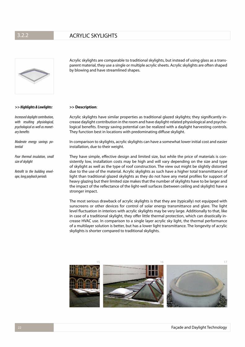
Acrylic skylights are comparable to traditional skylights, but instead of using glass as a trans-parent material, they use a single or multiple acrylic sheets. Acrylic skylights are often shaped by blowing and have streamlined shapes.
>> Description:
Acrylic skylights have similar properties as traditional glazed skylights; they signiicantly in-crease daylight contribution in the room and have daylight-related physiological and psycho-logical beneits. Energy saving potential can be realized with a daylight harvesting controls. They function best in locations with predominating difuse skylight.
In comparison to skylights, acrylic skylights can have a somewhat lower initial cost and easier installation, due to their weight.
They have simple, efective design and limited size, but while the price of materials is con-sistently low, installation costs may be high and will vary depending on the size and type of skylight as well as the type of roof construction. The view out might be slightly distorted due to the use of the material. Acrylic skylights as such have a higher total transmittance of light than traditional glazed skylights as they do not have any metal proiles for support of heavy glazing but their limited size makes that the number of skylights have to be larger and the impact of the relectance of the light-well surfaces (between ceiling and skylight) have a stronger impact.
The most serious drawback of acrylic skylights is that they are (typically) not equipped with sunscreens or other devices for control of solar energy transmittance and glare. The light level luctuation in interiors with acrylic skylights may be very large. Additionally to that, like in case of a traditional skylight, they ofer little thermal protection, which can drastically in-crease HVAC use. In comparison to a single layer acrylic sky light, the thermal performance of a multilayer solution is better, but has a lower light transmittance. The longevity of acrylic skylights is shorter compared to traditional skylights.
>> Highlights & Lowlights:
Increased daylight contribution,
with resulting physiological,
psychological as well as monet-
ary beneits
Moderate energy savings po-
tential
Poor thermal insulation, small
size of skylight
Retroit to the building envel-
ope, long payback periods
Façade and Daylight Technology22
3.2.1. ACRYLIC SKYLIGHTS3.2.2
15 16 17
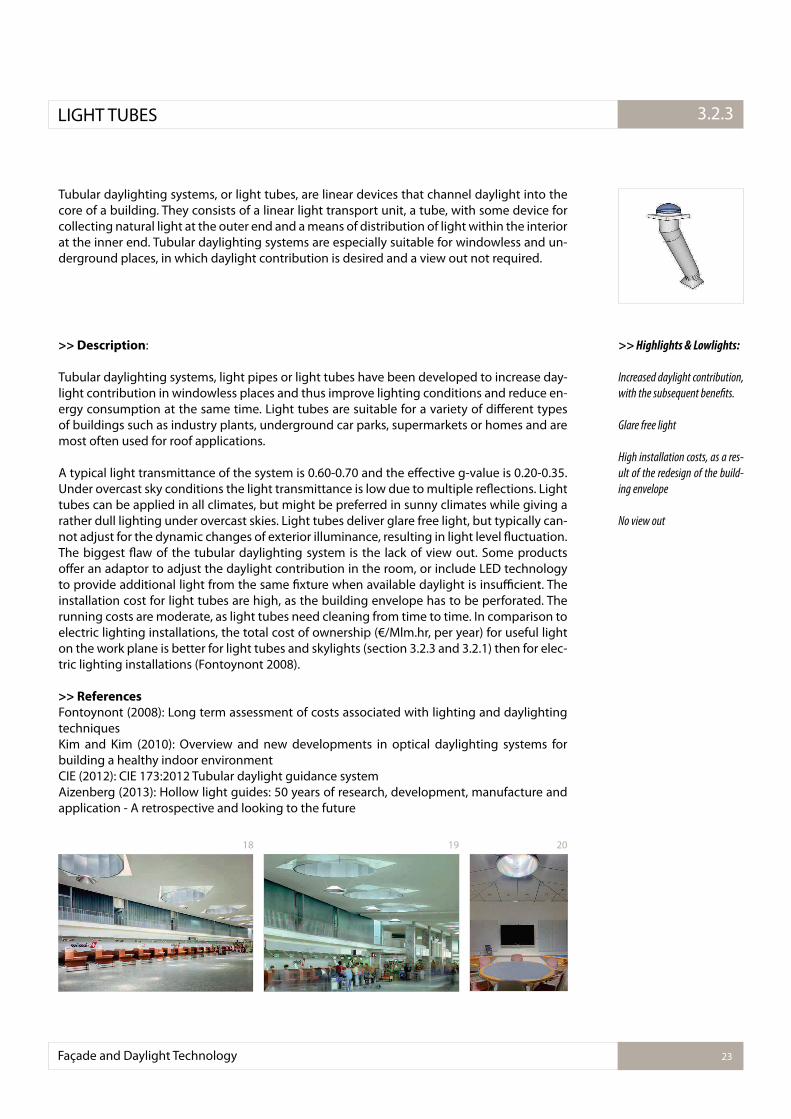
Tubular daylighting systems, or light tubes, are linear devices that channel daylight into the core of a building. They consists of a linear light transport unit, a tube, with some device for collecting natural light at the outer end and a means of distribution of light within the interior at the inner end. Tubular daylighting systems are especially suitable for windowless and un-derground places, in which daylight contribution is desired and a view out not required.
>> Description:
Tubular daylighting systems, light pipes or light tubes have been developed to increase day-light contribution in windowless places and thus improve lighting conditions and reduce en-ergy consumption at the same time. Light tubes are suitable for a variety of diferent types of buildings such as industry plants, underground car parks, supermarkets or homes and are most often used for roof applications.
A typical light transmittance of the system is 0.60-0.70 and the efective g-value is 0.20-0.35. Under overcast sky conditions the light transmittance is low due to multiple relections. Light tubes can be applied in all climates, but might be preferred in sunny climates while giving a rather dull lighting under overcast skies. Light tubes deliver glare free light, but typically can-not adjust for the dynamic changes of exterior illuminance, resulting in light level luctuation. The biggest law of the tubular daylighting system is the lack of view out. Some products ofer an adaptor to adjust the daylight contribution in the room, or include LED technology to provide additional light from the same ixture when available daylight is insuicient. The installation cost for light tubes are high, as the building envelope has to be perforated. The running costs are moderate, as light tubes need cleaning from time to time. In comparison to electric lighting installations, the total cost of ownership (€/Mlm.hr, per year) for useful light on the work plane is better for light tubes and skylights (section 3.2.3 and 3.2.1) then for elec-tric lighting installations (Fontoynont 2008).
>> References
Fontoynont (2008): Long term assessment of costs associated with lighting and daylighting techniquesKim and Kim (2010): Overview and new developments in optical daylighting systems for building a healthy indoor environmentCIE (2012): CIE 173:2012 Tubular daylight guidance systemAizenberg (2013): Hollow light guides: 50 years of research, development, manufacture and application - A retrospective and looking to the future
>> Highlights & Lowlights:
Increased daylight contribution,
with the subsequent beneits.
Glare free light
High installation costs, as a res-
ult of the redesign of the build-
ing envelope
No view out
Façade and Daylight Technology 23
3.2.1.LIGHT TUBES 3.2.3
18 19 20
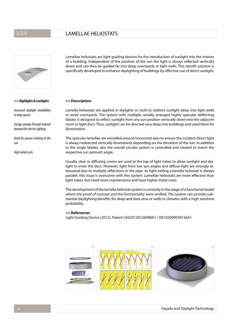
Lamellae heliostats are light guiding devices for the introduction of sunlight into the interior of a building. Independent of the position of the sun the light is always relected vertically down and can thus be guided far into deep courtyards or light wells. This retroit solution is speciically developed to enhance daylighting of buildings by efective use of direct sunlight.
>> Description:
Lamella heliostats are applied in skylights or roofs to redirect sunlight deep into light wells or inner courtyards. The system with multiple, serially arranged highly specular delecting blades is designed to relect sunlight from any sun position vertically down into the adjacent room or light duct. Thus, sunlight can be directed very deep into buildings and used there for illumination.
The specular lamellae are swivelled around horizontal axes to ensure the incident direct light is always redirected vertically downwards depending on the elevation of the sun. In addition to the single blades, also the overall circular system is controlled and rotated to match the respective sun azimuth angle.
Usually clear or difusing covers are used at the top of light tubes to allow sunlight and sky-light to enter the duct. However, light from low sun angles and difuse light are strongly at-tenuated due to multiple relections in the pipe. As light exiting a lamella heliostat is always parallel, this issue is overcome with this system. Lamellae heliostats are more efective than light tubes, but need more maintenance and have higher initial costs.
The development of the lamella heliostat system is currently in the stage of a functional model where the proof of concept and the functionality were veriied. The system can provide sub-stantial daylighting beneits for deep and dark atria or wells in climates with a high sunshine probability.
>> References
Light Guiding Device (2012), Patent US020120126098A1 / DE102009039136A1
>> Highlights & Lowlights:
Increased daylight availability
in deep spaces
Energy savings through reduced
demand for electric lighting
Need for precise tracking of the
sun
High initial costs
Façade and Daylight Technology24
3.2.1. LAMELLAE HELIOSTATS3.2.4
21 22 23
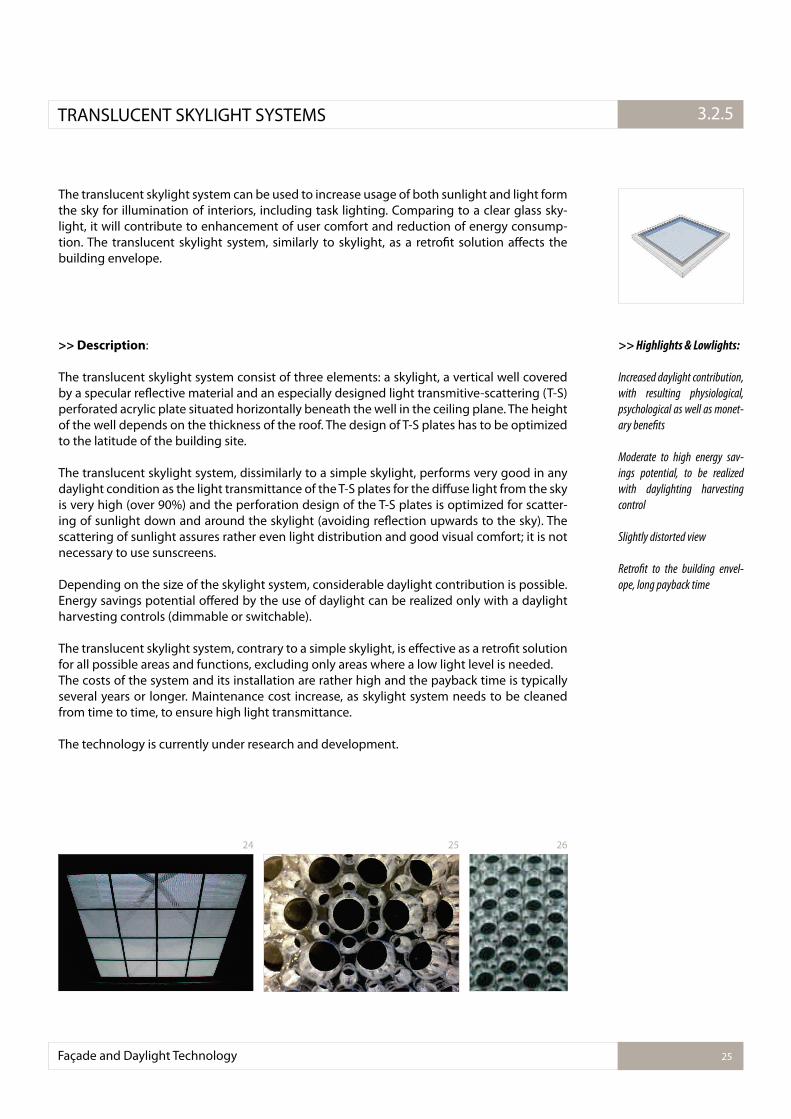
The translucent skylight system can be used to increase usage of both sunlight and light form the sky for illumination of interiors, including task lighting. Comparing to a clear glass sky-light, it will contribute to enhancement of user comfort and reduction of energy consump-tion. The translucent skylight system, similarly to skylight, as a retroit solution afects the building envelope.
>> Description:
The translucent skylight system consist of three elements: a skylight, a vertical well covered by a specular relective material and an especially designed light transmitive-scattering (T-S) perforated acrylic plate situated horizontally beneath the well in the ceiling plane. The height of the well depends on the thickness of the roof. The design of T-S plates has to be optimized to the latitude of the building site.
The translucent skylight system, dissimilarly to a simple skylight, performs very good in any daylight condition as the light transmittance of the T-S plates for the difuse light from the sky is very high (over 90%) and the perforation design of the T-S plates is optimized for scatter-ing of sunlight down and around the skylight (avoiding relection upwards to the sky). The scattering of sunlight assures rather even light distribution and good visual comfort; it is not necessary to use sunscreens.
Depending on the size of the skylight system, considerable daylight contribution is possible. Energy savings potential ofered by the use of daylight can be realized only with a daylight harvesting controls (dimmable or switchable).
The translucent skylight system, contrary to a simple skylight, is efective as a retroit solution for all possible areas and functions, excluding only areas where a low light level is needed. The costs of the system and its installation are rather high and the payback time is typically several years or longer. Maintenance cost increase, as skylight system needs to be cleaned from time to time, to ensure high light transmittance.
The technology is currently under research and development.
>> Highlights & Lowlights:
Increased daylight contribution,
with resulting physiological,
psychological as well as monet-
ary beneits
Moderate to high energy sav-
ings potential, to be realized
with daylighting harvesting
control
Slightly distorted view
Retroit to the building envel-
ope, long payback time
Façade and Daylight Technology 25
3.2.1.TRANSLUCENT SKYLIGHT SYSTEMS 3.2.5
24 25 26
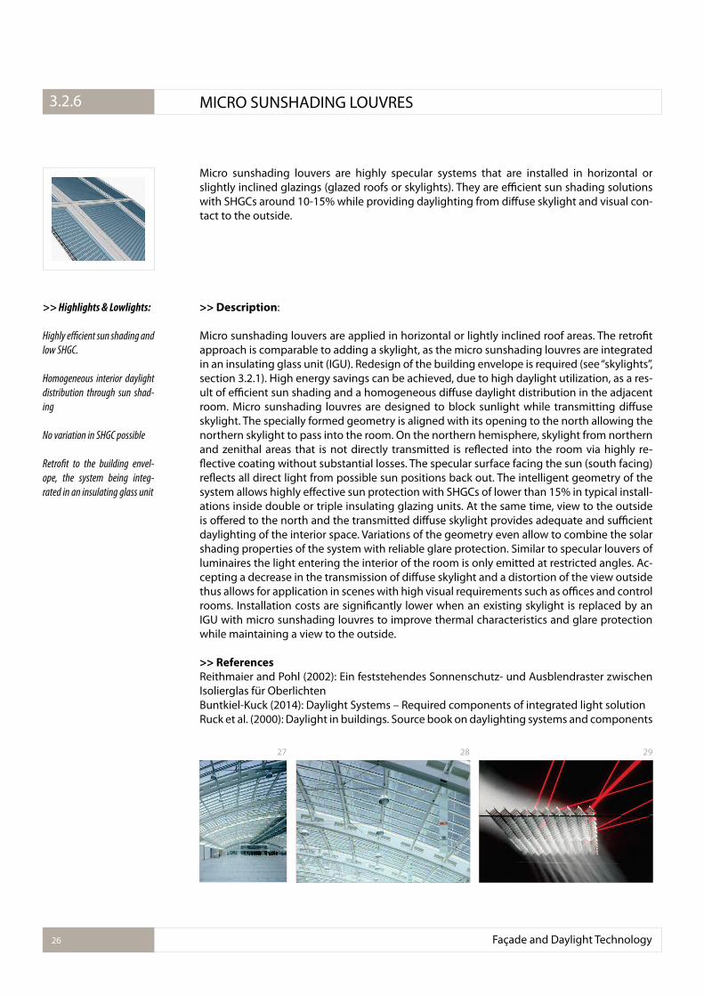
Micro sunshading louvers are highly specular systems that are installed in horizontal or slightly inclined glazings (glazed roofs or skylights). They are eicient sun shading solutions with SHGCs around 10-15% while providing daylighting from difuse skylight and visual con-tact to the outside.
>> Description:
Micro sunshading louvers are applied in horizontal or lightly inclined roof areas. The retroit approach is comparable to adding a skylight, as the micro sunshading louvres are integrated in an insulating glass unit (IGU). Redesign of the building envelope is required (see “skylights”, section 3.2.1). High energy savings can be achieved, due to high daylight utilization, as a res-ult of eicient sun shading and a homogeneous difuse daylight distribution in the adjacent room. Micro sunshading louvres are designed to block sunlight while transmitting difuse skylight. The specially formed geometry is aligned with its opening to the north allowing the northern skylight to pass into the room. On the northern hemisphere, skylight from northern and zenithal areas that is not directly transmitted is relected into the room via highly re-lective coating without substantial losses. The specular surface facing the sun (south facing) relects all direct light from possible sun positions back out. The intelligent geometry of the system allows highly efective sun protection with SHGCs of lower than 15% in typical install-ations inside double or triple insulating glazing units. At the same time, view to the outside is ofered to the north and the transmitted difuse skylight provides adequate and suicient daylighting of the interior space. Variations of the geometry even allow to combine the solar shading properties of the system with reliable glare protection. Similar to specular louvers of luminaires the light entering the interior of the room is only emitted at restricted angles. Ac-cepting a decrease in the transmission of difuse skylight and a distortion of the view outside thus allows for application in scenes with high visual requirements such as oices and control rooms. Installation costs are signiicantly lower when an existing skylight is replaced by an IGU with micro sunshading louvres to improve thermal characteristics and glare protection while maintaining a view to the outside.
>> References
Reithmaier and Pohl (2002): Ein feststehendes Sonnenschutz- und Ausblendraster zwischen Isolierglas für OberlichtenBuntkiel-Kuck (2014): Daylight Systems – Required components of integrated light solutionRuck et al. (2000): Daylight in buildings. Source book on daylighting systems and components
>> Highlights & Lowlights:
Highly e�cient sun shading and
low SHGC.
Homogeneous interior daylight
distribution through sun shad-
ing
No variation in SHGC possible
Retroit to the building envel-
ope, the system being integ-
rated in an insulating glass unit
Façade and Daylight Technology26
3.2.1. MICRO SUNSHADING LOUVRES3.2.6
27 28 29
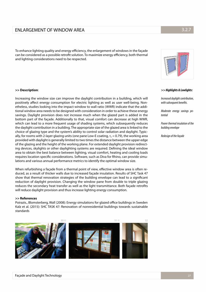
To enhance lighting quality and energy eiciency, the enlargement of windows in the façade can be considered as a possible retroit solution. To maximize energy eiciency, both thermal and lighting considerations need to be respected.
>> Description:
Increasing the window size can improve the daylight contribution in a building, which will positively afect energy consumption for electric lighting as well as user well-being. Non-etheless, studies looking into the impact window to wall ratio (WWR) indicate that the addi-tional window area needs to be designed with consideration in order to achieve these energy savings. Daylight provision does not increase much when the glazed part is added in the bottom part of the façade. Additionally to that, visual comfort can decrease at high WWR, which can lead to a more frequent usage of shading systems, which subsequently reduces the daylight contribution in a building. The appropriate size of the glazed area is linked to the choice of glazing type and the system’s ability to control solar radiation and daylight. Typic-ally, for rooms with 2-layer glazing units (one pane Low-E coating, v = 0.79), the working area provided with daylight is generally limited to two times the distance between the upper edge of the glazing and the height of the working plane. For extended daylight provision redirect-ing devices, skylights or other daylighting systems are required. Deining the ideal window area to obtain the best balance between lighting, visual comfort, heating and cooling loads requires location speciic considerations. Software, such as Diva for Rhino, can provide simu-lations and various annual performance metrics to identify the optimal window size.
When refurbishing a façade from a thermal point of view, efective window area is often re-duced, as a result of thicker walls due to increased façade insulation. Results of SHC Task 47 show that thermal renovation strategies of the building envelope can lead to a signiicant reduction of daylight provision. Changing the window pane from double to triple glazing reduces the secondary heat transfer as well as the light transmittance. Both façade retroits will reduce daylight provision and thus increase lighting energy consumption.
>> References
Poirazis., Blomsterberg, Wall (2008): Energy simulations for glazed oice buildings in SwedenKalz et al. (2015): SHC TASK 47: Renovation of nonresidential buildings towards sustainable standards
>> Highlights & Lowlights:
Increased daylight contribution,
with subsequent beneits.
Moderate energy savings po-
tential
Poorer thermal insulation of the
building envelope
Redesign of the façade
Façade and Daylight Technology 27
3.2.1.ENLARGEMENT OF WINDOW AREA 3.2.7
30 © 31 © 32
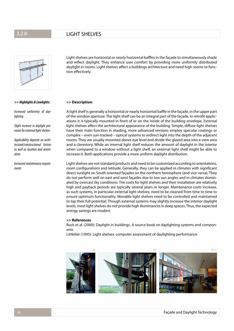
Light shelves are horizontal or nearly horizontal bales in the façade to simultaneously shade and relect daylight. They enhance user comfort by providing more uniformly distributed daylight in rooms. Light shelves afect a buildings architecture and need high rooms to func-tion efectively.
>> Description:
A light shelf is generally a horizontal or nearly horizontal bale in the façade, in the upper part of the window aperture. The light shelf can be an integral part of the façade, in retroit applic-ations it is typically mounted in front of or on the inside of the building envelope. External light shelves afect the architectural appearance of the building. Simple, difuse light shelves have their main function in shading, more advanced versions employ specular coatings or complex – even sun-tracked – optical systems to redirect light into the depth of the adjacent rooms. They are usually mounted above eye level and divide the glazed area into a view area and a clerestory. While an internal light shelf reduces the amount of daylight in the interior when compared to a window without a light shelf, an external light shelf might be able to increase it. Both applications provide a more uniform daylight distribution.
Light shelves are not standard products and need to be customized according to orientations, room conigurations and latitude. Generally, they can be applied in climates with signiicant direct sunlight on South oriented façades on the northern hemisphere (and vice versa). They do not perform well on east and west façades due to low sun angles and in climates domin-ated by overcast sky conditions. The costs for light shelves and their installation are relatively high and payback periods are typically several years or longer. Maintenance costs increase, as such systems, in particular external light shelves, need to be cleaned from time to time to ensure optimum functionality. Movable light shelves need to be controlled and maintained to tap their full potential. Though external systems may slightly increase the interior daylight levels, most light shelves do not provide high illuminances in deep spaces. Thus, the expected energy savings are modest.
>> References
Ruck et al. (2000): Daylight in buildings. A source book on daylighting systems and compon-entsLittlefair (1995): Light shelves: computer assessment of daylighting performance
>> Highlights & Lowlights:
Increased uniformity of day-
lighting
Slight increase in daylight pro-
vision for external light shelves
Applicability depends on archi-
tectural/constructional factors
as well as location and orient-
ation
Increased maintenance require-
ments
Façade and Daylight Technology28
3.2.1. LIGHT SHELVES3.2.8
33 34 35 ©
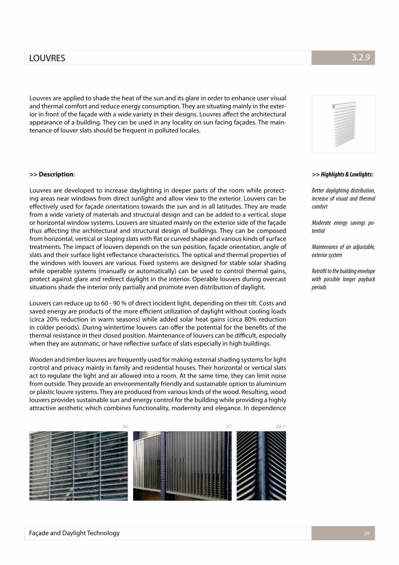
Louvres are applied to shade the heat of the sun and its glare in order to enhance user visual and thermal comfort and reduce energy consumption. They are situating mainly in the exter-ior in front of the façade with a wide variety in their designs. Louvres afect the architectural appearance of a building. They can be used in any locality on sun facing façades. The main-tenance of louver slats should be frequent in polluted locales.
>> Description:
Louvres are developed to increase daylighting in deeper parts of the room while protect-ing areas near windows from direct sunlight and allow view to the exterior. Louvers can be efectively used for façade orientations towards the sun and in all latitudes. They are made from a wide variety of materials and structural design and can be added to a vertical, slope or horizontal window systems. Louvers are situated mainly on the exterior side of the façade thus afecting the architectural and structural design of buildings. They can be composed from horizontal, vertical or sloping slats with lat or curved shape and various kinds of surface treatments. The impact of louvers depends on the sun position, façade orientation, angle of slats and their surface light relectance characteristics. The optical and thermal properties of the windows with louvers are various. Fixed systems are designed for stable solar shading while operable systems (manually or automatically) can be used to control thermal gains, protect against glare and redirect daylight in the interior. Operable louvers during overcast situations shade the interior only partially and promote even distribution of daylight.
Louvers can reduce up to 60 - 90 % of direct incident light, depending on their tilt. Costs and saved energy are products of the more eicient utilization of daylight without cooling loads (circa 20% reduction in warm seasons) while added solar heat gains (circa 80% reduction in colder periods). During wintertime louvers can ofer the potential for the beneits of the thermal resistance in their closed position. Maintenance of louvers can be diicult, especially when they are automatic, or have relective surface of slats especially in high buildings.
Wooden and timber louvres are frequently used for making external shading systems for light control and privacy mainly in family and residential houses. Their horizontal or vertical slats act to regulate the light and air allowed into a room. At the same time, they can limit noise from outside. They provide an environmentally friendly and sustainable option to aluminium or plastic louvre systems. They are produced from various kinds of the wood. Resulting, wood louvers provides sustainable sun and energy control for the building while providing a highly attractive aesthetic which combines functionality, modernity and elegance. In dependence
>> Highlights & Lowlights:
Better daylighting distribution,
increase of visual and thermal
comfort
Moderate energy savings po-
tential
Maintenance of an adjustable,
exterior system
Retroit to the building envelope
with possible longer payback
periods
Façade and Daylight Technology 29
3.2.1.LOUVRES 3.2.9
36 37 38 ©
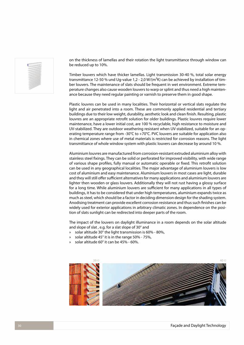
on the thickness of lamellas and their rotation the light transmittance through window can be reduced up to 10%.
Timber louvers which have thicker lamellas. Light transmission 30-40 %, total solar energy transmittance 12-50 % und Ug-value 1,2 - 2,0 W/(m²K) can be achieved by installation of tim-ber louvers. The maintenance of slats should be frequent in wet environment. Extreme tem-perature changes also cause wooden louvers to warp or splint and thus need a high mainten-ance because they need regular painting or varnish to preserve them in good shape.
Plastic louvres can be used in many localities. Their horizontal or vertical slats regulate the light and air penetrated into a room. These are commonly applied residential and tertiary buildings due to their low weight, durability, aesthetic look and clean inish. Resulting, plastic louvres are an appropriate retroit solution for older buildings. Plastic louvres require lower maintenance, have a lower initial cost, are 100 % recyclable, high resistance to moisture and UV-stabilized. They are outdoor weathering resistant when UV-stabilized, suitable for an op-erating temperature range from -30°C to +70°C. PVC louvers are suitable for application also in chemical zones where use of metal materials is restricted for corrosion reasons. The light transmittance of whole window system with plastic louvers can decrease by around 10 %.
Aluminium louvres are manufactured from corrosion-resistant extruded aluminium alloy with stainless steel ixings. They can be solid or perforated for improved visibility, with wide range of various shape proiles, fully manual or automatic operable or ixed. This retroit solution can be used in any geographical localities. The major advantage of aluminium louvers is low cost of aluminium and easy maintenance. Aluminium louvers in most cases are light, durable and they will still ofer suicient alternatives for many applications and aluminium louvers are lighter then wooden or glass louvers. Additionally they will not rust having a glossy surface for a long time. While aluminium louvers are suicient for many applications in all types of buildings, it has to be considered that under high temperatures, aluminium expands twice as much as steel, which should be a factor in deciding dimension design for the shading system. Anodising treatment can provide excellent corrosion resistance and thus such inishes can be widely used for exterior applications in arbitrary climatic zones. In dependence on the posi-tion of slats sunlight can be redirected into deeper parts of the room.
The impact of the louvers on daylight illuminance in a room depends on the solar altitude and slope of slat , e.g. for a slat slope of 30° and » solar altitude 30° the light transmission is 60% - 80%, » solar altitude 45° it is in the range 50% - 75%, » solar altitude 60° it can be 45% - 60%.
Façade and Daylight Technology30
39 © 40 ©
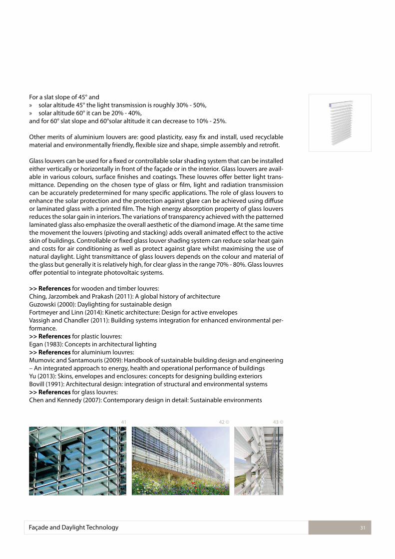
For a slat slope of 45° and » solar altitude 45° the light transmission is roughly 30% - 50%, » solar altitude 60° it can be 20% - 40%,
and for 60° slat slope and 60°solar altitude it can decrease to 10% - 25%.
Other merits of aluminium louvers are: good plasticity, easy ix and install, used recyclable material and environmentally friendly, lexible size and shape, simple assembly and retroit. Glass louvers can be used for a ixed or controllable solar shading system that can be installed either vertically or horizontally in front of the façade or in the interior. Glass louvers are avail-able in various colours, surface inishes and coatings. These louvres ofer better light trans-mittance. Depending on the chosen type of glass or ilm, light and radiation transmission can be accurately predetermined for many speciic applications. The role of glass louvers to enhance the solar protection and the protection against glare can be achieved using difuse or laminated glass with a printed ilm. The high energy absorption property of glass louvers reduces the solar gain in interiors. The variations of transparency achieved with the patterned laminated glass also emphasize the overall aesthetic of the diamond image. At the same time the movement the louvers (pivoting and stacking) adds overall animated efect to the active skin of buildings. Controllable or ixed glass louver shading system can reduce solar heat gain and costs for air conditioning as well as protect against glare whilst maximising the use of natural daylight. Light transmittance of glass louvers depends on the colour and material of the glass but generally it is relatively high, for clear glass in the range 70% - 80%. Glass louvres ofer potential to integrate photovoltaic systems.
>> References for wooden and timber louvres:Ching, Jarzombek and Prakash (2011): A global history of architectureGuzowski (2000): Daylighting for sustainable designFortmeyer and Linn (2014): Kinetic architecture: Design for active envelopesVassigh and Chandler (2011): Building systems integration for enhanced environmental per-formance. >> References for plastic louvres:Egan (1983): Concepts in architectural lighting>> References for aluminium louvres:Mumovic and Santamouris (2009): Handbook of sustainable building design and engineering – An integrated approach to energy, health and operational performance of buildingsYu (2013): Skins, envelopes and enclosures: concepts for designing building exteriorsBovill (1991): Architectural design: integration of structural and environmental systems>> References for glass louvres:Chen and Kennedy (2007): Contemporary design in detail: Sustainable environments
Façade and Daylight Technology 31
41 42 © 43 ©
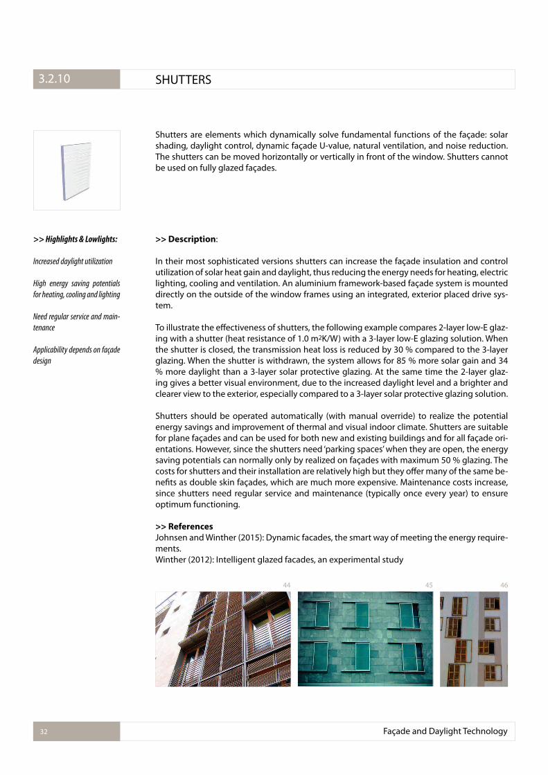
Shutters are elements which dynamically solve fundamental functions of the façade: solar shading, daylight control, dynamic façade U-value, natural ventilation, and noise reduction. The shutters can be moved horizontally or vertically in front of the window. Shutters cannot be used on fully glazed façades.
>> Description:
In their most sophisticated versions shutters can increase the façade insulation and control utilization of solar heat gain and daylight, thus reducing the energy needs for heating, electric lighting, cooling and ventilation. An aluminium framework-based façade system is mounted directly on the outside of the window frames using an integrated, exterior placed drive sys-tem.
To illustrate the efectiveness of shutters, the following example compares 2-layer low-E glaz-ing with a shutter (heat resistance of 1.0 m2K/W) with a 3-layer low-E glazing solution. When the shutter is closed, the transmission heat loss is reduced by 30 % compared to the 3-layer glazing. When the shutter is withdrawn, the system allows for 85 % more solar gain and 34 % more daylight than a 3-layer solar protective glazing. At the same time the 2-layer glaz-ing gives a better visual environment, due to the increased daylight level and a brighter and clearer view to the exterior, especially compared to a 3-layer solar protective glazing solution.
Shutters should be operated automatically (with manual override) to realize the potential energy savings and improvement of thermal and visual indoor climate. Shutters are suitable for plane façades and can be used for both new and existing buildings and for all façade ori-entations. However, since the shutters need ‘parking spaces’ when they are open, the energy saving potentials can normally only by realized on façades with maximum 50 % glazing. The costs for shutters and their installation are relatively high but they ofer many of the same be-neits as double skin façades, which are much more expensive. Maintenance costs increase, since shutters need regular service and maintenance (typically once every year) to ensure optimum functioning.
>> References
Johnsen and Winther (2015): Dynamic facades, the smart way of meeting the energy require-ments.Winther (2012): Intelligent glazed facades, an experimental study
>> Highlights & Lowlights:
Increased daylight utilization
High energy saving potentials
for heating, cooling and lighting
Need regular service and main-
tenance
Applicability depends on façade
design
Façade and Daylight Technology32
3.2.1. SHUTTERS3.2.10
44 45 46
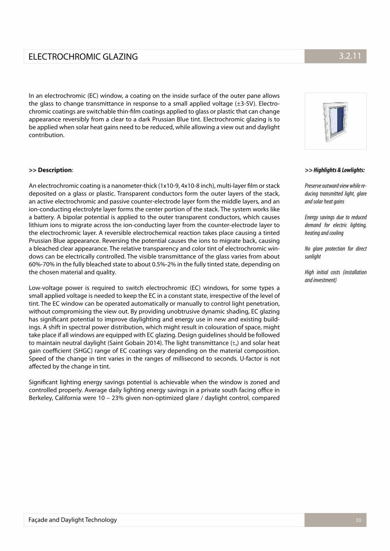
In an electrochromic (EC) window, a coating on the inside surface of the outer pane allows the glass to change transmittance in response to a small applied voltage (±3-5V). Electro-chromic coatings are switchable thin-ilm coatings applied to glass or plastic that can change appearance reversibly from a clear to a dark Prussian Blue tint. Electrochromic glazing is to be applied when solar heat gains need to be reduced, while allowing a view out and daylight contribution.
>> Description:
An electrochromic coating is a nanometer-thick (1x10⁻⁹, 4x10⁻⁸ inch), multi-layer ilm or stack deposited on a glass or plastic. Transparent conductors form the outer layers of the stack, an active electrochromic and passive counter-electrode layer form the middle layers, and an ion-conducting electrolyte layer forms the center portion of the stack. The system works like a battery. A bipolar potential is applied to the outer transparent conductors, which causes lithium ions to migrate across the ion-conducting layer from the counter-electrode layer to the electrochromic layer. A reversible electrochemical reaction takes place causing a tinted Prussian Blue appearance. Reversing the potential causes the ions to migrate back, causing a bleached clear appearance. The relative transparency and color tint of electrochromic win-dows can be electrically controlled. The visible transmittance of the glass varies from about 60%-70% in the fully bleached state to about 0.5%-2% in the fully tinted state, depending on the chosen material and quality.
Low-voltage power is required to switch electrochromic (EC) windows, for some types a small applied voltage is needed to keep the EC in a constant state, irrespective of the level of tint. The EC window can be operated automatically or manually to control light penetration, without compromising the view out. By providing unobtrusive dynamic shading, EC glazing has signiicant potential to improve daylighting and energy use in new and existing build-ings. A shift in spectral power distribution, which might result in colouration of space, might take place if all windows are equipped with EC glazing. Design guidelines should be followed to maintain neutral daylight (Saint Gobain 2014). The light transmittance ( v) and solar heat gain coeicient (SHGC) range of EC coatings vary depending on the material composition. Speed of the change in tint varies in the ranges of millisecond to seconds. U-factor is not afected by the change in tint.
Signiicant lighting energy savings potential is achievable when the window is zoned and controlled properly. Average daily lighting energy savings in a private south facing oice in Berkeley, California were 10 – 23% given non-optimized glare / daylight control, compared
>> Highlights & Lowlights:
Preserve outward view while re-
ducing transmitted light, glare
and solar heat gains
Energy savings due to reduced
demand for electric lighting,
heating and cooling
No glare protection for direct
sunlight
High initial costs (installation
and investment)
Façade and Daylight Technology 33
3.2.1.ELECTROCHROMIC GLAZING 3.2.11
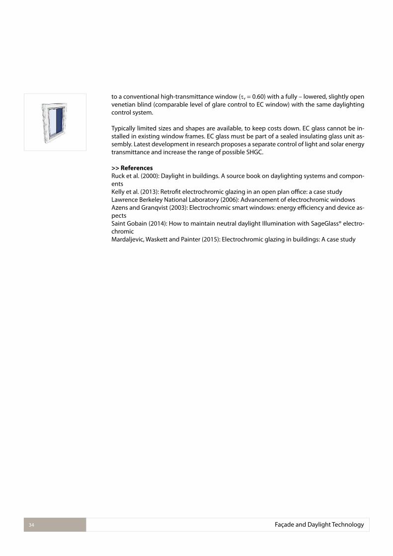
to a conventional high-transmittance window ( v = 0.60) with a fully – lowered, slightly open venetian blind (comparable level of glare control to EC window) with the same daylighting control system.
Typically limited sizes and shapes are available, to keep costs down. EC glass cannot be in-stalled in existing window frames. EC glass must be part of a sealed insulating glass unit as-sembly. Latest development in research proposes a separate control of light and solar energy transmittance and increase the range of possible SHGC.
>> References
Ruck et al. (2000): Daylight in buildings. A source book on daylighting systems and compon-entsKelly et al. (2013): Retroit electrochromic glazing in an open plan oice: a case study Lawrence Berkeley National Laboratory (2006): Advancement of electrochromic windowsAzens and Granqvist (2003): Electrochromic smart windows: energy eiciency and device as-pectsSaint Gobain (2014): How to maintain neutral daylight Illumination with SageGlass® electro-chromicMardaljevic, Waskett and Painter (2015): Electrochromic glazing in buildings: A case study
Façade and Daylight Technology34
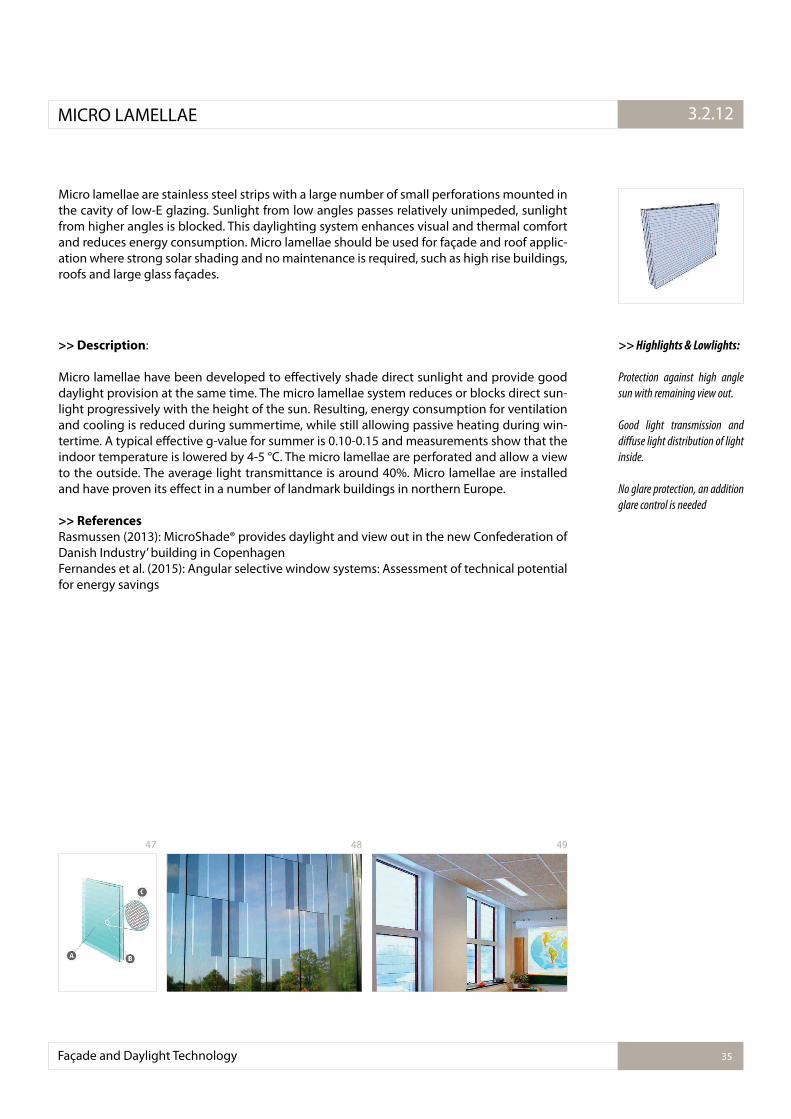
Micro lamellae are stainless steel strips with a large number of small perforations mounted in the cavity of low-E glazing. Sunlight from low angles passes relatively unimpeded, sunlight from higher angles is blocked. This daylighting system enhances visual and thermal comfort and reduces energy consumption. Micro lamellae should be used for façade and roof applic-ation where strong solar shading and no maintenance is required, such as high rise buildings, roofs and large glass façades.
>> Description:
Micro lamellae have been developed to efectively shade direct sunlight and provide good daylight provision at the same time. The micro lamellae system reduces or blocks direct sun-light progressively with the height of the sun. Resulting, energy consumption for ventilation and cooling is reduced during summertime, while still allowing passive heating during win-tertime. A typical efective g-value for summer is 0.10-0.15 and measurements show that the indoor temperature is lowered by 4-5 °C. The micro lamellae are perforated and allow a view to the outside. The average light transmittance is around 40%. Micro lamellae are installed and have proven its efect in a number of landmark buildings in northern Europe.
>> References
Rasmussen (2013): MicroShade® provides daylight and view out in the new Confederation of Danish Industry’ building in CopenhagenFernandes et al. (2015): Angular selective window systems: Assessment of technical potential for energy savings
>> Highlights & Lowlights:
Protection against high angle
sun with remaining view out.
Good light transmission and
difuse light distribution of light
inside.
No glare protection, an addition
glare control is needed
Façade and Daylight Technology 35
3.2.1.MICRO LAMELLAE 3.2.12
47 48 49
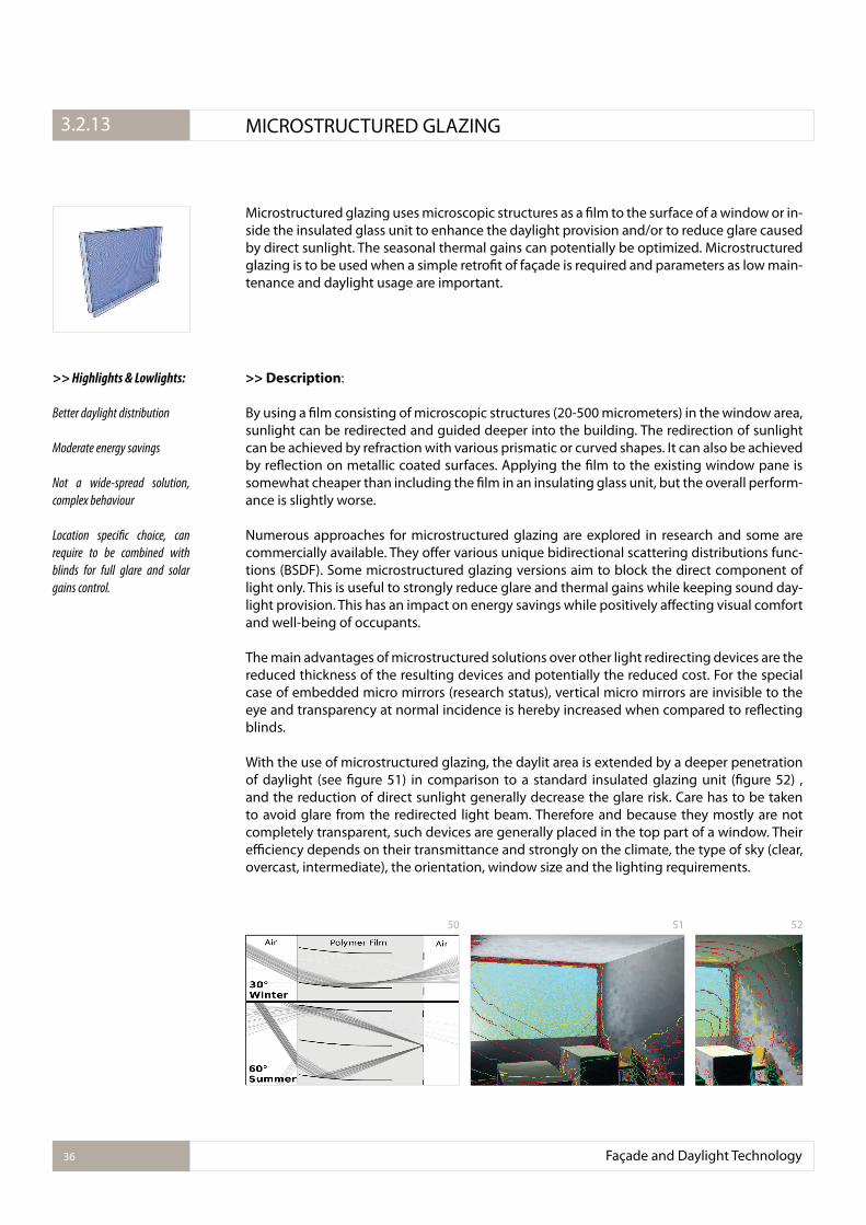
Microstructured glazing uses microscopic structures as a ilm to the surface of a window or in-side the insulated glass unit to enhance the daylight provision and/or to reduce glare caused by direct sunlight. The seasonal thermal gains can potentially be optimized. Microstructured glazing is to be used when a simple retroit of façade is required and parameters as low main-tenance and daylight usage are important.
>> Description:
By using a ilm consisting of microscopic structures (20-500 micrometers) in the window area, sunlight can be redirected and guided deeper into the building. The redirection of sunlight can be achieved by refraction with various prismatic or curved shapes. It can also be achieved by relection on metallic coated surfaces. Applying the ilm to the existing window pane is somewhat cheaper than including the ilm in an insulating glass unit, but the overall perform-ance is slightly worse.
Numerous approaches for microstructured glazing are explored in research and some are commercially available. They ofer various unique bidirectional scattering distributions func-tions (BSDF). Some microstructured glazing versions aim to block the direct component of light only. This is useful to strongly reduce glare and thermal gains while keeping sound day-light provision. This has an impact on energy savings while positively afecting visual comfort and well-being of occupants.
The main advantages of microstructured solutions over other light redirecting devices are the reduced thickness of the resulting devices and potentially the reduced cost. For the special case of embedded micro mirrors (research status), vertical micro mirrors are invisible to the eye and transparency at normal incidence is hereby increased when compared to relecting blinds.
With the use of microstructured glazing, the daylit area is extended by a deeper penetration of daylight (see igure 51) in comparison to a standard insulated glazing unit (igure 52) , and the reduction of direct sunlight generally decrease the glare risk. Care has to be taken to avoid glare from the redirected light beam. Therefore and because they mostly are not completely transparent, such devices are generally placed in the top part of a window. Their eiciency depends on their transmittance and strongly on the climate, the type of sky (clear, overcast, intermediate), the orientation, window size and the lighting requirements.
>> Highlights & Lowlights:
Better daylight distribution
Moderate energy savings
Not a wide-spread solution,
complex behaviour
Location speciic choice, can
require to be combined with
blinds for full glare and solar
gains control.
Façade and Daylight Technology36
3.2.1. MICROSTRUCTURED GLAZING3.2.13
50 51 52
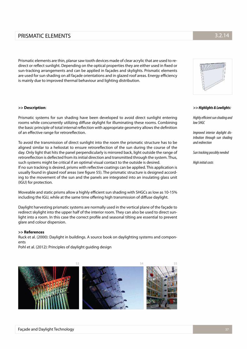
Prismatic elements are thin, planar saw tooth devices made of clear acrylic that are used to re-direct or relect sunlight. Depending on the optical properties they are either used in ixed or sun-tracking arrangements and can be applied in façades and skylights. Prismatic elements are used for sun shading on all façade orientations and in glazed roof areas. Energy eiciency is mainly due to improved thermal behaviour and lighting distribution.
>> Description:
Prismatic systems for sun shading have been developed to avoid direct sunlight entering rooms while concurrently utilizing difuse skylight for illuminating these rooms. Combining the basic principle of total internal relection with appropriate geometry allows the deinition of an efective range for retrorelection.
To avoid the transmission of direct sunlight into the room the prismatic structure has to be aligned similar to a heliostat to ensure retrorelection of the sun during the course of the day. Only light that hits the panel perpendicularly is mirrored back, light outside the range of retrorelection is delected from its initial direction and transmitted through the system. Thus, such systems might be critical if an optimal visual contact to the outside is desired. If no sun tracking is desired, prisms with relective coatings can be applied. This application is usually found in glazed roof areas (see igure 55). The prismatic structure is designed accord-ing to the movement of the sun and the panels are integrated into an insulating glass unit (IGU) for protection.
Moveable and static prisms allow a highly eicient sun shading with SHGCs as low as 10-15% including the IGU, while at the same time ofering high transmission of difuse daylight.
Daylight harvesting prismatic systems are normally used in the vertical plane of the façade to redirect skylight into the upper half of the interior room. They can also be used to direct sun-light into a room. In this case the correct proile and seasonal tilting are essential to prevent glare and colour dispersion.
>> References
Ruck et al. (2000): Daylight in buildings. A source book on daylighting systems and compon-entsPohl et al. (2012): Principles of daylight guiding design
>> Highlights & Lowlights:
Highly e�cient sun shading and
low SHGC
Improved interior daylight dis-
tribution through sun shading
and redirection
Sun tracking possibly needed
High initial costs
Façade and Daylight Technology 37
3.2.1.PRISMATIC ELEMENTS 3.2.14
5553 54
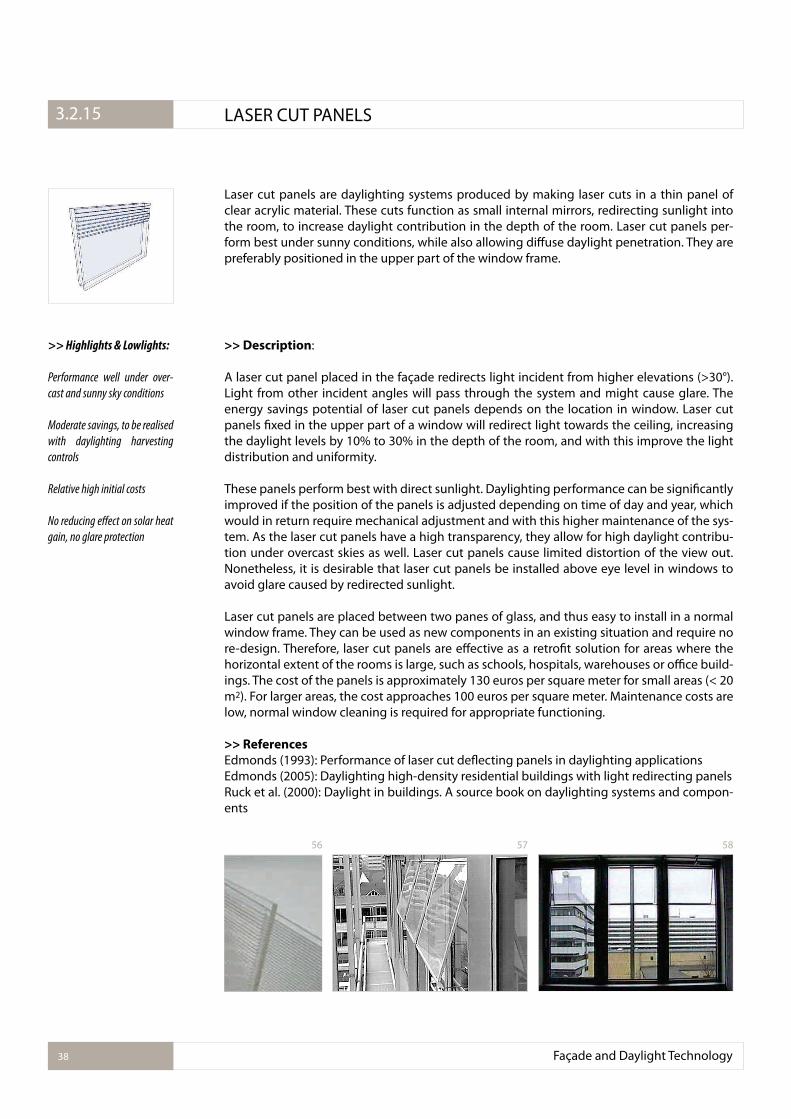
Laser cut panels are daylighting systems produced by making laser cuts in a thin panel of clear acrylic material. These cuts function as small internal mirrors, redirecting sunlight into the room, to increase daylight contribution in the depth of the room. Laser cut panels per-form best under sunny conditions, while also allowing difuse daylight penetration. They are preferably positioned in the upper part of the window frame.
>> Description:
A laser cut panel placed in the façade redirects light incident from higher elevations (>30°). Light from other incident angles will pass through the system and might cause glare. The energy savings potential of laser cut panels depends on the location in window. Laser cut panels ixed in the upper part of a window will redirect light towards the ceiling, increasing the daylight levels by 10% to 30% in the depth of the room, and with this improve the light distribution and uniformity.
These panels perform best with direct sunlight. Daylighting performance can be signiicantly improved if the position of the panels is adjusted depending on time of day and year, which would in return require mechanical adjustment and with this higher maintenance of the sys-tem. As the laser cut panels have a high transparency, they allow for high daylight contribu-tion under overcast skies as well. Laser cut panels cause limited distortion of the view out. Nonetheless, it is desirable that laser cut panels be installed above eye level in windows to avoid glare caused by redirected sunlight.
Laser cut panels are placed between two panes of glass, and thus easy to install in a normal window frame. They can be used as new components in an existing situation and require no re-design. Therefore, laser cut panels are efective as a retroit solution for areas where the horizontal extent of the rooms is large, such as schools, hospitals, warehouses or oice build-ings. The cost of the panels is approximately 130 euros per square meter for small areas (< 20 m2). For larger areas, the cost approaches 100 euros per square meter. Maintenance costs are low, normal window cleaning is required for appropriate functioning.
>> References
Edmonds (1993): Performance of laser cut delecting panels in daylighting applicationsEdmonds (2005): Daylighting high-density residential buildings with light redirecting panelsRuck et al. (2000): Daylight in buildings. A source book on daylighting systems and compon-ents
>> Highlights & Lowlights:
Performance well under over-
cast and sunny sky conditions
Moderate savings, to be realised
with daylighting harvesting
controls
Relative high initial costs
No reducing efect on solar heat
gain, no glare protection
Façade and Daylight Technology38
3.2.1. LASER CUT PANELS3.2.15
57 5856
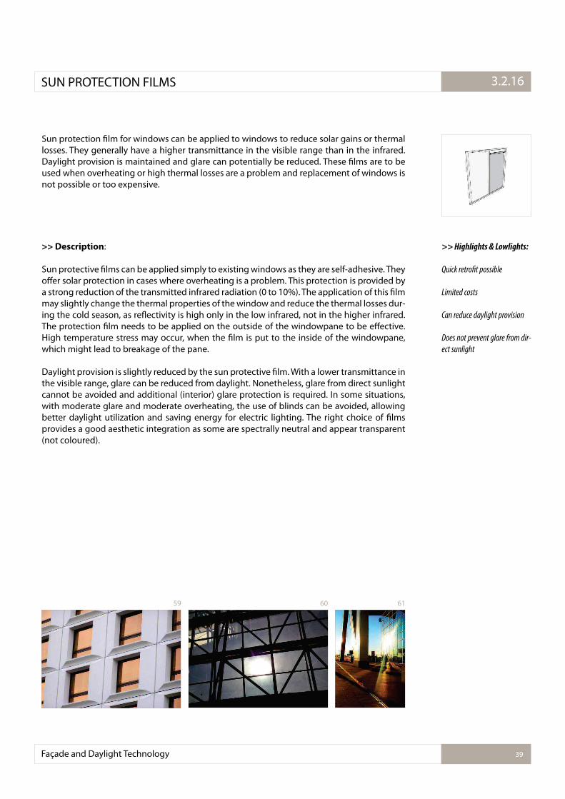
Sun protection ilm for windows can be applied to windows to reduce solar gains or thermal losses. They generally have a higher transmittance in the visible range than in the infrared. Daylight provision is maintained and glare can potentially be reduced. These ilms are to be used when overheating or high thermal losses are a problem and replacement of windows is not possible or too expensive.
>> Description:
Sun protective ilms can be applied simply to existing windows as they are self-adhesive. They ofer solar protection in cases where overheating is a problem. This protection is provided by a strong reduction of the transmitted infrared radiation (0 to 10%). The application of this ilm may slightly change the thermal properties of the window and reduce the thermal losses dur-ing the cold season, as relectivity is high only in the low infrared, not in the higher infrared. The protection ilm needs to be applied on the outside of the windowpane to be efective. High temperature stress may occur, when the ilm is put to the inside of the windowpane, which might lead to breakage of the pane.
Daylight provision is slightly reduced by the sun protective ilm. With a lower transmittance in the visible range, glare can be reduced from daylight. Nonetheless, glare from direct sunlight cannot be avoided and additional (interior) glare protection is required. In some situations, with moderate glare and moderate overheating, the use of blinds can be avoided, allowing better daylight utilization and saving energy for electric lighting. The right choice of ilms provides a good aesthetic integration as some are spectrally neutral and appear transparent (not coloured).
>> Highlights & Lowlights:
Quick retroit possible
Limited costs
Can reduce daylight provision
Does not prevent glare from dir-
ect sunlight
Façade and Daylight Technology 39
3.2.1.SUN PROTECTION FILMS 3.2.16
616059
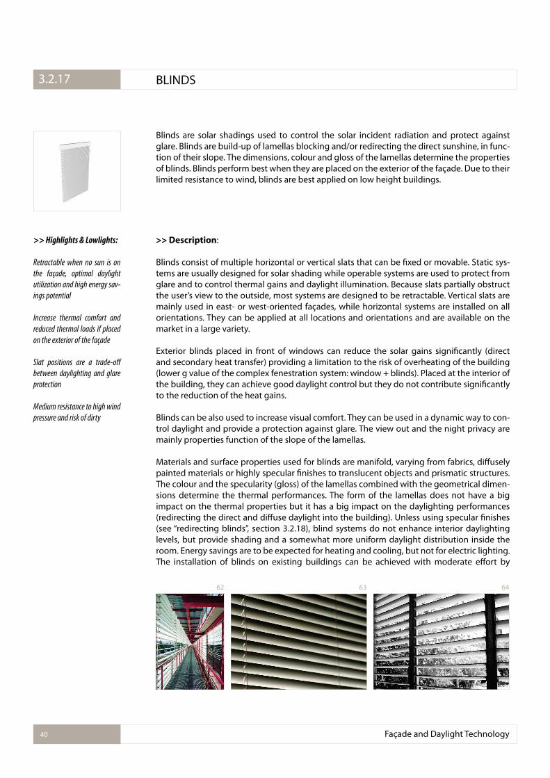
Blinds are solar shadings used to control the solar incident radiation and protect against glare. Blinds are build-up of lamellas blocking and/or redirecting the direct sunshine, in func-tion of their slope. The dimensions, colour and gloss of the lamellas determine the properties of blinds. Blinds perform best when they are placed on the exterior of the façade. Due to their limited resistance to wind, blinds are best applied on low height buildings.
>> Description:
Blinds consist of multiple horizontal or vertical slats that can be ixed or movable. Static sys-tems are usually designed for solar shading while operable systems are used to protect from glare and to control thermal gains and daylight illumination. Because slats partially obstruct the user’s view to the outside, most systems are designed to be retractable. Vertical slats are mainly used in east- or west-oriented façades, while horizontal systems are installed on all orientations. They can be applied at all locations and orientations and are available on the market in a large variety.
Exterior blinds placed in front of windows can reduce the solar gains signiicantly (direct and secondary heat transfer) providing a limitation to the risk of overheating of the building (lower g value of the complex fenestration system: window + blinds). Placed at the interior of the building, they can achieve good daylight control but they do not contribute signiicantly to the reduction of the heat gains.
Blinds can be also used to increase visual comfort. They can be used in a dynamic way to con-trol daylight and provide a protection against glare. The view out and the night privacy are mainly properties function of the slope of the lamellas.
Materials and surface properties used for blinds are manifold, varying from fabrics, difusely painted materials or highly specular inishes to translucent objects and prismatic structures. The colour and the specularity (gloss) of the lamellas combined with the geometrical dimen-sions determine the thermal performances. The form of the lamellas does not have a big impact on the thermal properties but it has a big impact on the daylighting performances (redirecting the direct and difuse daylight into the building). Unless using specular inishes (see “redirecting blinds”, section 3.2.18), blind systems do not enhance interior daylighting levels, but provide shading and a somewhat more uniform daylight distribution inside the room. Energy savings are to be expected for heating and cooling, but not for electric lighting.The installation of blinds on existing buildings can be achieved with moderate efort by
>> Highlights & Lowlights:
Retractable when no sun is on
the façade, optimal daylight
utilization and high energy sav-
ings potential
Increase thermal comfort and
reduced thermal loads if placed
on the exterior of the façade
Slat positions are a trade-of
between daylighting and glare
protection
Medium resistance to high wind
pressure and risk of dirty
Façade and Daylight Technology40
3.2.1. BLINDS3.2.17
63 6462
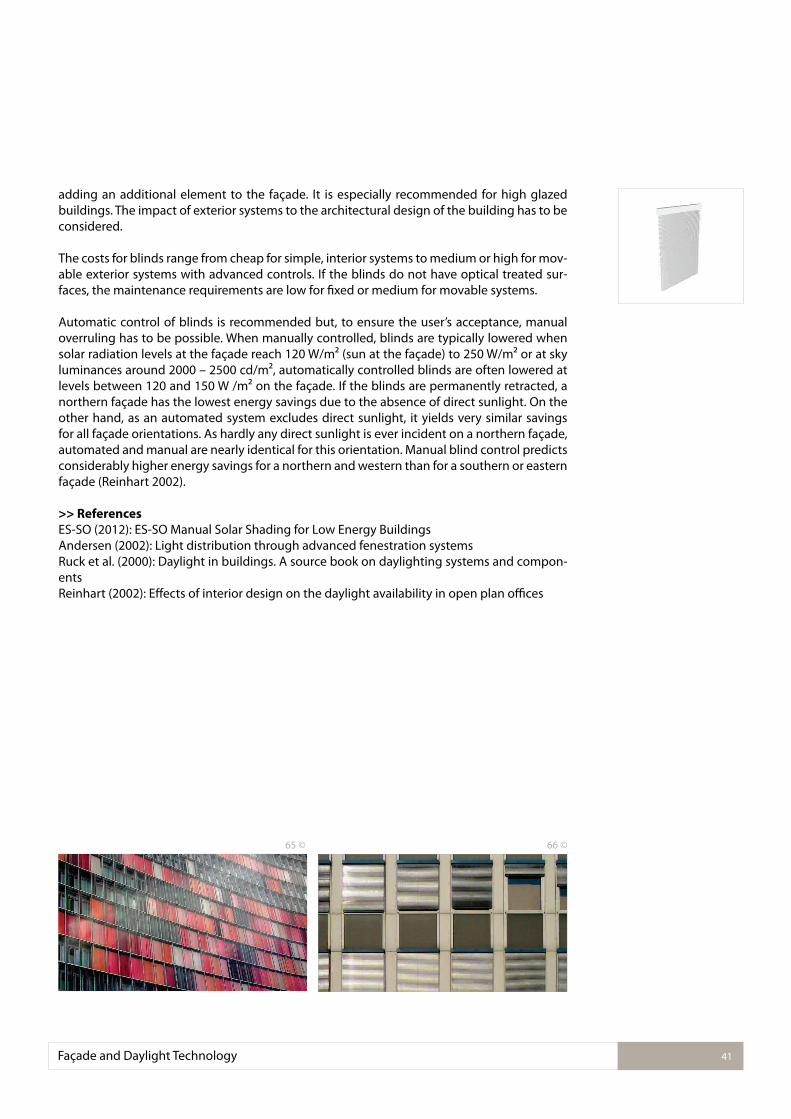
adding an additional element to the façade. It is especially recommended for high glazed buildings. The impact of exterior systems to the architectural design of the building has to be considered.
The costs for blinds range from cheap for simple, interior systems to medium or high for mov-able exterior systems with advanced controls. If the blinds do not have optical treated sur-faces, the maintenance requirements are low for ixed or medium for movable systems.
Automatic control of blinds is recommended but, to ensure the user’s acceptance, manual overruling has to be possible. When manually controlled, blinds are typically lowered when solar radiation levels at the façade reach 120 W/m² (sun at the façade) to 250 W/m² or at sky luminances around 2000 – 2500 cd/m², automatically controlled blinds are often lowered at levels between 120 and 150 W /m² on the façade. If the blinds are permanently retracted, a northern façade has the lowest energy savings due to the absence of direct sunlight. On the other hand, as an automated system excludes direct sunlight, it yields very similar savings for all façade orientations. As hardly any direct sunlight is ever incident on a northern façade, automated and manual are nearly identical for this orientation. Manual blind control predicts considerably higher energy savings for a northern and western than for a southern or eastern façade (Reinhart 2002).
>> References
ES-SO (2012): ES-SO Manual Solar Shading for Low Energy BuildingsAndersen (2002): Light distribution through advanced fenestration systemsRuck et al. (2000): Daylight in buildings. A source book on daylighting systems and compon-entsReinhart (2002): Efects of interior design on the daylight availability in open plan oices
Façade and Daylight Technology 41
65 © 66 ©
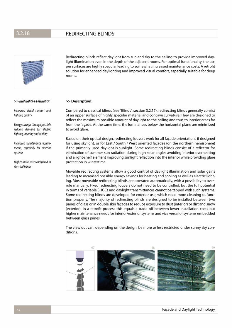
Redirecting blinds relect daylight from sun and sky to the ceiling to provide improved day-light illumination even in the depth of the adjacent rooms. For optimal functionality, the up-per surfaces are highly specular leading to somewhat increased maintenance costs. A retroit solution for enhanced daylighting and improved visual comfort, especially suitable for deep rooms.
Façade and Daylight Technology42
3.2.1. REDIRECTING BLINDS3.2.18
>> Description:
Compared to classical blinds (see “Blinds”, section 3.2.17), redirecting blinds generally consist of an upper surface of highly specular material and concave curvature. They are designed to relect the maximum possible amount of daylight to the ceiling and thus to interior areas far from the façade. At the same time, the luminances below the horizontal plane are minimized to avoid glare.
Based on their optical design, redirecting louvers work for all façade orientations if designed for using skylight, or for East / South / West oriented façades (on the northern hemisphere) if the primarily used daylight is sunlight. Some redirecting blinds consist of a relector for elimination of summer sun radiation during high solar angles avoiding interior overheating and a light-shelf element improving sunlight relection into the interior while providing glare protection in wintertime.
Movable redirecting systems allow a good control of daylight illumination and solar gains leading to increased possible energy savings for heating and cooling as well as electric light-ing. Most moveable redirecting blinds are operated automatically, with a possibility to over-rule manually. Fixed redirecting louvers do not need to be controlled, but the full potential in terms of variable SHGCs and daylight transmittances cannot be tapped with such systems. Some redirecting blinds are developed for exterior use, which need more cleaning to func-tion properly. The majority of redirecting blinds are designed to be installed between two panes of glass or in double skin façades to reduce exposure to dust (interior) or dirt and snow (exterior). In a retroit process this equals a trade-of between lower installation costs but higher maintenance needs for interior/exterior systems and vice versa for systems embedded between glass panes.
The view out can, depending on the design, be more or less restricted under sunny sky con-ditions.
>> Highlights & Lowlights:
Increased visual comfort and
lighting quality
Energy savings through possible
reduced demand for electric
lighting, heating and cooling
Increased maintenance require-
ments, especially for exterior
systems
Higher initial costs compared to
classical blinds
68 6967
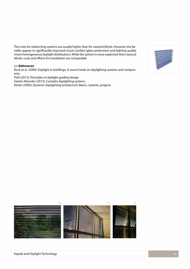
The costs for redirecting systems are usually higher than for classical blinds. However, the be-neits appear in signiicantly improved visual comfort (glare protection) and lighting quality (more homogeneous daylight distribution). While the system is more expensive than classical blinds, costs and eforts for installation are comparable.
>> References
Ruck et al. (2000): Daylight in buildings. A source book on daylighting systems and compon-entsPohl (2012): Principles of daylight guiding designGeisler-Moroder (2013): Complex daylighting systemsKöster (2004): Dynamic Daylighting architecture: Basics, systems, projects
Façade and Daylight Technology 43
7270 71
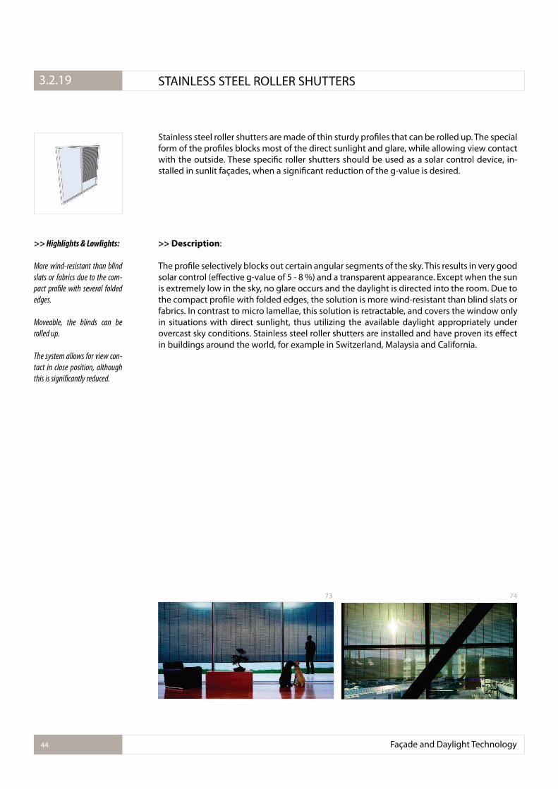
Stainless steel roller shutters are made of thin sturdy proiles that can be rolled up. The special form of the proiles blocks most of the direct sunlight and glare, while allowing view contact with the outside. These speciic roller shutters should be used as a solar control device, in-stalled in sunlit façades, when a signiicant reduction of the g-value is desired.
>> Description:
The proile selectively blocks out certain angular segments of the sky. This results in very good solar control (efective g-value of 5 - 8 %) and a transparent appearance. Except when the sun is extremely low in the sky, no glare occurs and the daylight is directed into the room. Due to the compact proile with folded edges, the solution is more wind-resistant than blind slats or fabrics. In contrast to micro lamellae, this solution is retractable, and covers the window only in situations with direct sunlight, thus utilizing the available daylight appropriately under overcast sky conditions. Stainless steel roller shutters are installed and have proven its efect in buildings around the world, for example in Switzerland, Malaysia and California.
>> Highlights & Lowlights:
More wind-resistant than blind
slats or fabrics due to the com-
pact proile with several folded
edges.
Moveable, the blinds can be
rolled up.
The system allows for view con-
tact in close position, although
this is signiicantly reduced.
Façade and Daylight Technology44
3.2.1. STAINLESS STEEL ROLLER SHUTTERS3.2.19
73 74
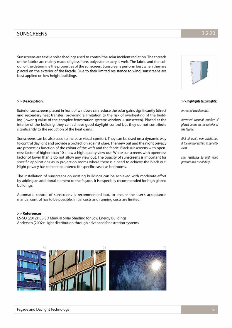
Sunscreens are textile solar shadings used to control the solar incident radiation. The threads of the fabrics are mainly made of glass ibre, polyester or acrylic weft. The fabric and the col-our of the determine the properties of the sunscreen. Sunscreens perform best when they are placed on the exterior of the façade. Due to their limited resistance to wind, sunscreens are best applied on low height buildings.
>> Description:
Exterior sunscreens placed in front of windows can reduce the solar gains signiicantly (direct and secondary heat transfer) providing a limitation to the risk of overheating of the build-ing (lower g value of the complex fenestration system: window + sunscreen). Placed at the interior of the building, they can achieve good daylight control but they do not contribute signiicantly to the reduction of the heat gains.
Sunscreens can be also used to increase visual comfort. They can be used on a dynamic way to control daylight and provide a protection against glare. The view out and the night privacy are properties function of the colour of the weft and the fabric. Black sunscreens with open-ness factor of higher than 10 allow a high quality view out. White sunscreens with openness factor of lower than 3 do not allow any view out. The opacity of sunscreens is important for speciic applications as in projection rooms where there is a need to achieve the black out. Night privacy has to be encountered for speciic cases as bedrooms.
The installation of sunscreens on existing buildings can be achieved with moderate efort by adding an additional element to the façade. It is especially recommended for high glazed buildings.
Automatic control of sunscreens is recommended but, to ensure the user’s acceptance, manual control has to be possible. Initial costs and running costs are limited.
>> References
ES-SO (2012): ES-SO Manual Solar Shading for Low Energy BuildingsAndersen (2002): Light distribution through advanced fenestration systems
>> Highlights & Lowlights:
Increased visual comfort
Increased thermal comfort if
placed on the on the exterior of
the façade.
Risk of user’s non-satisfaction
if the control system is not e�-
cient
Low resistance to high wind
pressure and risk of dirty
Façade and Daylight Technology 45
3.2.1.SUNSCREENS 3.2.20
75 76 77
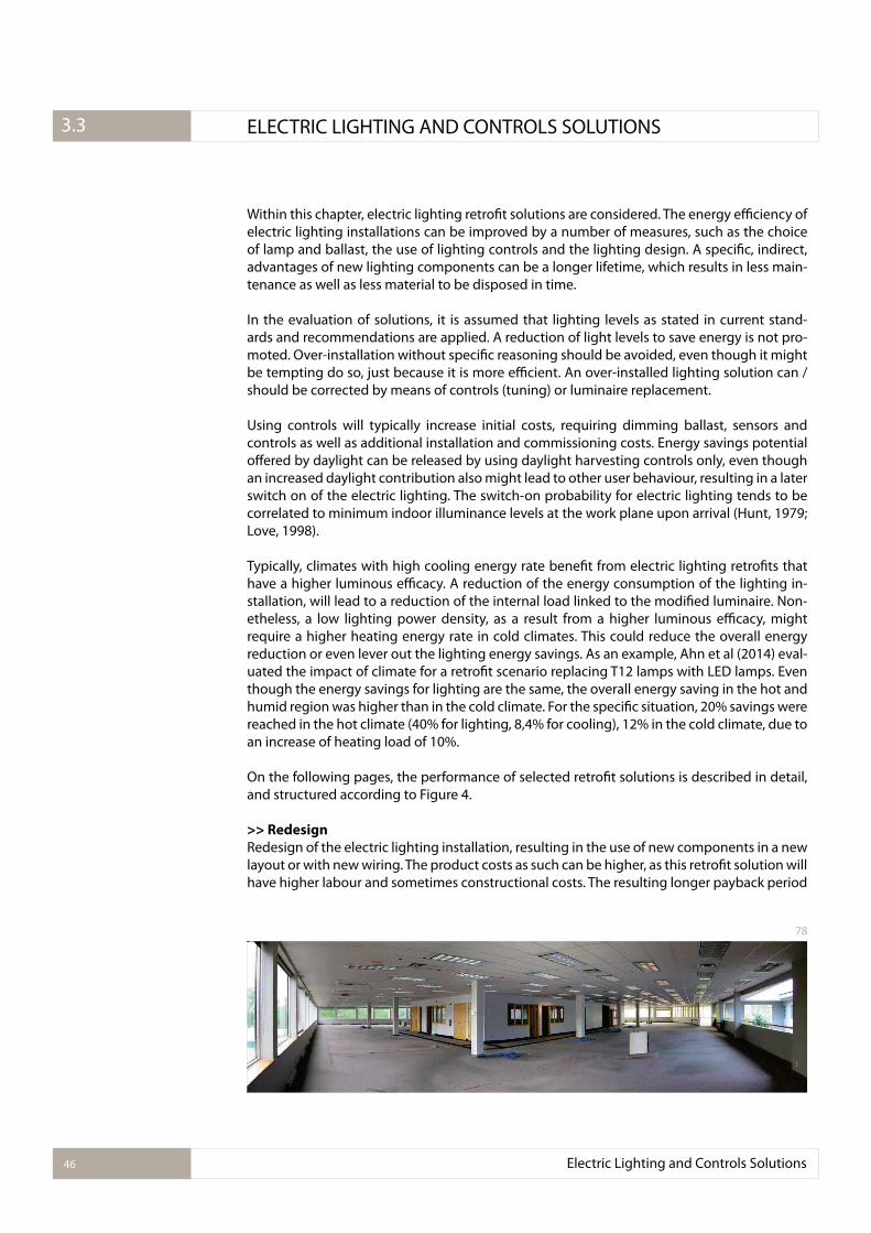
Within this chapter, electric lighting retroit solutions are considered. The energy eiciency of electric lighting installations can be improved by a number of measures, such as the choice of lamp and ballast, the use of lighting controls and the lighting design. A speciic, indirect, advantages of new lighting components can be a longer lifetime, which results in less main-tenance as well as less material to be disposed in time.
In the evaluation of solutions, it is assumed that lighting levels as stated in current stand-ards and recommendations are applied. A reduction of light levels to save energy is not pro-moted. Over-installation without speciic reasoning should be avoided, even though it might be tempting do so, just because it is more eicient. An over-installed lighting solution can / should be corrected by means of controls (tuning) or luminaire replacement.
Using controls will typically increase initial costs, requiring dimming ballast, sensors and controls as well as additional installation and commissioning costs. Energy savings potential ofered by daylight can be released by using daylight harvesting controls only, even though an increased daylight contribution also might lead to other user behaviour, resulting in a later switch on of the electric lighting. The switch-on probability for electric lighting tends to be correlated to minimum indoor illuminance levels at the work plane upon arrival (Hunt, 1979; Love, 1998).
Typically, climates with high cooling energy rate beneit from electric lighting retroits that have a higher luminous eicacy. A reduction of the energy consumption of the lighting in-stallation, will lead to a reduction of the internal load linked to the modiied luminaire. Non-etheless, a low lighting power density, as a result from a higher luminous eicacy, might require a higher heating energy rate in cold climates. This could reduce the overall energy reduction or even lever out the lighting energy savings. As an example, Ahn et al (2014) eval-uated the impact of climate for a retroit scenario replacing T12 lamps with LED lamps. Even though the energy savings for lighting are the same, the overall energy saving in the hot and humid region was higher than in the cold climate. For the speciic situation, 20% savings were reached in the hot climate (40% for lighting, 8,4% for cooling), 12% in the cold climate, due to an increase of heating load of 10%.
On the following pages, the performance of selected retroit solutions is described in detail, and structured according to Figure 4.
>> Redesign
Redesign of the electric lighting installation, resulting in the use of new components in a new layout or with new wiring. The product costs as such can be higher, as this retroit solution will have higher labour and sometimes constructional costs. The resulting longer payback period
Electric Lighting and Controls Solutions46
3.2.1. ELECTRIC LIGHTING AND CONTROLS SOLUTIONS3.3
78
for these retroit solutions might be balanced out by the inancial, human-performance and psychological beneits of a lighting condition with a higher quality.
Retroit technologies: task-ambient lighting, algorithmic lighting, virtual windows, demand driven lighting controls, daylight responsive lighting controls (Section 3.3.1 - 3.3.5)
>> Use of new components
Replacing a luminaire with one that has diferent characteristics, typically increasing energy eiciency, due to an improvement of light source or ballast technology that requires a new luminaire, or due to an improvement in luminaire technology. Adding luminaires with lu-minaire based controls, such as sensors for presence sensing, daylight dimming or personal control.
Retroit technologies: daylight responsive lighting controls - luminaire based, occupancy sensing - luminaire based, personal control, LED retroits for CFL downlights, LED luminaire replacements (Section 3.3.5 - 3.3.10)
>> Upgrade of existing situation
Replacing a component within the electric lighting installation, such as a lamp by a light source with improved eiciency, spectral quality or increased luminous lux, or a magnatic ballast by an electronic ballast. Adding stand-alone controls, such as a time switch to reduce total switch-on time, wireless sensors, or sensors for presence sensing that allow switching of luminaires only.
Retroit technologies: occupancy sensing - room based, personal control through switches, time scheduling, wireless controls, electronic ballasts, luorescent lamp replacements, LED replacements for halogen and incandescent lamps, LED T8 replacement lamps (Section 3.3.9 - 3.3.16)
Electric Lighting and Controls Solutions 47
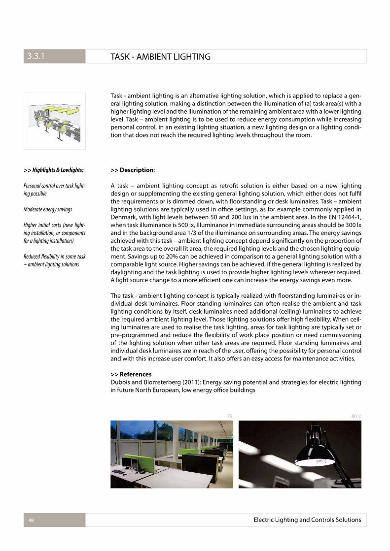
Task - ambient lighting is an alternative lighting solution, which is applied to replace a gen-eral lighting solution, making a distinction between the illumination of (a) task area(s) with a higher lighting level and the illumination of the remaining ambient area with a lower lighting level. Task – ambient lighting is to be used to reduce energy consumption while increasing personal control, in an existing lighting situation, a new lighting design or a lighting condi-tion that does not reach the required lighting levels throughout the room.
>> Description:
A task – ambient lighting concept as retroit solution is either based on a new lighting design or supplementing the existing general lighting solution, which either does not fulil the requirements or is dimmed down, with loorstanding or desk luminaires. Task – ambient lighting solutions are typically used in oice settings, as for example commonly applied in Denmark, with light levels between 50 and 200 lux in the ambient area. In the EN 12464-1, when task illuminance is 500 lx, Illuminance in immediate surrounding areas should be 300 lx and in the background area 1/3 of the illuminance on surrounding areas. The energy savings achieved with this task – ambient lighting concept depend signiicantly on the proportion of the task area to the overall lit area, the required lighting levels and the chosen lighting equip-ment. Savings up to 20% can be achieved in comparison to a general lighting solution with a comparable light source. Higher savings can be achieved, if the general lighting is realized by daylighting and the task lighting is used to provide higher lighting levels wherever required. A light source change to a more eicient one can increase the energy savings even more.
The task - ambient lighting concept is typically realized with loorstanding luminaires or in-dividual desk luminaires. Floor standing luminaires can often realise the ambient and task lighting conditions by itself, desk luminaires need additional (ceiling) luminaires to achieve the required ambient lighting level. Those lighting solutions ofer high lexibility. When ceil-ing luminaires are used to realise the task lighting, areas for task lighting are typically set or pre-programmed and reduce the lexibility of work place position or need commissioning of the lighting solution when other task areas are required. Floor standing luminaires and individual desk luminaires are in reach of the user, ofering the possibility for personal control and with this increase user comfort. It also ofers an easy access for maintenance activities.
>> References
Dubois and Blomsterberg (2011): Energy saving potential and strategies for electric lighting in future North European, low energy oice buildings
>> Highlights & Lowlights:
Personal control over task light-
ing possible
Moderate energy savings
Higher initial costs (new light-
ing installation, or components
for a lighting installation)
Reduced lexibility in some task
– ambient lighting solutions
Electric Lighting and Controls Solutions48
3.2.1. TASK - AMBIENT LIGHTING3.3.1
79 80 ©
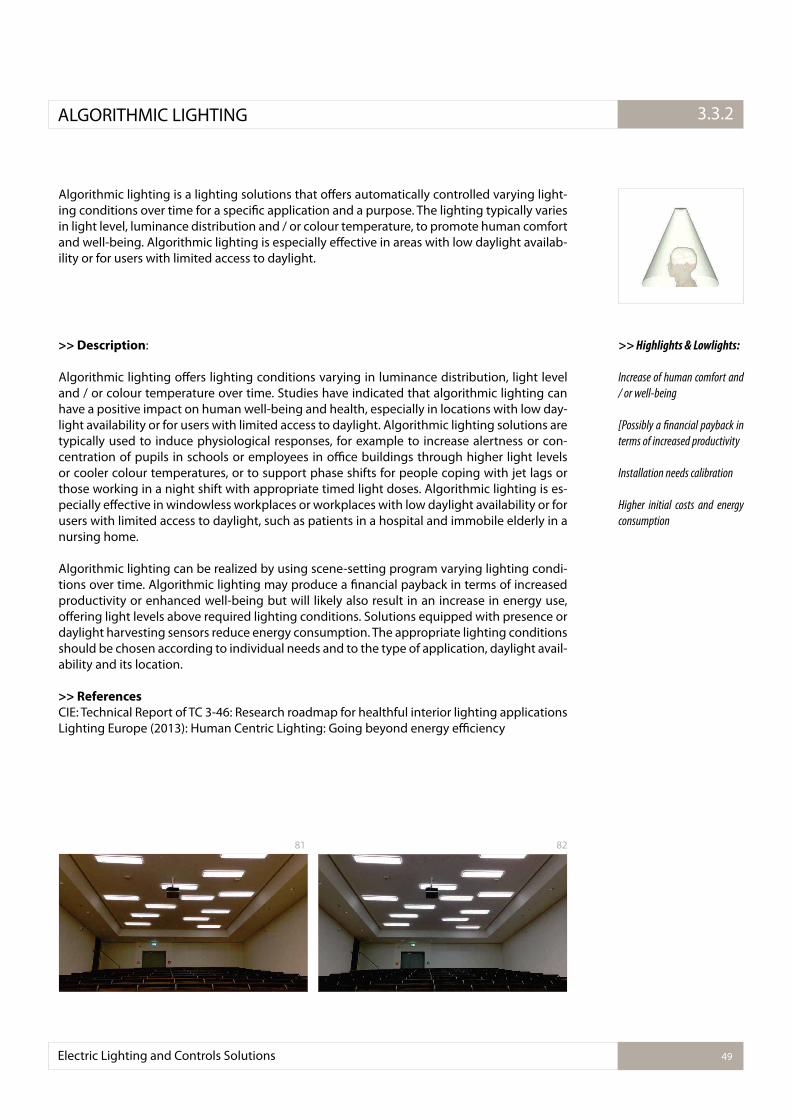
Algorithmic lighting is a lighting solutions that ofers automatically controlled varying light-ing conditions over time for a speciic application and a purpose. The lighting typically varies in light level, luminance distribution and / or colour temperature, to promote human comfort and well-being. Algorithmic lighting is especially efective in areas with low daylight availab-ility or for users with limited access to daylight.
>> Description:
Algorithmic lighting ofers lighting conditions varying in luminance distribution, light level and / or colour temperature over time. Studies have indicated that algorithmic lighting can have a positive impact on human well-being and health, especially in locations with low day-light availability or for users with limited access to daylight. Algorithmic lighting solutions are typically used to induce physiological responses, for example to increase alertness or con-centration of pupils in schools or employees in oice buildings through higher light levels or cooler colour temperatures, or to support phase shifts for people coping with jet lags or those working in a night shift with appropriate timed light doses. Algorithmic lighting is es-pecially efective in windowless workplaces or workplaces with low daylight availability or for users with limited access to daylight, such as patients in a hospital and immobile elderly in a nursing home.
Algorithmic lighting can be realized by using scene-setting program varying lighting condi-tions over time. Algorithmic lighting may produce a inancial payback in terms of increased productivity or enhanced well-being but will likely also result in an increase in energy use, ofering light levels above required lighting conditions. Solutions equipped with presence or daylight harvesting sensors reduce energy consumption. The appropriate lighting conditions should be chosen according to individual needs and to the type of application, daylight avail-ability and its location.
>> References
CIE: Technical Report of TC 3-46: Research roadmap for healthful interior lighting applications Lighting Europe (2013): Human Centric Lighting: Going beyond energy eiciency
>> Highlights & Lowlights:
Increase of human comfort and
/ or well-being
[Possibly a inancial payback in
terms of increased productivity
Installation needs calibration
Higher initial costs and energy
consumption
Electric Lighting and Controls Solutions 49
3.2.1.ALGORITHMIC LIGHTING 3.3.2
81 82
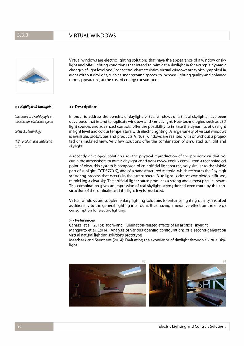
Virtual windows are electric lighting solutions that have the appearance of a window or sky light and ofer lighting conditions that intend to mimic the daylight in for example dynamic changes of light level and / or spectral characteristics. Virtual windows are typically applied in areas without daylight, such as underground spaces, to increase lighting quality and enhance room appearance, at the cost of energy consumption.
>> Description:
In order to address the beneits of daylight, virtual windows or artiicial skylights have been developed that intend to replicate windows and / or daylight. New technologies, such as LED light sources and advanced controls, ofer the possibility to imitate the dynamics of daylight in light level and colour temperature with electric lighting. A large variety of virtual windows is available, prototypes and products. Virtual windows are realised with or without a projec-ted or simulated view. Very few solutions ofer the combination of simulated sunlight and skylight.
A recently developed solution uses the physical reproduction of the phenomena that oc-cur in the atmosphere to mimic daylight conditions (www.coelux.com). From a technological point of view, this system is composed of an artiicial light source, very similar to the visible part of sunlight (CCT 5770 K), and of a nanostructured material which recreates the Rayleigh scattering process that occurs in the atmosphere. Blue light is almost completely difused, mimicking a clear sky. The artiicial light source produces a strong and almost parallel beam. This combination gives an impression of real skylight, strengthened even more by the con-struction of the luminaire and the light levels produced.
Virtual windows are supplementary lighting solutions to enhance lighting quality, installed additionally to the general lighting in a room, thus having a negative efect on the energy consumption for electric lighting.
>> References
Canazei et al. (2015): Room-and illumination-related efects of an artiicial skylightMangkuto et al. (2014): Analysis of various opening conigurations of a second-generation virtual natural lighting solutions prototypeMeerbeek and Seuntiens (2014): Evaluating the experience of daylight through a virtual sky-light
>> Highlights & Lowlights:
Impression of a real daylight at-
mosphere in windowless spaces
Latest LED technology
High product and installation
costs
Electric Lighting and Controls Solutions50
3.2.1. VIRTUAL WINDOWS3.3.3
83 84
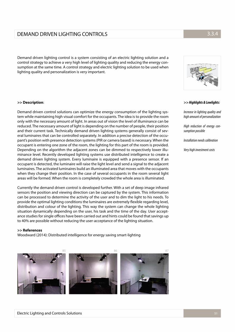
Demand driven lighting control is a system consisting of an electric lighting solution and a control strategy to achieve a very high level of lighting quality and reducing the energy con-sumption at the same time. A control strategy and electric lighting solution to be used when lighting quality and personalization is very important.
>> Description:
Demand driven control solutions can optimize the energy consumption of the lighting sys-tem while maintaining high visual comfort for the occupants. The idea is to provide the room only with the necessary amount of light. In areas out of vision the level of illuminance can be reduced. The necessary amount of light is depending on the number of people, their position and their current task. Technically demand driven lighting systems generally consist of sev-eral luminaires that can be controlled separately. In addition a precise detection of the occu-pant’s position with presence detection systems (PIR or camera based) is necessary. When the occupant is entering one zone of the room, the lighting for this part of the room is provided. Depending on the algorithm the adjacent zones can be dimmed to respectively lower illu-minance level. Recently developed lighting systems use distributed intelligence to create a demand driven lighting system. Every luminaire is equipped with a presence sensor. If an occupant is detected, the luminaire will raise the light level and send a signal to the adjacent luminaires. The activated luminaires build an illuminated area that moves with the occupants when they change their position. In the case of several occupants in the room several light areas will be formed. When the room is completely crowded the whole area is illuminated.
Currently the demand driven control is developed further. With a set of deep image infrared sensors the position and viewing direction can be captured by the system. This information can be processed to determine the activity of the user and to dim the light to his needs. To provide the optimal lighting conditions the luminaires are extremely lexible regarding level, distribution and colour of the lighting. This way the system can change the whole lighting situation dynamically depending on the user, his task and the time of the day. User accept-ance studies for single oices have been carried out and hints could be found that savings up to 40% are possible without reducing the user-acceptance of the lighting situation.
>> References
Woodward (2014): Distributed intelligence for energy saving smart-lighting
>> Highlights & Lowlights:
Increase in lighting quality and
high amount of personalization
High reduction of energy con-
sumption possible
Installation needs calibration
Very high investment costs
Electric Lighting and Controls Solutions 51
3.2.1.DEMAND DRIVEN LIGHTING CONTROLS 3.3.4
8785 86
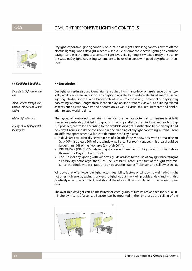
Daylight responsive lighting controls, or so-called daylight harvesting controls, switch of the electric lighting when daylight reaches a set value or dims the electric lighting to combine daylight and electric light to a constant light level. The lighting is switched on by the user or the system. Daylight harvesting systems are to be used in areas with good daylight contribu-tion.
>> Description:
Daylight harvesting is used to maintain a required illuminance level on a reference plane (typ-ically workplace area) in response to daylight availability to reduce electrical energy use for lighting. Studies show a large bandwidth of 20 – 70% for savings potential of daylighting harvesting systems. Geographical location plays an important role as well as building related aspects, such as window size and orientation, as well as visual task requirements and applic-ation related working time.
The layout of controlled luminaires inluences the savings potential. Luminaires in side-lit spaces are preferably divided into groups running parallel to the windows, and each group is, if possible, controlled according to the available daylight. A distinction between daylit and non-daylit zones should be considered in the planning of daylight harvesting systems. There are diferent approaches available to determine the daylit area: » a daylit area will typically lie within 6 m of a façade if the window area with normal glazing
( v > 70%) is at least 20% of the window wall area. For roof-lit spaces, this area should be larger than 10% of the loor area (Littlefair 2014).
» DIN V18599 (DIN 2007) deines daylit areas with medium to high savings potentials as those with a Daylight Factor > 2%.
» The ‘Tips for daylighting with windows’ guide advices to the use of daylight harvesting at a Feasibility Factor larger than 0.25. The Feasibility Factor is the sum of the light transmit-tance, the window to wall ratio and an obstruction factor (Robinson and Selkowitz 2013).
Windows that ofer lower daylight factors, feasibility factors or window to wall ratios might not ofer high energy savings for electric lighting, but likely will provide a view and with this positively afect user comfort, and should therefore still be considered in the redesign pro-cess.
The available daylight can be measured for each group of luminaires or each individual lu-minaire by means of a sensor. Sensors can be mounted in the lamp or at the ceiling of the
>> Highlights & Lowlights:
Moderate to high energy sav-
ings
Higher savings through com-
bination with personal control
possible
Relative high initial costs
Redesign of the lighting install-
ation required
Electric Lighting and Controls Solutions52
3.2.1. DAYLIGHT RESPONSIVE LIGHTING CONTROLS3.3.5
88
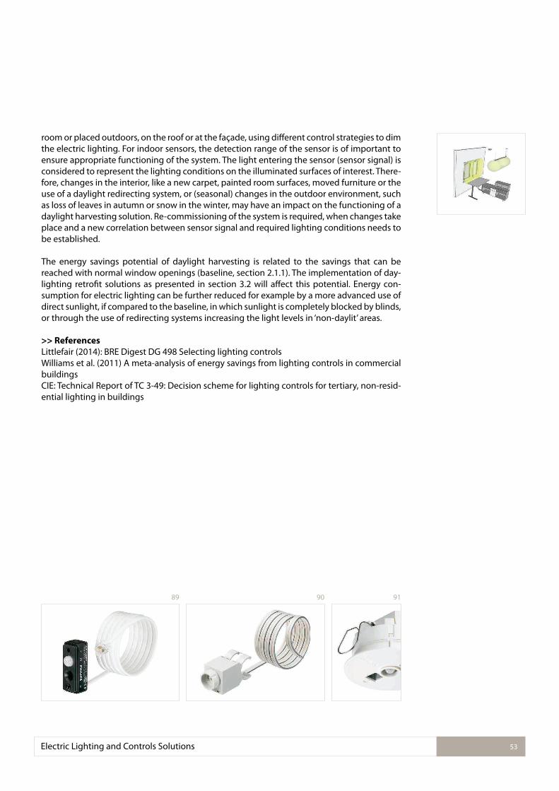
Electric Lighting and Controls Solutions 53
room or placed outdoors, on the roof or at the façade, using diferent control strategies to dim the electric lighting. For indoor sensors, the detection range of the sensor is of important to ensure appropriate functioning of the system. The light entering the sensor (sensor signal) is considered to represent the lighting conditions on the illuminated surfaces of interest. There-fore, changes in the interior, like a new carpet, painted room surfaces, moved furniture or the use of a daylight redirecting system, or (seasonal) changes in the outdoor environment, such as loss of leaves in autumn or snow in the winter, may have an impact on the functioning of a daylight harvesting solution. Re-commissioning of the system is required, when changes take place and a new correlation between sensor signal and required lighting conditions needs to be established.
The energy savings potential of daylight harvesting is related to the savings that can be reached with normal window openings (baseline, section 2.1.1). The implementation of day-lighting retroit solutions as presented in section 3.2 will afect this potential. Energy con-sumption for electric lighting can be further reduced for example by a more advanced use of direct sunlight, if compared to the baseline, in which sunlight is completely blocked by blinds, or through the use of redirecting systems increasing the light levels in ‘non-daylit’ areas. >> References
Littlefair (2014): BRE Digest DG 498 Selecting lighting controlsWilliams et al. (2011) A meta-analysis of energy savings from lighting controls in commercial buildingsCIE: Technical Report of TC 3-49: Decision scheme for lighting controls for tertiary, non-resid-ential lighting in buildings
9189 90
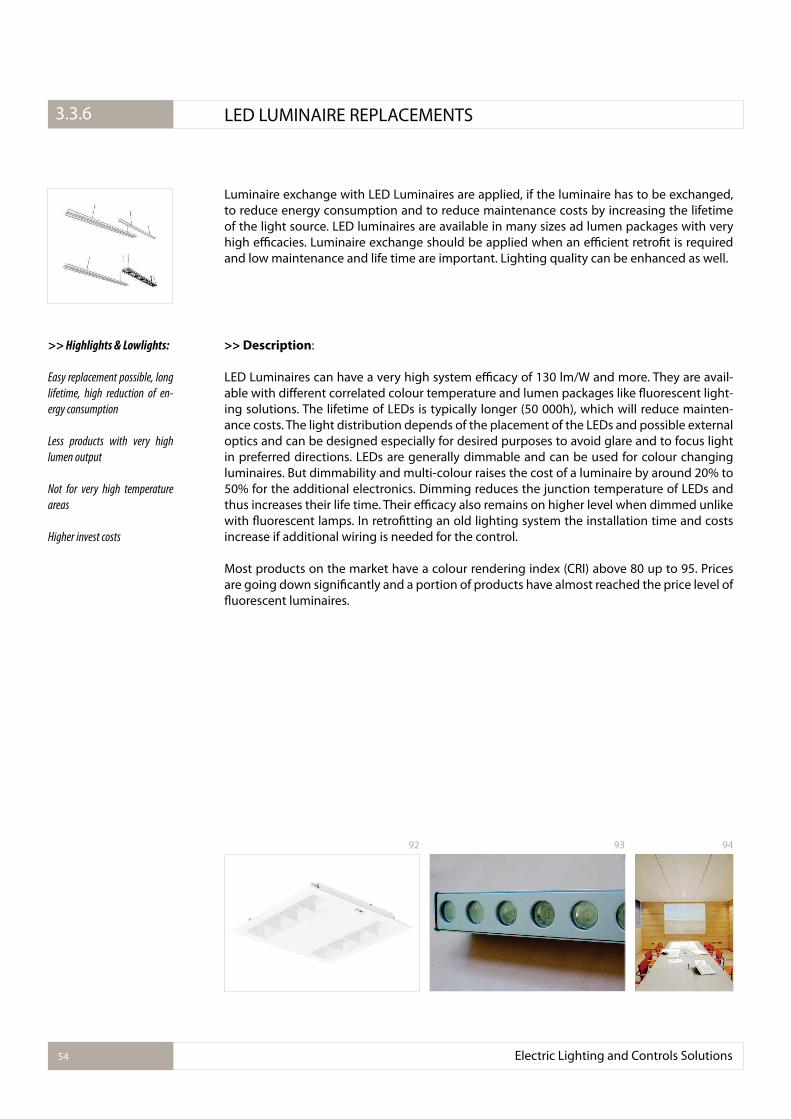
Luminaire exchange with LED Luminaires are applied, if the luminaire has to be exchanged, to reduce energy consumption and to reduce maintenance costs by increasing the lifetime of the light source. LED luminaires are available in many sizes ad lumen packages with very high eicacies. Luminaire exchange should be applied when an eicient retroit is required and low maintenance and life time are important. Lighting quality can be enhanced as well.
>> Description:
LED Luminaires can have a very high system eicacy of 130 lm/W and more. They are avail-able with diferent correlated colour temperature and lumen packages like luorescent light-ing solutions. The lifetime of LEDs is typically longer (50 000h), which will reduce mainten-ance costs. The light distribution depends of the placement of the LEDs and possible external optics and can be designed especially for desired purposes to avoid glare and to focus light in preferred directions. LEDs are generally dimmable and can be used for colour changing luminaires. But dimmability and multi-colour raises the cost of a luminaire by around 20% to 50% for the additional electronics. Dimming reduces the junction temperature of LEDs and thus increases their life time. Their eicacy also remains on higher level when dimmed unlike with luorescent lamps. In retroitting an old lighting system the installation time and costs increase if additional wiring is needed for the control.
Most products on the market have a colour rendering index (CRI) above 80 up to 95. Prices are going down signiicantly and a portion of products have almost reached the price level of luorescent luminaires.
>> Highlights & Lowlights:
Easy replacement possible, long
lifetime, high reduction of en-
ergy consumption
Less products with very high
lumen output
Not for very high temperature
areas
Higher invest costs
Electric Lighting and Controls Solutions54
3.2.1. LED LUMINAIRE REPLACEMENTS3.3.6
92 93 94
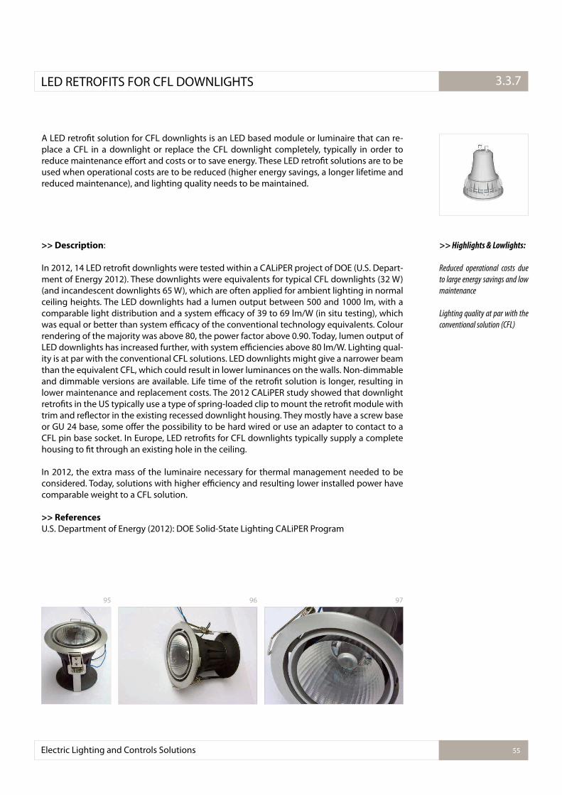
A LED retroit solution for CFL downlights is an LED based module or luminaire that can re-place a CFL in a downlight or replace the CFL downlight completely, typically in order to reduce maintenance efort and costs or to save energy. These LED retroit solutions are to be used when operational costs are to be reduced (higher energy savings, a longer lifetime and reduced maintenance), and lighting quality needs to be maintained.
>> Description:
In 2012, 14 LED retroit downlights were tested within a CALiPER project of DOE (U.S. Depart-ment of Energy 2012). These downlights were equivalents for typical CFL downlights (32 W) (and incandescent downlights 65 W), which are often applied for ambient lighting in normal ceiling heights. The LED downlights had a lumen output between 500 and 1000 lm, with a comparable light distribution and a system eicacy of 39 to 69 lm/W (in situ testing), which was equal or better than system eicacy of the conventional technology equivalents. Colour rendering of the majority was above 80, the power factor above 0.90. Today, lumen output of LED downlights has increased further, with system eiciencies above 80 lm/W. Lighting qual-ity is at par with the conventional CFL solutions. LED downlights might give a narrower beam than the equivalent CFL, which could result in lower luminances on the walls. Non-dimmable and dimmable versions are available. Life time of the retroit solution is longer, resulting in lower maintenance and replacement costs. The 2012 CALiPER study showed that downlight retroits in the US typically use a type of spring-loaded clip to mount the retroit module with trim and relector in the existing recessed downlight housing. They mostly have a screw base or GU 24 base, some ofer the possibility to be hard wired or use an adapter to contact to a CFL pin base socket. In Europe, LED retroits for CFL downlights typically supply a complete housing to it through an existing hole in the ceiling.
In 2012, the extra mass of the luminaire necessary for thermal management needed to be considered. Today, solutions with higher eiciency and resulting lower installed power have comparable weight to a CFL solution.
>> References
U.S. Department of Energy (2012): DOE Solid-State Lighting CALiPER Program
>> Highlights & Lowlights:
Reduced operational costs due
to large energy savings and low
maintenance
Lighting quality at par with the
conventional solution (CFL)
Electric Lighting and Controls Solutions 55
3.2.1.LED RETROFITS FOR CFL DOWNLIGHTS 3.3.7
95 96 97
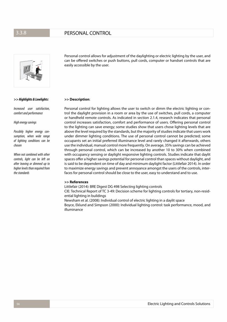
Electric Lighting and Controls Solutions56
3.2.1. PERSONAL CONTROL3.3.8
Personal control allows for adjustment of the daylighting or electric lighting by the user, and can be ofered switches or push buttons, pull cords, computer or handset controls that are easily accessible by the user.
>> Description:
Personal control for lighting allows the user to switch or dimm the electric lighting or con-trol the daylight provision in a room or area by the use of switches, pull cords, a computer or handheld remote controls. As indicated in section 2.1.4, research indicates that personal control increases satisfaction, comfort and performance of users. Ofering personal control to the lighting can save energy; some studies show that users chose lighting levels that are above the level required by the standards, but the majority of studies indicate that users work under dimmer lighting conditions. The use of personal control cannot be predicted; some occupants set an initial preferred illuminance level and rarely changed it afterwards, others use the individual, manual control more frequently. On average, 35% savings can be achieved through personal control, which can be increased by another 10 to 30% when combined with occupancy sensing or daylight responsive lighting controls. Studies indicate that daylit spaces ofer a higher savings potential for personal control than spaces without daylight, and is said to be dependent on time of day and minimum daylight factor (Littlefair 2014). In order to maximize energy savings and prevent annoyance amongst the users of the controls, inter-faces for personal control should be close to the user, easy to understand and to use.
>> References
Littlefair (2014): BRE Digest DG 498 Selecting lighting controlsCIE: Technical Report of TC 3-49: Decision scheme for lighting controls for tertiary, non-resid-ential lighting in buildingsNewsham et al. (2008): Individual control of electric lighting in a daylit spaceBoyce, Eklund and Simpson (2000): Individual lighting control: task performance, mood, and illuminance
>> Highlights & Lowlights:
Increased user satisfaction,
comfort and performance
High energy savings
Possibily higher energy con-
sumption, when wide range
of lighting conditions can be
chosen
When not combined with other
controls, light can be left on
after leaving or dimmed up to
higher levels than required from
the standards
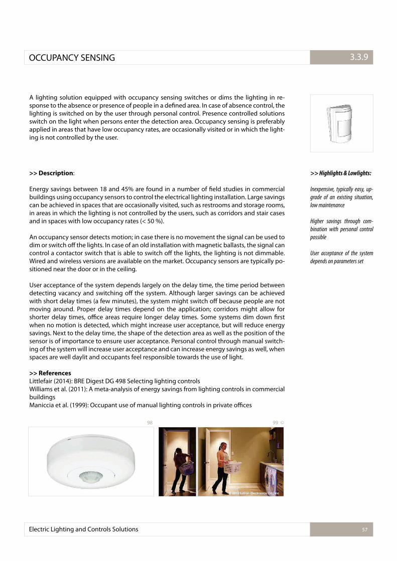
Electric Lighting and Controls Solutions 57
3.2.1.OCCUPANCY SENSING 3.3.9
A lighting solution equipped with occupancy sensing switches or dims the lighting in re-sponse to the absence or presence of people in a deined area. In case of absence control, the lighting is switched on by the user through personal control. Presence controlled solutions switch on the light when persons enter the detection area. Occupancy sensing is preferably applied in areas that have low occupancy rates, are occasionally visited or in which the light-ing is not controlled by the user.
>> Description:
Energy savings between 18 and 45% are found in a number of ield studies in commercial buildings using occupancy sensors to control the electrical lighting installation. Large savings can be achieved in spaces that are occasionally visited, such as restrooms and storage rooms, in areas in which the lighting is not controlled by the users, such as corridors and stair cases and in spaces with low occupancy rates (< 50 %).
An occupancy sensor detects motion; in case there is no movement the signal can be used to dim or switch of the lights. In case of an old installation with magnetic ballasts, the signal can control a contactor switch that is able to switch of the lights, the lighting is not dimmable. Wired and wireless versions are available on the market. Occupancy sensors are typically po-sitioned near the door or in the ceiling.
User acceptance of the system depends largely on the delay time, the time period between detecting vacancy and switching of the system. Although larger savings can be achieved with short delay times (a few minutes), the system might switch of because people are not moving around. Proper delay times depend on the application; corridors might allow for shorter delay times, oice areas require longer delay times. Some systems dim down irst when no motion is detected, which might increase user acceptance, but will reduce energy savings. Next to the delay time, the shape of the detection area as well as the position of the sensor is of importance to ensure user acceptance. Personal control through manual switch-ing of the system will increase user acceptance and can increase energy savings as well, when spaces are well daylit and occupants feel responsible towards the use of light.
>> References
Littlefair (2014): BRE Digest DG 498 Selecting lighting controlsWilliams et al. (2011): A meta-analysis of energy savings from lighting controls in commercial buildingsManiccia et al. (1999): Occupant use of manual lighting controls in private oices
>> Highlights & Lowlights:
Inexpensive, typically easy, up-
grade of an existing situation,
low maintenance
Higher savings through com-
bination with personal control
possible
User acceptance of the system
depends on parameters set
98 99 ©
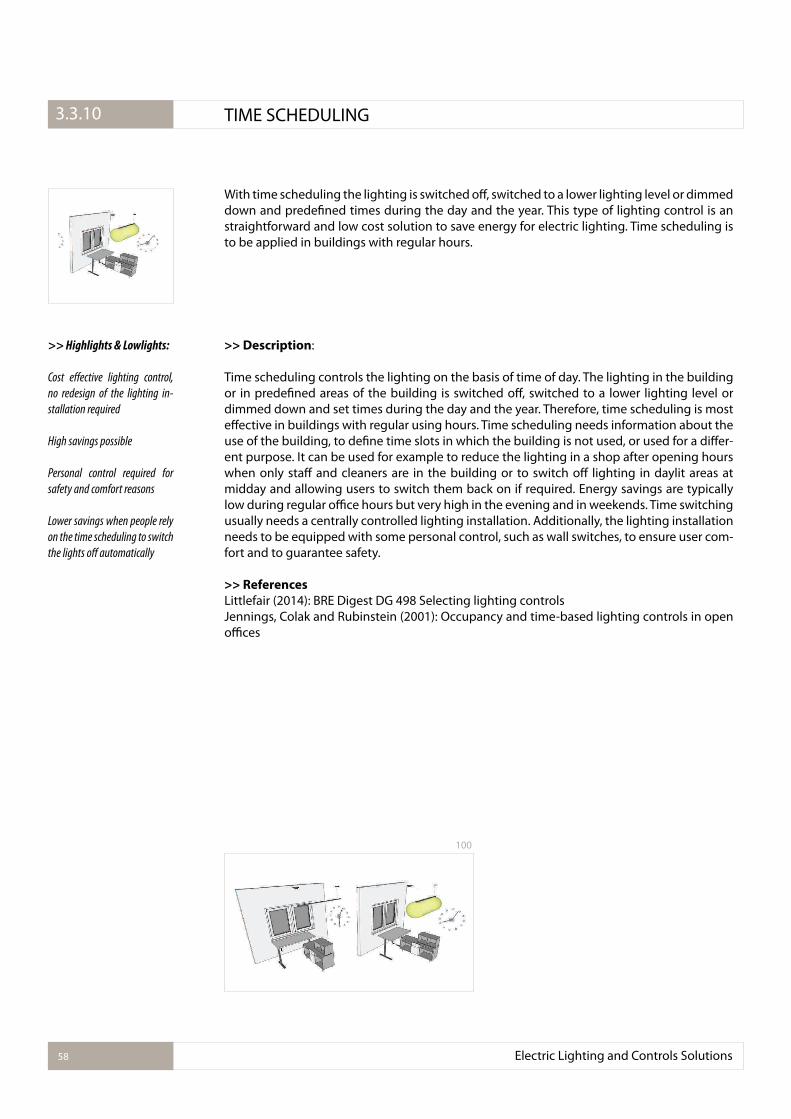
Electric Lighting and Controls Solutions58
3.2.1. TIME SCHEDULING3.3.10
With time scheduling the lighting is switched of, switched to a lower lighting level or dimmed down and predeined times during the day and the year. This type of lighting control is an straightforward and low cost solution to save energy for electric lighting. Time scheduling is to be applied in buildings with regular hours.
>> Description:
Time scheduling controls the lighting on the basis of time of day. The lighting in the building or in predeined areas of the building is switched of, switched to a lower lighting level or dimmed down and set times during the day and the year. Therefore, time scheduling is most efective in buildings with regular using hours. Time scheduling needs information about the use of the building, to deine time slots in which the building is not used, or used for a difer-ent purpose. It can be used for example to reduce the lighting in a shop after opening hours when only staf and cleaners are in the building or to switch of lighting in daylit areas at midday and allowing users to switch them back on if required. Energy savings are typically low during regular oice hours but very high in the evening and in weekends. Time switching usually needs a centrally controlled lighting installation. Additionally, the lighting installation needs to be equipped with some personal control, such as wall switches, to ensure user com-fort and to guarantee safety.
>> References
Littlefair (2014): BRE Digest DG 498 Selecting lighting controlsJennings, Colak and Rubinstein (2001): Occupancy and time-based lighting controls in open oices
>> Highlights & Lowlights:
Cost efective lighting control,
no redesign of the lighting in-
stallation required
High savings possible
Personal control required for
safety and comfort reasons
Lower savings when people rely
on the time scheduling to switch
the lights of automatically
100
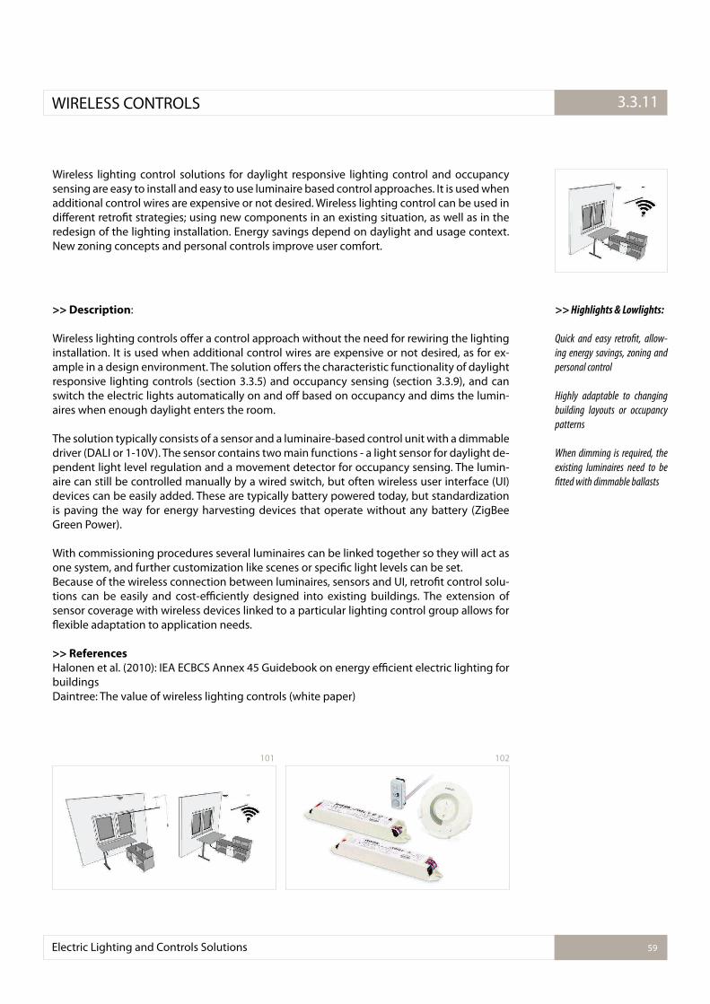
Electric Lighting and Controls Solutions 59
3.2.1.WIRELESS CONTROLS 3.3.11
Wireless lighting control solutions for daylight responsive lighting control and occupancy sensing are easy to install and easy to use luminaire based control approaches. It is used when additional control wires are expensive or not desired. Wireless lighting control can be used in diferent retroit strategies; using new components in an existing situation, as well as in the redesign of the lighting installation. Energy savings depend on daylight and usage context. New zoning concepts and personal controls improve user comfort.
>> Description:
Wireless lighting controls ofer a control approach without the need for rewiring the lighting installation. It is used when additional control wires are expensive or not desired, as for ex-ample in a design environment. The solution ofers the characteristic functionality of daylight responsive lighting controls (section 3.3.5) and occupancy sensing (section 3.3.9), and can switch the electric lights automatically on and of based on occupancy and dims the lumin-aires when enough daylight enters the room.
The solution typically consists of a sensor and a luminaire-based control unit with a dimmable driver (DALI or 1-10V). The sensor contains two main functions - a light sensor for daylight de-pendent light level regulation and a movement detector for occupancy sensing. The lumin-aire can still be controlled manually by a wired switch, but often wireless user interface (UI) devices can be easily added. These are typically battery powered today, but standardization is paving the way for energy harvesting devices that operate without any battery (ZigBee Green Power).
With commissioning procedures several luminaires can be linked together so they will act as one system, and further customization like scenes or speciic light levels can be set.Because of the wireless connection between luminaires, sensors and UI, retroit control solu-tions can be easily and cost-eiciently designed into existing buildings. The extension of sensor coverage with wireless devices linked to a particular lighting control group allows for lexible adaptation to application needs.
>> References
Halonen et al. (2010): IEA ECBCS Annex 45 Guidebook on energy eicient electric lighting for buildingsDaintree: The value of wireless lighting controls (white paper)
>> Highlights & Lowlights:
Quick and easy retroit, allow-
ing energy savings, zoning and
personal control
Highly adaptable to changing
building layouts or occupancy
patterns
When dimming is required, the
existing luminaires need to be
itted with dimmable ballasts
101 102
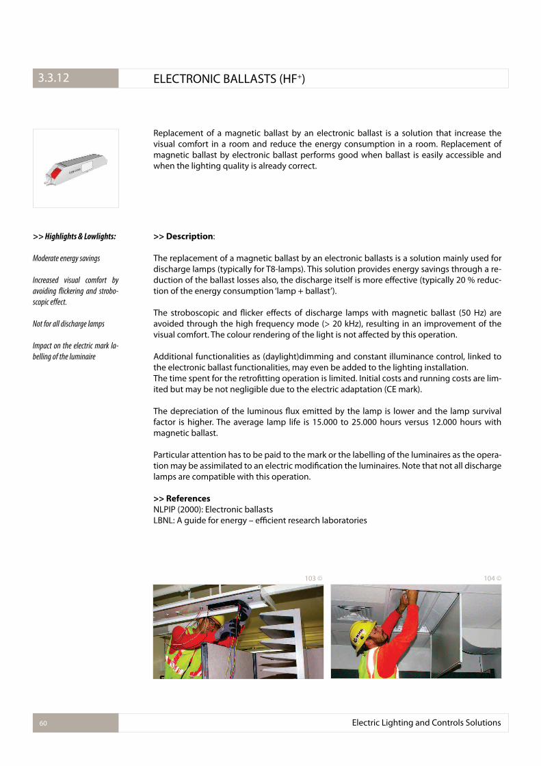
Electric Lighting and Controls Solutions60
3.2.1. ELECTRONIC BALLASTS (HF+)3.3.12
Replacement of a magnetic ballast by an electronic ballast is a solution that increase the visual comfort in a room and reduce the energy consumption in a room. Replacement of magnetic ballast by electronic ballast performs good when ballast is easily accessible and when the lighting quality is already correct.
>> Description:
The replacement of a magnetic ballast by an electronic ballasts is a solution mainly used for discharge lamps (typically for T8-lamps). This solution provides energy savings through a re-duction of the ballast losses also, the discharge itself is more efective (typically 20 % reduc-tion of the energy consumption ‘lamp + ballast’).
The stroboscopic and licker efects of discharge lamps with magnetic ballast (50 Hz) are avoided through the high frequency mode (> 20 kHz), resulting in an improvement of the visual comfort. The colour rendering of the light is not afected by this operation.
Additional functionalities as (daylight)dimming and constant illuminance control, linked to the electronic ballast functionalities, may even be added to the lighting installation.The time spent for the retroitting operation is limited. Initial costs and running costs are lim-ited but may be not negligible due to the electric adaptation (CE mark).
The depreciation of the luminous lux emitted by the lamp is lower and the lamp survival factor is higher. The average lamp life is 15.000 to 25.000 hours versus 12.000 hours with magnetic ballast.
Particular attention has to be paid to the mark or the labelling of the luminaires as the opera-tion may be assimilated to an electric modiication the luminaires. Note that not all discharge lamps are compatible with this operation.
>> References
NLPIP (2000): Electronic ballastsLBNL: A guide for energy – eicient research laboratories
>> Highlights & Lowlights:
Moderate energy savings
Increased visual comfort by
avoiding lickering and strobo-
scopic efect.
Not for all discharge lamps
Impact on the electric mark la-
belling of the luminaire
103 © 104 ©
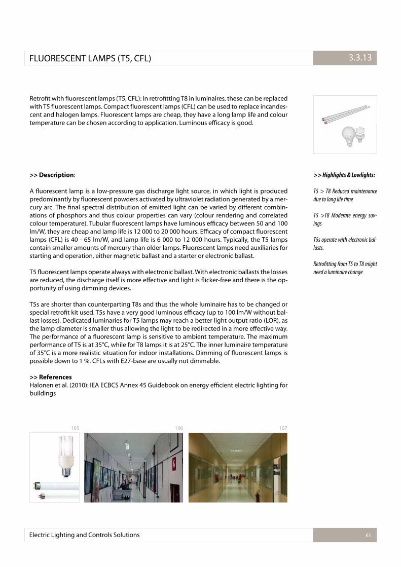
Electric Lighting and Controls Solutions 61
3.2.1.FLUORESCENT LAMPS (T5, CFL) 3.3.13
Retroit with luorescent lamps (T5, CFL): In retroitting T8 in luminaires, these can be replaced with T5 luorescent lamps. Compact luorescent lamps (CFL) can be used to replace incandes-cent and halogen lamps. Fluorescent lamps are cheap, they have a long lamp life and colour temperature can be chosen according to application. Luminous eicacy is good.
>> Description:
A luorescent lamp is a low-pressure gas discharge light source, in which light is produced predominantly by luorescent powders activated by ultraviolet radiation generated by a mer-cury arc. The inal spectral distribution of emitted light can be varied by diferent combin-ations of phosphors and thus colour properties can vary (colour rendering and correlated colour temperature). Tubular luorescent lamps have luminous eicacy between 50 and 100 lm/W, they are cheap and lamp life is 12 000 to 20 000 hours. Eicacy of compact luorescent lamps (CFL) is 40 - 65 lm/W, and lamp life is 6 000 to 12 000 hours. Typically, the T5 lamps contain smaller amounts of mercury than older lamps. Fluorescent lamps need auxiliaries for starting and operation, either magnetic ballast and a starter or electronic ballast.
T5 luorescent lamps operate always with electronic ballast. With electronic ballasts the losses are reduced, the discharge itself is more efective and light is licker-free and there is the op-portunity of using dimming devices.
T5s are shorter than counterparting T8s and thus the whole luminaire has to be changed or special retroit kit used. T5s have a very good luminous eicacy (up to 100 lm/W without bal-last losses). Dedicated luminaries for T5 lamps may reach a better light output ratio (LOR), as the lamp diameter is smaller thus allowing the light to be redirected in a more efective way. The performance of a luorescent lamp is sensitive to ambient temperature. The maximum performance of T5 is at 35°C, while for T8 lamps it is at 25°C. The inner luminaire temperature of 35°C is a more realistic situation for indoor installations. Dimming of luorescent lamps is possible down to 1 %. CFLs with E27-base are usually not dimmable.
>> References
Halonen et al. (2010): IEA ECBCS Annex 45 Guidebook on energy eicient electric lighting for buildings
>> Highlights & Lowlights:
T5 > T8 Reduced maintenance
due to long life time
T5 >T8 Moderate energy sav-
ings
T5s operate with electronic bal-
lasts.
Retroitting from T5 to T8 might
need a luminaire change
106 107105
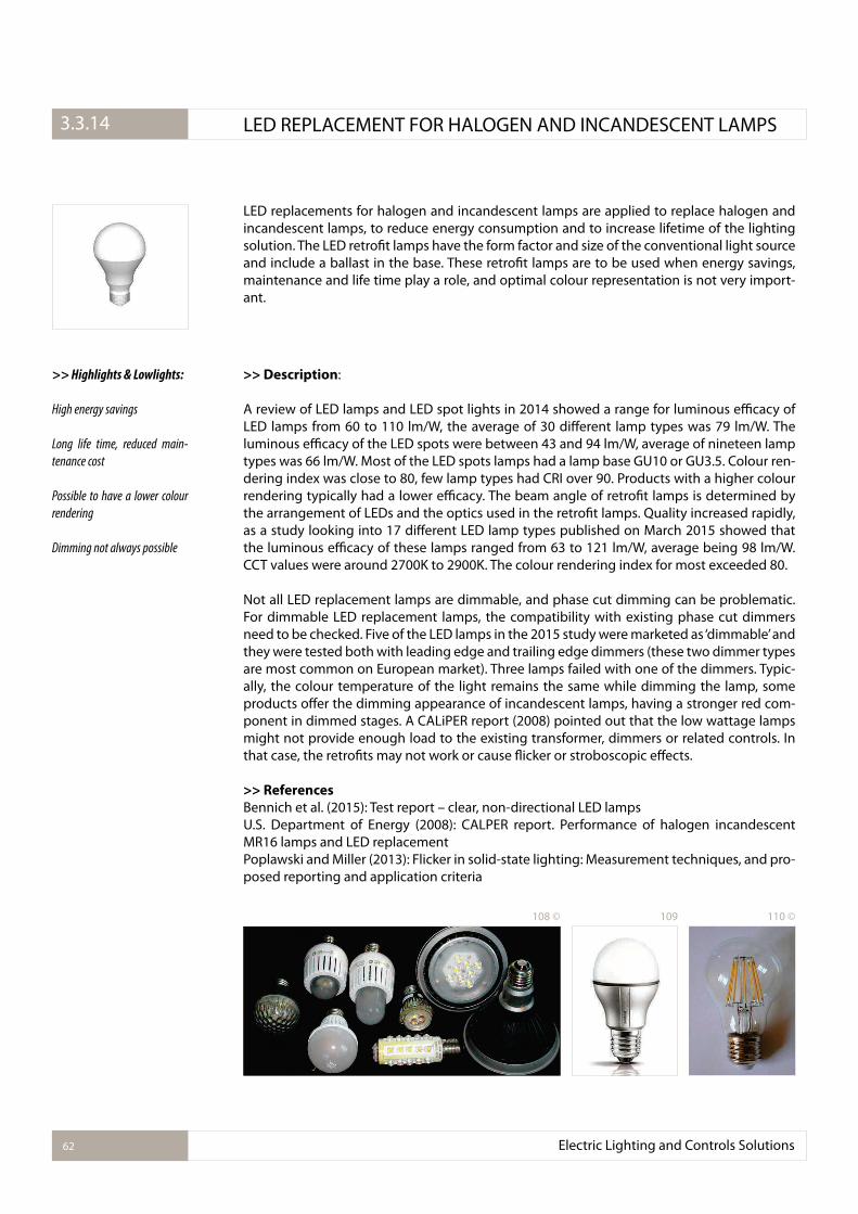
Electric Lighting and Controls Solutions62
3.2.1. LED REPLACEMENT FOR HALOGEN AND INCANDESCENT LAMPS3.3.14
LED replacements for halogen and incandescent lamps are applied to replace halogen and incandescent lamps, to reduce energy consumption and to increase lifetime of the lighting solution. The LED retroit lamps have the form factor and size of the conventional light source and include a ballast in the base. These retroit lamps are to be used when energy savings, maintenance and life time play a role, and optimal colour representation is not very import-ant.
>> Description:
A review of LED lamps and LED spot lights in 2014 showed a range for luminous eicacy of LED lamps from 60 to 110 lm/W, the average of 30 diferent lamp types was 79 lm/W. The luminous eicacy of the LED spots were between 43 and 94 lm/W, average of nineteen lamp types was 66 lm/W. Most of the LED spots lamps had a lamp base GU10 or GU3.5. Colour ren-dering index was close to 80, few lamp types had CRI over 90. Products with a higher colour rendering typically had a lower eicacy. The beam angle of retroit lamps is determined by the arrangement of LEDs and the optics used in the retroit lamps. Quality increased rapidly, as a study looking into 17 diferent LED lamp types published on March 2015 showed that the luminous eicacy of these lamps ranged from 63 to 121 lm/W, average being 98 lm/W. CCT values were around 2700K to 2900K. The colour rendering index for most exceeded 80.
Not all LED replacement lamps are dimmable, and phase cut dimming can be problematic. For dimmable LED replacement lamps, the compatibility with existing phase cut dimmers need to be checked. Five of the LED lamps in the 2015 study were marketed as ‘dimmable’ and they were tested both with leading edge and trailing edge dimmers (these two dimmer types are most common on European market). Three lamps failed with one of the dimmers. Typic-ally, the colour temperature of the light remains the same while dimming the lamp, some products ofer the dimming appearance of incandescent lamps, having a stronger red com-ponent in dimmed stages. A CALiPER report (2008) pointed out that the low wattage lamps might not provide enough load to the existing transformer, dimmers or related controls. In that case, the retroits may not work or cause licker or stroboscopic efects.
>> References
Bennich et al. (2015): Test report – clear, non-directional LED lamps U.S. Department of Energy (2008): CALPER report. Performance of halogen incandescent MR16 lamps and LED replacementPoplawski and Miller (2013): Flicker in solid-state lighting: Measurement techniques, and pro-posed reporting and application criteria
>> Highlights & Lowlights:
High energy savings
Long life time, reduced main-
tenance cost
Possible to have a lower colour
rendering
Dimming not always possible
110 ©108 © 109
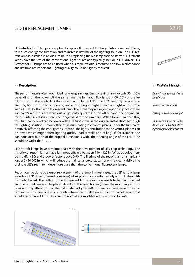
Electric Lighting and Controls Solutions 63
3.2.1.LED T8 REPLACEMENT LAMPS 3.3.15
LED retroits for T8 lamps are applied to replace luorescent lighting solutions with a G3 base, to reduce energy consumption and to increase lifetime of the lighting solution. The LED ret-roit lamp is installed in an old luminaire by replacing the old lamp and the starter. LED retroit lamps have the size of the conventional light source and typically include a LED driver. LED Retroit for T8 lamps are to be used when a simple retroit is required and low maintenance and life time are important. Lighting quality could be slightly reduced.
>> Description:
The performance is often optimized for energy savings. Energy savings are typically 50…60% depending on the power. At the same time the luminous lux is about 60...70% of the lu-minous lux of the equivalent luorescent lamp. In the LED tube LEDs are only on one side emitting light to a speciic opening angle, resulting in higher luminaire light output ratio with a LED tube than with luorescent lamp. Therefore they are a good option in places where luminaire’s relectors are worn out or get dirty quickly. On the other hand, the original lu-minous intensity distribution is no longer valid for the luminaire. With a lower luminous lux, the illuminance level can be lower with LED tubes than in the original installation. Although the lighting solution is more eicient in illuminating horizontal planes under the luminaire, positively afecting the energy consumption, the light contribution to the vertical planes can be lower, which might afect lighting quality (darker walls and ceiling). If, for instance, the luminous distribution of the original luminaire is wide, the opening angle of the LED tube should be wider than 120°.
LED retroit lamps have developed fast with the development of LED chip technology. The majority of retroit lamps has a luminous eicacy between 110 - 120 lm/W, good colour ren-dering (Ra > 80) and a power factor above 0.90. The lifetime of the retroit lamps is typically longer (> 50 000 h), which will reduce the maintenance costs. Lamps with a clearly visible line of single LEDs seem to induce more glare than the conventional luorescent lamps.
Retroit can be done by a quick replacement of the lamp. In most cases, the LED retroit lamp includes a LED driver (internal converter). Most products are suitable only to luminaires with magnetic ballast. The ballast of the luorescent lighting solution needs to be disconnected and the retroit lamp can be placed directly in the lamp holder (follow the mounting instruc-tions and pay attention that the old starter is bypassed). If there is a compensation capa-citor in the luminaire, one should conirm from the installation instructions, whether or not it should be removed. LED tubes are not normally compatible with electronic ballasts.
>> Highlights & Lowlights:
Reduced maintenance due to
long life time
Moderate energy savings
Possibly weak on lumen output
Smaller beam angle can lead to
darker walls and ceiling, afect-
ing room appearance negatively
111 © 112
Electric Lighting and Controls Solutions64
>> References
U.S. Department of Energy (2009): CALiPER Benchmark Report - Performance of T12 and T8 luorescent lamps and trofers and LED linear replacement lamps Ryckaert et al. (2012): Performance of LED linear replacement lampsRyckaert et al. (2012): Linear LED tubes versus luorescent lamps: An evaluation Richman, Kinzey and Miller (2011): U.S. DOE Solid-State Lighting Technology Demonstration GATEWAY Program. Laboratory Evaluation of Light-Emitting Diode (LED) T8 Replacement Lamp Products
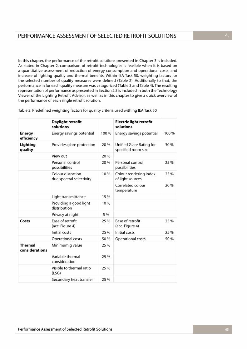
Performance Assessment of Selected Retroit Solutions 65
3.2.1.PERFORMANCE ASSESSMENT OF SELECTED RETROFIT SOLUTIONS 4.
In this chapter, the performance of the retroit solutions presented in Chapter 3 is included. As stated in Chapter 2, comparison of retroit technologies is feasible when it is based on a quantitative assessment of reduction of energy consumption and operational costs, and increase of lighting qualtiy and thermal beneits. Within IEA Task 50, weighting factors for the selected number of quality measures were deined (Table 2). Additionally to that, the performance in for each quality measure was catagorized (Table 3 and Table 4). The resulting representation of performance as presented in Section 2.3 is included in both the Technology Viewer of the Lighting Retroit Advisor, as well as in this chapter to give a quick overview of the performance of each single retroit solution.
Table 2: Predeined weighting factors for quality criteria used withing IEA Task 50
Daylight retro�t
solutions
Electric light retro�t
solutions
Energy
eiciency
Energy savings potential 100 % Energy savings potential 100 %
Lighting
quality
Provides glare protection 20 % Uniied Glare Rating for speciied room size
30 %
View out 20 %
Personal control possibilities
20 % Personal control possibilities
25 %
Colour distortion due spectral selectivity
10 % Colour rendering index of light sources
25 %
Correlated colour temperature
20 %
Light transmittance 15 %
Providing a good light distribution
10 %
Privacy at night 5 %
Costs Ease of retroit (acc. Figure 4)
25 % Ease of retroit (acc. Figure 4)
25 %
Initial costs 25 % Initial costs 25 %
Operational costs 50 % Operational costs 50 %
Thermal
considerations
Minimum g value 25 %
Variable thermal consideration
25 %
Visible to thermal ratio (LSG)
25 %
Secondary heat transfer 25 %
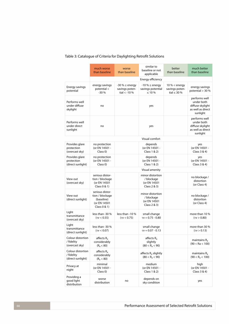
Performance Assessment of Selected Retroit Solutions66
Table 3: Catalogue of Criteria for Daylighting Retroit Solutions
much worse than baseline
worsethan baseline
similar to baseline or not
applicable
better than baseline
much better than baseline
Energy eiciency
Energy savings potential
energy savings potential <
-30 %
-30 % ≤ energy savings poten-
tial < -10 %
-10 % ≤ energy savings potential
≤ 10 %
10 % < energy savings poten-
tial ≤ 30 %
energy savings potential > 30 %
Performs well under difuse skylight
no yes
performs well under both
difuse skylight as well as direct
sunlight
Performs well under direct sunlight
no yes
performs well under both
difuse skylight as well as direct
sunlight
Visual comfort
Provides glare protection(overcast sky)
no protection (or EN 14501 -
Class 0)
depends(or EN 14501 -
Class 1 & 2)
yes(or EN 14501 -
Class 3 & 4)
Provides glare protection (direct sunlight)
no protection(or EN 14501 -
Class 0)
depends(or EN 14501 -
Class 1 & 2)
yes(or EN 14501 -
Class 3 & 4)
Visual amenity
View out (overcast sky)
serious distor-tion / blockage
(or EN 14501 Class 0 & 1)
minor distortion / blockage
(or EN 14501 Class 2 & 3)
no blockage / distortion (or Class 4)
View out (direct sunlight)
serious distor-tion / blockage
(baseline) (or EN 14501 Class 0 & 1)
minor distortion / blockage
(or EN 14501 Class 2 & 3)
no blockage / distortion (or Class 4)
Light transmittance (overcast sky)
less than -30 % ( v < 0.55)
less than -10 % ( v < 0.75)
small change v = 0.75 - 0.80
more than 10 % ( v > 0.80)
Light transmittance(direct sunlight)
less than -30 % ( v < 0.07)
small change v = 0.07 - 0.13
more than 30 % ( v > 0.13)
Colour distortion / idelity (overcast sky)
afects Ra considerably
(Ra < 80)
afects Ra
slightly(80 < Ra < 90)
maintains Ra
(90 < Ra < 100)
Colour distortion / idelity (direct sunlight)
afects Ra considerably
(Ra < 80)
afects Ra slightly(80 < Ra < 90)
maintains Ra (90 < Ra < 100)
Privacy atnight
minimal (or EN 14501 -
Class 0)
medium (or EN 14501 -
Class 1 & 2)
high (or EN 14501 -
Class 3 & 4)
Providing a good light distribution
worse distribution
nodepends on
sky conditionyes
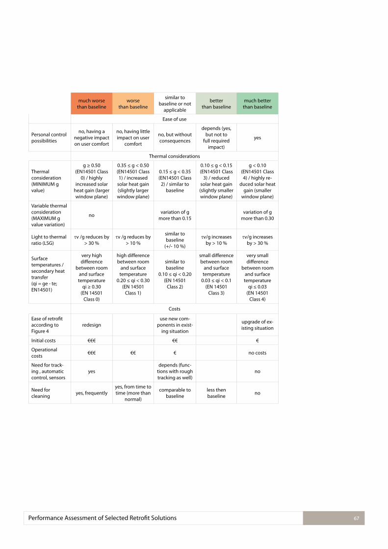
Performance Assessment of Selected Retroit Solutions 67
much worse than baseline
worsethan baseline
similar to baseline or not
applicable
better than baseline
much better than baseline
Ease of use
Personal control possibilities
no, having a negative impact on user comfort
no, having little impact on user
comfort
no, but without consequences
depends (yes, but not to
full required impact)
yes
Thermal considerations
Thermal consideration (MINIMUM g value)
g ≥ 0.50 (EN14501 Class
0) / highly increased solar
heat gain (larger window plane)
0.35 ≤ g < 0.50 (EN14501 Class 1) / increased
solar heat gain (slightly larger window plane)
0.15 ≤ g < 0.35 (EN14501 Class
2) / similar to baseline
0.10 ≤ g < 0.15 (EN14501 Class
3) / reduced solar heat gain (slightly smaller window plane)
g < 0.10 (EN14501 Class 4) / highly re-
duced solar heat gain (smaller
window plane)
Variable thermal consideration (MAXIMUM g value variation)
novariation of g
more than 0.15variation of g
more than 0.30
Light to thermal ratio (LSG)
v /g reduces by > 30 %
v /g reduces by > 10 %
similar to baseline
(+/- 10 %)
v/g increases by > 10 %
v/g increases by > 30 %
Surface temperatures / secondary heat transfer (qi = ge - te; EN14501)
very high diference
between room and surface temperature
qi ≥ 0.30 (EN 14501
Class 0)
high diference between room
and surface temperature
0.20 ≤ qi < 0.30 (EN 14501
Class 1)
similar to baseline
0.10 ≤ qi < 0.20 (EN 14501
Class 2)
small diference between room
and surface temperature
0.03 ≤ qi < 0.1 (EN 14501
Class 3)
very small diference
between room and surface temperature
qi ≤ 0.03 (EN 14501
Class 4)
Costs
Ease of retroit according to Figure 4
redesignuse new com-
ponents in exist-ing situation
upgrade of ex-isting situation
Initial costs €€€ €€ €
Operational costs
€€€ €€ € no costs
Need for track-ing , automatic control, sensors
yesdepends (func-
tions with rough tracking as well)
no
Need for cleaning
yes, frequentlyyes, from time to time (more than
normal)
comparable to baseline
less then baseline
no
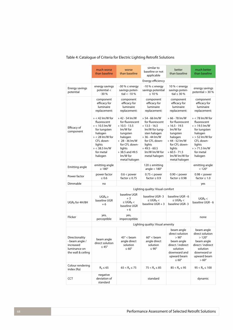
Performance Assessment of Selected Retroit Solutions68
Table 4: Catalogue of Criteria for Electric Lighting Retroit Solutions
much worse than baseline
worsethan baseline
similar to baseline or not
applicable
better than baseline
much better than baseline
Energy eiciency
Energy savings potential
energy savings potential <
-30 %
-30 % ≤ energy savings poten-
tial < -10 %
-10 % ≤ energy savings potential
≤ 10 %
10 % < energy savings poten-
tial ≤ 30 %
energy savings potential > 30 %
Eicacy of component
component eicacy for luminaire
replacement:
» < 42 lm/W for luorescent
» < 10.5 lm/W for tungsten halogen
» < 28 lm/W for CFL down-lights
» < 38.5 lm/W for metal halogen
component eicacy for luminaire
replacement:
» 42 - 54 lm/W for luorescent
» 10.5 - 13.5 lm/W for tungsten halogen
» 28 - 36 lm/W for CFL down-lights
» 38.5 and 49.5 lm/W for metal halogen
component eicacy for luminaire
replacement:
» 54 - 66 lm/W for luorescent
» 13.5 - 16.5 lm/W for tung-sten halogen
» 36 - 44 lm/W for CFL down-lights
» 49.5 - 60.5 lm/W lm/W for metal halogen
component eicacy for luminaire
replacement:
» 66 - 78 lm/W for luorescent
» 16.5 - 19.5 lm/W for tungsten halogen
» 44 - 52 lm/W for CFL down-lights
» 60.5 - 71.5 lm/W lm/W for metal halogen
component eicacy for luminaire
replacement:
» < 78 lm/W for luorescent
» > 19.5 lm/W for tungsten halogen
» > 52 lm/W for CFL down-lights
» > 71.5 lm/W for metal halogen
Emitting angleemitting angle
≥ 180°120 ≤ emitting
angle < 180°emitting angle
< 120°
Power factorpower factor
≤ 0.60.6 < power factor ≤ 0.75
0.75 < power factor ≤ 0.9
0.90 < power factor ≤ 0.98
0.98 < power factor ≤ 1.0
Dimmable no yes
Lighting quality: Visual comfort
UGRR for 4H/8H
UGRR ≥baseline UGR
+ 6
baseline UGR + 3
≤ UGRR < baseline UGR
+ 6
baseline UGR- 3≤ UGRR <
baseline UGR + 3
baseline UGR - 6≤ UGRR <
baseline UGR- 3
UGRR < baseline UGR - 6
Flickeryes,
perceptibleyes,
imperceptiblenone
Lighting quality: Visual amenity
Directionality - beam angle / increased luminance on the wall & ceiling
beam angle direct solution
≤ 45°
45° < beam angle direct
solution ≤ 60°
60° < beam angle direct
solution ≤ 90°
beam angle direct solution
> 90°beam angle
direct / indirect solution
downward and upward beam
≤ 60°
beam angle direct solution
> 120°beam angle
direct / indirect solution
downward or upward beam
> 60°
Colour rendering index (Ra) Ra ≤ 65 65 < Ra ≤ 75 75 < Ra ≤ 85 85 < Ra ≤ 95 95 < Ra ≤ 100
CCTnegative
deviation of standard
standard dynamic
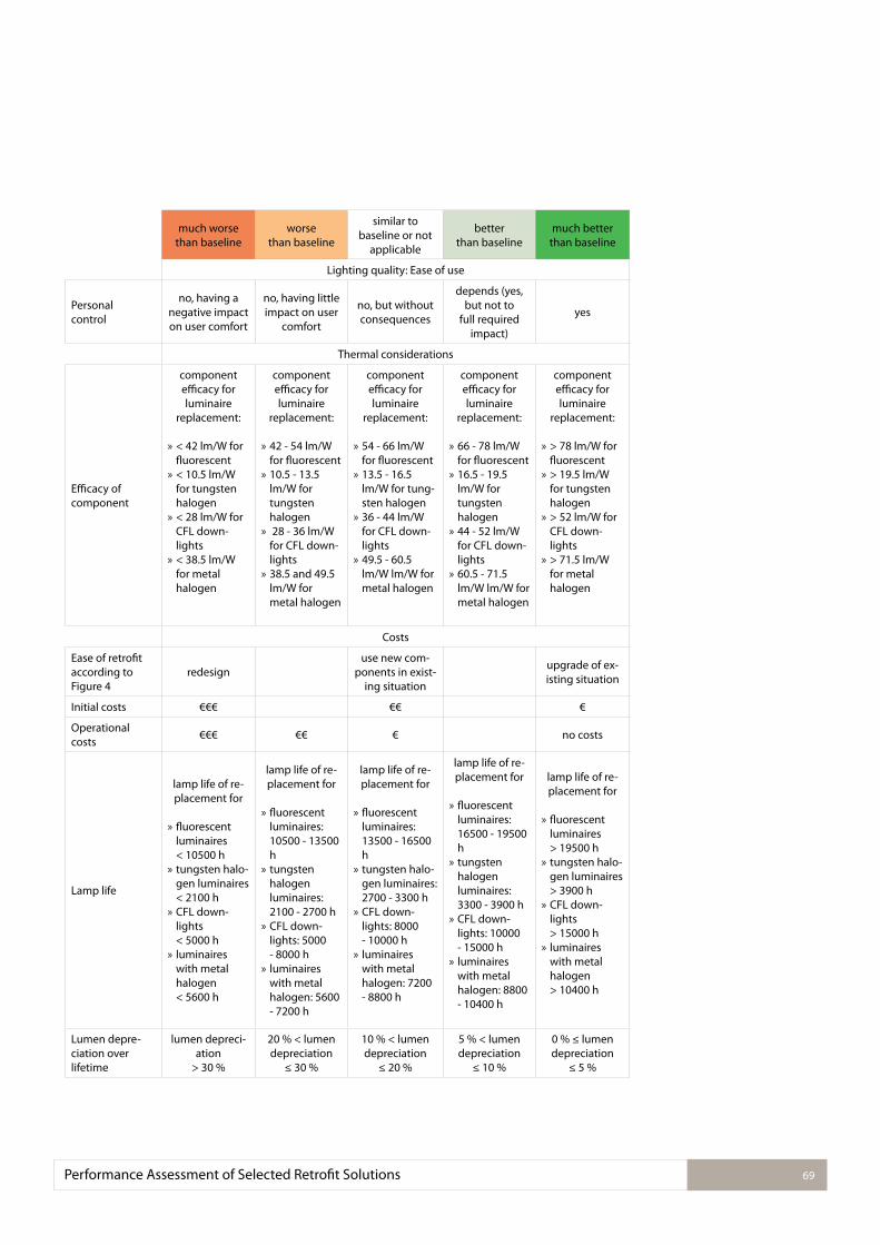
Performance Assessment of Selected Retroit Solutions 69
much worse than baseline
worsethan baseline
similar to baseline or not
applicable
better than baseline
much better than baseline
Lighting quality: Ease of use
Personal control
no, having a negative impact on user comfort
no, having little impact on user
comfort
no, but without consequences
depends (yes, but not to
full required impact)
yes
Thermal considerations
Eicacy of component
component eicacy for luminaire
replacement:
» < 42 lm/W for luorescent
» < 10.5 lm/W for tungsten halogen
» < 28 lm/W for CFL down-lights
» < 38.5 lm/W for metal halogen
component eicacy for luminaire
replacement:
» 42 - 54 lm/W for luorescent
» 10.5 - 13.5 lm/W for tungsten halogen
» 28 - 36 lm/W for CFL down-lights
» 38.5 and 49.5 lm/W for metal halogen
component eicacy for luminaire
replacement:
» 54 - 66 lm/W for luorescent
» 13.5 - 16.5 lm/W for tung-sten halogen
» 36 - 44 lm/W for CFL down-lights
» 49.5 - 60.5 lm/W lm/W for metal halogen
component eicacy for luminaire
replacement:
» 66 - 78 lm/W for luorescent
» 16.5 - 19.5 lm/W for tungsten halogen
» 44 - 52 lm/W for CFL down-lights
» 60.5 - 71.5 lm/W lm/W for metal halogen
component eicacy for luminaire
replacement:
» > 78 lm/W for luorescent
» > 19.5 lm/W for tungsten halogen
» > 52 lm/W for CFL down-lights
» > 71.5 lm/W for metal halogen
Costs
Ease of retroit according to Figure 4
redesignuse new com-
ponents in exist-ing situation
upgrade of ex-isting situation
Initial costs €€€ €€ €
Operational costs
€€€ €€ € no costs
Lamp life
lamp life of re-placement for
» luorescent luminaires < 10500 h
» tungsten halo-gen luminaires < 2100 h
» CFL down-lights < 5000 h
» luminaires with metal halogen < 5600 h
lamp life of re-placement for
» luorescent luminaires: 10500 - 13500 h
» tungsten halogen luminaires: 2100 - 2700 h
» CFL down-lights: 5000 - 8000 h
» luminaires with metal halogen: 5600 - 7200 h
lamp life of re-placement for
» luorescent luminaires: 13500 - 16500 h
» tungsten halo-gen luminaires: 2700 - 3300 h
» CFL down-lights: 8000 - 10000 h
» luminaires with metal halogen: 7200 - 8800 h
lamp life of re-placement for
» luorescent luminaires: 16500 - 19500 h
» tungsten halogen luminaires: 3300 - 3900 h
» CFL down-lights: 10000 - 15000 h
» luminaires with metal halogen: 8800 - 10400 h
lamp life of re-placement for
» luorescent luminaires > 19500 h
» tungsten halo-gen luminaires > 3900 h
» CFL down-lights > 15000 h
» luminaires with metal halogen > 10400 h
Lumen depre-ciation over lifetime
lumen depreci-ation
> 30 %
20 % < lumen depreciation
≤ 30 %
10 % < lumen depreciation
≤ 20 %
5 % < lumen depreciation
≤ 10 %
0 % ≤ lumen depreciation
≤ 5 %
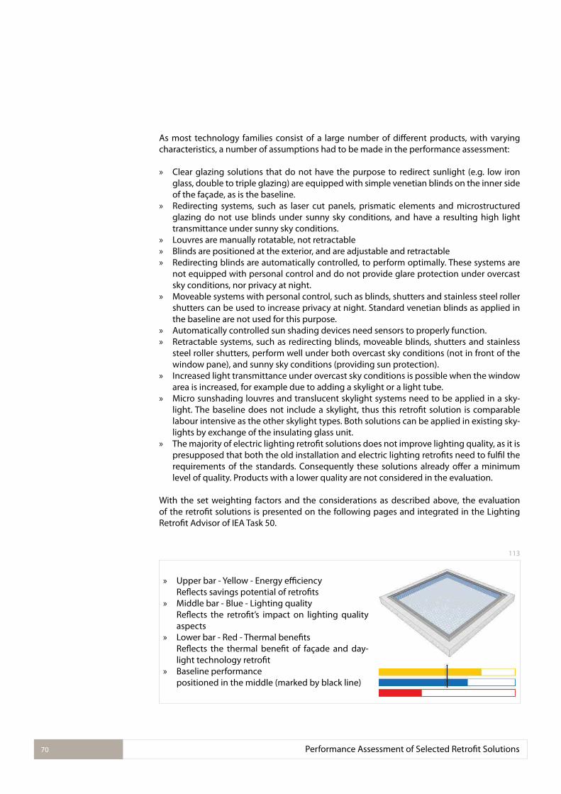
Performance Assessment of Selected Retroit Solutions70
As most technology families consist of a large number of diferent products, with varying characteristics, a number of assumptions had to be made in the performance assessment:
» Clear glazing solutions that do not have the purpose to redirect sunlight (e.g. low iron glass, double to triple glazing) are equipped with simple venetian blinds on the inner side of the façade, as is the baseline.
» Redirecting systems, such as laser cut panels, prismatic elements and microstructured glazing do not use blinds under sunny sky conditions, and have a resulting high light transmittance under sunny sky conditions.
» Louvres are manually rotatable, not retractable » Blinds are positioned at the exterior, and are adjustable and retractable » Redirecting blinds are automatically controlled, to perform optimally. These systems are
not equipped with personal control and do not provide glare protection under overcast sky conditions, nor privacy at night.
» Moveable systems with personal control, such as blinds, shutters and stainless steel roller shutters can be used to increase privacy at night. Standard venetian blinds as applied in the baseline are not used for this purpose.
» Automatically controlled sun shading devices need sensors to properly function. » Retractable systems, such as redirecting blinds, moveable blinds, shutters and stainless
steel roller shutters, perform well under both overcast sky conditions (not in front of the window pane), and sunny sky conditions (providing sun protection).
» Increased light transmittance under overcast sky conditions is possible when the window area is increased, for example due to adding a skylight or a light tube.
» Micro sunshading louvres and translucent skylight systems need to be applied in a sky-light. The baseline does not include a skylight, thus this retroit solution is comparable labour intensive as the other skylight types. Both solutions can be applied in existing sky-lights by exchange of the insulating glass unit.
» The majority of electric lighting retroit solutions does not improve lighting quality, as it is presupposed that both the old installation and electric lighting retroits need to fulil the requirements of the standards. Consequently these solutions already ofer a minimum level of quality. Products with a lower quality are not considered in the evaluation.
With the set weighting factors and the considerations as described above, the evaluation of the retroit solutions is presented on the following pages and integrated in the Lighting Retroit Advisor of IEA Task 50.
113
» Upper bar - Yellow - Energy eiciencyRelects savings potential of retroits
» Middle bar - Blue - Lighting qualityRelects the retroit’s impact on lighting quality aspects
» Lower bar - Red - Thermal beneitsRelects the thermal beneit of façade and day-light technology retroit
» Baseline performance positioned in the middle (marked by black line)
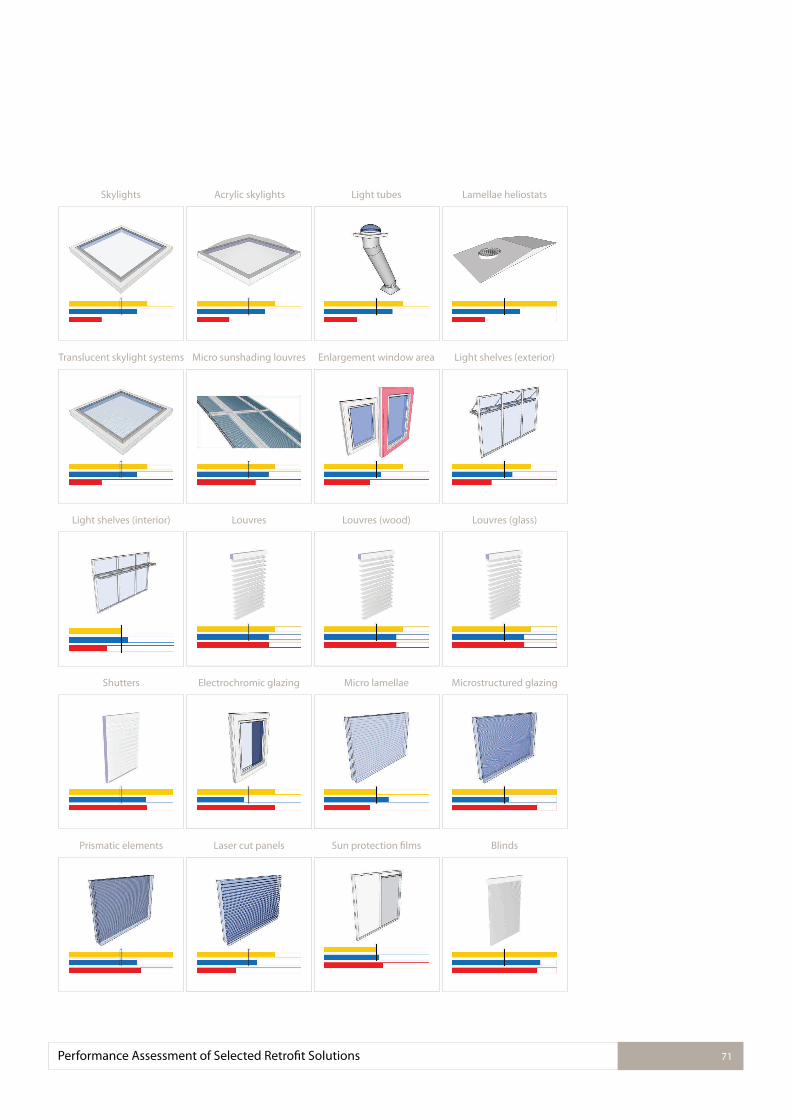
Prismatic elements Laser cut panels Sun protection ilms Blinds
Shutters Electrochromic glazing Micro lamellae Microstructured glazing
Light shelves (interior) Louvres Louvres (wood) Louvres (glass)
Translucent skylight systems Micro sunshading louvres Enlargement window area Light shelves (exterior)
Skylights Acrylic skylights Light tubes Lamellae heliostats
Performance Assessment of Selected Retroit Solutions 71
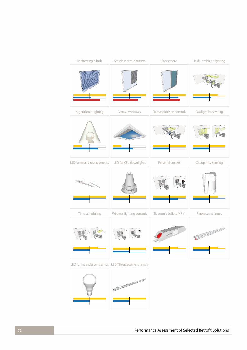
LED luminaire replacements LED for CFL downlights Personal control Occupancy sensing
LED for incandescent lamps LED T8 replacement lamps
Time scheduling Wireless lighting controls Electronic ballast (HF+) Fluorescent lamps
Algorithmic lighting Virtual windows Demand driven controls Daylight harvesting
Redirecting blinds Stainless steel shutters Sunscreens Task - ambient lighting
Performance Assessment of Selected Retroit Solutions 72
Conclusions and Outlook 73
3.2.1.CONCLUSIONS AND OUTLOOK 5.
The work presented in this source book looked into the assessment of a selection of existing and a number of new technical solutions in the ield of façade and daylighting technology, electric lighting and lighting controls.
The appropriateness of a lighting retroit solution largely depends on the reason to retroit, which can be to increase lighting quality, to save energy for electric lighting, to reduce costs or to afect thermal loads. Therefore, lighting retroit solutions need to be evaluated on each of these quality aspects, which is possible with the proposed Catalogue of Criteria. Chapter 3 ofers background information on a large bandwidth of possible retroit solutions, which are assessed in Chapter 4.
The review showed that non-economic beneits, or indirect economic beneits, such as the increase of lighting quality, can be achieved with daylighting retroit solutions that enhance daylight provision in a room, and with electric lighting and control solutions that might re-quire a redesign of the lighting installation. The remaining electric lighting retroit solutions looked into did not improve lighting quality, as it was presupposed that both the old installa-tion and electric lighting retroits need to fulil the lighting quality requirements of the stand-ards.
Whereas replacing a lamp or adding interior blinds are seen as simple retroits, which are widely accepted, this review showed that additionally to that » a task - ambient lighting concept, » occupancy sensing, » personal control in daylit spaces, » daylight responsive lighting control through switching, » time scheduling, » wireless controls (occupancy and daylight responsive), and » replacing an magnetic ballast with an electronic ballast
can be economical solutions that reduce energy consumption for electric lighting.
Daylighting retroit solutions generally have higher investment costs. The full energy savings potential of a retroit that ofers a higher daylight provision can be harvested only when a day-light responsive lighting control solution is installed. The savings potential can be achieved to some extend when personal control over the electric lighting is ofered to the user. Climate or the predominant weather condition should be respected in the choice of a daylighting retroit solutions. Systems that redirect or relect sunlight, avoid overheating, and allow sky light provision in the building are preferred in sunny conditions. In temperate climates, lex-ible systems that ofer one of these two functionalities, but can be retracted under conditions without direct sunlight should be used.
The review was concluded in 2015. It is expected that the development of LEDs will lead to a further reduction of price and increase of eicacy of both retroit lamps and luminaires. These solutions will remain good retroit solutions with an even shorter payback period. It is not likely that the payback period for lighting control solutions and daylighting solutions will become signiicantly shorter in the near future. Lighting control systems are expected to re-duce in cost, but the absolute energy saving for electric lighting will diminish, due to the use of more eicient components. Therfore, the efectiveness of controls to save energy is smaller. It has to be noted, that the use of non renewable resources will still be reduced. The costs for daylighting retroit solutions might only slightly reduce in the near future. The performance of these retroits will stay the same. Therefore, conclusions and guidelines as can be found in this source book, or the source book of IEA Task 21 (Ruck et al. 2000), will remain applicable.
Conclusions and Outlook74
Generally, lighting control solutions and daylighting solutions ofer a higher potential to in-crease user comfort and lighting quality. With the current public interest in light for health and well-being, which is typically addressed with lighting conditions that vary in luminance distribution, light level and / or colour temperature over time, these solutions gain in value at present. Daylight is preferably integrated as it is a very efective light source to cause non-visual responses, due to its availability in large amounts during the day and the strong blue component in its spectrum. Additionally to that, daylight utilization can increase the energy eiciency of lighting installations for health and well-being. Lighting controls should be ap-plied to harvest these saving potentials and to control the electric lighting to realize the re-quired varying lighting conditions.
Summarizing, the development as well as the application of lighting retroit solutions follows a two-way approach. The majority of electric lighting retroit solutions will further focus on reduced price and increased eicacy to achieve short payback periods, whereas high end electric lighting solutions, and the majority of lighting controls and daylighting solutions are developed and applied to increase user comfort and lighting quality. The current perform-ance of the selected retroit technologies is in line with this. The reason to perform a lighting retroit will determine the appropriate solution.
Ahn, B. L., Jang, C. Y., Leigh, S. B., Yoo, S., Jeong, H. (2014) Efect of LED lighting on the cooling and heating loads in oice buildings. Applied Energy, 113:1484-1489.
Aizenberg, J. B. (2013) Hollow light guides: 50 years of research, development, manufacture and application - A retrospective and looking to the future. Light & Engineering, 21(4):21-25.
Andersen, M. (2002) Light distribution through advanced fenestration systems. Building Re-search & Information, 30(4):264-281.
Azens, A., Granqvist, C. (2003) Electrochromic smart windows: energy eiciency and device aspects. Journal of Solid State Electrochemistry, 7(2):64-68.
Baker, N., Steemers, K. (2014) Daylight design of buildings: A handbook for architects and engineers. Routledge.
Bennich, P., Soenen, B., Scholand, M., Borg, N. (2015) Test Report-Clear, Non-Directional LED Lamps. Online available: http://www.eceee.org/ecodesign/products/domestic_lighting/Test-ingClearLEDLamps1000hTestUpdateinal.pdf
Bordass, W. T., Leaman, A. J., Willis, S. T. P. (1994) Control strategies for building services: the role of the user. In Proceedings of CIB Conference on Buildings and the Environment. Building Research Establishment, Watford, United Kingdom.
Bovill, C. (1991) Architectural design: integration of structural and environmental systems. Van Nostrand Reinhold Company.
Boyce, P. R., Eklund, N. H., Simpson, S. N. (2000) Individual lighting control: task performance, mood, and illuminance, Journal of the Illuminating Engineering Society, 29(1):131-142.
Boyce, P. R., Hunter, C., Howlett, O. (2003) The beneits of daylight through windows. Troy, New York: Rensselaer Polytechnic Institute.
Bullough, J. D., Sweater Hickcox, K., Klein, T.R., Lok, A., Narendran, N. (2012) Detection and ac-ceptability of stroboscopic efects from licker Lighting Research and Technology 44(4):477-483.
Buntkiel-Kuck, K. (2014) Daylight Systems – Required components of integrated light solu-tions. Online available: http://task50.iea-shc.org/Data/Sites/13/events/workshop-03/IEA50_Workshop3_03_Siteco.pdf.
California Energy Commission (2003a) Windows and classrooms: A study of student per-formance and the indoor environment. Technical Report P500-03-082-A-7. Prepared by Heschong-Mahone Group. Sacramento, Calif.: California Energy Commission.
California Energy Commission (2003b) Windows and oices: a study of oice worker perform-ance and the indoor environment. Sacramento, CA: California Energy Commission.
Canazei, M., Laner, M., Staggl, S., Pohl, W., Ragazzi, P., Magatti, D., Martinelli, E., Di Trapani, P. (2015) Room-and illumination-related efects of an artiicial skylight. Lighting Research and Technology, 1477153515577852.
CEN (2005) EN 14501 Blinds and shutters – Thermal and visual comfort – Performance char-acteristics and classiication, published by the European Committee for Standardization CEN.
CEN (2007) EN 15193: Energy performance of buildings - energy requirements for lighting, published by the European Committee for Standardization CEN.
CEN (2011) EN 12464-1:2011 Light and lighting — Lighting of work places — Part 1: Indoor work places, published by the European Committee for Standardization CEN.
References 75
3.2.1.REFERENCES 6.
Chen, Y., Kennedy, A. (2007) Contemporary design in detail: Sustainable environments. Rock-port Publishers.
Ching, F. D., Jarzombek, M. M., Prakash, V. (2011) A global history of architecture. John Wiley & Sons.
CIE (1998) CIE x15:1998 Proceedings of the 1st CIE Symposium on “Lighting Quality”, Ed: J. Veitch. ISBN 978 3 900734 91 6.
CIE (2011): CIE S 017/E:2011: ILV: International Lighting Vocabulary: http://eilv.cie.co.at/
CIE (2012) CIE 173:2012 Tubular Daylight Guidance System. Vienna: Commission Interna-tionale de l’Eclairage.
CIE (2013): CIE 205-2013 Review of Lighting Quality Measures for Interior Lighting with LED Lighting Systems. Vienna: Commission Internationale de l’Eclairage.
CIE: Technical Report of TC 3-46: Research Roadmap for Healthful Interior Lighting Applica-tions – to be published.
CIE: Technical Report of TC 3-49: Decision scheme for lighting controls for tertiary, non-resid-ential light-ing in buildings – to be published.
Daintree: The value of wireless lighting controls (white paper). Online available: http://www.daintree.net/wp-content/uploads/2014/02/smart-lighting.pdf.
DIN (2007) DIN V18599, Energetische Bewertung von Gebäuden–Berechnung des Nutz-, End-und Primärenergiebedarfs für Heizung, Kühlung, Lüftung, Trinkwarmwasser und Beleuch-tung, German Institute for Standardization, Germany (in German).
Dubois, M. C. (2001) Solar shading for low energy use and daylight quality in oices: Simu-lations, measurements and design tools. Doctoral dissertation, Lund University, Schweden.
Dubois, M. C., Blomsterberg, Å. (2011) Energy saving potential and strategies for electric light-ing in future North European, low energy oice buildings: A literature review. Energy and Buildings, 43(10):2572-2582.
Dubois, M. C., Knoop, M., Matusiak Szybinska, B., Tetri, E., Gentile, N., Fuhrmann, P., Bisegna, F. (2014) Lighting retroits: a literature review A Technical Report of Subtask D (Case Stud-ies), T50.D2 IEA SHC Task 50: Advanced Lighting Solutions for Retroitting Buildings. IEA Solar Heating and Cooling Programme.
Edmonds, I. R. (1993) Performance of laser cut light delecting panels in daylighting applica-tions. Solar Energy Materials and Solar Cells, 29(1):1-26.
Edmonds, I. R. (2005) Daylighting high-density residential buildings with light redirecting panels. Lighting Research and Technology, 37(1):73-84.
EERE (2011) US Department of Energy, Oice of Energy Eiciency & Renewable Energy. Ad-vanced Energy Retroit Guide for Oice Buildings. Online available: https://buildingdata.en-ergy.gov/cbrd/resource/19.
EERE (2013) US Department of Energy, Oice of Energy Eiciency & Renewable Energy. Ad-vanced Energy Retroit Guide for K-12 Schools. Online available: https://buildingdata.energy.gov/cbrd/resource/17.
Egan, M. D. (1983) Concepts in architectural lighting. McGraw-Hill Companies.
References76
ES-SO (2012). ES-SO Manual Solar Shading for Low Energy Buildings. European Solar-Shading Organization, Brussel, Belgium. Online available: http://www.es-so.com/images/downloads/SSB/Guidebookinal.pdf.
Fernandes, L. L., Lee, E. S., McNeil, A., Jonsson, J. C., Nouidui, T., Pang, X., Hofmann, S. (2015) Angular selective window systems: Assessment of technical potential for energy savings. En-ergy and Buildings, 90, 188-206.
Fontoynont, M. (2008) Long term assessment of costs associated with lighting and daylight-ing techniques. Light and Engineering 16(1):19-31.
Fortmeyer, R., Linn, C. (2014) Kinetic architecture: design for active envelopes. Images Pub-lishing.
Galasiu, A.D., Newsham, G.R., Suvagau, C., Sander, D.M. (2007) Energy saving lighting control systems for open-plan oices: a ield study, NRCC-49498, also published in Leukos 4(1):7-29.
Geisler-Moroder, D. (2013) Complex daylighting systems, In Proceedings of 8th EnergyForum, Bressanone, Italy.
Gohardani, N., Björk, F. (2012) Sustainable refurbishment in building technology. Smart and Sustainable Built Environment, 1(3):241-252.
Gratia, E., De Herde, A. (2003). Design of low energy oice buildings. Energy and Buildings, 35(5):473-491.
Guzowski, M. (2000) Daylighting for sustainable design. McGraw-Hill Professional Publishing.
Halonen, L., Tetri, E., Bhusal, P. (2010) Guidebook on energy eicient electric lighting for build-ings. Aalto University, School of Science and Technology, Department of Electronics, Lighting Unit, Espoo. Online available: http://www.ecbcs.org/docs/ECBCS_Annex_45_Guidebook.pdf
Heschong, L., Mahone, D., Kuttaiah, K., Stone, N., Chappell, C., McHugh, J., ... & Holtz, M. (1999). Skylighting and retail sales: an investigation into the relationship between daylighting and human performance. San Francisco, CA: Paciic Gas and Electric Co, 12-13. Online available: http://h-m-g.com/downloads/Daylighting/retailc.pdf.
Heschong, L., Wright, R. L., Okura, S. (2002) Daylighting impacts on retail sales performance. Journal of the Illuminating Engineering Society, 31(2):21-25.
Heschong (2003): Daylight and Retail Sales: Technical Report. California Energy Commission. Online available: http://h-m-g.com/downloads/Daylighting/A-5_Daylgt_Retail_2.3.7.pdf.
Hunt D. R. G. (1979) The use of artiicial lighting in relation to daylight levels and occupancy. Building & Environment, 14(1):21-33.
IEA (2006) LIGHT’S LABOUR’S LOST Policies for Energy-eicient Lighting. International Energy Agency, OECD. Online available: http://www.iea.org/textbase/npsum/lll.pdf.
Jennings, J. D., Rubinstein, F. M., Dibartolomeo, D. (2000) Comparison of control options in private oices in an advanced lighting controls testbed. Journal of the Illuminating Engineer-ing Society, 29(2):39-60.
Jennings, J., Colak, N., Rubinstein, F. (2001). Occupancy and time-based lighting controls in open of-ices. Lawrence Berkeley National Laboratory. Online available: http://escholarship.org/uc/item/3dt3q0t1
Johnsen, K., Winther, F. V. (2015) Dynamic facades, the smart way of meeting the energy re-quirements. Energy Procedia, 78:1568-1573.
References 77
Kalz, D. et al. (2015) SHC TASK 47: Renovation of nonresidential buildings towards sustainable standards. Report of Subtask C: Assessment of technical solution and operational manage-ment in case studies. Online available: http://task47.iea-shc.org/data/sites/1/publications/SHC_Task47_STC_report_11SEP2015.pdf
Kelly, R., Mardaljevic, J., Painter, B., and Irvine, K. (2013) Retroit electrochomic glazing in an open plan oice: A case study. International Lighting Conference, 12 April 2013, Dublin, Ire-land.
Kim, J. T., Kim, G. (2010) Overview and new developments in optical daylighting systems for building a healthy indoor environment. Building and Environment, 45(2):256-269.
Kirsch, R. M. (2015) Lighting quality and energy eiciency in oice spaces, Doctoral disser-tation, Technische Universität Berlin. Online available: http://nbn-resolving.de/urn/resolver.pl?urn:nbn:de:kobv:83-opus4-65760.
Köster, H. (2004) Dynamic daylighting architecture: basics, systems, projects. Birkhäuser Ar-chitecture, Springer Science & Business Media.
Lawrence, T., Roth, K. W. (2008) Commercial building toplighting: energy saving potential and potential paths forward. Prepared by TIAX LLC for US Department of Energy, Building Tech-nologies Program.
LBNL: A guide for energy – eicient research laboratories, Lawrence Berkeley National Labor-atory, Berkeley, USA. Online available: http://ateam.lbl.gov/Design-Guide/
Lee, E. S., Selkowitz, S. E., Clear, R. D., DiBartolomeo, D. L., Klems, J. H., Fernandes, L. L., Ward, G. J., Inkarojrit, M., Yazdanian, M. (2006) Advancement of electrochromic windows. California Energy Commission, PIER. Publication number CED-500-2006-052. Online available: http://escholarship.org/uc/item/4x0252dr.
Lehman, B., Wilkins, A. J., Berman, S. M., Poplawski, M. E., Miller, N. J. (2011) Proposing metrics of licker in the low frequencies for lighting applications. Leukos, 7(3):189-195.
Lighting Europe (2013) Human Centric Lighting: Going beyond energy eiciency, produced with German Electrical and Electronic Manufacturers’ Association (ZVEI) and A.T. Kearney. Online available: http://www.lightingeurope.org/uploads/iles/Market_Study-Human_Cent-ric_Lighting._Final_July_2013.pdf.
Littlefair, P. J. (1995) Light shelves: computer assessment of daylighting performance. Lighting Research and Technology, 27(2):79-91.
Littlefair, P. J. (2014) Selecting lighting controls. Building Research Establishment Digest 498.
Loe, D. L., Mansield, K. P., Rowlands, E. (1994) Appearance of lit environment and its relevance in lighting design: Experimental study. Lighting Research and Technology, 26, 119-133.
Love, J. A. (1998) Manual switching patterns in private oices. Lighting Research and Techno-logy, 30(1):45-50.
Mangkuto, R. A., Aries, M. B. C., van Loenen, E. J., Hensen, J. L. M. (2014) Analysis of various open-ing conigurations of a second-generation virtual natural lighting solutions prototype. Leukos, 10(4):223-236.
Maniccia, D., Rutledge, J. B., Rea, M. S., Morrow, W. (1999) Occupant use of manual lighting controls in private oices. Journal of the Illuminating Engineering Society, 28(2):42-56.
References78
References 79
Mardaljevic, J., Waskett, R. K., Painter, B. (2015) Electrochromic Glazing in Buildings: A Case Study. Chapter in Electrochromic Materials and Devices, p. 571-592. Wiley-VCH Verlag GmbH & Co. KGaA.
Mayine, L. Y. (2013) Skins, Envelopes, and Enclosures: Concepts for Designing Building Exter-iors. Routledge.
McKinsey (2008) The carbon productivity challenge: Curbing climate change and sustaining economic growth, McKinsey Global Institute. Online available: http://www.mckinsey.com/business-functions/sustainability-and-resource-productivity/our-insights/the-carbon-pro-ductivity-challenge.
McKinsey (2010) Impact of the inancial crisis on carbon economics. Version 2.1 of the Global Greenhouse Gas Abatement Cost Curve, McKinsey&Company. Online available: http://www.mckinsey.com/business-functions/sustainability-and-resource-productivity/our-insights/im-pact-of-the-inancial-crisis-on-carbon-economics-version-21
Meerbeek, B., Seuntiens, P. (2014) Evaluating the experience of daylight through a virtual sky-light. In Proceedings Experiencing Light 2014: International conference on the efects of light on wellbeing, Eindhoven, The Netherlands.
Moore, T., Carter, D. J., Slater, A. L. (2002) A ield study of occupant controlled lighting in of-ices. Lighting Research and Technology, 34(3):191-205.
Moore, T., Carter, D. J., Slater, A. L. (2004) A study of opinion in oices with and without user controlled lighting. Lighting Research and Technology,36(2):131-146.
Mumovic, D., Santamouris, M. (Eds.) (2013) A handbook of sustainable building design and engineering: An integrated approach to energy, health and operational performance. Rout-ledge.
Newsham, G. R., Sander, D. M. (2003) The Efect of oice design on workstation lighting: a simulation study. Journal of the Illuminating Engineering Society, 32(2):52-73.
Newsham, G. R., Richardson, C., Blanchet, C., Veitch, J. A. (2005) Lighting quality research using rendered images of oices. Lighting Research and Technology, 37(2):93-112.
Newsham, G. R., Aries, M. B. C., Mancini, S., Faye, G. (2008) Individual control of electric lighting in a daylit space. Lighting Research and Technology, 40(1):25-41.
NLPIP (2000): Electronic ballasts. National Lighting Product Information Program 8(1). Online available: http://www.lrc.rpi.edu/programs/nlpip/pdf/view/sreb2.pdf.
Pohl, W. et al. (2012) Principles of daylight guiding design. In Proceedings of International Light Simulation Symposium (ILISIS) 2012, Nuremberg, Germany.
Poirazis, H., Blomsterberg, Å., Wall, M. (2008) Energy simulations for glazed oice buildings in Swe-den. Energy and Buildings, 40(7):1161-1170.
Poplawski, M. E., Miller, N. M. (2013) Flicker in solid-state lighting: measurement techniques, and proposed reporting and application criteria. In Proceedings of CIE Centenary Conference “Towards a New Century of Light “, Paris, France.
Rasmussen, H.F. (2013) MicroShade® provides daylight and view out in the new Confedera-tion of Danish Industry’ building in Copenhagen, In: REHVA Journal. Online available: http://www.rehva.eu/ileadmin/REHVA_Journal/ RE-HVA_Journal_2013/RJ_issue_4/p.40/40-42-RJ1304_web.pdf.
References80
Reinhart, C. F. (2002) Efects of interior design on the daylight availability in open plan oices. In 2002 ACEEE Summer Study on Energy Eiciency in Buildings (pp. 309-322).
Reinhart, C. F. (2004) Lightswitch-2002: a model for manual and automated control of electric lighting and blinds. Solar Energy, 77(1):15-28.
Reithmaier N., Pohl, W. (2002) Ein feststehendes Sonnenschutz- und Ausblendraster zwischen Isolierglas für Oberlichten. In Proceedings of LICHT 2002, Maastricht, Netherlands.
Richman, E. E., Kinzey, B. R., Miller N. J. (2011) U.S. DOE Solid-State Lighting Technology Demonstration GATEWAY Program. Laboratory Evaluation of Light-Emitting Diode (LED) T8 Replacement Lamp Products. Online available: http://apps1.eere.energy.gov/buildings/pub-lications/pdfs/ssl/gateway_t8-replacement.pdf.
Robinson, A., Selkowitz, S. (2013) Tips for Daylighting with Windows (No. LBNL-6902E). Ernest Orlando Lawrence Berkeley National Laboratory, Berkeley, CA (US). Online available: http://eetd.lbl.gov/sites/all/iles/ellen_thomas_lbnl-6902e.pdf
Ruck, N., Aschehoug, Ø., Aydinli, S., Christofersen, J., Courret, G., Edmonds, I., Jakobiak, R., Johnsen, K., Kischkoweit-Lopin, M., Klinger, M., Lee, E., Michel, L., Scartezzini, J-L., Selkowitz, S. (2000) Daylight in buildings - a source book on daylighting systems and components. Report of IEA SHC Task 21 / ECBCS Annex 29, published by Lawrence Berkeley National Laboratory, Berkeley (USA). Online available: https://facades.lbl.gov/daylight-buildings-source-book-day-lighting-systems
Ryckaert, W. R., Roelandts, I. A., Van Gils, M., Durinck, G., Forment, S., Audenaert, J., Hanselaer, P. (2012). Performance of LED linear replacement lamps. Light & Engineering, 20(1).
Ryckaert, W. R., Smet, K. A. G., Roelandts, I. A., Van Gils, M., Hanselaer, P. (2012). Linear LED tubes versus luorescent lamps: An evaluation. Energy and Buildings, 49, 429-436.
Saint Gobain (2014) How to maintain neutral daylight illumination with SageGlass® electro-chromic glazing. Online available: http://sageglass.com/wp-content/uploads/2011/08/How_to_maintain_neutral_daylight_illumination_wtih_SageGlass_EC_Glazing.pdf
Strong, D. (2012) The distinctive beneits of glazing. The social and economic contributions of glazed areas to sustainability in the built environment. Report for Glass for Europe. Online available: http://www.davidstrong.co.uk/web_documents/report_glass_for_europe__v7_i-nal.pdf.
Tregenza, P. R., Romaya, S. M., Dawe, S. P., Heap, L. J., Tuck, B. (1974). Consistency and variation in preferences for oice lighting. Lighting Research and Technology, 6(4):205-211.
U.S. Department of Energy (2008) DOE Solid-State Lighting CALIPER Program. Performance of halogen incandes-cent MR16 lamps and LED replacement. U.S. Department of Energy. On-line available: http://apps1.eere.energy.gov/buildings/publications/pdfs/ssl/mr16_bench-mark_11-08.pdf.
U.S. Department of Energy (2009) CALiPER Benchmark Report - Performance of T12 and T8 luorescent lamps and trofers and LED linear replacement lamps. U.S. Department of En-ergy. Online available: http://apps1.eere.energy.gov/buildings/publications/pdfs/ssl/trofer_benchmark_01-09.pdf.
U.S. Department of Energy (2012) DOE Solid-State Lighting CALIPER Program. Application Summary Report 14: LED Downlight Retroit Units. U.S. Department of Energy. Online avail-able: http://apps1.eere.energy.gov/buildings/publications/pdfs/ssl/caliper_14_summary.pdf.
References 81
U.S. Department of Energy (2015) DOE SSL Program, “R&D Plan” prepared by Bardsley Con-sulting, SB Consulting, SSLS, Inc., LED Lighting Advisors, and Navigant Consulting, Inc., May 2015. Available online: http://www.energy.gov/sites/prod/iles/2015/06/f22/ssl_rd-plan_may2015_0.pdf.
Vassigh, S., Chandler, J. R., (2011) Building systems integration for enhanced environmental performance. J. Ross Publishing
Veitch, J. A., Newsham, G. R., Mancini, S., Arsenault, C.D. (2010) Lighting and oice renov-ation efects on employee and organizational well-being NRC report IRC –RR-306. Online available: http://nparc.cisti-icist.nrc-cnrc.gc.ca/npsi/ctrl?action=rtdoc&an=20374532&artic-le=0&fd=pdf.
Veitch, J. A., Galasiu, A. D. (2012) The physiological and psychological efects of windows, day-light, and view at home: review and research agenda. NRC report IRC-RR-325.
Williams, A. A., Atkinson, B. A., Garbesi, K., Rubinstein, F. M., Page, E. (2011) A Meta-Analysis of Energy Savings from Lighting Controls in Commercial Buildings In LBNL-5095E. Online available: http://eetd.lbl.gov/sites/all/iles/a_meta-analysis_of_energy_savings_from_light-ing_controls_in_commercial_buildings_lbnl-5095e.pdf.
Winther, F. V. (2012) Intelligent glazed facades, an experimental study. Doctoral dissertation, Aalborg University, Denmark.
Woodward, S. (2014) Distributed intelligence for energy saving smart-lighting. In Proceed-ings of 8th International Conference Improving Energy Eiciency in Commercial Buildings (IEECB’14), Frankfurt, Germany.
Yu M.L., (2013) Skins, Envelopes and Enclosures: Concepts for Designing Building Exteriors. Routledge.
Copyrights82
3.2.1. COPYRIGHTS7.
Reproduction of text or illustrations may be made only with the speciic permission of the International Energy Agency. Details of the pictures in this source book, especially the speciic copyright details for pictures marked with ©, can be found in the table below. These copy-rights need to be considered and acknowledged. More information on the license details of below mentioned creative commons licenses can be found on: https://creativecommons.org/
Figure copyright @source (details)
1 Oice at night (“Big Brother is watching you ... .. .”)
digital cat @lickr (CC BY 2.0, cropped)https://www.lickr.com/photos/14646075@N03/3048801532/
2 Baseline used in technology assessment Martine Knoop
3 Representation of technology performance
Patrick Prella, Martine Knoop
4 Matrix of retroit solutions Martine Knoop
5 Change of surface relectances Patrick Prella
6 Change of surface relectances (“grey and red wall”)
Helen Cook @lickr (CC BY-SA 2.0, cropped)
7 Interior redesign (before) Bartenbach GmbH
8 Interior redesign, change of surface relectances (after)
Bartenbach GmbH
9 Replace solid walls with glass walls (“William_Blair_Mayfair_03P”)
K2 Space @lickr (CC BY 2.0, cropped)https://www.lickr.com/photos/k2space/14249616394/
10 Replace walls Patrick Prella
11 Mike Linksvayer @lickr (CC0 1.0, cropped)https://www.lickr.com/photos/mlinksva/21175779100/
12 Gigon Guyer - Winterthur Museum of Art Extension, 1993-95
Rory Hyde @lickr (CC BY-SA 2.0, unadapted)https://www.lickr.com/photos/roryrory/2498174403
13 Roof skylights Russell Trow @lickr (CC BY 2.0, unadapted)https://www.lickr.com/photos/gluemoon/5005160321
14 Skylights chelle @morgueilehttp://mrg.bz/e2a742
15 Acrylic skylights Martine Knoop
16 Retroit of skylights with safety glass Martine Knoop
17 Acrylic skylights Bartenbach GmbH
18 Application of light tubes Peter Bartenbach
19 Application of light tubes Peter Bartenbach
20 Application of light tubes Peter Bartenbach
21 Components of a lamellae heliostat Bartenbach GmbH
22 Working principle lamellae heliostats Bartenbach GmbH
23 Lamellae heliostat Bartenbach GmbH
24 Application of translucent skylight systems Barbara Matusiak
Copyrights 83
Figure copyright @source (details)
25 Detail of translucent skylight systems Barbara Matusiak
26 Detail of translucent skylight systems Barbara Matusiak
27 Application of micro sunshading louvres Peter Bartenbach
28 Application of micro sunshading louvres Peter Bartenbach
29 Micro sunshading louvres Peter Bartenbach
30 Increase window size (“Pete and Big Bill”)
Peter Galvin @lickr (CC BY 2.0, unadapted)https://www.lickr.com/photos/p_x_g/2938042955
31 Increase window size (“The Window Is In”)
Peter Galvin @lickr (CC BY 2.0, undapted)https://www.lickr.com/photos/p_x_g/2938902188
32 Increase of façade’s thermal isolation, leading to increased window depth
Martine Knoop
33 Extendable exterior light shelf Peter Bartenbach
34 Exterior light Peter Bartenbach
35 Curtain wall and light shelf, in the second-loor children’s library of Bronx Library Cen-ter
Julian A. Henderson @wikimedia (CC-BY-SA-3.0)https://en.wikipedia.org/wiki/Architectural_light_shelf#/media/File:Bronx_Library_Center_second_loor_interior.jpg
36 Louvres Stanislav Darula
37 Vertical louvres Martine Knoop
38 Louvres (“Spine”)
Marja van Bochove @lickr (CC BY 2.0 unadapted) https://www.lickr.com/photos/on1stsite/4398178026/
39 Wooden louvres Journal Moj Dom archive
40 Plastic louvres Nudek
41 Glass louvres Stanislav Darula
42 AGC Glass Building Jean-Michel Byl @lickr (CC BY 2.0, unadapted)https://www.lickr.com/photos/agcglasseurope/16927434981
43 AGC Glass Building Jean-Michel Byl @lickr (CC BY 2.0, cropped)https://www.lickr.com/photos/agcglasseurope/16740720868/
44 Shutters Martine Knoop
45 Shutters Martine Knoop
46 Shutters VSantos @morgueilehttp://mrg.bz/a20dee
47 Micro lamellae details Microshade
48 Application of micro lamellae Microshade
49 Application of micro lamellae Microshade
50 Microstructured glazing, working principle Andre Kostro, LESO
51 Lighting conditions, standard glazing Andre Kostro, LESO
52 Lighting conditions, microstructured glazing
Andre Kostro, LESO
Copyrights84
Figure copyright @source (details)
53 Prismatic elements, working principle Peter Bartenbach
54 Application of prismatic elements Bartenbach GmbH
55 Application of prismatic elements Bartenbach GmbH
56 Laser cut panel TU Berlin
57 Application of laser cut panel, façade view TU Berlin
58 Application of laser cut panel, indoor view TU Berlin
59 Sun protection ilm mzacha @morgueilehttp://mrg.bz/c4e0fd
60 Sun protection ilm, partial glare reduction Martine Knoop
61 Sun protection ilm emahluver3 @morgueile http://mrg.bz/7d8a2d
62 Exterior blinds mjas @morgueilehttp://mrg.bz/c25fd4
63 Blinds, sun protection, blocked view hotblack @morgueilehttp://mrg.bz/096d89
64 Blinds, partial view MikiBrhanu @morgueilehttp://mrg.bz/3b9bea
65 Vertical blinds (“curved windows”)
Christopher Charles @lickr (CC BY-NC-SA 2.0, unadapted) https://www.lickr.com/photos/neonman/2690658525
66 Application of blinds (“lamellen dünn”)
David Kasparek @ lickr (CC BY 2.0, cropped) https://www.lickr.com/photos/dave7dean/436816856
67 Redirecting blinds Patrick Prella
68 Redirecting blinds Bartenbach GmbH
69 Redirecting blinds Bartenbach GmbH
70 Fixed redirecting elements Martine Knoop
71 Fixed redirecting elements Martine Knoop
72 Fixed elements, partial glare reduction Martine Knoop
73 Application of stainless steel roller shutters Fraunhofer Institut für Solare Energiesysteme
74 Application of stainless steel roller shutters Fraunhofer Institut für Solare Energiesysteme
75 Sunscreens Martine Knoop
76 Sunscreens Martine Knoop
77 Sunscreens, partial glare reduction (“The Noise Made When Textile Fibres Meets the Unforgiving Sun”)
Mattias @lickr (CC0 1.0, unadapted)https://www.lickr.com/photos/mnsc/5957983540
78 Renovation project (“empty oice”)
Robbie Sproule @lickr (CC BY 2.0, unadapted)https://www.lickr.com/photos/robbie1/2718022465/
79 Task - ambient lighting Bartenbach GmbH
80 Task - ambient lighting (“Desk Light”)
Yu Morita @lickr (CC BY-SA 2.0, unadapted)https://www.lickr.com/photos/securecat/3256065104
Copyrights 85
Figure copyright @source (details)
81 Lecture hall with warm white lighting Martine Knoop
82 Lecture hall with cool white lighting Martine Knoop
83 Virtual roof light Coelux S.r.l.
84 Vitrual roof light Coelux S.r.l.
85 Demand driven lighting control, task lighting
Fraunhofer Institut für Bauphysik
86 Demand driven lighting control, task lighting
Fraunhofer Institut für Bauphysik
87 Demand driven lighting control, general lighting
Fraunhofer Institut für Bauphysik
88 Daylight responsive lighting controls Patrick Prella
89 Luminaire based sensor for daylight responsive lighting control
Philips
90 Luminaire based sensor for daylight responsive lighting control
Philips
91 Room based sensor for daylight responsive lighting control
Philips
92 LED retroit for a recessed luorescent luminaire
Philips
93 Surface mounted LED luminaire Bartenbach GmbH
94 LED ceiling solution Peter Bartenbach
95 LED retroits for CFL downlights Bartenbach GmbH
96 LED retroits for CFL downlights Bartenbach GmbH
97 LED retroits for CFL downlights Bartenbach GmbH
98 Occupancy sensor Philips Lighting
99 Room without (l) and with (r) occupancy sensing (“Occupancy Sensor”)
Gramophone Maryland @lickr (CC BY-NC-ND 2.0, unadapted)https://www.lickr.com/photos/gramophone-maryland/8287294863
100 Time scheduling Patrick Prella
101 Wireless controls Patrick Prella
102 Wireless controls Philips Lighting
103 Retroit of ballast (“Lighting Retroit Project - Re-wiring Light Fixtu”)
Christine Rosalin, NAVFAC Paciic Public Afair @lickr (CC BY 2.0, cropped) https://www.lickr.com/photos/navfac/8594162546
104 Retroit of ballast (“Lighting Retroit Project - Installing New Ballasts”)
Christine Rosalin, NAVFAC Paciic Public Afair @lickr (CC BY 2.0, cropped) https://www.lickr.com/photos/navfac/8594162504
105 Fluorescent lamps (T8, T5, CFL) Philips Lighting
106 Retroit of luorescent solution (before) Cláudia Amorim
Copyrights86
Figure copyright @source (details)
107 Retroit of luorescent solution (after) Cláudia Amorim
108 LED retroits for incandescent lamps (“An assortment of LED lamps commer-cially available as of 2010 as replacements for screw-in bulbs, including loodlight ixtures (left), reading light (center), house-hold lamps (center right and bottom), and low-power accent light (right) applica-tions”)
Geofrey.landis @wikipedia (CC-BY-3.0, unadapted)https://en.wikipedia.org/wiki/LED_lamp#/ media/File:LED_bulbs.jpg
109 LED retroit for incandescent lamps Philips Lighting
110 LED retroit for incandescent lamps (“230-volt LED ilament light bulb, with a E27 base. The ilament is visible as the eight yellow vertical lines”)
Liebeskind @wikipedia (CC-BY-SA-4.0, unadapted)https://en.wikipedia.org/wiki/LED_lamp#/me-dia/File:LEDilamentLightBulbE27.jpg
111 LED retroit for luorescent lamps (“A 17 W tube of LEDs which has the same intensity as a 45 W luorescent tube”)
Mcapdevila @wikipedia (CC-BY-SA-3.0, unadapted)https://en.wikipedia.org/wiki/LED_lamp#/media/File:Fluo-45W_LED-17W.jpg
112 LED retroit for luorescent lamps Philips Lighting
113 Representation of technology performance (summary)
Martine Knoop
All technology sketches Patrick Prella
Appendix A: List of Criteria 87
3.2.1.LIST OF CRITERIA A
Energy eiciency (section 2.1.2, page 6)# 1 system eicacy [lm/W]# 2 luminous lux [lm]# 3 luminous intensity distribution (descriptive)# 4 emitting angle [°]# 5 dimmable [yes / no]# 6 power factor [-]# 7 zoning possible [yes / no]# 8 performs best under difuse sky conditions [yes / no]# 9 performs best under direct sunlight [yes / no]
Thermal considerations (section 2.1.3, page 8)# 10 g value (classiied according to EN 14501)# 11 maximum g value variation [-]# 12 light to thermal ratio [-]# 13 qi value (classiied according to EN 14501)# 1 system eicacy [lm/W]
Lighting quality (section 2.1.4, page 9)# 14 personal control [yes / no]# 15 Uniied Glare Rating, UGRR [-]# 16 colour rendering index, Ra [-]# 17 correlated colour temperature, CCT [K]# 4 beam angle [°] or directionality (descriptive)# 18 directionality of the lighting solution (descriptive)# 19 availability of licker (descriptive)# 20 daylight glare protection (descriptive)# 21 light distribution in the room (descriptive)# 22 light transmittance [-]# 23 view out (classiied according to EN 14501)# 24 privacy at night (classiied according to EN 14501)
Maintenance (section 2.1.5, page 10)# 25 lamp life [h]# 26 lumen depreciation over lifetime [%]# 27 re-commissioning (descriptive)
Costs (section 2.1.6, page 11)# 28 operational costs [€]# 29 initial costs [€]# 30 ease of retroit (according to Figure 4)