Embed Size (px)
Citation preview

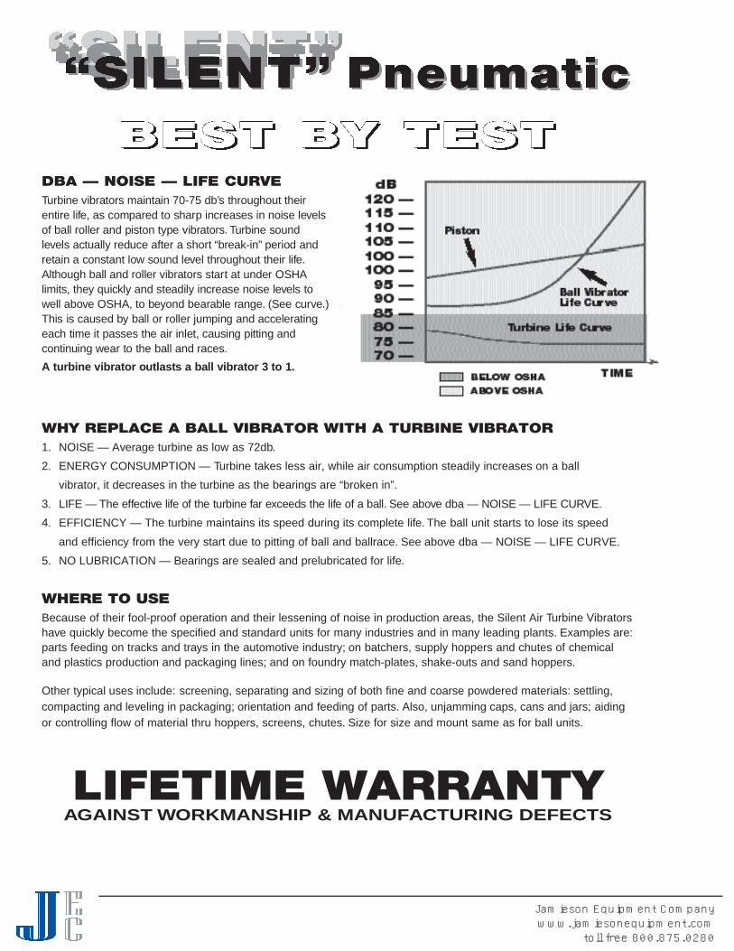
DBA — NOISE — LIFE CURVETurbine vibrators maintain 70-75 db’s throughout theirentire life, as compared to sharp increases in noise leve l sof ball roller and piston type vibra t o r s. Turbine soundl evels actually reduce after a short “ b r e a k - i n ” p e riod andretain a constant low sound level throughout their life.Although ball and roller vibrators start at under OSHAl i m i t s, they quickly and steadily increase noise levels towell above OSHA, to beyond beara ble ra n g e. (See curve. )This is caused by ball or roller jumping and accelera t i n geach time it passes the air inlet, causing pitting andc o n t i nuing wear to the ball and ra c e s.A turbine vibrator outlasts a ball vibrator 3 to 1.
WHY REPLACE A BALL VIBRATOR WITH A TURBINE VIBRATOR1. NOISE — Average turbine as low as 72db.2. ENERGY CONSUMPTION — Turbine takes less air, while air consumption steadily increases on a ball
vibrator, it decreases in the turbine as the bearings are “broken in”.
3 . LIFE — The effe c t i ve life of the turbine far exceeds the life of a ball. See above dba — NOISE — LIFE CURV E .4. EFFICIENCY — The turbine maintains its speed during its complete life. The ball unit starts to lose its speed
and efficiency from the very start due to pitting of ball and ballrace. See above dba — NOISE — LIFE CURVE.5. NO LUBRICATION — Bearings are sealed and prelubricated for life.
WHERE TO USEBecause of their fool-proof operation and their lessening of noise in production areas, the Silent Air Turbine Vibratorshave quickly become the specified and standard units for many industries and in many leading plants. Examples are:parts feeding on tracks and trays in the automotive industry; on batchers, supply hoppers and chutes of chemicaland plastics production and packaging lines; and on foundry match-plates, shake-outs and sand hoppers.
Other typical uses include: screening, separating and sizing of both fine and coarse powdered materials: settling,compacting and leveling in packaging; orientation and feeding of parts. Also, unjamming caps, cans and jars; aidingor controlling flow of material thru hoppers, screens, chutes. Size for size and mount same as for ball units.
LIFETIME WARRANTYAGAINST WORKMANSHIP & MANUFACTURING DEFECTS
Jamieson Equipment Companywww.jamiesonequipment.com
toll free 800.875.0280

SILENT TURBINE VIBRATORS USE 50% LESS AIRTHAN COMPARABLE PNEUMATIC BALL VIBRATORS
VIBCO SILENT TURBINE VIBRATORS CANSAVE UP TO 56% OF THE AIR CONSUMPTIONOF COMPETITIVE BALL VIBRATOR MODELS. See Chart Below
AIR CONSUMPTION A ball vibrator draws up to over 50% more air than a turbinevibrator. The ball in a ball vibrator takes up only 1/20 of availablespace in the housing and the majority of the air pushing the ballaround in the ballrace is wasted and exhausted without producingany work. In a turbine vibrator, the turbine fits snugly in thehousing and only a very minimal amount of air can escapewithout producing any work.
EFFICIENCYThe turbine vibrator has a high level of efficiency throughout it’slife. Ball vibrators immediately lose speed and efficiency due topitting of the ball and ballrace. An added plus to the turbinevibrator is that it is not subject to pitting and the turbine vibratordoes not require airline lubrication like the ball vibrator.
NOISETurbine vibrators maintain 70-75 dB throughout their entire life ascompared to sharp increases in noise levels of ball, roller andpiston vibrators, which can reach up to 100 dB or more.
VIBCOTURBINEMODEL
BVS & VS 100
BVS & VS 130
BVS & VS 160
BVS & VS 190
BVS & VS 250
BVS & VS 320
BVS & VS 380
BVS & VS 440
BVS & VS 510
BVS & VS 570
CFM/ 60 PSI
4
4.5
7
7.5
8
9
16
18
18
21
COMPETITIVEBALL
MODELS*
6
13
16
19
25
32
38
44
51
57
MARTIN
11%
40%
N/A
32%
38.5%
47%
20%
14%
N/A
***54%
COUGAR
11%
40%
N/A
32%
38.5%
47%
20%
14%
20%
N/A
GLOBAL
SAVED CFM BY USINGVIBCO TURBINE VERSUS:**
56%
70%
14.6%
37.5%
55.5%
44%
36%
48.5%
33%
N/A
*Covers ball vibrators **Values taken from published catalogs *** Roller vibrator
PATENTED
A:
B:
Jamieson Equipment Companywww.jamiesonequipment.com
toll free 800.875.0280
TECHNICAL DATA
M o d e lWe i g h t * * *
k g .l b s . C F MSpeed VPMSpeed VPM C F M dB *Max. Lbs.**
Material In BinNl b s . F o rc e80 PSI60 PSI
V S - 1 0 0 7/13 oz. . 1 9 8 / . 3 6 8 1 2 0 0 0 4 2 0 8 9 6 6 2 0 0V S - 1 3 0 11/21 oz. . 3 1 2 / . 5 9 5 8 0 0 0 4 . 5 1 0 5 0 0 5 . 5 7 5 3 3 4 6 7 7 5 0V S - 1 6 0 3 1 . 4 1 0 0 0 0 7 1 2 0 0 0 8 1 6 0 7 1 2 7 0 1 6 0 0V S - 1 9 0 3 . 5 1 . 6 4 2 0 0 7 . 5 7 2 0 0 9 2 7 0 1 2 0 1 7 0 5 0 0 0V S - 2 5 0 5 2 . 3 5 5 0 0 9 7 2 0 0 1 0 . 5 5 0 0 2 2 2 5 7 0 5 0 0 0V S - 3 2 0 6 . 5 2 . 9 5 2 0 0 9 6 8 0 0 1 1 6 0 0 2 6 6 9 6 9 7 0 0 0V S - 3 8 0 1 1 . 5 5 . 2 4 6 0 0 1 6 5 2 0 0 1 7 7 2 5 3 2 2 6 7 2 7 2 5 0V S - 5 1 0 1 5 6 . 8 4 0 0 0 1 8 4 5 0 0 2 1 9 0 0 4 0 0 4 7 7 9 0 0 0
DIMENSIONS M o d e l
V S - 1 0 0V S - 1 3 0V S - 1 6 0V S - 1 9 0V S - 2 5 0V S - 3 2 0V S - 3 8 0V S - 5 1 0
Ai n c h / m m
3 7 64 1 0 24 1 0 24 1 0 24 1 0 24 1 0 2
51/2 1 4 051/2 1 4 0
Bi n c h / m m
C * *i n c h / m m
17/8 4 82 5 127/8 7 331/4 8 335/8 9 24 1 0 243/4 1 2 143/4 1 2 1
Hi n c h / m m
2 5 125/1 6 5 93 7 631/1 6 7 831 1/1 6 9 443/4 1 2 147/8 1 2 453/8 1 3 7
Di n c h / m m
3/8 1 03/8 1 01 1/1 6 1 75/8 1 69/1 6 1 41 3/1 6 2 11 2 51 2 5
Ei n c h / m m
15/1 6 3 311/2 3 817/8 4 821/8 5 421/4 5 721/4 5 727/8 7 331/4 8 3
Fi n c h / m m
1/8 - NPT1/8 - NPT1/4 - NPT1/4 - NPT1/4 - NPT3/8 - NPT3/8 - NPT1/2 - NPT
Gi n c h / m m
11 1/1 6 4 311 5/1 6 4 927/1 6 62 21/2 6 43 7 641/8 1 0 54 1 0 243/4 1 2 1
Li n c h / m m
37/8 9 847/8 1 2 451/8 1 3 057/1 6 1 3 851/2 1 4 051/2 1 4 067/8 1 7 561 5/1 6 1 7 6
Wi n c h / m m
1/4 63/8 1 03/8 1 03/8 1 01/2 1 31/2 1 33/8 1 03/8 1 0
I *i n c h / m m
1 2 511/4 3 215/8 4 113/4 4 417/8 4 823/4 7 021/2 6 427/8 7 3
Ji n c h / m m
3/4 1 91 5/1 6 2 417/1 6 37 15/1 6 3 311/2 3 813/4 4 421/4 5 723/4 7 0
Data obtained on Laboratory test block. Frequency and force will decrease on less rigid mount. Note:Dimensions & data subject to change without notice.* Decibel from A-scale at 1 meter and 80 PSI.N = Centrifugal force in Newton.
** Rule of thumb for sizing “One lb. Vibrator Force”to each 10 lbs. of Bin Content”at 80 PSI.*** Fist Figure Aluminum 2nd - malleable iron.
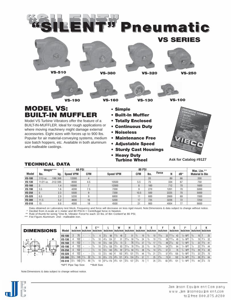
MODEL VS:BUILT-IN MUFFLERModel VS Turbine Vibrators offer the feature of aBUILT-IN-MUFFLER. Ideal for rough applications orwhere moving machinery might damage externalaccessories. Eight sizes with forces up to 900 lbs.Popular for air material-conveying systems, mediumsize batch hoppers, etc. Available in both aluminumand malleable castings.
• Simple• Built-In Muffler• Totally Enclosed• Continuous Duty• Noiseless• Maintenance Free• Adjustable Speed• Sturdy Cast Housings• Heavy Duty
Turbine Wheel
VS SERIES
- -- -- -- -- -- -
11/4 3 213/4 4 4
5/8 1 63/4 1 97/8 2 27/8 2 211/8 29 11/4 3 211/2 3 813/4 4 4
Ki n c h / m m
*NPT Pipe Tap Size **Bolt Size
Ask for Catalog #9127
VS-510 VS-380 VS-320 VS-250
VS-190 VS-130 VS-100VS-160
Note:Dimensions & data subject to change without notice.
Jamieson Equipment Companywww.jamiesonequipment.com
toll free 800.875.0280

BVS SERIES
TECHNICAL DATA
M o d e lWe i g h t * * *
k g .l b s . C F MSpeed VPMSpeed VPM C F M dB *Max. Lbs.**
Material In BinN *l b s . F o rc e80 PSI60 PSI
B V S - 6 0 7/13 oz. . 1 9 8 / . 3 6 8 1 2 0 0 0 4 2 0 8 9 6 6 2 0 0B V S - 1 3 0 10/20 oz. . 2 8 3 / . 5 6 7 8 0 0 0 4 . 5 1 0 5 0 0 5 . 5 7 5 3 3 4 6 7 7 5 0B V S - 1 6 0 3 1 . 4 9 5 0 0 7 1 1 0 0 0 8 1 6 0 7 1 2 7 0 1 6 0 0B V S - 1 9 0 3 . 5 1 . 6 5 5 0 0 7 . 5 7 2 0 0 8 . 5 2 7 0 1 2 0 1 7 1 2 7 0 0B V S - 2 5 0 6 2 . 7 5 2 0 0 8 7 2 0 0 9 4 8 0 2 1 3 6 7 2 4 8 0 0B V S - 3 2 0 8 . 5 3 . 9 5 5 0 0 9 6 8 0 0 1 0 6 0 0 2 6 6 9 7 0 5 3 0 0B V S - 3 8 0 1 3 5 . 8 4 5 0 0 1 6 5 0 0 0 1 8 6 7 0 2 9 8 1 7 4 6 7 0 0B V S - 4 4 0 1 6 7 . 3 4 3 0 0 1 8 4 8 0 0 2 1 7 0 0 3 1 1 4 7 6 7 0 0 0B V S - 5 1 0 1 6 7 . 3 4 0 0 0 1 8 4 5 0 0 2 1 9 0 0 4 0 0 4 7 7 9 0 0 0B V S - 5 7 0 2 3 1 0 . 4 3 6 0 0 2 1 4 0 0 0 2 6 1 0 5 0 4 6 7 1 8 3 1 0 5 0 0
Data obtained on Laboratory test block. Frequency and force will decrease on less rigid mount.Data subject to design changes.* Decibel from A-scale at 1 meter and 80 PSI. N = Centrifugal force in Newton.
** Rule of thumb for sizing “One lb. Vibrator Force”to each 10 lbs. of Bin Content” at 80 PSI.*** Fist Figure Aluminum 2nd - malleable iron.
MODEL BVS:THREADED EXHAUSTVIBCO offers 10 models in the extra heavy duty BVSseries. The use of non-lubricated air supply makes theBVS turbine vibrators perfect for applications in food andpharmaceutical (etc.) industries where oil exhaust wouldbe objectionable. Exhaust port is threaded for piping offof air exhaust in closed, sanitized systems. Extra largeamplitudes and wide range of sizes makes the BVS’sideal for quickly moving parts or materials.
• Quiet, Meets OSHA As Low As 68 dBat 1 Meter
• No Lubrication Require d• Easily Repaired - One Moving Part• Patented Design• High Force Output• Outlasts Piston Vibrators 3 to 1• Oversized Bearings
BVS-570
BVS-510
BVS-380
BVS-320
BVS-250
BVS-190
M o d e l
B V S - 6 0B V S - 1 3 0B V S - 1 6 0B V S - 1 9 0B V S - 2 5 0B V S - 3 2 0B V S - 3 8 0B V S - 4 4 0B V S - 5 1 0B V S - 5 7 0
Ai n c h / m m
31 3/1 6 9 747/8 1 2 451/2 1 4 051/4 1 3 363/4 1 7 163/4 1 7 171 5/1 6 2 0 281 5/1 6 2 2 781 5/1 6 2 2 71 03/1 6 2 5 9
C * *i n c h / m m
3/4 1 97/8 2 213/8 3 515/1 6 3 315/8 4 115/8 4 12 5 123/1 6 5 621/4 5 721 5/1 6 7 5
Li n c h / m m
Di n c h / m m
15/8 4 117/8 4 827/8 7 333/1 6 8 139/1 6 9 04 1 0 243/4 1 2 143/4 1 2 143/4 1 2 157/1 6 1 3 8
Ei n c h / m m
11/4 3 217/1 6 3 717/8 4 817/8 4 825/1 6 5 923/4 7 03 7 637/1 6 8 737/1 6 8 74 1 0 2
Fi n c h / m m
1/4 63/8 1 03/8 1 03/8 1 01/2 1 31/2 1 35/8 1 65/8 1 65/8 1 63/4 1 9
Gi n c h / m m
1/8 - NPT1/8 - NPT1/4 - NPT1/4 - NPT1/4 - NPT3/8 - NPT3/8 - NPT1/2 - NPT1/2 - NPT3/4 - NPT
I *i n c h / m m
1/8 - NPT1/4 - NPT3/8 - NPT3/8 - NPT3/8 - NPT1/2 - NPT1/2 - NPT3/4 - NPT3/4 - NPT1 - NPT
Wi n c h / m m
3 7 64 1 0 24 1 0 24 1 0 25 1 2 75 1 2 76 1 5 27 1 7 87 1 7 88 2 0 3
Hi n c h / m m
5/8 1 65/8 1 69/1 6 1 47/8 2 27/8 2 211/8 2 911/8 2 913/1 6 3 011/4 3 21 2 5
J *i n c h / m m
13/1 6 3 011/4 3 211 1/1 6 4 319/1 6 4 017/8 4 821/4 5 721 1/1 6 6 827/1 6 6 229/1 6 6 531/8 7 9
DIMENSIONS
BVS-130
27/1 6 6 225/8 6 735/8 9 237/1 6 8 731 5/1 6 1 0 047/8 1 2 451 3/1 6 1 4 853/4 1 4 653/4 1 4 671/4 1 8 4
PATENTED
*NPT Pipe Tap Size **Bolt SizeNote:Dimensions & data subject to change without notice.
Jamieson Equipment Companywww.jamiesonequipment.com
toll free 800.875.0280

The NEW Millennium Line of Sanitary Pneumatic Tu r b i n e(M LT / M H I) V i b rators is your solution for all steri l e / c l e a na p p l i c a t i o n s. The line consists of the MLT & MHI-130, -190,-250 and 320; all are designed for the most adve r s ea p p l i c a t i o n s. Their ex t ruded aluminum housings, stainlesssteel shafts, and aircraft aluminum cove r s, give thesev i b rators additional strength, durability and long life. T h eyare also designed with slotted mounting holes for easyinstallation on many bolt patterns and tapped exhaust port sthat allow exhausting air to be piped off to insure a cleane nv i r o n m e n t . These units can be supplied with a va riety ofs a n i t a ry finishes such as: high gloss dairy white industri a lenamel, anodized or unpainted aluminu m .
Ideal for applications in industries that require a sanitaryv i b ra t o r. Such industries include: food, beve ra g e, andp h a rmaceutical industri e s.
Model MLT-250, as part of the millennium Turbine Line ofV i b rators has high speed sealed bearings that arep r e - l u b ricated for life making them maintenance free. T h eyh ave an operating range of 30-80 PSI and a maximu mo p e rating temperature of 250°F or 120°C. Decibel readingswell below OSHA limits, as low as 68dB on A-scale at 1meter with no more sound than an electric motor. T h epatented millennium turbine vibrator draws 50% less airthan a compara ble ball vibrator and lasts three timesl o n g e r. L i ke the rest of V I B C O ’s products these are 100%made in the USA and competitively pri c e d .
MODEL MLTSS & MHISS -130, -190, -320– Stainless Steel Pneumatic Turbine Vibrators areconstructed of 303 Stainless, specifically made for anysanitary application found in the pharmaceutical, foodand beverage or other caustic chemical typeenvironments, like the plating industry. The MLTSS &MHI vibrators are totally enclosed and wash down safe.No lubrication is necessary as the bearings are pre-lubricated for life, making them maintenance FREE.Exhausting air can either be muffled or ported to anoutside location preserving a sanitary environment.
Advantages of the MLTSS & MHISS line of sanitaryvibrators include:• Non-corroding housing• Wash down safe clean flat surface makes for easy
wipe down• Lowest noise levels in the industry, no more
sound than an electric motor 68-75 dB• Air consumption at 50% less than
comparable ball vibrators• 100% made in the USA, ships from STOCK
Operating pressure is 30-80 PSI with a maximumoperating temperature of 250F or 120C.
MODEL MLT & MHISANITARY TURBINE• IDEAL FOR SANITARY
APPLICATIONS EVEN IN HARSHCHEMICAL ENVIRONMENTS
• MANY DIFFERENT SANITARYFINISHES AVAILABLE
MODEL MLTSS & MHISSSTAINLESS STEEL• CONSTRUCTED OF 303
STAINLESS STEEL
• COMPLETELY MADE IN USA WITHVIBCO’s PATENTED DESIGN
SANITARY MLT SERIES
The MLT & MLTSS are designed for continuous duty at up to 80 PSI and have heavy duty bearings for long life.
The MHI & MHISS Lines are designed to produce high frequency and maximum fo r c e s. I n t e rmittent duty only.(30 seconds max. c o n t i nuous ru n n i n g . Running time equal to or less than off time. )
MLT-130MHI-130
MLT-250MHI-250
MLT-320MHI-320
MLT-190MHI-190
MLTSS-130MHISS-130
MLTSS-320MHISS-320
MLTSS-130MHISS-130
Jamieson Equipment Companywww.jamiesonequipment.com
toll free 800.875.0280

MLTSS/MHISS
STAINLESS STEELAND MLT SERIES
PATENTED
TECHNICAL DATA
WEIGHT 60 PSI*** 80 PSI***
MODEL lbs. kg. Speed VPM* CFM Force (lbs.) Force(N) Speed VPM* CFM Force (lbs.) Force (N) dB****
MLT-130 1 .45 8600 4.5 50 225 10500 5.5 75 334 68MLTSS-130 2 .9MLT-190 2 .91 5500 7.5 160 710 7200 8.5 270 1200 71MLTSS-190 7 3.2MLT-250 2.4 1.08 5200 8 250 1115 7200 9 480 2136 72MLT-320 4.5 2.04 5500 9 390 1740 6800 10 600 2669 70MLTSS-320 13 6.0MHI-130 1 .45 17200 4.5 200 890 21000 5.5 300 1340 68MHISS-130 2 .9MHI-190 2 .91 8000 7.5 335 1490 10500 8.5 575 2560 71MHISS-190 7 3.2MHI-250 2.4 1.08 7400 8 510 2270 10200 9 965 9290 72MHI-320 4.5 2.04 7200 9 675 3000 10000 10 1300 5780 70MHISS-320 13 6.0
* Vibrations per minute N = Centrifugal force in Newtons*** Test data are close to actual performance data of the unit on a typical application.The data obtained on a heavy laboratory test block cannot be duplicated on a typical
application. We feel it is more important for the customer to measure the actual frequency of the unit on the application and know the unit is performing to specificationsthan not knowing what performance path to expect, or worse believing the test block data should be obtained.
****Decibel from A-scale at 1 meter and 80 PSI Note:Dimensions & data subject to change without notice.
TECHNICAL HIGHLIGHTS• Pressure range 30 to 80 PSI• Operating temp. max 250°F, 120°C• Decibel level as low as 68 dB on A-scale at 1 meter• Air consumption 50% less than comparable ball vibrators• Bearings are prelubricated for life
A B C D E F G H I J Kinch/mm inch/mm inch/mm inch/mm inch/mm inch/mm inch/mm inch/mm inch/mm Inlet Outlet
MLT-130 & MHI-130 3-1/2 89 1 25 2-1/2 64 2-3/4 70 1/2 13 1-3/8 35 1-7/16 37 1/4 6 1/8-28NPT 1/4-18NPT 1-7/8 48
MLT-190 & MHI-190 4-1/2 114 1-13/16 46 3-3/16 81 3-1/2 89 5/8 16 1-11/16 43 1-15/16 49 3/8 10 1/4-18NPT 3/8-18NPT 3-3/8 86
MLT-250 & MHI-250 5 127 2 51 3-3/8 86 4 102 5/8 16 1-11/16 43 2-1/4 57 3/8 10 1/4-18NPT 3/8-18NPT 3-1/2 89
MLT-320 & MHI-320 6-3/8 162 2 51 4-1/4 108 5 127 13/16 21 2-3/16 56 2-13/16 71 1/2 12 3/8-18NPT 1/2-14NPT 4 4
MLTSS-130 & MHISS-130 3-1/2 89 1 25 2-3/8 60 2-3/4 70 – 1-3/16 30 1-7/16 37 1/4 6 1/8-28NPT 1/4-18NPT 1-7/8 48
MLTSS-190 & MHISS-190 4-1/2 114 1-3/4 44 3-1/2 89 3-1/2 89 – 1-3/4 44 1-15/16 50 3/8 10 1/4-18NPT 3/8-18NPT 3-3/8 86
MLTSS-320 & MHISS-320 6 152 2 51 4-1/4 108 5 127 – 2-1/8 55 2-13/16 71 1/2 12 3/8-18NPT 1/2-14NPT 4 102
*Bolt Size Note:Dimensions & data subject to change without notice.
DIMENSIONS
MLT/MHI
Jamieson Equipment Companywww.jamiesonequipment.com
toll free 800.875.0280
CCF-2000CCF-4000
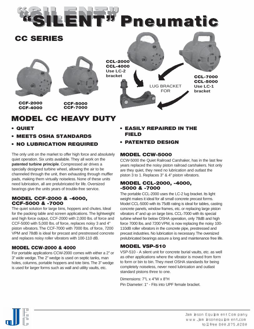
The only unit on the market to offer high force and absolutelyquiet opera t i o n . Six units ava i l a bl e. T h ey all wo rk on thepatented turbine principle. Compressed air dri ves aspecially designed turbine wheel, allowing the air to bechanneled through the unit, then exhausting through mu f f l e rp a d s, making them virtually noiseless. None of these unitsneed lubrication, all are prelubricated for life. O ve r s i ze db e a rings give the units years of trouble-free serv i c e.
MODEL CCF-2000 & -4000,CCF-5000 & -7000The quiet solution for large bins, hoppers and chutes. I d e a lfor the packing table and screen applications. The lightwe i g h tand high force output, CCF-2000 with 2,000 lbs. of force andCCF-5000 with 5,000 lbs. of fo r c e, replaces noisy 3 and 4"piston vibra t o r s. The CCF-7000 with 7000 lbs. of fo r c e, 7200VPM and 78dB is ideal for precast and prestressed concreteand replaces noisy roller vibrators with 100-110 dB.
MODEL CCW-2000 & 4000For port a ble applications CCW-2000 comes with either a 2” o r3 ” wide we d g e. The 2” wedge is used on septic tanks, manh o l e s, columns, port a ble hoppers and tote bins. The 3” we d g eis used for larger fo rms such as wall and utility va u l t s, etc.
• QUIET
• MEETS OSHA STANDARDS
• NO LUBRICATION REQUIRED
• EASILY REPAIRED IN THEFIELD
• PATENTED DESIGN
MODEL CCW- 5 0 0 0C C W-5000 the Quiet Railroad Carshake r, has in the last fewyears replaced the noisy piston railroad carshake r s. Not onlyare they quiet, they need no lubrication and outlast thepiston 3 to 1. Replaces 3" & 4” piston vibra t o r s.
MODEL CCL-2000, -4000,-5000 & -7000The port a ble CCL-2000 uses the LC-2 lug bra cke t . Its lightweight makes it ideal for all small concrete precast fo rm s.Model CCL-5000 with its 75dB rating is ideal for tabl e s, castingconcrete panels, window fra m e s, etc. or replacing large pistonv i b rators 4” and up on large bins. CCL-7000 with its specialturbine wheel for below OSHA operation, only 78dB and highforce 7000 lbs. and 7200 VPM, is now replacing the noisy 100-110dB roller vibrators in the concrete pipe, prestressed andprecast industri e s. No lubrication is necessary.The ove r s i ze dp r e l u b ricated bearings assure a long and maintenance free life.
MODEL VSP-510VSP-510 - A silent unit for concrete bu rial va u l t s, etc. as we l las other applications where the vibrator is moved from fo rmto fo rm or bin to bin. T h ey meet OSHA standards for beingcompletely noiseless, never need lubrication and outlaststandard pistons three to one.
D i m e n s i o n s : 7"L x 4"W x 8"HPin Diameter: 1" - Fits into UPF female bra cke t .
CC SERIES
MODEL CC HEAVY DUTY
CCL-7000CCL-5000Use LC-1bracket
CCF-5000CCF-7000
LUG BRACKETFOR
CCL-2000CCL-4000Use LC-2bracket
Jamieson Equipment Companywww.jamiesonequipment.com
toll free 800.875.0280

C C F, CCL & CCW- 2 0 0 0 2 3 1 0 . 5 4 0 0 0 3 0 6 0 0 0 4 0 2 0 0 0 8 9 9 8 7 8 2 0 0 0 0C C F, CCL & CCW- 4 0 0 0 2 3 1 0 . 5 4 0 0 0 3 0 6 0 0 0 4 0 4 0 0 0 1 7 9 9 6 7 8 4 0 0 0 0CCF & CCL-5000 4 8 2 1 . 8 4 0 0 0 3 5 6 0 0 0 5 0 5 0 0 0 2 2 2 4 5 7 5 5 0 0 0 0C C W- 5 0 0 0 4 8 2 1 . 8 5 0 0 0 4 0 7 2 0 0 5 0 7 0 0 0 3 1 1 4 3 7 8 7 0 0 0 0CCF & CCL-7000 4 8 2 1 . 8 5 0 0 0 4 0 7 2 0 0 5 0 7 0 0 0 3 1 1 4 3 7 8 7 0 0 0 0V S P - 5 1 0 1 5 6 . 8 4 0 0 0 1 8 4 5 0 0 2 1 1 0 0 0 4 0 0 4 7 7 9 0 0 0
C C F C C W- 2 0 0 0 , 4 0 0 0 C C L C C W- 5 0 0 0
*NPT Pipe Tap Size **Bolt Size Note:Dimensions & data subject to change without notice.
M o d e lA
i n c h / m m6 1 5 2- -- -- -8 2 0 3- -- -
2 5 1- -- -- -31/8 7 9- -- -
71/2 1 9 17 1 7 87 1 7 87 1 7 81 01/4 2 6 093/8 2 3 893/4 2 4 8
81/1 6 2 0 581/1 6 2 0 581/1 6 2 0 581/1 6 2 0 585/8 2 1 985/8 2 1 985/8 2 1 9
71/8 1 8 171/4 1 8 48 2 0 38 2 0 387/8 2 2 585/8 2 1 985/8 2 1 9
51/1 6 1 2 951/1 6 1 2 951/1 6 1 2 951/1 6 1 2 961/1 6 1 5 461/1 6 1 5 461/1 6 1 5 4
C * *i n c h / m m
Li n c h / m m
Di n c h / m m
Ei n c h / m m
Fi n c h / m m
Gi n c h / m m
I *i n c h / m m
Wi n c h / m m
Hi n c h / m m
C C F - 2 0 0 0 & 4 0 0 0
C C L - 2 0 0 0 & 4 0 0 0
C C W- 2 0 0 0
C C W- 4 0 0 0
C C F - 5 0 0 0 & 7 0 0 0
C C L - 5 0 0 0 & 7 0 0 0
C C W- 5 0 0 0
DIMENSIONS
5/8 1 6- -- -- -3/4 1 9- -- -
13/4 4 441/8 1 0 551 5/1 6 1 5 155/1 6 1 5 127/8 7 351/4 1 3 345/8 1 1 7
3/4 - NPT3/4 - NPT3/4 - NPT3/4 - NPT1 - NPT1 - NPT1 - NPT
HEAVY DUTYSERIES
VSP-510
CCW-2000 on distribution boxes CCW-5000 railroad car shaker VSP-510 on burial vault forms
Max. Lbs.**Material in BinN * d B *C F MSpeed VPMSpeed VPM l b s .
F o rc eC F Mk g .l b s .M o d e l
We i g h t60 PSI 80 PSI
Data obtained on Laboratory test block. Frequency and force will decrease on less rigid mount. Note:Dimensions & data subject to change without notice.* Decibel from A-scale at 1 meter and 80 PSI. N = Centrifugal force in Newton.** Rule of thumb for sizing “One lb. Vibrator Force”to each 10 lbs. of Bin Content”at 80 PSI.
TECHNICAL DATA UPF
CCW-5000 RAILROADCARSHAKER
CCW-20002” WedgeCCW-40003” Wedge
UWF-1 for 2” WedgeUWF-3 for 3” Wedge
J *i n c h / m m
Ki n c h / m m
Mi n c h / m m
- -6 1 5 2- -- -- -8 2 0 3- -
------
3/4 - NPT
53/8 1 3 73/4 1 921/4 5 731/8 7 961/4 1 5 911/4 3 251/2 1 4 0
3/4 1 93/8 1 07/8 2 27/8 2 211/8 2 91 3/1 6 2 111/8 2 9
PATENTED
FemaleBrackets
Jamieson Equipment Companywww.jamiesonequipment.com
toll free 800.875.0280

VS-250 on transfer chute VS-190 on test table FBS-190 on molding machine
BBS-160BBS-190
BBS-130 BBS-100 FBS-160FBS-190
FBS-130 FBS-100
MODEL BBS & FBSBBS-100, 130, 160 and 190 - smallest of VIBCO turbinevibrators; with versatile mount and aluminum* housing.Never needs oil for continuous duty operation. TheFBS-100, 130, 160 and 190 are designed especially
TECHNICAL DATA
M o d e lWe i g h t * * *
k g .l b s . C F MSpeed VPMSpeed VPM C F M d B *Max. Lbs.**
Material In BinNl b s . F o rc e80 PSI60 PSI
B B S - 1 0 0 5 oz. . 1 4 2 1 2 0 0 0 3 . 5 2 0 8 9 6 6 2 0 0B B S - 1 3 0 9 oz. . 2 5 5 8 0 0 0 4 . 5 1 0 5 0 0 5 . 5 7 5 3 3 4 6 7 7 5 0B B S - 1 6 0 12 oz. . 3 4 0 5 5 0 0 5 9 0 0 0 7 1 6 0 7 1 2 6 7 1 6 0 0B B S - 1 9 0 15 oz. . 4 2 5 8 5 0 0 5 1 0 0 0 0 7 2 5 0 1 1 1 2 7 0 2 5 0 0
F B S - 1 0 0 10.5 oz. . 2 9 8 1 5 0 0 0 5 3 0 1 3 3 6 6 For Match-PlatesF B S - 1 3 0 16 oz. . 4 5 4 1 3 0 0 0 6 1 5 0 0 0 7 1 5 0 6 6 7 6 8 For Match-PlatesF B S - 1 6 0 24 oz. . 6 8 0 1 0 5 0 0 6 1 3 0 0 0 7 2 2 5 1 0 0 1 6 8 For Match-PlatesF B S - 1 9 0 26 oz. . 7 3 7 8 5 0 0 6 1 0 0 0 0 8 2 5 0 1 1 1 2 7 0 For Match-Plates
Data obtained on Laboratory test block. Frequency and force will decrease on less rigid mount.Note:Dimensions & data subject to change without notice.
* Decibel from A-scale at 1 meter and 80 PSI. N = Centrifugal force in Newton.** Rule of thumb for sizing “One lb. Vibrator Force”to each 10 lbs. of Bin Content”at 80 PSI.
*NPT Pipe Tap Size **Bolt Size Note:Dimensions & data subject to change without notice.
M o d e lA
i n c h / m m
25/8 6 7
33/1 6 8 1
39/1 6 9 0
1/8 - NPT
1/4 - NPT
1/4 - NPT
31/4 8 3
33/4 9 5
41/8 1 0 5
15/8 4 1
17/8 4 8
2 5 1
5/1 6 8
3/8 1 0
3/8 1 0
9/1 6 1 4
5/8 1 6
3/4 1 9
1 2 5
13/1 6 3 0
11/4 3 2
C * *i n c h / m m
Li n c h / m m
Di n c h / m m
Ei n c h / m m
Gi n c h / m m
I *i n c h / m m
Wi n c h / m m
Hi n c h / m m
B B S - 1 0 0F B S - 1 0 0B B S - 1 3 0F B S - 1 3 0B B S - 1 6 0 & 1 9 0F B S - 1 6 0 & 1 9 0
BBS SERIESFBS SERIES
as a match plate vibrator for the foundry industry.For fast start, high RPM and force and low noise with abuilt-in muffler. The match plate vibrators to be used onlyfor intermittent duty.
*Malleable casting available on special order.
2 5 1
21/4 5 7
29/1 6 6 5
5/1 6 8
5/1 6 8
5/1 6 8
DIMENSIONS
Jamieson Equipment Companywww.jamiesonequipment.com
toll free 800.875.0280

Small SILENT Turbine mounted to automated partsalignment track. Helps keep parts moving freely.
SILENT Turbines mounted on a track to consolidate pillsin bottles while filling.
SILENT Turbine mounted to a fly ash chute to keepash flowing.
Two SILENT Turbines on a bin with chemicals to helpstop bridging.
Two small SILENT Turbines mounted to cement hopper. Big SILENT Turbine on a table to insure full capacitypackaging of 55 gallon drums.
Jamieson Equipment Companywww.jamiesonequipment.com
toll free 800.875.0280
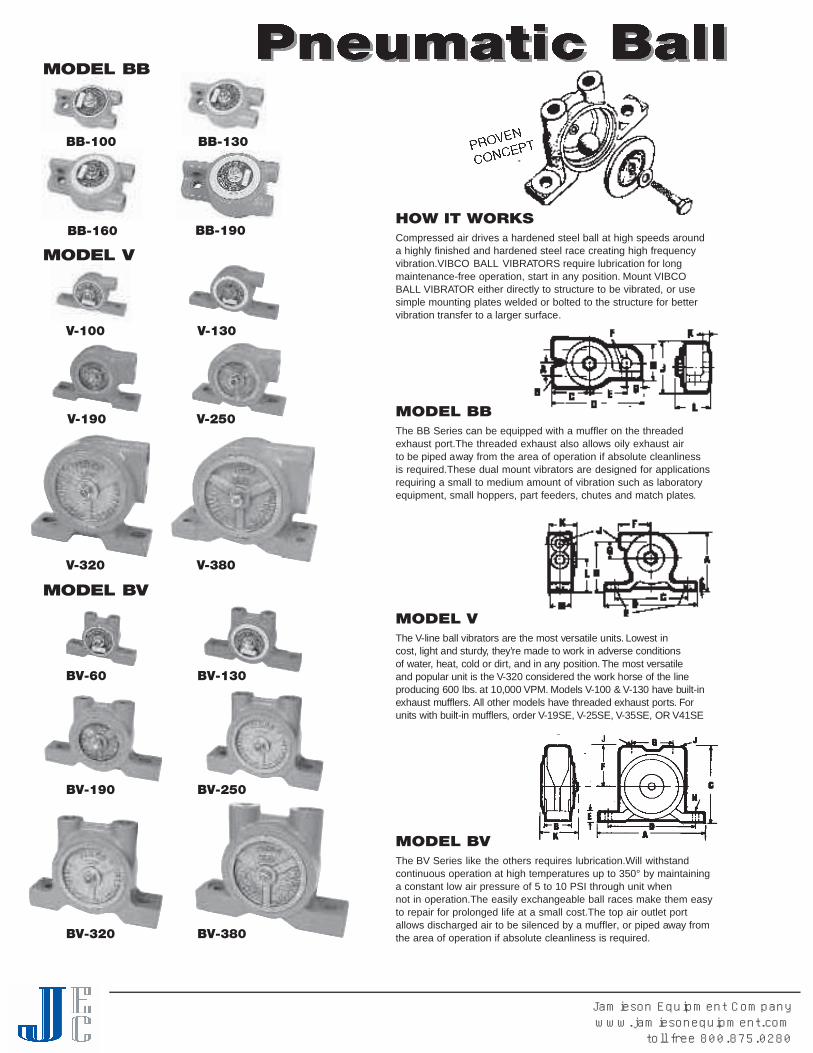
HOW IT WORKSCompressed air drives a hardened steel ball at high speeds arounda highly finished and hardened steel race creating high frequencyvibration.VIBCO BALL VIBRATORS require lubrication for longmaintenance-free operation, start in any position. Mount VIBCOBALL VIBRATOR either directly to structure to be vibrated, or usesimple mounting plates welded or bolted to the structure for bettervibration transfer to a larger surface.
MODEL BBThe BB Series can be equipped with a muffler on the threadedexhaust port.The threaded exhaust also allows oily exhaust airto be piped away from the area of operation if absolute cleanlinessis required.These dual mount vibrators are designed for applicationsrequiring a small to medium amount of vibration such as laboratoryequipment, small hoppers, part feeders, chutes and match plates.
MODEL VThe V-line ball vibrators are the most versatile units. L owest incost, light and sturdy, they ’re made to wo rk in adverse conditionsof wa t e r, heat, cold or dirt, and in any position. The most ve r s a t i l eand popular unit is the V-320 considered the wo rk horse of the lineproducing 600 lbs. at 10,000 V P M . Models V-100 & V-130 have bu i l t - i nexhaust mu f f l e r s. All other models have threaded exhaust port s. Fo runits with built-in mu f f l e r s, order V-19SE, V-25SE, V-35SE, OR V 4 1 S E
MODEL BVThe BV Series like the others requires lubrication.Will withstandcontinuous operation at high temperatures up to 350° by maintaininga constant low air pressure of 5 to 10 PSI through unit whennot in operation.The easily exchangeable ball races make them easyto repair for prolonged life at a small cost.The top air outlet portallows discharged air to be silenced by a muffler, or piped away fromthe area of operation if absolute cleanliness is required.
BB-100 BB-130
V-100
V-250V-190
V-320 V-380
BV-60 BV-130
BV-190 BV-250
BV-320 BV-380
V-130
MODEL BB
MODEL V
J
MODEL BV
BB-160 BB-190
Jamieson Equipment Companywww.jamiesonequipment.com
toll free 800.875.0280

B B - 1 0 0 8 oz. . 2 2 7 1 7 0 0 0 2 2 0 0 0 0 4 2 4 0 0 0 6 5 5 2 4 5 7 5 / 2 0 0 0 0 5 5 0
B B - 1 3 0 10 oz . 2 8 3 1 2 0 0 0 2 . 5 1 5 0 0 0 5 1 9 0 0 0 7 . 5 8 0 3 5 6 7 2 / 1 5 0 0 0 8 0 0
B B - 1 6 0 16 oz. . 4 5 4 1 1 0 0 0 3 1 3 0 0 0 6 1 5 0 0 0 8 1 4 0 6 2 3 7 6 / 1 3 0 0 0 1 4 0 0
B B - 1 9 0 18 oz. . 5 1 0 1 0 0 0 0 4 1 2 0 0 0 7 1 5 5 0 0 1 1 2 5 0 1 1 1 2 7 7 / 1 2 0 0 0 2 5 0 0
B V- 6 0 8 oz. . 2 2 7 1 7 0 0 0 2 2 0 0 0 0 4 2 4 0 0 0 6 5 5 2 4 5 7 5 / 2 0 0 0 0 5 5 0
B V- 1 3 0 11 oz . 3 1 2 1 2 0 0 0 2 1 5 0 0 0 5 1 9 0 0 0 7 . 5 8 0 3 5 6 7 6 / 1 5 0 0 0 8 0 0
B V- 1 9 0 24 oz. . 6 8 9 1 2 0 0 0 6 1 4 0 0 0 1 0 1 6 0 0 0 1 1 2 6 0 1 1 5 7 7 7 / 1 2 0 0 0 2 6 0 0
B V- 2 5 0 2 . 8 1 . 3 9 2 0 0 8 1 0 5 0 0 1 1 1 1 0 0 0 1 3 3 8 0 1 6 9 1 7 9 / 9 2 0 0 3800
B V- 3 2 0 4 . 8 2 . 2 6 5 0 0 9 7 5 0 0 1 4 8 4 0 0 1 7 4 8 0 2 1 3 6 8 0 / 6 5 0 0 4 8 0 0
B V- 3 8 0 6 . 2 2 . 8 5 5 0 0 1 0 6 2 0 0 1 5 6 5 0 0 2 0 6 0 0 2 6 6 9 8 2 / 5 5 0 0 6 0 0 0
V- 1 0 0 8 oz. . 2 2 7 2 0 0 0 0 4 2 4 0 0 0 6 _ _ 5 5 2 4 5 7 5 / 2 0 0 0 0 5 5 0
V- 1 3 0 11 oz . 3 1 2 1 5 0 0 0 5 1 9 0 0 0 7 . 5 _ _ 8 0 3 5 6 7 2 / 1 5 0 0 0 8 0 0
V- 1 9 0 26 oz. . 7 3 7 1 2 0 0 0 6 1 4 0 0 0 1 0 1 6 0 0 0 1 1 2 6 0 1 1 5 7 7 3 / 1 6 0 0 0 2 6 0 0
V- 2 5 0 2 . 6 1 . 2 9 2 0 0 8 1 0 5 0 0 1 1 1 1 0 0 0 1 3 3 8 0 1 6 9 1 7 2 / 1 1 0 0 0 3 8 0 0
V- 3 2 0 4 . 6 2 . 1 7 5 0 0 1 2 8 9 0 0 1 4 1 0 0 0 0 1 7 6 5 0 2 8 9 2 7 8 / 1 0 0 0 0 6 5 0 0
V- 3 8 0 6 . 2 2 . 8 5 5 0 0 1 0 6 2 0 0 1 5 6 5 0 0 2 0 6 0 0 2 6 6 9 7 8 / 6 5 0 0 6 0 0 0
• S I M P L E• B U I LT- I N - M U F F L E R• R E M O VABLE RACE FOR
EASY MAINTENANCE• HIGH TEMPERATURE OPERAT I O N
TECHNICAL DATA
M o d e lWe i g h t
k g .l b s . C F MSpeed VPMSpeed VPM C F M d B * / V P MMax. Lbs.**
Material In BinNl b s . F o rc e60 PSI20 PSI
Data obtained on Laboratory test block. Frequency and force will decrease on less rigid mount.* Decibel from A-scale at 1 meter. N = Centrifugal force in Newton.** Rule of thumb for sizing “One lb. Vibrator Force”to each 10 lbs. of Bin Content”at 80 PSI.
Note:Dimensions & data subject to change without notice.
40 PSI
C F MSpeed VPM
M O D E L
B B - 1 0 0
B B - 1 3 0
B B - 1 6 0
B B - 1 9 0
B *i n c h
1/8 - N P T1/4 - N P T1/4 - N P T1/4 - N P T
Di n c h / m m
31/4 8 3
33/4 9 5
41/8 1 0 5
41/8 1 0 5
Ei n c h / m m
13/8 3 5
19/1 6 4 0
11 3/1 6 4 6
11 3/1 6 4 6
F * *i n c h / m m
5/1 6 83/8 1 03/8 1 03/8 1 0
Gi n c h / m m
1/2 1 29/1 6 1 45/8 1 65/8 1 6
Hi n c h / m m
1 2 5
13/1 6 3 0
11/4 3 2
11/4 3 2
DIMENSIONSC
i n c h / m m
11/4 3 2
15/8 4 1
13/4 4 4
13/4 4 4
Ji n c h / m m
2 5 1
21/4 5 7
29/1 6 6 5
29/1 6 6 5
Ki n c h / m m
5/1 6 85/1 6 83/8 1 03/8 1 0
Li n c h / m m
19/1 6 4 0
11 5/1 6 4 9
2 5 1
2 5 1
Ai n c h / m m
9/1 6 1 45/8 1 63/4 1 93/4 1 9
M O D E L
V- 1 0 0
V- 1 3 0
V- 1 9 0
V- 2 5 0
V- 3 2 0
V- 3 8 0
Bi n c h / m m
7/1 6 1 17/1 6 1 19/1 6 1 49/1 6 1 43/4 1 97/8 2 2
Di n c h / m m
37/8 9 8
47/8 1 2 4
51/1 6 1 2 9
59/1 6 1 4 1
59/1 6 1 4 1
67/8 1 7 5
E * *i n c h / m m
1/4 63/8 1 03/8 1 01/2 1 21/2 1 23/8 1 0
Fi n c h / m m
15/1 6 3 3
11/2 3 8
2 5 1
21/4 5 7
23/8 6 0
27/8 7 3
Gi n c h / m m
5/8 1 63/4 1 97/8 2 2
11/8 2 9
13/8 3 5
11/2 3 8
Hi n c h / m m
11 1/1 6 4 3
11 5/1 6 4 9
25/8 6 7
21 5/1 6 8 7
41/8 1 0 5
37/8 9 8
Ci n c h / m m
3 7 6
4 1 0 2
4 1 0 2
4 1 0 2
4 1 0 2
51/2 X 11/4
1 4 0 X 3 2
J *i n c h
1/8 - N P T1/8 - N P T1/4 - N P T1/4 - N P T3/8 - N P T3/8 - N P T
Ki n c h / m m
11 1/1 6 4 3
11 5/1 6 4 9
23/1 6 5 6
27/1 6 6 2
23/4 7 0
21 5/1 6 7 5
Li n c h / m m
1 2 5
11/4 3 2
13/4 4 4
17/8 4 8
23/4 7 0
21/2 6 4
Ai n c h / m m
2 5 1
25/1 6 5 9
33/1 6 8 1
31/2 8 9
47/8 1 2 4
47/8 1 2 4
Mi n c h / m m
3/4 1 91 5/1 6 2 4
15/1 6 3 3
11/2 3 8
11/2 3 8
23/8 6 0
80 PSI40 PSI 60 PSI
M O D E L
B V- 6 0
B V- 1 3 0
B V- 1 9 0
B V- 2 5 0
B V- 3 2 0
B V- 3 8 0
Bi n c h / m m
3/4 1 97/8 2 2
11/4 3 2
15/1 6 3 3
15/8 4 1
2 5 1
Di n c h / m m
3 7 6
4 1 0 2
4 1 0 2
5 1 2 7
5 1 2 7
6 1 5 2
Ei n c h / m m
5/8 1 63/4 1 99/1 6 1 47/8 2 2
11/8 2 9
11/8 2 9
Fi n c h / m m
11/4 3 2
15/1 6 3 3
2 5 1
21/8 5 4
29/1 6 6 5
3 7 6
Gi n c h / m m
11/4 3 2
17/1 6 3 7
17/8 4 8
23/1 6 5 6
23/4 7 0
21 3/1 6 7 1
H * *i n c h / m m
1/4 63/8 1 03/8 1 01/2 1 21/2 1 25/8 1 6
Ci n c h / m m
21/2 6 4
23/4 7 0
39/1 6 9 0
31 5/1 6 1 0 0
47/8 1 2 4
53/4 1 4 6
I *i n c h
1/8 - N P T1/8 - N P T1/4 - N P T1/4 - N P T3/8 - N P T3/8 - N P T
J *i n c h / m m
1/8 - N P T1/4 - N P T1/4 - N P T1/4 - N P T3/8 - N P T3/8 - N P T
Ki n c h / m m
11 1/1 6 4 3
11 5/1 6 4 9
21/4 5 7
27/1 6 6 2
23/4 7 0
21 5/1 6 7 5
Ai n c h / m m
37/8 9 8
47/8 1 2 4
51/2 1 4 0
63/4 1 7 1
61 1/1 6 1 7 0
77/8 2 0 0
*NPT Pipe Tap Size **Bolt Size Note:Dimensions & data subject to change without notice.
Jamieson Equipment Companywww.jamiesonequipment.com
toll free 800.875.0280

ONE PIECE DESIGN• LOW COST
• O N LY 3 PA RT SVIBCO is the only company featuring both the One Piece Design andthe All Steel Models. The one piece housing makes the unit low incost but still maintaining high quality and long life. The one piecedesign is the choice for general applications.
ALL STEEL MODELS
• B O LT ISOLATION DESIGNFOR LONGER LIFE
• I M PACTING IN BOTH UP& DOWN STROKE
VIBCO’s steel units can take more abuse, operate longer with minimallubrication, and have a longer life expectancy than the one piecedesign units. The all steel units should be used in continuous dutyapplications and where long life and high reliability is a must.
MODEL 50 & 55 STANDARD IMPACT PISTON VIBRATORS:Most popular piston series because its high impact, linear force andefficient energy transfer assures the flow of materials through bins,chutes, weigh batchers, compacts powdered and viscous materials incontainers and forms;activates screens and precipitators.Successfully used in thousands of applications in mining, chemical,plastics, concrete products, foundry, steel and paper industries.
EXHAUST SILENCER & DUSTPROOFER: For Silent & LongStroke Silent Units. A useful accessory that both reduces exhaustnoise and protects working parts of vibrator in dusty atmospheres forlower maintenance and prolonged life. Threaded exhaust is ideal forclosed sanitary system.
MODEL 50-S & 55-S SILENT OPERATING PISTONVIBRATORS: In areas where noise is objectionable VIBCO Model Sshould be used. Quiet because piston impact is eliminated by cushionof air at both ends. High thrust oscillatory action permits operationeven at low air pressures. When Silent models are used in place ofImpact units use the next larger size.
MODEL 50-L LONG STROKE PISTON VIBRAT O R S : The probl e ms o l vers! Extra-long bodies for high amplitude, high force and lowe rfrequency vibra t i o n . The larger shake is best for moving fluffy, lowdensity and wet or sticky materi a l s. Especially suited for packaging ands c r e e n i n g . Ava i l a ble in 2” and 3” piston size s. Model 50-LS - Air-Cushioned Model. Silent models also ava i l a ble with silencer &d u s t p r o o fe r.
MODEL 50-2EP EXTENDED PISTON VIBRATORS: E x t e n d e dPiston has a 5/8” s t r o ke and threaded extension for attaching rods orbu m p e r s. The air cushioned piston operates quietly at 2400 VPM, 60 PSI& 8 CFM. Ideal for use on port a ble tote or hoppers.
MODEL 50-LI HIGH ENERGY IMPACTORS: All are ava i l a ble in1-1/4, 2 & 3” piston size s. The piston impact is adjustable by regulatingand controlling the air pressure through a timer and solenoid. P i s t o nimpacts can be regulated. The LI-impactors are low in operating costand used in continuous production applications to move materi a lu n i n t e r rupted in bins, hoppers, chutes and fe e d e r s. Ask for Li-Bulletin fo rmore technical data. Requires lubricated air.
All pneumatic piston vibrators require lubricated air for proper opera t i o nand long life. On 1-1/2” d i a . and larger pistons on ve rtical mount, a spri n gis required for proper start i n g .
ALL STEEL MODELS
50-1-1/450-1-1/4S
50-250-2S
50-2EP
ONE PIECE DESIGN
55-155-1S
55-1-1/455-1-1/4S
55-355-3S
55-1-1/2& 55-2
55-1-1/2S& 55-2S
50-150-1S
50-1-1/250-1-1/2S
50-LI-3
Jamieson Equipment Companywww.jamiesonequipment.com
toll free 800.875.0280

TECHNICAL DATA MODEL 50, 55
40 PSI 60 PSI 80 PSIPiston Size CFM VPM CFM VPM CFM VPM Contents in Bin1S 3.5 3900 4 5400 5 6500 100-2001 3.5 6500 4 9000 5 11000 200-4001-1/4S 5 2400 7 3300 9 4200 200-4001-1/4 5 4000 7 5500 9 7000 400-10001-1/2S 6.5 1700 9 2400 11 3200 400-10001-1/2 6.5 2800 9 4000 11 5200 1000-40002S 7.5 1950 12 2400 15 3000 1000-40002 7.5 3200 12 4000 15 5000 4000-100002 L S 17 9 5 0 2 6 1 2 0 0 3 1 1 5 0 0 4 0 0 0 - 1 0 0 0 02 L 1 7 1 6 0 0 2 6 2 0 0 0 3 1 2 4 0 0 8 0 0 0 - 2 0 0 0 03S 18 1650 25 1950 30 2300 8000-200003 18 2700 25 3200 30 3800 10000-300003 L S 31 8 0 0 4 2 9 0 0 5 1 1 0 0 0 1 0 0 0 0 - 3 0 0 0 03 L 3 1 1 3 5 0 4 2 1 5 0 0 5 1 1 7 0 0 2 0 0 0 0 - 7 0 0 0 04 S 3 3 1 0 0 0 4 1 1 2 0 0 5 0 1 4 0 0 2 0 0 0 0 - 7 0 0 0 04 3 3 1 4 0 0 4 1 1 6 0 0 5 0 2 0 0 0 Over - 70000
MODEL 50 & 55
9-1/8” AT REST10-5/8”MAX STROKE
MODEL 50-2EP
DIMENSIONS
*Also available with 7-1/2”.**Bolt Size ***See 50-2EP Diagram Note:Dimensions and data subject to change without notice.****Will also fit 6”center hole dimensions (see Dimension A)
50-1" 31/2 8 9 2 5 1 1/2 1 3 49/1 6 1 1 6 5/8 1 6 1/8 - NPT 41/2 1 1 4 — 3/1 6 5 —
5 0 - 11/4" 41/2 1 1 4 21/2 6 4 1/2 1 3 61/2 1 6 5 7/8 2 2 1/4 - NPT 6 1 5 2 — 7/3 2 6 –5 0 - 11/2" 6 * 1 5 2 3 7 6 3/4 1 9 71 5/1 6 2 0 2 7/8 2 2 1/4 - NPT 71/2 1 9 1 — 9/3 2 7 –5 0 - 2 " 6 * 1 5 2 31/2 8 9 3/4 1 9 71 5/1 6 2 0 2 7/8 2 2 1/4 - NPT 9 2 2 9 — 1/4 6 –5 0 - 2 L " 6 * 1 5 2 31/2 8 9 3/4 1 9 97/1 6 2 4 0 7/8 2 2 1/4 - NPT 9 2 2 9 — 1/4 6 –5 0 - 2 E P " 6 * 1 5 2 31/2 8 9 3/4 1 9 * * * * * * 7/8 2 2 3/8 - NPT 9 2 2 9 — 1/4 6 –5 0 - 3 " 87/1 6 2 1 4 41/2 1 1 4 3/4 1 9 1 01/2 2 6 7 1 2 5 1/2 - NPT 1 01/2 2 6 7 21/2 6 4 5/1 6 8 –
5 0 - 3 L " 87/1 6 2 1 4 41/2 1 1 4 3/4 1 9 1 31/2 3 4 3 1 2 5 1/2 - NPT 1 01/2 2 6 7 21/2 6 4 5/1 6 8 –
5 0 - 4 " 87/1 6 2 1 4 51/2 1 4 0 1 2 5 1 15/8 2 9 5 1 2 5 1/2 - NPT 1 01/2 2 6 7 21/2 6 4 3/4 1 9 –
5 5 - 1 " 31/2 8 9 2 5 1 1/2 1 3 37/8 9 8 5/8 1 6 1/4 - NPT 41/2 1 1 4 — — —
5 5 - 11/4" 41/2 1 1 4 21/2 6 4 1/2 1 3 55/8 1 4 3 7/8 2 2 1/4 - NPT 6 1 5 2 — — —
5 5 - 11/2" 71/2* * * * 1 9 1 31/2 8 9 5/8 1 6 71/4 1 8 4 11/8 2 9 1/4 - NPT 9 2 2 9 — — —
5 5 - 2 " 71/2* * * * 1 9 1 31 3/1 6 9 7 5/8 1 6 71/4 1 8 4 11/8 2 9 1/4 - NPT 9 2 2 9 – – –5 5 - 3 " 73/4 1 9 7 5 1 2 7 7/8 2 2 97/1 6 2 4 0 11/8 2 9 3/8 - NPT 1 01/2 2 6 7 31/4 8 3 – –
L I - 11/4" 41/2 1 1 4 21/2 6 4 1/2 1 3 89/1 6 2 1 7 7/8 2 2 3/8 - NPT 6 1 5 2 — 7/3 2 6 3/8 - NPTL I - 2 " 6 * 1 5 2 31/2 8 9 3/4 1 9 87/8 2 2 5 7/8 2 2 1/2 - NPT 9 2 2 9 — 1/4 6 1/2 - NPTL I - 3 " 87/1 6 2 1 4 41/2 1 1 4 3/4 1 9 1 31/2 3 4 3 1 2 5 1/2 - NPT 1 01/2 2 6 7 21/2 6 4 5/1 6 8 1/2 - NPT
A B C** D E F G H I KModel inch mm inch mm inch mm inch mm inch mm inch mm inch mm inch mm inch mm inch mm
* The following data is furnished as a guide in estimating the sizes of piston vibrators for standard hopper shapes containing dry, granularmaterials of 50 lbs/cu.ft.minimum bulk density. For other sizes and densities, contact VIBCO.
Note:Dimensions and data subject to change without notice.Data shown is average test data & will vary with cleanliness of the compressed air, lubrication and stiffness of application.
Jamieson Equipment Companywww.jamiesonequipment.com
toll free 800.875.0280

10-1EM
MODEL 80 END MOUNTED PISTON VIBRATOR - “BIG RED”:The new revolutionary lightweight all steel design makes it the mostinexpensive unit for the big bin or hopper job, without sacrificing thequality of the more expensive flange mounted units. The single boltattachment makes them easy and fast to install.The “BIG RED” issupplied either with a silent (air cushioned) piston or the morepowerful impacting (piston hitting end cap) standard unit.
O-rings cover the air exhaust holes keeping dust and dirt out of thepiston chamber avoiding scoring and damage to piston and cylinderwalls and allowing the units to operate in the worst environments.There are four basic models with piston sizes of 1”, 1-1/4”, 1-1/2” and2”. For smaller sizes see Model 70.The eyebolt on top for a safetychain can be removed for other attachments.
MODEL 70 END TAPPED VIBRAT O R : End tapped with inch ormillimeter thread for attaching to threaded rod or stud. Model 70 can besupplied in many va ri a t i o n s ; silent (air cushioned) or impacting (pistonhitting end cap) with exhaust port for attaching a muffler or air hose tolead off exhausting air. The all steel construction assures long life. M o d e l70 is an inex p e n s i ve solution for moving material in small bins andhoppers as well as screens and small fe e d e r s. Force and frequency willva ry with air pressure. To order specify inch or millimeter thread; S - fo rSilent Units and EM - if Exhaust Manifold is required.
MODEL 10 END MOUNTED PISTON VIBRATOR: Singleattaching head is the basic unit for foundry match plate applications.Available in 5/8, 3/4, 1, 1-1/4, & 1-1/2” piston diameter.
MODEL 30 END MOUNTED PISTON VIBRATOR: Doubleattaching head for core box machines and applications needing morevibration transfer.
MODEL 40 END MOUNTED PISTON VIBRATOR: Stud headvibrator ideal for easy movability on small concrete forms or bins.
MODEL 42 WEDGE HEAD VIBRATOR: VIBCO Wedge HeadPortable Vibrators - High impact vibratory energy facilitates theplacement of concrete within intricately shaped forms. Available in 2”piston size. Uses UWF-Female brackets.
MODEL 44 WEDGE HEAD VIBRATOR: Railroad carshakers havewedge bracket to fit railroad car’s female “dove-tail” bracket. Availablein 3”. See page 41 and 42 for additional Railroad Carshakers.
All pneumatic piston vibrators require lubricated air for properoperation and long life.
“BIG RED”
80-2
44-3
40-130-110-1
70-1
80-1 80-1-1/4 80- 1-1/2
UWF-BRACKET
END TAPPED
END MOUNTED
WEDGE HEAD
42-2
Jamieson Equipment Companywww.jamiesonequipment.com
toll free 800.875.0280

TECHNICAL DATA MODEL 10, 30, 40, 42, 44, 70, 80
M O D E L80 - 180 - 1-1/480 - 1-1/280 - 270 - 5/870 - 3/470 - 170 - 1-1/440 - 140 - 1-1/430 - 5/830 - 3/430 - 1
30 - 1-1/430 - 1-1/210 - 5/810 - 3/410 - 110 - 1-1/410 - 1-1/2
AI n c h / m m
41/2 1 1 451/8 1 3 06 1 5 28 2 0 343/4 1 2 043/4 1 2 043/4 1 2 08 2 0 363/1 6 1 5 791/2 2 4 165/1 6 1 6 065/1 6 1 6 069/1 6 1 6 71 01/2 2 6 71 13/8 2 8 951/2 1 4 051/2 1 4 055/8 1 4 391/4 2 3 591 1/1 6 2 4 6
BI n c h / m m
11/2 3 813/4 4 42 5 121/2 6 411/4 3 215/8 4 117/8 4 825/1 6 5 917/8 4 825/1 6 5 911/4 3 215/8 4 117/8 4 825/1 6 5 927/8 7 311/4 3 815/8 4 117/8 4 825/1 6 5 921/2 6 4
DI n c h / m m
21/8 5 421/8 5 421/2 6 431/1 6 7 8* 15/1 6 3 315/8 4 117/8 4 825/1 6 5 923/4 7 043/4 1 2 115/1 6 3 315/1 6 3 317/8 4 825/1 6 5 921 5/1 6 7 315/1 6 3 313/8 3 517/8 4 825/1 6 5 921 5/1 6 7 5
EI n c h / m m
1 2 515/1 6 3 315/1 6 3 313/8 3 55/8 1 65/8 1 65/8 1 65/8 1 67/1 6 1 13/4 1 91/2 1 21/2 1 21/2 1 21 1/1 6 1 77/8 2 21/2 1 21/2 1 21/2 1 21 1/1 6 1 87/8 2 2
FI n c h / m m1/8 - NPT1/4 - NPT1/4 - NPT1/4 - NPT1/8 - NPT1/8 - NPT1/8 - NPT1/4 - NPT1/8 - NPT1/4 - NPT1/8 - NPT1/8 - NPT1/8 - NPT1/4 - NPT1/4 - NPT1/8 - NPT1/8 - NPT1/8 - NPT1/4 - NPT1/4 - NPT
GI n c h / m m
21/2 6 421 3/1 6 7 141/8 1 0 541/8 1 0 523/8 6 023/8 6 023/8 6 04 1 0 11/2 1 21 2 557/1 6 1 3 657/1 6 1 3 657/1 6 1 3 691/8 2 2 891/2 2 4 1
–––––
H *I n c h / m m
7 1 7 895/1 6 2 3 71 03/1 6 2 5 91 11/2 2 9 223/8 6 025/8 6 727/8 7 431/2 8 9
––
57/1 6 1 3 657/1 6 1 3 663/8 1 6 291/8 2 3 291/2 2 4 1–
––––
DIMENSIONSC
I n c h / m m1/2 - 2 05/8 - 1 85/8 - 1 87/8 - 1 45/16 - 24 M 8 x 1 . 2 53/8- 2 4 M 1 0 x 1 . 51/2- 20 M 1 2 x 1 . 7 51/2- 20 M 1 2 x 1 . 7 51/2 1 31 2 55/1 6 83/8 1 03/8 1 01/2 1 25/8 1 65/1 6 83/8 1 03/8 1 01/2 1 25/8 1 6
II n c h / m m
––––
1/4 - NPT1/4 - NPT1/4 - NPT1/4 - NPT
––––––––––––
*For EM Models. Note:Dimensions and data subject to change without notice.
MODEL 80MODEL 70
MODEL 40MODEL 30MODEL 10
*The following data is furnished as a guide in estimating the sizes of piston vibrators for standard hopper shapes containing dry, granular materials of 50 lbs/cu.ft.minimum bulk density. For other sizes and densities, contact VIBCO.
Note:Dimensions and data subject to change without notice.Data shown is average test data & will vary with cleanliness of the compressed air, lubrication and stiffness of application.
40 PSI (3 Bar) 60 PSI (4 Bar) 80 PSI (5 Bar)Piston Size CFM VPM CFM VPM CFM VPM *Contents in Bin5 / 8 2 . 5 9 5 0 0 3 1 2 0 0 0 4 . 5 1 4 5 0 0 Up to 100 lbs.3 / 4 3 7 5 0 0 3 . 5 1 0 5 0 0 5 1 3 0 0 0 1 0 0 - 2 0 01 S 3 . 5 3 9 0 0 4 5 4 0 0 5 6 6 0 0 1 0 0 - 2 0 01 3 . 5 6 5 0 0 4 9 0 0 0 5 1 1 0 0 0 2 0 0 - 4 0 011/4S 5 2 4 0 0 7 3 3 0 0 9 4 2 0 0 2 0 0 - 4 0 011/4 5 4 0 0 0 7 5 5 0 0 9 7 0 0 0 4 0 0 - 1 0 0 011/2S 6 . 5 1 7 0 0 9 2 4 0 0 1 1 3 2 0 0 4 0 0 - 1 0 0 011/2 6 . 5 2 8 0 0 9 4 0 0 0 1 1 5 2 0 0 1 0 0 0 - 4 0 0 02 S 7 . 5 1 9 5 0 1 2 2 4 0 0 1 5 3 0 0 0 1 0 0 0 - 4 0 0 02 7 . 5 3 2 0 0 1 2 4 0 0 0 1 5 5 0 0 0 4 0 0 0 - 1 0 0 0 03 S 1 8 1 6 5 0 2 5 1 9 5 0 3 0 2 3 0 0 8 0 0 0 - 2 0 0 0 03 1 8 2 7 0 0 2 5 3 2 0 0 3 0 3 8 0 0 1 0 0 0 0 - 3 0 0 0 0
Jamieson Equipment Companywww.jamiesonequipment.com
toll free 800.875.0280

MODEL SVRS “SILENT”VIBCO’s engineers have finally broken the sound barrier of highfrequency vibrators and developed a “SILENT” high frequency unitproducing the same speed and force as the conventional models.This is a patented design.
FEATURES:• HIGH FREQUENCY, HIGH
FORCE• STARTS EVERY TIME• PATENTED SILENT DESIGN• PATENTED “AIR SAVER”
CHAMBER• PATENTED WEAR PLATES
HOW IT WORKS:In V I B C O ’s “ S I L E N T ”u n i t s, 80-85 dB, the rotor in this beari n g - l e s sv i b rator spins silently around the shaft instead of spinning and noisilyhitting the shaft as in conventional units. In V I B C O ’s units the ex h a u s t i n gair is also forced through a muffler pad and back over the rotor, furt h e rdampening any noise from exhausting air.
The patented air saver design will save air because all the air is notexhausted with eve ry cycle, making them “ s t a rt eve ry time.” ’
The patented “ wear plate” design will prevent end plate wear and cutd own on costly maintenance, loss of powe r, and premature fa i l u r e.
MODEL SVRLS-4000, -5500,-6500 & -8000Model SVRLS-4000, 5500, 6500 and 8000, the industry standard fo rpipe fo rm s, battery molds, tilt tabl e s, panels, etc. T h ey will fit all lug andc radle bra ckets on the marke t .
MODEL SVRFS-5500, SVRF-5500Model SVRFS-5500 is used for permanent installations such as vibra t i n gt a bl e s, tunnel fo rms or where it is difficult to reach or get at the units.
MODEL SVRS-5500SVRS-5500 fits the SB shoe bra cket used for both permanent as well asp o rt a ble applications.
MODEL SVRFS-4000SVRFS-4OOO for permanent installations on tables and fo rms and alsoto be used with different bra ckets such as clamp-on, wood fo rms fo rp o rt a ble installations.
MODEL SVRW S - 4 0 0 0S V RWS 4000 has a housing with cast-on wedge to fit the UWF fe m a l eb ra cket used as a standard bra cket on septic tanks, manholes, bu ri a lva u l t s, steps, hori zontal panels and other concrete fo rm s. Its lightwe i g h t ,ease of handling and quick clamp makes it a natural as a port a bl econcrete vibra t o r.
MODEL SVRW S - 5 5 0 0S V RWS-5500 with cast on wedge to fit dovetail bra ckets on railroad cars.See page 39 and 40. D ovetail bra ckets can also be mounted to pipe andother concrete fo rms needing more force than SVRW S - 4 0 0 0 .
CONVENTIONAL MODELSThe conventional SVR units are simple in design and have a dB readingof 95-110. L ower cost units:SRL-5500 & 6500 same use as SVRLS-5500SVR-4000 same use as SVRFS-4000SVR-8000 for big concrete tabl e s.
SILENT MODELS
SVRLS-4000
LC-1 Lug Bracket for all largerlug mount vibrators. LC-2 LugBracket for SVRLS-4000vibrator. These are ideal for fastdetachment & portability.
LUG BRACKET
SVRWS-4000Wwith UWF3Female Bracket
SVRFS-5500
LC-1 LUG BRACKET
SVR-4000
SVRL-5500SVRL-6500
SVRLS-5500SVRLS-6500SVRLS-8000
CONVENTIONAL MODELS
SVRFS-4000
SVR-8000
SVRS-5500
Jamieson Equipment Companywww.jamiesonequipment.com
toll free 800.875.0280
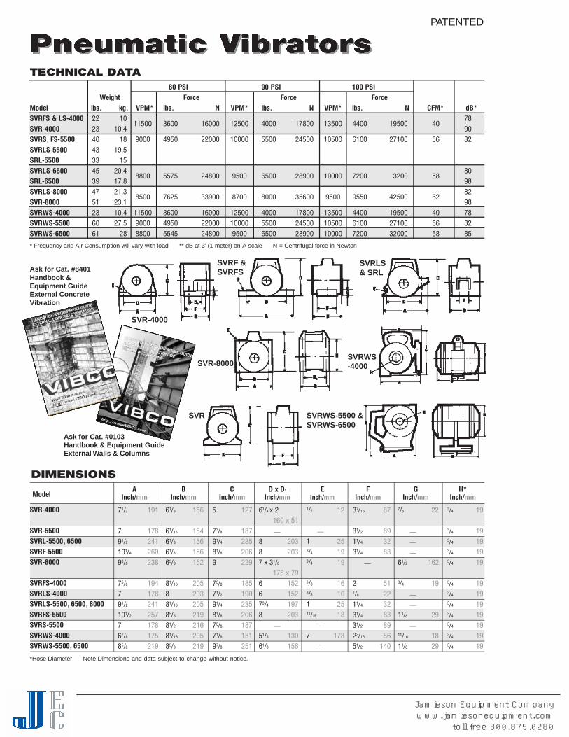
TECHNICAL DATA80 PSI 90 PSI 100 PSI
We i g h t F o rc e F o rc e F o rc eM o d e l l b s . k g . V P M * l b s . N V P M * l b s . N V P M * l b s . N C F M * d B *SVRFS & LS-4000 2 2 1 0 7 8
1 1 5 0 0 3 6 0 0 1 6 0 0 0 1 2 5 0 0 4 0 0 0 1 7 8 0 0 1 3 5 0 0 4 4 0 0 1 9 5 0 0 4 0S V R - 4 0 0 0 2 3 1 0 . 4 9 0SVRS, FS-5500 4 0 1 8 9 0 0 0 4 9 5 0 2 2 0 0 0 1 0 0 0 0 5 5 0 0 2 4 5 0 0 1 0 5 0 0 6 1 0 0 2 7 1 0 0 5 6 8 2S V R L S - 5 5 0 0 4 3 1 9 . 5S R L - 5 5 0 0 3 3 1 5S V R L S- 6 5 0 0 4 5 2 0 . 4 8 0
8 8 0 0 5 5 7 5 2 4 8 0 0 9 5 0 0 6 5 0 0 2 8 9 0 0 1 0 0 0 0 7 2 0 0 3 2 0 0 5 8S R L - 6 5 0 0 3 9 1 7 . 8 9 8S V R L S- 8 0 0 0 4 7 2 1 . 3 8 2
8 5 0 0 7 6 2 5 3 3 9 0 0 8 7 0 0 8 0 0 0 3 5 6 0 0 9 5 0 0 9 5 5 0 4 2 5 0 0 6 2S V R - 8 0 0 0 5 1 2 3 . 1 9 8S V RW S - 4 0 0 0 2 3 1 0 . 4 1 1 5 0 0 3 6 0 0 1 6 0 0 0 1 2 5 0 0 4 0 0 0 1 7 8 0 0 1 3 5 0 0 4 4 0 0 1 9 5 0 0 4 0 7 8S V RW S - 5 5 0 0 6 0 2 7 . 5 9 0 0 0 4 9 5 0 2 2 0 0 0 1 0 0 0 0 5 5 0 0 2 4 5 0 0 1 0 5 0 0 6 1 0 0 2 7 1 0 0 5 6 8 2S V RW S - 6 5 0 0 6 1 2 8 8 8 0 0 5 5 4 5 2 4 8 0 0 9 5 0 0 6 5 0 0 2 8 9 0 0 1 0 0 0 0 7 2 0 0 3 2 0 0 0 5 8 8 5
* Frequency and Air Consumption will va ry with load ** dB at 3' (1 meter) on A-scale N = Centrifugal force in New t o n
M o d e lD x D1
I n c h /m m
61/4 x 2
– —
887 x 31/8
6673/4
8– —
51/8
61/8
160 x 51
2 0 32 0 3
178 x 791 5 21 5 21 9 72 0 3
1 3 01 5 6
EI n c h /m m
1/2
– —
13/4
3/4
5/8
3/8
11 1/1 6
– —
7– —
1 2
2 51 91 9
1 61 02 51 8
1 7 8
FI n c h /m m
37/1 6
31/2
11/4
31/4
– —
27/8
11/4
31/4
31/2
23/1 6
51/2
8 7
8 93 28 3
5 12 23 28 38 95 6
1 4 0
AI n c h /m m
71/2
791/2
1 01/4
93/8
75/8
791/2
1 01/2
767/8
85/8
1 9 1
1 7 82 4 12 6 02 3 8
1 9 41 7 82 4 12 5 71 7 81 7 52 1 9
BI n c h /m m
61/8
61/1 6
61/8
61/8
63/8
81/1 6
881/1 6
85/8
81/2
81/1 6
85/8
1 5 6
1 5 41 5 61 5 61 6 2
2 0 52 0 32 0 52 1 92 1 62 0 52 1 9
CI n c h /m m
5
73/8
91/4
81/8
9
73/8
71/2
91/4
81/8
73/8
71/8
97/8
1 2 7
1 8 72 3 52 0 62 2 9
1 8 51 9 02 3 52 0 61 8 71 8 12 5 1
GI n c h /m m
7/8
– —
– —
– —
61/2
3/4
– —
– —
11/8
– —
1 1/1 6
11/8
2 2
1 6 2
1 9
2 9
1 82 9
DIMENSIONS
*Hose Diameter Note:Dimensions and data subject to change without notice.
H *I n c h /m m
3/4
3/4
3/4
3/4
3/4
3/4
3/4
3/4
3/4
3/4
3/4
3/4
1 9
1 91 91 91 9
1 91 91 91 91 91 91 9
S V R - 4 0 0 0
S V R - 5 5 0 0SVRL-5500, 6500S V R F - 5 5 0 0S V R - 8 0 0 0
S V R F S - 4 0 0 0S V R L S - 4 0 0 0SVRLS-5500, 6500, 8000S V R F S - 5 5 0 0S V R S - 5 5 0 0S V RW S - 4 0 0 0S V RWS-5500, 6500
PATENTED
SVR-4000
SVRF &SVRFS
SVRLS& SRL
SVR
SVR-8000SVRWS-4000
SVRWS-5500 &SVRWS-6500
Ask for Cat. #0103Handbook & Equipment GuideExternal Walls & Columns
Ask for Cat. #8401Handbook &Equipment GuideExternal ConcreteVibration
Jamieson Equipment Companywww.jamiesonequipment.com
toll free 800.875.0280

MODEL PF, HF, PC & HC“ B I G - B U S T E R ”PATENTED DESIGNSVIBCO has developed a new revo l u t i o n a ry vibration isolation dev i c eeliminating vibration tra n s fer from the vibrator part of the Big Buster to thed ri ve motor.
A vibration isolating coupling is mounted between the eccentric shaft andthe motor dri ve shaft eliminating any vibration tra n s fer through the shaft.Another vibration isolating coupling is connected between the vibra t o rhousing and the motor housing eliminating all vibration tra n s fe r.
GENERAL FEAT U R E SBig Buster vibrators provide high force at low frequency.T h ey aredesigned for continuous duty. All models are ava i l a ble in pneumatic or hy d raulic dri ve. Big Buster units are designed with sealed beari n g s.A i rline lubrication is required for the air motor va n e s.
A D VA N TA G E SWith this unique design, premature failure of the dri ve unit is eliminated, and the full life can be expected of the dri ve unit, which will drastically addto the unit life and eliminate costly shutdowns and maintenance costs. T h eunit can now truly be used continuously and economically which is the BIG advantage over competitive units.
WHERE TO USE?These units are ideal for the toughest applications from unloading railroad cars to moving materials in huge bins and hoppers (capacity over 150,000 lbs.) Precise speed control allows “ t u n i n g ” of the vibra t o rfor best results in any application. Big Busters are ava i l a ble in clamp onbase for portability and bolt-on base for permanent mounting.
PATENTED DESIGNSGENERAL FEAT U R E SV I B C O ’s hy d raulic vibrators operate in any position and are not a f fected by dirt y, muddy or wet locations. T h ey can operate on pressures up to 3000 PSI making them ideal to use with constru c t i o nand fo rm equipment for a va riety of applications.
MODEL LHV I B C O ’s new patented LH-series of heavy duty hy d raulic vibrators have beendesigned to eliminate the constant failures and short life associated withhy d raulic vibrators using a hy d raulic motor with needle beari n g s. Use of largeroller & ball bearings provide these vibrators with a longer, troubl e - f r e e,s e rvice life. The LH-series offers a compact design and can handle pressuresup to 3000 PSI. The LH vibrators produce a linear force that makes the unitideal for fe e d e r s, packing tables as well as moving material in bins & hoppers,as a dump tru ck body vibra t o r, or consolidating concrete or asphalt. LHS unitswith space saver design and sinusodial rotary fo r c e, ideal for bins & hoppers.
MODEL HLFThe small version of the Big Buster HF-Units are equipped with an i n t e rnal coupling to minimize the wear of the hy d raulic motor. These smalland powerful high speed 9000 RPM vibrators offer an inex p e n s i ve solution to many material handling probl e m s. HL 3000 same design asthe HF-Fit LC-1 Lug Bra cke t . Creates 3000 lbs. force at 7000 RPM - ideal for concrete applications.
MODEL BH y d raulic fluid under pressure dri ves a specially designed and patented turbine wheel producing high frequency vibration with noisel evels as low as 60-62 dB at maximum speed. A real low cost unit idealfor 0.E.M equipment.
LHS-1800LHS-2500
LH-3500LH-5000
LH-1000LH-2000
PNEUMATIC &HYDRAULIC VIBRATORS
HLF-1300
HLF-700
PF-3500(HF-3500)
PC-3500HC-3500
HL-3000
B-190 B-250 B-320
Jamieson Equipment Companywww.jamiesonequipment.com
toll free 800.875.0280

• AIR & HYDRAULIC DRIVE• FORCES TO 3500 LBS.• SPEEDS TO 5600 VPM
TECHNICAL DATA60 PSI
Pneumatic Weight Speed Force Hydraulic Weight Avg. Speed GPM ForceModels lbs. kg. VPM SCFM lbs N Models lbs. kg. PSI VPM ( max.) lbs. N dB*PF-800 60 27 4000 11 800 3559 HF-800 60 27 600 5000 3.2 1300 5784 72PF-1200 60 27 3500 21 1200 5338 HF-1200 60 27 800 4500 2.9 1900 8452 74PF-1500 60 27 3500 31 1500 6672 HF-1500 60 27 900 4000 2.6 2000 8898 76PF-PC-3500 72 33 3500 39 3500 15572 HF-HC-3500 72 33 1200 3500 2.4 3500 15572 80
HL-3000 39 17.7 1000 5000 3.2 3400 15124 76HLF-700 14 6.5 900 9000 2.8 700 3114 72HLF-1300 20 9 1000 9000 2.8 1300 5784 72
600 PSI 800 PSI 1000 PSIWeight Force Force Force
Model lbs. kg. VPM GPM lbs N VPM GPM lbs N VPM GPM lbs NB-190 1 .453 4600 4.5 189 891 6100 4.8 332 77 7400 6.5 488 221B-250 2 .907 4200 4.5 280 1246 5000 4.5 397 1766 5800 6.5 534 242B-320 31/2 1.6 3700 5.0 301 1339 4500 6.0 445 1980 5300 7.0 617 280
*Decibels at 3’(1 meter) on A-scaleN = Centrifugal force in Newton
Frequency will vary with load.
***Maximum pressure 3000 PSI.
N = Centrifugal force in New t o n . M a x i mum pressure 3000 PSI. Frequency will va ry with load.
2.5 Gal. 3 Gal. 4 Gal.Force Force Force Weight
Model VPM PSI lbs. VPM PSI lbs. VPM PSI lbs. lbs / kg. dBLH-1000* 2500 350 270 3600 400 600 4700 600 1000 30 13.6 72LH-3500* 4000 500 2100 4600 600 2800 5300 850 3500 62 28 76LHS-1500* 3200 500 700 4500 600 1500 5300 750 1800 40 18 74Average figures, subject to change without notice. * LH-1000, LH-3500, LHS-1500 Standard Sizes LH-2000, 2000 lbs. at 4600 VPM, LH-5000, 5000 lbs. at 5300 VPM,LHS-2500, 2500 lbs. at 5000 VPM. Frequency will va ry with load.
• Q U I E T• CONTINUOUS DUTY
DIMENSIONS:A B C D E F* G H I J K
Model Inch / mm Inch / mm Inch / mm Inch / mm Inch / mm Inch / mm Inch / mm Inch / mm Inch / mm Inch / mm Inch / mmB-190 51/4 133 11/1 6 27 45/8 117 4 102 1 3/1 6 21 21/8 54 15/1 6 33 3/8 10 3/8 - NPT 3/8 - NPT 31/4 83B-250 7 178 11/4 32 53/8 137 5 127 1 25 31/2 89 21/4 57 1/2 13 1/2 - NPT 1/2 - NPT 33/8 86B-320 67/8 117 11 1/1 6 43 57/8 149 5 127 11/1 6 27 33/4 95 25/8 67 1/2 13 1/2 - NPT 1/2 - NPT 35/8 92PF-HF-800,1200, 1500 103/8 265 83/4 222 111/4 286 81/2 216 3/4 - 16SAE 3/4 19 – 3 76 – – –PF-HF-3500 103/4 273 91/4 235 125/8 321 81/2 216 3/4 - 16SAE 5/8 16 21/2 64 41/4 108 – – –PC-HC-3500 121/2 318 103/4 273 121/4 311 101/1 6 256 3/4 - 16SAE 11/4 12NF – 13/1 6 30 – – –HLF-700 5 127 41/2 114 7 178 31/2 89 9/1 6 - 18SAE 1/2 13 – – – – –HLF-1300 53/4 146 51/8 130 75/8 194 41/2 114 9/1 6 - 18SAE 1/2 13 – – – – –HL-3000 83/4 222 83/4 222 111/4 286 73/4 197 3/4 - 16SAE 1 25 – 11/1 6 27 – – –
G D F A C B EModel Inch / mm Inch / mm Inch / mm Inch / mm Inch / mm Inch / mm Inch / mmLH-1000 3 76 41/2 114 1/2 12 51/2 140 81/2 216 43/4 121 3/8 - NPTLH-2000 3 76 41/2 114 1/2 12 51/2 140 101/2 267 43/4 121 3/8 - NPTLH-3500 3 76 81/2 216 3/4 19 101/4 260 113/8 289 61/8 156 3/8 - NPTLH-5000 3 76 81/2 216 3/4 19 101/4 260 133/8 340 61/8 156 3/8 - NPTLHS-1500 81/2 216 3/4 19 101/4 260 91/4 235 61/8 156 3/8 - NPTLHS-2500 81/2 216 3/4 19 101/4 260 101/4 260 61/8 156 3/8 - NPT
• A D J U S TABLE SPEED• FOOT & CLAMP
M O U N T
*Bolt Size ** dB at 3' (1 meter) on A-scale N = Centrifugal force in New t o nNote:Dimensions and data subject to change without notice.
B-MODELS
HL PC-HCPF-HF
HLF
LHSLH
LH & LHS
PATENTED
Jamieson Equipment Companywww.jamiesonequipment.com
toll free 800.875.0280

TECHNICAL DATA
M o d e l A m p .
2 . 52 . 51 . 32 . 61 . 73 . 01 . 72 . 03 . 56 . 5
* * * Vo l t P h . Cont. Duty Int. DutyVibrations per Minute W t .
l b s . N
2 2 32 6 74 4 58 9 0
1 3 3 51 5 5 81 7 8 01 7 8 02 2 2 54 4 4 9
l b s .
85 and 8**1 11 21 62 01 21 64 35 8
d B *
7 16 86 87 07 07 17 07 07 07 2
k g .
F o rce (Impact) lbs./NA d j u s t a b l e
5 06 01 0 02 0 03 0 03 5 04 0 04 0 05 0 01 0 0 0
1111111111
9 5 0 - 2 5 0 09 5 0 - 2 5 0 09 5 0 - 2 5 0 09 5 0 - 2 5 0 09 5 0 - 2 5 0 09 5 0 - 2 5 0 09 5 0 - 2 5 0 09 5 0 - 2 5 0 09 5 0 - 2 5 0 09 5 0 - 2 5 0 0
2 5 0 0 - 4 0 0 02 5 0 0 - 4 0 0 02 5 0 0 - 4 0 0 02 5 0 0 - 4 0 0 02 5 0 0 - 4 0 0 02 5 0 0 - 4 0 0 02 5 0 0 - 4 0 0 02 5 0 0 - 4 0 0 02 5 0 0 - 4 0 0 02 5 0 0 - 4 0 0 0
1 1 5 / 2 3 01 1 5 / 2 3 01 1 5 / 2 3 01 1 5 / 2 3 01 1 5 / 2 3 01 1 5 / 2 3 01 1 5 / 2 3 01 1 5 / 2 3 01 1 5 / 2 3 01 1 5 / 2 3 0
3 . 62 . 3 / 3 . 6
5 . 05 . 47 . 39 . 15 . 57 . 3
1 9 . 52 6 . 0
SCR-100 on Filling Station SCR-300 keeps material flowing evenly to belt conveyor
Another first by VIBCO – A n o i s e l e s s, heavy duty electric vibrator thatcan be force and speed a d j u s t e d while ru n n i n g .U n l i ke old-fa s h i o n e d ,noisy electro-magnetic vibra t o r s, this newly developed silent motorv i b rator can meet even the most stringent anti-noise pollutionr e q u i r e m e n t .
Model SCR consists of a rugged, permanent magnet DC motor, andSCR control, which is composed of a solid state, full wave rectifier and
MODEL SCRAdjustable Speed & ForceFEATURES:• 0-4000 RPM • ADJUSTABLE FORCE• TOTALLY ENCLOSED, SILENT• HEAVY, CONTINUOUS DUTY• 115-VOLT PLUG-IN• EASY SPEED DIAL CONTROL
standard 115-volt AC current.No special wiring or circuitry is needed.Accurate and reliable performances throughout the full speed range.Totally enclosed, non-vented housing makes the SCR ideal for useinside or outside in dusty or wet locations. Easy to adjust eccentricsettings give additional adjustability. SCR is continuous duty rated evenat maximum eccentric setting.
WHERE TO USE:BINS, CHUTES: Controlled feed.Dial control vibration gives positiveflow rate from trickle to torrent, even with hard to move materials ordifferent bin contents.
PACKAGING: Select and settle. Select ideal shake for optimumdensification and settling.
SCREENING: Fast, non-blinding. For sifting, scalping and sorting,controlled vibration gives fastest and most complete results.
TEST TABLES: Verify part integrity, simulate handling and over theroad transport.Low cost, full range control gives multitude of speeds,“G” values and amplitudes necessary to meet most specs.
*Decibel at 3' (1 meter on A-Scale) N = Centrifugal force in Newton **5 lbs. Aluminum 8 lbs. Cast Iron ***50 or 60Hz ‡WatertightNote:Dimensions and data subject to change without notice.
SCR-50
SCR-60
SCR-100
SCR-200
SCR-300
S C R - 5 0S C R - 6 0 ‡S C R - 1 0 0S C R - 2 0 0S C R - 3 0 0S C R - 3 5 0S C RW- 4 0 0 ‡S C R - 4 0 0S C R - 5 0 0S C R - 1 0 0 0
SCR-350
Jamieson Equipment Companywww.jamiesonequipment.com
toll free 800.875.0280

DIMENSIONS
M o d e l
*Bolt size to be used Note:Dimensions and data subject to change without notice.
Linch / m m
Winch / m m
Hinch / m m
Ainch / m m
Binch / m m
C *inch / m m
Dinch / m m
Einch / m m
SCR-50, SCR-100 SCR-200, SCR-350 SCR-300, 400, 500 & 1000
57/8
63/8
63/4
83/1 6
81/2
81/4
991 33/1 6
1 41/4
1 4 91 6 21 8 72 0 82 1 62 1 02 2 92 2 93 3 53 6 2
541/2
647/8
41/8
55/8
61/4
41/8
53/4
61/2
1 2 71 1 41 5 21 2 41 0 51 4 31 5 91 0 51 4 61 6 5
35/8
31/4
41/4
41/8
551/4
53/8
561/2
71/2
6 48 3
1 0 81 0 51 2 71 3 31 3 71 2 71 6 51 9 0
435/8
531/2
341/2
51/4
341/2
5
1 0 26 4
1 2 78 97 6
1 1 41 3 37 6
1 1 41 2 7
—15/1 6
——
53/4
—41/4
53/4
81 5/1 6
93/8
3 3
1 4 5
1 1 41 4 52 2 72 3 8
3/8
5/1 6
3/8
1/2
5/1 6
1/2
7/1 6
5/1 6
1/2
5/8
1 08
1 01 28
1 21 48
1 21 6
334439/1 6
51/1 6
39/1 6
51/1 6
6
7 67 6
1 0 21 0 29 0
1 2 8
9 01 2 81 4 0
35/1 6
—
61/2
61/2
—
61/2
——
1 0 0
1 6 51 6 5
1 6 5
SCRW-400
SCR-400
SCR-300 on PC-Board FrameSCR-500 on Box Dumper to prevent hang-ups.
SCR-60, SCRW-400
Ask for Cat. #0104Electric VibratorsAdjustable Speed & Force
S C R - 5 0S C R - 6 0S C R - 1 0 0S C R - 2 0 0S C R - 3 0 0S C R - 3 5 0S C RW- 4 0 0S C R - 4 0 0S C R - 5 0 0S C R - 1 0 0 0
• Controlstandard onall units
SCR-1000SCR-500
Jamieson Equipment Companywww.jamiesonequipment.com
toll free 800.875.0280

Vertically mounted 2P-450 on CrushedCullet Hopper.
4P-700 on Woodchip Bin with Screw Feeder.
2P-200 on Dust Collector Hoppers.
V I B C O noiseless motor vibrators made in the U. S. by skilledA m e rican craftsmen fo l l ow American NEMA and ASTMEs t a n d a r d s. V I B C OV i b rators are totally enclosed, continuous dutyand completely noiseless. T h ey can be used inside or outside, indust, dirt, rain or snow. V I B C O’s lines of heavy duty vibrators wills o l ve any vibration problem such as: speed the flow of bu l km a t e rials through the smallest bin, hopper, and chute, to thelargest silo; p a ck materials in drums and bags; c o n s o l i d a t econcrete in pipe, precast and prestressed industri e s ; for screensand screeds and a va riety of other industrial applications.
2P Models with 3600 rpm are the most versatile and popularv i b ra t o r s. C e n t rifugal force output from 50-5600 Ibs. used on alltypes of bins containing fine to gra nular materi a l s, for pack i n gcoarse materials and casting concrete, etc.
4P Models with 1800 rpm have a force output of 100 to 15,000I b s. Used on bins containing lumpy or sticky materials for pack i n glight fluffy materi a l s, also a typical screen vibra t o r.
6P and 8P Models with 1200 and 900 rpm are used inapplications requiring low frequency and ve ry high amplitudev i b ration such as screening and packing of ve ry light and fluffy materi a l s.
WHY VIBCO?? BECAUSE . . . . .CHOICE: 31 models all made in the U.S.A. Heavy duty andcompletely self-contained units.DURABILITY: Built stronger throughout; years of service in all types of applications, inside and outside, have proven theVIBCO quality.EFFECTIVE: Multi-directional force proven safest to yourequipment and most efficient.NOISELESS: No more sound than an electric motor.ECONOMY: Maintenance free, no costly controls, lowoperating cost.GUARANTEE: Every VIBCO Vibrator is fully guaranteed bothmechanically and performance-wise.
SERVICE: Over forty years of vibration know-how, anddistributors throughout the U.S.A.
DESIGN: • Adjustable eccentrics for easy change offorce to suit application.
• Load equally distributed over bearings foradditional life.
• Unloaded rotor on the larger units to preventburnout from rotor hitting stator lamination.
• Oversized electric motor for higher safetyfactor - watt/lbs. impact.
• High heat resistant winding to take additionaloverload and heat.
• Oversized bearings for longer life.
• Mounting bolts over force center for efficientvibration transfer.
• Terminal box for easy connection and changeof voltage.
• Internal vent holes for better air circulationcooling in high temperature application.
• T O TA L LY ENCLOSED
• FOR INDOOR OR OUTDOOR USE
• C O M P L E T E LY NOISELESS
• A D J U S TABLE ECCENTRICS
• SINGLE & 3 PHASE
2P-752P-150
2P-4504P-7006P-300
2P-2002P-350
2P-100
Jamieson Equipment Companywww.jamiesonequipment.com
toll free 800.875.0280

*Bolt Size +Use Figure 2 for dimensions Note:Dimensions and data subject to change without notice.
M o d e l P h a s e
1 & 3
1 & 3
1 & 3
1 & 3
1 & 3
1
3
1
3
1 & 3
1 & 3
1
3
3
1 & 3
3
3
3
3
3
3
3
LI n c h /m m
77/8
83/16
103/4
111/2
13
131/2
12 3/8
12 3/8
111/4
131/8
151/2
151/4
143/8
161/2
171/2
18 1/2
22 1/4
18
221/2
24
293/4
200
208
273
292
330
343
314
314
286
333
394
387
365
419
445
470
565
457
572
610
756
WI n c h /m m
41/8
41/8
47/8
53/4
53/4
61/2
61/2
61/2
61/2
61/2
61/2
71/2
71/2
71/2
71/2
71/2
101/4
71/4
101/4
101/4
155/8
105
105
124
146
146
165
165
165
165
165
165
191
191
191
191
191
260
184
260
260
397
HI n c h /m m
5
5
61/4
63/4
63/4
71/2
71/2
71/2
71/2
71/2
75/8
81/2
81/2
81/2
81/2
81/2
101/2
81/2
101/2
101/2
13
127
127
159
171
171
191
191
191
191
191
194
216
216
216
216
216
267
216
267
267
330
AI n c h /m m
3
3
31/2
41/2
41/2
5
5
5
5
5
5
51/2
51/2
51/2
51/2
51/2
77/8
51/2
77/8
77/8
125/8
76
76
89
114
114
127
127
127
127
127
127
140
140
140
140
140
200
140
200
200
321
BI n c h /m m
411/16
413/16
63/8
7
77/8
83/8
(75/8)
(75/8)
(67/8)
(83/8)
83/8
95/8
85/8
1013/16
115/8
115/8
1213/16
1013/16
123/4
1213/16
151/2
119
122
162
178
200
213
194
194
175
213
213
244
219
259
295
295
325
275
324
325
394
C *I n c h /m m
5/16
5/16
1/2
1/2
1/2
5/8
5/8
5/8
5/8
5/8
5/8
5/8
5/8
5/8
5/8
5/8
1
1
1
1
11/4
8
8
13
13
13
16
16
16
16
16
16
16
16
16
16
16
25
25
25
25
32
DI n c h /m m
39/16
39/16
4
5
5
6
6
6
6
6
6
7
7
7
7
7
87/8
7
87/8
87/8
103/4
90
90
102
127
127
152
152
152
152
152
152
178
178
178
178
178
225
178
225
225
273
DIMENSIONSE
I n c h /m m
41/8
41/8
41/4
5
5
6
6
6
6
6
6
7
7
7
7
7
87/8
7
87/8
87/8
2
105
105
108
127
127
152
152
152
152
152
152
178
178
178
178
178
225
178
225
225
51
2P-75
2P-100
2P-150
2P-200
4P-350
4P-600
2P-450
2PS-450
4P-700
4P-1000
6P-500
2P-800
2P-1700
4P-1400
2P-2500
2P-3500
2P-4500
2P-5500
4P-2000
6P-1000
8P-500
4P-3000
6P-1500
8P-750
4P-5000
6P-2500
8P-1250
4P-10000 +
6P-5000 +
8P-2500 +
4P-1000,6P-500
2P-800, 2P-1700,2P-2500, 2P-3500
4P-2000, 4P-50006P-1000, 8P-500
4P-10000
Jamieson Equipment Companywww.jamiesonequipment.com
toll free 800.875.0280
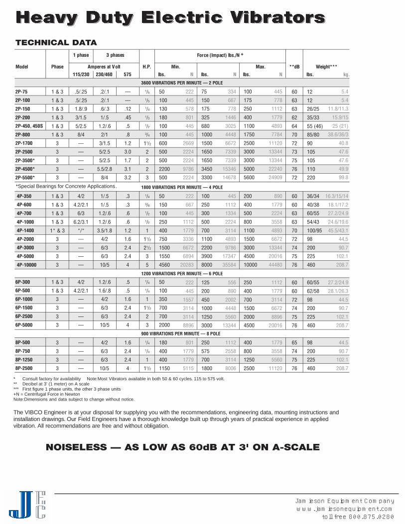
NOISELESS — AS LOW AS 60dB AT 3' ON A-SCALE
* Consult factory for availability Note:Most Vibrators available in both 50 & 60 cycles. 115 to 575 volt.** Decibel at 3' (1 meter) on A scale*** First figure 1 phase units, the other 3 phase units+N = Centrifugal Force in NewtonNote:Dimensions and data subject to change without notice.
The VIBCO Engineer is at your disposal for supplying you with the recommendations, engineering data, mounting instructions andinstallation draw i n g s. Our Field Engineers have a thorough knowledge built up through years of practical ex p e rience in appliedv i b ra t i o n . All recommendations are free and without obl i g a t i o n .
TECHNICAL DATA
2 P - 7 5
2 P - 1 0 0
2 P - 1 5 0
2 P - 2 0 0
2P-450, 450S
2 P - 8 0 0
2 P - 1 7 0 0
2 P - 2 5 0 0
2 P - 3 5 0 0 *
2 P - 4 5 0 0 *
2 P - 5 5 0 0 *
1 & 3
1 & 3
1 & 3
1 & 3
1 & 3
1 & 3
3
3
3
3
3
. 5 / . 2 5
. 5 / . 2 5
1 . 8 / . 9
3 / 1 . 5
5 / 2 . 5
8 / 4
—
—
—
—
—
. 2 / . 1
. 2 / . 1
. 6 / . 3
1 / . 5
1 . 2 / . 6
2 / 1
3 / 1 . 5
5 / 2 . 5
5 / 2 . 5
5 . 5 / 2 . 8
8 / 4
—
—
. 1 2
. 4 5
. 5
. 8
1 . 2
3 . 0
1 . 7
3 . 1
3 . 2
5 0
1 0 0
1 3 0
1 8 0
1 0 0
1 0 0
6 0 0
5 0 0
5 0 0
2 2 0 0
5 0 0
2 2 2
4 4 5
5 7 8
8 0 1
4 4 5
4 4 5
2 6 6 9
2 2 2 4
2 2 2 4
9 7 8 6
2 2 2 4
7 5
1 5 0
1 7 5
3 2 5
6 8 0
1 0 0 0
1 5 0 0
1 6 5 0
1 6 5 0
3 4 5 0
3 3 0 0
3 3 4
6 6 7
7 7 8
1 4 4 6
3 0 2 5
4 4 4 8
6 6 7 2
7 3 3 9
7 3 3 9
1 5 3 4 6
1 4 6 7 8
1 0 0
1 7 5
2 5 0
4 0 0
1 1 0 0
1 7 5 0
2 5 0 0
3 0 0 0
3 0 0 0
5 0 0 0
5 6 0 0
4 4 5
7 7 8
1 1 1 2
1 7 7 9
4 8 9 3
7 7 8 4
1 1 1 2 0
1 3 3 4 4
1 3 3 4 4
2 2 2 4 0
2 4 9 0 9
5 . 4
5 . 4
1 1 . 8 / 1 1 . 3
1 5 . 9 / 1 5
25 (21)
3 8 . 6 / 3 6 / 3
4 0 . 8
4 7 . 6
4 7 . 6
4 9 . 9
9 9 . 8
1/5
1/5
1/4
1/3
1/2
3/4
11/2
2
2
2
3
M o d e l P h a s e
1 phase
3600 VIBRATIONS PER MINUTE — 2 POLE
3 phases F o rce (Impact) lbs./N +
A m p e res at Vo l t H . P. * * d B
1 1 5 / 2 3 0 2 3 0 / 4 6 0 5 7 5
M i n .
l b s . N
M a x .
l b s . Nl b s . N
We i g h t * * *
l b s . k g .
6 0
6 3
6 3
6 2
6 4
7 0
7 2
7 3
7 5
7 6
7 2
4 P - 3 5 0
4 P - 6 0 0
4 P - 7 0 0
4 P - 1 0 0 0
4 P - 1 4 0 0
4 P - 2 0 0 0
4 P - 3 0 0 0
4 P - 5 0 0 0
4 P - 1 0 0 0 0
1 & 3
1 & 3
1 & 3
1 & 3
1* & 3
3
3
3
3
4 / 2
4 . 2 / 2 . 1
6 / 3
6 . 2 / 3 . 1
* / *
—
—
—
—
1 / . 5
1 / . 5
1 . 2 / . 6
1 . 2 / . 6
3 . 5 / 1 . 8
4 / 2
6 / 3
6 / 3
1 0 / 5
. 3
. 3
. 6
. 6
1 . 2
1 . 6
2 . 4
2 . 4
4
5 0
1 5 0
1 0 0
2 5 0
4 0 0
7 5 0
1 5 0 0
1 5 5 0
4 5 6 0
2 2 2
6 6 7
4 4 5
1 1 1 2
1 7 7 9
3 3 3 6
6 6 7 2
6 8 9 4
2 0 2 8 3
1 0 0
2 5 0
3 0 0
5 0 0
7 0 0
1 1 0 0
2 2 0 0
3 9 0 0
8 0 0 0
2 0 0
4 0 0
5 0 0
8 0 0
1 1 0 0
1 5 0 0
3 0 0 0
4 5 0 0
1 0 0 0 0
8 9 0
1 7 7 9
2 2 2 4
3 5 5 8
4 8 9 3
6 6 7 2
1 3 3 4 4
2 0 0 1 6
4 4 4 8 0
1/4
3/8
1/2
1/2
1
11/2
21/2
3
5
1800 VIBRATIONS PER MINUTE — 4 POLE
6 0
6 0
6 3
6 3
7 0
7 2
7 4
7 5
7 6
6 P - 3 0 0
6 P - 5 0 0
6 P - 1 0 0 0
6 P - 1 5 0 0
6 P - 2 5 0 0
6 P - 5 0 0 0
1 & 3
1 & 3
3
3
3
3
4 / 2
4 . 2 / 2 . 1
—
—
—
—
1 . 2 / . 6
1 . 6 / . 8
4 / 2
6 / 3
6 / 3
1 0 / 5
. 5
. 5
1 . 6
2 . 4
2 . 4
4
5 0
1 0 0
3 5 0
7 0 0
7 0 0
2 0 0 0
2 2 2
4 4 5
1 5 5 7
3 1 1 4
3 1 1 4
8 8 9 6
1 2 5
2 0 0
4 5 0
1 0 0 0
1 2 5 0
3 0 0 0
5 5 6
8 9 0
2 0 0 2
4 4 4 8
5 5 6 0
1 3 3 4 4
2 5 0
4 0 0
7 0 0
1 5 0 0
2 0 0 0
4 5 0 0
1 1 1 2
1 7 7 9
3 1 1 4
6 6 7 2
8 8 9 6
2 0 0 1 6
1/4
1/4
1
11/2
2
3
1200 VIBRATIONS PER MINUTE — 6 POLE
6 0
6 0
7 2
7 4
7 5
7 6
8 P - 5 0 0
8 P - 7 5 0
8 P - 1 2 5 0
8 P - 2 5 0 0
3
3
3
3
—
—
—
—
4 / 2
6 / 3
6 / 3
1 0 / 5
1 . 6
2 . 4
2 . 4
4
1 8 0
4 0 0
4 0 0
1 1 5 0
8 0 1
1 7 7 9
1 7 7 9
5 1 1 5
2 5 0
5 7 5
7 0 0
1 8 0 0
1 1 1 2
2 5 5 8
3 1 1 4
8 0 0 6
4 0 0
8 0 0
1 2 5 0
2 5 0 0
1 7 7 9
3 5 5 8
5 5 6 0
1 1 1 2 0
9 8
2 0 0
2 2 5
4 6 0
4 4 . 5
9 0 . 7
1 0 2 . 1
2 0 8 . 7
1/4
1/4
1
11/2
900 VIBRATIONS PER MINUTE — 8 POLE
6 5
7 4
7 5
7 6
*Special Bearings for Concrete Applications.
1 2
1 2
2 6 / 2 5
3 5 / 3 3
55 (46)
8 5 / 8 0
9 0
1 0 5
1 0 5
1 1 0
2 2 0
4 4 5
1 1 1 2
1 3 3 4
2 2 2 4
3 1 1 4
4 8 9 3
9 7 8 6
1 7 3 4 7
3 5 5 8 4
3 6 / 3 4
4 0 / 3 8
6 0 / 5 5
5 4 / 4 3
1 0 0 / 9 5
9 8
2 0 0
2 2 5
4 6 0
1 6 . 3 / 1 5 / 1 4
1 8 . 1 / 1 7 . 2
2 7 . 2 / 2 4 . 9
2 4 . 6 / 1 9 . 6
4 5 . 5 / 4 3 . 1
4 4 . 5
9 0 . 7
1 0 2 . 1
2 0 8 . 7
6 0 / 5 5
6 2 / 5 8
9 8
2 0 0
2 2 5
4 6 0
2 7 . 2 / 2 4 . 9
2 8 . 1 / 2 6 . 3
4 4 . 5
9 0 . 7
1 0 2 . 1
2 0 8 . 7
Jamieson Equipment Companywww.jamiesonequipment.com
toll free 800.875.0280

Model 2P-4500 on pipe form
Model 2P-1700 on gypsum board
Two Model 4P-5000’s on feeder
Model 2P-150 on hopper feeding conveyor belt
Model 2P-3500 on multiple chemical bins
Model 2P-200 on transfer bin
Two Model 4P-3000’s on gaylordpacking table
Two Model 2P-800’s feedingscrew conveyor
Jamieson Equipment Companywww.jamiesonequipment.com
toll free 800.875.0280

MODEL SPRSmall Impact Line
F E AT U R E S :
• C O M PA C T
• N O I S E L E S S
• CONTINUOUS DUTY
• L I G H T W E I G H T
• STOPS & STA RT SE A S I LY
• CONVENIENT -115 VOLT PLUG IN
SPR-20 and -21 SPRT-21 SPWT-21, SPWT-60 and -80
M o d e l
F o rc eI m p a c t
lbs. N
Adjust-able
SpeedOption
C E - 6 0 * * *
S P R - 2 0
S P R - 2 1
S P R - 4 0
S P R - 6 0 & 6 0 H D
S P R - 8 0 & 8 0 H D
S P RT- 2 1
S P RT- 6 0 & 6 0 H D
S P RT- 8 0 & 8 0 H D
S P W T- 2 1
S P W T- 6 0
S P W T- 8 0
1 0 0
1 5
2 0
2 5
6 0
8 0
2 0
6 0
8 0
2 0
6 0
8 0
‡ Vo l t
1 1 5
1 1 5
1 1 5
1 1 5
1 1 5
1 1 5
1 1 5
1 1 5
1 1 5
1 1 5
1 1 5
1 1 5
A m p s
. 3
. 5
. 8
1 . 4
1 . 5
1 . 7
1 . 4
1 . 5
1 . 7
1 . 4
1 . 5
1 . 7
P h .
1
1
1
1
1
1
1
1
1
1
1
1
Ye s
Ye s
Ye s
Ye s
P a rt l y
P a rt l y
Ye s
P a rt l y
P a rt l y
Ye s
P a rt l y
P a rt l y
E n c l o s u re d B *S p e e dV. P. M .
3 6 0 0
1 6 0 0
3 2 0 0
1 6 0 0
3 2 0 0
3 2 0 0
3 2 0 0
3 2 0 0
3 2 0 0
3 2 0 0
3 2 0 0
3 2 0 0
W t .lbs. k g .
6 5
4 5
4 8
4 5
4 8
5 0
4 5
4 8
5 0
4 5
4 8
5 0
8 * *
3
3
7
7
7
3
7
7
7
7
7
3 . 6
1 . 4
1 . 4
3 . 2
3 . 2
3 . 2
1 . 4
3 . 2
3 . 2
3 . 2
3 . 2
3 . 2
4 4 5
6 7
8 9
1 1 1
2 6 7
3 5 6
8 9
2 6 7
3 5 6
8 9
2 6 7
3 5 6
TECHNICAL DATA
Wa t e rt i g h t
O p e n
O p e n
Tot. Encl.& FanC o o l e d
Tot. Encl.
Tot. Encl.
Tot. Encl.
Wa t e rt i g h t
Wa t e rt i g h t
Wa t e rt i g h t
N = Centrifugal force in Newton **5 lbs. Aluminum *dB at 3’(1 meter) on A scale ***CE in aluminum or cast iron housings ‡Most units also available in 230 volt.Note:Dimensions and data subject to change without notice.
VlBCO’s Model SPR, SPRT, SPWT and CE electric motor vibrators are specially developed for the thousands of applicationswhere only a small shake is necessary, but big vibrator reliability is a must. For activating small hoppers, screens, chutes, tables,filling machines, etc. Controlled flow is obtained on all types of materials, including fine powders, flakes, pills, bottle caps andjars, etc. Speed and force can be adjusted on most models with simple rheostats or speed adjusters.
Completely noiseless operation (no more sound than a fan motor) makes these vibrators desirable in applications where noise isirritating or fatiguing for the employee. Most units available in 230 volt 50 or 60 cycles.
Rugged construction permits continuous or repeated start and stop operation in any position.
SPR-60HD, 80HD and SPRT-60HD, 80HD and CE are heavy duty units with oversized bearing and cast iron end bell instead ofaluminum for extra long life.
SPR-60HD lining sheet paper in print shop.
SPR-80 on circuit board plating tank. SPR-60 preventing hangups in hopperwith pasta feeding weigh belt feeder.
Jamieson Equipment Companywww.jamiesonequipment.com
toll free 800.875.0280

DIMENSIONS
M o d e l
C E - 6 0
SPR-20, 21, SPRT- 2 1
SPR-40, 60, 80 & HD
S P RT-60, 80 & HD
S P W T-21, 60, 80
61/1 6
5
7
51/2
53/8
1 5 4
1 2 7
1 7 8
1 4 0
1 3 7
Linch / m m
43/8
5
6
6
51/2
1 1 1
1 2 7
1 5 2
1 5 2
1 4 0
Winch / m m
31/4
31/2
41/4
41/4
61/2
8 3
8 9
1 0 8
1 0 8
1 6 5
Hinch / m m
35/8
4
5
5
43/4
9 2
1 0 2
1 2 7
1 2 7
1 2 1
Ainch / m m
1/4
3/8
3/8
3/8
3/8
6
1 0
1 0
1 0
1 0
C *inch / m m
3
31/2
4
43/1 6
41/2
7 6
8 9
1 0 2
1 0 6
1 1 4
Dinch / m m
7/1 6
7/1 6
1/2
1/2
5/8
1 1
1 1
1 3
1 3
1 6
Einch / m m
15/1 6
—
—
—
23/4
3 3
7 0
Binch / m m
SPWT
SPR-20 prevents plastic bottles froma c c u mulating and sticking on conveyor belt.
SPR-60 on filling machine. SPWT-80 on screen feeder.
—
4
57/8
41/2
—
1 0 2
1 4 9
1 1 4
Finch / m m
*Bolt Size Note:Dimensions & data subject to change without notice.
SPR-40, -60, -80 SPRT-60 and -80 CE-60SPR-60HD and 80HD
CESPR & SPRT
Jamieson Equipment Companywww.jamiesonequipment.com
toll free 800.875.0280

MODEL USF E ATURES: • HIGH SPEED • R U G G E D• SPEED ADJUSTABLE • 115 VOLT PLUG IN
US-450DC-450
DC-300
TECHNICAL DATA
Casting Concrete.Model US is idealboth at the precastplant on tables, vaults,septic tanks, patioblocks, steps, etc., andat the construction sitegiving “architectural”finishes and fireproofing to poured-in-place walls and columns.Ask for Catalog 0103.Model US-900, the most popular unit for septictanks, burial vaults, step forms, for architectural surface finish and fireproofing columns, casting tables for up to 300 Ibs. of product. US-1600the problem solver - for similar applications as the US-900. See page35 and 36 for different brackets. Ask for Catalog 8401.
Bins & Weigh-Batchers. The US-450 has become the standard unitthroughout the industry for weigh-batchers. The US-700, US-900 andUS-1600 for moving powdery and sticky materials in bins and chutes.
Fatigue and Test Tables. For verifying integrity of electric circuits,removing dangerous residues, detect marginal connections.
DC-60
V l B C O ’s Model US High Frequency line are 115 volt single phase motorswith low amperage draw. T h ey can be plugged into any light outlet oro p e rated from field genera t o r s. All units are speed adjustable withrheostat or electronic speed controls. US-900 and 1600 have adjustabl ee c c e n t ri c s. The US line is, due to the high frequency, rated for interm i t t e n to p e ra t i o n . 230 volt ava i l a ble on most models. Consult fa c t o ry.
HIGH FREQUENCY VIBRATORSIDEAL FOR ALL CONCRETE WORKFOR CONCRETE PRODUCT FOR VIBRATOR• Faster pouring • Totally enclosed• Less cement needed • High impact• Greater density • Light weight• Smoother finish • Assortment of brackets available• Faster form removal See page 35 & 36.
Ask for Cat.#8401 or 0103
US-700DC-700
DC-200
Note:The frequency will vary with the load. *Decibel on A-scale at 3’(1 meter) N=Centrifugal force in Newton.**Amps shown for 12 volt DC (24 volt amps 1/2 of 12 volts) ***230 Volt available on most US-Models Note:Dimensions and data subject to change without notice.
DC-50
US-100DC-100
Force WeightModel lbs. N Amps.** Volts Ph. Max. Speed dB* lbs. kg. Duty CycleUS-100 100 445 .65 115 AC-DC 1 10000 78 4 1.8 Int.US-450 450 2002 3.0 115 AC-DC 1 9000 80 13 5.9 Int.US-700 700 3115 3.5 115 AC-DC 1 8000 80 20 9.1 Int.US-900 900 4004 4.5 115 AC-DC 1 10000 85 18 8.2 Int.US-1600 1600 7118 5.0 115 AC-DC 1 9000 85 20 9.1 Int.DC-20 20 89 3.7 6 & 12 DC 1 3500 68 3 1.4 Cont.DC-50 50 223 3 12 & 24 DC 1 3600 71 6 2.72 Cont.DC-60 60 267 3 12 & 24 DC 1 3600 68 8 3.6 Cont.DC-100 100 445 12 12 & 24 DC 1 4000 72 4 1.8 Cont.DC-200 300 1334 14 12 & 24 DC 1 4000 73 8 3.6 Cont.DC-300 350 1557 16 12 & 24 DC 1 4000 74 9 4 Cont.DC-450 400 1780 22 12 & 24 DC 1 7000 75 17 7.7 Cont.DC-500 450 2005 16 12 & 24 DC 1 4000 73 12 5.5 Cont.DC-700 700 3115 25 12 & 24 DC 1 6000 75 20 9.1 Int.DC-900 600 2669 30 12 & 24 DC 1 6000 78 20 9.1 SpecialDC-1600 1000 4450 32 12 & 24 DC 1 5000 82 30 13.6 SpecialDC-3500 3500 15572 60 12 & 24 DC 1 4000 70 36 16.3 Special
Jamieson Equipment Companywww.jamiesonequipment.com
toll free 800.875.0280

DC-450 popular on tailgate spreaders, smallhoppers, fertilizer and bulk feed trucks, mobilebins and hoppers.DC-700 has more power per pound than anyother vibrator, excellent for use on screeningplants, chutes, etc.DC-900 and DC-1600 for hopper spreaders,large mobile bins, concrete spreaders.DC-3500 on dump trucks, moving loam andother sticky materials, highway spreadersand concrete placers and pavers, screensand larger storage bins.
ASK FOR CATALOGS#0101, #9511 and #9112.
DC-500
VlBCO’s 12 Volt DC Vibrators are ideal for field or mobile applications.Cleans and aids flow of material from bins and chutes. Insures fastdump of trucks, highway equipment, fertilizer trailers, ready mix trucks,spreaders and concrete pumps.DC-20 small spreaders & hoppers.DC-100 hoppers etc.up to 1-1/2 yards.DC-200 and DC-300 small work horse for landscape equipment &trailer mounted concrete pumps.DC-500 the choice for truck mounted concrete pumps. Watertight &O-ring sealed for power washdown. DC-60 for trailer mounted pumps.
US-1600DC-1600
DIMENSIONS
MODEL DC - 12 Volt DCB a t t e ry Operated
*Bolt Size Note:Dimensions and data subject to change without notice.
BIGBERTHADC-3500
DC-20, DC-50, US & DC-100
US &DC-450& 700
DC-200, DC-300, US & DC-900, 1600
DC-3500
DC-500
DC-60
Ask forCat. #0101
Ask forCat. #9511
Ask forCat. #9112
US-900DC-900
L W H A B C* D EModel inch/mm inch/mm inch/mm inch/mm inch/mm inch/mm inch/mm inch/mmDC-20 5 127 5 127 3-1/8 89 4 102 – 3/8 10 3 76 3/8 10DC-50 5-5/8 143 5 127 3-5/8 64 4 102 – 3/8 10 2-1/2 64 3/8 10DC-60 6-3/8 162 4-1/2 114 3-1/4 83 3-5/8 64 1-5/16 33 5/16 8 3 76 3/8 10US-100, DC-100 6-3/4 171 6 152 4-1/4 108 5 127 – 3/8 10 3-3/8 86 –DC-200 8-1/2 216 4-1/8 105 5 127 3 76 5-3/4 145 5/16 8 3-9/16 90 –DC-300 9 229 4-1/8 105 5 127 3 76 5-3/4 145 5/16 8 3-9/16 90 –US-450, DC-450 8-1/4 210 4-7/8 124 4-1/8 105 3-1/2 89 – 1/2 12 4 102 6-1/2 165US-700- DC-700 7-3/4 197 5-5/8 143 5-1/4 133 4-1/2 114 – 1/2 12 5-1/16 128 6-1/2 165DC-500 9 229 6-1/4 159 5-1/2 140 5-1/4 133 4-1/2 114 7/16 11 – –US-900, DC-900 11-1/8 283 5-1/2 140 6-1/4 160 3-1/2 89 6-5/8 168 1/2 12 4 102 –US-1600, DC-1600 11-1/4 286 5-5/8 143 6-1/4 159 4-1/2 114 7 178 1/2 12 4-1/2 184 –DC-3500 12 305 10 254 9 229 8-1/2 216 – 3/4 19 3 76 –
Jamieson Equipment Companywww.jamiesonequipment.com
toll free 800.875.0280

2PX-2004PX-350
2PX-4504PX-700
4PX-2000
4PX-5000
DIMENSIONS
M o d e l
2 P X - 2 0 02 P X - 4 5 04 P X - 3 5 04 P X - 7 0 04 P X - 2 0 0 04 P X - 5 0 0 0
*Bolt size to be used Note:Dimensions and data subject to change without notice.
3 7 83 6 84 2 93 6 84 5 75 2 1
1 47/8
1 41/2
1 67/8
1 41/2
1 82 01/4 2
Linch / m m
2 5 72 8 62 5 72 8 63 5 24 0 3
1 01/8
1 11/4
1 01/8
1 11/4
1 37/8
1 57/8
Winch / m m
1 3 31 5 61 3 31 5 62 8 33 6 8
51/4
61/8
51/4
61/8
1 11/8
1 41/2
Hinch / m m
1 4 01 6 81 4 01 6 82 5 43 3 0
51/2
65/8
51/2
65/8
1 01 3
Ainch / m m
2 9 82 4 42 9 82 4 43 4 84 3 2
1 13/4
95/8
1 13/4
95/8
1 31 1/1 6
1 7
Binch / m m
1 31 61 31 6
2 5 . 42 5 . 4
1/2
5/8
1/2
5/8
11
C *inch / m m
1 1 41 4 01 1 41 4 02 0 02 7 3
41/2
51/2
41/2
51/2
77/8
1 03/4
Di n c h / m m
TECHNICAL DATA
M o d e l
2 P X - 2 0 0
2 P X - 4 5 0
4 P X - 3 5 0
4 P X - 7 0 0
4 P X - 2 0 0 0
4 P X - 5 0 0 0
P h .* 1313
* 3* 313
3
3
A m p .3 . 4 / 1 . 7
1 / . 55 / 2 . 51 . 6 / . 83 . 4 / 1 . 7
1 / . 56 / 3
1 . 4 / . 7
3 . 6 / 1 . 8
5 . 2 / 2 . 6
Vo l t * ** 1 1 5 / 2 3 0 *2 3 0 / 4 6 01 1 5 / 2 3 02 3 0 / 4 6 0
* 1 1 5 / 2 3 0 ** 2 3 0 / 4 6 01 1 5 / 2 3 02 3 0 / 4 6 0
2 3 0 / 4 6 0
2 3 0 / 4 6 0
V. P. M .
2PX-200 & 4504PX-350 & 700
3 6 0 0
3 6 0 0
1 8 0 0
1 8 0 0
1 8 0 0
1 8 0 0
l b s .
1 5 0
1 1 0
1 0 0
3 0 0
6 2 5
1 7 0 0
N
6 6 7
4 8 9
4 4 5
1 3 3 5
2 7 8 1
7 5 6 5
l b s .
3 0 0
4 5 0
2 0 0
5 0 0
1 2 0 0
4 8 0 0
N
3 3 5
2 0 0 2
3 9 0
2 2 2 5
5 3 4 0
2 1 3 6 0
l b s .
4 5 0
9 0 0
3 0 0
7 0 0
2 0 0 0
6 5 0 0
d B * * *
6 0
6 2
6 2
6 4
7 2
7 5
N
2 0 0 2
4 0 0 4
1 3 3 5
3 1 1 4
8 9 0 0
2 9 2 5 0
l b s .W t .M i n . N o rm . M a x .
2 0
5 6
2 0
5 8
1 3 0
2 4 0
k g .
9 . 1
2 5 . 5
9 . 1
2 6 . 4
5 9
1 0 9
*Consult factory for availability. ** 575 Volt also available on most models. ***dB at 3’(1 meter) on A-scale.
4PX-20004PX-5000
F o rce (Impact) lbs./NA d j u s t a b l e
FEATURES:VIBCO now offers the first American made explosion proof motorvibrator in NEMA 42, 48, 56 and 182 frame sizes.
Model 2PX-200 and 4PX-350 in 42 frame and 2PX-450 and 4PX-700in 48 frame, are supplied in 3 phase and single phase in Class 1Group D, Div. 1 & 2.
MODEL PX - Explosion ProofModel 4PX-2000 in 56 frame and 4PX-5000 in182 frame, are supplied in3 phase, Class 2 Group F & G. Div. 1 & 2.
The eccentrics have 6 adjustable force settings for easy adjustment tomatch impact force to applications.
Oversized roller bearings in Models 4PX-2000 & 4PX-5000 assure extralong life. Accessible lubricator nipples make them easy to lubricate. Theother models have ball bearings which are pre-lubricated for life.
VIBCO’s Heavy Duty Line is classified as Class II Div. 2.
Jamieson Equipment Companywww.jamiesonequipment.com
toll free 800.875.0280

VIBCO’S POPULAR SFC VIBRATORS ARE:Favorite for use indoors and outdoors where a lightweight, totallyenclosed vibrator is required to keep materials moving to automaticproductions machines, in small to medium size bins, chutes, screens,etc.Ease of mounting, low amperage draw, makes these unitspopular for O.E.M. applications.
F E AT U R E S :
• T O TA L LY ENCLOSED• CONTINUOUS DUTY• A D J U S TABLE ECCENTRICS• OUTSIDE FAN-COOLED FOR
HIGH HEAT APPLICAT I O N S• CAN TAKE ANY NUMBER OF
S TA RTS & STOPS• SINGLE & 3 PHASE MODELS
TECHNICAL DATA
M o d e l
S F C - 1 0 0
S F C - 3 0 0
F C - 1 0 0
F C - 4 0 0
P h .13133313
A m p .4 . 2 / 2 . 11 . 6 / . 84 . 2 / 2 . 11 . 6 / . 84 . 2 / 2 . 01 . 6 / . 84 . 2 / 2 . 11 . 6 / . 8
Vo l t * * *1 1 5 / 2 3 02 3 0 / 4 6 01 1 5 / 2 3 02 3 0 / 4 6 01 1 5 / 2 3 02 3 0 / 4 6 01 1 5 / 2 3 02 3 0 / 4 6 0
V. P. M . * *
3 6 0 0
3 6 0 0
3 6 0 0
3 6 0 0
l b s .
6 0
1 0 0
1 0 0
1 5 0
N
2 6 7
4 4 5
4 4 5
6 6 7
l b s .
1 0 0
2 2 0
2 2 0
3 0 0
N
4 4 5
9 7 9
9 7 9
1 3 3 5
l b s .
1 5 0
3 0 0
3 0 0
4 5 0
d B *
6 0
6 2
6 2
6 4
N
6 6 7
1 3 3 5
1 3 3 5
2 0 0 2
l b s .W t .
F o rce (Impact) lbs./NA d j u s t a b l e
M i n . N o rm . M a x .
2 52 12 72 33 43 13 53 2
1 1 . 39 . 5
1 2 . 21 0 . 41 5 . 41 4 . 11 5 . 91 4 . 5
k g .
* dB at 3' (1 meter) on A-scale N = Centrifugal force in Newton** 1800 V.P.M.(Vibrations Per Minute) available*** 575 Volt availableNote:Dimensions and data subject to change without notice.
DIMENSIONS
M o d e l
S F C
F C
81/4
1 0
2 1 0
2 5 4
Linch / m m
61/2
71/2
1 6 5
1 9 1
Winch / m m
63/4
63/4
1 7 1
1 7 1
Hinch / m m
51/4
51/4
1 3 3
1 3 3
Ainch / m m
1/2
1/2
1 2
1 2
C *inch / m m
41/2
51/8
1 1 4
1 3 0
Dinch / m m
7
—
1 7 8
Einch / m m
—
71/2 1 9 0
Binch / m m
MODEL FC with high capacity external fan and heat resistantwinding makes the FC units ideal for applications where ambienttemperature is high or heat is transferred through bin skin. ConsultVIBCO for application limits.
*Bolt size to be used Note:Dimensions & data subject to change without notice.
SFC-100 FC-400
Jamieson Equipment Companywww.jamiesonequipment.com
toll free 800.875.0280
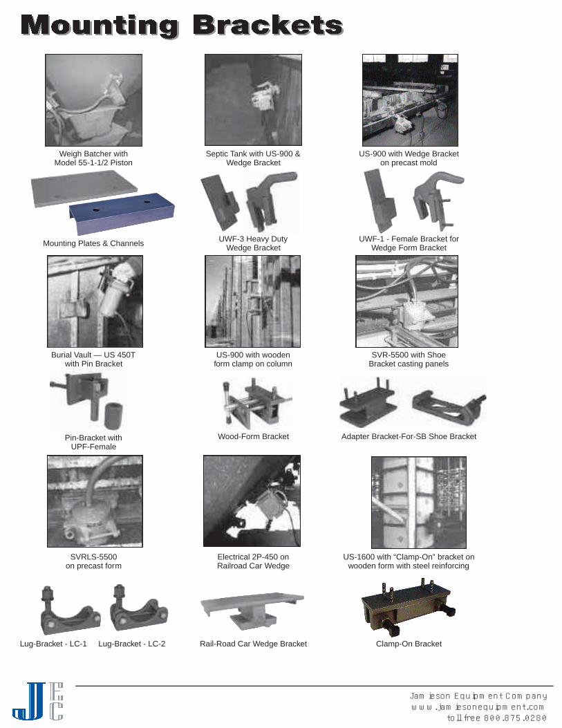
Clamp-On Bracket
Septic Tank with US-900 &Wedge Bracket
Weigh Batcher withModel 55-1-1/2 Piston
US-900 with woodenform clamp on column
Burial Vault — US 450Twith Pin Bracket
SVR-5500 with ShoeBracket casting panels
Adapter Bracket-For-SB Shoe BracketWood-Form BracketPin-Bracket withUPF-Female
Rail-Road Car Wedge Bracket
UWF-1 - Female Bracket forWedge Form Bracket
UWF-3 Heavy DutyWedge Bracket
SVRLS-5500on precast form
Electrical 2P-450 onRailroad Car Wedge
Lug-Bracket - LC-1
US-1600 with “Clamp-On” bracket onwooden form with steel reinforcing
Lug-Bracket - LC-2
Mounting Plates & Channels
US-900 with Wedge Bracketon precast mold
Jamieson Equipment Companywww.jamiesonequipment.com
toll free 800.875.0280
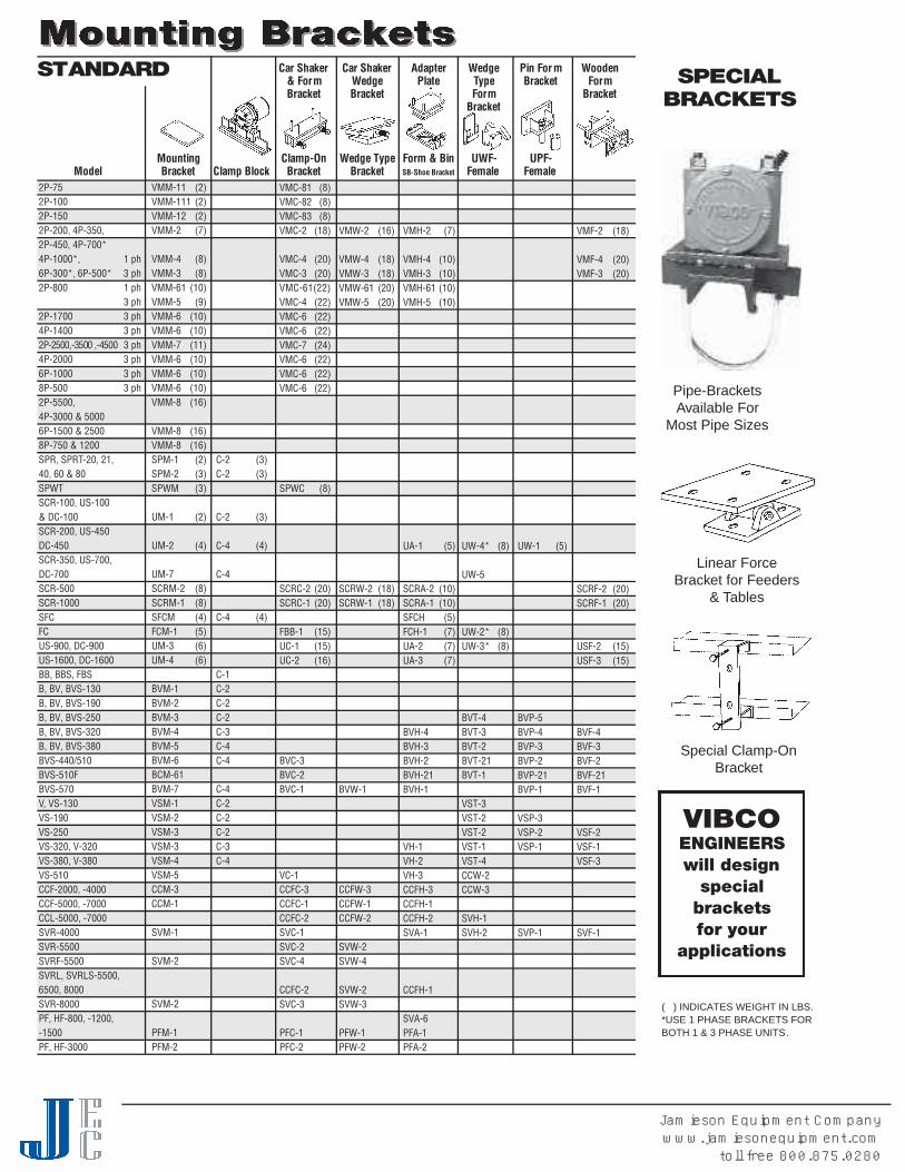
Car Shaker Car Shaker Adapter Wedge Pin For m Wooden& Form Wedge Plate Type Bracket FormBracket Bracket Form Bracket
Bracket
Mounting Clamp-On Wedge Type Form & Bin UWF- UPF-Model Bracket Clamp Block Bracket Bracket SB-Shoe Bracket Female Female
( ) INDICATES WEIGHT IN LBS.*USE 1 PHASE BRACKETS FORBOTH 1 & 3 PHASE UNITS.
VMM-11 (2)VMM-111 (2)VMM-12 (2)VMM-2 (7)
VMM-4 (8)VMM-3 (8)VMM-61 (10)VMM-5 (9)VMM-6 (10)VMM-6 (10)VMM-7 (11)VMM-6 (10)VMM-6 (10)VMM-6 (10)VMM-8 (16)
VMM-8 (16)VMM-8 (16)SPM-1 (2)SPM-2 (3)SPWM (3)
UM-1 (2)
UM-2 (4)
UM-7SCRM-2 (8)SCRM-1 (8)SFCM (4)FCM-1 (5)UM-3 (6)UM-4 (6)
BVM-1BVM-2BVM-3BVM-4BVM-5BVM-6BCM-61BVM-7VSM-1VSM-2VSM-3VSM-3VSM-4VSM-5CCM-3CCM-1
SVM-1
SVM-2
SVM-2
PFM-1PFM-2
C-2 (3)C-2 (3)
C-2 (3)
C-4 (4)
C-4
C-4 (4)
C-1C-2C-2C-2C-3C-4C-4
C-4C-2C-2C-2C-3C-4
VMC-81 (8)VMC-82 (8)VMC-83 (8)VMC-2 (18)
VMC-4 (20)VMC-3 (20)VMC-61(22)VMC-4 (22)VMC-6 (22)VMC-6 (22)VMC-7 (24)VMC-6 (22)VMC-6 (22)VMC-6 (22)
SPWC (8)
SCRC-2 (20)SCRC-1 (20)
FBB-1 (15)UC-1 (15)UC-2 (16)
BVC-3BVC-2BVC-1
VC-1CCFC-3CCFC-1CCFC-2SVC-1SVC-2SVC-4
CCFC-2SVC-3
PFC-1PFC-2
VMW-2 (16)
VMW-4 (18)VMW-3 (18)VMW-61 (20)VMW-5 (20)
SCRW-2 (18)SCRW-1 (18)
BVW-1
CCFW-3CCFW-1CCFW-2
SVW-2SVW-4
SVW-2SVW-3
PFW-1PFW-2
VMH-2 (7)
VMH-4 (10)VMH-3 (10)VMH-61 (10)VMH-5 (10)
UA-1 (5)
SCRA-2 (10)SCRA-1 (10)SFCH (5)FCH-1 (7)UA-2 (7)UA-3 (7)
BVH-4BVH-3BVH-2BVH-21BVH-1
VH-1VH-2VH-3CCFH-3CCFH-1CCFH-2SVA-1
CCFH-1
SVA-6PFA-1PFA-2
UW-4* (8)
UW-5
UW-2* (8)UW-3* (8)
BVT-4BVT-3BVT-2BVT-21BVT-1
VST-3VST-2VST-2VST-1VST-4CCW-2CCW-3
SVH-1SVH-2
UW-1 (5)
BVP-5BVP-4BVP-3BVP-2BVP-21BVP-1
VSP-3VSP-2VSP-1
SVP-1
VMF-2 (18)
VMF-4 (20)VMF-3 (20)
SCRF-2 (20)SCRF-1 (20)
USF-2 (15)USF-3 (15)
BVF-4BVF-3BVF-2BVF-21BVF-1
VSF-2VSF-1VSF-3
SVF-1
S TA N D A R D S P E C I A LB R A C K E T S
Pipe-BracketsAvailable For
Most Pipe Sizes
Linear ForceBracket for Feeders
& Tables
Special Clamp-OnBracket
VIBCOENGINEERSwill design
specialbracketsfor your
applications
2P-752P-1002P-1502P-200, 4P-350,2P-450, 4P-700*4P-1000*, 1 ph6P-300*, 6P-500* 3 ph2P-800 1 ph
3 ph2P-1700 3 ph4P-1400 3 ph2P-2500,-3500 ,-4500 3 ph4P-2000 3 ph6P-1000 3 ph8P-500 3 ph2P-5500,4P-3000 & 50006P-1500 & 25008P-750 & 1200SPR, SPRT-20, 21,40, 60 & 80SPWTSCR-100, US-100& DC-100SCR-200, US-450DC-450SCR-350, US-700,DC-700SCR-500SCR-1000SFCFCUS-900, DC-900US-1600, DC-1600BB, BBS, FBSB, BV, BVS-130B, BV, BVS-190B, BV, BVS-250B, BV, BVS-320B, BV, BVS-380BVS-440/510BVS-510FBVS-570V, VS-130VS-190VS-250VS-320, V-320VS-380, V-380VS-510CCF-2000, -4000CCF-5000, -7000CCL-5000, -7000SVR-4000SVR-5500SVRF-5500SVRL, SVRLS-5500,6500, 8000SVR-8000PF, HF-800, -1200,-1500PF, HF-3000
Jamieson Equipment Companywww.jamiesonequipment.com
toll free 800.875.0280
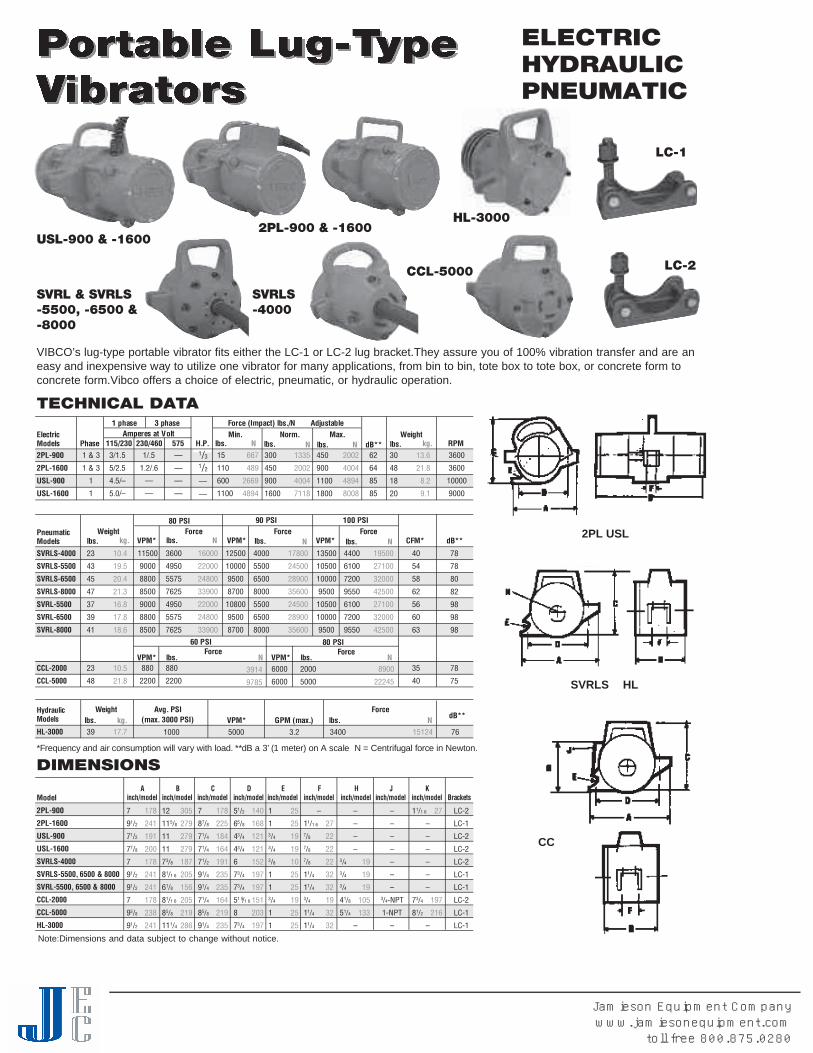
ELECTRICHYDRAULICPNEUMATIC
VIBCO’s lug-type portable vibrator fits either the LC-1 or LC-2 lug bracket.They assure you of 100% vibration transfer and are aneasy and inexpensive way to utilize one vibrator for many applications, from bin to bin, tote box to tote box, or concrete form toconcrete form.Vibco offers a choice of electric, pneumatic, or hydraulic operation.
USL-900 & -1600
SVRL & SVRLS-5500, -6500 &-8000
2PL-900 & -1600
SVRLS-4000
CCL-5000
LC-1
LC-2
2PL USL
SVRLS HL
CC
TECHNICAL DATA
2 P L - 9 0 0
2 P L - 1 6 0 0
U S L - 9 0 0
U S L - 1 6 0 0
1 & 3
1 & 3
1
1
3 / 1 . 5
5 / 2 . 5
4 . 5 / –
5 . 0 / –
—
—
—
—
6 6 7
4 8 9
2 6 6 9
4 8 9 4
3 0 0
4 5 0
9 0 0
1 6 0 0
1 3 3 5
2 0 0 2
4 0 0 4
7 1 1 8
4 5 0
9 0 0
1 1 0 0
1 8 0 0
2 0 0 2
4 0 0 4
4 8 9 4
8 0 0 8
3 0
4 8
1 8
2 0
1 3 . 6
2 1 . 8
8 . 2
9 . 1
E l e c t r i cM o d e l s P h a s e
1 phase 3 phase F o rce (Impact) lbs./N AdjustableA m p e res at Vo l t
H . P. d B * *1 1 5 / 2 3 0 2 3 0 / 4 6 0 5 7 5M i n .
l b s . NM a x .
l b s . Nl b s . NWe i g h t
l b s . k g .6 2
6 4
8 5
8 5
* Frequency and air consumption will va ry with load. **dB a 3’ (1 meter) on A scale N = Centrifugal force in New t o n .
N o rm .
1 / . 5
1 . 2 / . 6
—
—
1 5
1 1 0
6 0 0
1 1 0 0
R P M1/3
1/2
—
—
3 6 0 0
3 6 0 0
1 0 0 0 0
9 0 0 0
1 6 0 0 0
2 2 0 0 0
2 4 8 0 0
3 3 9 0 0
2 2 0 0 0
2 4 8 0 0
3 3 9 0 0
4 0 0 0
5 5 0 0
6 5 0 0
8 0 0 0
5 5 0 0
6 5 0 0
8 0 0 0
1 7 8 0 0
2 4 5 0 0
2 8 9 0 0
3 5 6 0 0
2 4 5 0 0
2 8 9 0 0
3 5 6 0 0
4 4 0 0
6 1 0 0
7 2 0 0
9 5 5 0
6 1 0 0
7 2 0 0
9 5 5 0
1 9 5 0 0
2 7 1 0 0
3 2 0 0 0
4 2 5 0 0
2 7 1 0 0
3 2 0 0 0
4 2 5 0 0
2 3
4 3
4 5
4 7
3 7
3 9
4 1
2 3
4 8
3 9
1 0 . 4
1 9 . 5
2 0 . 4
2 1 . 3
1 6 . 8
1 7 . 8
1 8 . 6
1 0 . 5
2 1 . 8
1 7 . 7
P n e u m a t i cM o d e l s
80 PSI
d B * *F o rc e
l b s . NF o rc e
l b s . Nl b s . NWe i g h t
l b s . k g .
7 8
7 8
8 0
8 2
9 8
9 8
9 8
7 8
7 5
F o rc e
3 6 0 0
4 9 5 0
5 5 7 5
7 6 2 5
4 9 5 0
5 5 7 5
7 6 2 5
8 8 0
2 2 0 0
V P M *
1 1 5 0 0
9 0 0 0
8 8 0 0
8 5 0 0
9 0 0 0
8 8 0 0
8 5 0 0
8 8 0
2 2 0 0
C F M *
4 0
5 4
5 8
6 2
5 6
6 0
6 3
3 5
4 0
V P M *
1 2 5 0 0
1 0 0 0 0
9 5 0 0
8 7 0 0
1 0 8 0 0
9 5 0 0
8 7 0 0
V P M *
1 3 5 0 0
1 0 5 0 0
1 0 0 0 0
9 5 0 0
1 0 5 0 0
1 0 0 0 0
9 5 0 0
90 PSI 100 PSI
S V R L S - 4 0 0 0
S V R L S - 5 5 0 0
S V R L S - 6 5 0 0
S V R L S - 8 0 0 0
S V R L - 5 5 0 0
S V R L - 6 5 0 0
S V R L - 8 0 0 0
C C L- 2 0 0 0
C C L - 5 0 0 0
H y d r a u l i cM o d e l s
H L - 3 0 0 0
60 PSIF o rc e
l b s . N l b s . NF o rc e
V P M * V P M *
80 PSI
3 9 1 4
9 7 8 5
6 0 0 0
6 0 0 0
2 0 0 0
5 0 0 0
8 9 0 0
2 2 2 4 5
We i g h tl b s . k g .
Avg. PSI(max. 3000 PSI) V P M * GPM (max.) l b s . N
F o rc ed B * *
1 0 0 0 5 0 0 0 3 . 2 3 4 0 0 1 5 1 2 4 7 6
M o d e l
2 P L - 9 0 0
2 P L - 1 6 0 0
U S L - 9 0 0
U S L - 1 6 0 0
S V R L S - 4 0 0 0
SVRLS-5500, 6500 & 8000
SVRL-5500, 6500 & 8000
C C L - 2 0 0 0
C C L - 5 0 0 0
H L - 3 0 0 0
Ainch/model
Binch/model
Cinch/model
Dinch/model
Einch/model
Finch/model
Hinch/model
Jinch/model
Kinch/model Brackets
DIMENSIONS
1 7 8
2 4 1
1 9 1
2 0 0
1 7 8
2 4 1
2 4 1
1 7 8
2 3 8
2 4 1
7
91/2
71/2
77/8
7
91/2
91/2
7
93/8
91/2
3 0 5
2 7 9
2 7 9
2 7 9
1 8 7
2 0 5
1 5 6
2 0 5
2 1 9
2 8 6
1 2
1 15/8
1 1
1 1
73/8
81/1 6
61/8
81/1 6
85/8
1 11/4
1 7 8
2 2 5
1 8 4
1 6 4
1 9 1
2 3 5
2 3 5
1 6 4
2 1 9
2 3 5
7
87/8
71/4
71/4
71/2
91/4
91/4
71/4
85/8
91/4
1 4 0
1 6 8
1 2 1
1 2 1
1 5 2
1 9 7
1 9 7
1 5 1
2 0 3
1 9 7
51/2
65/8
43/4
43/4
6
73/4
73/4
51 5/1 6
8
73/4
2 5
2 5
1 9
1 9
1 0
2 5
2 5
1 9
2 5
2 5
1
13/4
3/4
3/8
1
13/4
1
1
2 7
2 2
2 2
2 2
3 2
3 2
1 9
3 2
3 2
–
11/1 6
7/8
7/8
7/8
11/4
11/4
3/4
11/4
11/4
1 9
1 9
1 9
1 0 5
1 3 3
–
–
–
–3/43/43/4
41/8
51/4
–
–
–
–
–
–
–
–3/4- N P T
1 - N P T
–
2 7
1 9 7
2 1 6
11/1 6
–
–
–
–
–
–
73/4
81/2
–
L C - 2
L C - 1
L C - 2
L C - 2
L C - 2
L C - 1
L C - 1
L C - 2
L C - 1
L C - 1
HL-3000
Note:Dimensions and data subject to change without notice.
Jamieson Equipment Companywww.jamiesonequipment.com
toll free 800.875.0280
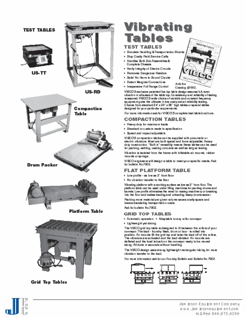
Jamieson Equipment Companywww.jamiesonequipment.com
toll free 800.875.0280

Jamieson Equipment Companywww.jamiesonequipment.com
toll free 800.875.0280

Jamieson Equipment Companywww.jamiesonequipment.com
toll free 800.875.0280

PISTON AIRModel 44 carshaker haswedge bracket to fit car’sfemale Dove-tail receptacle.Available in powerful 3” bore sizes tohelp evacuate hopper cars quickly.
The lightweight, ease of portability, low cost and high forces ofModel 44 carshaker has proven highly desirable for the small tomedium consumer. See page 18 for technical data under 3” piston vibrators.
BIG BUSTERBig Buster carshakers provide high force at low frequency. Thesmaller units are supplied with wedge bracket PFW-1500, and withbuilt-in clamp-on bracket as PC-3500 and PC-8000. For moreinformation, see page 21 & 22.
ELECTRICThe VIBCO electric carshakers use the heavy duty line electric - 2P vibrators with their heavy duty reliability and perfo rm a n c e. S i n g l ephase operation offered up to model 2P-800, three phase in allm o d e l s. Wedge bra cket to fit female receptacle on railroad car offe r e dup to model 2P-800; clamp-on bra cket ava i l a ble for all models. a l lmodels have ove rload protection and adjustable eccentrics prov i d i n gf l exibility to meet changes brought about by changes brought about bychanges in density of car contents. See page 25-28 for technical data.
F E AT U R E S :• P O RTABLE • POWERFUL • QUIET • RUGGED • RELIABLE• QUICK MOUNT! Clamp-on or Wedge • SAFE • LOW COST• LOW MAINTENANCE
YOUR BEST CHOICE . . .
ROTARY PISTON - CCW-5000Your best choice of all pneumatic railroad carshakers. This patentedunit developed by VIBCO accomplishes 3 vital functions:
1. It will empty the most stubborn materials.
2. It is silent, no more sound than an electric motor. (72-75 dB)
3. Low air consumption compared to other pneumatic units.
Other features are: No lubrication needed: Can easily be repaired bymaintenance department.
HIGH FREQUENCY AIR - SVRWSYour second best choice for railroad carshakers, these units will movethe most stubborn materials. The silent SVRWS (80-85 dB) withwedge head comes in 2 sizes, SVRWS-5500 and 6500.
Virtually no material can stand up to the high force and 10000 VPM(vibrations per minute) these units create.
The high frequency units can also be supplied with clamp-onbrackets, SVRC-5500, 6500 & 8000.
For more information see Catalog #9126.
Ask for Catalog #9126
MODEL VMW ON MODEL VMC ON MODEL PC-3500 MODEL 44-3WEDGE BRACKET CLAMP BRACKET
ROTARY ROLLERSVRWS-5500,SVRWS-6500
ROTARY PISTONCCW-5000
Jamieson Equipment Companywww.jamiesonequipment.com
toll free 800.875.0280
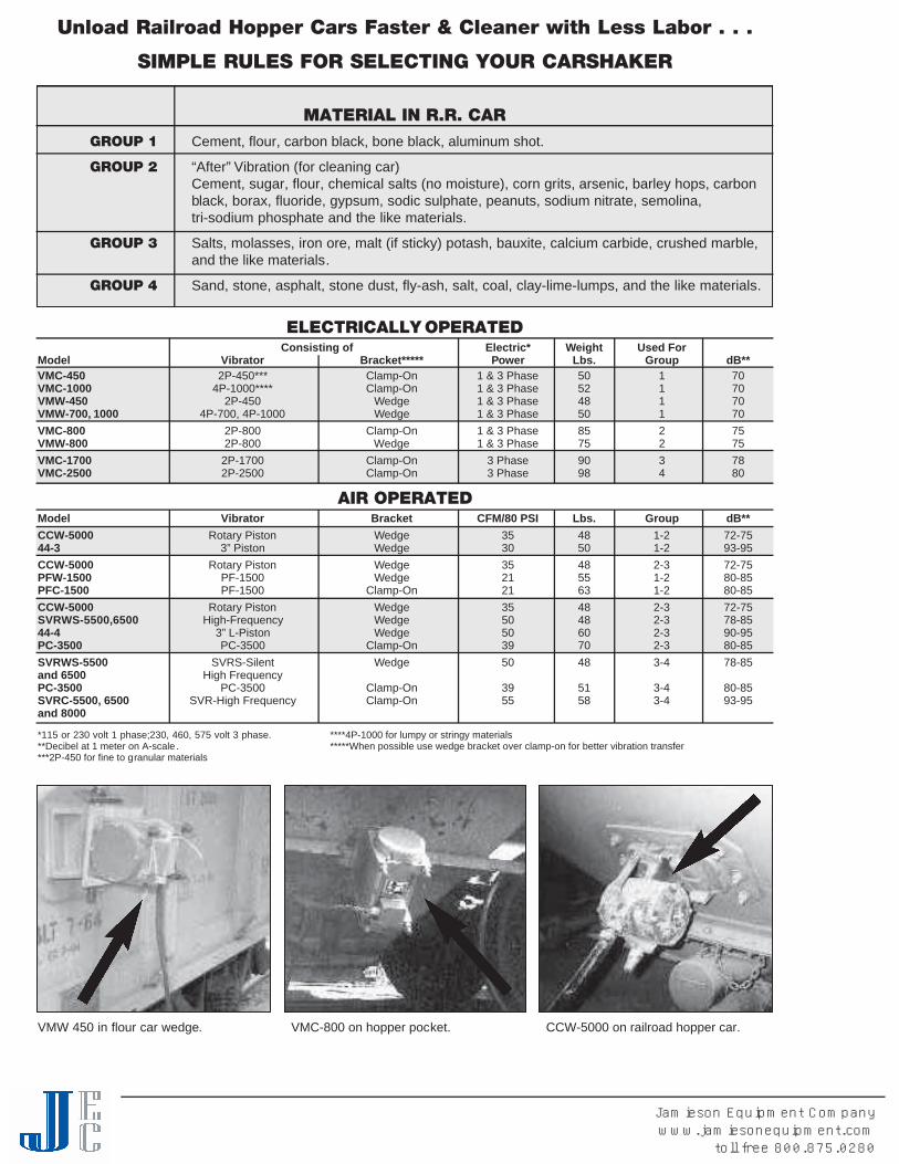
Unload Railroad Hopper Cars Faster & Cleaner with Less Labor . . .
SIMPLE RULES FOR SELECTING YOUR CARSHAKER
MATERIAL IN R.R. CAR
GROUP 1 Cement, flour, carbon black, bone black, aluminum shot.
GROUP 2 “After” Vibration (for cleaning car)Cement, sugar, flour, chemical salts (no moisture), corn grits, arsenic, barley hops, carbonblack, borax, fluoride, gypsum, sodic sulphate, peanuts, sodium nitrate, semolina,tri-sodium phosphate and the like materials.
GROUP 3 Salts, molasses, iron ore, malt (if sticky) potash, bauxite, calcium carbide, crushed marble,and the like materials.
GROUP 4 Sand, stone, asphalt, stone dust, fly-ash, salt, coal, clay-lime-lumps, and the like materials.
VMW 450 in flour car wedge. VMC-800 on hopper pocket. CCW-5000 on railroad hopper car.
ELECTRICALLY OPERATEDConsisting of Electric* Weight Used For
Model Vibrator Bracket***** Power Lbs. Group dB**VMC-450 2P-450*** Clamp-On 1 & 3 Phase 50 1 70VMC-1000 4P-1000**** Clamp-On 1 & 3 Phase 52 1 70VMW-450 2P-450 Wedge 1 & 3 Phase 48 1 70VMW-700, 1000 4P-700, 4P-1000 Wedge 1 & 3 Phase 50 1 70VMC-800 2P-800 Clamp-On 1 & 3 Phase 85 2 75VMW-800 2P-800 Wedge 1 & 3 Phase 75 2 75VMC-1700 2P-1700 Clamp-On 3 Phase 90 3 78VMC-2500 2P-2500 Clamp-On 3 Phase 98 4 80
AIR OPERATEDModel Vibrator Bracket CFM/80 PSI Lbs. Group dB**CCW-5000 Rotary Piston Wedge 35 48 1-2 72-7544-3 3” Piston Wedge 30 50 1-2 93-95CCW-5000 Rotary Piston Wedge 35 48 2-3 72-75PFW-1500 PF-1500 Wedge 21 55 1-2 80-85PFC-1500 PF-1500 Clamp-On 21 63 1-2 80-85CCW-5000 Rotary Piston Wedge 35 48 2-3 72-75SVRWS-5500,6500 High-Frequency Wedge 50 48 2-3 78-8544-4 3” L-Piston Wedge 50 60 2-3 90-95PC-3500 PC-3500 Clamp-On 39 70 2-3 80-85SVRWS-5500 SVRS-Silent Wedge 50 48 3-4 78-85and 6500 High FrequencyPC-3500 PC-3500 Clamp-On 39 51 3-4 80-85SVRC-5500, 6500 SVR-High Frequency Clamp-On 55 58 3-4 93-95and 8000
*115 or 230 volt 1 phase;230, 460, 575 volt 3 phase. ****4P-1000 for lumpy or stringy materials**Decibel at 1 meter on A-scale. *****When possible use wedge bracket over clamp-on for better vibration transfer***2P-450 for fine to granular materials
Jamieson Equipment Companywww.jamiesonequipment.com
toll free 800.875.0280