Embed Size (px)
Citation preview

EENG223: CIRCUIT THEORY I
DC Circuits:
Operational Amplifiers Hasan Demirel
EENG223: CIRCUIT THEORY I
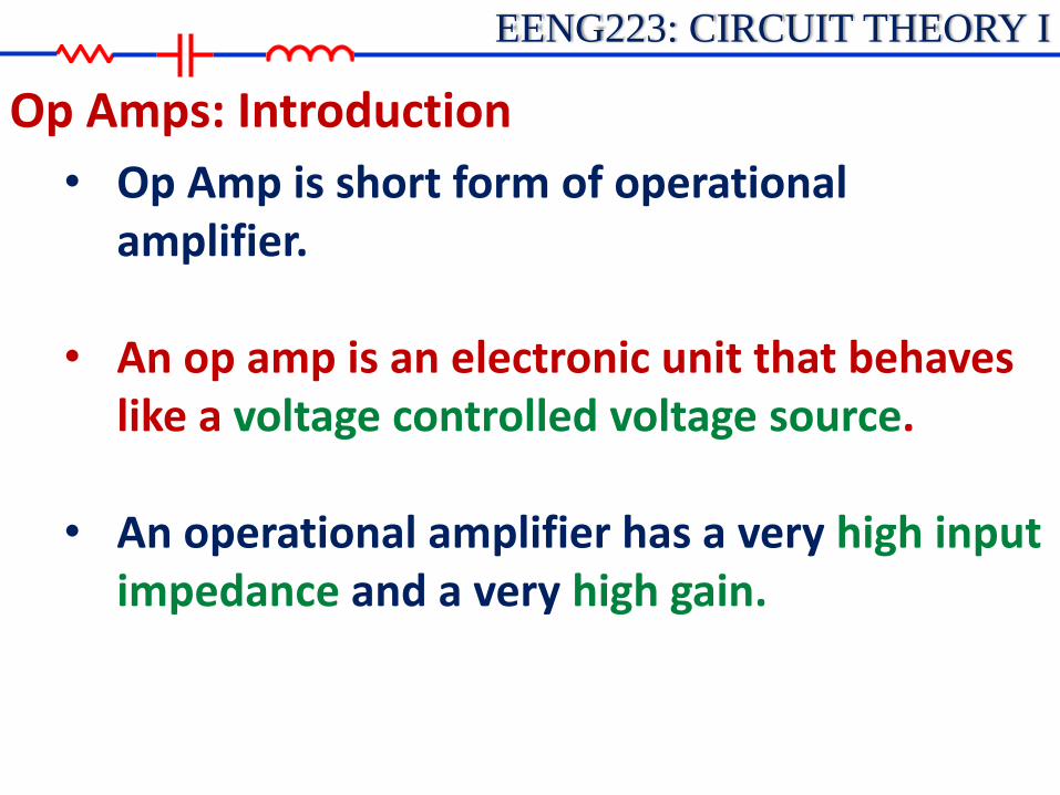
• Op Amp is short form of operational amplifier.
• An op amp is an electronic unit that behaves like a voltage controlled voltage source.
• An operational amplifier has a very high input
impedance and a very high gain.
Op Amps: Introduction

EENG223: CIRCUIT THEORY I
• Op amps can be configured in many different ways using resistors and other components.
• Most configurations use feedback.
• An op amp can be designed to perform mathematical operations of addition, subtraction, multiplication, division, differentiation, and integration.
Op Amps: Use of Op Amps
EENG223: CIRCUIT THEORY I
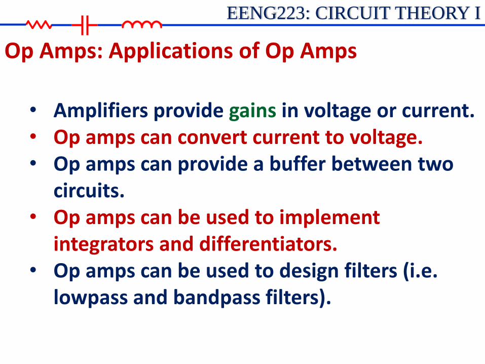
• Amplifiers provide gains in voltage or current. • Op amps can convert current to voltage. • Op amps can provide a buffer between two
circuits. • Op amps can be used to implement
integrators and differentiators. • Op amps can be used to design filters (i.e.
lowpass and bandpass filters).
Op Amps: Applications of Op Amps
EENG223: CIRCUIT THEORY I
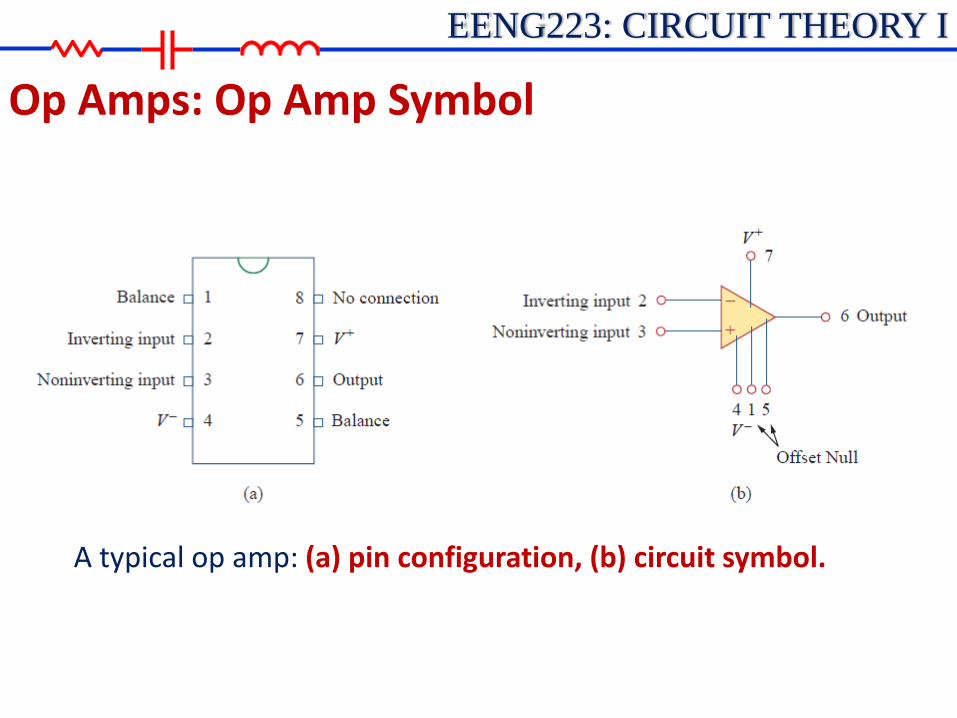
Op Amps: Op Amp Symbol
A typical op amp: (a) pin configuration, (b) circuit symbol.
EENG223: CIRCUIT THEORY I
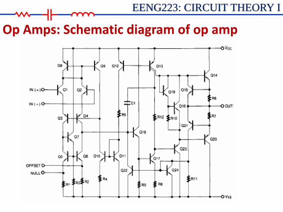
Op Amps: Schematic diagram of op amp
EENG223: CIRCUIT THEORY I
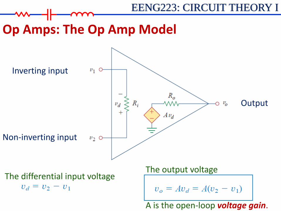
Op Amps: The Op Amp Model
Inverting input
Non-inverting input
Output
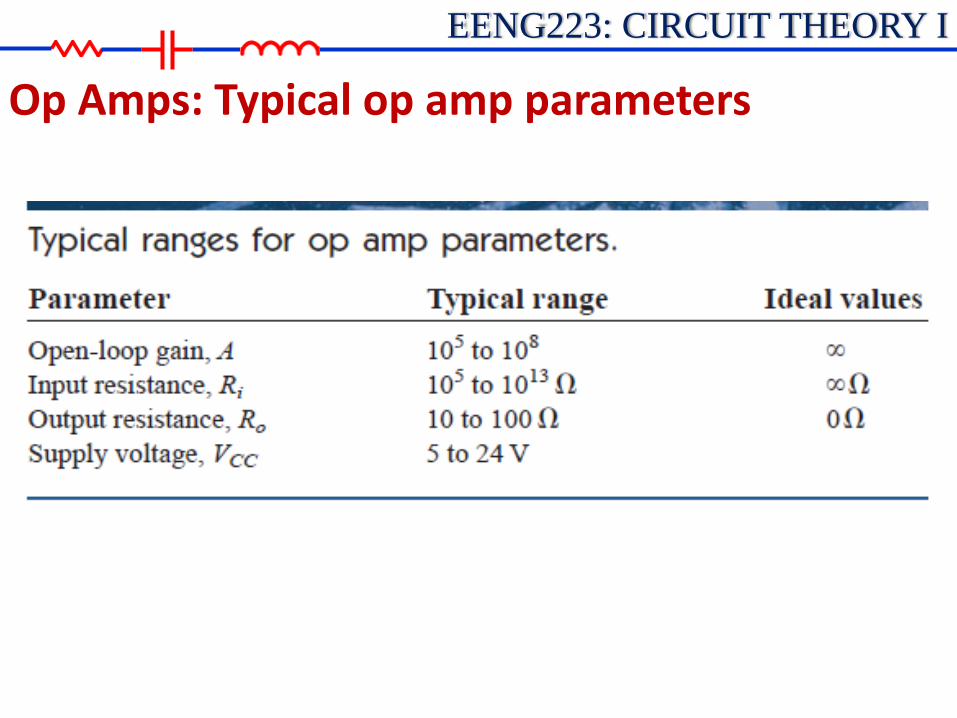
The differential input voltage The output voltage
A is the open-loop voltage gain.
EENG223: CIRCUIT THEORY I
Op Amps: Typical op amp parameters
EENG223: CIRCUIT THEORY I
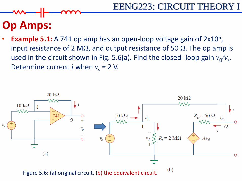
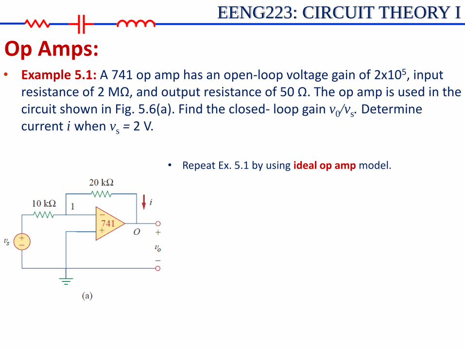
Op Amps: • Example 5.1: A 741 op amp has an open-loop voltage gain of 2x10⁵,
input resistance of 2 MΩ, and output resistance of 50 Ω. The op amp is used in the circuit shown in Fig. 5.6(a). Find the closed- loop gain v0/vs. Determine current i when vs = 2 V.
Figure 5.6: (a) original circuit, (b) the equivalent circuit.

EENG223: CIRCUIT THEORY I
Op Amps: • Example 5.1: A 741 op amp has an open-loop voltage gain of 2x10⁵,
input resistance of 2 MΩ, and output resistance of 50 Ω. The op amp is used in the circuit shown in Fig. 5.6(a). Find the closed- loop gain v0/vs. Determine current i when vs = 2 V.
Apply KCL at node 1:
Apply KCL at node 0:
(1)
(2)
EENG223: CIRCUIT THEORY I
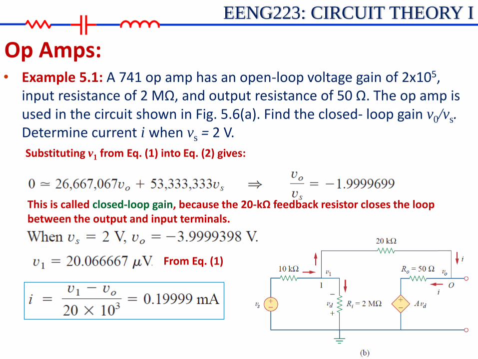
Op Amps: • Example 5.1: A 741 op amp has an open-loop voltage gain of 2x10⁵,
input resistance of 2 MΩ, and output resistance of 50 Ω. The op amp is used in the circuit shown in Fig. 5.6(a). Find the closed- loop gain v0/vs. Determine current i when vs = 2 V.
Substituting v1 from Eq. (1) into Eq. (2) gives:
This is called closed-loop gain, because the 20-kΩ feedback resistor closes the loop between the output and input terminals.
From Eq. (1)

EENG223: CIRCUIT THEORY I
Op Amps: Ideal Op Amp • An ideal op amp is an amplifier with infinite open-loop
gain, infinite input resistance, and zero output resistance. • To facilitate the understanding of op amp circuits, we will assume
ideal op amps. An op amp is ideal if it has the following characteristics:
1. Infinite open-loop gain, A = ∞
2. Infinite input resistance, Rin=∞
3. Zero output resistance, Ro=0

EENG223: CIRCUIT THEORY I
Op Amps: Ideal Op Amp • An ideal op amp is an amplifier with infinite open-loop
gain, infinite input resistance, and zero output resistance.
1. Ideal Op Amp Model
1. Infinite open-loop gain, A = ∞
2. Infinite input resistance, Rin=∞
3. Zero output resistance, Ro=0

EENG223: CIRCUIT THEORY I
Op Amps: Ideal Op Amp • Two important characteristics of the ideal op amp are:
1. The currents into both input terminals are zero. This is due to infinite input resistance. An infinite resistance between the input terminals implies that an open circuit exists there and current cannot enter the op amp.
2. The voltage across the input terminals is equal to zero.
An ideal op amp has zero current into its two input terminals and the voltage difference between the two input terminals is equal to zero.
EENG223: CIRCUIT THEORY I
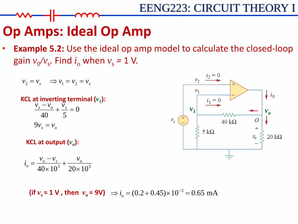
Op Amps: Ideal Op Amp • Example 5.2: Use the ideal op amp model to calculate the closed-loop
gain v0/vs. Find io when vs = 1 V.
(if vs = 1 V , then vo = 9V)
vo v1
KCL at inverting terminal (v1):
ss vvvvv 212
os
sos
vv
vvv
9
0540
KCL at output (vo):
33 10201040
oso
o
vvvi
mA65.010)45.02.0( 3
oi

EENG223: CIRCUIT THEORY I
Op Amps: Inverting Amplifier • Both the input signal and the feedback are applied at the
inverting terminal of the op amp.
Noninverting terminal is grounded.
Applying KCL at node 1:
• An inverting amplifier reverses the polarity of the input signal while amplifying it.
EENG223: CIRCUIT THEORY I
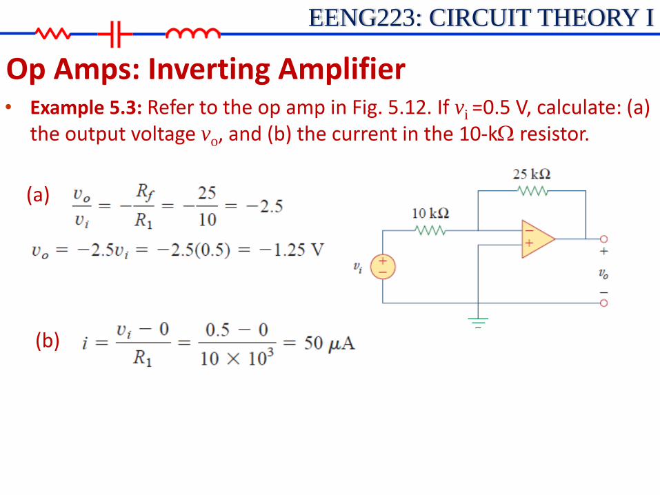
Op Amps: Inverting Amplifier • Example 5.3: Refer to the op amp in Fig. 5.12. If vi =0.5 V, calculate: (a)
the output voltage vo, and (b) the current in the 10-kW resistor.
(a)
(b)

EENG223: CIRCUIT THEORY I
Op Amps: Inverting Amplifier • Practice Problem 5.3: Find the output of the op amp circuit shown in Fig.
5.13. Calculate the current through the feedback resistor.
EENG223: CIRCUIT THEORY I
Op Amps: • Example 5.1: A 741 op amp has an open-loop voltage gain of 2x10⁵, input
resistance of 2 MΩ, and output resistance of 50 Ω. The op amp is used in the circuit shown in Fig. 5.6(a). Find the closed- loop gain v0/vs. Determine current i when vs = 2 V.
• Repeat Ex. 5.1 by using ideal op amp model.
EENG223: CIRCUIT THEORY I
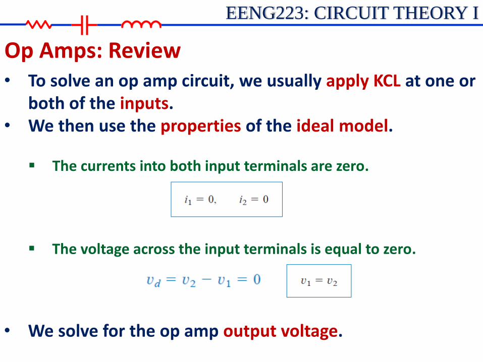
Op Amps: Review • To solve an op amp circuit, we usually apply KCL at one or
both of the inputs. • We then use the properties of the ideal model.
The currents into both input terminals are zero.
• We solve for the op amp output voltage.
The voltage across the input terminals is equal to zero.
EENG223: CIRCUIT THEORY I
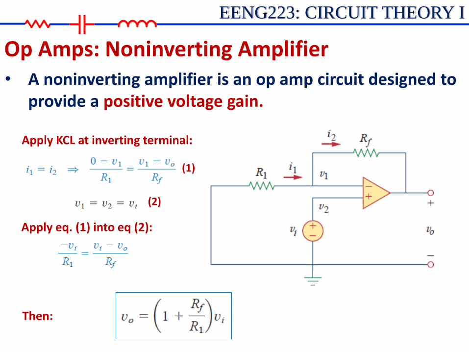
Op Amps: Noninverting Amplifier • A noninverting amplifier is an op amp circuit designed to
provide a positive voltage gain.
Apply KCL at inverting terminal:
(1)
(2)
Apply eq. (1) into eq (2):
Then:
EENG223: CIRCUIT THEORY I
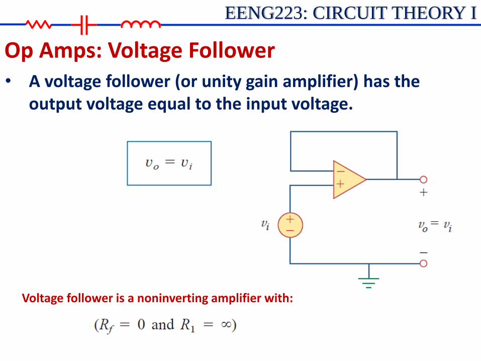
Op Amps: Voltage Follower • A voltage follower (or unity gain amplifier) has the
output voltage equal to the input voltage.
Voltage follower is a noninverting amplifier with:

EENG223: CIRCUIT THEORY I
Op Amps: Noninverting Amplifier • Example 5.5: For the op amp circuit below, calculate the output
voltage vo .
EENG223: CIRCUIT THEORY I
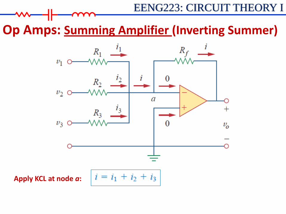
Op Amps: Summing Amplifier (Inverting Summer)
Apply KCL at node a:

EENG223: CIRCUIT THEORY I
Op Amps: Summing Amplifier (Inverting Summer)
Apply KCL at node a:
Note that
Then,
EENG223: CIRCUIT THEORY I
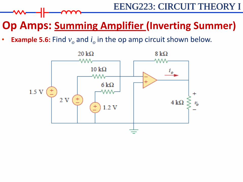
Op Amps: Summing Amplifier (Inverting Summer) • Example 5.6: Find vo and io in the op amp circuit shown below.
EENG223: CIRCUIT THEORY I
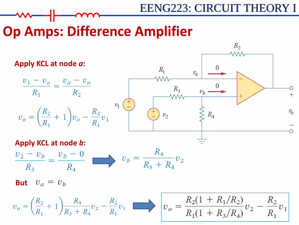
Op Amps: Difference Amplifier
Apply KCL at node a:
Apply KCL at node b:
But

EENG223: CIRCUIT THEORY I
Op Amps: Difference Amplifier • Difference amplifier must reject a signal common to the two
inputs, the amplifier must have the property that vo=0, when v1= v2.
• This property exists when:
• When this property is satisfied • The op amp circuit is a difference amplifier
• If R2 = R1 and R3 = R4 •The difference amplifier becomes •A subtractor circuit:

EENG223: CIRCUIT THEORY I
Op Amps: Cascaded Op Amp Circuits • A cascade connection is a head-to-tail arrangement of two or more
op amp circuits such that the output of one is the input of the next.
• The overall gain of the cascade connection is the product of the gains of the individual op amp circuits

EENG223: CIRCUIT THEORY I
Op Amps: Cascaded Op Amp Circuits • Example 5.9: Find v0 and i0 in the circuit below.
EENG223: CIRCUIT THEORY I
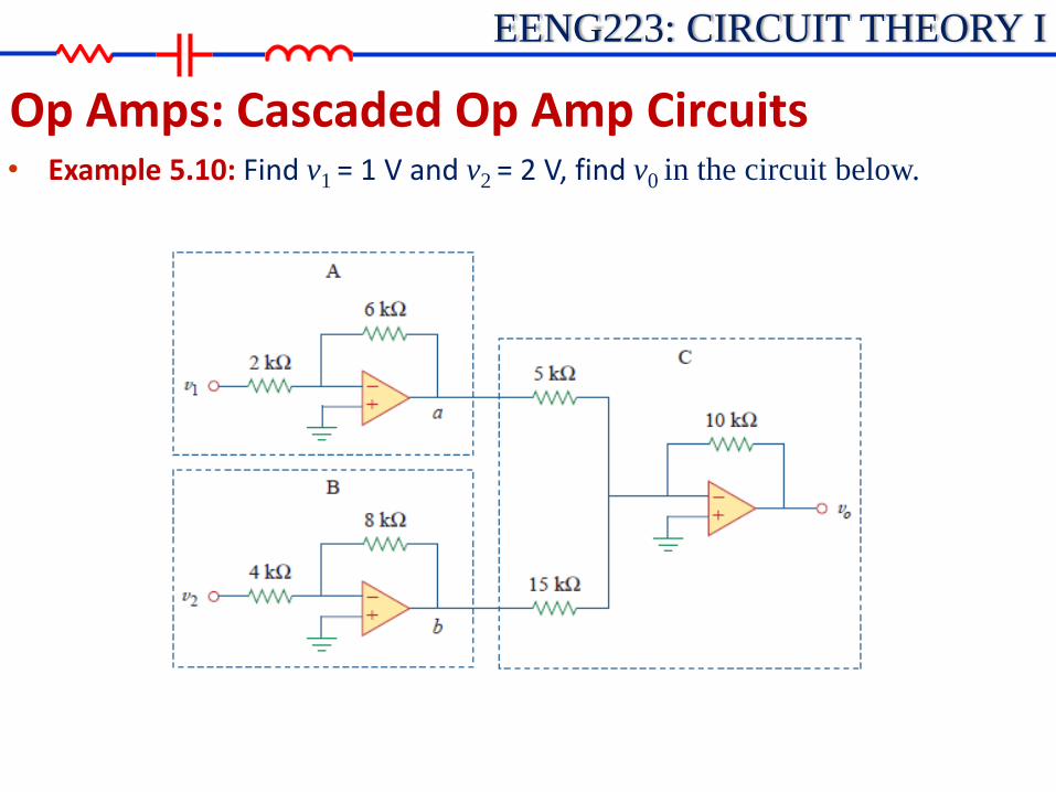
Op Amps: Cascaded Op Amp Circuits • Example 5.10: Find v1 = 1 V and v2 = 2 V, find v0 in the circuit below.