Embed Size (px)
Citation preview
1
FL7MSeries
ORDER GUIDE
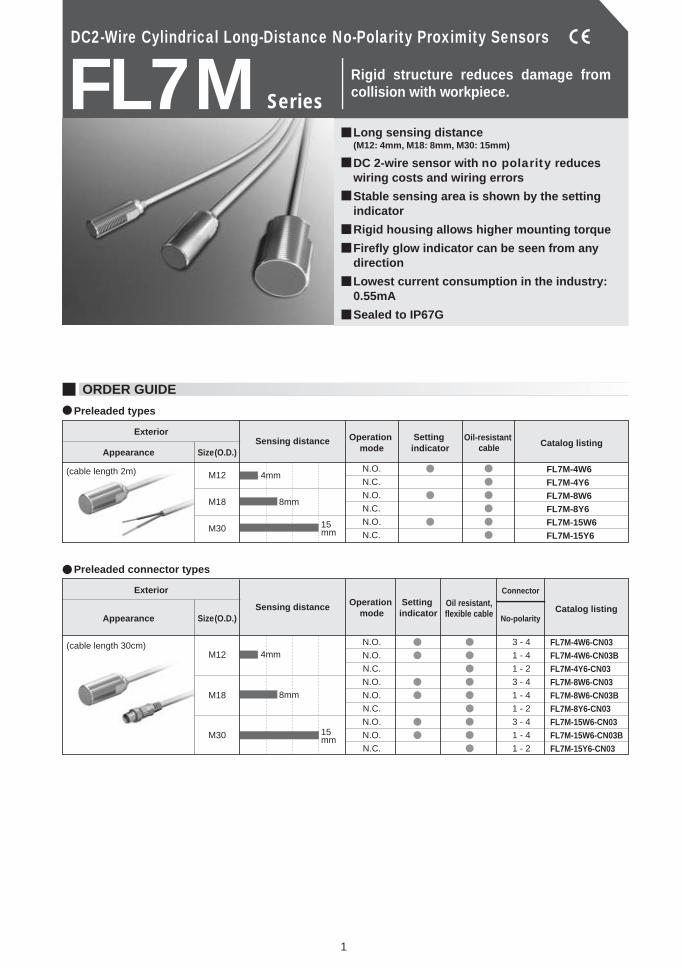
Rigid structure reduces damage from collision with workpiece.
DC2-Wire Cylindrical Long-Distance No-Polarity Proximity Sensors
Long sensing distance (M12: 4mm, M18: 8mm, M30: 15mm)
DC 2-wire sensor with no polarity reduces wiring costs and wiring errors
Stable sensing area is shown by the setting indicator
Rigid housing allows higher mounting torque
Firefly glow indicator can be seen from any direction
Lowest current consumption in the industry: 0.55mA
Sealed to IP67G
Exterior
Appearance Size (O.D.)
Operation mode Catalog listingSensing distance
(cable length 2m) M12
M18
M30
4mm
8mm
15mm
N.O.
N.C.
N.O.
N.C.
N.O.
N.C.
FL7M-4W6FL7M-4Y6FL7M-8W6FL7M-8Y6FL7M-15W6FL7M-15Y6
Exterior
Appearance Size (O.D.)
Operation mode
Setting indicator Catalog listingSensing distance
M12
M18
M30
4mm
8mm
15mm
N.O.
N.O.
N.C.
N.O.
N.O.
N.C.
N.O.
N.O.
N.C.
3 - 4
1 - 4
1 - 2
3 - 4
1 - 4
1 - 2
3 - 4
1 - 4
1 - 2
Oil-resistant cable
Connector
No-polarity
FL7M-4W6-CN03FL7M-4W6-CN03BFL7M-4Y6-CN03FL7M-8W6-CN03FL7M-8W6-CN03BFL7M-8Y6-CN03FL7M-15W6-CN03FL7M-15W6-CN03BFL7M-15Y6-CN03
(cable length 30cm)
Oil resistant,flexible cable
Preleaded types
Preleaded connector types
Setting indicator
2
Name Appearance O.D. Catalog listing
Mounting bracket
Protective cover
Spatter-guarded protective cover
For M12
For M18
For M30
For M12
For M18
For M30
For M8
For M12
For M18
For M30
FL-PA112
FL-PA118
FL-PA130
FL-PA12
FL-PA18
FL-PA30
FL-PA08W
FL-PA12W
FL-PA18W
FL-PA30W
Actuation methodRated sensing distanceUsable sensing distanceStandard target objectDifferential travelRated supply voltageOperating voltage rangeLeakage currentOutput operational mode
Control output
Operating frequencyTemperature driftSupply voltage drift
Indicator lamps
Operating temperatureInsulation resistanceDielectric strengthVibration resistance Shock resistanceProtective structureWeight (preleaded type)Circuit protectionWiring method
Material
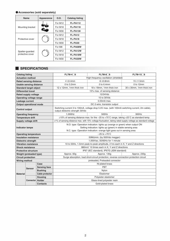
SPECIFICATIONS
High-frequency oscillation (shielded)
15% max. of sensing distance
12/24Vdc
10 to 30Vdc
0.55mA max.
DC 2-wire, transistor output
±10% of sensing distance max. for the –25 to +70˚C range, taking +25˚C as standard temp.
±1% of sensing distance max. with 15% voltage fluctuation, taking rated supply voltage as standard voltage
–25 to +70˚C
50MΩmin. (by 500Vdc megger)
1,000Vac, 50/60Hz for 1 minute
10 to 55Hz, 1.5mm peak-to-peak amplitude, 2 hrs each in X, Y and Z directions
980m/s2 10 times each in X, Y and Z directions
IP67 (IEC standard), IP67G (JEM standard)
Surge absorption, load short-circuit protection, reverse connection protection circuit
preleaded, Preleaded connector
Ni-plated brass
PBT
Nylon
Elastomer
Polyester elastomer
Glass-lined polyester resin
Gold-plated brass
Catalog listing
Sensor
CaseSensing faceBushingCable protectorHousingHolderContacts
Connector
4 ±0.4mm
0 to 3.2mm
12 x 12mm, 1mm thick iron
8 ±0.8mm
0 to 6.4mm
18 x 18mm, 1mm thick iron
Approx. 130gApprox. 60g Approx. 230g
15 ±1.5mm
0 to 12mm
30 x 30mm, 1mm thick iron
Switching current 3 to 100mA, voltage drop 5.0V max. (with 100mA switching current, 2m cable), output dielectric strength 30Vdc
1,000Hz 500Hz 300Hz
N.O. type: Operation indication: lights up (orange or green) when output ON Setting indication: lights up (green) in stable sensing area N.C. type: Operation indication: orange light goes out in sensing area
Accessories (sold separately)
FL7M-4 6 FL7M-8 6 FL7M-15 6
3
FL7M-4 6 FL7M-8 6 FL7M-15 6
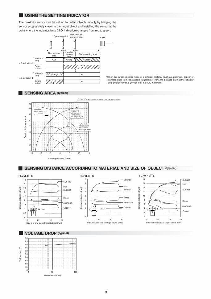
USING THE SETTING INDICATOR
The proximity sensor can be set up to detect objects reliably by bringing the
sensor progressively closer to the target object and installing the sensor at the
point where the indicator lamp (N.O. indication) changes from red to green.
SENSING DISTANCE ACCORDING TO MATERIAL AND SIZE OF OBJECT (typical)
Size d of one side of target object (mm)
Copper
Aluminum
Brass
SUS304
Iron
SUS430
Sen
sing
dis
tanc
e x
(mm
)
Sen
sing
dis
tanc
e x
(mm
)
Sen
sing
dis
tanc
e x
(mm
)
0 20 40 60
4.5
4 3.5
3
2.5
2
1.5
1
0.5
0
Size d of one side of target object (mm)
Copper
Aluminum
Brass
SUS304
Iron
SUS430
0 20 40 60
9
8
7
6
5
4
3
2
1
0
18
16
14
12
10
8
6
4
2
0
Size d of one side of target object (mm)
Copper
Aluminum
Brass
SUS304
Iron
SUS430
0 20 40 60
SENSING AREA (typical)
Operating point
Non-sensing area
Stable sensing areaUnstable sensing
area
N.O. indication
N.C. indication
Max. 80% of operating point
Indicator lamp
Control output
Indicator lamp
Control output
Out
Out
Out
Orang Green
Orange
-15 -10 -5 0 5 10 15
16
14
12
10
8
6
4
2
0
FL7M-15 6 with standard 30x30x1mm iron target object
Sen
sing
dis
tanc
e x
(mm
)
FL7M-4 6 with standard 12x12x1mm iron target object
FL7M-8 6 with standard 18x18x1mm iron target object
Sensing distance X (mm)
Standard target object
VOLTAGE DROP (typical)
Load current (mA)
Vol
tage
dro
p (V
)
1 10 100
5.0
4.5
4.0
3.5
3.0
2.5
2.0
1.5
1.0
0.5
0
*When the target object is made of a different material (such as aluminum, copper or stainless steel) from the standard target object (iron), the distance at which the indicator lamp changes color is shorter than the 80% maximum.
FL7M
4
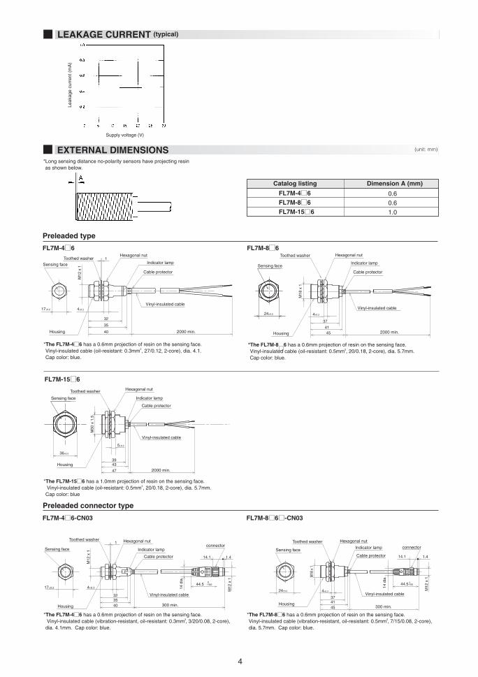
LEAKAGE CURRENT (typical)
Leak
age
curr
ent (
mA
)
Supply voltage (V)
Catalog listing Dimension A (mm)
0.6
0.6
1.0
EXTERNAL DIMENSIONS
Toothed washer
17±0.2 4±0.2
M12
x 1
32
35
40 2000 min.
Hexagonal nut
Indicator lamp
Vinyl-insulated cable
1
Housing
Sensing face
Cable protector
Toothed washer
37
4±0.2
4145
M18
x 1
2000 min.
Hexagonal nut
Indicator lamp
Vinyl-insulated cable
Housing
Sensing face
Cable protector
Toothed washer
3943
47
M30
x 1
.5
2000 min.
Hexagonal nut
Indicator lamp
Vinyl-insulated cable
Housing
Sensing face
Cable protector
24±0.2
36±0.2
5±0.3
Preleaded connector type
Toothed washer
17±0.244.5
4±0.2
32
1
14.1 1.4
3540
M12
x 1
M12
x 1
14 d
ia.
300 min.
Hexagonal nut
Indicator lamp
Vinyl-insulated cable
Cable protector
connector
Housing
Sensing face
0 -100
Toothed washer
24±0.2
37
4541
4±0.2
M18
x 1
M12
x 1
14 d
ia.
300 min.
14.1 1.4
Hexagonal nut
Indicator lamp connector
Vinyl-insulated cable
Housing
Sensing faceCable protector
44.5-1000
(unit: mm)
*Long sensing distance no-polarity sensors have projecting resin as shown below.
FL7M-4 6FL7M-8 6 FL7M-15 6
*The FL7M-4 6 has a 0.6mm projection of resin on the sensing face. Vinyl-insulated cable (oil-resistant: 0.3mm2, 27/0.12, 2-core), dia. 4.1. Cap color: blue.
*The FL7M-8 6 has a 0.6mm projection of resin on the sensing face. Vinyl-insulated cable (oil-resistant: 0.5mm2, 20/0.18, 2-core), dia. 5.7mm. Cap color: blue.
*The FL7M-15 6 has a 1.0mm projection of resin on the sensing face. Vinyl-insulated cable (oil-resistant: 0.5mm2, 20/0.18, 2-core), dia. 5.7mm. Cap color: blue
Preleaded type
FL7M-15 6
*The FL7M-4 6 has a 0.6mm projection of resin on the sensing face. Vinyl-insulated cable (vibration-resistant, oil-resistant: 0.3mm2, 3/20/0.08, 2-core), dia. 4.1mm. Cap color: blue.
FL7M-4 6-CN03
*The FL7M-8 6 has a 0.6mm projection of resin on the sensing face. Vinyl-insulated cable (vibration-resistant, oil-resistant: 0.5mm2, 7/15/0.08, 2-core), dia. 5.7mm. Cap color: blue.
FL7M-8 6 -CN03
FL7M-4 6 FL7M-8 6

5
Toothed washer
36±0.3
394347
5±0.3
M30
x 1
.5
M12
x 1
Hexagonal nut
Indicator lamp connector
Vinyl-insulated cable
Housing
Sensing face
Cable protector
14 d
ia.
300 min.
14.1 1.4
44.50
-100
Mounting brackets are made of polyacetal resin.
Two screws and two washers are provided for each bracket.FL-PA118 and FL-PA130 screw holes are oblong.
Allowable tightening torque of bracket screws
MOUNTING BRACKET (sold separately)
PROTECTIVE COVER (sold separately)
Catalog listingDimensions (mm) Screw size
FL-PA112FL-PA118FL-PA130
FL-PA112FL-PA118FL-PA130
A25
30/32
40/45
B12
15
15
C20
30
50
D12dia.
18dia.
30dia.
E36
45
60
F6
7.5
10
G9.5
14.5
24.5
Dia.M4
M5
M5
Neck25
35
55
Catalog listingDimensions (mm)
FL-PA12FL-PA18FL-PA30
A14dia.
21dia.
33dia.
B5
6
8
C0.5
0.5
1.5
DM12 x 1
M18 x 1
M30 x 1.5
Catalog listing Max. torque (N·m) 0.98
1.5
1.5
SPATTER-GUARDED PROTECTIVE COVER (sold separately)
Catalog listingDimensions (mm)
FL-PA08W
FL-PA12W
FL-PA18W
FL-PA30W
10dia.
15dia.
22dia.
34dia.
5
5
6
8
0.5
0.7
0.7
1.5
M8 x 1
M12 x 1
M18 x 1
M30 x 1.5
C
B
A D
Spatter-guarded protective covers made of fluorine resin and
designed especially for shielded sensors are available.
Select a model according to the sensor's external dimensions.
Protective covers made of polyacetal resin are available for
shielded models.
Select a model according to the sensor's external dimensions.
A B C D
*The FL7M-15 6 has a 1.0mm projection of resin on the sensing face. Vinyl-insulated cable (vibration-resistant, oil-resistant: 0.5mm2, 7/15/0.08 2-core), dia. 5.7mm. Cap color: blue.
FL7M-15 6 -CN03
1 27
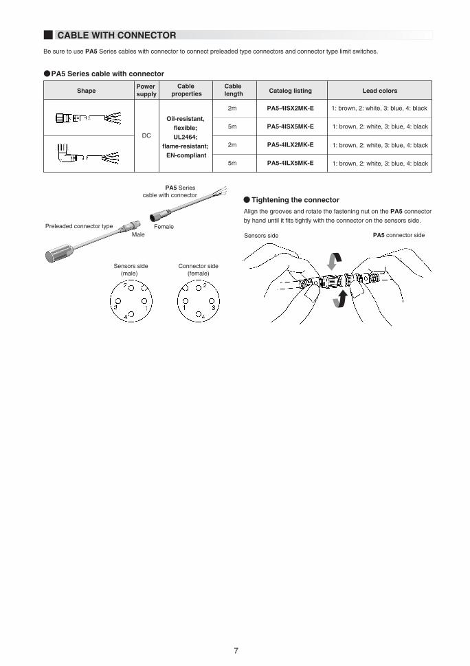
Be sure to use PA5 Series cables with connector to connect preleaded type connectors and connector type limit switches.
PA5 Series cable with connector
Preleaded connector type FemaleMale
CABLE WITH CONNECTOR
Align the grooves and rotate the fastening nut on the PA5 connector
by hand until it fits tightly with the connector on the sensors side.
Sensors side(male)
Connector side(female)
2m
5m
2m
5m
PA5-4ISX2MK-E
PA5-4ISX5MK-E
PA5-4ILX2MK-E
PA5-4ILX5MK-E
1: brown, 2: white, 3: blue, 4: black
1: brown, 2: white, 3: blue, 4: black
1: brown, 2: white, 3: blue, 4: black
1: brown, 2: white, 3: blue, 4: black
ShapePower supply
Cable length
Cable properties
Oil-resistant, flexible; UL2464;
flame-resistant; EN-compliant
Catalog listing Lead colors
DC
PA5 Series cable with connector
Tightening the connector
Sensors side PA5 connector side

1 28
PRECAUTIONS FOR USE
*The table shows the allowable tightening torque when toothed washers (provided) are used.
Shaded areas indicate surrounding metal other than the target object.
A: Distance from sensing face of proximity sensor to mounting surface
B: Distance from surface of iron plate to sensing face of proximity sensor.
Dimensions in parentheses apply if a hexagonal nut is attached to the front.
C: Distance from surface of iron plate to center of proximity switch when A=0
When mounting proximity sensors either parallel to or facing each
other, mutual interference may cause the sensor to malfunction.
Maintain at least the distances indicated in the figures below.
10
0
0
30.0
70.0
150.0
20.0— —
Length A (mm)
Catalog listingMax. tightening
torque (N·m)
2.5(15.5)
3.5(16.5)
6.5(10.0)
9.0
13.5
22.5
12
24
45
A(mm) B(mm) C(mm)Catalog listing
25
40
90
25
50
110
The voltage drop of these FL7M sensors is 5V. Pay attention to
this voltage drop when using a relay load. (With 12Vdc relays,
switching is not possible.)
After the power is turned ON, it takes at most 40ms until the
proximity sensor is ready for sensing. If the load and the proximity
sensor use different power supplies, be sure to turn the proximity
sensor ON before turning the load ON.
A minimal current flows as leakage current for operating the circuits
even when the proximity sensor is OFF. Keep this in mind when
turning off connected loads.
The minimum bend radius (R) of the cable is 3 times the cable
diameter. Take care not to bend the cable beyond this radius.
Also, do not excessively bend the cable within 30mm of the cable
lead-in port
Facing each other
Parallel
Load
A(mm) B(mm)Catalog listing
When connect ing two or more proximity sensors in series,
erroneous output (1 to 3ms) may occur without the rated current
being supplied to each of the sensors. For this reason, series
connection of proximity sensors is not recommended. However, if
proximity sensors must be connected in series, a resistor of 10kΩ
must be put in parallel to each of the sensors. Note that the
maximum leakage current in a series connection will be 3.5mA.
Operation lag also will occur, resulting in increased voltage drop,
and the operation indicator lamp will not light.
Operation lag =
40ms x (No. of sensors in series - 1)
Voltage drop =
Voltage drop of single sensor x
No. of sensors in series
If two or more proximity sensors are connected in parallel, total
leakage current increases according to the following formula, and
may result in the load not turning OFF. (Leakage current =
Leakage current of single sensor x No. of sensors in parallel)
When two or more sensors in parallel turn ON, one (or more) of
LoadFL7M-4 6FL7M-8 6FL7M-15 6
FL7M-4 6FL7M-8 6FL7M-15 6
FL7M-4 6FL7M-8 6FL7M-15 6
A B
C C
A
B
A
B
1. Mounting
2. Influence of surrounding metal
3. Mutual interference prevention
4. Cautions for series or parallel connection
5. Relay loads
6. Operation upon power ON
7. Influence of leakage current
8. Minimum cable bend radius (R)
Parallel connection (OR switching circuit)4.2
Series connection (AND switching circuit)4.1
Metal other than the target object surrounding the sensor may
influence operating characteristics. Leave space between the sensor
and surrounding metal as shown below.
The allowable tightening torque varies according to the distance
from the sensing face.