Embed Size (px)
Citation preview
DCS800
DCS800 Winder Description Indirect Tension Control Package
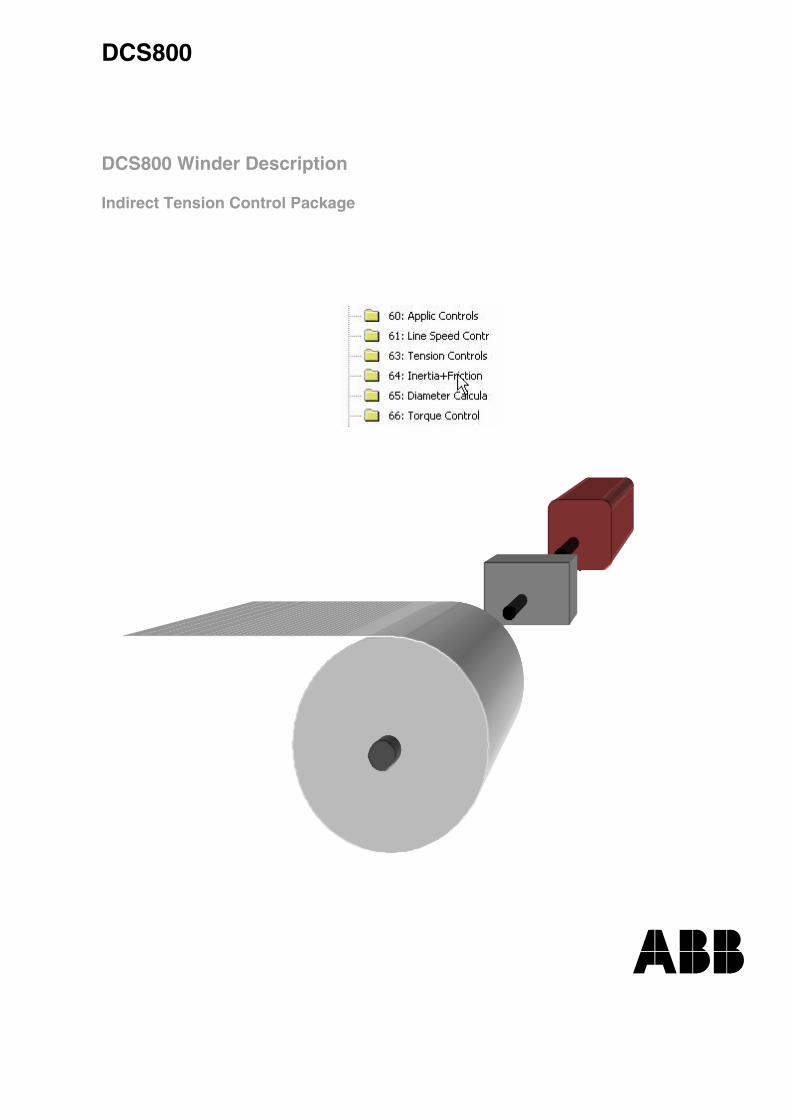
DCS800 Drive Manuals All the documents available for the drive system DCS800 are listed below:
Language Public. number E D I ES F CN
DCS800 Quick Guide 3ADW000191 x p p p p DCS800 Tools & Documentation CD 3ADW000211 x DCS800 Converter module
Flyer DCS800 3ADW000190 x x p x p p Technical Catalogue DCS800 3ADW000192 x x x x p x Hardware Manual DCS800 3ADW000194 x x p p p p Firmware Manual DCS800 3ADW000193 x p p p p p Installation according to EMC 3ADW000032 x Technical Guide 3ADW000163 x Service Manual DCS800 3ADW000195 x p Planning and Start-up for12-Pulse converters 3ADW000196 p CMA-2 Board 3ADW000136 p Flyer Hard - Parallel 3ADW000153 p
Drive Tools
DriveWindow 2.x - User's Manual 3BFE64560981 x DriveOPC 2.x - User's Manual 3BFE00073846 x Optical DDCS Communication Link 3AFE63988235 x DDCS Branching Units - User´s Manual 3BFE64285513 x
DCS800 Applications
PLC Programming with CoDeSys CoDeSys_V23 x x x 61131 DCS800 target +tool description - Application Program 3ADW000199 x Winding with the DCS 800XXXXX 3ADW000058 Winder application description 3ADW000253 x Flyer magnetic application Magnetic application description
DCS800-E Panel Solution
Flyer DCS800-E Panel solution 3ADW000210 x Hardware Manual DCS800-E 3ADW000224 x
DCS800-A Enclosed Converters
Flyer DCS800-A 3ADW000213 x Technical Catalogue DCS800-A 3ADW000198 x p Installation of DCS800-A 3ADW000091 p p
DCS800-R Rebuild System
Flyer DCS800-R 3ADW000007 x x DCS800-R Manual 3ADW000197 x DCS500/DCS600 Size A5...A7, C2b, C3 and C4 Upgrade Kits 3ADW000256 x
Extension Modules
RAIO-01 Analogue IO Extension 3AFE64484567 x RDIO-01 Digital IO Extension 3AFE64485733 x AIMA R-slot extension 3AFE64661442 x
Serial Communication
Drive specific serial communication NETA Remote diagnostic interface 3AFE64605062 x Fieldbus Adapter with DC Drives RPBA- (PROFIBUS) 3AFE64504215 x Fieldbus Adapter with DC Drives RCAN-02 (CANopen) Fieldbus Adapter with DC Drives RCNA-01 (ControlNet) 3AFE64506005 x Fieldbus Adapter with DC Drives RDNA- (DeviceNet) 3AFE64504223 x Fieldbus Adapter with DC Drives RMBA (MODBUS) 3AFE64498851 x Fieldbus Adapter with DC Drives RETA (Ethernet) 3AFE64539736 x
x -> existing p -> planned Status 09.2007 DCS800 Drive Manuals-List_e.doc
3
Table of contents
3ADW000308R0201 DCS800 Winder Tens ctrl e b
Table of contents
DCS800 Drive Manuals.............................................................................................................. 02
Table of contents............................................................................................................................... 1 H3
DCS800 Winder.................................................................................................................................. 2 H5 Indirect tension control ............................................................................................................... 3 H5
Winder formulas and calculation..................................................................................................... 4 H6 Diameter .................................................................................................................................... 5 H6 Tension ...................................................................................................................................... 6 H7 Acceleration Torque................................................................................................................... 7 H8 Losses........................................................................................................................................ 8 H8 Winder motor ............................................................................................................................. 9 H9
Winder structure.............................................................................................................................. 1 0 H10 Interface DCS800 firmware and winder application ................................................................. 1 1 H10
Signal and Parameter list ............................................................................................................... 1 2 H16 Group 7......................................................................................................................... 1 3 H17 Group 8......................................................................................................................... 1 4 H18 Group 60....................................................................................................................... 1 5 H18 Group 61....................................................................................................................... 1 6 H21 Group 63....................................................................................................................... 1 7 H25 Group 64....................................................................................................................... 1 8 H27 Group 65....................................................................................................................... 1 9 H31 Group 66....................................................................................................................... 2 0 H34 Appendix ...................................................................................................................... 2 1 H35 Appendix ...................................................................................................................... 2 2 H35
Safety instructions .......................................................................................................................... 2 3 H36 What this chapter contains....................................................................................................... 2 4 H36 To which products this chapter applies.................................................................................... 2 5 H36 Usage of warnings and notes .................................................................................................. 2 6 H36 Installation and maintenance work........................................................................................... 2 7 H37
Grounding..................................................................................................................... 2 8 H38 Mechanical installation............................................................................................................. 2 9 H40 Operation ................................................................................................................................. 3 0 H41
Commissioning ............................................................................................................................... 3 1 H43 Guidance.................................................................................................................................. 3 2 H43 Control Bits (Example) ............................................................................................................ 3 3 H50
Appendix A - Application handling................................................................................................ 3 4 H51 Identification............................................................................................................................. 3 5 H51 Installation................................................................................................................................ 3 6 H51

4
Table of contents
3ADW000308R0201 DCS800 Winder Tens ctrl e b
Enable / disable application ..................................................................................................... 3 7 H52
5
DCS800 Winder
3ADW000308R0201 DCS800 Winder Tens ctrl e b
DCS800 Winder Winder drives can operate in
• velocity control • indirect tension control • direct tension control, equipped with a load cell • dancer control, equipped with a dancer roll
Winder control systems, except velocity control, needs the following conditions:
• The lead roll must be in velocity control • The velocity signal for the winder drive comes from the lead roll or is only a reference signal • Winder ratio should be lower than 1:12 • Quality of winding will be defined by the exactness of the calculation
This description contains the indirect tension control, which is also called as indirect torque control.
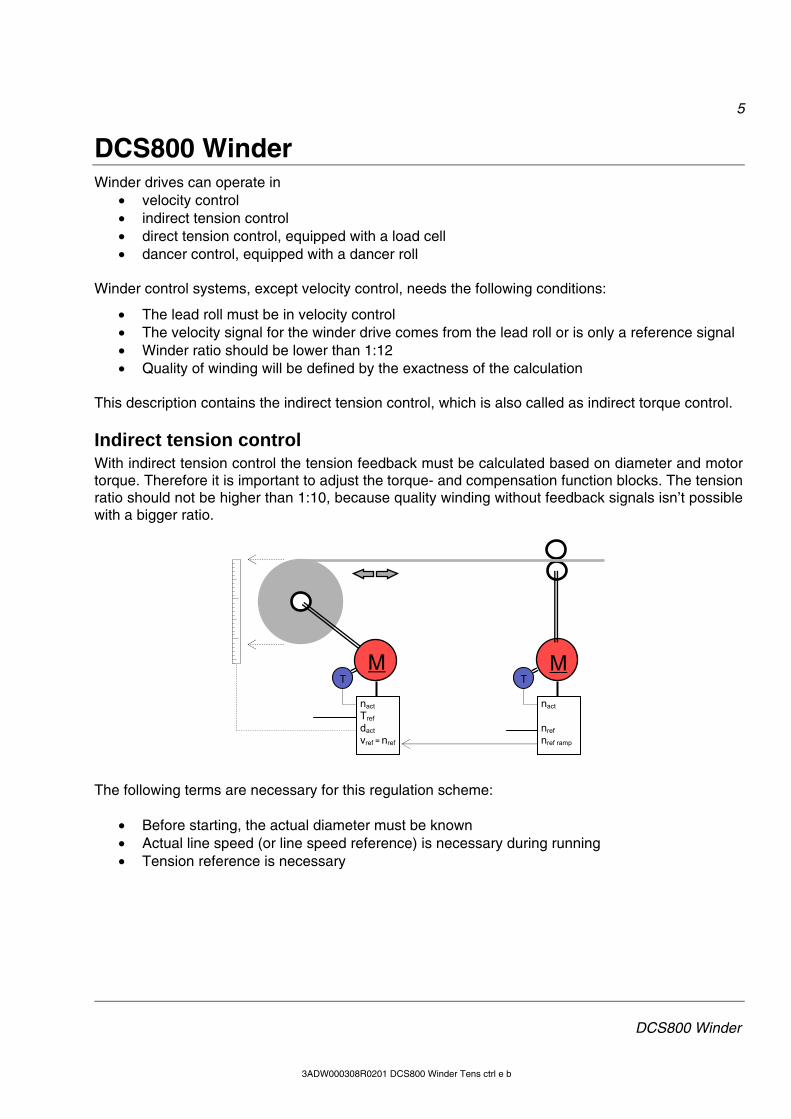
Indirect tension control With indirect tension control the tension feedback must be calculated based on diameter and motor torque. Therefore it is important to adjust the torque- and compensation function blocks. The tension ratio should not be higher than 1:10, because quality winding without feedback signals isn’t possible with a bigger ratio.
The following terms are necessary for this regulation scheme:
• Before starting, the actual diameter must be known • Actual line speed (or line speed reference) is necessary during running • Tension reference is necessary
M MT
nact Tref dact vref = nref
T
nact ... nref nref ramp
6
Winder formulars and calculation
3ADW000308R0101 DCS800 Winder Tens ctrl e a 3ADW000308R0201 DCS800 Winder Tens ctrl e b
Winder formulas and calculation With DCS800 Winder Library it is possible to design winder applications using CoDeSys. For wind-ers it is important that the following conditions are existing:
• The line speed (velocity) of the web is constant • The material tension is constant (oscillating isn’t allowed) • Motor speed must be adapted to actual diameter • Motor torque depends on the actual diameter
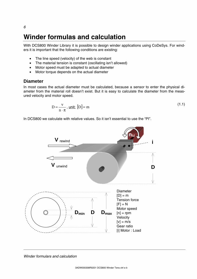
Diameter In most cases the actual diameter must be calculated, because a sensor to enter the physical di-ameter from the material roll doesn’t exist. But it is easy to calculate the diameter from the meas-ured velocity and motor speed.
π⋅=
nvD , unit: [ ] mD =
(1.1)
In DCS800 we calculate with relative values. So it isn’t essential to use the “PI”.
Diameter [D] = m Tension force [F] = N Motor speed [n] = rpm
Velocity [v] = m/s
Gear ratio [i] Motor : Load
V rewind
V unwind D
i nM
Dmin D Dmax
7
Winder formulars and calculation
3ADW000308R0201 DCS800 Winder Tens ctrl e b
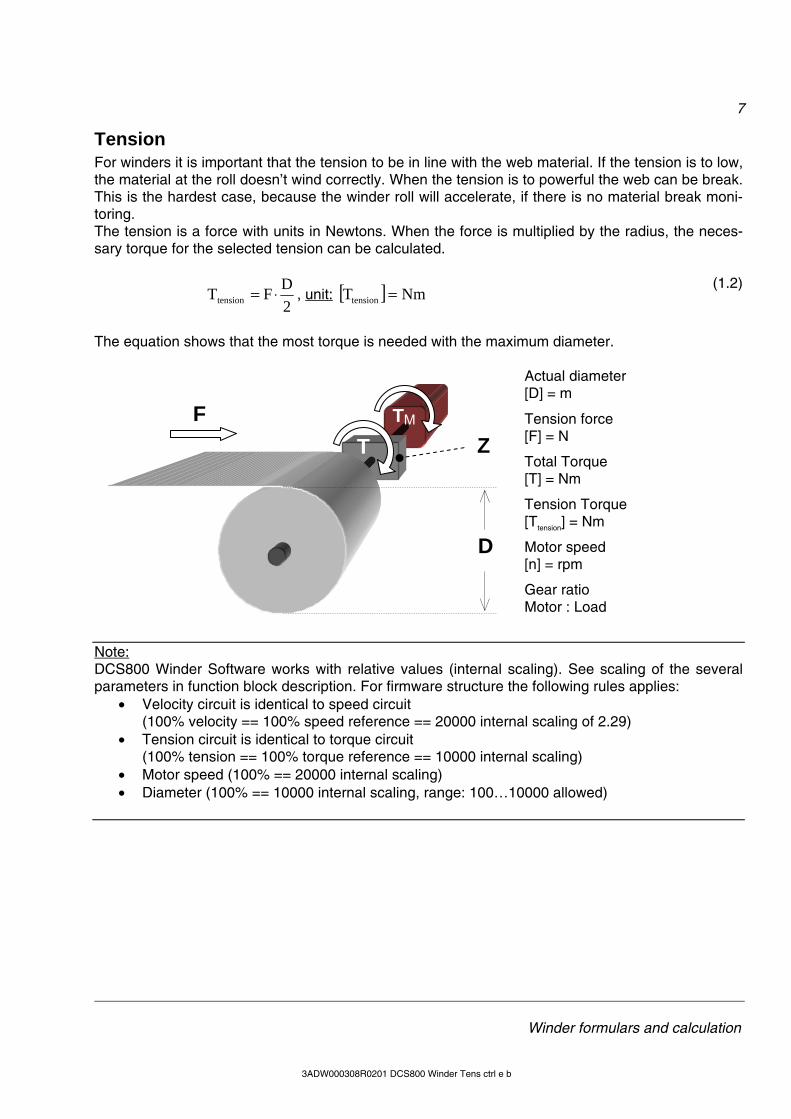
Tension For winders it is important that the tension to be in line with the web material. If the tension is to low, the material at the roll doesn’t wind correctly. When the tension is to powerful the web can be break. This is the hardest case, because the winder roll will accelerate, if there is no material break moni-toring. The tension is a force with units in Newtons. When the force is multiplied by the radius, the neces-sary torque for the selected tension can be calculated.
2DFTtension ⋅= , unit: [ ] NmTtension =
(1.2)
The equation shows that the most torque is needed with the maximum diameter.
Actual diameter [D] = m
Tension force [F] = N
Total Torque [T] = Nm
Tension Torque [Ttension] = Nm
Motor speed [n] = rpm
Gear ratio Motor : Load
Note: DCS800 Winder Software works with relative values (internal scaling). See scaling of the several parameters in function block description. For firmware structure the following rules applies:
• Velocity circuit is identical to speed circuit (100% velocity == 100% speed reference == 20000 internal scaling of 2.29)
• Tension circuit is identical to torque circuit (100% tension == 100% torque reference == 10000 internal scaling)
• Motor speed (100% == 20000 internal scaling) • Diameter (100% == 10000 internal scaling, range: 100…10000 allowed)
F
D
ZTM
T
8
Winder formulars and calculation
3ADW000308R0101 DCS800 Winder Tens ctrl e a 3ADW000308R0201 DCS800 Winder Tens ctrl e b
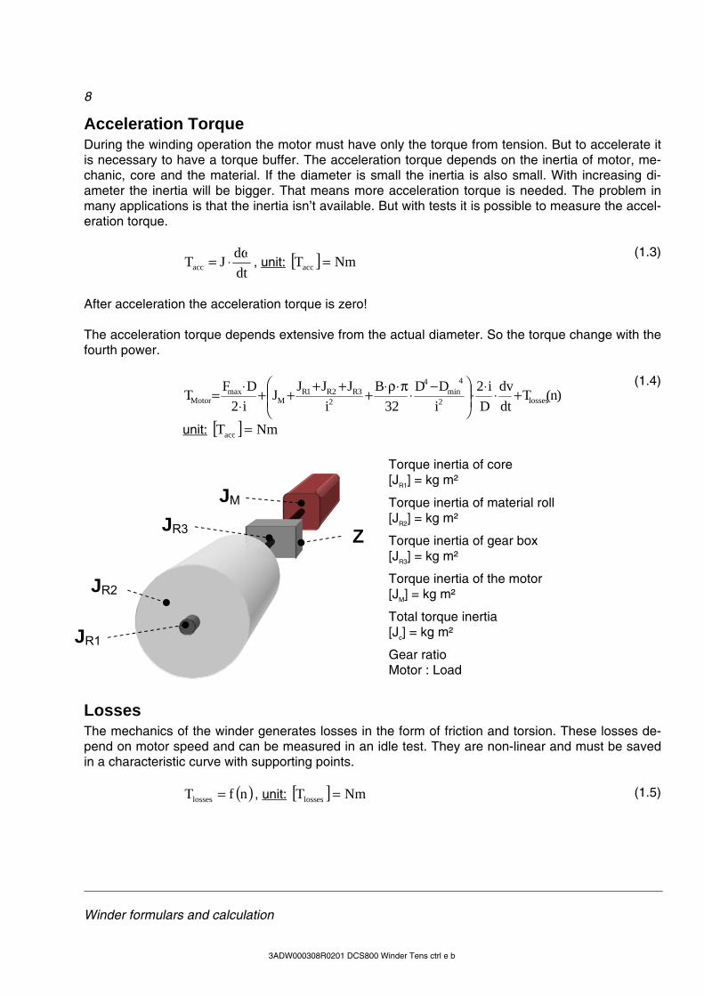
Acceleration Torque During the winding operation the motor must have only the torque from tension. But to accelerate it is necessary to have a torque buffer. The acceleration torque depends on the inertia of motor, me-chanic, core and the material. If the diameter is small the inertia is also small. With increasing di-ameter the inertia will be bigger. That means more acceleration torque is needed. The problem in many applications is that the inertia isn’t available. But with tests it is possible to measure the accel-eration torque.
dtdJTacc
ω⋅= , unit: [ ] NmTacc = (1.3)
After acceleration the acceleration torque is zero! The acceleration torque depends extensive from the actual diameter. So the torque change with the fourth power.
)n(Tdtdv
Di2
iDD
32B
iJJJJ
i2DFT losses2
4min
4
23R2R1R
Mmax
Motor +⋅⋅⋅⎟⎟⎠
⎞⎜⎜⎝
⎛ −⋅π⋅ρ⋅+++++⋅⋅=
unit: [ ] NmTacc =
(1.4)
Torque inertia of core [JR1] = kg m²
Torque inertia of material roll [JR2] = kg m²
Torque inertia of gear box [JR3] = kg m²
Torque inertia of the motor [JM] = kg m²
Total torque inertia [Jc] = kg m²
Gear ratio Motor : Load
Losses The mechanics of the winder generates losses in the form of friction and torsion. These losses de-pend on motor speed and can be measured in an idle test. They are non-linear and must be saved in a characteristic curve with supporting points.
( )nfTlosses = , unit: [ ] NmTlosses = (1.5)
ZJR3
JR1
JR2
JM
9
Winder formulars and calculation
3ADW000308R0201 DCS800 Winder Tens ctrl e b
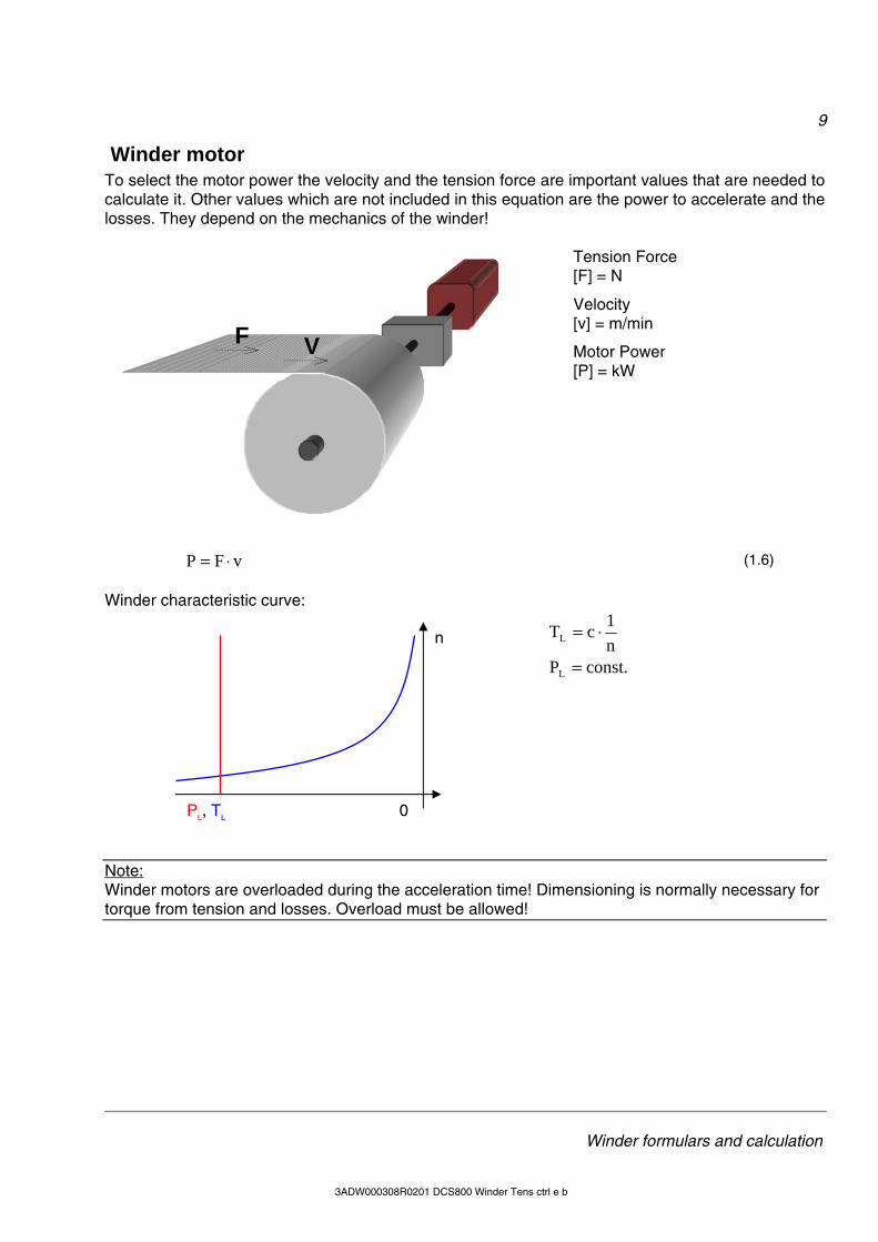
Winder motor To select the motor power the velocity and the tension force are important values that are needed to calculate it. Other values which are not included in this equation are the power to accelerate and the losses. They depend on the mechanics of the winder!
Tension Force [F] = N
Velocity [v] = m/min
Motor Power [P] = kW
vFP ⋅= (1.6)
Winder characteristic curve:
n1cTL ⋅=
.constPL =
Note: Winder motors are overloaded during the acceleration time! Dimensioning is normally necessary for torque from tension and losses. Overload must be allowed!
V F
0 PL, TL
n
10
Winder structure
3ADW000308R0101 DCS800 Winder Tens ctrl e a 3ADW000308R0201 DCS800 Winder Tens ctrl e b
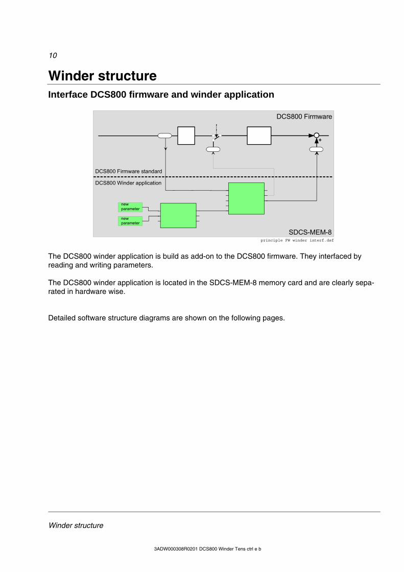
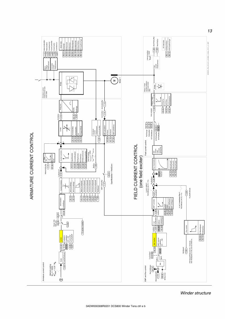
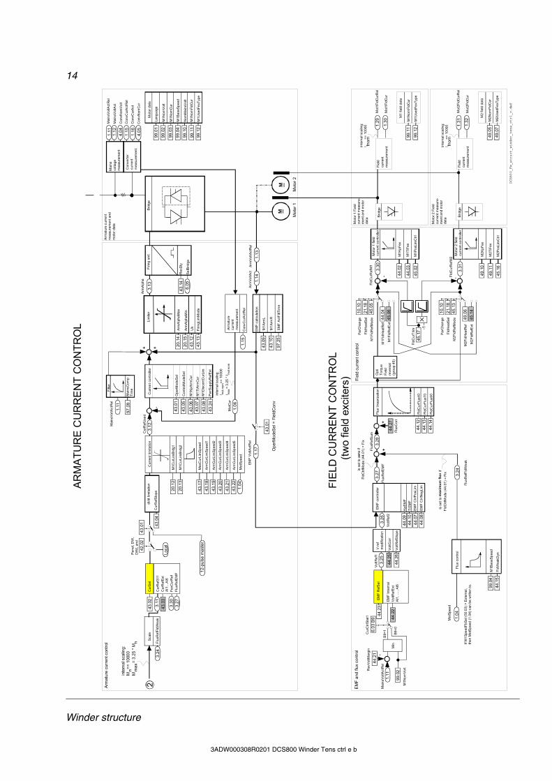
Winder structure Interface DCS800 firmware and winder application
DCS800 Firmware standard
new parameter
DCS800 Winder application
new parameter
+
DCS800 Firmware
SDCS-MEM-8principle FW winder interf.dsf
The DCS800 winder application is build as add-on to the DCS800 firmware. They interfaced by reading and writing parameters. The DCS800 winder application is located in the SDCS-MEM-8 memory card and are clearly sepa-rated in hardware wise. Detailed software structure diagrams are shown on the following pages.
11
Winder structure
3ADW000308R0201 DCS800 Winder Tens ctrl e b
11.1
2
11.0
6
AC
W B
6
Pul
se e
ncod
er 1
Ana
log
tach
o
EMF
M1B
aseS
peed
M1N
omVo
lt
Ref
1Sel
0 = open
SpeedRefExt1
2.17SpeedRefUsed
2.18
23.1
5
ACW
1 B
4
M1E
ncM
easM
ode
M1E
ncPu
lseN
o
M1T
achA
djus
t
M1T
acho
Vol
t100
0
Spee
dAct
Enc
Dire
ctSp
eedR
efSpee
dRef
3Sp
eedR
ef4
Dro
opR
ate
24.0
2
Torq
AccC
ompR
ef
Acce
lera
tion
com
pens
atio
n
AccC
ompD
erTi
me
AccC
ompF
iltTi
me
24.1
4
24.1
5
Spee
dCor
r23
.04
2.02
Torq
Ref
1
Torq
Min
All
Hol
dSpe
edC
trl
Spee
dSte
p
AC
W B
8
D23
.10
Torq
Ref
2
BalS
peed
Ctrl
BalR
ef
PI
24.1
1
PID
-con
trolle
r
Torq
Der
Ref
Torq
Prop
Ref
Lim
iter
Torq
Max
SPC
Torq
Min
SPC
Torq
Inte
gRef
2.08
2.20
KpSV
alM
inS
peed
TiSV
alM
inS
peed
Der
ivTi
me
Der
ivFi
ltTim
e
Torq
Ref
2 (2
.09)
24.1
7
24.1
024
.09
24.0
624
.05
24.0
4
24.0
3Kp
S
KpSM
in
KpSW
eakp
KpSV
alM
inSp
eed
KpST
iSM
inS
peed
KpSW
eakp
FiltT
ime
TiS
TiSI
nitV
alue
KpST
iSM
inS
peed
KpS
TiS
24.1
324
.12
24.2
024
.19
24.1
8
p-pa
rt, i-
part
TiSV
alM
inSp
eed
spee
dKp
STiS
Max
Spee
d
KpST
iSM
axSp
eed
p-pa
rtKp
S
KpSM
in
KpSW
eakp
KpSV
alM
inS
peed
TiSV
alM
inS
peed
Der
ivTi
me
Der
ivFi
ltTim
e
Torq
Ref
2 (2
.09)
KpS
KpSM
in
KpSW
eakp
KpSW
eakp
FiltT
ime
TiS
TiSI
nitV
alue
KpST
iSM
inS
peed
KpS
TiS
p-pa
rt, i-
part
spee
d
KpST
iSM
axSp
eed
p-pa
rtKp
S
KpSM
in
KpSW
eakp
+-
Panel, DW, DWL
20.0
120
.02
Spee
dRef
2301
AuxS
peed
Ref
AI1…
AI6
Fixe
dSpe
ed1
Fixe
dSpe
ed2
Mot
Pot
AuxR
ef-A
I1re
serv
edM
inAI
2AI4
Max
AI2
AI4
Ref
1Mux
Ope
nC
lose
DI1
…D
I8M
CW
Bit1
1…B
it15
ACW
Bit1
2…B
it15
2.30
Ref
2Sel
0 =
open
Spee
dRef
Ext2
Spee
dRef
2301
AuxS
peed
Ref
AI1…
AI6
Fixe
dSpe
ed1
Fixe
dSpe
ed2
Mot
Pot
AI2-
AI3
AI2+
AI3
AI2*
AI3
Min
AI2A
I4M
axA
I2AI
4
Ref
1Mux
Inve
rt110
2O
pen
Clo
seD
I1, …
, DI8
MC
W B
it11…
Bit1
5AC
W B
it12…
Bit
15
2.16
0000
2.01
Hol
d
Ram
p
Ram
pTim
eSca
le
Jog
Ram
p
JogD
ecTi
me
JogA
ccTi
me
22.1
2
22.1
3
23.0
2
23.0
3
2.32
Fixe
dSpe
ed1
Fixe
dSpe
ed2
Spee
dRef
2
E S
topR
amp
Shap
eTim
e
VarS
lope
Rat
e
BalR
ampO
ut
Ram
pByp
ass
BalR
ampR
ef
dv_d
t
Acc
/Dec
/Sha
peSp
eed
Ram
pOut
Spee
dAct
EMF
Spee
dAct
Tach
inte
rnal
sca
ling:
Spe
edS
cale
Act
(2.2
9) =
= 20
000
Mot
Spee
d
1 se
cond
Filte
r
Mot
Spee
dFilt
Win
derS
cale
Proc
Spee
d
Spee
dErrF
ilt
Win
dow
Intg
On
Win
Wid
thPo
s
Win
Wid
thN
eg
Win
dow
Ctrl
Mod
e
Win
dow
con
trol
2.03
Spee
dErrN
eg
23.0
6
-1
-
23.1
2
23.0
7
23.0
8
23.0
9
Spe
ed m
easu
rem
ent
Exte
rnal
M1S
peed
FbS
el
+
20.0
2
20.0
1
50.0
6
Filte
r
Spee
dFilt
Tim
e
AccT
ime1
Dec
Tim
e1
Torq
Max
All
2.19
-
Torq
ue s
elec
tor =
Add
-
Spe
ed re
fere
nce
sele
ctio
nS
peed
refe
renc
e se
lect
ion
Spe
ed ra
mp
Spe
ed a
ctua
l sel
ectio
nS
peed
act
ual s
elec
tion
Spe
ed c
ontro
ller
Spe
ed c
ontro
ller
SPEE
D R
EFE
RE
NC
E C
HAI
NSP
EED
CO
NTR
OL
2.31
Loca
l
AC
WB
2
MC
W B
4
MC
W B
6M
CW
B5
22.0
3
22.0
4
22.0
5
22.0
7
22.0
8
22.0
122
.02
AC
WB
3
23.0
123
.13
23.0
223
.03
23.0
123
.13
23.0
223
.03
Lim
iter
M1S
peed
Min
M1S
peed
Max
Lim
iter
M1S
peed
Max
M1S
peed
Min
+
2.07
2.05
2.04
2.06
20.0
7
20.0
8
2.09
50.0
4
50.0
2
99.0
299
.04
50.1
2
50.1
3
1.03
1.02
1.05
50.0
3
1.04
50.1
7
1.011.
41
Filte
r
AI1D
irect
+AI
2Dire
ct+
+
11.0
3
11.0
2
10.0
2D
irect
ion
-1
Jog2
(10.
18)
Jog1
(10.
17)
AC
W2
B10
MC
W B
8, B
9
24.1
3
2.19
24.1
3
Sig
nal
Par
amet
er
Par
amet
er is
usu
ally
writ
ten
to b
y Ad
aptiv
e P
rogr
am,
appl
icat
ion
prog
ram
or o
verr
idin
g co
ntro
lA
ttent
ion:
Th
e fir
mw
are
stru
ctur
e di
agra
ms
show
the
stan
dard
firm
war
e
Lege
nd
Pul
se e
ncod
er 2
Enc2
Mea
sMod
e
Enc2
Pul
seN
o50
.19
50.1
8
Spee
dAct
Enc2
1.42
Enc2
Dire
ct+
Enco
der2
23.0
5
DCS800_Fw_struct_winder_tens_ctrl_c.dsf
Adap
tGai
n
KpD
iaM
inTn
Dia
Min
KpD
iaM
ax
KpO
ut
TnD
iaM
axKp
Win
Mod
ef (
Cal
cDia
Act)Tn
Out
24.0
9
24.0
3
20.0
2
20.0
1
Dia
Cal
c
In1
Vel
oIn
2 N
act
Min
Cor
eDia
Tram
pWD
irTr
ampW
cDir
Rel
Vel
oLev
Rel
Spe
edLe
v
SelC
mdD
iaIn
itIn
it va
lue
Cal
cDia
Act
Win
Sca
le
Lim
Min
Lim
Max
-->
Velo
city
con
trol
--> V
ELO
CIT
Y C
ON
TRO
L
SelA
ctIit
2
SelD
iaIn
it1D
iaIn
it1AI
1...A
I6D
iaIn
it2 SelV
elR
ef
Velo
Ref
AI1.
..AI6
Enco
der 2
VelR
efIN Ve
loS
cale
Velo
Jog1
Velo
Jog2
SelJ
og1
SelJ
og2
Velo
WiP
rese
tScal
edV
elR
efO
ut
Win
Pos
Win
Neg
61.0
261
.01
61.0
361
.06
61.0
761
.08
61.0
961
.12
65.0
165
.04
65.0
565
.06
65.0
765
.08
65.2
0
61.2
0
65.1
265
.10
65.0
9
65.1
1
61.1
461
.15
61.1
661
.17
61.1
8
SpdF
iltTi
me
f (C
alcD
iaAc
t)
61.1
3
12
Winder structure
3ADW000308R0101 DCS800 Winder Tens ctrl e a 3ADW000308R0201 DCS800 Winder Tens ctrl e b
20.1
9
20.1
3M
1Cur
Lim
Brdg
2
Min
Torq
Use
dMax
Sel
Torq
Max
20.0
5AI
1, …
, AI6
Torq
Use
dMax
Torq
Use
dMin
Lim
6
6
Torq
Lim
Act
Torq
Ref
A25
01AI
1…AI
6
Torq
Ref
A S
el
+ +
0 01
2 3 45
Torq
ue s
elec
tor
Min
3
Max
4
Torq
Ref
Ext
2.24
Torq
Gen
Max
Torq
Ram
pUp
Torq
Ram
pDow
n
Torq
ue ra
mp
Lim
iter
Torq
Max
Tref
Torq
Min
Tref
Load
Com
p
Torq
ue li
mite
r
Torq
Max
All
Torq
Min
All
Gea
r bac
klas
h co
mpe
nsat
ion
Torq
Max
All
Torq
Min
All
26.0
1To
rqSe
l
25.0
1
Torq
Ref
4
25.0
2
Filte
r
Torq
Ref
A F
TC
25.0
3
Load
Shar
e
Torq
Ref
B
Add
5
Spee
d 1
Torq
ue 2
Torq
Ref
3G
earS
tartT
orq
Gea
rTor
qTim
e
Gea
rTor
qRam
p
Torq
Use
dMin
Sel
Torq
Min
20.0
6AI
1, …
, AI6
Neg
ate
2.23
=
2.22
* (-
1)
M1C
urLi
mBr
dg1
Flux
Ref
FldW
eak
Max
Torq
Ref
2
Torq
Ref
1
Not
Use
dD
I1, …
, DI1
1M
CW
Bit
11, …
, MC
W B
it15
ACW
Bit
12, …
, AC
W B
it 15
Torq
Mux
Torq
Sel2
601
(0…
6)Sp
eed/
Torq
(1 o
r 2)
Spee
d/M
in (1
or 3
)Sp
eed/
Max
(1 o
r 4)
Spee
d/Li
mit
(1 o
r 6)
Torq
Mux
Mod
e
+
+
Torq
Cor
r
Torq
Ref
Use
d
Not
Use
dAI
1, …
, AI6
Torq
Cor
rect
+
Torq
ue re
fere
nce
and
torq
ue s
elec
tion
Torq
ue li
mita
tion
TOR
QU
E C
ON
TRO
L C
HAI
N
25.0
4
25.0
5
25.0
6
20.0
9
20.1
0
2.19
2.20
2.09
2.08
2.10
26.0
2
20.0
5
20.1
2
3.24
2.11
26.0
8
26.0
9
26.1
0
2.22
20.2
2
2.19
2.20
2.26 2.14
2.13
20.0
6
2.23
97.0
1Ty
peC
ode=
2-Q
0%
25.1
0
26.0
526
.04
26.0
1Pa
nel,
DW
, DW
L an
dTo
rqR
ef2
2.09
20.1
8
26.1
5
-1
Loca
l
DCS800_Fw_struct_winder_tens_ctrl_c.dsf
SelT
ensR
ef
Tens
Ref
AI1.
..AI6
63.0
263
.01
Tens
Ref Te
Ref
Out
Tens
Ref
TapT
ens
TapD
iaTe
Ref
Hol
dSe
lTeR
efH
ldTe
Ref
Min
63.0
363
.05
63.0
663
.07
63.0
8
63.2
0To
rqS
cale
In1
Torq
Scal
eOut
Torq
Scal
e
Cal
cDia
Act
66.0
3
AccF
iltAc
cFilt
Out
AccF
iltIn
AccF
iltAc
cTD
AccM
ulAc
cDiv
64.0
364
.04
64.0
564
.06
64.4
0Ac
cTor
q AccT
qOut
AccF
iltO
utAc
cTqZ
eroL
evAc
cMec
PosS
caAc
cMec
Neg
Sca
AccC
oiPo
sSca
AccC
oiN
egS
caAc
cCoi
Wid
thC
alcD
iaAc
t
64.1
264
.13
64.1
464
.15
64.1
6
64.4
3
64.1
7
Torq
Com
p
TrqC
ompO
ut
TqC
pSpI
nTq
CpS
p0Tq
CpT
q0Tq
CpS
p...
TqC
pTq.
..Tq
CpS
p6Tq
CpT
q6Tq
CpD
iaTq
CpA
dd
64.2
064
.21
64. .
..64
. ...
64.3
2
64.4
6
64.3
364
.34
SelD
eriIn
Der
In A
I1...
AI6
Spec
ial
Extra
64.0
164
.02
61.2
02.
32
1.04
64.1
9na
ct
13
Winder structure
3ADW000308R0201 DCS800 Winder Tens ctrl e b
ParC
hang
e
M1F
ldH
eatR
ef
FldH
eatS
el
M1F
ldR
efM
ode
Fiel
dcu
rren
tm
easu
rem
ent
Mot
1Fld
Cur
Rel
Mot
1Fld
Cur
1.29
1.30
Mot
or 1
fiel
d cu
rren
t con
trolle
r
M1K
pFex
M1T
iFex
M1F
ldR
efE
xt
FldC
urR
efM
1
inte
rnal
sca
ling:
I fnom
== 1
0000
M1P
osLi
mC
trl
Fiel
d cu
rren
t con
trol
Mot
or 1
Fie
ld
curr
ent m
easu
re-
men
t and
mot
orda
ta
44.0
445
.0610
.10
21.1
845
.05
44.0
2
44.0
3
3.30
45.0
2
M1N
omFl
dCur
M1
field
dat
a
99.1
299
.11
M1U
sedF
exTy
pe
Fiel
dre
vers
al(g
roup
45)
Opt
iTo
rque
Brid
ge
44.0
944
.10
44.0
744
.08
is s
et to
max
imum
flux
ifFl
dCtrl
Mod
e (4
4.01
) = F
ix
43.1
743
.18
43.1
943
.20
43.2
143
.22
1.04
Ope
rMod
eSel
M1A
rmL
M1A
rmR
SelB
ridge
6.05
M1N
omFl
dCur
M1U
sedF
exTy
pe
M1B
aseS
peed
If M
1Spe
edFb
Sel (
50.0
3) =
Ext
erna
l,th
en M
otS
peed
(1.0
4) c
an b
e w
ritte
n to
.
Ope
rMod
eSel
= F
ield
Con
v
PwrS
uppl
yRef
Ext
Cur
Ref
Slop
e
di/d
t lim
itatio
n
20.1
2M
1Cur
Lim
Brdg
1
20.1
3M
1Cur
Lim
Brdg
2
Cur
Ref
Use
dC
urre
nt c
ontro
ller
Con
trolM
odeS
el
M1K
pArm
Cur
M1T
iArm
Cur
M1D
isco
ntC
urLi
m
Mot
Cur
1.15
EMF-
calc
ulat
ion
Arm
Alph
a
Firin
g un
it
43.1
4R
evD
ly
M1N
omVo
lt
M1N
omC
ur
Mai
nsvo
ltage
mea
sure
men
t
Con
verte
rcu
rren
tm
easu
rem
ent.
Nom
Mai
nsV
olt
Mai
nsVo
ltAct
Rel
Mai
nsVo
ltAct
Con
vCur
Act
Rel
Con
vCur
Act
1.11
1.12
1.15
1.16
M
Mot
or 1
FldC
urFl
ux40
FldC
urFl
ux70
FldC
urFl
ux90
Flux
line
ariz
atio
n
EMF
Vol
tAct
Rel
1.17
EMF
cont
rolle
r
KpEM
FTi
EMF
Flux
con
trol
M1B
aseS
peed
Mot
Spee
d
inte
rnal
sca
ling:
Mn==
100
00M
max
= 3.
25 *
Mn
Flux
Ref
FldW
eak
3.24
Flux
Ref
Sum
Cur
Ctrl
Stat
1
Flux
Ref
EM
F
VoltC
orr
VoltR
efS
lope
V re
fm
odifi
catio
n
VoltR
ef2
FldW
eakD
yn
is s
et to
zer
oif
FldC
trlM
ode
(44.
01) =
Fix
EMF
Inte
rnal
VoltR
efE
xtAI
1, …
, AI6
EMF
Ref
Sel
EMF
Ctrl
Pos
Lim
EMF
Ctrl
Neg
Lim
97.0
9
Filte
rFi
lter
Mai
nsC
omp
Tim
e
Max
Cur
Lim
Spee
d
Mot
Spee
d
Arm
Cur
Lim
Spee
d1
Arm
Cur
Lim
Spee
d2
Arm
Cur
Lim
Spee
d3
Arm
Cur
Lim
Spee
d4
Arm
Cur
Lim
Spee
d5
Mai
nsVo
ltAct
Rel
Lang
uage
Mot
or d
ata
EMF
Act
FiltT
ime
44.2
5
44.2
6
Arm
atur
ecu
rren
tm
easu
rem
ent
Con
vCur
Act
Rel
Flux
Cor
r
-++
++
Arm
VoltA
ct
Arm
VoltA
ctR
el
Cur
rent
lim
itatio
nBr
idge
inte
rnal
sca
ling:
I mot
nom
== 1
0000
I max
= 3.
25 *
I mot
nom
FIEL
D C
UR
REN
T C
ON
TRO
L(o
ne fi
eld
exci
ter)
Mai
nsVo
ltAct
Rel
-
Rev
VoltM
argi
n Min
M1N
omVo
lt
B9=1 B9
=0
VoltR
ef1
Arm
atur
e cu
rren
t con
trol
EM
F an
d flu
x co
ntro
l
ARM
ATU
RE
CU
RR
ENT
CO
NTR
OL
Arm
atur
e cu
rrent
m
easu
rem
ent a
nd
mot
or d
ata
Con
vNom
Volt
4.04
Con
vNom
Cur
4.05
3.12
1.06
43.0
1
43.0
5
43.0
643
.07
43.0
843
.24
1.11
43.1
343
.12
20.1
520
.14
3.13
99.0
2
99.0
3
99.1
199
.12
99.0
499
.10
99.0
1
1.14
1.13
43.0
9
43.1
0
97.2
5
44.2
1
1.11
99.0
244
.22
3.25
1.04
99.0
444
.15
3.26
3.27
3.28
44.1
244
.13
44.1
4
44.2
7
43.0
4
43.0
1
Lim
iter
Arm
Alph
aMin
Arm
Alph
aMax
Uk
Firin
gLim
Mod
e
44.2
36.
03 B
9
Cur
Ref
311
Cur
Ref
Ext
AI1…
AI6
FexC
urR
efFl
uxR
efE
MF
Cur
Sel
Flux
Ref
FldW
eak
Scal
e
n
3.24
43.0
33.
11
43.0
2
3.30
3.27
12-p
ulse
mas
ter
42.0
2
Pane
l, D
W,
DW
L an
d
Loca
l
43.0
1
DCS800_Fw_struct_winder_tens_ctrl_c.dsf
14
Winder structure
3ADW000308R0101 DCS800 Winder Tens ctrl e a 3ADW000308R0201 DCS800 Winder Tens ctrl e b
44.0
944
.10
44.0
744
.08
is s
et to
max
imum
flux
ifFl
dCtrl
Mod
e (4
4.01
) = F
ix
ParC
hang
e
M1F
ldH
eatR
ef
FldH
eatS
el
If M
1Spe
edFb
Sel (
50.0
3) =
Ext
erna
l,th
en M
otS
peed
(1.0
4) c
an b
e w
ritte
n to
.
M1F
ldR
efM
ode
Fiel
dcu
rren
tm
easu
rem
ent
Mot
1Fld
Cur
Rel
Mot
1Fld
Cur
1.29
1.30
Mot
or 1
fiel
d cu
rren
t con
trolle
r
M1K
pFex
M1T
iFex
FldC
urFl
ux40
FldC
urFl
ux70
FldC
urFl
ux90
Flux
line
ariz
atio
nEM
F co
ntro
ller
KpEM
FTi
EMF
Flux
con
trol
M1B
aseS
peed
Mot
Spee
d
Flux
Ref
FldW
eak
3.24
Flux
Ref
Sum
Cur
Ctrl
Stat
1
Flux
Ref
EM
F
VoltC
orr
VoltR
efS
lope
V re
fm
odifi
catio
n
VoltR
ef2
FldW
eakD
yn
is s
et to
zer
oif
FldC
trlM
ode
(44.
01) =
Fix
EMF
Inte
rnal
VoltR
efE
xtAI
1, …
, AI6
EMF
Ref
Sel
EMF
Ctrl
Pos
Lim
EMF
Ctrl
Neg
Lim
44.2
5
44.2
6
M1F
ldR
efE
xt
Flux
Cor
r
FldC
urR
efM
1
++
inte
rnal
sca
ling:
I fnom
== 1
0000
M1P
osLi
mC
trl
Mai
nsVo
ltAct
Rel
-
Rev
VoltM
argi
n Min
M1N
omVo
lt
B9=
1
B9=0
VoltR
ef1
EM
F an
d flu
x co
ntro
lFi
eld
curr
ent c
ontro
lM
otor
1 F
ield
cu
rren
t mea
sure
-m
ent a
nd m
otor
data
44
.21
1.11
99.0
244
.22
3.25
1.04
99.0
444
.15
3.26
3.27
3.28
44.1
244
.13
44.1
4
44.0
445
.0610
.10
21.1
845
.05
44.0
2
44.0
3
3.30
45.0
2
44.2
7
M1N
omFl
dCur
M1
field
dat
a
99.1
2
99.1
1M
1Use
dFex
Type
44.2
36.
03 B
9
Fiel
dre
vers
al(g
roup
45)
Opt
iTo
rque
Brid
ge
43.1
743
.18
43.1
943
.20
43.2
143
.22
1.04
Ope
rMod
eSel
M1A
rmL
M1A
rmR
SelB
ridge
6.05
M1N
omFl
dCur
M1U
sedF
exTy
pe
M1B
aseS
peed
Ope
rMod
eSel
= F
ield
Con
v
PwrS
uppl
yRef
Ext
Cur
Ref
311
Cur
Ref
Ext
AI1…
AI6
FexC
urR
efFl
uxR
efE
MF
Cur
Sel
Flux
Ref
FldW
eak
Cur
Ref
Slop
e
di/d
t lim
itatio
nSc
ale
20.1
2M
1Cur
Lim
Brdg
1
20.1
3M
1Cur
Lim
Brdg
2
Cur
Ref
Use
dC
urre
nt c
ontro
ller
Con
trolM
odeS
el
M1K
pArm
Cur
M1T
iArm
Cur
M1D
isco
ntC
urLi
m
Mot
Cur
1.15
EMF-
calc
ulat
ion
Arm
Alph
a
Firin
g un
it
43.1
4R
evD
ly
M1N
omVo
lt
M1N
omC
ur
Mai
nsvo
ltage
mea
sure
men
t
Con
verte
rcu
rren
tm
easu
rem
ent.
Nom
Mai
nsV
olt
Mai
nsVo
ltAct
Rel
Mai
nsVo
ltAct
Con
vCur
Act
Rel
Con
vCur
Act
1.11
1.12
1.15
1.16
EMF
Vol
tAct
Rel
1.17
inte
rnal
sca
ling:
Mn==
100
00M
max
= 3.
25 *
Mn
97.0
9
Filte
rFi
lter
Mai
nsC
omp
Tim
e
Max
Cur
Lim
Spee
d
Mot
Spee
d
Arm
Cur
Lim
Spee
d1
Arm
Cur
Lim
Spee
d2
Arm
Cur
Lim
Spee
d3
Arm
Cur
Lim
Spee
d4
Arm
Cur
Lim
Spee
d5
Mai
nsVo
ltAct
Rel
Lang
uage
Mot
or d
ata
EMF
Act
FiltT
ime
Arm
atur
ecu
rren
tm
easu
rem
ent
Con
vCur
Act
Rel
-++
Arm
VoltA
ct
Arm
VoltA
ctR
el
Cur
rent
lim
itatio
nBr
idge
inte
rnal
sca
ling:
I mot
nom
== 1
0000
I max
= 3.
25 *
I mot
nom
Arm
atur
e cu
rren
t con
trol
Arm
atur
e cu
rrent
m
easu
rem
ent a
nd
mot
or d
ata
Con
vNom
Volt
4.04
Con
vNom
Cur
4.05
3.24
43.0
33.
11
3.12
1.06
43.0
1
43.0
5
43.0
643
.07
43.0
843
.24
1.11
43.1
343
.12
20.1
520
.14
3.13
99.0
2
99.0
3
99.1
199
.12
99.0
499
.10
99.0
1
1.14
1.13
43.0
9
43.1
0
97.2
5
43.0
2
3.30
3.27
12-p
ulse
mas
ter
43.0
4
43.0
1
Lim
iter
Arm
Alph
aMin
Arm
Alph
aMax
Uk
Firin
gLim
Mod
e
M
Mot
or 1
M
Mot
or 2
42.0
2
Pane
l, D
W,
DW
L an
d
Loca
l
43.0
1
FIEL
D C
UR
REN
T C
ON
TRO
L(tw
o fie
ld e
xcite
rs)
ARM
ATU
RE
CU
RR
ENT
CO
NTR
OL
ParC
hang
e
M2F
ldH
eatR
ef
FldH
eatS
el
M2F
ldR
efM
ode
Mot
or 2
fiel
d cu
rren
t con
trolle
r
M2K
pFex
M2T
iFex
M2F
ldR
efE
xt
FldC
urR
efM
2 M2P
osLi
mC
trl
49.0
645
.1410
.10
21.1
845
.13
49.1
0
49.1
1
3.31
45.1
6
-
-145
.17
FldC
urTr
im
-Fi
eld
curr
ent
mea
sure
men
t
Mot
2Fld
Cur
Rel
Mot
2Fld
Cur
1.31
1.32
inte
rnal
sca
ling:
I fnom
== 1
0000
M2N
omFl
dCur
M2
field
dat
a
49.0
749
.05
M2U
sedF
exTy
pe
Brid
ge
Mot
or 2
Fie
ld
curr
ent m
easu
re-
men
t and
mot
or
data
DCS800_Fw_struct_winder_tens_ctrl_c.dsf
15
Winder structure
3ADW000308R0201 DCS800 Winder Tens ctrl e b
7.04
Pan
el, D
W, D
WL
OnO
ff1
Com
man
dSel
10.0
1
Han
d/A
uto
Off2
E S
top
Sta
rtSto
p
&
Res
et
Used
MC
W
Bit0
On
(Off1
N)
Bit1
Off2
N (C
oast
Sto
p)
Bit2
Off3
N (E
-Sto
p)
Bit3
Run
Bit4
Ram
pOut
Zero
Bit5
Ram
pHol
dB
it6 R
ampI
nZer
oB
it7 R
eset
Bit8
Inch
ing1
Bit9
Inch
ing2
Bit1
0 R
emot
eCm
dB
it11…
Bit1
5 au
x. c
ontro
l
Mai
nCtr
lWor
d
Bit0
On
(Off1
N)
Bit1
Off2
N (C
oast
Sto
p)
Bit2
Off3
N (E
-Sto
p)
Bit3
Run
Bit4
Ram
pOut
Zero
Bit5
Ram
pHol
dBi
t6 R
ampI
nZer
oBi
t7 R
eset
Bit8
Inch
ing1
Bit9
Inch
ing2
Bit1
0 R
emot
eCm
dBi
t11…
Bit1
5 au
x. c
ontro
l
ABB
Driv
e pr
ofile
con
trol
10.1
5
10.0
8
10.0
9
10.1
6
10.0
3
Loca
l
Loca
l
Loca
l
Loca
l
Loca
l
10.0
8
10.0
9O
ff2
E S
top
10.0
7
≥
Aux
Ctr
lWor
dAu
xCtr
lWor
d
Bit0
Res
tartD
ataL
ogB
it1 T
rigD
ataL
ogB
it2 R
ampB
ypas
sB
it3 B
alR
ampO
utB
it4 L
imSp
eedR
ef4
Bit5
rese
rved
Bit6
Hol
dSpe
edC
trlB
it7 W
indo
wC
trlB
it8 B
alSp
eedC
trlB
it9 S
yncC
omm
and
Bit1
0 S
yncD
isab
leB
it11
Res
etSy
ncR
dyB
it12
aux.
con
trol
Bit1
3 au
x. c
ontro
lB
it14
aux.
con
trol
Bit1
5 au
x. c
ontro
l
Bit0
rese
rved
Bit1
rese
rved
Bit2
rese
rved
Bit3
rese
rved
Bit4
Dis
able
Brid
ge1
Bit5
Dis
able
Brid
ge2
Bit6
rese
rved
Bit7
rese
rved
Bit8
Driv
eDire
ctio
nBi
t9 re
serv
edBi
t10
Dire
ctSp
eedR
efBi
t11
rese
rved
Bit1
2 Fo
rceB
rake
Bit1
3 re
serv
edBi
t14
rese
rved
Bit1
5 R
eset
PID
Ctrl
Driv
e Lo
gic
Faul
tsAl
arm
sM
otSp
eed
Off1
Mod
eSt
opM
ode
E St
opM
ode
FlyS
tart
FanD
lyM
ainC
ontC
trlM
ode
FldH
eatS
el
Cur
Ctr
lSta
t1
Bit0
Fan
sOn
Cm
d.Bi
t1 re
serv
edBi
t2 re
serv
edBi
t3 m
otor
hea
ting
Bit4
fiel
d di
rect
ion
Bit5
Fie
ldO
n C
md.
Bit6
dyn
amic
bra
king
Bit7
Mai
nCon
tact
orO
n C
md
Bit8
Dyn
amic
Brak
ingO
n C
md
Bit9
driv
e ge
nera
ting
Bit1
0 re
serv
edBi
t11
firin
g pu
lses
Bit1
2 co
ntin
uous
cur
rent
Bit1
3 ze
ro c
urre
ntBi
t14
DC
-bre
aker
trip
cm
dBi
t15
DC
-bre
aker
trip
cm
d
Mai
nSta
tWor
d
Bit0
Rdy
On
Bit1
Rdy
Run
Bit2
Rdy
Ref
Bit3
Trip
ped
Bit4
Off2
NSt
atus
Bit5
Off3
NSt
atus
Bit6
OnI
nhib
ited
Bit7
Ala
rmBi
t8 A
tSet
poin
tBi
t9 R
emot
eBi
t10
Abov
eLim
itBi
t11
rese
rved
Bit1
2 re
serv
edBi
t13
rese
rved
Bit1
4 re
serv
edBi
t15
rese
rved
Aux
Stat
Wor
d
Bit0
Dat
aLog
Rea
dyBi
t1 O
utO
fWin
dow
Bit2
E-S
topC
oast
Bit3
Use
r1Bi
t4 U
ser2
Bit5
Syn
cRdy
Bit6
Fex
1Act
Bit7
Fex
2Ack
Bit8
Bra
keC
md
Bit9
Lim
iting
Bit1
0 To
rqC
trlBi
t11
Zero
Spee
dBi
t12
EMFS
peed
Bit1
3 Fa
ultO
rAla
rmBi
t14
Driv
eDire
ctio
nNeg
Bit1
5 Au
toR
eclo
sing
1.04
21.0
121
.03
21.0
421
.10
21.1
421
.16
21.1
8
7.02
7.03
7.01
&
≥
6.03
8.01
8.02
ABB
Driv
e pr
ofile
con
trol
Win
derC
trlW
ord
Bit
00
ReW
inde
r
Bit
01
Win
dDir
Bit
02
Win
derO
n
Bit
03
Dia
met
erIn
it
Bit
04
rese
rve
Bit
05
Tens
ionH
old
Bit
06
rese
rve
Bit
07
Velo
city
Sele
ct
Bit
08
Jog
1
Bit
09
Jog
2
Bit
10
Activ
ateI
nit2
Bit
11
Torq
ueP
uls
Bit
12
unus
ed
Bit
13
unus
ed
Bit
14
unus
ed
Bit
15
unus
ed
7.11
Use
d W
iCW
7.12
Bit 0
0 R
eWin
der
Bit 0
1 W
indD
ir
Bit 0
2 W
inde
rOn
Bit 0
3 D
iam
eter
Init
Bit 0
4 re
serv
e
Bit 0
5 Te
nsio
nHol
d
Bit 0
6 re
serv
e
Bit 0
7 V
eloc
itySe
lect
Bit 0
8 Jo
g 1
Bit 0
9 Jo
g 2
Bit 1
0 A
ctiv
ateI
nit2
Bit 1
1 To
rque
Puls
Bit 1
2 un
used
Bit 1
3 un
used
Bit 1
4 un
used
Bit 1
5 un
used
DI1
… A
CW
-B15
DI1
… A
CW
-B15
DI1
… A
CW
-B15
DI1
… A
CW
-B15
DI1
… A
CW
-B15
DI1
… A
CW
-B15
DI1
… A
CW
-B15
DI1
… A
CW
-B15
DI1
… A
CW
-B15
DI1
… A
CW
-B15
DI1
… A
CW
-B15
DI1
… A
CW
-B15
DI1
… A
CW
-B15
DI1
… A
CW
-B15
DI1
… A
CW
-B15
DI1
… A
CW
-B15
10.1
5 10.1
510.1
5 10.1
566.0
4 65.1
261.0
9 61.0
861.1
0 10.1
563.0
7 10.1
565.0
8 60.0
460.0
3 60.0
2W
inde
r Sta
tWor
d8.
16
Bit 0
0 R
eWin
der
Bit 0
1 W
indD
ir
Bit 0
2 W
inde
rOn
Bit 0
3 Te
nsio
nSel
Bit 0
4 Te
nsio
nOn
Bit 0
5 re
serv
ed
Bit 0
6 Jo
ggin
g
Bit 0
7 D
iaC
alcR
unni
ng
Bit 0
8 D
iaC
alcA
tLim
it
Bit 0
9 Ac
celZ
ero
Bit 1
0 D
iaLo
gicO
ut1
Bit 1
1 D
iaLo
gicO
ut2
Bit 1
2 O
utof
Win
dow
Bit 1
3 un
used
Bit 1
4 un
used
Bit 1
5 un
used
60.0
1
60.0
5
Win
derM
ode
JogB
ackl
ash
to W
inde
r FBs
Win
der l
ogic
DCS800_Fw_struct_winder_tens_ctrl_c.dsf
65.1
6D
iaLe
vel1
DiaL
evel
Dia
Tim
e1
Dia
Leve
l2
Dia
Tim
e2
Cal
cDia
Act
Dia
Logi
cOut
1
Dia
Logi
cOut
265
.17
65.1
8
65.1
9
16
Signal and Parameter list
3ADW000308R0101 DCS800 Winder Tens ctrl e a 3ADW000308R0201 DCS800 Winder Tens ctrl e b
Signal and Parameter list Index Signal / Parameter name
min
. m
ax.
def.
unit
E/C
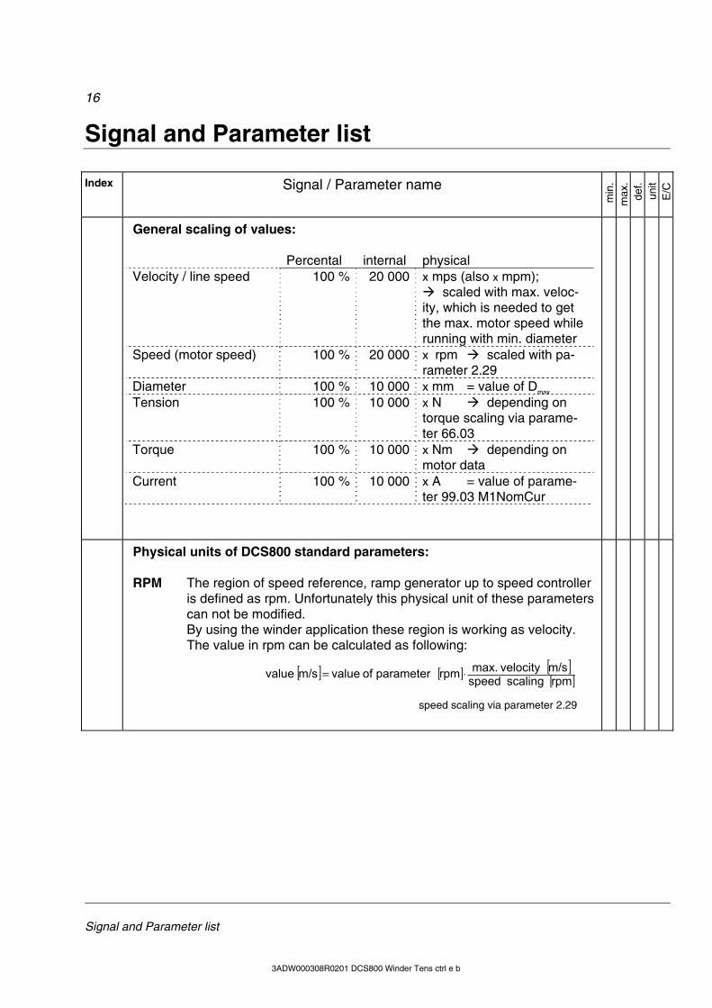
General scaling of values: Percental internal physical Velocity / line speed 100 % 20 000 x mps (also x mpm);
scaled with max. veloc-ity, which is needed to get the max. motor speed while running with min. diameter
Speed (motor speed) 100 % 20 000 x rpm scaled with pa-rameter 2.29
Diameter 100 % 10 000 x mm = value of Dmax Tension 100 % 10 000 x N depending on
torque scaling via parame-ter 66.03
Torque 100 % 10 000 x Nm depending on motor data
Current 100 % 10 000 x A = value of parame-ter 99.03 M1NomCur
Physical units of DCS800 standard parameters: RPM The region of speed reference, ramp generator up to speed controller
is defined as rpm. Unfortunately this physical unit of these parameters can not be modified. By using the winder application these region is working as velocity. The value in rpm can be calculated as following:
[ ] [ ] [ ][ ]rpm scaling speedm/svelocity max.rpm parameter of valuem/s value ⋅=
speed scaling via parameter 2.29
17
Signal and Parameter list
3ADW000308R0201 DCS800 Winder Tens ctrl e b
Index Signal / Parameter name
min
. m
ax.
def.
unit
E/C
Gro
up
7 Control Words
additional to standard firmware
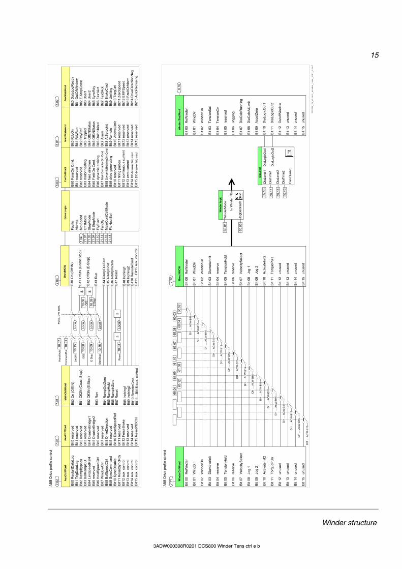
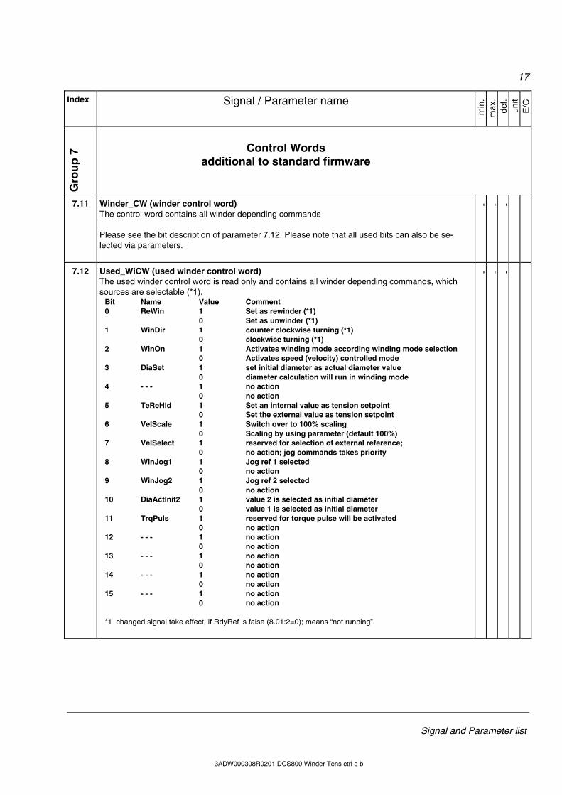
7.11 Winder_CW (winder control word) The control word contains all winder depending commands Please see the bit description of parameter 7.12. Please note that all used bits can also be se-lected via parameters.
- - -
7.12 Used_WiCW (used winder control word) The used winder control word is read only and contains all winder depending commands, which sources are selectable (*1).
Bit Name Value Comment 0 ReWin 1 Set as rewinder (*1) 0 Set as unwinder (*1) 1 WinDir 1 counter clockwise turning (*1) 0 clockwise turning (*1) 2 WinOn 1 Activates winding mode according winding mode selection 0 Activates speed (velocity) controlled mode 3 DiaSet 1 set initial diameter as actual diameter value 0 diameter calculation will run in winding mode 4 - - - 1 no action 0 no action 5 TeReHld 1 Set an internal value as tension setpoint 0 Set the external value as tension setpoint 6 VelScale 1 Switch over to 100% scaling 0 Scaling by using parameter (default 100%) 7 VelSelect 1 reserved for selection of external reference; 0 no action; jog commands takes priority 8 WinJog1 1 Jog ref 1 selected 0 no action 9 WinJog2 1 Jog ref 2 selected 0 no action 10 DiaActInit2 1 value 2 is selected as initial diameter 0 value 1 is selected as initial diameter 11 TrqPuls 1 reserved for torque pulse will be activated 0 no action 12 - - - 1 no action 0 no action 13 - - - 1 no action 0 no action 14 - - - 1 no action 0 no action 15 - - - 1 no action 0 no action *1 changed signal take effect, if RdyRef is false (8.01:2=0); means “not running”.
- - -
18
Signal and Parameter list
3ADW000308R0101 DCS800 Winder Tens ctrl e a 3ADW000308R0201 DCS800 Winder Tens ctrl e b
Index Signal / Parameter name
min
. m
ax.
def.
unit
E/C
Gro
up
8 Status Words
additional to standard firmware
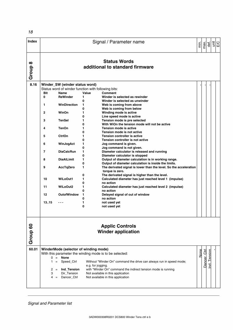
8.16 Winder_SW (winder status word) Status word of winder function with following bits:
Bit Name Value Comment 0 ReWinder 1 Winder is selected as rewinder 0 Winder is selected as unwinder 1 WinDirection 1 Web is coming from above 0 Web is coming from below 2 WinOn 1 Winding mode is active 0 Line speed mode is active 3 TenSel 1 Tension mode is pre selected 0 With WiOn the tension mode will not be active 4 TenOn 1 Tension mode is active 0 Tension mode is not active 5 CtrlOn 1 Tension controller is active 0 Tension controller is not active 6 WinJogAct 1 Jog command is given. 0 Jog command is not given. 7 DiaCalcRun 1 Diameter calculator is released and running 0 Diameter calculator is stopped 8 DiaAtLimit 1 Output of diameter calculation is in working range. 0 Output of diameter calculation is inside the limits. 9 AccTqZero 1 The derivated signal is lower than the level. So the acceleration
torque is zero. 0 The derivated signal is higher than the level. 10 WiLoOut1 1 Calculated diameter has just reached level 1 (impulse) 0 no action 11 WiLoOut2 1 Calculated diameter has just reached level 2 (impulse) 0 no action 12 OutofWindow 1 Delayed signal of out of window 0 no action 13..15 - - - 1 not used yet 0 not used yet
- - -
Gro
up
60 Applic Controls
Winder application
60.01 WinderMode (selector of winding mode) With this parameter the winding mode is to be selected:
0 = None 1 = Speed_Ctrl Without “Winder On” command the drive can always run in speed mode;
e.g. for jogging. 2 = Ind_Tension with “Winder On” command the indirect tension mode is running 3 Dir_Tension Not available in this application 4 = Dancer_Ctrl Not available in this application
Non
eD
ance
rC
trl
Ind
Ten
sion
-
19
Signal and Parameter list
3ADW000308R0201 DCS800 Winder Tens ctrl e b
Index Signal / Parameter name
min
. m
ax.
def.
unit
E/C
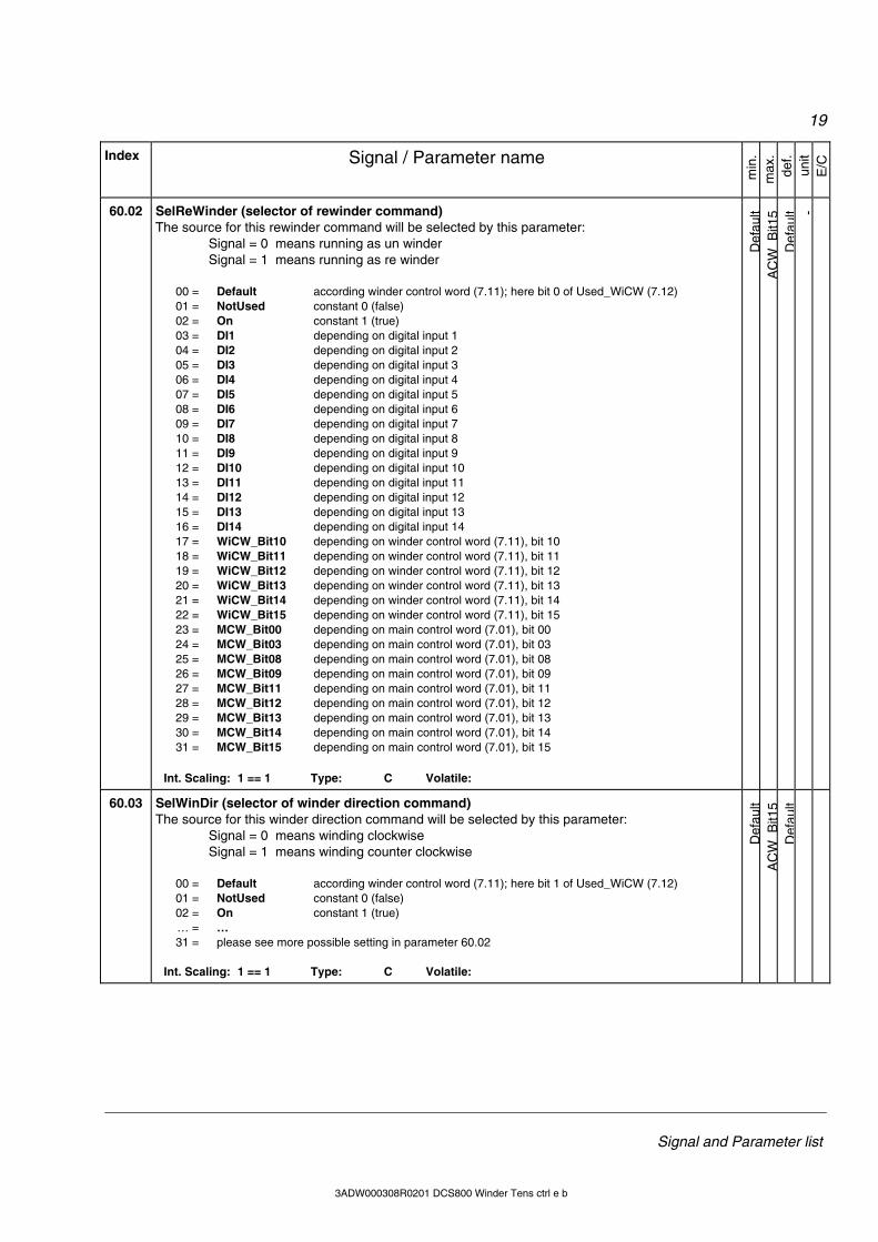
60.02 SelReWinder (selector of rewinder command) The source for this rewinder command will be selected by this parameter: Signal = 0 means running as un winder Signal = 1 means running as re winder 00 = Default according winder control word (7.11); here bit 0 of Used_WiCW (7.12) 01 = NotUsed constant 0 (false) 02 = On constant 1 (true) 03 = DI1 depending on digital input 1 04 = DI2 depending on digital input 2 05 = DI3 depending on digital input 3 06 = DI4 depending on digital input 4 07 = DI5 depending on digital input 5 08 = DI6 depending on digital input 6 09 = DI7 depending on digital input 7 10 = DI8 depending on digital input 8 11 = DI9 depending on digital input 9 12 = DI10 depending on digital input 10 13 = DI11 depending on digital input 11 14 = DI12 depending on digital input 12 15 = DI13 depending on digital input 13 16 = DI14 depending on digital input 14 17 = WiCW_Bit10 depending on winder control word (7.11), bit 10 18 = WiCW_Bit11 depending on winder control word (7.11), bit 11 19 = WiCW_Bit12 depending on winder control word (7.11), bit 12 20 = WiCW_Bit13 depending on winder control word (7.11), bit 13 21 = WiCW_Bit14 depending on winder control word (7.11), bit 14 22 = WiCW_Bit15 depending on winder control word (7.11), bit 15 23 = MCW_Bit00 depending on main control word (7.01), bit 00 24 = MCW_Bit03 depending on main control word (7.01), bit 03 25 = MCW_Bit08 depending on main control word (7.01), bit 08 26 = MCW_Bit09 depending on main control word (7.01), bit 09 27 = MCW_Bit11 depending on main control word (7.01), bit 11 28 = MCW_Bit12 depending on main control word (7.01), bit 12 29 = MCW_Bit13 depending on main control word (7.01), bit 13 30 = MCW_Bit14 depending on main control word (7.01), bit 14 31 = MCW_Bit15 depending on main control word (7.01), bit 15
Int. Scaling: 1 == 1 Type: C Volatile:
Def
ault
AC
WB
it15
Def
ault -
60.03 SelWinDir (selector of winder direction command) The source for this winder direction command will be selected by this parameter: Signal = 0 means winding clockwise Signal = 1 means winding counter clockwise 00 = Default according winder control word (7.11); here bit 1 of Used_WiCW (7.12) 01 = NotUsed constant 0 (false) 02 = On constant 1 (true) … = … 31 = please see more possible setting in parameter 60.02
Int. Scaling: 1 == 1 Type: C Volatile:
Def
ault
AC
WB
it15
Def
ault
20
Signal and Parameter list
3ADW000308R0101 DCS800 Winder Tens ctrl e a 3ADW000308R0201 DCS800 Winder Tens ctrl e b
Index Signal / Parameter name
min
. m
ax.
def.
unit
E/C
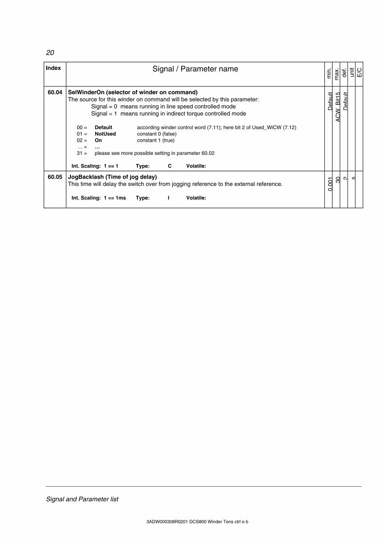
60.04 SelWinderOn (selector of winder on command) The source for this winder on command will be selected by this parameter: Signal = 0 means running in line speed controlled mode Signal = 1 means running in indirect torque controlled mode 00 = Default according winder control word (7.11); here bit 2 of Used_WiCW (7.12) 01 = NotUsed constant 0 (false) 02 = On constant 1 (true) … = … 31 = please see more possible setting in parameter 60.02
Int. Scaling: 1 == 1 Type: C Volatile:
Def
ault
AC
WB
it15
Def
ault
60.05 JogBacklash (Time of jog delay) This time will delay the switch over from jogging reference to the external reference.
Int. Scaling: 1 == 1ms Type: I Volatile:
0,00
1 30 2 s
21
Signal and Parameter list
3ADW000308R0201 DCS800 Winder Tens ctrl e b
Index Signal / Parameter name
min
. m
ax.
def.
unit
E/C
Gro
up
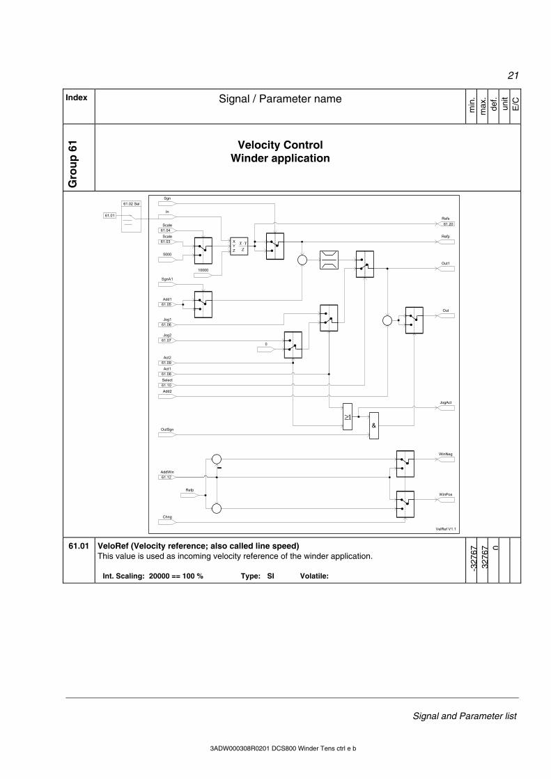
61 Velocity Control
Winder application
In
Scale
Scale
5000
SgnA1
Add1
ZYX ⋅X
YZ
10000
Sgn
Refs
Refp
Out
0
Jog1
Jog2
Act2
Act1
1≥&
OutSgn
JogAct
Select
Add2
Out1
Chng
AddWin
WinNeg
WinPosRefp
VelRef V1.1
61.04
61.02 Sel
61.01
61.03
61.05
61.06
61.07
61.09
61.08
61.10
61.12
61.20
61.01 VeloRef (Velocity reference; also called line speed) This value is used as incoming velocity reference of the winder application.
Int. Scaling: 20000 == 100 % Type: SI Volatile:
-327
6732
767 0
22
Signal and Parameter list
3ADW000308R0101 DCS800 Winder Tens ctrl e a 3ADW000308R0201 DCS800 Winder Tens ctrl e b
Index Signal / Parameter name
min
. m
ax.
def.
unit
E/C
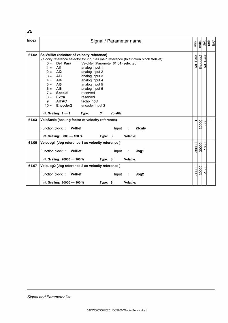
61.02 SelVelRef (selector of velocity reference) Velocity reference selector for input as main reference (to function block VelRef): 0 = Def_Para VeloRef (Parameter 61.01) selected 1 = AI1 analog input 1 2 = AI2 analog input 2 3 = AI3 analog input 3 4 = AI4 analog input 4 5 = AI5 analog input 5 6 = AI6 analog input 6 7 = Special reserved 8 = Extra reserved 9 = AITAC tacho input 10 = Encoder2 encoder input 2
Int. Scaling: 1 == 1 Type: C Volatile:
Def
Par
aE
ncod
er2
Def
Par
a -
61.03 VeloScale (scaling factor of velocity reference) Function block : VelRef Input : iScale
Int. Scaling: 5000 == 100 % Type: SI Volatile:
130
000
5000
-
61.06 VeloJog1 (Jog reference 1 as velocity reference ) Function block : VelRef Input : Jog1
Int. Scaling: 20000 == 100 % Type: SI Volatile:
-300
0030
000
1000
61.07 VeloJog2 (Jog reference 2 as velocity reference ) Function block : VelRef Input : Jog2
Int. Scaling: 20000 == 100 % Type: SI Volatile:
-300
0030
000
-100
0
23
Signal and Parameter list
3ADW000308R0201 DCS800 Winder Tens ctrl e b
Index Signal / Parameter name
min
. m
ax.
def.
unit
E/C
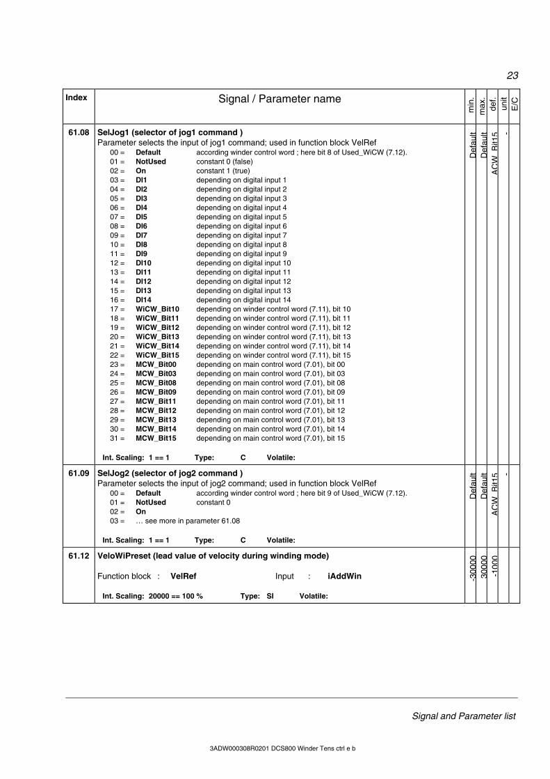
61.08 SelJog1 (selector of jog1 command ) Parameter selects the input of jog1 command; used in function block VelRef 00 = Default according winder control word ; here bit 8 of Used_WiCW (7.12). 01 = NotUsed constant 0 (false) 02 = On constant 1 (true) 03 = DI1 depending on digital input 1 04 = DI2 depending on digital input 2 05 = DI3 depending on digital input 3 06 = DI4 depending on digital input 4 07 = DI5 depending on digital input 5 08 = DI6 depending on digital input 6 09 = DI7 depending on digital input 7 10 = DI8 depending on digital input 8 11 = DI9 depending on digital input 9 12 = DI10 depending on digital input 10 13 = DI11 depending on digital input 11 14 = DI12 depending on digital input 12 15 = DI13 depending on digital input 13 16 = DI14 depending on digital input 14 17 = WiCW_Bit10 depending on winder control word (7.11), bit 10 18 = WiCW_Bit11 depending on winder control word (7.11), bit 11 19 = WiCW_Bit12 depending on winder control word (7.11), bit 12 20 = WiCW_Bit13 depending on winder control word (7.11), bit 13 21 = WiCW_Bit14 depending on winder control word (7.11), bit 14 22 = WiCW_Bit15 depending on winder control word (7.11), bit 15 23 = MCW_Bit00 depending on main control word (7.01), bit 00 24 = MCW_Bit03 depending on main control word (7.01), bit 03 25 = MCW_Bit08 depending on main control word (7.01), bit 08 26 = MCW_Bit09 depending on main control word (7.01), bit 09 27 = MCW_Bit11 depending on main control word (7.01), bit 11 28 = MCW_Bit12 depending on main control word (7.01), bit 12 29 = MCW_Bit13 depending on main control word (7.01), bit 13 30 = MCW_Bit14 depending on main control word (7.01), bit 14 31 = MCW_Bit15 depending on main control word (7.01), bit 15
Int. Scaling: 1 == 1 Type: C Volatile:
Def
ault
Def
ault
AC
WB
it15 -
61.09 SelJog2 (selector of jog2 command ) Parameter selects the input of jog2 command; used in function block VelRef 00 = Default according winder control word ; here bit 9 of Used_WiCW (7.12). 01 = NotUsed constant 0 02 = On 03 = … see more in parameter 61.08
Int. Scaling: 1 == 1 Type: C Volatile:
Def
ault
Def
ault
AC
WB
it15 -
61.12 VeloWiPreset (lead value of velocity during winding mode) Function block : VelRef Input : iAddWin
Int. Scaling: 20000 == 100 % Type: SI Volatile:
-300
0030
000
-100
0
24
Signal and Parameter list
3ADW000308R0101 DCS800 Winder Tens ctrl e a 3ADW000308R0201 DCS800 Winder Tens ctrl e b
Index Signal / Parameter name
min
. m
ax.
def.
unit
E/C
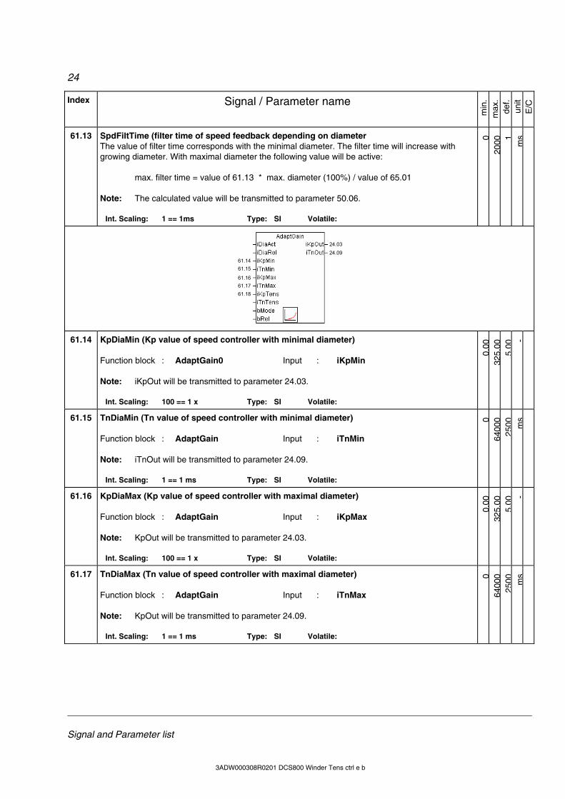
61.13 SpdFiltTime (filter time of speed feedback depending on diameter The value of filter time corresponds with the minimal diameter. The filter time will increase with growing diameter. With maximal diameter the following value will be active: max. filter time = value of 61.13 * max. diameter (100%) / value of 65.01 Note: The calculated value will be transmitted to parameter 50.06.
Int. Scaling: 1 == 1ms Type: SI Volatile:
020
00 1m
s
61.1461.15
61.1661.1761.18
24.0324.09
61.14 KpDiaMin (Kp value of speed controller with minimal diameter) Function block : AdaptGain0 Input : iKpMin Note: iKpOut will be transmitted to parameter 24.03.
Int. Scaling: 100 == 1 x Type: SI Volatile:
0.00
325.
005.
00-
61.15 TnDiaMin (Tn value of speed controller with minimal diameter) Function block : AdaptGain Input : iTnMin Note: iTnOut will be transmitted to parameter 24.09.
Int. Scaling: 1 == 1 ms Type: SI Volatile: 0
6400
025
00 ms
61.16 KpDiaMax (Kp value of speed controller with maximal diameter) Function block : AdaptGain Input : iKpMax Note: KpOut will be transmitted to parameter 24.03.
Int. Scaling: 100 == 1 x Type: SI Volatile:
0.00
325.
005.
00-
61.17 TnDiaMax (Tn value of speed controller with maximal diameter) Function block : AdaptGain Input : iTnMax Note: KpOut will be transmitted to parameter 24.09.
Int. Scaling: 1 == 1 ms Type: SI Volatile:
064
000
2500 m
s
25
Signal and Parameter list
3ADW000308R0201 DCS800 Winder Tens ctrl e b
Index Signal / Parameter name
min
. m
ax.
def.
unit
E/C
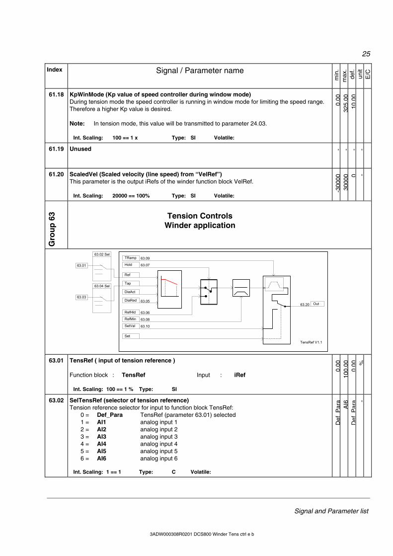
61.18 KpWinMode (Kp value of speed controller during window mode) During tension mode the speed controller is running in window mode for limiting the speed range. Therefore a higher Kp value is desired. Note: In tension mode, this value will be transmitted to parameter 24.03.
Int. Scaling: 100 == 1 x Type: SI Volatile:
0.00
325.
0010
.00
61.19 Unused
- - - -
61.20 ScaledVel (Scaled velocity (line speed) from “VelRef”) This parameter is the output iRefs of the winder function block VelRef.
Int. Scaling: 20000 == 100% Type: SI Volatile:
-300
0030
000 0 -
Gro
up
63 Tension Controls
Winder application
63.09
63.02 Sel
63.01
RefHld
Ref
Tap
DiaAct
DiaRed
Hold
RefMin
TRamp
Out
SetVal
Set
TensRef V1.1
63.04 Sel
63.03
63.07
63.05
63.06
63.08
63.10
63.20
63.01 TensRef ( input of tension reference )
Function block : TensRef Input : iRef
Int. Scaling: 100 == 1 % Type: SI
0.00
100.
000.
00 %
63.02 SelTensRef (selector of tension reference) Tension reference selector for input to function block TensRef: 0 = Def_Para TensRef (parameter 63.01) selected 1 = AI1 analog input 1 2 = AI2 analog input 2 3 = AI3 analog input 3 4 = AI4 analog input 4 5 = AI5 analog input 5 6 = AI6 analog input 6
Int. Scaling: 1 == 1 Type: C Volatile:
Def
Par
aA
I6D
efP
ara -
26
Signal and Parameter list
3ADW000308R0101 DCS800 Winder Tens ctrl e a 3ADW000308R0201 DCS800 Winder Tens ctrl e b
Index Signal / Parameter name
min
. m
ax.
def.
unit
E/C
63.03 TapTens ( reduction of tension dependend on diameter ) Function block : TensRef Input : iTap
Int. Scaling: 100 == 1 % Type: SI
0.00
100.
000.
00 %
63.05 TapDia ( value as from the tension reduction begins ) Function block : TensRef Input : iDiaRed
Int. Scaling: 100 == 1 % Type: SI
1.00
100.
001.
00 %
63.06 TeRefHold ( tension reference if hold command is active ) This tension reference will be active instead of external tension reference, if the incoming com-mand, selected in 63.07, is active.
Int. Scaling: 100 == 1 % Type: SI
0.00
100.
0015
.00 %
63.07 SelTeRefHld (selector of hold tension command ) Parameter selects the input of tension hold reference command; used in function block TensRef 00 = Default according winder control word ; here bit 5 of Used_WiCW (7.12). 01 = NotUsed constant 0 (false) 02 = On constant 1 (true) 03 = … see more in parameter 61.08
Int. Scaling: 1 == 1 Type: C Volatile:
Def
ault
Def
ault
AC
WB
it15 -
63.08 TeRefMin (minimal tension reference) Function block : TensRef Input : iRefMinw
Int. Scaling: 100 == 1 % Type: SI
0.00
100.
001.
00 %
63.20 TeRefOut (Tension reference output of TensRef) Function block : TensRef Input : iOut
Int. Scaling: 100 == 1 % Type: SI -3
20.0
032
0.00
0.00 %
27
Signal and Parameter list
3ADW000308R0201 DCS800 Winder Tens ctrl e b
Index Signal / Parameter name
min
. m
ax.
def.
unit
E/C
Gro
up
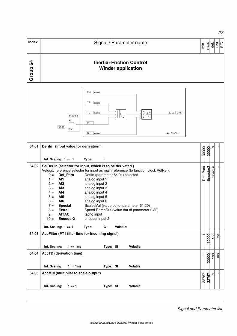
64 Inertia+Friction Control
Winder application
AccFilt V1.1
ZYX ⋅X
YZ
Dout
Mul
TF
TD
In
Div 64.06
64.04
64.03
64.05
64.4064.02 Sel
AI
64.01Enc
64.01 DeriIn (input value for derivation )
Int. Scaling: 1 == 1 Type: I
-300
0030
000 0 -
64.02 SelDeriIn (selector for input, which is to be derivated ) Velocity reference selector for input as main reference (to function block VelRef): 0 = Def_Para DeriIn (parameter 64.01) selected 1 = AI1 analog input 1 2 = AI2 analog input 2 3 = AI3 analog input 3 4 = AI4 analog input 4 5 = AI5 analog input 5 6 = AI6 analog input 6 7 = Special ScaledVal (value out of parameter 61.20) 8 = Extra Speed RampOut (value out of parameter 2.32) 9 = AITAC tacho input 10 = Encoder2 encoder input 2
Int. Scaling: 1 == 1 Type: C Volatile:
Def
Par
aE
ncod
er2
Spe
cial -
64.03 AccFilter (PT1 filter time for incoming signal)
Int. Scaling: 1 == 1ms Type: SI Volatile:
130
000
100
ms
64.04 AccTD (derivation time)
Int. Scaling: 1 == 1ms Type: SI Volatile:
130
000
100
ms
64.05 AccMul (multiplier to scale output)
Int. Scaling: 1 == 1 Type: SI Volatile:
-327
6732
767 1 -
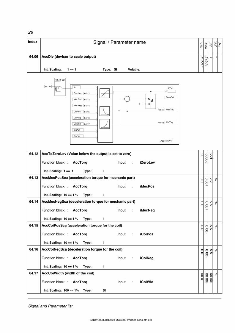
28
Signal and Parameter list
3ADW000308R0101 DCS800 Winder Tens ctrl e a 3ADW000308R0201 DCS800 Winder Tens ctrl e b
Index Signal / Parameter name
min
. m
ax.
def.
unit
E/C
64.06 AccDiv (devisor to scale output)
Int. Scaling: 1 == 1 Type: SI Volatile:
-327
6732
767 1 -
64.15
64.14
64.13
64.12
64.42
ZOut
AccTorq V1.1
In
ZeroLev
MecPos
MecNeg
CoiPos
CoiNeg
CoiWid
DiaAct
DiaRel
0
SumOut
MecTrq
CoiTrq
64.11 Sel
AI
64.10 Enc
64.17
64.16
64.41
64.12 AccTqZeroLev (Value below the output is set to zero) Function block : AccTorq Input : iZeroLev
Int. Scaling: 1 == 1 Type: I
020
000
100
64.13 AccMecPosSca (acceleration torque for mechanic part) Function block : AccTorq Input : iMecPos
Int. Scaling: 10 == 1 % Type: I
0.0
100.
00.
0 %
64.14 AccMecNegSca (deceleration torque for mechanic part) Function block : AccTorq Input : iMecNeg
Int. Scaling: 10 == 1 % Type: I
0.0
100.
00.
0 %
64.15 AccCoiPosSca (acceleration torque for the coil) Function block : AccTorq Input : iCoiPos
Int. Scaling: 10 == 1 % Type: I
0.0
100.
00.
0 %
64.16 AccCoiNegSca (deceleration torque for the coil) Function block : AccTorq Input : iCoiNeg
Int. Scaling: 10 == 1 % Type: I
0.0
100.
00.
0 %
64.17 AccCoiWidth (width of the coil) Function block : AccTorq Input : iCoiWid
Int. Scaling: 100 == 1% Type: SI
0.00
100.
0010
0.00 %
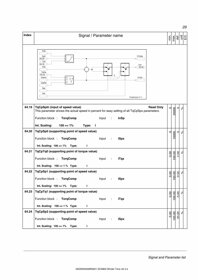
29
Signal and Parameter list
3ADW000308R0201 DCS800 Winder Tens ctrl e b
Index Signal / Parameter name
min
. m
ax.
def.
unit
E/C
ZYX ⋅X
YZ
TqDia
DiaAct
DiaRel
InSp
SpX
TqX
AddOut
OTqSp
OTqD0
Sgn
Rel
TorqComp V1.1
63.34
26.02
63.20
63.33
...
64.19 TqCpSpIn (input of speed value) Read Only This parameter shows the actual speed in percent for easy setting of all TqCpSpx parameters. Function block : TorqComp Input : inSp Int. Scaling: 100 == 1% Type: I
020
000 0 %
64.20 TqCpSp0 (supporting point of speed value) Function block : TorqComp Input : iSpx
Int. Scaling: 100 == 1% Type: I
010
000 0 %
64.21 TqCpTq0 (supporting point of torque value) Function block : TorqComp Input : iTqx
Int. Scaling: 100 == 1 % Type: I
0.00
100.
002.
00 %
64.22 TqCpSp1 (supporting point of speed value) Function block : TorqComp Input : iSpx
Int. Scaling: 100 == 1% Type: I
0.00
100.
000.
50 %
64.23 TqCpTq1 (supporting point of torque value) Function block : TorqComp Input : iTqx
Int. Scaling: 100 == 1 % Type: I
0.00
100.
000.
00 %
64.24 TqCpSp2 (supporting point of speed value) Function block : TorqComp Input : iSpx
Int. Scaling: 100 == 1% Type: I
0.00
100.
0020
.00 %
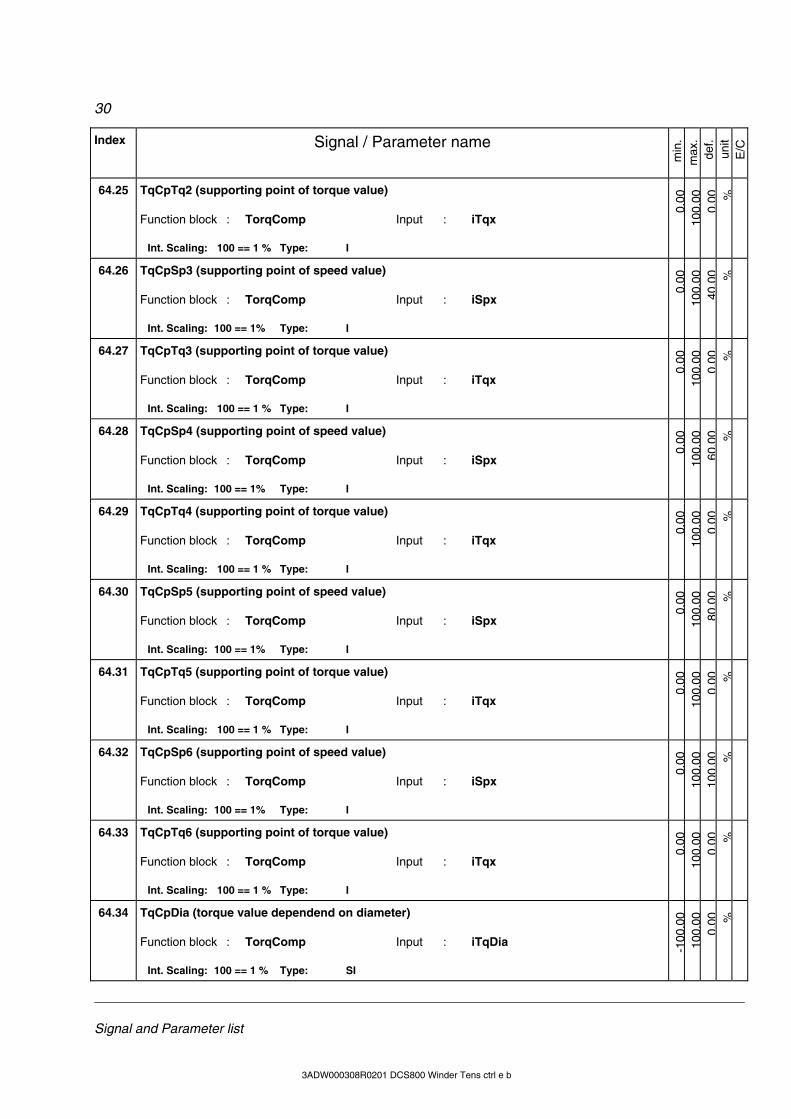
30
Signal and Parameter list
3ADW000308R0101 DCS800 Winder Tens ctrl e a 3ADW000308R0201 DCS800 Winder Tens ctrl e b
Index Signal / Parameter name
min
. m
ax.
def.
unit
E/C
64.25 TqCpTq2 (supporting point of torque value) Function block : TorqComp Input : iTqx
Int. Scaling: 100 == 1 % Type: I
0.00
100.
000.
00 %
64.26 TqCpSp3 (supporting point of speed value) Function block : TorqComp Input : iSpx
Int. Scaling: 100 == 1% Type: I
0.00
100.
0040
.00 %
64.27 TqCpTq3 (supporting point of torque value) Function block : TorqComp Input : iTqx
Int. Scaling: 100 == 1 % Type: I
0.00
100.
000.
00 %
64.28 TqCpSp4 (supporting point of speed value) Function block : TorqComp Input : iSpx
Int. Scaling: 100 == 1% Type: I
0.00
100.
0060
.00 %
64.29 TqCpTq4 (supporting point of torque value) Function block : TorqComp Input : iTqx
Int. Scaling: 100 == 1 % Type: I
0.00
100.
000.
00 %
64.30 TqCpSp5 (supporting point of speed value) Function block : TorqComp Input : iSpx
Int. Scaling: 100 == 1% Type: I
0.00
100.
0080
.00 %
64.31 TqCpTq5 (supporting point of torque value) Function block : TorqComp Input : iTqx
Int. Scaling: 100 == 1 % Type: I
0.00
100.
000.
00 %
64.32 TqCpSp6 (supporting point of speed value) Function block : TorqComp Input : iSpx
Int. Scaling: 100 == 1% Type: I
0.00
100.
0010
0.00 %
64.33 TqCpTq6 (supporting point of torque value) Function block : TorqComp Input : iTqx
Int. Scaling: 100 == 1 % Type: I
0.00
100.
000.
00 %
64.34 TqCpDia (torque value dependend on diameter) Function block : TorqComp Input : iTqDia
Int. Scaling: 100 == 1 % Type: SI
-100
.00
100.
000.
00 %
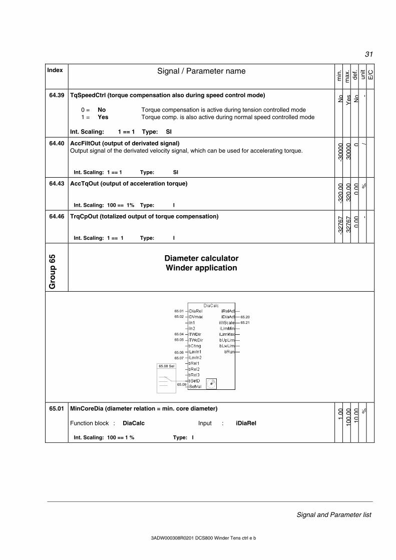
31
Signal and Parameter list
3ADW000308R0201 DCS800 Winder Tens ctrl e b
Index Signal / Parameter name
min
. m
ax.
def.
unit
E/C
64.39 TqSpeedCtrl (torque compensation also during speed control mode) 0 = No Torque compensation is active during tension controlled mode 1 = Yes Torque comp. is also active during normal speed controlled mode Int. Scaling: 1 == 1 Type: SI
No
Yes No -
64.40 AccFiltOut (output of derivated signal) Output signal of the derivated velocity signal, which can be used for accelerating torque.
Int. Scaling: 1 == 1 Type: SI
-300
0030
000 0 /
64.43 AccTqOut (output of acceleration torque)
Int. Scaling: 100 == 1% Type: I
-320
.00
320.
000.
00 %
64.46 TrqCpOut (totalized output of torque compensation)
Int. Scaling: 1 == 1 Type: I
-327
6732
767
0.00
-
Gro
up
65 Diameter calculator
Winder application
65.08 Sel
65.09
65.0165.02
65.0465.05
65.0665.07
65.2065.21
65.01 MinCoreDia (diameter relation = min. core diameter) Function block : DiaCalc Input : iDiaRel
Int. Scaling: 100 == 1 % Type: I
1.00
100.
0010
.00 %
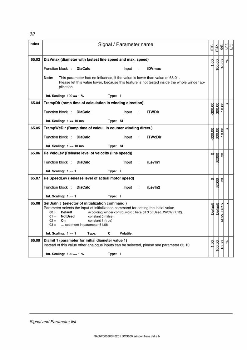
32
Signal and Parameter list
3ADW000308R0101 DCS800 Winder Tens ctrl e a 3ADW000308R0201 DCS800 Winder Tens ctrl e b
Index Signal / Parameter name
min
. m
ax.
def.
unit
E/C
65.02 DiaVmax (diameter with fastest line speed and max. speed) Function block : DiaCalc Input : iDVmax Note: This parameter has no influence, if the value is lower than value of 65.01.
Please let this value lower, because this feature is not tested inside the whole winder ap-plication.
Int. Scaling: 100 == 1 % Type: I
1.00
100.
0010
.00 %
65.04 TrampDir (ramp time of calculation in winding direction) Function block : DiaCalc Input : iTWDir
Int. Scaling: 1 == 10 ms Type: SI
-300
.00
300.
0010
.00 s
65.05 TrampWcDir (Ramp time of calcul. in counter winding direct.) Function block : DiaCalc Input : iTWcDir
Int. Scaling: 1 == 10 ms Type: SI
-300
.00
300.
0010
.00 s
65.06 RelVeloLev (Release level of velocity (line speed)) Function block : DiaCalc Input : iLevIn1
Int. Scaling: 1 == 1 Type: I
032
000 20
65.07 RelSpeedLev (Release level of actual motor speed) Function block : DiaCalc Input : iLevIn2
Int. Scaling: 1 == 1 Type: I
032
000 20
65.08 SelDiaInit (selector of initialization command ) Parameter selects the input of initialization command for setting the initial value. 00 = Default according winder control word ; here bit 3 of Used_WiCW (7.12). 01 = NotUsed constant 0 (false) 02 = On constant 1 (true) 03 = … see more in parameter 61.08
Int. Scaling: 1 == 1 Type: C Volatile:
Def
ault
Def
ault
AC
WB
it15 -
65.09 DiaInit 1 (parameter for initial diameter value 1) Instead of this value other analogue inputs can be selected, please see parameter 65.10
Int. Scaling: 100 == 1 % Type: I
1.00
100.
0010
.00 %
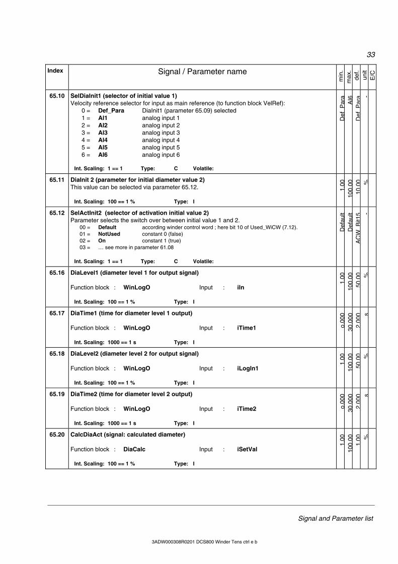
33
Signal and Parameter list
3ADW000308R0201 DCS800 Winder Tens ctrl e b
Index Signal / Parameter name
min
. m
ax.
def.
unit
E/C
65.10 SelDiaInit1 (selector of initial value 1) Velocity reference selector for input as main reference (to function block VelRef): 0 = Def_Para DiaInit1 (parameter 65.09) selected 1 = AI1 analog input 1 2 = AI2 analog input 2 3 = AI3 analog input 3 4 = AI4 analog input 4 5 = AI5 analog input 5 6 = AI6 analog input 6
Int. Scaling: 1 == 1 Type: C Volatile:
Def
Par
aA
I6D
efP
ara -
65.11 DiaInit 2 (parameter for initial diameter value 2) This value can be selected via parameter 65.12.
Int. Scaling: 100 == 1 % Type: I
1.00
100.
0010
.00 %
65.12 SelActInit2 (selector of activation initial value 2) Parameter selects the switch over between initial value 1 and 2. 00 = Default according winder control word ; here bit 10 of Used_WiCW (7.12). 01 = NotUsed constant 0 (false) 02 = On constant 1 (true) 03 = … see more in parameter 61.08
Int. Scaling: 1 == 1 Type: C Volatile:
Def
ault
Def
ault
AC
WB
it15 -
65.16 DiaLevel1 (diameter level 1 for output signal) Function block : WinLogO Input : iIn
Int. Scaling: 100 == 1 % Type: I
1.00
100.
0050
.00 %
65.17 DiaTime1 (time for diameter level 1 output) Function block : WinLogO Input : iTime1
Int. Scaling: 1000 == 1 s Type: I o.
000
30.0
002.
000 s
65.18 DiaLevel2 (diameter level 2 for output signal) Function block : WinLogO Input : iLogIn1
Int. Scaling: 100 == 1 % Type: I
1.00
100.
0050
.00 %
65.19 DiaTime2 (time for diameter level 2 output) Function block : WinLogO Input : iTime2
Int. Scaling: 1000 == 1 s Type: I
o.00
030
.000
2.00
0 s
65.20 CalcDiaAct (signal: calculated diameter) Function block : DiaCalc Input : iSetVal
Int. Scaling: 100 == 1 % Type: I
1.00
100.
001.
00 %
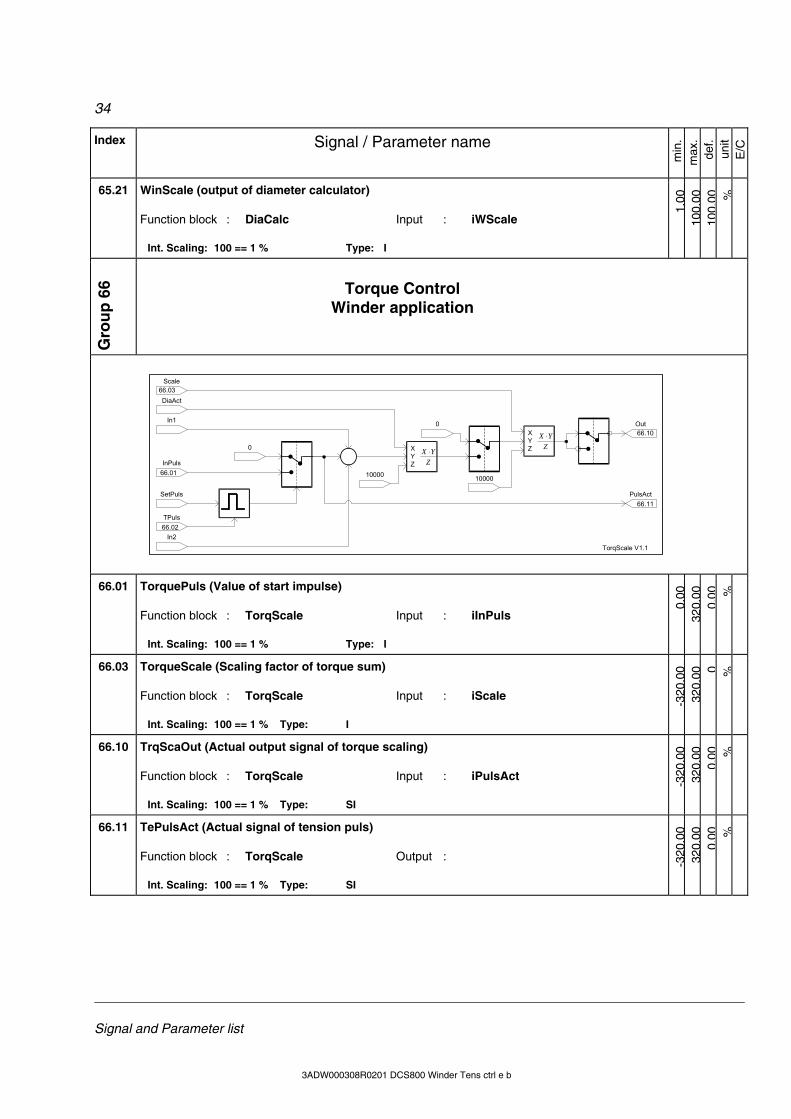
34
Signal and Parameter list
3ADW000308R0101 DCS800 Winder Tens ctrl e a 3ADW000308R0201 DCS800 Winder Tens ctrl e b
Index Signal / Parameter name
min
. m
ax.
def.
unit
E/C
65.21 WinScale (output of diameter calculator) Function block : DiaCalc Input : iWScale
Int. Scaling: 100 == 1 % Type: I
1.00
100.
0010
0.00 %
Gro
up
66 Torque Control
Winder application
ZYX ⋅X
YZ
ZYX ⋅X
YZ
SetPuls
TPuls
0
InPuls
In1
In2
10000
DiaAct
0
10000
Scale
Out
PulsAct
TorqScale V1.1
66.01
66.02
66.10
66.11
66.03
66.01 TorquePuls (Value of start impulse) Function block : TorqScale Input : iInPuls
Int. Scaling: 100 == 1 % Type: I
0.00
320.
000.
00 %
66.03 TorqueScale (Scaling factor of torque sum) Function block : TorqScale Input : iScale
Int. Scaling: 100 == 1 % Type: I
-320
.00
320.
00 0 %
66.10 TrqScaOut (Actual output signal of torque scaling) Function block : TorqScale Input : iPulsAct
Int. Scaling: 100 == 1 % Type: SI
-320
.00
320.
000.
00 %
66.11 TePulsAct (Actual signal of tension puls) Function block : TorqScale Output :
Int. Scaling: 100 == 1 % Type: SI
-320
.00
320.
000.
00 %
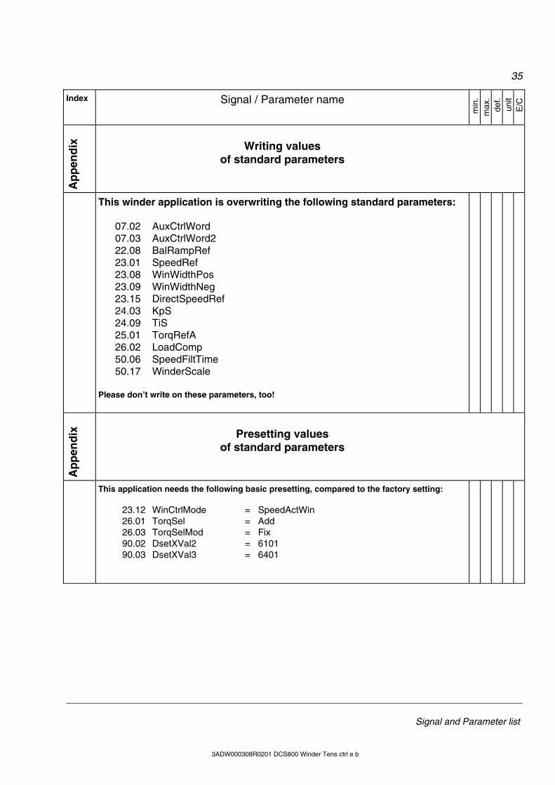
35
Signal and Parameter list
3ADW000308R0201 DCS800 Winder Tens ctrl e b
Index Signal / Parameter name
min
. m
ax.
def.
unit
E/C
Ap
pen
dix
Writing values of standard parameters
This winder application is overwriting the following standard parameters: 07.02 AuxCtrlWord 07.03 AuxCtrlWord2 22.08 BalRampRef 23.01 SpeedRef 23.08 WinWidthPos 23.09 WinWidthNeg 23.15 DirectSpeedRef 24.03 KpS 24.09 TiS 25.01 TorqRefA 26.02 LoadComp 50.06 SpeedFiltTime 50.17 WinderScale Please don’t write on these parameters, too!
Ap
pen
dix
Presetting values of standard parameters
This application needs the following basic presetting, compared to the factory setting: 23.12 WinCtrlMode = SpeedActWin 26.01 TorqSel = Add 26.03 TorqSelMod = Fix 90.02 DsetXVal2 = 6101 90.03 DsetXVal3 = 6401
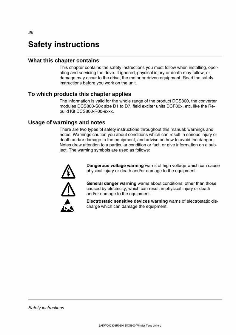
36
Safety instructions
3ADW000308R0201 DCS800 Winder Tens ctrl e b
Safety instructions
What this chapter contains This chapter contains the safety instructions you must follow when installing, oper-
ating and servicing the drive. If ignored, physical injury or death may follow, or damage may occur to the drive, the motor or driven equipment. Read the safety instructions before you work on the unit.
To which products this chapter applies The information is valid for the whole range of the product DCS800, the converter
modules DCS800-S0x size D1 to D7, field exciter units DCF80x, etc. like the Re-build Kit DCS800-R00-9xxx.
Usage of warnings and notes There are two types of safety instructions throughout this manual: warnings and
notes. Warnings caution you about conditions which can result in serious injury or death and/or damage to the equipment, and advise on how to avoid the danger. Notes draw attention to a particular condition or fact, or give information on a sub-ject. The warning symbols are used as follows:
Dangerous voltage warning warns of high voltage which can cause physical injury or death and/or damage to the equipment.
General danger warning warns about conditions, other than those caused by electricity, which can result in physical injury or death and/or damage to the equipment.
Electrostatic sensitive devices warning warns of electrostatic dis-charge which can damage the equipment.
37
Safety instructions
3ADW000308R0201 DCS800 Winder Tens ctrl e b
Installation and maintenance work These warnings are intended for all who work on the drive, motor cable
or motor. Ignoring the instructions can cause physical injury or death and/or damage to the equipment. WARNING!
• Only qualified electricians are allowed to install and maintain
the drive! • Never work on the drive, motor cable or motor when main power is
applied. Always ensure by measuring with a multimeter (impedance at least 1 Mohm) that:
1. Voltage between drive input phases U1, V1 and W1 and the frame is close to 0 V.
2. Voltage between terminals C+ and D- and the frame is close to 0 V.
• Do not work on the control cables when power is applied to the drive or to the external control circuits. Externally supplied control circuits may cause dangerous voltages inside the drive even when the main power on the drive is switched off.
• Do not make any insulation resistance or voltage withstand tests on the drive or drive modules.
• Isolate the motor cables from the drive when testing the insulation resistance or voltage withstand of the cables or the motor.
• When reconnecting the motor cable, always check that the C+ and D- cables are connected with the proper terminal.
Note:
• The motor cable terminals on the drive are at a dangerously high voltage when the main power is on, regardless of whether the mo-tor is running or not.
• Depending on the external wiring, dangerous voltages (115 V, 220 V or 230 V) may be present on the relay outputs of the drive system (e.g. SDCS-IOB-2 and RDIO).
• DCS800 with enclosure extension: Before working on the drive, isolate the whole drive system from the supply.
38
Safety instructions
3ADW000308R0201 DCS800 Winder Tens ctrl e b
Grounding
These instructions are intended for all who are responsible for the
grounding of the drive. Incorrect grounding can cause physical injury, death and/or equipment malfunction and increase electromagnetic in-terference. WARNING!
• Ground the drive, motor and adjoining equipment to ensure per-
sonnel safety in all circumstances, and to reduce electromagnetic emission and pick-up.
• Make sure that grounding conductors are adequately sized and marked as required by safety regulations.
• In a multiple-drive installation, connect each drive separately to protective earth (PE ).
• Minimize EMC emission and make a 360° high frequency ground-ing (e.g. conductive sleeves) of screened cable entries at the cabi-net lead-through plate.
• Do not install a drive equipped with an EMC filter to an un-grounded power system or a high resistance-grounded (over 30 ohms) power system.
Note:
• Power cable shields are suitable as equipment grounding conduc-tors only when adequately sized to meet safety regulations.
• As the normal leakage current of the drive is higher than 3.5 mA AC or 10 mA DC (stated by EN 50178, 5.2.11.1), a fixed protective earth connection is required.
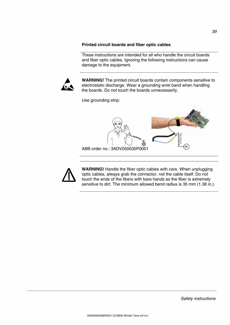
39
Safety instructions
3ADW000308R0201 DCS800 Winder Tens ctrl e b
Printed circuit boards and fiber optic cables
These instructions are intended for all who handle the circuit boards
and fiber optic cables. Ignoring the following instructions can cause damage to the equipment.
WARNING! The printed circuit boards contain components sensitive to electrostatic discharge. Wear a grounding wrist band when handling the boards. Do not touch the boards unnecessarily.
Use grounding strip:
ABB order no.: 3ADV050035P0001
WARNING! Handle the fiber optic cables with care. When unplugging optic cables, always grab the connector, not the cable itself. Do not touch the ends of the fibers with bare hands as the fiber is extremely sensitive to dirt. The minimum allowed bend radius is 35 mm (1.38 in.).
40
Safety instructions
3ADW000308R0201 DCS800 Winder Tens ctrl e b
Mechanical installation These notes are intended for all who install the drive. Handle the unit
carefully to avoid damage and injury. WARNING!
• DCS800 sizes D4 ... D7: The drive is heavy. Do not lift it alone. Do
not lift the unit by the front cover. Place units D4 and D5 only on its back. DCS800 sizes D5 ... D7: The drive is heavy. Lift the drive by the lifting lugs only. Do not tilt the unit. The unit will overturn from a tilt of about 6 degrees.
• Make sure that dust from drilling does not enter the drive when in-stalling. Electrically conductive dust inside the unit may cause damage or lead to malfunction.
• Ensure sufficient cooling. • Do not fasten the drive by riveting or welding.
41
Safety instructions
3ADW000308R0201 DCS800 Winder Tens ctrl e b
Operation These warnings are intended for all who plan the operation of the drive
or operate the drive. Ignoring the instructions can cause physical injury or death and/or damage to the equipment. WARNING!
• Before adjusting the drive and putting it into service, make sure
that the motor and all driven equipment are suitable for operation throughout the speed range provided by the drive. The drive can be adjusted to operate the motor at speeds above and below the base speed.
• Do not control the motor with the disconnecting device (discon-
necting mains); instead, use the control panel keys and , or commands via the I/O board of the drive.
• Mains connection You can use a disconnect switch (with fuses) to disconnect the electrical components of the drive from the mains for installation and maintenance work. The type of disconnect switch used must be as per EN 60947-3, Class B, so as to comply with EU regula-tions, or a circuit-breaker type which switches off the load circuit by means of an auxiliary contact causing the breaker's main contacts to open. The mains disconnect must be locked in its "OPEN" posi-tion during any installation and maintenance work.
• EMERGENCY STOP buttons must be installed at each control desk and at all other control panels requiring an emergency stop function. Pressing the STOP button on the control panel of the drive will neither cause an emergency stop of the motor, nor will the drive be disconnected from any dangerous potential. To avoid unintentional operating states, or to shut the unit down in case of any imminent danger according to the standards in the safety instructions it is not sufficient to merely shut down the drive via signals "RUN", "drive OFF" or "Emergency Stop" respectively "control panel" or "PC tool".
• Intended use The operating instructions cannot take into consideration every possible case of configuration, operation or maintenance. Thus, they mainly give such advice only, which is required by qualified personnel for normal operation of the machines and devices in in-dustrial installations. If in special cases the electrical machines and devices are in-tended for use in non-industrial installations - which may require stricter safety regulations (e.g. protection against contact by chil-dren or similar) - these additional safety measures for the installa-tion must be provided by the customer during assembly.
42
Safety instructions
3ADW000308R0201 DCS800 Winder Tens ctrl e b
Note:
• When the control location is not set to Local (L not shown in the status row of the display), the stop key on the control panel will not stop the drive. To stop the drive using the control panel, press the
LOC/REM key and then the stop key .
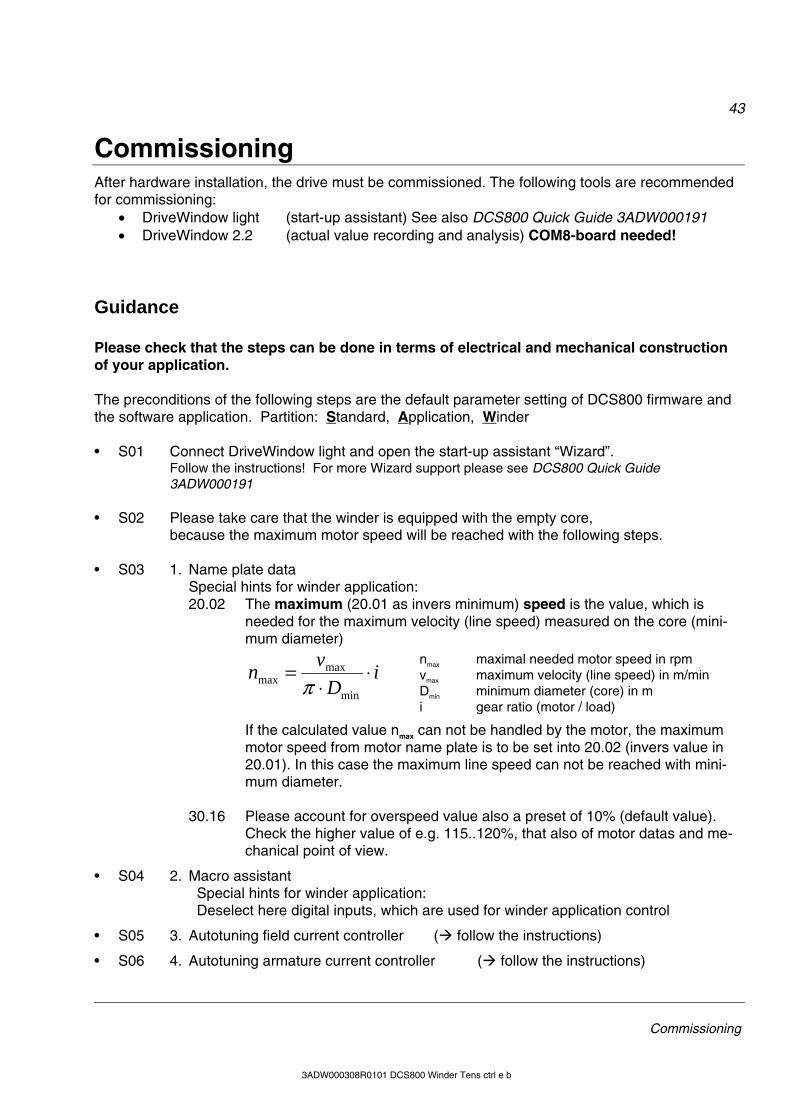
43
Commissioning
3ADW000308R0101 DCS800 Winder Tens ctrl e b
Commissioning After hardware installation, the drive must be commissioned. The following tools are recommended for commissioning:
• DriveWindow light (start-up assistant) See also DCS800 Quick Guide 3ADW000191 • DriveWindow 2.2 (actual value recording and analysis) COM8-board needed!
Guidance Please check that the steps can be done in terms of electrical and mechanical construction of your application. The preconditions of the following steps are the default parameter setting of DCS800 firmware and the software application. Partition: Standard, Application, Winder • S01 Connect DriveWindow light and open the start-up assistant “Wizard”.
Follow the instructions! For more Wizard support please see DCS800 Quick Guide 3ADW000191
• S02 Please take care that the winder is equipped with the empty core, because the maximum motor speed will be reached with the following steps.
• S03 1. Name plate data
Special hints for winder application: 20.02 The maximum (20.01 as invers minimum) speed is the value, which is
needed for the maximum velocity (line speed) measured on the core (mini-mum diameter)
iD
vn ⋅⋅
=min
maxmax π
If the calculated value nmax can not be handled by the motor, the maximum motor speed from motor name plate is to be set into 20.02 (invers value in 20.01). In this case the maximum line speed can not be reached with mini-mum diameter.
30.16 Please account for overspeed value also a preset of 10% (default value).
Check the higher value of e.g. 115..120%, that also of motor datas and me-chanical point of view.
• S04 2. Macro assistant Special hints for winder application: Deselect here digital inputs, which are used for winder application control
• S05 3. Autotuning field current controller ( follow the instructions)
• S06 4. Autotuning armature current controller ( follow the instructions)
nmax maximal needed motor speed in rpm vmax maximum velocity (line speed) in m/min Dmin minimum diameter (core) in m i gear ratio (motor / load)
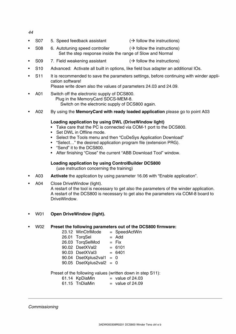
44
Commissioning
3ADW000308R0201 DCS800 Winder Tens ctrl e b
• S07 5. Speed feedback assistant ( follow the instructions)
• S08 6. Autotuning speed controller ( follow the instructions) Set the step response inside the range of Slow and Normal
• S09 7. Field weakening assistant ( follow the instructions)
• S10 Advanced: Activate all built in options, like field bus adapter an additional IOs.
• S11 It is recommended to save the parameters settings, before continuing with winder appli-cation software! Please write down also the values of parameters 24.03 and 24.09.
• A01 Switch off the electronic supply of DCS800. Plug in the MemoryCard SDCS-MEM-8. Switch on the electronic supply of DCS800 again.
• A02 By using the MemoryCard with ready loaded application please go to point A03 Loading application by using DWL (DriveWindow light) • Take care that the PC is connected via COM-1 port to the DCS800. • Set DWL in Offline mode. • Select the Tools menu and then “CoDeSys Application Download” • “Select…” the desired application program file (extension PRG). • “Send” it to the DCS800. • After finishing “Close” the current “ABB Download Tool” window. Loading application by using ControlBuilder DCS800 (use instruction concerning the training)
• A03 Activate the application by using parameter 16.06 with “Enable application”.
• A04 Close DriveWindow (light). A restart of the tool is necessary to get also the parameters of the winder application. A restart of the DCS800 is necessary to get also the parameters via COM-8 board to DriveWindow.
• W01 Open DriveWindow (light).
• W02 Preset the following parameters out of the DCS800 firmware: 23.12 WinCtrlMode = SpeedActWin 26.01 TorqSel = Add 26.03 TorqSelMod = Fix 90.02 DsetXVal2 = 6101 90.03 DsetXVal3 = 6401 90.04 DsetXplus2val1 = 0 90.05 DsetXplus2val2 = 0 Preset of the following values (written down in step S11): 61.14 KpDiaMin = value of 24.03 61.15 TnDiaMin = value of 24.09
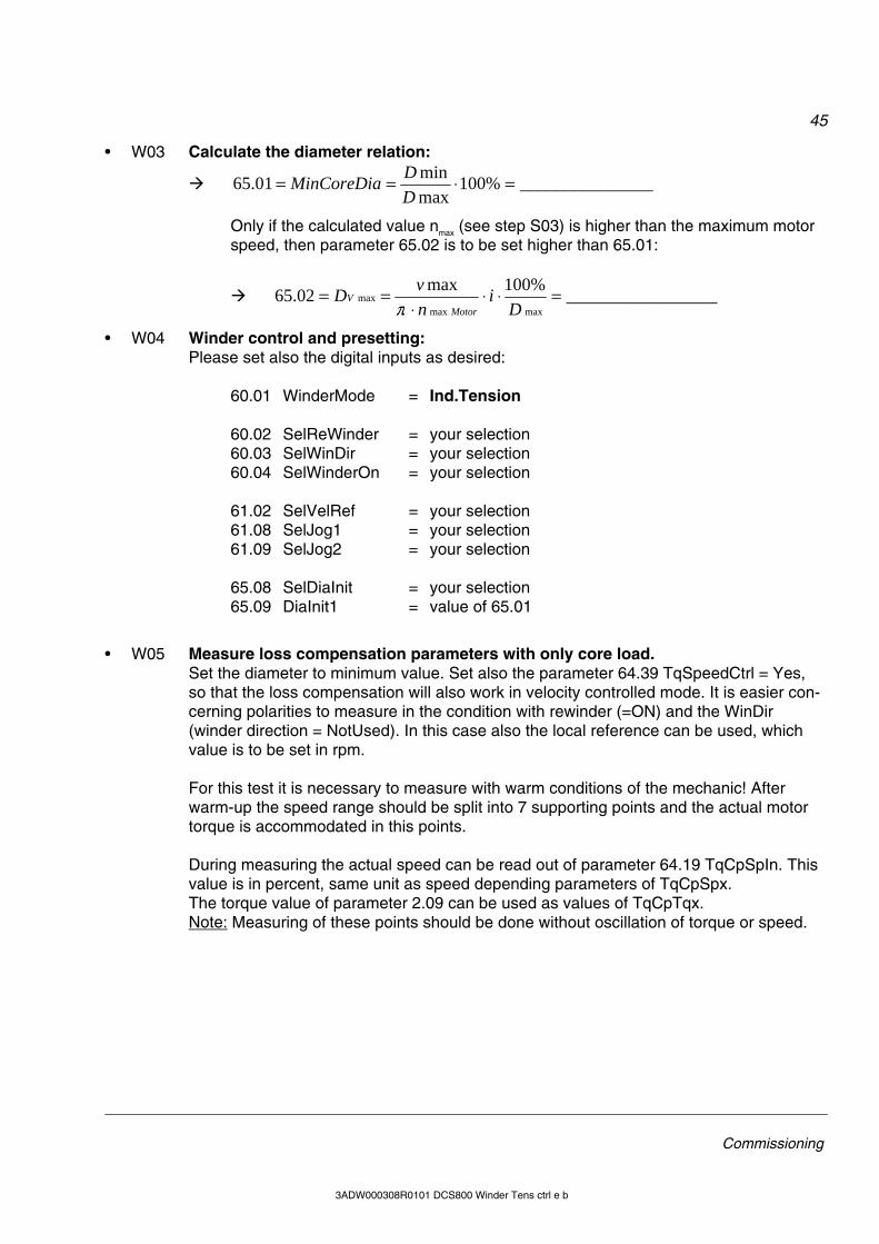
45
Commissioning
3ADW000308R0101 DCS800 Winder Tens ctrl e b
• W03 Calculate the diameter relation:
_______________%100maxmin01.65 =⋅==
DDMinCoreDia
Only if the calculated value nmax (see step S03) is higher than the maximum motor speed, then parameter 65.02 is to be set higher than 65.01:
_________________%100max02.65maxmax
max =⋅⋅⋅
==D
invD
MotorV
π
• W04 Winder control and presetting: Please set also the digital inputs as desired: 60.01 WinderMode = Ind.Tension 60.02 SelReWinder = your selection 60.03 SelWinDir = your selection 60.04 SelWinderOn = your selection 61.02 SelVelRef = your selection 61.08 SelJog1 = your selection 61.09 SelJog2 = your selection 65.08 SelDiaInit = your selection 65.09 DiaInit1 = value of 65.01
• W05 Measure loss compensation parameters with only core load. Set the diameter to minimum value. Set also the parameter 64.39 TqSpeedCtrl = Yes, so that the loss compensation will also work in velocity controlled mode. It is easier con-cerning polarities to measure in the condition with rewinder (=ON) and the WinDir (winder direction = NotUsed). In this case also the local reference can be used, which value is to be set in rpm. For this test it is necessary to measure with warm conditions of the mechanic! After warm-up the speed range should be split into 7 supporting points and the actual motor torque is accommodated in this points. During measuring the actual speed can be read out of parameter 64.19 TqCpSpIn. This value is in percent, same unit as speed depending parameters of TqCpSpx. The torque value of parameter 2.09 can be used as values of TqCpTqx. Note: Measuring of these points should be done without oscillation of torque or speed.
46
Commissioning
3ADW000308R0201 DCS800 Winder Tens ctrl e b
The following values show the speed depending supporting points as default.
• 64.32 TqCpSp6 = 100,0% 64.33 TqCpTq6 = measured value
• 64.30 TqCpSp5 = 80,0% 64.31 TqCpTq5 = measured value
• 64.28 TqCpSp4 = 60,0% 64.29 TqCpTq4 = measured value
• 64.26 TqCpSp3 = 40,0% 64.27 TqCpTq3 = measured value
• 64.24 TqCpSp2 = 20,0% 64.25 TqCpTq2 = measured value
• 64.22 TqCpSp1 = 0,5% 64.23 TqCpTq1 = measured value
• 64.20 TqCpSp0 = 0,0% 64.21 TqCpTq0 = measured value (adhesion)
• W06 Acceleration: Derivation of velocity reference
The derivative signal can either created out of the velocity reference or can be taken as value depending on the superior ramp generator.
• … either derivative velocity signal The output ScaledVal of the velocity reference function block is the default input source. This assumes that the winder drive gets a ramped reference. During commissioning this ramped reference is mostly not free available. So the ac-celerating adjustment can also be done by using the DCS800 internal ramp genera-tor, if the shortest ramp time is known.
• Therefore set the selector via parameter 64.02 SelDeriIn to “Spec 2”, which con-nects the input to the signal SpeedRampOut (2.32).
• Please take care: For the next steps the minimum diameter has continuously be set. If no other values known, start with 64.03 AccFilT= 40ms and 64.04 AccTD = 100ms.
• Let the reference ramp up and down. Observe the wave form of output 64.20 AccFiltOut. If necessary do an adaptation with the parameters 64.03 and 64.04.
• For increasing the amplitude to the necessary value of ±30000 as highest value for the shortest ramp time, please use the parameters 64.05 AccMult and 64.06 AccDiv for adaptation. Take care that a regular value will not generate a value higher than ±30000.
• … ramp depending value By using a derivative value of a superior ramp generator set the following parame-ters: 64.02 SelDeriIn = ? select the input 64.04 AccTD = 0 function block will not do a derivation
• For increasing the amplitude to the necessary value of ±30000 as highest value for the shortest ramp time, please use the parameters 64.05 AccMult and 64.06 AccDiv for adaptation. Take care that a regular value will not generate a value higher than ±30000.
47
Commissioning
3ADW000308R0101 DCS800 Winder Tens ctrl e b
• W07 Accelerating compensation of winder mechanics Let the reference ramp up and down. Observe the output of speed controller, parameter 2.09, and write the values of ramping up and down into parameter 64.13 and 64.14: 64.13 AccMecPosSca = value of 2.09 during ramping up 64.14 AccMecNegSca = value of 2.09 during ramping down. Stop and switch off the winder drive.
• W08 Big coil needed For the next steps the coil (reel) with the maximum values of this winder drive has to be mounted. If the values (diameter, width) is lower, than please set the correct value into the pa-rameters. 64.17 AccCoiWidth = 100% or the real mounted percental width 65.09 DiaInit1 = 100% or the real mounted percental diameter Take care that the new diameter init value is set and take care that the web is fixed, be-cause the coil will turn up to maximum line speed.
• W09 Tuning of speed controller with maximum diameter If parameter 64.39 TqSpeedCtrl is set to No, the adjustment can be done without losses and mechanical accelerating torque. Let the winder run and increase carefully the speed up to the maximum line speed, not the maximum motor speed. Measure the line speed on the surface of the coil. Adjust the speed controller, which works as line speed controller. The following values are used: 61.16 KpDiaMax = value of proportional part of controller 61.17 TnDiaMax = value of integral part of controller Please note:
• The filter of actual speed is increased depending on diameter. • The controller with this settings are used while e.g. jogging and E-Stop.
• W10 Set parameter 61.18 KpWinMode The value of this parameter is only responsible during window control, which is activated while running in tension controlled mode. A preset value could be: 61.18 KpWinMode = 5 times of value of 61.16 KpDiaMax
• W11 Accelerating compensation of the coil The diameter and the width are still to be set to the current values as described in point W08. Set also parameter 64.39 TqSpeedCtrl to Yes.
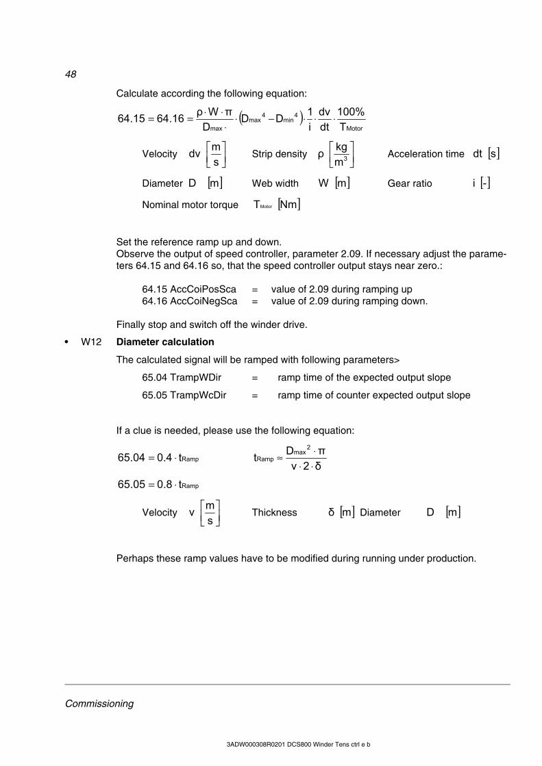
48
Commissioning
3ADW000308R0201 DCS800 Winder Tens ctrl e b
Calculate according the following equation:
( )Motor
4min
4max
max T100%
dtdv
i1DD
DπWρ64.1664.15 ⋅⋅⋅−⋅⋅
⋅⋅==
Velocity ⎥⎦⎤
⎢⎣⎡
sm dv Strip density ⎥⎦
⎤⎢⎣⎡
3mkg ρ Acceleration time [ ]s dt
Diameter [ ]m D Web width [ ]m W Gear ratio [ ]- i
Nominal motor torque [ ]Nm TMotor
Set the reference ramp up and down. Observe the output of speed controller, parameter 2.09. If necessary adjust the parame-ters 64.15 and 64.16 so, that the speed controller output stays near zero.: 64.15 AccCoiPosSca = value of 2.09 during ramping up 64.16 AccCoiNegSca = value of 2.09 during ramping down. Finally stop and switch off the winder drive.
• W12 Diameter calculation
The calculated signal will be ramped with following parameters>
65.04 TrampWDir = ramp time of the expected output slope
65.05 TrampWcDir = ramp time of counter expected output slope
If a clue is needed, please use the following equation:
Rampt0.465.04 ⋅= δ2vπDt
2max
Ramp⋅⋅⋅≈
Rampt0.865.05 ⋅=
Velocity ⎥⎦⎤
⎢⎣⎡
sm v Thickness [ ]m δ Diameter [ ]m D
Perhaps these ramp values have to be modified during running under production.
49
Commissioning
3ADW000308R0101 DCS800 Winder Tens ctrl e b
• W13 Torque scaling
The tension reference (also called tension set point) has to be scaled. This is done with
parameter 66.03 TorqueScale
Motor
maxmax
T100%
i2DF66.03 ⋅⋅⋅=
Tension [ ]N F Diameter [ ]m D Gear ratio [ ]- i
Nominal motor torque [ ]Nm TMotor
• W14 Set back parameters A few parameters are set to other values for supporting this commissioning. Set them back: 64.02 SelDeriIn = Spec 1 (default) or as desired; see W06 64.39 TqSpeedCtrl = No (default) or as desired
• W15 Further commissioning Up to now it has been a basic commissioning. Further settings are to be done yet, if desired.
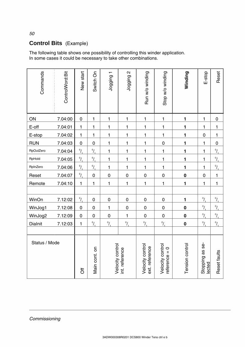
50
Commissioning
3ADW000308R0201 DCS800 Winder Tens ctrl e b
Control Bits (Example) The following table shows one possibility of controlling this winder application. In some cases it could be necessary to take other combinations.
Com
man
ds
Con
trol
Wor
d:B
it
New
sta
rt
Sw
itch
On
Jogg
ing
1
Jogg
ing
2
Run
w/o
win
ding
Sto
p w
/o w
indi
ng
Win
din
g
E-s
top
Res
et
ON 7.04:00 0 1 1 1 1 1 1 1 0
E-off 7.04:01 1 1 1 1 1 1 1 1 1
E-stop 7.04:02 1 1 1 1 1 1 1 0 1
RUN 7.04:03 0 0 1 1 1 0 1 1 0
RpOutZero 7.04:04 0/1 0/1 1 1 1 1 1 1 0/1
RpHold 7.04:05 0/1 0/1 1 1 1 1 1 1 0/1
RpInZero 7.04:06 0/1 0/1 1 1 1 1 1 1 0/1
Reset 7.04:07 0/1 0 0 0 0 0 0 0 1
Remote 7.04:10 1 1 1 1 1 1 1 1 1
WinOn 7.12:02 0/1 0 0 0 0 0 1 0/1 0/1
WinJog1 7.12:08 0 0 1 0 0 0 0 0/1 0/1
WinJog2 7.12:09 0 0 0 1 0 0 0 0/1 0/1
DiaInit 7.12:03 1 0/1 0/1
0/1 0/1
0/1 0 0/1 0/1
Status / Mode
Off
Mai
n co
nt. o
n
Vel
ocity
con
trol
in
t. re
fere
nce
Vel
ocity
con
trol
ex
t. re
fere
nce
Vel
ocity
con
trol
re
fere
nce
= 0
Ten
sion
con
trol
Sto
ppin
g as
se-
lect
ed
Res
et fa
ults
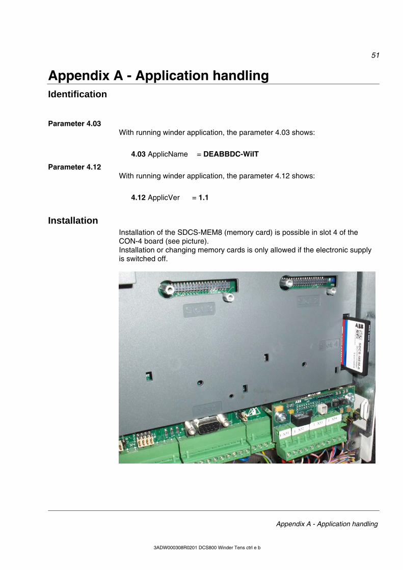
51
Appendix A - Application handling
3ADW000308R0201 DCS800 Winder Tens ctrl e b
Appendix A - Application handling Identification Parameter 4.03 With running winder application, the parameter 4.03 shows:
4.03 ApplicName = DEABBDC-WiIT
Parameter 4.12 With running winder application, the parameter 4.12 shows:
4.12 ApplicVer = 1.1
Installation Installation of the SDCS-MEM8 (memory card) is possible in slot 4 of the
CON-4 board (see picture). Installation or changing memory cards is only allowed if the electronic supply is switched off.

52
Appendix A - Application handling
3ADW000308R0201 DCS800 Winder Tens ctrl e b
Enable / disable application The application can be enabled and disabled by using parameter 16.06:
• Enable application (activate application program) • Disable application (deactivate application program)
After the activation of the memory card, all application parameters will be visi-ble and active.

ABB Automation Products Wallstadter Straße 59 68526 Ladenburg • Germany Tel: +49 (0) 62 03-71-0 Fax: +49 (0) 62 03-71-7609 www.abb.com/motors&drives
*308R0201A8210000**308R0201A8210000*
Iden
t. N
o.: 3
AD
W00
0308
R02
01 R
ev. B
05
_200
8