Embed Size (px)
DESCRIPTION
User guide for the DDW-120 ethernet extender
Citation preview
Industrial EthernetSHDSL Extender
www.westermo.com
©W
este
rmo T
elei
ndus
tri A
BUser Guide
6621-2212
DDW-120

2 6621-2212
Legal informationThe contents of this document are provided “as is”. Except as required by applicable law, no warranties of any kind, either express or implied, including, but not limited to, the implied warranties of merchantability and fitness for a particular purpose, are made in relation to the accuracy and reliability or contents of this document. Westermo reserves the right to revise this document or withdraw it at any time without prior notice.
Under no circumstances shall Westermo be responsible for any loss of data or income or any special, incidental, and consequential or indirect damages howsoever caused.
More information about Westermo can be found at the following Internet address:
http://www.westermo.com
36621-2212
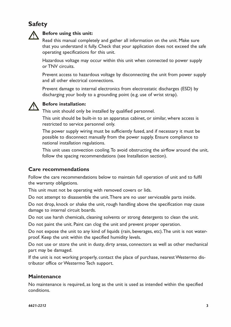
SafetyBefore using this unit:
Read this manual completely and gather all information on the unit. Make sure
that you understand it fully. Check that your application does not exceed the safe
operating specifications for this unit.
Hazardous voltage may occur within this unit when connected to power supply
or TNV circuits.
Prevent access to hazardous voltage by disconnecting the unit from power supply
and all other electrical connections.
Prevent damage to internal electronics from electrostatic discharges (ESD) by
discharging your body to a grounding point (e.g. use of wrist strap).
Before installation:
This unit should only be installed by qualified personnel.
This unit should be built-in to an apparatus cabinet, or similar, where access is
restricted to service personnel only.
The power supply wiring must be sufficiently fused, and if necessary it must be
possible to disconnect manually from the power supply. Ensure compliance to
national installation regulations.
This unit uses convection cooling. To avoid obstructing the airflow around the unit,
follow the spacing recommendations (see Installation section).
Care recommendationsFollow the care recommendations below to maintain full operation of unit and to fulfil
the warranty obligations.
This unit must not be operating with removed covers or lids.
Do not attempt to disassemble the unit. There are no user serviceable parts inside.
Do not drop, knock or shake the unit, rough handling above the specification may cause
damage to internal circuit boards.
Do not use harsh chemicals, cleaning solvents or strong detergents to clean the unit.
Do not paint the unit. Paint can clog the unit and prevent proper operation.
Do not expose the unit to any kind of liquids (rain, beverages, etc). The unit is not water-
proof. Keep the unit within the specified humidity levels.
Do not use or store the unit in dusty, dirty areas, connectors as well as other mechanical
part may be damaged.
If the unit is not working properly, contact the place of purchase, nearest Westermo dis-
tributor office or Westermo Tech support.
MaintenanceNo maintenance is required, as long as the unit is used as intended within the specified
conditions.
!
!
4 6621-2212
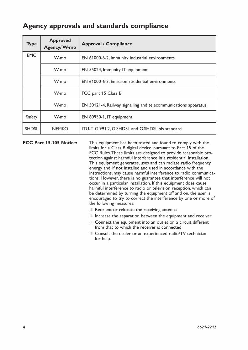
Agency approvals and standards compliance
FCC Part 15.105 Notice: This equipment has been tested and found to comply with the limits for a Class B digital device, pursuant to Part 15 of the FCC Rules. These limits are designed to provide reasonable pro-tection against harmful interference in a residential installation. This equip ment generates, uses and can radiate radio frequency energy and, if not installed and used in accordance with the instructions, may cause harmful interference to radio communica-tions. However, there is no guarantee that interference will not occur in a particular installation. If this equipment does cause harmful interference to radio or television reception, which can be determined by turning the equipment off and on, the user is encouraged to try to correct the interference by one or more of the following measures:
… Reorient or relocate the receiving antenna
… Increase the separation between the equipment and receiver
… Connect the equipment into an outlet on a circuit different from that to which the receiver is connected
… Consult the dealer or an experienced radio/TV technician for help.
TypeApproved
Agency/ W-moApproval / Compliance
EMCW-mo EN 61000-6-2, Immunity industrial environments
W-mo EN 55024, Immunity IT equipment
W-mo EN 61000-6-3, Emission residential environments
W-mo FCC part 15 Class B
W-mo EN 50121-4, Railway signalling and telecommunications apparatus
Safety W-mo EN 60950-1, IT equipment
SHDSL NEMKO ITU-T G.991.2, G.SHDSL and G.SHDSL.bis standard
56621-2212
Westermo Teleindustri AB
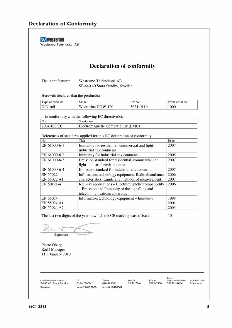
Declaration of conformity
Org.nr/
Postadress/Postal address Tel. Telefax Postgiro Bankgiro Corp. identity number Registered office
S-640 40 Stora Sundby 016-428000 016-428001 52 72 79-4 5671-5550 556361-2604 Eskilstuna
Sweden Int+46 16428000 Int+46 16428001
The manufacturer Westermo Teleindustri AB SE-640 40 Stora Sundby, Sweden
Herewith declares that the product(s)
Type of product Model Art no From serial no.
DIN-rail Wolverine DDW-120 3621-0110 1000 is in conformity with the following EC directive(s). No Short name
2004/108/EC Electromagnetic Compatibility (EMC) References of standards applied for this EC declaration of conformity. No Title Issue
EN 61000-6-1 Immunity for residential, commercial and light-industrial environments
2007
EN 61000-6-2 Immunity for industrial environments 2005 EN 61000-6-3 Emission standard for residential, commercial and
light-industrial environments 2007
EN 61000-6-4 Emission standard for industrial environments 2007 EN 55022 EN 55022 A1
Information technology equipment. Radio disturbance characteristics. Limits and methods of measurement.
2006 2007
EN 50121-4 Railway applications – Electromagnetic compatibility – Emission and Immunity of the signalling and telecommunications apparatus
2006
EN 55024 EN 55024 A1 EN 55024 A2
Information technology equipment – Immunity
1998 2001 2003
The last two digits of the year in which the CE marking was affixed: 10
Pierre Öberg R&D Manager 11th January 2010
Declaration of Conformity
6 6621-2212
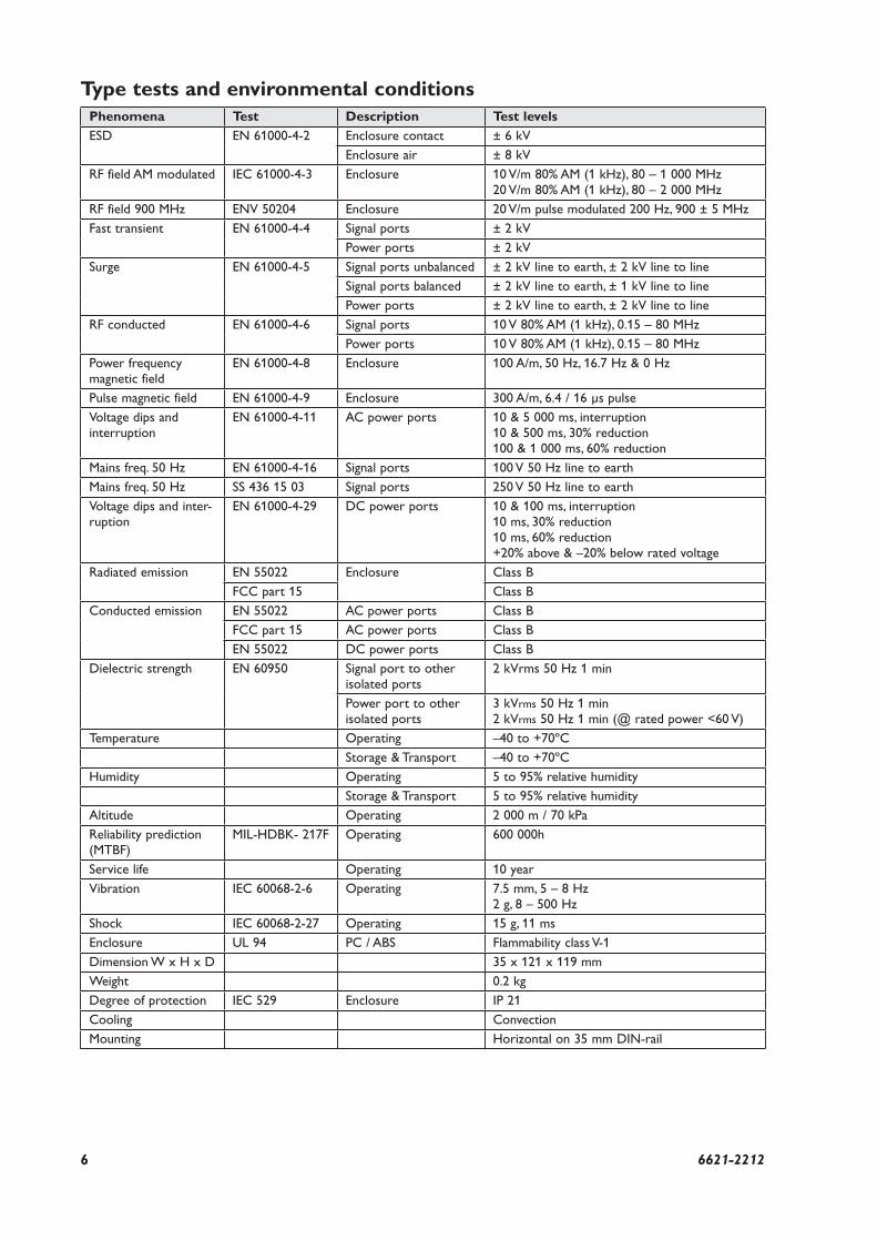
Type tests and environmental conditionsPhenomena Test Description Test levels
ESD EN 61000-4-2 Enclosure contact ± 6 kV
Enclosure air ± 8 kV
RF field AM modulated IEC 61000-4-3 Enclosure 10 V/m 80% AM (1 kHz), 80 – 1 000 MHz20 V/m 80% AM (1 kHz), 80 – 2 000 MHz
RF field 900 MHz ENV 50204 Enclosure 20 V/m pulse modulated 200 Hz, 900 ± 5 MHz
Fast transient EN 61000-4-4 Signal ports ± 2 kV
Power ports ± 2 kV
Surge EN 61000-4-5 Signal ports unbalanced ± 2 kV line to earth, ± 2 kV line to line
Signal ports balanced ± 2 kV line to earth, ± 1 kV line to line
Power ports ± 2 kV line to earth, ± 2 kV line to line
RF conducted EN 61000-4-6 Signal ports 10 V 80% AM (1 kHz), 0.15 – 80 MHz
Power ports 10 V 80% AM (1 kHz), 0.15 – 80 MHz
Power frequency magnetic field
EN 61000-4-8 Enclosure 100 A/m, 50 Hz, 16.7 Hz & 0 Hz
Pulse magnetic field EN 61000-4-9 Enclosure 300 A/m, 6.4 / 16 μs pulse
Voltage dips and interruption
EN 61000-4-11 AC power ports 10 & 5 000 ms, interruption10 & 500 ms, 30% reduction100 & 1 000 ms, 60% reduction
Mains freq. 50 Hz EN 61000-4-16 Signal ports 100 V 50 Hz line to earth
Mains freq. 50 Hz SS 436 15 03 Signal ports 250 V 50 Hz line to earth
Voltage dips and inter-ruption
EN 61000-4-29 DC power ports 10 & 100 ms, interruption10 ms, 30% reduction10 ms, 60% reduction+20% above & –20% below rated voltage
Radiated emission EN 55022 Enclosure Class B
FCC part 15 Class B
Conducted emission EN 55022 AC power ports Class B
FCC part 15 AC power ports Class B
EN 55022 DC power ports Class B
Dielectric strength EN 60950 Signal port to other isolated ports
2 kVrms 50 Hz 1 min
Power port to other isolated ports
3 kVrms 50 Hz 1 min2 kVrms 50 Hz 1 min (@ rated power <60 V)
Temperature Operating –40 to +70ºC
Storage & Transport –40 to +70ºC
Humidity Operating 5 to 95% relative humidity
Storage & Transport 5 to 95% relative humidity
Altitude Operating 2 000 m / 70 kPa
Reliability prediction (MTBF)
MIL-HDBK- 217F Operating 600 000h
Service life Operating 10 year
Vibration IEC 60068-2-6 Operating 7.5 mm, 5 – 8 Hz 2 g, 8 – 500 Hz
Shock IEC 60068-2-27 Operating 15 g, 11 ms
Enclosure UL 94 PC / ABS Flammability class V-1
Dimension W x H x D 35 x 121 x 119 mm
Weight 0.2 kg
Degree of protection IEC 529 Enclosure IP 21
Cooling Convection
Mounting Horizontal on 35 mm DIN-rail
76621-2212
Description
Functional descriptionThe DDW-120 Ethernet Extender is the ideal solution for extending your Ethernet
network over copper cables where in the past the only option would have been fibre.
At shorter range the transfer rate will be as fast as 15.3 Mbit/s in both directions.
Depending on the quality of the cables distances up to 15 km are possible.
DDW-120 is transparent for multicast addressing, VLAN packets, VPN pass-through for
IPSec and for protocols like MODBUS/tcp and Profinet. The Link Fault Forward (LFF)
functionality in DDW-120 forwards information about the Ethernet link status, this is
sent over the SHDSL link between two DDW-120 units. In many applications it is a
requirement to disconnect the link on the other side of the SHDSL link if the primary
Ethernet link goes down.
The units will auto negotiate the transmission speed but can also be forced to choose a
slower (more reliable) or faster (less reliable) data rate.
DDW-120 can be used in point-to-point applications or as start and termination unit
together with DDW-22x in a daisy-chain application.
Description of used nomenclature:
Noise margin:
The margin between signal and noise (dB)
CO/CPE:
CO (Central Office) answering central unit, the CO configures the CPE when establish-
ing a connection. CPE (Customer Premises Equipment) is the unit that initiates the con-
nection.
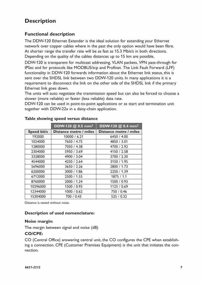
Table showing speed versus distance
DDW-120 @ 0.5 mm2 DDW-120 @ 0.4 mm2
Speed bit/s Distance metre / miles Distance metre / miles192000 10000 / 6.21 6450 / 4.00
1024000 7650 / 4.75 4850 / 3.01
1280000 7050 / 4.38 4700 / 2.92
2304000 5950 / 3.69 4150 / 2.58
3328000 4900 / 3.04 3700 / 2.30
4544000 4250 / 2.64 3150 / 1.95
5696000 3650 / 2.26 2800 / 1.73
6200000 3000 / 1.86 2250 / 1.39
6712000 2500 / 1.55 1875 / 1.1
8760000 2000 / 1.24 1500 / 0.93
10296000 1500 / 0.93 1125 / 0.69
12344000 1000 / 0.62 750 / 0.46
15304000 700 / 0.43 525 / 0.32
Distance is tested without noise.
8 6621-2212
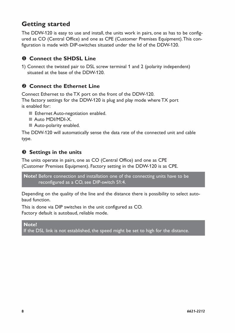
Getting startedThe DDW-120 is easy to use and install, the units work in pairs, one as has to be config-
ured as CO (Central Office) and one as CPE (Customer Premises Equipment). This con-
figuration is made with DIP-switches situated under the lid of the DDW-120.
Connect the SHDSL Line1) Connect the twisted pair to DSL screw terminal 1 and 2 (polarity independent)
situated at the base of the DDW-120.
Connect the Ethernet LineConnect Ethernet to the TX port on the front of the DDW-120.
The factory settings for the DDW-120 is plug and play mode where TX port
is enabled for:
… Ethernet Auto-negotiation enabled.
… Auto MDI/MDI-X.
… Auto-polarity enabled.
The DDW-120 will automatically sense the data rate of the connected unit and cable
type.
Settings in the unitsThe units operate in pairs, one as CO (Central Office) and one as CPE
(Customer Premises Equipment). Factory setting in the DDW-120 is as CPE.
Depending on the quality of the line and the distance there is possibility to select auto-
baud function.
This is done via DIP switches in the unit configured as CO.
Factory default is autobaud, reliable mode.
Note! Before connection and installation one of the connecting units have to be
reconfigured as a CO, see DIP-switch S1:4.
Note! If the DSL link is not established, the speed might be set to high for the distance.
96621-2212
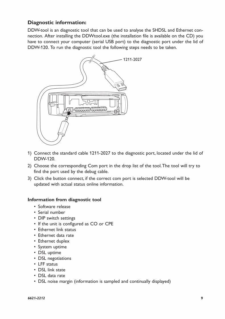
Diagnostic information:DDW-tool is an diagnostic tool that can be used to analyse the SHDSL and Ethernet con-
nection. After installing the DDWtool.exe (the installation file is available on the CD) you
have to connect your computer (serial USB port) to the diagnostic port under the lid of
DDW-120. To run the diagnostic tool the following steps needs to be taken.
1) Connect the standard cable 1211-2027 to the diagnostic port, located under the lid of
DDW-120.
2) Choose the corresponding Com port in the drop list of the tool. The tool will try to
find the port used by the debug cable.
3) Click the button connect, if the correct com port is selected DDW-tool will be
updated with actual status online information.
Information from diagnostic tool
• Software release
• Serial number
• DIP switch settings
• If the unit is configured as CO or CPE
• Ethernet link status
• Ethernet data rate
• Ethernet duplex
• System uptime
• DSL uptime
• DSL negotiations
• LFF status
• DSL link state
• DSL data rate
• DSL noise margin (information is sampled and continually displayed)
1211-2027
10 6621-2212
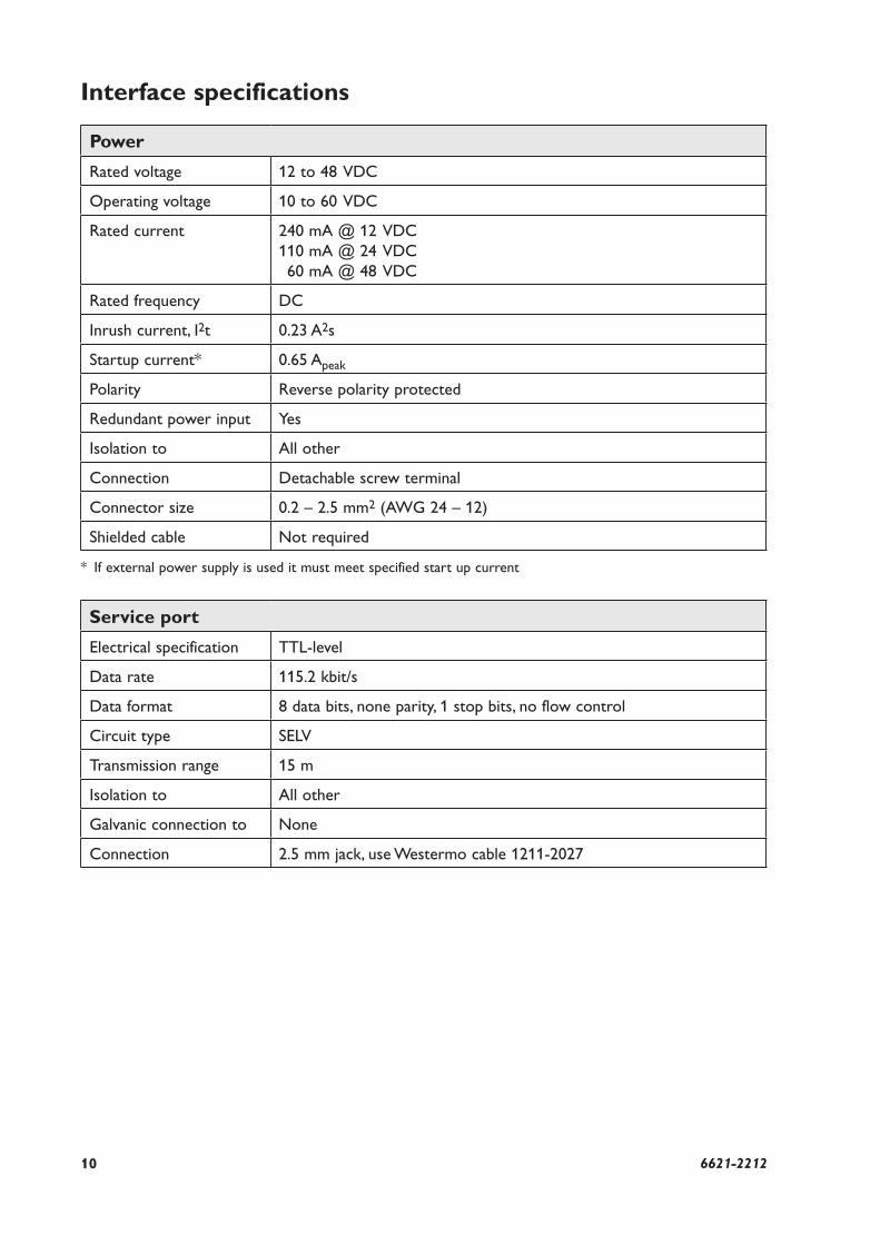
Interface specifications
Power
Rated voltage 12 to 48 VDC
Operating voltage 10 to 60 VDC
Rated current 240 mA @ 12 VDC
110 mA @ 24 VDC
60 mA @ 48 VDC
Rated frequency DC
Inrush current, I2t 0.23 A2s
Startup current* 0.65 Apeak
Polarity Reverse polarity protected
Redundant power input Yes
Isolation to All other
Connection Detachable screw terminal
Connector size 0.2 – 2.5 mm2 (AWG 24 – 12)
Shielded cable Not required
* If external power supply is used it must meet specified start up current
Service port
Electrical specification TTL-level
Data rate 115.2 kbit/s
Data format 8 data bits, none parity, 1 stop bits, no flow control
Circuit type SELV
Transmission range 15 m
Isolation to All other
Galvanic connection to None
Connection 2.5 mm jack, use Westermo cable 1211-2027
116621-2212
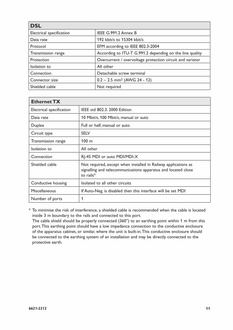
* To minimise the risk of interference, a shielded cable is recommended when the cable is located
inside 3 m boundary to the rails and connected to this port.
The cable shield should be properly connected (360°) to an earthing point within 1 m from this
port. This earthing point should have a low impedance connection to the conductive enclosure
of the apparatus cabinet, or similar, where the unit is built-in. This conductive enclosure should
be connected to the earthing system of an installation and may be directly connected to the
protective earth.
Ethernet TX
Electrical specification IEEE std 802.3. 2000 Edition
Data rate 10 Mbit/s, 100 Mbit/s, manual or auto
Duplex Full or half, manual or auto
Circuit type SELV
Transmission range 100 m
Isolation to All other
Connection RJ-45 MDI or auto MDI/MDI-X
Shielded cable Not required, except when installed in Railway applications as
signalling and telecommunications apparatus and located close
to rails*
Conductive housing Isolated to all other circuits
Miscellaneous If Auto-Neg. is disabled then this interface will be set MDI
Number of ports 1
DSL Electrical specification IEEE G.991.2 Annex B
Data rate 192 kbit/s to 15304 kbit/s
Protocol EFM according to IEEE 802.3-2004
Transmission range According to ITU-T G.991.2 depending on the line quality
Protection Overcurrent / overvoltage protection circuit and varistor
Isolation to All other
Connection Detachable screw terminal
Connector size 0.2 – 2.5 mm2 (AWG 24 - 12)
Shielded cable Not required
12 6621-2212
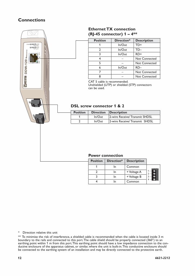
Connections
* Direction relative this unit
** To minimise the risk of interference, a shielded cable is recommended when the cable is located inside 3 m boundary to the rails and connected to this port. The cable shield should be properly connected (360°) to an earthing point within 1 m from this port. This earthing point should have a low impedance connection to the con-ductive enclosure of the apparatus cabinet, or similar, where the unit is built-in. This conductive enclosure should be connected to the earthing system of an installation and may be directly connected to the protective earth.
DSL screw connector 1 & 2
Position Direction Description1 In/Out 2-wire Receive/ Transmit SHDSL
2 In/Out 2-wire Receive/ Transmit SHDSL
Ethernet TX connection (RJ-45 connector) 1 – 4**
Position Direction* Description1 In/Out TD+
2 In/Out TD–
3 In/Out RD+
4 – Not Connected
5 – Not Connected
6 In/Out RD–
7 – Not Connected
8 – Not Connected
CAT 5 cable is recommended.Unshielded (UTP) or shielded (STP) connectors can be used.
Power connection Position Direction* Description
1 In Common
2 In + Voltage A
3 In + Voltage B
4 In Common
1
2
3
4
12
34
12
136621-2212
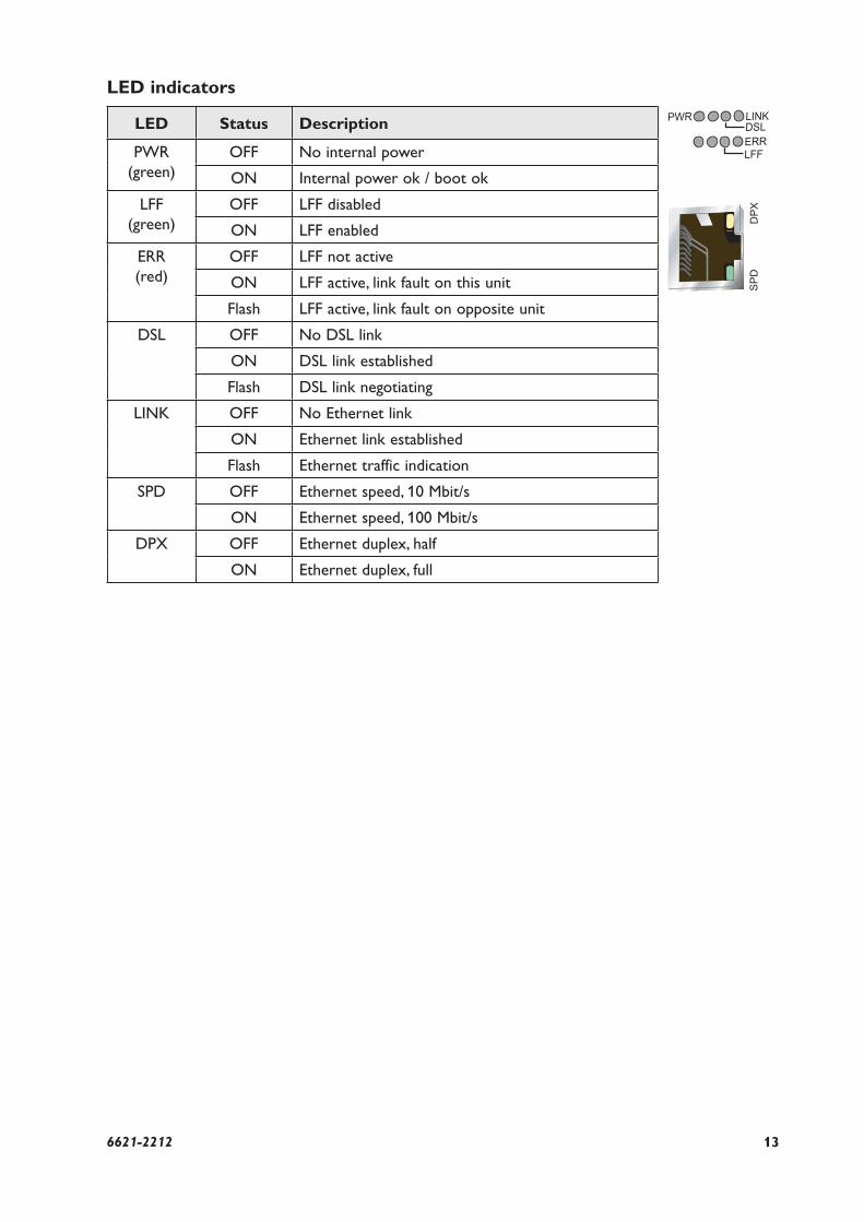
LED indicators
LED Status Description
PWR
(green)
OFF No internal power
ON Internal power ok / boot ok
LFF
(green)
OFF LFF disabled
ON LFF enabled
ERR
(red)
OFF LFF not active
ON LFF active, link fault on this unit
Flash LFF active, link fault on opposite unit
DSL OFF No DSL link
ON DSL link established
Flash DSL link negotiating
LINK OFF No Ethernet link
ON Ethernet link established
Flash Ethernet traffic indication
SPD OFF Ethernet speed, 10 Mbit/s
ON Ethernet speed, 100 Mbit/s
DPX OFF Ethernet duplex, half
ON Ethernet duplex, full
14 6621-2212
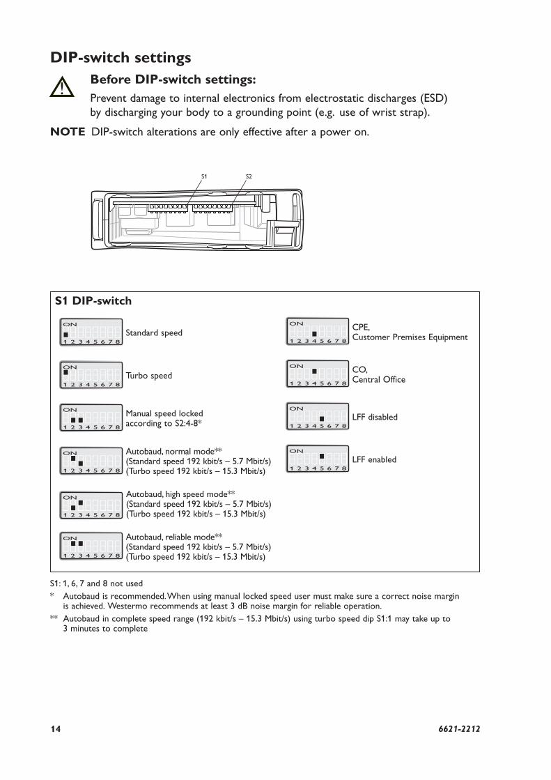
DIP-switch settingsBefore DIP-switch settings:Prevent damage to internal electronics from electrostatic discharges (ESD)
by discharging your body to a grounding point (e.g. use of wrist strap).
NOTE DIP-switch alterations are only effective after a power on.
!
S2S1
S1 DIP-switch
S1: 1, 6, 7 and 8 not used
* Autobaud is recommended. When using manual locked speed user must make sure a correct noise margin is achieved. Westermo recommends at least 3 dB noise margin for reliable operation.
** Autobaud in complete speed range (192 kbit/s – 15.3 Mbit/s) using turbo speed dip S1:1 may take up to 3 minutes to complete
ON
1 2 3 4 5 6 7 8
Autobaud, normal mode**(Standard speed 192 kbit/s – 5.7 Mbit/s)(Turbo speed 192 kbit/s – 15.3 Mbit/s)
ON
1 2 3 4 5 6 7 8
Turbo speed
ON
1 2 3 4 5 6 7 8
Standard speed
ON
1 2 3 4 5 6 7 8
Autobaud, high speed mode**(Standard speed 192 kbit/s – 5.7 Mbit/s)(Turbo speed 192 kbit/s – 15.3 Mbit/s)
ON
1 2 3 4 5 6 7 8
Autobaud, reliable mode**(Standard speed 192 kbit/s – 5.7 Mbit/s)(Turbo speed 192 kbit/s – 15.3 Mbit/s)
ON
1 2 3 4 5 6 7 8
Manual speed locked according to S2:4-8*
ON
1 2 3 4 5 6 7 8
CPE, Customer Premises Equipment
ON
1 2 3 4 5 6 7 8
CO, Central Office
ON
1 2 3 4 5 6 7 8
LFF disabled
ON
1 2 3 4 5 6 7 8
LFF enabled
156621-2212
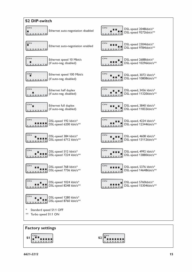
S2 DIP-switch
ON
1 2 3 4 5 6 7 8
Ethernet auto-negotiation disabled
ON
1 2 3 4 5 6 7 8
Ethernet auto-negotiation enabled
ON
1 2 3 4 5 6 7 8
Ethernet speed 10 Mbit/s (if auto-neg. disabled)
ON
1 2 3 4 5 6 7 8
Ethernet speed 100 Mbit/s
(if auto-neg. disabled)
ON
1 2 3 4 5 6 7 8
Ethernet half duplex (if auto-neg. disabled)
ON
1 2 3 4 5 6 7 8
Ethernet full duplex (if auto-neg. disabled)
ON
1 2 3 4 5 6 7 8
DSL-speed 192 kbit/s*DSL-speed 6200 kbit/s**
ON
1 2 3 4 5 6 7 8
DSL-speed 384 kbit/s* DSL-speed 6712 kbit/s**
ON
1 2 3 4 5 6 7 8
DSL-speed 512 kbit/s* DSL-speed 7224 kbit/s**
ON
1 2 3 4 5 6 7 8
DSL-speed 768 kbit/s* DSL-speed 7736 kbit/s**
ON
1 2 3 4 5 6 7 8
DSL-speed 1024 kbit/s* DSL-speed 8248 kbit/s**
ON
1 2 3 4 5 6 7 8
DSL-speed 1280 kbit/s*DSL-speed 8760 kbit/s**
Factory settings
ON
1 2 3 4 5 6 7 8
S1ON
1 2 3 4 5 6 7 8
S2
ON
1 2 3 4 5 6 7 8
DSL-speed 2688kbit/s*DSL-speed 10296kbit/s**
ON
1 2 3 4 5 6 7 8
DSL-speed, 3072 kbit/s*DSL-speed 10808kbit/s**
ON
1 2 3 4 5 6 7 8
DSL-speed, 3456 kbit/s*DSL-speed 11320kbit/s**
ON
1 2 3 4 5 6 7 8
DSL-speed 2048kbit/s*DSL-speed 9272kbit/s**
ON
1 2 3 4 5 6 7 8
DSL-speed, 3840 kbit/s*DSL-speed 11832kbit/s**
ON
1 2 3 4 5 6 7 8
DSL-speed 2304kbit/s*DSL-speed 9784kbit/s**
ON
1 2 3 4 5 6 7 8
DSL-speed, 4224 kbit/s*DSL-speed 12344kbit/s**
ON
1 2 3 4 5 6 7 8
DSL-speed, 4608 kbit/s*DSL-speed 13112kbit/s**
ON
1 2 3 4 5 6 7 8
DSL-speed, 4992 kbit/s*DSL-speed 13880kbit/s**
ON
1 2 3 4 5 6 7 8
DSL-speed, 5376 kbit/s*DSL-speed 14648kbit/s**
ON
1 2 3 4 5 6 7 8
DSL-speed 5760kbit/s*DSL-speed 15304kbit/s**
* Standard speed S1:1 OFF
** Turbo speed S1:1 ON
16 6621-2212
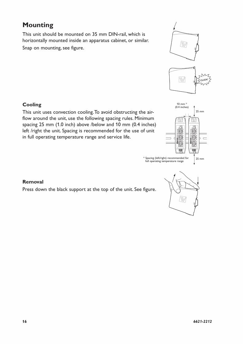
Cooling
This unit uses convection cooling. To avoid obstructing the air-
flow around the unit, use the following spacing rules. Minimum
spacing 25 mm (1.0 inch) above /below and 10 mm (0.4 inches)
left /right the unit. Spacing is recommended for the use of unit
in full operating temperature range and service life.
MountingThis unit should be mounted on 35 mm DIN-rail, which is
horizontally mounted inside an apparatus cabinet, or similar.
Snap on mounting, see figure.
CLICK!
Removal
Press down the black support at the top of the unit. See figure.
10 mm *(0.4 inches)
25 mm
25 mm* Spacing (left/right) recommended for full operating temperature range


RE
V.A
662
1-22
12
2009-1
1 W
est
erm
o T
ele
indust
ri A
B, S
weden
Westermo Teleindustri AB • SE-640 40 Stora Sundby, Sweden
Phone +46 16 42 80 00 Fax +46 16 42 80 01
E-mail: [email protected]
Westermo Web site: www.westermo.com
Westermo Teleindustri AB have distributors in several countries, contact us for further information.
Westermo Data Communications AB
Svalgången 1
SE-724 81 Västerås
Phone: +46 (0)21 548 08 00 • Fax: +46 (0)21 35 18 50
Westermo Data Communications Ltd
Talisman Business Centre • Duncan Road
Park Gate, Southampton • SO31 7GA
Phone: +44(0)1489 580-585 • Fax.:+44(0)1489 580586
E-Mail: [email protected]
Westermo Data Communications GmbH
Goethestraße 67, 68753 Waghäusel
Tel.: +49(0)7254-95400-0 • Fax.:+49(0)7254-95400-9
E-Mail: [email protected]
Westermo Data Communications S.A.R.L.
9 Chemin de Chilly 91160 CHAMPLAN
Tél : +33 1 69 10 21 00 • Fax : +33 1 69 10 21 01
E-mail : [email protected]
Westermo Data Communications Pte Ltd
2 Soon Wing Road #08-05
Soon Wing Industrial Building
Singapore 347893
Phone +65 6743 9801 • Fax +65 6745 0670
E-mail: [email protected]
Subsidiaries