Embed Size (px)
Citation preview
Deadlock-free wormhole routing algorithms for star graph topology
C.P. Ravikumar A.M.Goel
Indexing terms: Parallel processing, Routing algorithms, Routing optimisation
Abstract: For constructing massively parallel multicomputers with over 5000 processing nodes, the Star Graph topology is known to be better than the hypercube in terms of the average routing distance, the number of links per node, and the fault diameter. The authors present two deadlock-free algorithms for routing in Star Graph, assuming the Wormhole routing model. Both the algorithms use the concept of virtual channels introduced by Dally and Seitz. The first algorithm is non-optimal in terms of the average routing distance, but uses fewer virtual channels on the whole. The second algorithm is optimal in terms of routing performance, but requires a somewhat larger number of virtual channels per node.
1 Introduction
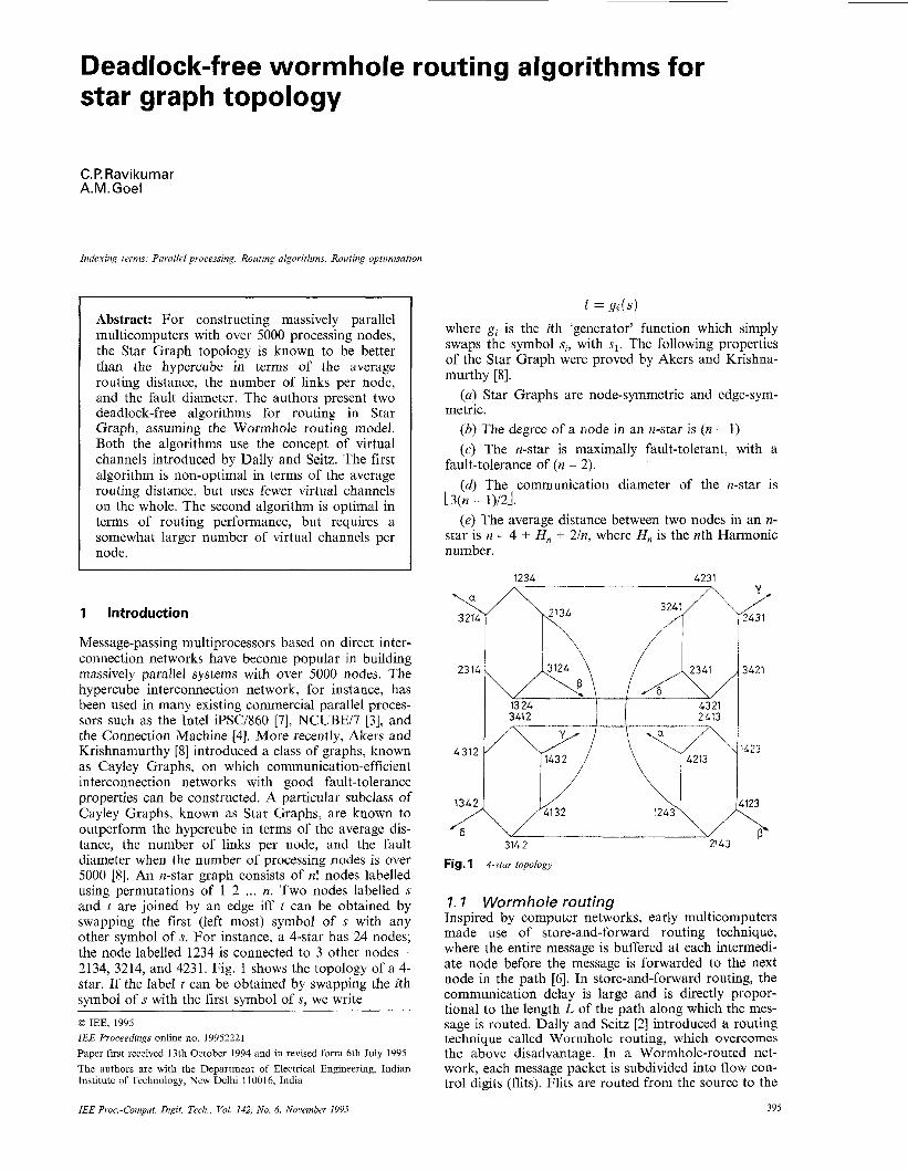
Message-passing multiprocessors based on direct inter- connection networks have become popular in building massively parallel systems with over 5000 nodes. The hypercube interconnection network, for instance, has been used in many existing commercial parallel proces- sors such as the Intel iPSCI860 [7], NCUBEI7 [3], and the Connection Machine [4]. More recently, Akers and Krishnamurthy [SI introduced a class of graphs, known as Cayley Graphs, on which communication-efficient interconnection networks with good fault-tolerance properties can be constructed. A particular subclass of Cayley Graphs, known as Star Graphs, are known to outperform the hypercube in terms of the average dis- tance, the number of links per node, and the fault diameter when the number of processing nodes is over 5000 [SI. An n-star graph consists of n! nodes labelled using permutations of 1 2 ... n. Two nodes labelled s and t are joined by an edge iff t can be obtained by swapping the first (left most) symbol of s with any other symbol of s. For instance, a 4-star has 24 nodes; the node labelled 1234 is connected to 3 other nodes - 2134, 3214, and 4231. Fig. 1 shows the topology of a 4- star. If the label t can be obtained by swapping the ith symbol of s with the first symbol of s, we write 0 IEE, 1995 IEE Proceedzngs online no 19952221 Paper first received 13th October 1994 and in revised form 6th July 1995 The authors are with the Department of Electrical Engineering, Indian Institute of Technology, New Delhi 110016, India
I! = ge (s)
where g, is the ith ‘generator’ function which simply swaps the symbol sz, with sl. The following properties of the Star Graph were proved by Akers and Krishna- murthy [SI.
(a) Star Graphs are node-symmetric and edge-sym- metric.
(b) The degree of a node in an n-star is (n - 1) (c) The n-star is mlaximally fault-tolerant, with a
fault-tolerance of (n - :!). (d) The communication diameter of the n-star is
L3(n - 1)12-l. (e) The average distance between two nodes in an n-
star is n - 4 f H, + 214 where H, is the nth Harmonic number.
1234 4231
Fig. 1 +star topology
I. I Wormhole routing Inspired by computer networks, early multicomputers made use of store-and-forward routing technique, where the entire message is buffered at each intermedi- ate node before the message is forwarded to the next node in the path [6]. 111 store-and-forward routing, the communication delay is large and is directly propor- tional to the length L of the path along which the mes- sage is routed. Dally and Seitz [2] introduced a routing technique called Wormhole routing, which overcomes the above disadvantage. In a Wormhole-routed net- work, each message packet is subdivided into flow con- trol digits (flits). Flits are routed from the source to the
395 IEE Proc-Comput. Digit. Tech., Vol. 142, No. 6, November 1995
destination in a pipelined fashion. Thus, the header flit can arrive at the destination even before the last flit of the message has left the source. All flits that belong to a message packet make use of the same set of commu- nication channels. In Wormhole routing, the communi- cation delay depends mainly on the bandwidth of the communication channels. Several commercial machines such as the Intel iPSC/860 and research prototypes such as the J-machine have adopted the Wormhole routing technique [6]. A disadvantage of Wormhole routing is that deadlocks can occur if special precau- tions are not taken to avoid deadlocks by carefully restructuring the routing algorithm [2]. Dally and Seitz presented deadlock-free routing algorithms fo c several network topologies such as the k-ary n-cube, the Shuf- fle-Exchange network, and the Cube-connected Cycles [2]. In this paper, we present two deadlock-free algo- rithms for the Star Graph topology.
node 123
‘231 1 1 ‘213
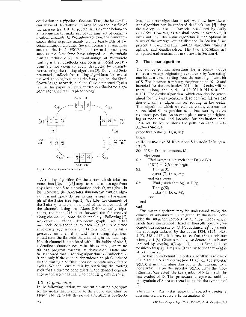
node 132 Fig.2 Deudlock sztuation in a 3-star
A routin algorithm for the n-star, which lakes no more than B 3(n - 1)/21 steps to route a message from any given node S to a destination node D, was given in [8]. However, the Akers-Krishnamurthy routing algo- rithm is not deadlock-free, as can be seen in the exam- ple of the 3-star (see Fig. 2). We label the channels of the 3-star c,, where s is the label of the source node of the channel. Using the Akers-Krishnamurthy algo- rithm, the node 213 must forward the flit received along channel ~ 1 2 3 onto the channel ~ 1 3 2 . Following [Z], we construct a channel dependence graph G which has one node corresponding to each channel. A directed edge exists from a node e, in G to a node cj if a flit is presently on channel e, and the routing algorithm would send the flit onto the channel c3 in the next step. If each channel is associated with a flit-buffer of size 3, a deadlock situation occurs in this example, where no flit can progress towards its destination. Dally and Seitz showed that a routing algorithm is deadlock-free if and only if the channel dependence graph G induced by the routing algorithm does not contain any directed cycles. We shall ensure this by restricting the routing such that a directed edge exists in the channel depend- ence graph from channel e, to channel cJ only if i > j .
1.2 Organisation In the following section, we present a routing algorithm for the n-star that is similar to the e-cube algorithm for Hypercube [2]. While the e-cube algorithm is deadlock-
396
free, our e-star algorithm is not; we show how the e- star algorithm can be rendered deadlock-free [5] using the concept of virtual channels introduced by Dally and Seitz. However, as we shall prove in Section 2, it turns out that the e-star algorithm is not optimal in terms of the average routing distance. In Section 3, we present a ‘cycle merging’ routing algorithm which is optimal and deadlock-free. The two algorithms are compared and conclusions are drawn in Section 4.
2 The e-star algorithm
The e-cube routing algorithm for a binary n-cube routes a message originating at source S by ‘correcting’ one bit at a time, starting from the most significant bit of S. For instance, a message originating at 10110 and intended for the destination 01101 in a 5-cube will be routed along the path 101 10-001 10-01 110-01 100- 01101. The e-cube algorithm, which can also be gener- alised for the k-ary n-cube, is deadlock-free [2]. We can derive a similar algorithm for routing in the n-star. This algorithm, which we call the e-star, corrects the source label S one position at a time, starting at the rightmost position. As an example, a message originat- ing at node 2341 and intended for destination node 1234 will be routed along the path 23414321-1324- 3124-2134-1234. procedure e-star (s, D, n, M); begin /* Route message M from node S to node D in an n- star *I SO: if S = D then consume M;
else begin Sl:
s2: T := g,(S);
Find largest i 5 n such that D(i) f S( i ) if S(l) = D(i) then begin
e-star (T, D, n, M); end else begin
F indj such that S(i) = D(i); T := gJ(S); e-star (T, D, n, M);
s3:
end end
end The e-star algorithm may be understood using the
concept of sub-stars in a star graph. In the n-star, con- sider the subgraph induced by all those nodes whose labels have the symbol i fixed in their jth position; we denote this subgraph by i,J. For instance, 243 represents the subgraph induced by the nodes 1324, 3124, 1423, 4123, 3421, 4321. It is easy to see that i,J is a sub-star whenj > 1 [8]. Given a node s, we denote the sub-star induced by keeping s(i) s(j + 1) ... s(n) fixed in their positions by tp(s3), 1 < j 2 n. It is easy to see that tp(sJ) is also a sub-star.
The basic idea behind the e-star algorithm is to check if the source S and destination D are on the sub-star tp(Dn); if not, the algorithm routes the message to a node which is on the sub-star v(Dn). Thus the algo- rithm has ‘corrected’ the last symbol of S to match the last symbol of D. This procedure is repeated, until all the symbols of S are corrected to match the symbols of D.
Theorem 1: The e-star algorithm correctly routes a message from a source S to destination D.
IEE PYOC -Cornput Digit Tech, Vol 142 No 6, November 1995
Proofl Given the label of the current node S and the destination node D, we define the function AS, D) to be the largest index i such that S( i ) f: D(i). When S = D, the functionfis defined to be 0. Suppose that the e- star algorithm routes the message from a node P to node Q. Then it is necessarily true that f (Q, D) I f(P, D), where D is the destination node. This may be seen by looking at Steps S1 and S3 in the above algorithm. Step S1 evaluates i = AS, D). If the algorithm takes Step S2, T is computed to be g,(S), in which case T(i) = D(i). Furthermore, the generator g, only changes the ith and 1st symbols of S. Therefore,AT, D) is at least one less than AS, D). If the algorithm takes Step S3, then f(T, D) = AS, D) since 1 < j < i. We now claim that whenever the e-star algorithm takes the Step S3, the following call of e-star will take Step S2. If T is the node to which Step S3 routes the message, then T(1) = Sei> = D(i). In the following call of e-star, T takes on the role of S, and hence S(l) = D(i), forcing the algo- rithm to execute Step S2. Further, Step S1 ensures that the algorithm will only stop forwarding the message if f(S, D) = 0. Hence the proof.
Theorem 2: The e-star algorithm takes no more than 2n - 3 steps to route a message on an n-star. The average routing distance achieved by the algorithm is 2n + 1 - 3H,. Proof: For correcting any position in the permutation corresponding to S, the e-star algorithm requires either no forwarding, a single forwarding step (Step S2), or two forwarding steps (Step S3 followed by Step S2). In the worst case, the algorithm takes 2 forwarding steps to correct each of the rightmost (n - 2) symbols, and then uses the Step S2 to correct the second symbol. Let T(n) be the average routing distance between any two nodes S and D on an n-star. Using the e-star algorithm, routing on an n-star is equivalent to correcting the rightmost position and then routing on the n - 1 sub- star. The symbol required to correct the rightmost posi- tion can be in any of the n positions of S with equal probability. If this symbol is in the first position, one forwarding step is required to correct the rightmost position. If the symbol is already in the rightmost posi- tion, no forwarding step is required to route to the sub- star. Finally, if the symbol is in any other positionj, 1 < j < n, two forwarding steps become necessary (Step S3 followed by Step S2). Hence, the following recur- rence relation results for T(n).
It is easy to see that the basis T(2) = 1/2. Solving the recurrence gives the required formula for T(n).
Theorem 3: The e-star algorithm of Fig. 3 is not dead- lock-free. Proof: For the routing pattern of Fig. 2, the e-star algorithm behaves identically as the Akers-Krishna- murthy algorithm, thereby inducing a directed cycle in the channel dependence graph.
2.1 Making the e-star deadlock-free We use the concept of virtual channels introduced by Dally and Seitz [2] to achieve deadlock-free e-star rout- ing. Each communication channel in the n-star is divided into virtual channels; these virtual channels
IEE Psoc -Cornput Digit Tech, Val 142, No 6, Novembes 1995
share the same physical channel, but use independent flit buffers. The notation used in this section is shown as follows
x, y, z n.X syrnb, 6) dth symbol of permutation y
g&)
permutations on n symbols node labelled using permutation x
permutation obtained by applying generator gd to y i.e., by changing symb, 1) and symb, 4 physical channel from node ny to n,,-ko/)
Source node
Routing function R returns the channel along which a message received on channel c and destined for node n, will be routed.
We split the physical channel cky into (k + 1) virtual channels. A virtual channel is labelled cvkr, where v indicates the virtual channel number ( n - k ) I v 2 1 2 .
Thus cvky is the virtual channel labelled v and shares the physical channel cky which in turn connects node ny
We modify the e-star algorithm as shown
CkY
nS nD Destination node
R(c, n,)
below; to ngn-kf). or convenience, we use d = (n - k).
Re-star (C,,k,y , 12,) = c d ’ , n - d ’ , g d ( Y )
if b‘.l > d’ sYm(gd(Y),J) = sym(z7.7)
A sYm(gd(Y)7 4 # sym(z, 4 A sym(gd(Y), 1) = sym(z, d’ )
A sYm(gd(Y), 4 # sym(z7 4 A sYm(gd(Y), 2 ) = symb, 4
- - C d ’ , n - - z , g d ( z )
if b‘.l > d’ sYm(gd(Y),J) = sym(z,.l)
We refer to two equations above as Rules 1 and 2 respectively. Thus both the rules use the d‘th virtual channel for routing, where d’ is the rightmost position in which the current node differs from the destination. Rule 1 is the case when the required symbol is in the first place, and Rule 2 is the complementary case.
Theorem 4: The routing function Re,,,, is deadlock- free. Proof: It is enough to show that the routing algorithm Re-,,,, routes in the decreasing order of channel sub- scripts. Let c,,k,x be the channel along which the mes- sage is received, and let cv‘,kl,g,.k(x) be the channel along which the message is routed. We intend to show that
TJ k x :> 21’ 2’ gn-k(Z)
If channel cy,k,x was opted for by Rule 1, then we are assured that v > v‘ since v =Ax, z ) and k = n - v; there- fore,
21’ = f ( g n - k ( z ) , Z ) = f ( g w ( z > , z ) < ‘U
If channel cv,k,x was chosen by Rule 2, then we are assured that Y = v’ and k > k‘ because v = f ( x , z), n - k < v and therefore
391
since (n - k ) < v. This further implies that v = v'. Also, since Rule 2 is followed by Rule 1, we have (n - k') = v'.
2.2 Number of virtual channels Theorem 5: It is sufficient to split the physical channel ck,y into (k + 1) virtual channels, i.e., no more virtual channels are necessary. Proof: When a packet intended for node n, is routed along c,,k,x, we haveflx, z ) = v. Rule 1 is used if sym(x, 1) = sym(z, v) and we use v = (n - k). Rule 2 is used if sym(x, i) = sym(z, v) for i 1; in this case, we use i = (n - k). We claim that when Rule 2 is used 2 5 i < Y . This is because, f o r j v, sym(x, j ) = sym(z, j ) . Thus, in either case, (n - k) 5 v. Therefore, we divide the physi- cal channel ck,y into (k + 1) virtual channels labelled C,,k,& (n - k ) <: v I n.
ycl~-m~rging algorithm
Is well known that a permutation P on n symbols can be represented by its cycle structure [l]. In this section, we extend the concept of cycle structure slightly and define the cycle structure of a permutation P with respect to a permutation Q. If P = p 1 p2 ... pn and Q = q1 q2 ... qn, then the cycle structure of P with respect to Q is obtained by constructing the following graph on rz nodes labelled from 1 to n. A directed arc is drawn from node i to node j if i = p x and j = qx for some x. The cycles in this graph are then written down in some order. The reader will observe that our definition boils down to the conventional definition of cycle structure when Q is the identity permutation.
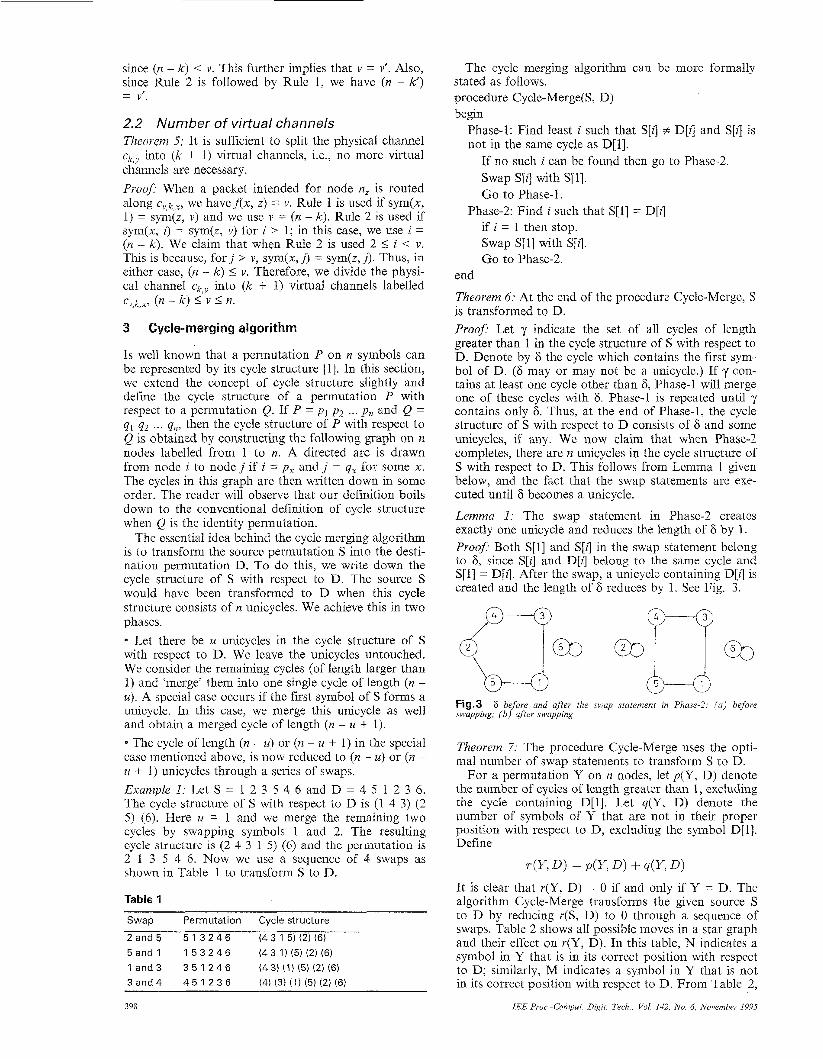
The essential idea behind the cycle merging algorithm is to transform the source permutation S into the desti- nation permutation D, To do this, we write down the cycle structure of S with respect to D. The source S would have been transformed to D when this cycle structure consists of n unicycles. We achieve this in two phases. e Let there be U unicycles in the cycle structure of S with respect to D. We leave the unicycles untouched. We consider the remaining cycles (of length larger than 1) and 'merge' them into one single cycle of length (n - U ) . A special case occurs if the first symbol of S forms a unicycle. In this case, we merge this unicycle as well and obtain a merged cycle of length (n - U + 1). * The cycle of length (n - U ) or (n - U + 1) in the special case mentioned above, is now reduced to (a - U ) or (n - U + 1) unicycles through a series of swaps. Example I : Let S = 1 2 3 5 4 6 and D = 4 5 1 2 3 6. The cycle structure of S with respect to D is (1 4 3) (2 5 ) (6). Here U = 1 and we merge the remaining two cycles by swapping symbols 1 and 2. The resulting cycle structure is (2 4 3 1 5 ) (6) and the permutation is 2 1 3 5 4 6. Now we use a sequence of 4 swaps as shown in Table 1 to transform S to D.
Table 1
Swap Permutation Cycle structure
2and5 5 1 3 2 4 6 (43 15) (2) (6) 5 a n d 1 1 5 3 2 4 6 (431 ) (5 ) (2 ) (6 ) 1 and 3 3 and 4
3 5 1 2 4 6 4 5 1 2 3 6
(4 3) (1) (5) (2) (6) (4) (3) (1) (5) (2) (6)
398
The cycle merging algorithm can be more formally stated as follows. procedure Cycle-Merge(& D) begin
Phase-1: Find least i such that S[i] + D[z] and S[i] is not in the same cycle as D[1].
If no such i can be found then go to Phase-2. Swap S[i] with S[1]. Go to Phase-1.
if i = 1 then stop. Swap SEX] with S[i]. Go to Phase-2.
Phase-2: Find i such that S[1] = D[z]
end
Theorem 6: At the end of the procedure Cycle-Merge, S is transformed to D. Proof Let y indicate the set of all cycles of length greater than 1 in the cycle structure of S with respect to D. Denote by 6 the cycle which contains the first sym- bol of D. (6 may or may not be a unicycle.) If y con- tains at least one cycle other than 6, Phase-1 will merge one of these cycles with 8. Phase-1 is repeated until y contains only 6. Thus, at the end of Phase-1, the cycle structure of S with respect to D consists of 6 and some unicycles, if any. We now claim that when Phase-2 completes, there are n unicycles in the cycle structure of S with respect to D. This follows from Lemma 1 given below, and the fact that the swap statements are exe- cuted until 6 becomes a unicycle.
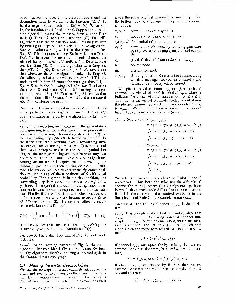
Lemma 1: The swap statement in Phase-2 creates exactly one unicycle and reduces the length of 6 by 1. Prooj? Both S[1] and S[i] in the swap statement belong to 6, since S[i] and D[zl belong to the same cycle and S[1] = D[i]. After the swap, a unicycle containing D[iJ is created and the length of 6 reduces by 1. See Fig. 3.
Fig.3 swapping; (b ) after swapping
6 before and after the swap statement in Phase-2: ( a ) before
Theorern 7. The procedure Cycle-Merge uses the opti- mal number of swap statements to transform S to D.
For a permutation Y on n nodes, let p ( Y , D) denote the number of cycles of length greater than 1, excluding the cycle containing D[l]. Let q ( Y , 0 ) denote the number of symbols of Y that are not in their proper position with respect to D, excluding the symbol D[l]. Define
T(Y, D ) = P ( Y , D ) + dY, D )
It is clear that r(Y, D) = 0 if and only if Y = D. The algorithm Cycle-Merge transforms the given source S to D by reducing r (S , D) to 0 through a sequence of swaps. Table 2 shows all possible moves in a star graph and their effect on r ( Y , D). In this table, N indicates a symbol in Y that is in its correct position with respect to D; similarly, M indicates a symbol in Y that is not in its correct position with respect to D. From Table 2,
IEE Proc -Cornput Digit Tech Vol 142, No 6, November 199s
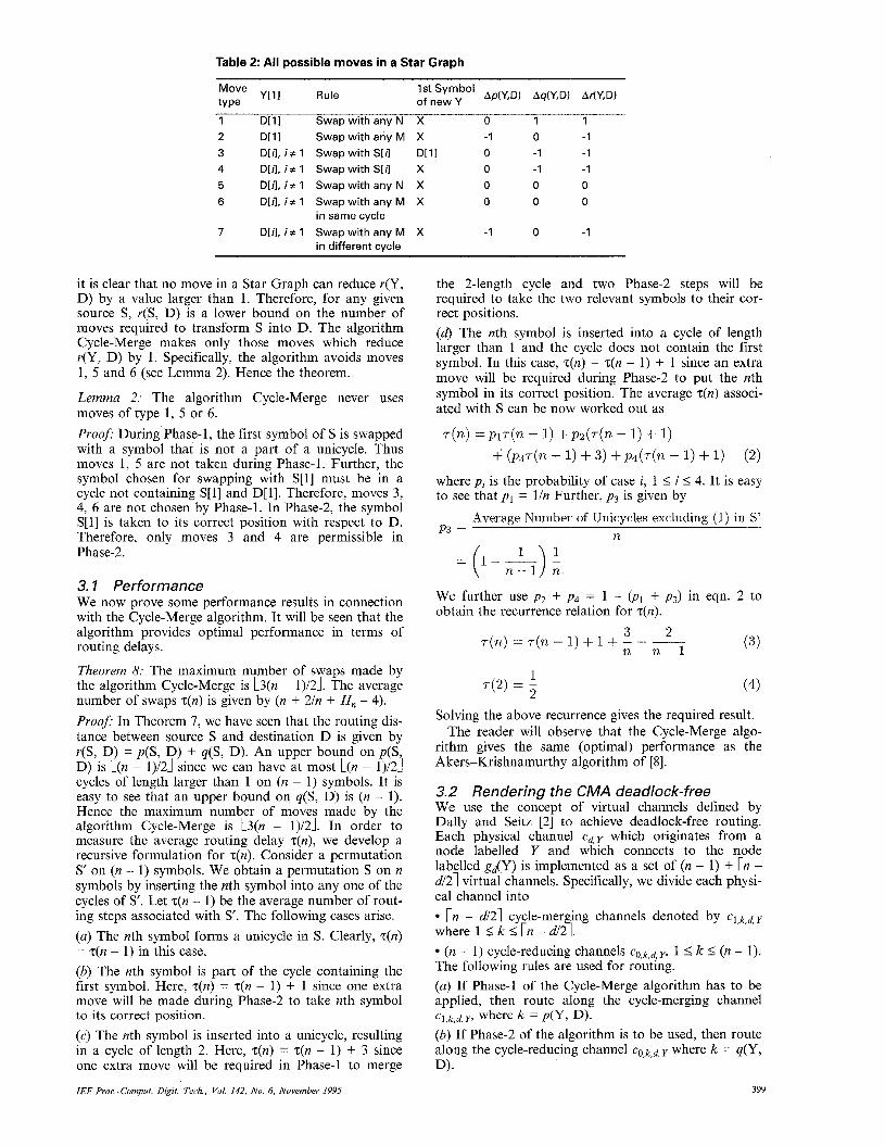
Table 2: All possible moves in a Star Graph
Ap(Y,D) Aq(Y,D) Ar(Y,D) 1 st Sym bo1 of new Y Y[11 Rule
Move type
1 D[11 Swap with any N X 0 1 1 2 D[11 Swap with any M X -1 0 -1 3 D[/], i + 1 Swap with S[/1 D[11 0 -1 -1 4 D[I], i + 1 Swap with S[d X 0 -1 -1 5 D[ij, i + 1 Swap with any N X 0 0 0 6 D[n, i + 1 Swap with any M X 0 0 0
7 DM, i z 1 Swap with any M X -1 0 -1 in same cycle
in different cvcle
it is clear that no move in a Star Graph can reduce r(Y, D) by a value larger than 1. Therefore, for any given source S, r (S , D) is a lower bound on the number of moves required to transform S into D. The algorithm Cycle-Merge makes only those moves which reduce r(Y, D) by 1. Specifically, the algorithm avoids moves 1, 5 and 6 (see Lemma 2). Hence the theorem.
Lemma 2: The algorithm Cycle-Merge never uses moves of type 1, 5 or 6. Proof: During Phase-1, the first symbol of S is swapped with a symbol that is not a part of a unicycle. Thus moves 1, 5 are not taken during Phase-1. Further, the symbol chosen for swapping with S[1] must be in a cycle not containing S[1] and D[1]. Therefore, moves 3, 4, 6 are not chosen by Phase-1. In Phase-2, the symbol S[1] is taken to its correct position with respect to D. Therefore, only moves 3 and 4 are permissible in Phase-2.
3. I Performance We now prove some performance results in connection with the Cycle-Merge algorithm. It will be seen that the algorithm provides optimal performance in terms of routing delays.
Theorem 8: The maximum number of swaps made by the algorithm Cycle-Merge is L3(n - 1)/2J. The average number of swaps z(n) is given by (n + 2/n + H,, - 4). Proofi In Theorem 7, we have seen that the routing dis- tance between source S and destination D is given by r(S, D) = p(S, D) + q ( S , D). An upper bound on p(S, D) is L(n - 1)/21 since we can have at most L(n - 11/21 cycles of length larger than 1 on (n - 1) symbols. It is easy to see that an upper bound oq q ( S , D) is (n - 1). Hence the maximum number of moves made by the algorithm Cycle-Merge is L3(n - 1)/21. In order to measure the average routing delay ~ ( n ) , we develop a recursive formulation for ~ ( n ) . Consider a permutation S’ on (n - 1) symbols. We obtain a permutation S on n symbols by inserting the nth symbol into any one of the cycles of S’. Let z(n - 1) be the average number of rout- ing steps associated with s’. The following cases arise. (a) The nth symbol forms a unicycle in S. Clearly, z(n) = z(n - 1) in this case. (b) The nth symbol is part of the cycle containing the first symbol. Here, ~ ( n ) = ~ ( n - 1) + 1 since one extra move will be made during Phase-2 to take nth symbol to its correct position. (c) The nth symbol is inserted into a unicycle, resulting in a cycle of length 2. Here, z(n) = z(n - 1) + 3 since one extra move will be required in Phase-1 to merge
IEE Pvoc -Cornput Digit Tech., Val 142, No 6, November 1995
the 2-length cycle and two Phase-2 steps will be required to take the two relevant symbols to their cor- rect positions. (d) The nth symbol is inserted into a cycle of length larger than 1 and the cycle does not contain the first symbol. In this case, zi(n) = z(n - 1) + 1 since an extra move will be required during Phase-2 to put the nth symbol in its correct position. The average z(n) associ- ated with S can be novv worked out as
r(n) = p 1 r ( n - 1) + p2(r(n - 1) + 1) + (p37(n - 1) + 3 ) + p4(r(n - 1) + 1) (2)
where pi is the probability of case i, 1 I i I 4. It is easy to see that p1 = l/n Further, p 3 is given by
Average Number of Unicycles excluding (1) in S’ n P3 =
= ( 1 - 5 ) - 1 n
We further use p2 + p4 = 1 - (PI + p 3 ) in eqn. 2 to obtain the recurrence relation for z(n).
( 3 )
(4) 1 2
r(2) = -
Solving the above recurrence gives the required result. The reader will observe that the Cycle-Merge algo-
rithm gives the same (optimal) performance as the Akers-Krishnamurthy algorithm of [8].
3.2 Rendering the CMA deadlock-free We use the concept of virtual channels defined by Dally and Seitz [2] to achieve deadlock-free routing. Each physical channel Cd,Y which originates from a node labelled Y and which connects to the node labelled g,(Y) is implemented as a set of (n - 1) + rn - d/21 virtual channels. Specifically, we divide each physi- cal channel into
rn - d/21 cycle-merging channels denoted by Cl,k,d,Y where 1 I k I rn - d/2 I. (n - 1) cycle-reducing channels c ~ , ~ , ~ , ~ , 1 S k 5 (n - 1).
The following rules are used for routing. (a) If Phase-1 of the Cycle-Merge algorithm has to be applied, then route aliong the cycle-merging channel
(b) If Phase-2 of the algorithm is to be used, then route along the cycle-reducing channel c ~ , ~ , ~ , where k = q(Y, D).
cl,k,d, Y, where k = Pe, D>.
399
Formally, the routing function RCMA for the cycle- merging algorithm may be defined as shown below.
R c M A ( c ~ , ~ , ~ , Y , D ) = Ci,k,d/,gd(Y) if /c =dgd(Y) ,D) > 0
are in same cycle in g d ( Y ) w.r . t . D
3.3 Number of virtual channels We now show that the number of virtual channels used in our algorithm of the previous section is sufficient. When the first routing rule is used and routing is done over a cycle-merging channel c ~ , ~ , ~ , ~ , k = p ( Y , D). An upper bound on p(Y, D) is rn - di21 since the Cycle- Merge algorithm chooses the leftmost symbol d in Y which is in one of the k cycles. There are at most (n ~
d) + 1 candidate symbols for selection. Since each of the k cycles requires at least two of these candidates, there can be at most rn - di21 cycles of interest. Hence k = p ( Y , d) I rn - di21.
Similarly, when we apply the second rule and route along a cycle-reducing channel C ~ , L , ~ , ~ , .! = q(Y, D) and an obvious upper bound for q(Y , D) is (n ~ 1).
3.4 Dead-lock free property Theorem 9: The routing function RCMA is deadlock- free. Pro05 The following three cases occur while routing using our algorithm. Case 1. A packet received along a cycle-merging chan- nel is forwarded along a cycle-merging channel Case 2. A packet received along a cycle-merging chan- nel is forwarded along a cycle-reducing channel Case 3. A packet received along a cycle-reducing chan- nel is forwarded along a cycle-reducing channel In Case 2, the channel subscripts are obviously decreas- ing, since a cycle-merging channel has a 1 in the first position and a cycle-reducing channel has a 0 in the first position. In Case 1, if the incoming channel is
and the outgoing channel is cl,w’,d,gd,(Y) then we claim that w’ = w - 1 < w. Recall that w = p ( Y , D)
and w’ = p(g,(Y), D). Since Phase-1 is in progress, each step of Phase-1 reduces the size of y by 1. (See Theorem 6) .
In Case 3, if the incoming channel is denoted cO,w,d,y and the outgoing channel is denoted co,w’,d‘,gd,(Y), then we claim that w’ = w - 1. Once again, recall that w = q(Y, D) and w’ = 4(g,(Y), D). Phase-2 is being used, and as illustrated in Theorem 6, the function 4 decreases by 1 after each step of Phase-2.
4 Conclusions
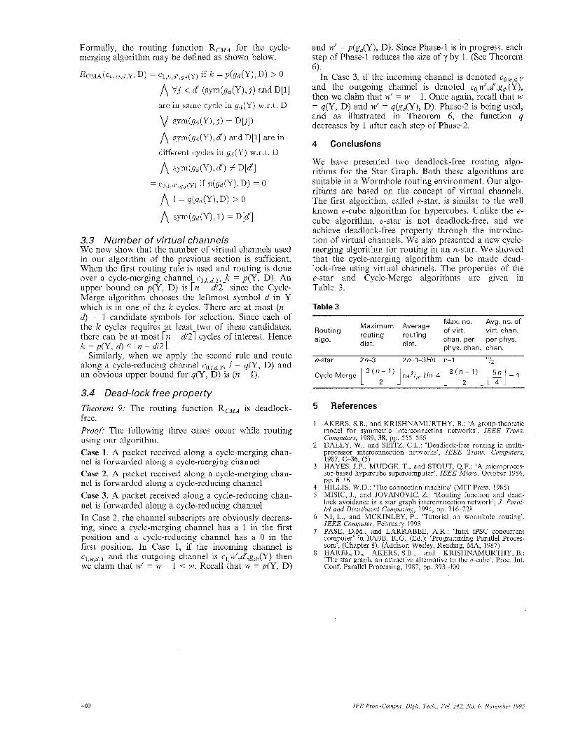
We have presented two deadlock-free routing algo- rithms for the Star Graph. Both these algorithms are suitable in a Wormhole routing environment. Our algo- rithms are based on the concept of virtual channels. The first algorithm, called e-star, is similar to the well known e-cube algorithm for hypercubes. Unlike the e- cube algorithm, e-star is not deadlock-free, and we achieve deadlock-free property through the introduc- tion of virtual channels. We also presented a new cycle- merging algorithm for routing in an n-star. We showed that the cycle-merging algorithm can be made dead- lock-free using virtual channels. The properties of the e-star and Cycle-Merge algorithms are given in Table 3.
Table 3
Max. no. Avg. no. of Maximum Average routing routing dist. dist.
Routing of virt. virt. chan. algo. chan. per per phys.
phys. chan. chan.
e-star 2n-3 2n+l-3Hn n-I “12
Cycle-Merge L3( ]n+2/ ,+Hn-4 L-1 - 1
5 References
1 AKERS, S.B., and KRISHNAMURTHY, B.: ‘A group-theoretic model for svmmetric interconnection networks’. ZEEE Trans. Computers, l h 9 , 38, pp. 555-566 DALLY, W., and SEITZ, C.L.: ‘Deadlock-free routing in multi- 2 processor interconnection networks’, IEEE Trans. computers, 1987, C-36, (5) HAYES, J.P., MUDGE, T., and STOUT, Q.F.: ‘A microproces- sor-based hypercube supercomputer’, IEEE Micuo, October 1986, pp. 6 1 6
4 HILLIS, W.D.: ‘The connection machine’ (MIT Press, 1985) 5 MISIC, J., and JOVANOVIC, Z.: ‘Routing function and dead-
lock avoidance in a star graph interconnection network’, J. Paral- lel and Distributed Computing, 1994, pp. 216-228
6 NI, L., and MCKINLEY, P.: ‘Tutorial on wormhole routing’, IEEE Computer, February 1993
7 PASE, D.M., and LARRABEE, A.R.: ‘Intel iPSC concurrent computer’ in BABB, R.G. (Ed.): ‘Programming Parallel Proces- sors’, (Chapter 8), (Addison Wesley, Reading, MA, 1987)
8 HAREL, D., AKERS, S.B., and KRISHNAMURTHY, B.: ‘The star graph: an attractive alternative to the n-cube’, Proc. Int. Conf. Parallel Processing, 1987, pp. 393400
3
400 IEE Pvoc.-Comput. Digit. Tech., Vol. 142, No. 6, November I995