Embed Size (px)
Citation preview

Dear Author, Please, note that changes made to the HTML content will be added to the article before publication, but are not reflected in this PDF. Note also that this file should not be used for submitting corrections.
Nonsingular crack modelling in orthotropic plates by four equivalentsingle layersQ6
Q5 Andr�as Szekr�enyesBudapest University of Technology and Economics Department of Applied Mechanics, Müegyetem rkp. 5, 1111 Budapest, Building MM, HungaryQ2
a r t i c l e i n f o
Article history:Received 4 March 2015Accepted 8 August 2015Available online xxx
Keywords:DelaminationMixed mode II/III fractureEnergy release rateSecond-order plate theoryTheoreom of autocontinuityQ3
a b s t r a c t
In this work the second- and third-order laminated plate theories are applied to model delaminatedcomposite plates with material orthotropy. The method of four equivalent single layers is proposed and ageneral third-order displacement field is utilized in each layer. The kinematic continuity between thelayers is established by the system of exact kinematic conditions. Apart from the continuity of the in-plane displacements between the interfaces of the layers even the continuity of shear strains, theirderivatives and curvatures is imposed. As a novelty a so-called shear strain control condition is intro-duced, which means that the shear strains at two or more points located along the thickness are imposedto be the same. Using the proposed conditions the equilibrium equations are derived for the delaminatedand undelaminated regions of the plate. Plates with different boundary conditions are solved as ex-amples and the theorem of autocontinuity is introduced, which is essentially related to the continuityconditions between the delaminated and undelaminated parts. The stress and displacement fields aswell as the J-integral are determined in the examples and compared to finite element calculations. Theresults indicate that the control condition works very well in the case of the second-order plate theory, incontrast it is rather a disadvantage in the case of the third-order approximation.
© 2015 Published by Elsevier Masson SAS.
1. Introduction
Anisotropic composites (Chaudhuri and Balaraman, 2007;Czig�any and De�ak, 2012; M�esz�aros et al., 2013) are often utilizedin air-, spacecraft (Smojver and Ivan�cevi�c, 2010; Ivan�cevi�c andSmojver, 2011; Smojver and Ivan�cevi�c, 2011, 2012; Langdon et al.,2014) and sport industry (Jiang, 2014; Li and Jing, 2014; Su, 2014;Zhang, 2014; Tang, 2014), composite panels are also applied incars and vehicles (Norhidayah et al., 2014; Wennberg and Stichel,2014; Khan et al., 2014), ships (Chirica et al., 2011; Chirica, 2013),pressure vessels (Gheshlaghi et al., 2006) and many other engi-neering applications (Goch et al., 2012). Themechanical behavior oflaminated composite plates and shells can be described by differenttheories. The classical laminated plate theory (CLPT) is based on theKirchhoff assumption and so, it does not take the shear deformationinto account (Radosavljevi�c and Dra�zi�c, 2010; Eftekhari and Jafari,2012; Hajheidari and Mirdamadi, 2013). The first-order sheardeformation (FSDT or Mindlin) theory assumes constant shearstrain distribution over the thickness of the plate (Kreja and
Schmidt, 2006; Endo and Kimura, 2007; Assie et al., 2012; Batista,2012; Nanda and Sahu, 2012; Sabik and Kreja, 2013; Endo, 2015).As a next step, the second-order plate theory (SSDT) proposes thatthe in-plane displacements are captured by quadratic functions interms of the through-thickness coordinate (Baddour, 2011; Izadiand Tahani, 2010; Shahrjerdi et al., 2011, 2010). The third-ordershear deformation plate theory (TSDT) (Talha and Singh, 2010;Aragh et al., 2013) as well as the refined Reddy third-order theory(Thai et al., 2012; Oktem et al., 2013; Taj et al., 2013; Batista, 2012;Bodaghi and Saidi, 2010; Thai et al., 2012) are also very common todescribe the mechanical behavior of anisotropic plates and shells.
The 3D and elasticity based solutions (Alibeigloo and Zanoosi,2013; Chang and Tarn, 2012; Yang et al., 2012) are also availablein the literature, as well as the different layerwise approximations(Arya et al., 2002; Ferreira et al., 2011; Ovesy et al., 2015; Saeediet al., 2012a,b, 2013a,b; Lerpiniere et al., 2014; Sahoo and Singh,2014b). Other higher-order theories (Steigmann, 2012; Xianget al., 2012; Shi, 2007; Zhao et al., 2013; Lu et al., 2013; Shimpiand Patel, 2006) and those based on trigonometric or otherappropriate functions (Thai and Vo, 2013; Thai and Choi, 2013;Sahoo and Singh, 2014a, 2013a,b) are useful in the case of func-tionally graded (FGM) plates.E-mail address: [email protected].
URL: http://www.mm.bme.hu/~szeki
Contents lists available at ScienceDirect
European Journal of Mechanics A/Solids
journal homepage: www.elsevier .com/locate/ejmsol
http://dx.doi.org/10.1016/j.euromechsol.2015.08.0050997-7538/© 2015 Published by Elsevier Masson SAS.
European Journal of Mechanics A/Solids xxx (2015) 1e27
123456789101112131415161718192021222324252627282930313233343536373839404142434445464748495051525354
555657585960616263646566676869707172737475767778798081828384858687888990919293949596979899
100101102103104105106107108109110111112113114115116117118119
EJMSOL3223_proof ■ 8 September 2015 ■ 1/27
Please cite this article in press as: Szekr�enyes, A., Nonsingular crack modelling in orthotropic plates by four equivalent single layers, EuropeanJournal of Mechanics A/Solids (2015), http://dx.doi.org/10.1016/j.euromechsol.2015.08.005

It is clear that many plate and shell theories are proposed in theliterature, however, the application of these theories to model de-laminations is started only few years ago. The delamination is atypical and common damage mode in composite laminates. Thepresence of delaminations (Rizov, 2012a,b; Ahn et al., 2012) andcracks (Hajikazemi and Sadr, 2014b,a) in the material reduces thestiffness, strength and lifetime, it also changes the dynamic prop-erties and the behavior of the structure against the loss of stability.Therefore it is essential to develop new models for the delamina-tion analysis of composite materials. In this respect the work byDavidson et al. (2000) is noteworthy. It has also to be mentionedthat coupled multilayer/interface models have already been intro-duced in the literature, which are able to provide accurate energyrelease rate (ERR) calculations compared to FE models using solidtype elements (Bruno and Greco, 2001; Bruno et al., 2003, 2005).An important aspect of these formulations is that it avoids thecomplications arising from the oscillatory singularities for adelamination between different materials.
The delaminations may take place because of low-velocityimpact (Ganapathy and Rao, 1998; Rizov et al., 2005; Christoforouet al., 2008; Burlayenko and Sadowski, 2012; Zammit et al., 2011;Wang et al., 2012; Goodmiller and TerMaath, 2014),manufacturing defects (Zhang and Fox, 2007; Zhou et al., 2013) andfree edge effects (Sarvestani and Sarvestani, 2012; Ahn et al., 2013).The resistance against the delamination is characterized by mode-I(Jumel et al., 2011a,b; Salem et al., 2013; Kim et al., 2011; Peng et al.,2011; Gracia et al., 2015) mode-II (Arrese et al., 2010; Argüelleset al., 2011; Petrova et al., 2012; Petrova and Sadowski, 2012;Yoshihara and Satoh, 2009; Rizov and Mladensky, 2012) mode-III(Rizov et al., 2006; Szekr�enyes, 2009a, 2011a,b; Johnston et al.,2014; Johnston and Davidson, 2014; Rodríguez-Gonz�alez et al.,2014; Khoshravan and Moslemi, 2014; L�opez-Men�endez et al.,2014; Marat-Mendes and Freitas, 2009; Mehrabadi and Khosra-van, 2013; Yoshihara, 2006) mixed-mode I/II (de Baere et al., 2012;Davidson et al., 2009; Fern�andez et al., 2013; Islam and Kapania,2014; Peng et al., 2012; Kenane et al., 2010; Marat-Mendes andFreitas, 2010; Nikbakht et al., 2010; Nikbakht and Choupani, 2008;Plain and Tong, 2011; Liu et al., 2015; Pereira et al., 2014) mixed-mode II/III (Szekr�enyes, 2007; Kondo et al., 2011, 2010;Mladensky and Rizov, 2013; Kotousov et al., 2013, 2012;Szekr�enyes, 2012; Mehrabadi, 2013, 2014; Miura et al., 2012;Takeda et al., 2013; Suemasu et al., 2010) mixed-mode I/III (Miuraet al., 2014; Szekr�enyes, 2009b) and mixed-mode I/II/III (Davidsonand Sediles, 2011; Szekr�enyes, 2011a,b) fracture test.
The previous developments e that this paper is based on e aresummarized as follows: In some recent papers the so-calledinterface constraints were applied to model delaminated compos-ite plates by CLPT, FSDT, SSDT and TSDT with midplane cracks andsymmetric lay-up (Szekr�enyes, 2014a,c,e, 2013a). Later, the modelswere generalized to asymmetrically delaminated plates and the so-called system of exact kinematic conditions (SEKC) was proposedfor the FSDT (Szekr�enyes, 2013b), SSDT (Szekr�enyes, 2014b) andReddy third-order theory (Szekr�enyes, 2014d). In these papers themethod of two equivalent single layers (2ESLs) was applied, i.e. thewhole plate was divided into two parts in the plane of the delam-ination: a top and a bottom plate was analyzed. Simply supportedplates were investigated with straight widthwise delamination.Among the mentioned models Reddy third-order theory was foundto be the most promising, however, it will be shown in this paperthat a better performance can be achieved by the present method.
The novelty of this paper is the proposed method of fourequivalent single layers (4ESLs). The top and bottom plates arecaptured by two ESLs including the proper kinematic continuity.Furthermore, the updated form of the SEKC is presented includingthe conditions of continuous shear strain, its derivative and
curvature at the interface planes and a so-called shear strain con-trol condition. From the point of view of the continuity conditionsbetween the delaminated and undelaminated regions the theoremof autocontinuity is formulated. The novel technique is applied todelaminated L�evy plates with different geometry and boundaryconditions.
2. Semi-layerwise laminated plate theory e the method offour ESLs
Fig. 1 shows the section of the layered plate element in the X�Zplane, while in Fig. 2 the Y�Z plane is shown. The elements containan interfacial delamination parallel to the Y axis, i.e. it goes acrossthe entire platewidth. The delamination divides the plate into a topand a bottom subplate. Each subplate is modelled by further twoESLs. The interface planes between the ESLs are called the pertur-bation planes. In accordance with the literature review, it is clearthat the ESLs can be captured by different plate theories. In thisworkwe apply the SSDTand TSDT theories. The general third-orderTaylor series expansion of the displacement functions results in thefollowing displacement field (Talha and Singh, 2010; Panda andSingh, 2011; Singh and Panda, 2014; Panda and Singh, 2009):
ui�x;y;zðiÞ
�¼ u0ðx;yÞþu0iðx;yÞþ qðxÞiðx;yÞzðiÞ þfðxÞiðx;yÞ
�zðiÞ�2
þlðxÞiðx;yÞ�zðiÞ�3
vi
�x;y;zðiÞ
�¼ v0ðx;yÞþ v0iðx;yÞþ qðyÞiðx;yÞzðiÞ þfðyÞiðx;yÞ
�zðiÞ�2
þlðyÞiðx;yÞ�zðiÞ�3
wiðx;yÞ ¼wiðx;yÞ(1)
where i is the index of the actual ESL, z(i) is the local throughthickness coordinate of the ith ESL (refer to Fig. 1), u0 and v0 are theglobal, u0i and v0i are the local membrane displacements, moreover,q means the rotations of the cross sections about the X and Y axes(refer to Fig. 1), f denotes the second-order, l represents the third-order terms in the displacement functions. The displacementfunctions of SSDTcan be obtained by reducing Eq. (1) and taking l(x)i ¼ l(y)i ¼ 0 (Izadi and Tahani, 2010; Baddour, 2011; Petrolito, 2014).
3. The system of exact kinematic conditions e SEKC
The system of exact kinematic conditions has been developed in(Szekr�enyes, 2013b) for first-order Mindlin plates and it was sub-sequently extended to second- (Szekr�enyes, 2014b) and third-orderplates (Szekr�enyes, 2014d). In the mentioned papers the plate wasdivided into two ESLs in the undelaminated portion. Among theseproposed solutions, Reddy's theory provided the best agreementwith the finite element (FE) results (based on the virtual crackclosure technique (VCCT, (Bonhomme et al., 2010; Valvo, 2012)) forasymmetrically delaminated composite plates. In spite of that, ifthe delamination is very close to the free surface of the plate, theneven Reddy's theory leads to inaccurate results. The aim of thispaper is to model the delaminated plate by 4ESLs and to introducethe necessary conditions to obtain the best possible solutions underassumed plane stress state.
We assume that a plate consisting of orthotropic plies contains asingle through-width delamination. The delamination front isparallel to the Y axis. A displacement field given by Eq. (1) isassociated to each ESLs. The kinematic continuity between theadjacent ESLs is established by the SEKC requirements. The first setof conditions formulates the continuity of the in-plane displace-ments between the neighboring plies as:
A. Szekr�enyes / European Journal of Mechanics A/Solids xxx (2015) 1e272
1234567891011121314151617181920212223242526272829303132333435363738394041424344454647484950515253545556575859606162636465
66676869707172737475767778798081828384858687888990919293949596979899
100101102103104105106107108109110111112113114115116117118119120121122123124125126127128129130
EJMSOL3223_proof ■ 8 September 2015 ■ 2/27
Please cite this article in press as: Szekr�enyes, A., Nonsingular crack modelling in orthotropic plates by four equivalent single layers, EuropeanJournal of Mechanics A/Solids (2015), http://dx.doi.org/10.1016/j.euromechsol.2015.08.005

�uðiÞ; vðiÞ;wðiÞ
����zðiÞ¼ti=2
¼�uðiþ1Þ; vðiþ1Þ;wðiþ1Þ
����zðiþ1Þ¼�tiþ1=2
(2)
where t is the thickness of the specified layer. The second set ofconditions defines the global membrane displacements (u0, v0) atthe reference plane of the actual region. If the location of thereference plane is zðkÞR and is located in the kth layer, then therelevant conditions become:
uðkÞ���zðkÞ¼zðkÞR
� u0 ¼ 0; vðkÞ���zðkÞ¼zðkÞR
� v0 ¼ 0 (3)
The two sets of conditions given by Eqs. (2)e(3) are sufficient todevelop semi-layerwise models using the FSDT. If the SSDT or TSDTis applied, then we can impose the shear strain continuity at the
interface planes. In accordance with Figs. 1b and 2b these condi-tions are formulated as:�gxzðiÞ;gyzðiÞ
����zðiÞ¼ti=2
¼�gxzðiþ1Þ;gyzðiþ1Þ
����zðiþ1Þ¼�tiþ1=2
(4)
For the TSDT theory two more sets of conditions are reasonableto introduce. The imposition of continuous shear strain derivativesand curvatures prevent the unwanted oscillations in the stressdistributions (see Figs. 1b and 2b):
�vgxzðiÞvzðiÞ
;vgyzðiÞvzðiÞ
����zðiÞ¼ti=2
¼�vgxzðiþ1Þvzðiþ1Þ ;
vgyzðiþ1Þvzðiþ1Þ
����zðiþ1Þ¼�tiþ1=2
(5)
Fig. 1. Cross sections and deformation of the top and bottom plate elements of a delaminated plate in the XeZ plane (a). Distribution of the transverse shear strains by SSDT andTSDT (b).
Fig. 2. Cross sections and deformation of the top and bottom plate elements of a delaminated plate in the YeZ plane (a). Distribution of the transverse shear strains by SSDT andTSDT (b).
A. Szekr�enyes / European Journal of Mechanics A/Solids xxx (2015) 1e27 3
1234567891011121314151617181920212223242526272829303132333435363738394041424344454647484950515253545556575859606162636465
66676869707172737475767778798081828384858687888990919293949596979899
100101102103104105106107108109110111112113114115116117118119120121122123124125126127128129130
EJMSOL3223_proof ■ 8 September 2015 ■ 3/27
Please cite this article in press as: Szekr�enyes, A., Nonsingular crack modelling in orthotropic plates by four equivalent single layers, EuropeanJournal of Mechanics A/Solids (2015), http://dx.doi.org/10.1016/j.euromechsol.2015.08.005

and: v2gxzðiÞv�zðiÞ�2; v2gyzðiÞ
v�zðiÞ�2!���
zðiÞ¼ti=2¼ v2gxzðiþ1Þv�zðiþ1Þ�2; v
2gyzðiþ1Þv�zðiþ1Þ�2
!���zðiþ1Þ¼�tiþ1=2
(6)An important addition compared to previous papers is the so-
called shear strain control condition (SSCC). In accordance withReddy theory the top and bottom surfaces of the plate are traction-free (zero shear stresses). If two ESLs are applied this conditioninvolves a little over-stiffening of the system. Moreover, if thesystem is modelled by 4ESLs the traction-free conditions leads tooverconstraining the model and wrong results are obtained.Therefore, instead of imposing zero stresses at the free surfaces weimpose the identical shear strain values at the boundary planes.Figs. 1a and 2a show the so-called control line and the controlledshear strain distributions. The set of conditions applied is:�gxzðlÞ;gyzðlÞ
����zðlÞ¼�tl=2
¼�gxzðmÞ;gyzðmÞ
����zðmÞ¼�tm=2
(7)
where l and m denote the boundaries, where the shear strains areequal to each other. The SEKC can be applied for the undelaminatedand delaminated portions of the plate. Moreover these conditionscan be implemented into any plate theory.
4. Development of kinematically admissible displacementfields
The SEKC is applied to the problem shown in Figs. 1 and 2. Usingthe conditions defined by Eqs. (2)e(7) we can eliminate certainparameters from Eq. (1), which involves 34 parameters altogetherplus the deflections (wi(x,y)). This step is called parameter elimi-nation. The parameters to be eliminated are chosen in order toobtain a system of equations, which contain linearly independentequations. However, the global membrane parameters should beremaining or primary parameters, the local membrane displace-ments are typically secondary parameters, that should be eliminatedfrom the displacement field. In the subsequent sections the unde-laminated and delaminated regions are discussed separately. In thefirst step, the TSDT solution is presented, then in the second stepthe SSDT field equations are obtained by the reduction of the TSDTequations.
4.1. Undelaminated plate region
The transition zone around the delamination front in the X�Zplane of the composite plate is shown in Fig. 1a. The distribution ofthe in-plane displacement functions is quadratic in the case of theSSDT and cubic for the TSDT. The corresponding shear strain dis-tributions are shown in Fig. 1b: it is piecewise linear by SSDT andpiecewise quadratic by TSDT with continuous derivatives and cur-vatures in the latter case. In accordance with Figs. 1a and 2a, thefollowing conditions are formulated between the four ESLs (con-tinuity of in-plane displacement at the interface planes):
ðu1; v1;w1Þ���zð1Þ¼t1=2
¼ ðu2; v2;w2Þ���zð2Þ¼�t2=2
ðu2; v2;w2Þ���zð2Þ¼t2=2
¼ ðu3; v3;w3Þ���zð3Þ¼�t3=2
ðu3; v3;w3Þ���zð3Þ¼t3=2
¼ ðu4; v4;w4Þ���zð4Þ¼�t4=2
(8)
The reference plane belongs to the second ESL, therefore, thefollowing condition is imposed:
ðu2; v2Þ���zð2Þ¼zð2ÞR
¼ ðu0ðx; yÞ; v0ðx; yÞÞ (9)
where the zð2ÞR ¼ 1=2ðt3 þ t4 � t1Þ in accordance with Fig. 1a andactually coincides with the global midplane of the model (Reddy,2004). The next set of conditions imposes the continuous shearstrains at the interface planes:
�gxzð1Þ;gyzð1Þ
����zð1Þ¼t1=2
¼�gxzð2Þ;gyzð2Þ
����zð2Þ¼�t2=2�
gxzð2Þ;gyzð2Þ����
zð2Þ¼t2=2¼�gxzð3Þ;gyzð3Þ
����zð3Þ¼�t3=2�
gxzð3Þ;gyzð3Þ����
zð3Þ¼t3=2¼�gxzð4Þ;gyzð4Þ
����zð4Þ¼�t4=2
(10)
As discussed previously, the oscillations in the shear straindistribution can be reduced by ensuring continuous shear strainderivatives at the interface planes 1e2 and 3e4:
�vgxzð1Þvzð1Þ
;vgyzð1Þvzð1Þ
�����zð1Þ¼t1=2
¼�vgxzð2Þvzð2Þ
;vgyzð2Þvzð2Þ
�����zð2Þ¼�t2=2�
vgxzð3Þvzð3Þ
;vgyzð3Þvzð3Þ
�����zð3Þ¼t2=2
¼�vgxzð4Þvzð4Þ
;vgyzð4Þvzð4Þ
�����zð4Þ¼�t4=2
(11)
furthermore, by imposing continuous shear strain curvatures in thesame planes by using the conditions below:
v2gxzð1Þ
v�zð1Þ�2; v2gyzð1Þ
v�zð1Þ�2!�����
zð1Þ¼t1=2
¼ v2gxzð2Þ
v�zð2Þ�2; v2gyzð2Þ
v�zð2Þ�2!�����
zð2Þ¼�t2=2 v2gxzð3Þ
v�zð3Þ�2; v2gyzð3Þ
v�zð3Þ�2!�����
zð3Þ¼t3=2
¼ v2gxzð4Þ
v�zð4Þ�2; v2gyzð4Þ
v�zð4Þ�2!�����
zð4Þ¼�t4=2
(12)
To further reduce the number of parameters in the displacementfield and to obtain more accurate results, the SSCC is applied at thetop and bottom boundaries:�gxzð1Þ;gyzð1Þ
����zð1Þ¼�t1=2
¼�gxzð4Þ;gyzð4Þ
����zð4Þ¼t4=2
(13)
In Eq. (1) the displacement functions are modified in order tosatisfy Eqs. (8)e(13). In the general sense, by applying the SSDT andTSDT theories the in-pane displacement functions can be writtenas:
ui ¼ u0 þ�Kð0Þij þKð1Þ
ij zðiÞ þ Kð2Þij
�zðiÞ�2 þKð3Þ
ij
�zðiÞ�3�
jðxÞj
vi ¼ v0 þ�Kð0Þij þKð1Þ
ij zðiÞ þKð2Þij
�zðiÞ�2 þKð3Þ
ij
�zðiÞ�3�
jðyÞj(14)
where the matrices denoted by Kij are related to the geometry (ESLthicknesses), i refers to the ESL number, j defines the component inj, which is the vector of primary parameters, finallywi(x,y)¼w(x,y)for each ESLs, i.e. the transverse normals of each ESL are inex-tensible (Reddy, 2004).
4.1.1. Third-order plate theoryUsing the conditions above (Eqs. (8)e(13)) we can eliminate
twentyfour parameters from Eq. (1), the secondary parameters are:u0i, v0i, q(x)i, q(y)i, f(x)i, f(y)i for i ¼ 1,3, l(x)i, l(y)i for i ¼ 1…4. Theprimary parameters are: u0, v0, q(x)i, q(y)i for i ¼ 2,4 and f(x)i, f(y)i for
i ¼ 2,4. The nonzero elements of the matrices Kð0Þij , Kð1Þ
ij , Kð2Þij and
Kð3Þij are defined in Appendix A. The vector of primary parameters
is: j(p) ¼ (q(p)2 f(p)2 q(p)4 f(p)4)<SUP>T</SUP> with p ¼ x or y.
A. Szekr�enyes / European Journal of Mechanics A/Solids xxx (2015) 1e274
1234567891011121314151617181920212223242526272829303132333435363738394041424344454647484950515253545556575859606162636465
66676869707172737475767778798081828384858687888990919293949596979899
100101102103104105106107108109110111112113114115116117118119120121122123124125126127128129130
EJMSOL3223_proof ■ 8 September 2015 ■ 4/27
Please cite this article in press as: Szekr�enyes, A., Nonsingular crack modelling in orthotropic plates by four equivalent single layers, EuropeanJournal of Mechanics A/Solids (2015), http://dx.doi.org/10.1016/j.euromechsol.2015.08.005

4.1.2. Second-order plate theoryIn this case l(x)i ¼ 0 and l(y)i ¼ 0 in Eq. (1). Eqs. (8)e(9) apply
together with Eq. (10) (shear strain continuity), however Eqs. (11)and (12) are omitted. Therefore we can eliminate sixteen parame-ters from Eq. (1), the secondary parameters are: u0i, v0i, q(x)i, q(y)i,f(x)i, f(y)i for i ¼ 1,3. The primary parameters are: u0, v0, q(x)i, q(y)i fori ¼ 2,4, f(x)i and f(y)i for i ¼ 2,4. The nonzero elements of the
matrices Kð0Þij , Kð1Þ
ij and Kð2Þij are defined in Appendix B. Obviously
Kð3Þij ¼ 0 in this case. The vector of primary parameters becomes:
j(p) ¼ (q(p)2 f(p)2 q(p)4 f(p)4)<SUP>T</SUP> with p ¼ x or y, i.e. thesame as that for the TSDT.
4.2. Delaminated plate portion
In the delaminated portion (refer to Figs. 1b and 2b) the top andbottom plates are modelled by two ESLs, and thus the first and thirdof Eq. (8) still hold. It is important to note that in accordance withEq. (8) the transverse deflections of the top and bottomplates of thedelaminated region are identical (constrained mode model,(Szekr�enyes, 2014d)). In other words, the crack opening is elimi-nated in the plate, and the problem provides essentially mixed-mode II/III fracture without the presence of mode-I. The aim is topredict the mechanical fields in the plate as accurately as possiblecompared to FE calculations. If this is done for mixed-mode II/III,then the model can be extended to general mixed-mode I/II/III casein the course of the further research work. The definition of the topand bottom reference planes involve:
ðu1; v1Þjzð1Þ¼t2=2 ¼ ðu0bðx; yÞ; v0bðx; yÞÞðu3; v3Þjzð3Þ¼t4=2 ¼ ðu0tðx; yÞ; v0tðx; yÞÞ (15)
where u0b and u0t are the global membrane displacements of thebottom and top layers in accordance with Figs. 1 and 2. Further-more, the first and third of Eq. (10) apply again, as well as Eqs. (11)and (12) leading to eleven conditions altogether. Three moreequations are formulated by using the shear strain controlconditions:�gxzð1Þ;gyzð1Þ
����zð1Þ¼�t1=2
¼�gxzð2Þ;gyzð2Þ
����zð2Þ¼t2=2�
gxzð3Þ;gyzð3Þ����
zð3Þ¼�t3=2¼�gxzð4Þ;gyzð4Þ
����zð4Þ¼t4=2�
gxzð1Þ;gyzð1Þ����
zð1Þ¼�t1=2¼�gxzð4Þ;gyzð4Þ
����zð4Þ¼t4=2
(16)
i.e., instead of imposing traction-free boundaries we control thestrain distribution by having equal values at the boundaries.
4.2.1. Third-order plate theoryThe first and third in Eq. (8) hold, moreover Eq. (14) is implied,
again the first and third of Eq. (10) are utilized together with Eqs.(11) and (12) and Eqs. (15) and (16) leading to 26 conditions alto-gether. The secondary parameters are: u0i, v0i, f(x)i, f(y)i for i¼ 1…3,l(x)i, l(y)i for i ¼ 1…4. The primary parameters are: u0t, v0t, u0b, v0b,q(x)i, q(y)i for i ¼ 2,4 and f(x)i, f(y)i for i ¼ 4. The modified displace-ment field has the same form as that given by Eq. (14), the co-efficients denoted by K are placed in Appendix A and: j(p) ¼ (q(p)2q(p)4 f(p)4)<SUP>T</SUP>, where p ¼ x or y.
4.2.2. Second-order plate theoryIn this case l(x)i ¼ 0 and l(y)i ¼ 0 in Eq. (1). The first and third in
Eq. (8) hold, moreover Eq. (14) is implied, again the first and third ofEq. (10) is utilized, however Eqs. (11) and (12) are omitted. Thestrain control conditions are applied through Eq. (16). Therefore wecan eliminate eighteen parameters from Eq. (14), the secondary
parameters are: u0i, v0i, f(x)i, f(y)i for i ¼ 1,3 and 4, and q(x)i, q(y)i fori¼ 1,3 respectively. The primary parameters are: u0t, v0t, u0b, v0b, q(x)i, q(y)i for i¼ 2,4, f(x)i and f(y)i for i¼ 2. The elements of the matrices
Kð0Þij , Kð1Þ
ij and Kð2Þij are defined in Appendix B. Apparently Kð3Þ
ij ¼ 0 in
this case. The vector of primary parameters takes the form:j(p) ¼ (q(p)2 f(p)2 q(p)4)<SUP>T</SUP>, where p ¼ x or y.
5. Equilibrium equations
The strain field in an elastic body in terms of the displacementfield is obtained by the following equation (Chou and Pagano,1967):
εij ¼12�ui;j þ uj;i
�(17)
where εij is the strain tensor, ui is the displacement vector field. Byassuming plane stress state in the plate the vector of in-planestrains becomes (Reddy, 2004):
8<:εxεygxy
9=;ðiÞ
¼
8><>:εð0Þx
εð0Þy
gð0Þxy
9>=>;ðiÞ
þ zðiÞ$
8><>:εð1Þx
εð1Þy
gð1Þxy
9>=>;ðiÞ
þhzðiÞi2$
8><>:εð2Þx
εð2Þy
gð2Þxy
9>=>;ðiÞ
þhzðiÞi3$
8><>:εð3Þx
εð3Þy
gð3Þxy
9>=>;ðiÞ
(18)
The vector of transverse shear strains is:
gxzgyz
ðiÞ
¼(gð0Þxz
gð0Þyz
)ðiÞ
þ zðiÞ$
(gð1Þxz
gð1Þyz
)ðiÞ
þhzðiÞi2$
(gð2Þxz
gð2Þyz
)ðiÞ
(19)
By using the constitutive equations (Koll�ar and Springer, 2003;Reddy, 2004) the stress resultants are calculated by integratingthe stresses over the thicknesses of each ESL:
8>>><>>>:Nab
Mab
LabPab
9>>>=>>>;ðiÞ
¼Zti=2
�ti=2
sab
8>>><>>>:1z
z2
z3
9>>>=>>>;ðiÞ
dzðiÞ;
8><>:Qa
RaSa
9>=>;ðiÞ
¼Zti=2
�ti=2
saz
8><>:1z
z2
9>=>;ðiÞ
dzðiÞ
(20)
where a and b takes x or y. The relationship between the strain fieldand the stress resultants is (Szekr�enyes, 2014d):
8>><>>:fNgfMgfLgfPg
9>>=>>;ðiÞ
¼
2664½A� ½B� ½D� ½E�½B� ½D� ½E� ½F�½D� ½E� ½F� ½G�½E� ½F� ½G� ½H�
3775ðiÞ
8>><>>:�εð0Þ��εð1Þ��εð2Þ��εð3Þ�
9>>=>>;ðiÞ
(21)
8<: fQgfRgfSg
9=;ðiÞ
¼24 ½A�� ½B�� ½D��½B�� ½D�� ½E��½D�� ½E�� ½F��
35ðiÞ
8<:�gð0Þ
��gð1Þ
��gð2Þ
�9=;
ðiÞ(22)
where:
A. Szekr�enyes / European Journal of Mechanics A/Solids xxx (2015) 1e27 5
1234567891011121314151617181920212223242526272829303132333435363738394041424344454647484950515253545556575859606162636465
66676869707172737475767778798081828384858687888990919293949596979899
100101102103104105106107108109110111112113114115116117118119120121122123124125126127128129130
EJMSOL3223_proof ■ 8 September 2015 ■ 5/27
Please cite this article in press as: Szekr�enyes, A., Nonsingular crack modelling in orthotropic plates by four equivalent single layers, EuropeanJournal of Mechanics A/Solids (2015), http://dx.doi.org/10.1016/j.euromechsol.2015.08.005
½::�� ¼ ð:Þ55 0
0 ð:Þ44
�(23)
furthermore: f Ng TðiÞ ¼
�Nx Ny Nxy
�ðiÞ is the vector of in-plane
forces, f Mg TðiÞ ¼
�Mx My Mxy
�ðiÞ is the vector of bending and
twisting moments, f Qg TðiÞ ¼
�Qx Qy
�ðiÞ is the vector of trans-
verse shear forces, and finally f Lg TðiÞ ¼
�Lx Ly Lxy
�ðiÞ ,
f Pg TðiÞ ¼
�Px Py Pxy
�ðiÞ and f Rg T
ðiÞ ¼�
Rx Ry�
ðiÞ,
f Sg TðiÞ ¼
�Sx Sy
�ðiÞ are the vectors of higher-order stress re-
sultants. In Eq. (21) Aij is the extensional, Bij is coupling, Dij is thebending, Eij, Fij, Fij and Hij are higher-order stiffnesses (Szekr�enyes,2014d):
�Aij;Bij;Dij;Eij;Fij;Gij;Hij
�ðiÞ ¼
XNl
k¼1
Zzkþ1
zk
CðkÞij
�1;z;z2;z3;z4;z5;z6
�ðiÞdzðiÞ
(24)
The stiffnesses above have to be calculated with respect to thelocal reference planes of each ESL. The equilibrium equations of theplate system can be obtained by using the virtual work principle(Reddy, 2004). Since this step was shown many times in previouspapers (Szekr�enyes, 2013b, 2014d,b), here only the final results aregiven. We define the following vectors in order to give the equi-librium equations in compact form:
Nðx;xyÞi ¼ �Nx Nxy
�TðiÞ; Nðxy;yÞ
i ¼ �Nxy Ny�TðiÞ
Mðx;xyÞi ¼ �Mx Mxy
�TðiÞ; Mðxy;yÞ
i ¼ �Mxy My�TðiÞ
(25)
The higher-order stress resultants become:
Lðx;xyÞi ¼ � Lx Lxy�TðiÞ; Lðxy;yÞi ¼ � Lxy Ly
�TðiÞ
Pðx;xyÞi ¼ � Px Pxy
�TðiÞ; Pðxy;yÞ
i ¼ � Pxy Py�TðiÞ
(26)
Finally, the vectors of shear and higher-order forces become:
Q i ¼�Qx Qy
�TðiÞ;Ri ¼
�Rx Ry
�TðiÞ; Si ¼
�Sx Sy
�TðiÞ (27)
In the sequel the equilibrium equations are derived separatelyfor the undelaminated and delaminated parts.
5.1. Undelaminated portion
Formulating the total potential energy of the undelaminatedplate portion based on the displacement field satisfying the SEKCrequirements (Eq. (14)) the equilibrium equations can be obtainedby variational calculus (Reddy, 2004). The equilibrium of the in-plane forces involves the equations above independently of theapplied theory (SSDT or TSDT):
du0 :X4i¼1
V$Nðx;xyÞi ¼ 0; dv0 :
X4i¼1
V$Nðxy;xÞi ¼ 0 (28)
where V is the Hamilton differential operator (Chou and Pagano,1967). In the general sense (using SSDT or TSDT) the number ofprimary parameters (ignoring the global membrane displace-ments) in the displacement field is k (which is equal to the numberof elements in j(p)), the first variation of the total potential energyresults in the following equations:
djðxÞk :djðyÞk :
) X4i¼1
Kð0Þik
0@V$Nðx;xyÞi
V$Nðxy;yÞi
1Aþ Kð1Þik
0@V$Mðx;xyÞi
V$Mðxy;yÞi
1Aþ Kð2Þ
ik
0@V$Lðx;xyÞi
V$Lðxy;yÞi
1Aþ Kð3Þik
0@V$Pðx;xyÞi
V$Pðxy;yÞi
1Aþ Kð1Þik
Qix
Qiy
!
� 2Kð2Þik
RixRiy
!� 3Kð3Þ
ik
SixSiy
!¼ 0
(29)
where j(x)k and j(y)k denote the primary parameters. In the TSDTformulation there are four primary parameters (apart from u0 andv0), refer to Section 4.1.1. The variation of the total potential energywith respect to the w(x,y) plate deflection leads to:
dw :X4i¼1
V$Q i � q ¼ 0 (30)
where q is the parameter of the external load. Apparently, thedifferences among the equilibrium equations of SSDT and TSDT arethe matrices defined in Appendices A and B.
5.2. Delaminated portion
The delaminated region consists of a top and a bottom plate.Each subplate is modelled by two ESLs. Therefore, the globalmembrane displacements u0, v0 are replaced by u0b, v0b for ESL1and ESL2, moreover by u0t, v0t for ESL3 and ESL4 in accordance withFigs.1 and 2. Thus, the equilibrium equations of in-plane forces takethe form below:
du0b :X2i¼1
V$Nðx;xyÞi ¼ 0; du0t :
X4i¼3
V$Nðx;xyÞi ¼ 0
dv0b :X2i¼1
V$Nðxy;xÞi ¼ 0; dv0t :
X4i¼3
V$Nðxy;xÞi ¼ 0
(31)
The form of the other equilibrium equations are the same asthose given by Eqs. (29) and (30). The number of primary param-eters in j(p) is three, refer to Section 4.2.1. In the case of the SSDTtheory, the constants denoted by Kð3Þ
ij are zero.
6. Examples e L�evy plates
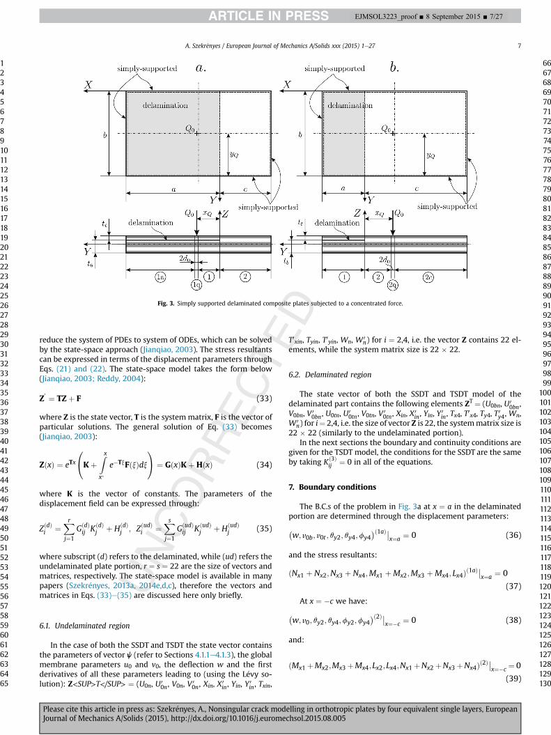
In this paper we consider laminated orthotropic plates withdifferent (L�evy type) boundary conditions and asymmetricdelamination shown in Fig. 3a and b (with simply supported edges).The plates are loaded by a concentrated force. Some of the prob-lems have been solved in some previous papers (Szekr�enyes, 2013b,2014d,b) by using the method of two ESLs. In accordance with L�evyplate formulation (Bodaghi and Saidi, 2010; Hosseini-Hashemiet al., 2011; Thai and Kim, 2012; Kapuria and Kumari, 2012) theprimary displacement parameters and the external load parameter,q in Eq. (30) are expressed by trial functions:8>><>>:
qxðx; yÞqyðx; yÞfxðx; yÞfyðx; yÞ
9>>=>>; ¼X∞n¼1
8>><>>:XnðxÞsinbyYnðxÞcosbyTxnðxÞsinbyTynðxÞcosby
9>>=>>;;
8>><>>:u0ðx; yÞv0ðx; yÞqðx; yÞwðx; yÞ
9>>=>>;¼X∞n¼1
8>><>>:U0nðxÞsinbyV0nðxÞcosbyQnðxÞsinbyWnðxÞsinby
9>>=>>; (32)
where b ¼ np/b. By taking back the solution in Eq. (32) into theequilibrium equations given by Eqs. (28)e(31) it is possible to
A. Szekr�enyes / European Journal of Mechanics A/Solids xxx (2015) 1e276
1234567891011121314151617181920212223242526272829303132333435363738394041424344454647484950515253545556575859606162636465
66676869707172737475767778798081828384858687888990919293949596979899
100101102103104105106107108109110111112113114115116117118119120121122123124125126127128129130
EJMSOL3223_proof ■ 8 September 2015 ■ 6/27
Please cite this article in press as: Szekr�enyes, A., Nonsingular crack modelling in orthotropic plates by four equivalent single layers, EuropeanJournal of Mechanics A/Solids (2015), http://dx.doi.org/10.1016/j.euromechsol.2015.08.005
reduce the system of PDEs to system of ODEs, which can be solvedby the state-space approach (Jianqiao, 2003). The stress resultantscan be expressed in terms of the displacement parameters throughEqs. (21) and (22). The state-space model takes the form below(Jianqiao, 2003; Reddy, 2004):
Z0 ¼ TZþ F (33)
where Z is the state vector, T is the systemmatrix, F is the vector ofparticular solutions. The general solution of Eq. (33) becomes(Jianqiao, 2003):
ZðxÞ ¼ eTx
0@KþZxx�
e�TxFðxÞdx1A ¼ GðxÞKþHðxÞ (34)
where K is the vector of constants. The parameters of thedisplacement field can be expressed through:
ZðdÞi ¼Xrj¼1
GðdÞij KðdÞ
j þ HðdÞj ; ZðudÞi ¼
Xsj¼1
GðudÞij KðudÞ
j þ HðudÞj (35)
where subscript (d) refers to the delaminated, while (ud) refers theundelaminated plate portion, r ¼ s ¼ 22 are the size of vectors andmatrices, respectively. The state-space model is available in manypapers (Szekr�enyes, 2013a, 2014e,d,c), therefore the vectors andmatrices in Eqs. (33)e(35) are discussed here only briefly.
6.1. Undelaminated region
In the case of both the SSDT and TSDT the state vector containsthe parameters of vector j (refer to Sections 4.1.1e4.1.3), the globalmembrane parameters u0 and v0, the deflection w and the firstderivatives of all these parameters leading to (using the L�evy so-lution): Z<SUP>T</SUP> ¼ (U0n, U0
0n, V0n, V 00n, Xin, X0
in, Yin, Y0in, Txin,
T0xin, Tyin, T0yin, Wn, W 0n) for i ¼ 2,4, i.e. the vector Z contains 22 el-
ements, while the system matrix size is 22 � 22.
6.2. Delaminated region
The state vector of both the SSDT and TSDT model of thedelaminated part contains the following elements ZT ¼ (U0bn, U0
0bn,V0bn, V 0
0bn, U0tn, U00tn, V0tn, V 0
0tn, Xin, X0in, Yin, Y
0in, Tx4, T
0x4, Ty4, T 0y4, Wn,
W 0n) for i¼ 2,4, i.e. the size of vector Z is 22, the systemmatrix size is
22 � 22 (similarly to the undelaminated portion).In the next sections the boundary and continuity conditions are
given for the TSDT model, the conditions for the SSDT are the sameby taking Kð3Þ
ij ¼ 0 in all of the equations.
7. Boundary conditions
The B.C.s of the problem in Fig. 3a at x ¼ a in the delaminatedportion are determined through the displacement parameters:�w; v0b; v0t ; qy2; qy4;fy4
�ð1aÞ��x¼a ¼ 0 (36)
and the stress resultants:
ðNx1 þ Nx2;Nx3 þ Nx4;Mx1 þMx2;Mx3 þMx4; Lx4Þð1aÞ��x¼a ¼ 0
(37)
At x ¼ �c we have:�w; v0; qy2; qy4;fy2;fy4
�ð2Þ��x¼�c ¼ 0 (38)
and:
ðMx1þMx2;Mx3þMx4;Lx2;Lx4;Nx1þNx2þNx3þNx4Þð2Þ��x¼�c ¼ 0
(39)
Fig. 3. Simply supported delaminated composite plates subjected to a concentrated force.
A. Szekr�enyes / European Journal of Mechanics A/Solids xxx (2015) 1e27 7
1234567891011121314151617181920212223242526272829303132333435363738394041424344454647484950515253545556575859606162636465
66676869707172737475767778798081828384858687888990919293949596979899
100101102103104105106107108109110111112113114115116117118119120121122123124125126127128129130
EJMSOL3223_proof ■ 8 September 2015 ■ 7/27
Please cite this article in press as: Szekr�enyes, A., Nonsingular crack modelling in orthotropic plates by four equivalent single layers, EuropeanJournal of Mechanics A/Solids (2015), http://dx.doi.org/10.1016/j.euromechsol.2015.08.005
8. Continuity conditions between regions (1) and (2)
The conditions between regions (1) and (2) (refer to Fig. 3a)involves the continuity of the displacement parameters and stressresultants. In the sequel, these conditions are discussed separately.
8.1. Continuity of stress resultants
To define the continuity conditions the equivalent stress re-sultants can be defined based on the equilibrium equations (Eqs.(28) and (29)) and (31) and the vectors given by Eqs. (25) and (26):
cMðx;xyÞð1Þ12 ¼
Xj¼1;2
��Kð0Þj1 þ Kð0Þ
j2
�Nðx;xyÞj þ
�Kð1Þj1 þ Kð1Þ
j2
�Mðx;xyÞ
j
þ�Kð2Þj1 þ Kð2Þ
j2
�Lðx;xyÞj þ
�Kð3Þj1 þ Kð3Þ
j2
�Pðx;xyÞj
�ð1Þ(40)
cMðx;xyÞð1Þ34 ¼
Xj¼3;4
��Kð0Þj1 þ Kð0Þ
j2
�Nðx;xyÞj þ
�Kð1Þj1 þ Kð1Þ
j2
�Mðx;xyÞ
j
þ�Kð2Þj1 þ Kð2Þ
j2
�Lðx;xyÞj þ
�Kð3Þj1 þ Kð3Þ
j2
�Pðx;xyÞj
�ð1Þ(41)
bLðx;xyÞð1Þ1234 ¼
Xj¼1::4
�Kð0Þj3 Nðx;xyÞ
j þ Kð1Þj3 Mðx;xyÞð1Þ
j þ Kð2Þj3 Lðx;xyÞj
þ Kð3Þj3 Pðx;xyÞ
j
�ð1Þ(42)
for the delaminated portion (1), wherecM12 andcM34 are the vectorsof equivalent bending/twisting moments, bL1234 is the vector ofequivalent higher-order stress resultants. Moreover, for the unde-laminated region (2) we have:
cMðx;xyÞð2Þ12 ¼
Xj¼1;2
��Kð0Þj1 þ Kð0Þ
j3
�Nðx;xyÞj þ
�Kð1Þj1 þ Kð1Þ
j3
�Mðx;xyÞ
j
þ�Kð2Þj1 þ Kð2Þ
j3
�Lðx;xyÞj þ
�Kð3Þj1 þ Kð3Þ
j3
�Pðx;xyÞj
�ð2Þ(43)
cMðx;xyÞð2Þ34 ¼
Xj¼3;4
��Kð0Þj1 þ Kð0Þ
j3
�Nðx;xyÞj þ
�Kð1Þj1 þ Kð1Þ
j3
�Mðx;xyÞ
j
þ�Kð2Þj1 þ Kð2Þ
j3
�Lðx;xyÞj þ
�Kð3Þj1 þ Kð3Þ
j3
�Pðx;xyÞj
�ð2Þ(44)
bLðx;xyÞð2Þ12 ¼
Xj¼1;2
��Kð0Þj2 þ Kð0Þ
j4
�Nðx;xyÞj þ
�Kð1Þj2 þ Kð1Þ
j4
�Mðx;xyÞ
j
þ�Kð2Þj2 þ Kð2Þ
j4
�Lðx;xyÞj þ
�Kð3Þj2 þ Kð3Þ
j4
�Pðx;xyÞj
�ð2Þ(45)
bLðx;xyÞð2Þ34 ¼
Xj¼3;4
��Kð0Þj2 þ Kð0Þ
j4
�Nðx;xyÞj þ
�Kð1Þj2 þ Kð1Þ
j4
�Mðx;xyÞ
j
þ�Kð2Þj2 þ Kð2Þ
j4
�Lðx;xyÞj þ
�Kð3Þj2 þ Kð3Þ
j4
�Pðx;xyÞj
�ð2Þ(46)
The continuity conditions using the equivalent stress resultantsare: cMðx;xyÞ
12 ;cMðx;xyÞ34 ; bLðx;xyÞ1234 ;
Xi¼1::4
Nðx;xyÞi
!�����ð1Þ
x¼�0
¼ cMðx;xyÞ
12 ;cMðx;xyÞ34 ; bLðx;xyÞ
12 þ bLðx;xyÞ34 ;
Xi¼1::4
Nðx;xyÞi
!�����ð2Þ
x¼þ0
(47)
8.2. Continuity of displacement parameters
In the case of the general TSDT the continuity of the in-planedisplacement is ensured only if the constant, linear, quadratic andcubic terms are exactly the same in the delamination front (x ¼ 0).Because of the parameter elimination based on the SEKC it is notpossible to match directly the constant, quadratic and cubic termsin the displacement function from layer by layer. Only the conti-nuity of primary parameters can be defined between each ESL. Inspite of that the continuity of the remaining membrane, linear,quadratic and cubic terms can be ensured indirectly (automatically)if certain conditions are met. The requirements of automatic con-tinuity is formulated in the form of a theorem. We define thefollowing set of parameters:
ga ¼�wn;w
0n; qx2; qy2; qx4; qy4;fx4;fy4
�(48)
which contains the deflection, slope and the mutual primary pa-rameters. The total continuity of the displacement functions in-volves the following necessary conditions:
gð1Þa
��x¼þ0 ¼ gð2Þa
��x¼�0 (49)
However these are not sufficient. The sufficient conditions arepresented through a theorem.
8.2.1. The theorem of autocontinuity (AC theorem)Theorem: If the displacement field in the form of Eq. (14) in a
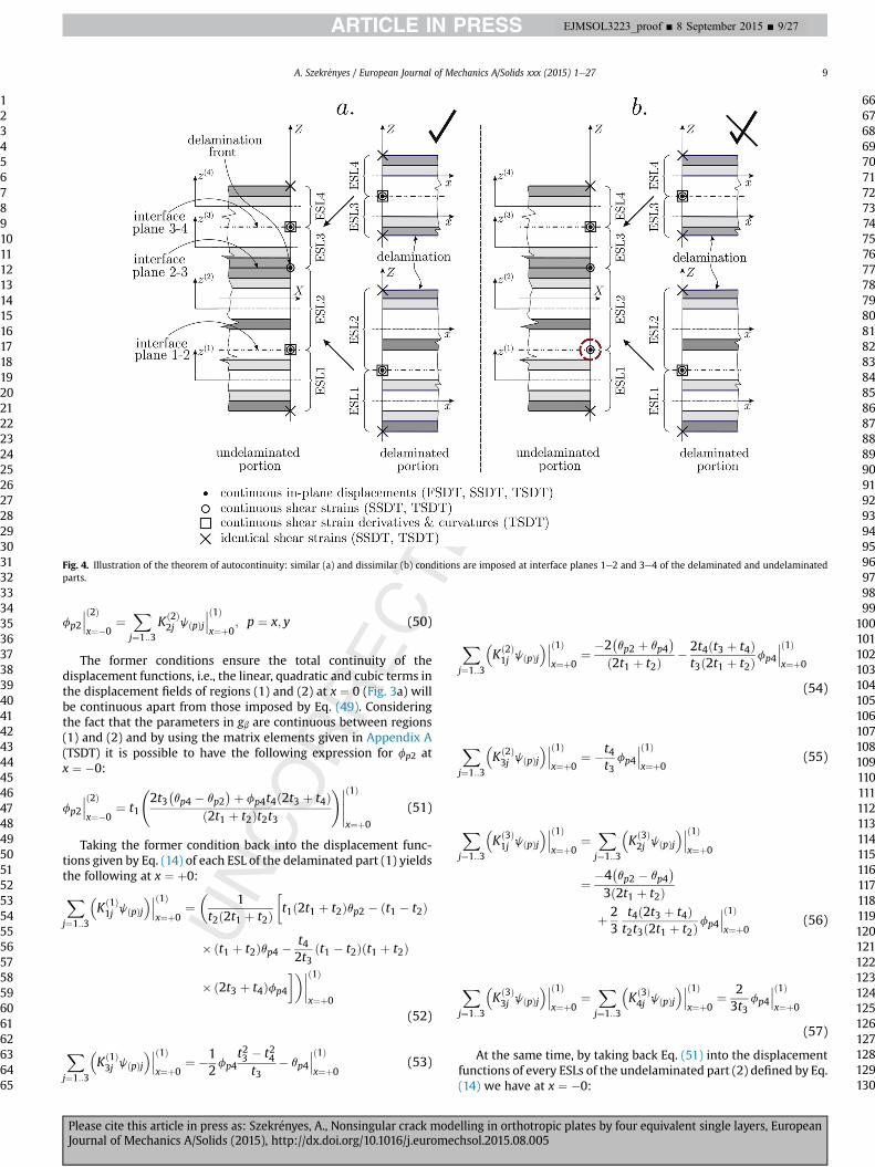
laminated plate with delamination is developed by using the SEKCrequirements and Nd2ℕ and Nud2ℕ are the numbers of eliminatedparameters in the delaminated and undelaminated parts, respec-tively, and Nd s Nud, then the total continuity of the first-, second-and third-order terms in the in-plane displacement functions of eachESL in the delaminated and undelaminated plate parts e apart fromthose imposed by Eq. (48) (mutual primary parameters) e can beensured by imposing the continuity of jNd � Nudj2ℕ number ofparameters. These parameters are the autocontinuity (or simply AC)parameters, which are at the same time primary parameters too. Theautocontinuity is satisfied only if along interfaces 1e2 and 3e4 andat the plate boundaries (Figs. 1 and 2) the same conditions areimposed in the delaminated and undelaminated portions. Along thedelamination plane (interface 2e3) different conditions can beapplied. Fig. 4a shows the casewhen the autocontinuity between thedelaminated and undelaminated parts is satisfied, Fig. 4b indicates acase when dissimilar conditions are imposed at interface 1e2 lead-ing to discontinuous displacement field in the bottom plates.
Proof: In the case of the TSDT model Nd ¼ 26, Nud ¼ 24 (refer toSections 4.1.1 and 4.2.1), thus the number of AC parameters isjNd � Nudj ¼ 2. The AC parameters can be assigned based on thevector of primary parameters: the comparison of the j(p) vectors inSections 4.1.1 and 4.2.1 reveals that the AC parameters are fx2 andfy2 in the undelaminated region (2). The comparison of thedisplacement field (Eq. (14)) for the undelaminated and delami-nated regions (Appendix A) reveals the following sufficientconditions:
A. Szekr�enyes / European Journal of Mechanics A/Solids xxx (2015) 1e278
1234567891011121314151617181920212223242526272829303132333435363738394041424344454647484950515253545556575859606162636465
66676869707172737475767778798081828384858687888990919293949596979899
100101102103104105106107108109110111112113114115116117118119120121122123124125126127128129130
EJMSOL3223_proof ■ 8 September 2015 ■ 8/27
Please cite this article in press as: Szekr�enyes, A., Nonsingular crack modelling in orthotropic plates by four equivalent single layers, EuropeanJournal of Mechanics A/Solids (2015), http://dx.doi.org/10.1016/j.euromechsol.2015.08.005
fp2
���ð2Þx¼�0
¼Xj¼1::3
Kð2Þ2j jðpÞj
���ð1Þx¼þ0
; p ¼ x; y (50)
The former conditions ensure the total continuity of thedisplacement functions, i.e., the linear, quadratic and cubic terms inthe displacement fields of regions (1) and (2) at x ¼ 0 (Fig. 3a) willbe continuous apart from those imposed by Eq. (49). Consideringthe fact that the parameters in gb are continuous between regions(1) and (2) and by using the matrix elements given in Appendix A(TSDT) it is possible to have the following expression for fp2 atx ¼ �0:
fp2
���ð2Þx¼�0
¼ t1
2t3�qp4 � qp2
�þ fp4t4ð2t3 þ t4Þð2t1 þ t2Þt2t3
!�����ð1Þ
x¼þ0
(51)
Taking the former condition back into the displacement func-tions given by Eq. (14) of each ESL of the delaminated part (1) yieldsthe following at x ¼ þ0:Xj¼1::3
�Kð1Þ1j jðpÞj
����ð1Þx¼þ0
¼�
1t2ð2t1 þ t2Þ
t1ð2t1 þ t2Þqp2 � ðt1 � t2Þ
� ðt1 þ t2Þqp4 �t42t3
ðt1 � t2Þðt1 þ t2Þ
� ð2t3 þ t4Þfp4
������ð1Þx¼þ0
(52)
Xj¼1::3
�Kð1Þ3j jðpÞj
����ð1Þx¼þ0
¼ �12fp4
t23 � t24t3
� qp4
���ð1Þx¼þ0
(53)
Xj¼1::3
�Kð2Þ1j jðpÞj
����ð1Þx¼þ0
¼ �2�qp2 þ qp4
�ð2t1 þ t2Þ
� 2t4ðt3 þ t4Þt3ð2t1 þ t2Þ
fp4
���ð1Þx¼þ0
(54)
Xj¼1::3
�Kð2Þ3j jðpÞj
����ð1Þx¼þ0
¼ �t4t3fp4
���ð1Þx¼þ0
(55)
Xj¼1::3
�Kð3Þ1j jðpÞj
����ð1Þx¼þ0
¼Xj¼1::3
�Kð3Þ2j jðpÞj
����ð1Þx¼þ0
¼ �4�qp2 � qp4
�3ð2t1 þ t2Þ
þ 23
t4ð2t3 þ t4Þt2t3ð2t1 þ t2Þ
fp4
���ð1Þx¼þ0
(56)
Xj¼1::3
�Kð3Þ3j jðpÞj
����ð1Þx¼þ0
¼Xj¼1::3
�Kð3Þ4j jðpÞj
����ð1Þx¼þ0
¼ 23t3
fp4
���ð1Þx¼þ0
(57)
At the same time, by taking back Eq. (51) into the displacementfunctions of every ESLs of the undelaminated part (2) defined by Eq.(14) we have at x ¼ �0:
Fig. 4. Illustration of the theorem of autocontinuity: similar (a) and dissimilar (b) conditions are imposed at interface planes 1e2 and 3e4 of the delaminated and undelaminatedparts.
A. Szekr�enyes / European Journal of Mechanics A/Solids xxx (2015) 1e27 9
1234567891011121314151617181920212223242526272829303132333435363738394041424344454647484950515253545556575859606162636465
66676869707172737475767778798081828384858687888990919293949596979899
100101102103104105106107108109110111112113114115116117118119120121122123124125126127128129130
EJMSOL3223_proof ■ 8 September 2015 ■ 9/27
Please cite this article in press as: Szekr�enyes, A., Nonsingular crack modelling in orthotropic plates by four equivalent single layers, EuropeanJournal of Mechanics A/Solids (2015), http://dx.doi.org/10.1016/j.euromechsol.2015.08.005

Xj¼1::4
�Kð1Þ1j jðpÞj
����ð2Þx¼�0
¼�
1t2ð2t1 þ t2Þ
t1ð2t1 þ t2Þqp2 � ðt1 � t2Þ
� ðt1 þ t2Þqp4 �t42t3
ðt1 � t2Þðt1 þ t2Þ
� ð2t3 þ t4Þfp4
������ð2Þx¼�0
(58)
Xj¼1::4
�Kð1Þ3j jðpÞj
����ð2Þx¼�0
¼ �12fp4
t23 � t24t3
� qp4
���ð2Þx¼�0
(59)
Xj¼1::4
�Kð2Þ1j jðpÞj
����ð2Þx¼�0
¼ �2�qp2 þ qp4
�ð2t1 þ t2Þ
� 2t4ðt3 þ t4Þt3ð2t1 þ t2Þ
fp4
���ð2Þx¼�0
(60)
Xj¼1::4
�Kð2Þ3j jðpÞj
����ð2Þx¼�0
¼ �t4t3fp4
���ð2Þx¼�0
(61)
Xj¼1::4
�Kð3Þ1j jðpÞj
����ð2Þx¼�0
¼Xj¼1::3
�Kð3Þ2j j
�ðpÞj����ð2Þ
x¼�0
¼ �4�qp2 � qp4
�3ð2t1 þ t2Þ
þ 23
t4ð2t3 þ t4Þt2t3ð2t1 þ t2Þ
fp4
���ð2Þx¼�0
(62)
The left-hand sides of Eqs. (52)e(62) define the values of q(p)1,q(p)3, f(p)1, f(p)3, l(p)1, l(p)2, l(p)3 and l(p)4, i.e. the secondary param-eters. Obviously, The right-hand sides of Eqs. (52)e(57) and Eqs.(58)e(62) are the same in pairs, and more importantly determinedin terms of the primary parameters. Considering the continuity ofthe parameters in Eq. (48) by Eq. (49) it can be seen that the con-tinuity of the linear, quadratic and cubic terms in the displacementfunctions of regions (1) and (2) are automatically satisfied if Eq. (51)is utilized.
Consequence: If the continuity of linear terms (q rotations) in thedisplacement field in each ESL are continuous, moreover the con-tinuity of quadratic and cubic terms of each ESL are imposed usingthe AC parameters, then the continuity of the membrane displace-ment components between the top plates (as well as the bottomplates) of the delaminated and undelaminated regions can beensured by imposing the equality between the membrane (con-stant) displacement terms of only a single ESL in the delaminatedpart and a single one in the undelaminated part, but not in everyESLs. The ESLs can be chosen optionally, however the chosen ESLsshould be in the same through-thickness position in the delami-nated and undelaminated plate regions. In this case the continuityof the membrane parts in the other ESLs is satisfied automatically.We choose the first (in the bottom layer) and third (in top layer)ESLs to impose the continuity of the membrane displacementsusing the equations below:�u0bv0b
�þ P
j¼1::3Kð0Þ1j
�jðxÞjjðyÞj
�����ð1Þx¼þ0
¼�u0v0
�þXj¼1::4
Kð0Þ1j
�jðxÞjjðyÞj
�����ð2Þx¼�0�
u0tv0t
� Pj¼1::3
Kð0Þ3j
�jðxÞjjðyÞj
�����ð1Þx¼þ0
¼�u0v0
�þXj¼1::4
Kð0Þ3j
�jðxÞjjðyÞj
�����ð2Þx¼�0
(63)
The autocontinuity theorem is also valid for the SSDT. The onlydifference is that the Kð3Þ
ij constants are zero.
9. Continuity between regions (1)-(1q) and (1q)-(1a)
The continuity between regions (1)-(1q) and (1q)-(1a) (seeFig. 3a) can be imposed by defining the sets of parameters below:
gb ¼�u0b;u0t ; v0b; v0t ;wn;w
0n; qx2; qy2; qx4; qy4;fx4;fy4
�(64)
gg ¼ cMðx;xyÞ
12 ;cMðx;xyÞ34 ; bLðx;xyÞ1234 ;
Xi¼1::2
Nðx;xyÞi ;
Xi¼3::4
Nðx;xyÞi
!(65)
The continuity conditions are (refer to Fig. 3a):
gð1Þb
��x¼x0�d0
¼ gð1qÞb
��x¼x0�d0
; gð1Þg
��x¼x0�d0
¼ gð1qÞg
��x¼x0�d0
(66)
gð1qÞb
��x¼x0þd0
¼ gð1aÞb
��x¼x0þd0
; gð1qÞg
��x¼x0þd0
¼ gð1aÞg
��x¼x0þd0
(67)
The summary of the equations results in: Eqs. (36)e(39) mean22 B.C.s, Eqs. (49), (51) and (63) yield 22 conditions between re-gions (1) and (2). Eqs. (66) and (67) provide 2 � 22 conditions. Thatmeans 22 þ 22þ22 þ 22 ¼ 88 conditions altogether in the case ofproblem a in Fig. 3. Problem b in Fig. 3 can be solved similarly,therefore the details are not given. The B.C.s and the C.C.s for theSSDT model can be defined similarly, in these cases the constantsKð3Þij ¼ 0 in Eq. (14) and in the stress resultants.It has to be mentioned that although mathematically it is
possible to impose traction-free conditions to the plate boundaries(similarly to Reddy theory), but this makes the model over-con-strained. Over-constraining means, that mechanically the modelbecomes too stiff and the bad estimation of the stress field in thetransition zone between (1) and (2) takes place. The reason for thebad description of the mechanical problem is that there are notenough conditions to impose the continuity of the primary pa-rameters, the membrane displacements and the correspondingstress resultants. In this respect the models proposed in this paperare well-constrained models.
10. J-integral
The J-integral (Rice, 1968; Cherepanov, 1997) for SSDT and TSDThas already been derived for plates with symmetric (Szekr�enyes,2013a, 2014e, 2014a, 2014c) and asymmetric (Szekr�enyes, 2013b,2014d, 2014b) lay-up. Therefore, in this work the details are notdiscussed. The mode-II and mode-III J-integrals (JII ¼ GII, JIII ¼ GIII)are given in Appendix C.
11. Results and discussions
To demonstrate the performance of the analytical models theexamples shown in Fig. 3 are solved. The data of the problemdepicted in Fig. 3a are: a ¼ 105 mm (delamination length),c ¼ 55 mm (undelaminated length), b ¼ 160 mm (plate width),tt þ tb ¼ 4.5 mm (plate thickness), Q0 ¼ 1000 N, xQ ¼ 31 mm,yQ ¼ 50 mm and yQ ¼ 80 mm (point of action coordinates of Q0),d0 ¼ 0.1 mm. For the problem in Fig. 3b the data are: a ¼ 55 mm(delamination length), c ¼ 35 mm (undelaminated length),b ¼ 90 mm (plate width), tt þ tb ¼ 4.5 mm (plate thickness),Q0 ¼ 10000 N, xQ ¼ 11 mm, yQ ¼ 30 mm and yQ ¼ 45 mm (point ofaction coordinates of Q0), d0 ¼ 0.1 mm. The problem was solved byreplacing the concentrated load by distributed force on the distance2d0. The details can be found in (Szekr�enyes, 2014d). Thematerial ofthe plates is carbon/epoxy. The lay-up of the plate is½±45f =0=±45f2=0�S, the material properties can be found in(Szekr�enyes, 2014d). Finite element models were also constructed
A. Szekr�enyes / European Journal of Mechanics A/Solids xxx (2015) 1e2710
1234567891011121314151617181920212223242526272829303132333435363738394041424344454647484950515253545556575859606162636465
66676869707172737475767778798081828384858687888990919293949596979899
100101102103104105106107108109110111112113114115116117118119120121122123124125126127128129130
EJMSOL3223_proof ■ 8 September 2015 ■ 10/27
Please cite this article in press as: Szekr�enyes, A., Nonsingular crack modelling in orthotropic plates by four equivalent single layers, EuropeanJournal of Mechanics A/Solids (2015), http://dx.doi.org/10.1016/j.euromechsol.2015.08.005
to validate the analytical results. The details of the FE models arepresented in a recent paper (Szekr�enyes, 2014d). The delaminationtip elements and the global mesh resolution were chosen inaccordance with recommendations of the literature (Raju et al.,1988; Johnston et al., 2014; Mehrabadi, 2014) The position of thedelamination was varied in the through thickness direction, thesewere assigned as cases I, II, III and IV (Szekr�enyes, 2014d). Theproblems are solved for some selected cases and different boundaryconditions.
11.1. Displacement and stress distributions
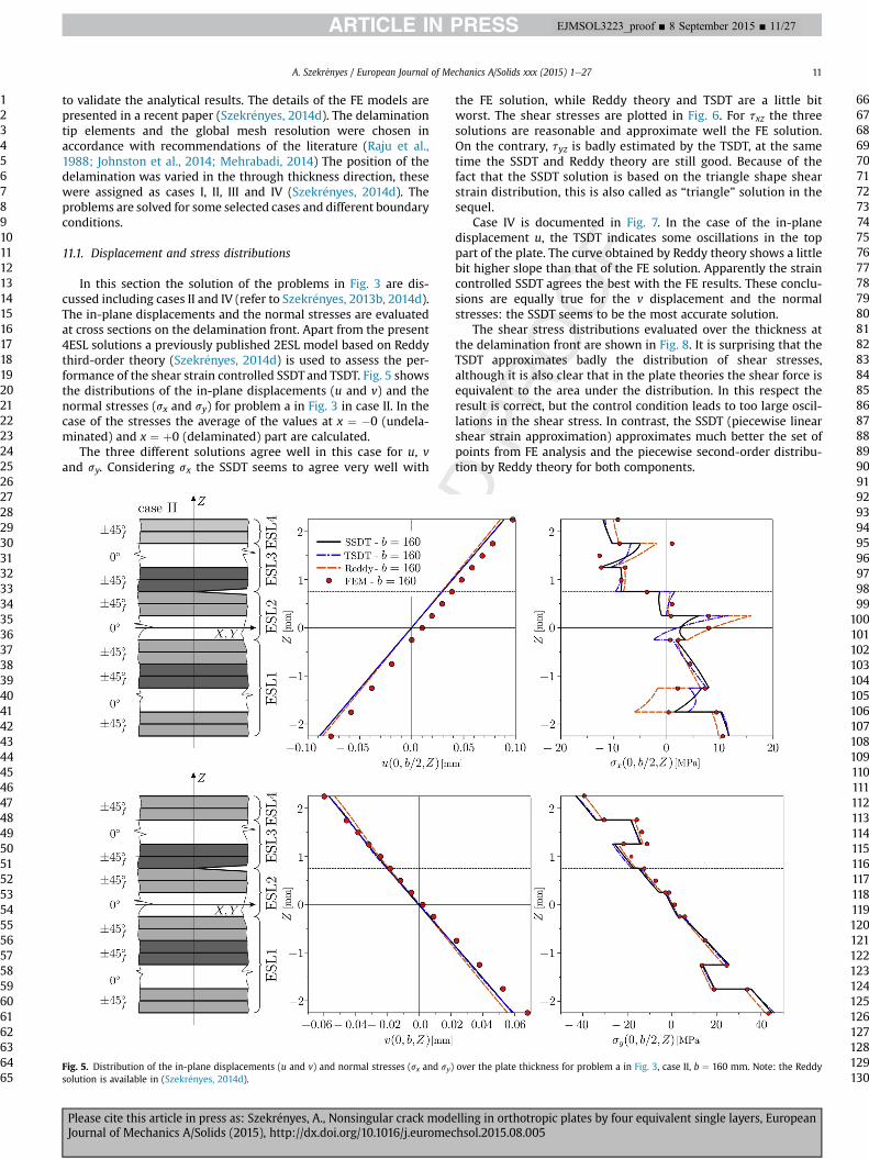
In this section the solution of the problems in Fig. 3 are dis-cussed including cases II and IV (refer to Szekr�enyes, 2013b, 2014d).The in-plane displacements and the normal stresses are evaluatedat cross sections on the delamination front. Apart from the present4ESL solutions a previously published 2ESL model based on Reddythird-order theory (Szekr�enyes, 2014d) is used to assess the per-formance of the shear strain controlled SSDT and TSDT. Fig. 5 showsthe distributions of the in-plane displacements (u and v) and thenormal stresses (sx and sy) for problem a in Fig. 3 in case II. In thecase of the stresses the average of the values at x ¼ �0 (undela-minated) and x ¼ þ0 (delaminated) part are calculated.
The three different solutions agree well in this case for u, vand sy. Considering sx the SSDT seems to agree very well with
the FE solution, while Reddy theory and TSDT are a little bitworst. The shear stresses are plotted in Fig. 6. For txz the threesolutions are reasonable and approximate well the FE solution.On the contrary, tyz is badly estimated by the TSDT, at the sametime the SSDT and Reddy theory are still good. Because of thefact that the SSDT solution is based on the triangle shape shearstrain distribution, this is also called as “triangle” solution in thesequel.
Case IV is documented in Fig. 7. In the case of the in-planedisplacement u, the TSDT indicates some oscillations in the toppart of the plate. The curve obtained by Reddy theory shows a littlebit higher slope than that of the FE solution. Apparently the straincontrolled SSDT agrees the best with the FE results. These conclu-sions are equally true for the v displacement and the normalstresses: the SSDT seems to be the most accurate solution.
The shear stress distributions evaluated over the thickness atthe delamination front are shown in Fig. 8. It is surprising that theTSDT approximates badly the distribution of shear stresses,although it is also clear that in the plate theories the shear force isequivalent to the area under the distribution. In this respect theresult is correct, but the control condition leads to too large oscil-lations in the shear stress. In contrast, the SSDT (piecewise linearshear strain approximation) approximates much better the set ofpoints from FE analysis and the piecewise second-order distribu-tion by Reddy theory for both components.
Fig. 5. Distribution of the in-plane displacements (u and v) and normal stresses (sx and sy) over the plate thickness for problem a in Fig. 3, case II, b ¼ 160 mm. Note: the Reddysolution is available in (Szekr�enyes, 2014d).
A. Szekr�enyes / European Journal of Mechanics A/Solids xxx (2015) 1e27 11
1234567891011121314151617181920212223242526272829303132333435363738394041424344454647484950515253545556575859606162636465
66676869707172737475767778798081828384858687888990919293949596979899
100101102103104105106107108109110111112113114115116117118119120121122123124125126127128129130
EJMSOL3223_proof ■ 8 September 2015 ■ 11/27
Please cite this article in press as: Szekr�enyes, A., Nonsingular crack modelling in orthotropic plates by four equivalent single layers, EuropeanJournal of Mechanics A/Solids (2015), http://dx.doi.org/10.1016/j.euromechsol.2015.08.005

Fig. 6. Distribution shear stresses (txz and tyz) over the plate thickness for problem a in Fig. 3, case II, b ¼ 160 mm. Note: the Reddy solution is available in (Szekr�enyes, 2014d).
Fig. 7. Distribution of the in-plane displacements (u and v) and normal stresses (sx and sy) over the plate thickness for problem a in Fig. 3, case IV, b ¼ 160 mm. Note: the Reddysolution is available in (Szekr�enyes, 2014d).
A. Szekr�enyes / European Journal of Mechanics A/Solids xxx (2015) 1e2712
1234567891011121314151617181920212223242526272829303132333435363738394041424344454647484950515253545556575859606162636465
66676869707172737475767778798081828384858687888990919293949596979899
100101102103104105106107108109110111112113114115116117118119120121122123124125126127128129130
EJMSOL3223_proof ■ 8 September 2015 ■ 12/27
Please cite this article in press as: Szekr�enyes, A., Nonsingular crack modelling in orthotropic plates by four equivalent single layers, EuropeanJournal of Mechanics A/Solids (2015), http://dx.doi.org/10.1016/j.euromechsol.2015.08.005

Fig. 8. Distribution shear stresses (txz and tyz) over the plate thickness for problem a in Fig. 3, case IV, b ¼ 160 mm. Note: the Reddy solution is available in (Szekr�enyes, 2014d).
Fig. 9. Distribution of the in-plane displacements (u and v) and normal stresses (sx and sy) over the plate thickness for problem b in Fig. 3, case II, b ¼ 90 mm. Note: the Reddysolution is available in (Szekr�enyes, 2014d).
A. Szekr�enyes / European Journal of Mechanics A/Solids xxx (2015) 1e27 13
1234567891011121314151617181920212223242526272829303132333435363738394041424344454647484950515253545556575859606162636465
66676869707172737475767778798081828384858687888990919293949596979899
100101102103104105106107108109110111112113114115116117118119120121122123124125126127128129130
EJMSOL3223_proof ■ 8 September 2015 ■ 13/27
Please cite this article in press as: Szekr�enyes, A., Nonsingular crack modelling in orthotropic plates by four equivalent single layers, EuropeanJournal of Mechanics A/Solids (2015), http://dx.doi.org/10.1016/j.euromechsol.2015.08.005
The results of problem b (Fig. 3b) are documented in Figs. 9e12.This example involves smaller plate dimensions and since the pointof action of the force is closer to the delamination front, higherinfluence of the load on the fields is experienced. In case II (Fig. 9) it
is apparent that the displacement component u is perturbatedmore intensively than in problem a. The highest oscillations areprovided by the TSDT, while the SSDT and Reddy theory give betteragreement with the FE results. The stresses are approximated with
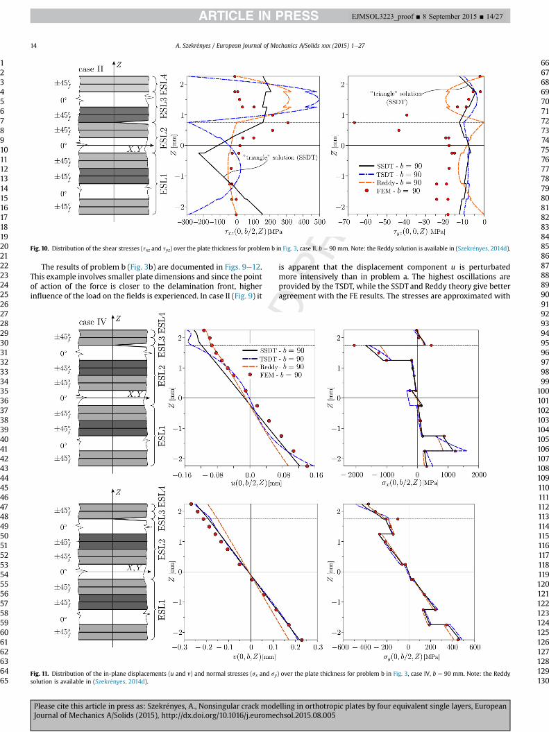
Fig. 10. Distribution of the shear stresses (txz and tyz) over the plate thickness for problem b in Fig. 3, case II, b ¼ 90 mm. Note: the Reddy solution is available in (Szekr�enyes, 2014d).
Fig. 11. Distribution of the in-plane displacements (u and v) and normal stresses (sx and sy) over the plate thickness for problem b in Fig. 3, case IV, b ¼ 90 mm. Note: the Reddysolution is available in (Szekr�enyes, 2014d).
A. Szekr�enyes / European Journal of Mechanics A/Solids xxx (2015) 1e2714
1234567891011121314151617181920212223242526272829303132333435363738394041424344454647484950515253545556575859606162636465
66676869707172737475767778798081828384858687888990919293949596979899
100101102103104105106107108109110111112113114115116117118119120121122123124125126127128129130
EJMSOL3223_proof ■ 8 September 2015 ■ 14/27
Please cite this article in press as: Szekr�enyes, A., Nonsingular crack modelling in orthotropic plates by four equivalent single layers, EuropeanJournal of Mechanics A/Solids (2015), http://dx.doi.org/10.1016/j.euromechsol.2015.08.005
similar accuracy by each theory. In Fig. 10 the shear stresses areplotted. The SSDT and Reddy theory is better again than the TSDTfor txz. By each solution the shear stress tyz disagrees with the FEresults.
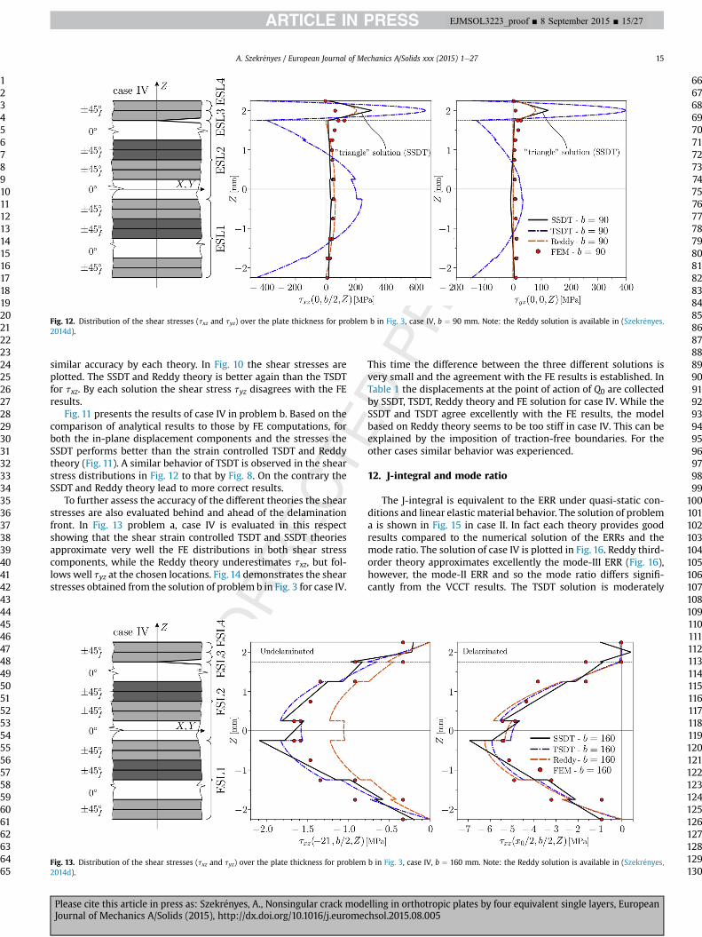
Fig. 11 presents the results of case IV in problem b. Based on thecomparison of analytical results to those by FE computations, forboth the in-plane displacement components and the stresses theSSDT performs better than the strain controlled TSDT and Reddytheory (Fig. 11). A similar behavior of TSDT is observed in the shearstress distributions in Fig. 12 to that by Fig. 8. On the contrary theSSDT and Reddy theory lead to more correct results.
To further assess the accuracy of the different theories the shearstresses are also evaluated behind and ahead of the delaminationfront. In Fig. 13 problem a, case IV is evaluated in this respectshowing that the shear strain controlled TSDT and SSDT theoriesapproximate very well the FE distributions in both shear stresscomponents, while the Reddy theory underestimates txz, but fol-lows well tyz at the chosen locations. Fig. 14 demonstrates the shearstresses obtained from the solution of problem b in Fig. 3 for case IV.
This time the difference between the three different solutions isvery small and the agreement with the FE results is established. InTable 1 the displacements at the point of action of Q0 are collectedby SSDT, TSDT, Reddy theory and FE solution for case IV. While theSSDT and TSDT agree excellently with the FE results, the modelbased on Reddy theory seems to be too stiff in case IV. This can beexplained by the imposition of traction-free boundaries. For theother cases similar behavior was experienced.
12. J-integral and mode ratio
The J-integral is equivalent to the ERR under quasi-static con-ditions and linear elastic material behavior. The solution of problema is shown in Fig. 15 in case II. In fact each theory provides goodresults compared to the numerical solution of the ERRs and themode ratio. The solution of case IV is plotted in Fig. 16. Reddy third-order theory approximates excellently the mode-III ERR (Fig. 16),however, the mode-II ERR and so the mode ratio differs signifi-cantly from the VCCT results. The TSDT solution is moderately
Fig. 12. Distribution of the shear stresses (txz and tyz) over the plate thickness for problem b in Fig. 3, case IV, b ¼ 90 mm. Note: the Reddy solution is available in (Szekr�enyes,2014d).
Fig. 13. Distribution of the shear stresses (txz and tyz) over the plate thickness for problem b in Fig. 3, case IV, b ¼ 160 mm. Note: the Reddy solution is available in (Szekr�enyes,2014d).
A. Szekr�enyes / European Journal of Mechanics A/Solids xxx (2015) 1e27 15
1234567891011121314151617181920212223242526272829303132333435363738394041424344454647484950515253545556575859606162636465
66676869707172737475767778798081828384858687888990919293949596979899
100101102103104105106107108109110111112113114115116117118119120121122123124125126127128129130
EJMSOL3223_proof ■ 8 September 2015 ■ 15/27
Please cite this article in press as: Szekr�enyes, A., Nonsingular crack modelling in orthotropic plates by four equivalent single layers, EuropeanJournal of Mechanics A/Solids (2015), http://dx.doi.org/10.1016/j.euromechsol.2015.08.005
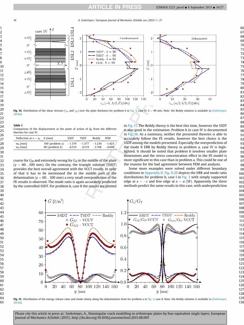
coarse for GIII and extremely wrong for GII in the middle of the plate(y ¼ 60…100 mm). On the contrary, the triangle solution (SSDT)provides the best overall agreement with the VCCT results. In spiteof that it has to be mentioned the in the middle part of thedelamination (y ¼ 60…100 mm) a very small overprediction of theFE results is observed. The mode ratio is again accurately predictedby the controlled SSDT. For problem b, case II the results are plotted
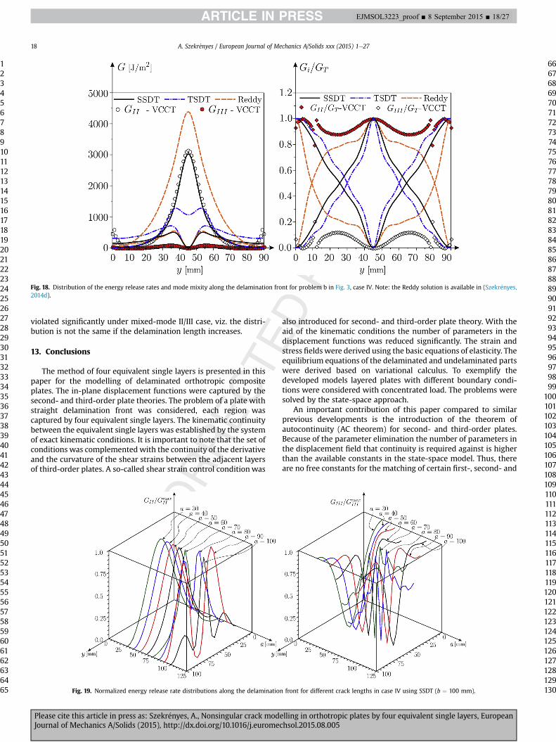
in Fig. 17. The Reddy theory is the best this time, however the SSDTis also good in the estimation. Problem b in case IV is documentedin Fig. 18. As a summary, neither the presented theories is able toaccurately follow the FE results, however the best choice is theSSDT among the models presented. Especially the overprediction ofthe mode II ERR by Reddy theory in problem a, case IV is high-lighted. It should be noted that problem b involves smaller platedimensions and the stress concentration effect in the FE model ismore significant in this case than in problem a. This could be one ofthe reasons for the bad agreement between FEM and analysis.
Some more examples were solved under different boundaryconditions in Appendix D. Fig. D.20 depicts the ERR and mode ratiodistributions for problem b, case I in Fig. 3 with simply supportededge at x ¼ �c and free edge at x ¼ a (SF). Apparently the threemethods predict the same results in this case, with underprediction
Table 1Comparison of the displacement at the point of action of Q0 from the differenttheories for case IV.
Deflection at x ¼ x0 b [mm] SSDT TSDT Reddy FEM
w0 [mm] 160 (problem a) �1.379 �1.377 �1.234 �1.423w0 [mm] 90 (problem b) �4.519 �4.519 �3.768 �4.699
Fig. 14. Distribution of the shear stresses (txz and tyz) over the plate thickness for problem b in Fig. 3, case IV, b ¼ 90 mm. Note: the Reddy solution is available in (Szekr�enyes,2014d).
Fig. 15. Distribution of the energy release rates and mode mixity along the delamination front for problem a in Fig. 3, case II. Note: the Reddy solution is available in (Szekr�enyes,2014d).
A. Szekr�enyes / European Journal of Mechanics A/Solids xxx (2015) 1e2716
1234567891011121314151617181920212223242526272829303132333435363738394041424344454647484950515253545556575859606162636465
66676869707172737475767778798081828384858687888990919293949596979899
100101102103104105106107108109110111112113114115116117118119120121122123124125126127128129130
EJMSOL3223_proof ■ 8 September 2015 ■ 16/27
Please cite this article in press as: Szekr�enyes, A., Nonsingular crack modelling in orthotropic plates by four equivalent single layers, EuropeanJournal of Mechanics A/Solids (2015), http://dx.doi.org/10.1016/j.euromechsol.2015.08.005
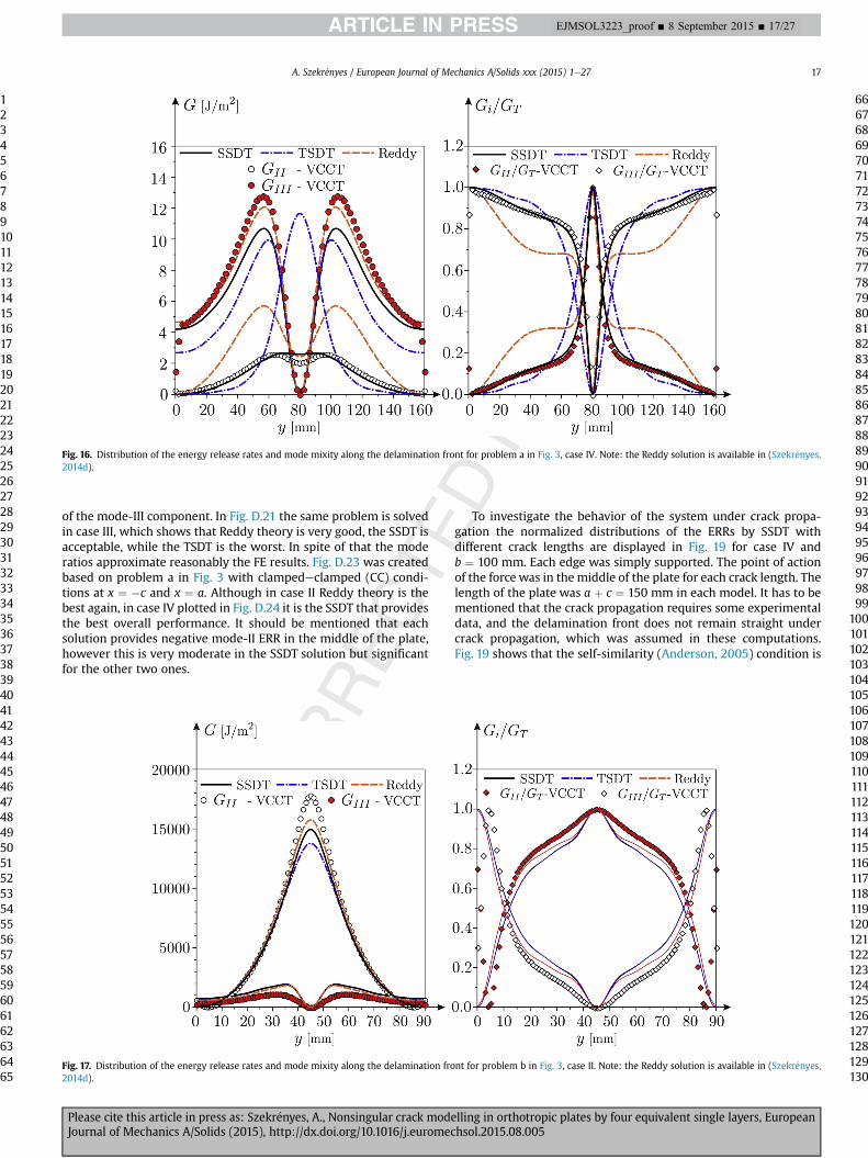
of the mode-III component. In Fig. D.21 the same problem is solvedin case III, which shows that Reddy theory is very good, the SSDT isacceptable, while the TSDT is the worst. In spite of that the moderatios approximate reasonably the FE results. Fig. D.23 was createdbased on problem a in Fig. 3 with clampedeclamped (CC) condi-tions at x ¼ �c and x ¼ a. Although in case II Reddy theory is thebest again, in case IV plotted in Fig. D.24 it is the SSDT that providesthe best overall performance. It should be mentioned that eachsolution provides negative mode-II ERR in the middle of the plate,however this is very moderate in the SSDT solution but significantfor the other two ones.
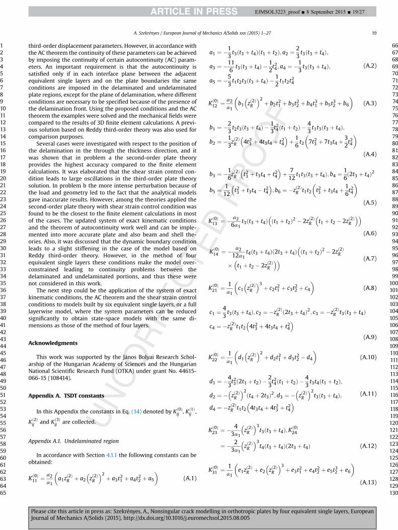
To investigate the behavior of the system under crack propa-gation the normalized distributions of the ERRs by SSDT withdifferent crack lengths are displayed in Fig. 19 for case IV andb ¼ 100 mm. Each edge was simply supported. The point of actionof the force was in themiddle of the plate for each crack length. Thelength of the plate was a þ c ¼ 150 mm in each model. It has to bementioned that the crack propagation requires some experimentaldata, and the delamination front does not remain straight undercrack propagation, which was assumed in these computations.Fig. 19 shows that the self-similarity (Anderson, 2005) condition is
Fig. 16. Distribution of the energy release rates and mode mixity along the delamination front for problem a in Fig. 3, case IV. Note: the Reddy solution is available in (Szekr�enyes,2014d).
Fig. 17. Distribution of the energy release rates and mode mixity along the delamination front for problem b in Fig. 3, case II. Note: the Reddy solution is available in (Szekr�enyes,2014d).
A. Szekr�enyes / European Journal of Mechanics A/Solids xxx (2015) 1e27 17
1234567891011121314151617181920212223242526272829303132333435363738394041424344454647484950515253545556575859606162636465
66676869707172737475767778798081828384858687888990919293949596979899
100101102103104105106107108109110111112113114115116117118119120121122123124125126127128129130
EJMSOL3223_proof ■ 8 September 2015 ■ 17/27
Please cite this article in press as: Szekr�enyes, A., Nonsingular crack modelling in orthotropic plates by four equivalent single layers, EuropeanJournal of Mechanics A/Solids (2015), http://dx.doi.org/10.1016/j.euromechsol.2015.08.005
violated significantly under mixed-mode II/III case, viz. the distri-bution is not the same if the delamination length increases.
13. Conclusions
The method of four equivalent single layers is presented in thispaper for the modelling of delaminated orthotropic compositeplates. The in-plane displacement functions were captured by thesecond- and third-order plate theories. The problem of a plate withstraight delamination front was considered, each region wascaptured by four equivalent single layers. The kinematic continuitybetween the equivalent single layers was established by the systemof exact kinematic conditions. It is important to note that the set ofconditions was complemented with the continuity of the derivativeand the curvature of the shear strains between the adjacent layersof third-order plates. A so-called shear strain control condition was
also introduced for second- and third-order plate theory. With theaid of the kinematic conditions the number of parameters in thedisplacement functions was reduced significantly. The strain andstress fieldswere derived using the basic equations of elasticity. Theequilibrium equations of the delaminated and undelaminated partswere derived based on variational calculus. To exemplify thedeveloped models layered plates with different boundary condi-tions were considered with concentrated load. The problems weresolved by the state-space approach.
An important contribution of this paper compared to similarprevious developments is the introduction of the theorem ofautocontinuity (AC theorem) for second- and third-order plates.Because of the parameter elimination the number of parameters inthe displacement field that continuity is required against is higherthan the available constants in the state-space model. Thus, thereare no free constants for the matching of certain first-, second- and
Fig. 18. Distribution of the energy release rates and mode mixity along the delamination front for problem b in Fig. 3, case IV. Note: the Reddy solution is available in (Szekr�enyes,2014d).
Fig. 19. Normalized energy release rate distributions along the delamination front for different crack lengths in case IV using SSDT (b ¼ 100 mm).
A. Szekr�enyes / European Journal of Mechanics A/Solids xxx (2015) 1e2718
1234567891011121314151617181920212223242526272829303132333435363738394041424344454647484950515253545556575859606162636465
66676869707172737475767778798081828384858687888990919293949596979899
100101102103104105106107108109110111112113114115116117118119120121122123124125126127128129130
EJMSOL3223_proof ■ 8 September 2015 ■ 18/27
Please cite this article in press as: Szekr�enyes, A., Nonsingular crack modelling in orthotropic plates by four equivalent single layers, EuropeanJournal of Mechanics A/Solids (2015), http://dx.doi.org/10.1016/j.euromechsol.2015.08.005
third-order displacement parameters. However, in accordance withthe AC theorem the continuity of these parameters can be achievedby imposing the continuity of certain autocontinuity (AC) param-eters. An important requirement is that the autocontinuity issatisfied only if in each interface plane between the adjacentequivalent single layers and on the plate boundaries the sameconditions are imposed in the delaminated and undelaminatedplate regions, except for the plane of delamination, where differentconditions are necessary to be specified because of the presence ofthe delamination front. Using the proposed conditions and the ACtheorem the examples were solved and the mechanical fields werecompared to the results of 3D finite element calculations. A previ-ous solution based on Reddy third-order theory was also used forcomparison purposes.
Several cases were investigated with respect to the position ofthe delamination in the through the thickness direction, and itwas shown that in problem a the second-order plate theoryprovides the highest accuracy compared to the finite elementcalculations. It was elaborated that the shear strain control con-dition leads to large oscillations in the third-order plate theorysolution. In problem b the more intense perturbation because ofthe load and geometry led to the fact that the analytical modelsgave inaccurate results. However, among the theories applied thesecond-order plate theory with shear strain control condition wasfound to be the closest to the finite element calculations in mostof the cases. The updated system of exact kinematic conditionsand the theorem of autocontinuity work well and can be imple-mented into more accurate plate and also beam and shell the-ories. Also, it was discussed that the dynamic boundary conditionleads to a slight stiffening in the case of the model based onReddy third-order theory. However, in the method of fourequivalent single layers these conditions make the model over-constrained leading to continuity problems between thedelaminated and undelaminated portions, and thus these werenot considered in this work.
The next step could be the application of the system of exactkinematic conditions, the AC theorem and the shear strain controlconditions to models built by six equivalent single layers, or a fulllayerwise model, where the system parameters can be reducedsignificantly to obtain state-space models with the same di-mensions as those of the method of four layers.
Acknowledgments
This work was supported by the J�anos Bolyai Research Schol-arship of the Hungarian Academy of Sciences and the HungarianNational Scientific Research Fund (OTKA) under grant No. 44615-066-15 (108414).
Appendix A. TSDT constants
In this Appendix the constants in Eq. (14) denoted by Kð0Þij , Kð1Þ
ij ,
Kð2Þij and Kð3Þ
ij are collected.
Appendix A.1. Undelaminated region
In accordance with Section 4.1.1 the following constants can beobtained:
Kð0Þ11 ¼ a2
a1
�a1z
ð2ÞR þ a2
�zð2ÞR
�2 þ a3t21 þ a4t
22 þ a5
�(A.1)
a1 ¼ �13t3ðt3 þ t4Þðt1 þ t2Þ; a2 ¼ 2
3t3ðt3 þ t4Þ;
a3 ¼ �116
t3ðt3 þ t4Þ �12t24 ; a4 ¼ �1
3t3ðt3 þ t4Þ;
a5 ¼ �53t1t2t3ðt3 þ t4Þ �
12t1t2t
24
(A.2)
Kð0Þ12 ¼ a2
a1
�b1�zð2ÞR
�2 þ b2t21 þ b3t
22 þ b4t
31 þ b5t
32 þ b6
�(A.3)
b1 ¼ �23t2t3ðt3 þ t4Þ �
13t24ðt1 þ t2Þ �
43t1t3ðt3 þ t4Þ;
b2 ¼ �13zð2ÞR
�4t23 þ 4t3t4 þ t24
�þ 16t2
�7t23 þ 7t3t4 þ
32t24
�(A.4)
b3 ¼ �16zð2ÞR
�t23 þ t3t4 þ t24
�þ 712
t1t3ðt3 þ t4Þ; b4 ¼ 16ð2t3 þ t4Þ2
b5 ¼ 112
�t23 þ t3t4 � t24
�;b6 ¼ �zð2ÞR t1t2
�t23 þ t3t4 þ
16t24
�(A.5)
Kð0Þ13 ¼ � a2
6a1t3ðt3 þ t4Þ
�ðt1 þ t2Þ2 � 2zð2ÞR
�t1 þ t2 � 2zð2ÞR
��(A.6)
Kð0Þ14 ¼ � a2
12a1t4ðt3 þ t4Þð2t3 þ t4Þ
�ðt1 þ t2Þ2 � 2zð2ÞR
��t1 þ t2 � 2zð2ÞR
�� (A.7)
Kð0Þ21 ¼ 1
a1
�c1�zð2ÞR
�3 þ c2t21 þ c3t
22 þ c4
�(A.8)
c1 ¼ 43t3ðt3 þ t4Þ; c2 ¼ �zð2ÞR ð2t3 þ t4Þ2; c3 ¼ �zð2ÞR t3ðt3 þ t4Þ
c4 ¼ �zð2ÞR t1t2�4t23 þ 4t3t4 þ t24
�(A.9)
Kð0Þ22 ¼ 1
a1
�d1�zð2ÞR
�2 þ d2t21 þ d3t
22 � d4
�(A.10)
d1 ¼ �43t23ð2t1 þ t2Þ �
23t24ðt1 þ t2Þ �
43t3t4ðt1 þ t2Þ;
d2 ¼ ��zð2ÞR
�2ðt4 þ 2t3Þ2; d3 ¼ ��zð2ÞR
�2t3ðt3 þ t4Þ;
d4 ¼ �zð2ÞR t1t2�4t3t4 þ 4t23 þ t24
� (A.11)
Kð0Þ23 ¼ � 4
3a1
�zð2ÞR
�3t3ðt3 þ t4Þ;Kð0Þ
24
¼ � 23a1
�zð2ÞR
�3t4ðt3 þ t4Þð2t3 þ t4Þ (A.12)
Kð0Þ31 ¼ 1
a1
�e1z
ð2ÞR þ e2
�zð2ÞR
�3 þ e3t21 þ e4t
22 þ e5t
32 þ e6
�(A.13)
A. Szekr�enyes / European Journal of Mechanics A/Solids xxx (2015) 1e27 19
1234567891011121314151617181920212223242526272829303132333435363738394041424344454647484950515253545556575859606162636465
66676869707172737475767778798081828384858687888990919293949596979899
100101102103104105106107108109110111112113114115116117118119120121122123124125126127128129130
EJMSOL3223_proof ■ 8 September 2015 ■ 19/27
Please cite this article in press as: Szekr�enyes, A., Nonsingular crack modelling in orthotropic plates by four equivalent single layers, EuropeanJournal of Mechanics A/Solids (2015), http://dx.doi.org/10.1016/j.euromechsol.2015.08.005
e1 ¼ a1; e2 ¼ 43t3ðt3 þ t4Þ;
e3 ¼ �zð2ÞR
�4t23 þ 4t3t4 þ t24
�þ t23
�76t3 þ
32t4 þ 2t2
�þ t4
�12t3t4 þ
12t2t4 þ 2t2t3
� (A.14)
e4 ¼ �zð2ÞR
�t23 þ t3t4
�þ t1
�12t24 þ 2t3t4 þ 2t23
�;
e5 ¼ 13t3ðt3 þ t4Þ;
e6 ¼ zð2ÞR t21�4t23 þ 4t3t4 þ t24
�þ zð2ÞR t22t3ðt3 þ t4Þ
þ t3t1
�32t3t4t2 þ
12t24t2 þ
76t3t2
�(A.15)
Kð0Þ32 ¼ 1
a1
�g1z
ð2ÞR þ g2
�zð2ÞR
�3 þ g3t22 þ g4t
21 þ g5t
33 þ g6t
42 þ g7
�(A.16)
g1 ¼ a1; g2 ¼ �43t2t3ðt3 þ t4Þ �
83t1t3ðt3 þ t4Þ �
23t24ðt2 þ t3Þ
g3 ¼ 14t3t4ð3t3 þ t4Þ þ
43t1t3ðt3 þ t4Þ þ
13t1t
24 þ 7
12t33 ;
g4 ¼ ��zð2ÞR
�2�4t23 þ 4t3t4 þ t34
�þ t2t3t4
�32t3 þ
12t4 þ t2
�þt2
�14t2t
24 þ t2t
23 þ 7
6t33
�(A.17)
g5 ¼ 712
t2ðt1 þ t2Þð2t1 þ t2Þ; g6 ¼ 112
�5t23 þ 5t3t4 þ t24
�g7 ¼
�zð2ÞR
�2t21�4t23 þ 4t3t4 þ t34
�þ t1t2t3t4
�34t2t4 þ
94t2t3
�þ76t2t
33
�t21 þ t22
�(A.18)
Kð0Þ33 ¼ 1
a1
�h1�zð2ÞR
�3 þ h2t32 þ h3t
21 þ h4t
33 þ h5
�(A.19)
h1 ¼ �43t3ðt3 þ t4Þ; h2 ¼ 1
6t3ðt3 þ t4Þ;h3 ¼ 1
6t23ð5t3 þ 3t4Þ;
h4 ¼ 56t21 þ 1
2t22 þ 5
6t1t2; h5 ¼ 1
2t23
�� 53t3t
21 þ t22t4 þ t1t2t4
�(A.20)
Kð0Þ34 ¼ 1
a1
�i1�zð2ÞR
�3 þ i2t32 þ i3t
21 þ i4t
33 þ i5t
23 þ i6
�(A.21)
i1 ¼�23t4ðt3 þ t4Þð2t3 þ t4Þ; i2 ¼
112
t4ðt3 þ t4Þð2t3 þ t4Þ;
i3 ¼� 112
t23ð4t3 þ3t4Þð2t3 þ t4Þ;
i4 ¼� 112
t4�10t21 � t22 þ10t1t2
� (A.22)
i5 ¼ � 112
t3ðt3 þ t4Þ�� 3t24 � 3t3t4 þ 2t23
�i6 ¼ �t23t1t2
�14t24 þ 2
3t23
�þ t23t4
�56t21 � 1
12t22
� (A.23)
Kð0Þ41 ¼ 1
a1
�j1�zð2ÞR
�3 þ j2t32 þ j3t
21 þ j4t
33 þ j5t
22 þ j6
�(A.24)
j1 ¼ 43t3ðt3 þ t4Þ; j2 ¼ 1
3t3ðt3 þ t4Þ;
j3 ¼ 16t23ð2t3 þ t4Þ2
�2t3 � 6zð2ÞR þ 3t2 þ t4
�;
j4 ¼ 43t1ðt1 þ t2Þ; j5 ¼ �zð2ÞR
�t23 þ t3t4
�þ t1
�12t24 þ 2t23 þ t3t4
�j6 ¼ �zð2ÞR t1t2
�t24 þ 4t23 þ 4t3t4
�þ t1t2t3t4ð2t3 þ t4Þ
�t1
�43t1t
33 � 1
6t2t
34
�(A.25)
Kð0Þ42 ¼ 1
a1
�k1�zð2ÞR
�2 þ k2�zð2ÞR
�3 þ k3t32 þ k4t
21 þ k5t
33 þ k6t
34
þ k7t42 þ k8
�(A.26)
k1 ¼ a1; k2 ¼ �43t2t3ðt3 þ t4Þ �
23t24ðt1 þ t2Þ �
83t1t3ðt3 þ t4Þ;
k3 ¼ 112
ð2t3 þ t4Þ2ð2t3 þ 4t1 þ t4Þ;
k4 ¼ 112
ð2t3 þ t4Þ2�4t2t3 þ 3t22 þ 2t2t4 � 12
�zð2ÞR
�2�(A.27)
k5 ¼ 23t2ðt1 þ t2Þð2t1 þ t2Þ; k6 ¼ 1
12t2ðt1 þ t2Þð2t1 þ t2Þ;
k7 ¼ 112
�t24 þ 5t23 þ 4t3t4
�k8 ¼ �zð2ÞR t21
�t24 þ 4t23 þ 4t3t4
�þ t1t
22t3t4
�32t4 þ 3t3
��t21t2
�16t34 þ 4
3t33
�� t32
�23t33 þ 1
12t34
�(A.28)
Kð0Þ43 ¼ 1
a1
�l1�zð2ÞR
�3 þ l2t32 þ l3t
21 þ l4t
33 þ l5t
34 þ l6t
22 þ l7
�(A.29)
l1 ¼ 43t3ðt3 þ t4Þ; l2 ¼ 1
6t3ðt3 þ t4Þ; l3 ¼ 1
3ð2t3 þ t4Þ2;
l4 ¼ 83t1ðt1 þ t2Þ þ t22
l5 ¼ 13t1ðt1 þ t2Þ; l6 ¼ 1
2t3ðt3 þ t4Þð2t3 þ t4Þ
l7 ¼ t23
�� t3t
22 þ 4t1t2t4 �
83t3t
21
�þ t1t
24
�� 13t1t4 þ 2t2t3
�(A.30)
Kð0Þ44 ¼ 1
a1
�m1
�zð2ÞR
�3þm2t32 þm3t
21 þm4t
33 þm5t
34 þm6t
22 þm7
�(A.31)
A. Szekr�enyes / European Journal of Mechanics A/Solids xxx (2015) 1e2720
1234567891011121314151617181920212223242526272829303132333435363738394041424344454647484950515253545556575859606162636465
66676869707172737475767778798081828384858687888990919293949596979899
100101102103104105106107108109110111112113114115116117118119120121122123124125126127128129130
EJMSOL3223_proof ■ 8 September 2015 ■ 20/27
Please cite this article in press as: Szekr�enyes, A., Nonsingular crack modelling in orthotropic plates by four equivalent single layers, EuropeanJournal of Mechanics A/Solids (2015), http://dx.doi.org/10.1016/j.euromechsol.2015.08.005

m1 ¼ �23t4ðt3 þ t4Þð2t3 þ t4Þ;m2 ¼ 1
12t4ðt3 þ t4Þð2t3 þ t4Þ;
m3 ¼ � 112
ð2t3 þ t4Þ4;m4 ¼ �13t4ð8t1ðt1 þ t2Þ þ t22
(A.32)
m5 ¼ 13t3�t22 � 2t21 � 2t1t2
�� 23
�zð2ÞR
�3 þ 112
t32 ;
m6 ¼ � 112
ð2t3 þ t4Þ2ðt3 � t4Þðt3 þ t4Þ
m7 ¼ 13t34
�� t3
�t22 � 2t21
�þ 2
�zð2ÞR
�3�þ 13t4t
23
�8t21 þ t22
��t1t2t
24
�2t23 þ 1
12t24
�� 112
t32t34 � 4
3t1t2t
43
(A.33)
Kð1Þ11 ¼ t1
a1
��t23 þ t3t4
�ð3t1 þ 2t2Þ þ t24ðt1 þ t2Þ
�Kð1Þ12 ¼ �ðt1 þ t2Þ
2a1
�t21�4t23 þ 4t3t4 þ t24
�þt2
�2t1t
23 þ 2t1t3t4 � t2t
24
��(A.34)
Kð1Þ13 ¼ t3
a1ðt1 þ t2Þ2ðt3 þ t4Þ;Kð1Þ
14 ¼ t42a1
ðt1 þ t2Þ2ðt3 þ t4Þð2t3 þ t4Þ
Kð1Þ21 ¼ 1;Kð1Þ
22 ¼ Kð1Þ23 ¼ Kð1Þ
24 ¼ 0
(A.35)
Kð1Þ31 ¼ t1
a1ðt2 þ t3Þ2ðt1 þ t2Þ;Kð1Þ
32 ¼ t22a1
ðt1 þ t2Þðt3 þ t4Þ2ð2t1 þ t2Þ
Kð1Þ33 ¼ t3
a1
��t21 þ t1t2
�ð3t3 þ 2t4Þ þ t22ðt3 þ t4Þ
�(A.36)
Kð1Þ34 ¼ �ðt3 þ t4Þ
2a1
�t23�4t21 þ 4t1t2 þ t22
�þt4
�2t3t
21 þ 2t1t2t3 � t4t
22
��Kð1Þ41 ¼ Kð1Þ
42 ¼ 0;Kð1Þ43 ¼ 1;Kð1Þ
44 ¼ 0
(A.37)
Kð2Þ11 ¼ 2t3
a1ðt3 þ t4Þðt1 þ t2Þ;
Kð2Þ12 ¼ � t2
a1
�t2�t23 þ t3t4 þ t24
�þ t1
�2t23 þ 2t2t3 � t24
��Kð2Þ13 ¼ �2t3
a1ðt3 þ t4Þðt1 þ t2Þ;
Kð2Þ14 ¼ � t4
a1ðt3 þ t4Þð2t3 þ t4Þðt1 þ t2Þ
(A.38)
Kð2Þ21 ¼ 0;Kð2Þ
22 ¼ 1;Kð2Þ23 ¼ Kð2Þ
24 ¼ 0
Kð2Þ31 ¼ �2t1
a1ðt3 þ t4Þðt1 þ t2Þ;
Kð2Þ32 ¼ � t2
a1ðt1 þ t2Þð2t1 þ t2Þðt3 þ t4Þ
(A.39)
Kð2Þ33 ¼ 2t1
a1ðt3 þ t4Þðt1 þ t2Þ;
Kð2Þ34 ¼ � t4
a1
�t4�t21 þ t1t2 þ t22
�þ t3
�2t21 þ 2t1t2 þ t22
��Kð2Þ41 ¼ Kð2Þ
42 ¼ Kð2Þ43 ¼ 0;Kð2Þ
44 ¼ 1
(A.40)
Kð3Þ11 ¼ Kð3Þ
21 ¼�4t33a1
ðt3þ t4Þ;Kð3Þ13 ¼ Kð3Þ
23 ¼ 4t33a1
ðt3þ t4Þ
Kð3Þ12 ¼ Kð3Þ
22 ¼ 23a1
�t4ð2t3t4þ t1t4þ4t1t3Þþ t2
�2t23 þ2t3t4þ t24
��(A.41)
Kð3Þ14 ¼ Kð3Þ
24 ¼ 2t43a1
ð2t3 þ t4Þðt3 þ t4Þ;Kð3Þ31 ¼ Kð3Þ
41 ¼ 4t13a1
ðt1 þ t2Þ
Kð3Þ32 ¼ Kð3Þ
42 ¼ 2t23a1
ð2t1 þ t2Þðt1 þ t2Þ;Kð3Þ33 ¼ Kð3Þ
43 ¼ �4t13a1
ðt1 þ t2Þ
(A.42)
Kð3Þ34 ¼ Kð3Þ
44 ¼ 23a1
�t4�2t21 þ 2t1t2 þ t22
�þ t3
�t22 þ 4t1t2 þ 4t21
��(A.43)
where:
a1 ¼ ðt1t4 þ t2t4 þ 2t1t3 þ t2t3Þðt1t4 þ 2t1t3 þ t2t3Þ;a2 ¼ t1 þ t2 þ 2zð2ÞR
(A.44)
Appendix A.2. Delaminated region
In accordance with Section 4.2.1 the following constants can beobtained for the delaminated region:
Kð0Þ11 ¼ �1
6
�3t21 þ 6t1t2 þ 2t22
�2t1 þ t2
;Kð0Þ12 ¼ 1
63t21 � t22ð2t1 þ t2Þ
;
Kð0Þ13 ¼ 1
12
t4�3t21 � t22
�ð2t3 þ t4Þ
t3ð2t1 þ t2Þ
Kð0Þ21 ¼ 1
6
t1�2t21 þ 6t1t2 þ 3t22
�t2ð2t1 þ t2Þ
;Kð0Þ22 ¼ �1
3t31
t2ð2t1 þ t2Þ;
Kð0Þ23 ¼ �1
6t4t
23ð2t3 þ t4Þ
t2t3ð2t1 þ t2Þ
(A.45)
Kð0Þ31 ¼ 0;Kð0Þ
32 ¼ �14t4;K
ð0Þ33 ¼ 1
12
t4�3t23 � t24
�t3
;Kð0Þ41 ¼ 0;
Kð0Þ42 ¼ 1
3t3;K
ð0Þ43 ¼ �1
6t23
Kð1Þ11 ¼ t1ðt1 þ 2t2Þ
t2ð2t1 þ t2Þ;Kð1Þ
12 ¼ �ðt1 � t2Þðt1 þ t2Þt2ð2t1 þ t2Þ
;
Kð1Þ13 ¼ �1
2t4ðt1 � t2Þðt1 þ t2Þð2t3 þ t4Þ
t2t3ð2t1 þ t2Þ(A.46)
A. Szekr�enyes / European Journal of Mechanics A/Solids xxx (2015) 1e27 21
1234567891011121314151617181920212223242526272829303132333435363738394041424344454647484950515253545556575859606162636465
66676869707172737475767778798081828384858687888990919293949596979899
100101102103104105106107108109110111112113114115116117118119120121122123124125126127128129130
EJMSOL3223_proof ■ 8 September 2015 ■ 21/27
Please cite this article in press as: Szekr�enyes, A., Nonsingular crack modelling in orthotropic plates by four equivalent single layers, EuropeanJournal of Mechanics A/Solids (2015), http://dx.doi.org/10.1016/j.euromechsol.2015.08.005
Kð1Þ21 ¼ 1;Kð1Þ
22 ¼ 0;Kð1Þ23 ¼ 0;Kð1Þ
31 ¼ 0;Kð1Þ32 ¼ 1;
Kð1Þ33 ¼ �1
2ðt3 � t4Þðt3 þ t4Þ
t3
Kð1Þ41 ¼ 0;Kð1Þ
42 ¼ 1;Kð1Þ43 ¼ 0;Kð2Þ
11 ¼ 22t1 þ t2
;
Kð2Þ12 ¼ � 2
2t1 þ t2;Kð2Þ
13 ¼ �12t4ð2t3 þ t4Þt3ð2t1 þ t2Þ
(A.47)
Kð1Þ21 ¼ 1;Kð1Þ
22 ¼ 0;Kð1Þ23 ¼ 0;Kð1Þ
31 ¼ 0;Kð1Þ32 ¼ 1;
Kð1Þ33 ¼ �1
2ðt3 � t4Þðt3 þ t4Þ
t3
Kð1Þ41 ¼ 0;Kð1Þ
42 ¼ 1;Kð1Þ43 ¼ 0;Kð2Þ
11 ¼ 22t1 þ t2
;
Kð2Þ12 ¼ � 2
2t1 þ t2;Kð2Þ
13 ¼ �12t4ð2t3 þ t4Þt3ð2t1 þ t2Þ
(A.48)
Kð2Þ21 ¼ � 2t1
t2ð2t1 þ t2Þ;Kð2Þ
22 ¼ 2t1t2ð2t1 þ t2Þ
;
Kð2Þ23 ¼ t1t4ð2t3 þ t4Þ
t2t3ð2t1 þ t2Þ;Kð2Þ
31 ¼ 0;Kð2Þ32 ¼ 0
Kð2Þ33 ¼ �t4
t3;Kð2Þ
41 ¼ 0;Kð2Þ42 ¼ 0;Kð2Þ
43 ¼ 1;
Kð3Þ11 ¼ Kð3Þ
12 ¼ Kð3Þ21 ¼ Kð3Þ
22 ¼ 43t2ð2t1 þ t2Þ
(A.49)
Kð3Þ13 ¼ Kð3Þ
23 ¼ 23
t4ð2t3 þ t4Þt3t2ð2t1 þ t2Þ
;Kð3Þ31 ¼ Kð3Þ
32 ¼ Kð3Þ41 ¼ Kð3Þ
42 ¼ 0;
Kð3Þ33 ¼ Kð3Þ
43 ¼ 2t3
(A.50)
Appendix B. SSDT constants
This Appendix contains the constants of Eq. (14) denoted by Kð0Þij ,
Kð1Þij and Kð2Þ
ij for the SSDT solution. Obviously Kð3Þij ¼ 0 in this case.
Appendix B.1. Undelaminated region
According to Section 4.1.2 the following constants are obtained:
Kð0Þ11 ¼ �3
8t1 � zð2ÞR � 1
2t2;K
ð0Þ12 ¼ 3
8t1t2 �
�zð2ÞR
�2 þ 12t22 ;
Kð0Þ13 ¼ �1
8t1K
ð0Þ14 ¼ �1
8t1t4;K
ð0Þ22 ¼ �zð2ÞR ;Kð0Þ
22 ¼ ��zð2ÞR
�2;
Kð0Þ23 ¼ Kð0Þ
24 ¼ 0
(B.1)
Kð0Þ31 ¼ 3
8t3 � zð2ÞR þ 1
2t2;K
ð0Þ32 ¼ 3
8t3t2 �
�zð2ÞR
�2 þ 14t22 ;
Kð0Þ33 ¼ 1
8t3;K
ð0Þ34 ¼ �1
8t3t4K
ð0Þ41 ¼ 1
2t3 � zð2ÞR þ 1
2t2;
Kð0Þ42 ¼ 1
2t3t2 �
�zð2ÞR
�2 þ 14t22 ;K
ð0Þ43 ¼ 1
2t3 þ
12t4;
Kð0Þ44 ¼ �1
4t4ðt4 þ 2t3Þ
(B.2)
Kð1Þ11 ¼ 1
2;Kð1Þ
12 ¼ �12t2;K
ð1Þ13 ¼ 1
2;Kð1Þ
14 ¼ 14t4;K
ð1Þ21 ¼ 1;
Kð1Þ22 ¼ 0;Kð1Þ
23 ¼ 0;Kð1Þ24 ¼ 0
Kð1Þ31 ¼ 1
2;Kð1Þ
32 ¼ 12t2;K
ð1Þ33 ¼ 1
2;Kð1Þ
34 ¼ �14t4;K
ð1Þ41 ¼ 0;
Kð1Þ42 ¼ 0;Kð1Þ
43 ¼ 1;Kð1Þ44 ¼ 0
(B.3)
Kð2Þ11 ¼ 1
2t1;Kð2Þ
12 ¼ �12t2t1;Kð2Þ
13 ¼ � 12t1
;Kð2Þ14 ¼ �1
2t4t1;
Kð2Þ21 ¼ 0;Kð2Þ
22 ¼ 1
Kð2Þ23 ¼ 0;Kð2Þ
24 ¼ 0;Kð2Þ31 ¼ � 1
2t3;Kð2Þ
32 ¼ �12t2t3;Kð2Þ
33 ¼ 12t3
;
Kð2Þ34 ¼ �1
2t4t3
Kð2Þ41 ¼ 0;Kð2Þ
42 ¼ 0;Kð2Þ43 ¼ 0;Kð2Þ
44 ¼ 1
(B.4)
Appendix B.2. Delaminated region
Following Section 4.2.2 the contants of the delaminated regionbecome:
Kð0Þ11 ¼ �1
4t2ð2t1 þ t2Þ
t1;Kð0Þ
32 ¼ 14t22t1;Kð0Þ
33 ¼ 14t22t4t1
;
Kð0Þ21 ¼ 1
4
�3t21 � t22 þ t1t2
�t1
Kð0Þ22 ¼ �1
4
�t21 � t22 þ t1t2
�t1
;Kð0Þ23 ¼ �1
4
t4�t21 � t22 þ t1t2
�t1
(B.5)
Kð0Þ31 ¼ 0;Kð0Þ
32 ¼ �12t4;K
ð0Þ33 ¼ 1
4t34t3
Kð0Þ41 ¼ 0;Kð0Þ
42 ¼ 12t3;K
ð0Þ43 ¼ �1
4
t4�t23 � t24 þ t3t4
�t3
(B.6)
Kð1Þ11 ¼ 1;Kð1Þ
12 ¼ Kð1Þ13 ¼ 0;Kð1Þ
21 ¼ 1;Kð1Þ22 ¼ Kð1Þ
23 ¼ 0
Kð1Þ31 ¼ 0;Kð1Þ
32 ¼ 1;Kð1Þ33 ¼ 0;Kð1Þ
41 ¼ 0;Kð1Þ42 ¼ 1;Kð1Þ
43 ¼ 0(B.7)
Kð2Þ11 ¼ 1
t1;Kð2Þ
12 ¼ �1t1;Kð2Þ
13 ¼ �t4t1;Kð2Þ
21 ¼ �1t2;Kð2Þ
22 ¼ 1t2;Kð2Þ
23 ¼ t4t2
Kð2Þ31 ¼ 0;Kð2Þ
32 ¼ 0;Kð2Þ33 ¼ �t4
t3;Kð2Þ
41 ¼ 0;Kð2Þ42 ¼ 0;Kð2Þ
43 ¼ 1
(B.8)
A. Szekr�enyes / European Journal of Mechanics A/Solids xxx (2015) 1e2722
1234567891011121314151617181920212223242526272829303132333435363738394041424344454647484950515253545556575859606162636465
66676869707172737475767778798081828384858687888990919293949596979899
100101102103104105106107108109110111112113114115116117118119120121122123124125126127128129130
EJMSOL3223_proof ■ 8 September 2015 ■ 22/27
Please cite this article in press as: Szekr�enyes, A., Nonsingular crack modelling in orthotropic plates by four equivalent single layers, EuropeanJournal of Mechanics A/Solids (2015), http://dx.doi.org/10.1016/j.euromechsol.2015.08.005
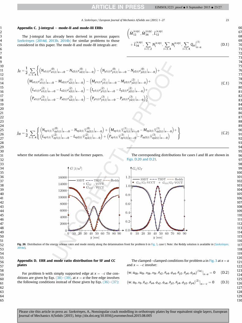
Appendix C. J-integral e mode-II and mode-III ERRs
The J-integral has already been derived in previous papersSzekr�enyes (2014d, 2013b, 2014b) for similar problems to thoseconsidered in this paper. The mode-II and mode-III integrals are:
where the notations can be found in the former papers.
Appendix D. ERR and mode ratio distribution for SF and CCplates
For problem b with simply supported edge at x ¼ �c the con-ditions are given by Eqs. (38)e(39), at x ¼ a the free edge involvesthe following conditions instead of those given by Eqs. (36)e(37):
bMðx;xyÞ12 ; bMðx;xyÞ
34 ; bLðx;xyÞ12
þ bLðx;xyÞ34 ;Xi¼1::2
Nðx;xyÞi ;
Xi¼3::4
Nðx;xyÞi ;
Xi¼1::4
Qxi
���ð1Þx¼a
(D.1)
The corresponding distributions for cases I and III are shown inFigs. D.20 and D.21.
The clampedeclamped conditions for problem a in Fig. 3 at x¼ aand x ¼ �c involve:�w;u0b;u0t ; v0b; v0t ; qx2; qx4;fx4; qy2; qy4;fy4
�ð1aÞ��x¼a ¼ 0 (D.2)
�w;u0; v0; qx2; qx4;fx2;fx4; qy2; qy4;fy2;fy4
�ð2Þ��x¼�c ¼ 0 (D.3)
JII ¼12
Xi¼1::4
(�Nx1ðiÞε
ð0Þx1ðiÞ
��x¼þ0 � Nx2ðiÞε
ð0Þx2ðiÞ
��x¼�0
���Ny1ðiÞε
ð0Þy1ðiÞ
��x¼þ0 � Ny2ðiÞε
ð0Þy2ðiÞ
��x¼�0
�þ
�Mx1ðiÞε
ð1Þx1ðiÞ
��x¼þ0 �Mx2ðiÞε
ð1Þx2ðiÞ
��x¼�0
���My1ðiÞε
ð1Þy1ðiÞ
��x¼þ0 �My2ðiÞε
ð2Þy2ðiÞ
��x¼�0
�þ�
Lx1ðiÞεð2Þx1ðiÞ
��x¼þ0 � Lx2ðiÞε
ð2Þx2ðiÞ
��x¼�0
���Ly1ðiÞε
ð2Þy1ðiÞ
��x¼þ0 � Ly2ðiÞε
ð2Þy2ðiÞ
��x¼�0
�þ�
Px1ðiÞεð3Þx1ðiÞ
��x¼þ0 � Px2ðiÞε
ð3Þx2ðiÞ
��x¼�0
���Py1ðiÞε
ð3Þy1ðiÞ
��x¼þ0 � Py2ðiÞε
ð3Þy2ðiÞ
��x¼�0
�o(C.1)
JIII ¼12
Xi¼1::4
8<:�Nxy1ðiÞbgð0Þ
xy1ðiÞ��x¼þ0 � Nxy2ðiÞbgð0Þ
xy2ðiÞ��x¼�0
�þ�Mxy1ðiÞbgð1Þ
xy1ðiÞ��x¼þ0 �Mxy2ðiÞbgð1Þ
xy2ðiÞ��x¼�0
�þ�
Lxy1ðiÞbgð2Þxy1ðiÞ
��x¼þ0 � Lxy2ðiÞbgð2Þ
xy2ðiÞ��x¼�0
�þ�Pxy1ðiÞbgð3Þ
xy1ðiÞ��x¼þ0 � Pxy2ðiÞbgð3Þ
xy2ðiÞ��x¼�0
� 9=; (C.2)
Fig. 20. Distribution of the energy release rates and mode mixity along the delamination front for problem b in Fig. 3, case I. Note: the Reddy solution is available in (Szekr�enyes,2014d).
A. Szekr�enyes / European Journal of Mechanics A/Solids xxx (2015) 1e27 23
1234567891011121314151617181920212223242526272829303132333435363738394041424344454647484950515253545556575859606162636465
66676869707172737475767778798081828384858687888990919293949596979899
100101102103104105106107108109110111112113114115116117118119120121122123124125126127128129130
EJMSOL3223_proof ■ 8 September 2015 ■ 23/27
Please cite this article in press as: Szekr�enyes, A., Nonsingular crack modelling in orthotropic plates by four equivalent single layers, EuropeanJournal of Mechanics A/Solids (2015), http://dx.doi.org/10.1016/j.euromechsol.2015.08.005
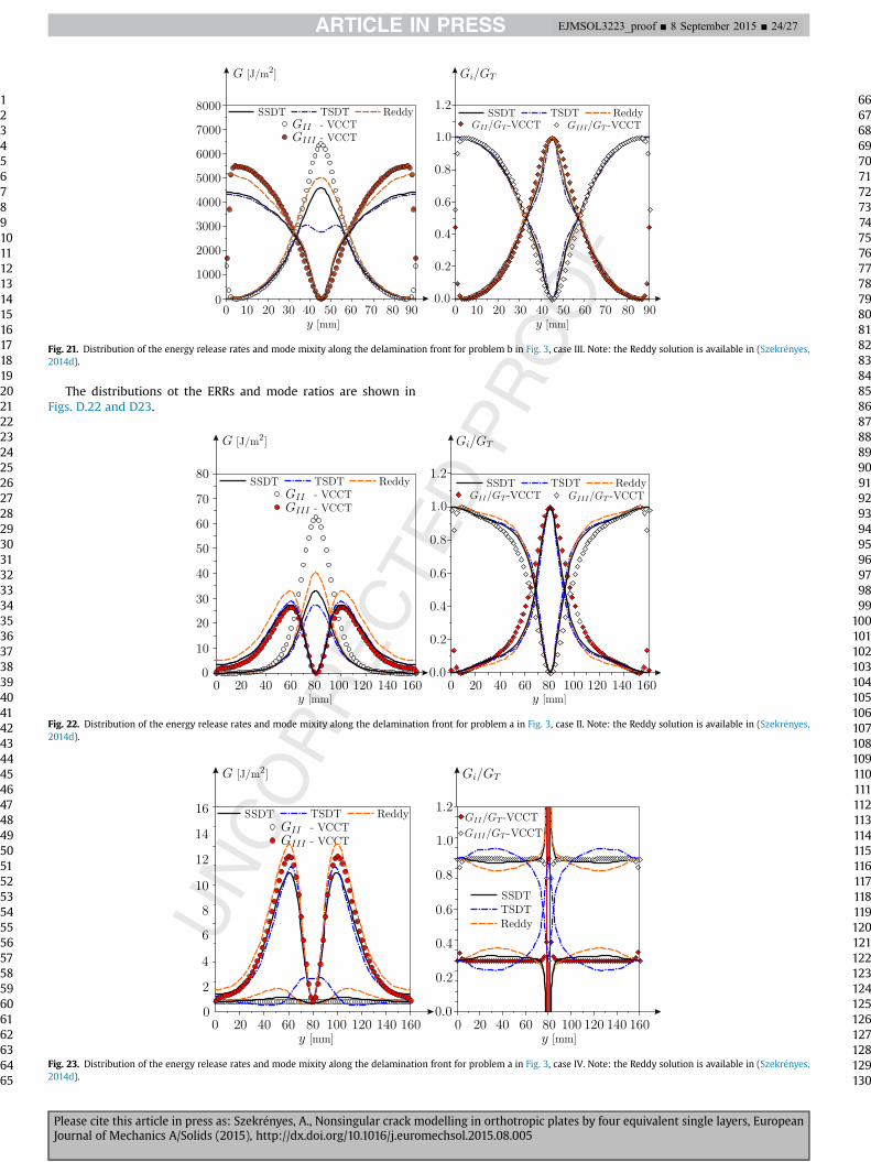
The distributions ot the ERRs and mode ratios are shown inFigs. D.22 and D23.
Fig. 23. Distribution of the energy release rates and mode mixity along the delamination front for problem a in Fig. 3, case IV. Note: the Reddy solution is available in (Szekr�enyes,2014d).
Fig. 21. Distribution of the energy release rates and mode mixity along the delamination front for problem b in Fig. 3, case III. Note: the Reddy solution is available in (Szekr�enyes,2014d).
Fig. 22. Distribution of the energy release rates and mode mixity along the delamination front for problem a in Fig. 3, case II. Note: the Reddy solution is available in (Szekr�enyes,2014d).
1234567891011121314151617181920212223242526272829303132333435363738394041424344454647484950515253545556575859606162636465
66676869707172737475767778798081828384858687888990919293949596979899
100101102103104105106107108109110111112113114115116117118119120121122123124125126127128129130
EJMSOL3223_proof ■ 8 September 2015 ■ 24/27
Please cite this article in press as: Szekr�enyes, A., Nonsingular crack modelling in orthotropic plates by four equivalent single layers, EuropeanJournal of Mechanics A/Solids (2015), http://dx.doi.org/10.1016/j.euromechsol.2015.08.005
References
Ahn, J.S., Woo, K.S., Lee, D.W., 2012. Delamination analysis of carbon fiber-reinforced peek using coarse mesh. Adv. Mater. Res. 538e541, 1624e1629.
Ahn, J.S., Kim, Y.W., Woo, K.S., 2013. Analysis of circular free edge effect in com-posite laminates by p-convergent global-local model. Int. J. Mech. Sci. 66,149e155.
Alibeigloo, A., Zanoosi, A.P., 2013. Static analysis of rectangular nano-plate usingthree-dimensional theory of elasticity. Appl. Math. Model. 37, 7016e7026.
Anderson, T.L., 2005. Fracture Mechanics e Fundamentals and Applications, thirded. CRC Press, Taylor & Francis Group, Boca Raton, London, New York,Singapore.
Aragh, B.S., Farahani, E.B., Barati, A.N., 2013. Natural frequency analysis of contin-uously graded carbon nanotube-reinforced cylindrical shells based on third-order shear deformation theory. Math. Mech. Solids 18, 264e284.
Argüelles, A., Vi~na, J., Canteli, A.F., Bonhomme, J., 2011. Influence of resin type on thedelamination behavior of carbon fiber reinforced composites under mode-IIloading. Int. J. Damage Mech. 20, 963e977.
Arrese, A., Carbajal, N., Vargas, G., Mujika, F., 2010. A new method for determiningmode II R-curve by the end-notched flexure test. Eng. Fract. Mech. 77, 51e70.
Arya, H., Shimpi, R., Naik, N., 2002. A zigzag model for laminated composite beams.Compos. Struct. 56, 21e24.
Assie, A., Kabeel, A., Mahmoud, F., 2012. Optimum design of laminated compositeplates under dynamic excitation. Appl. Math. Model. 36, 668e682.
Baddour, N. (Ed.), 2011. Recent Advances in Vibration Analysis. Intech chapter 4. pp.60e78. A Shahrjerdi and F Mustapha, Second order shear deformation theory(SSDT) for free vibration analyis on a functionally graded quadrangle plate.
Batista, M., 2012. Comparison of Reissner, Mindlin and Reddy plate models withexact three dimensional solution for simply supported isotropic and transverseinextensible rectangular plate. Meccanica 47, 257e268.
Bodaghi, M., Saidi, A.R., 2010. L�evy-type solution for buckling analysis of thickfunctionally graded rectangular plates based on the higher-order shear defor-mation plate. Appl. Math. Model. 34, 3659e3673.
Bonhomme, J., Argüelles, A., Castrillo, M.A., Vi~na, J., 2010. Computational models formode i composite fracture failure: the virtual crack closure technique versusthe two-step extension method. Meccanica 45, 297e304.
Bruno, D., Greco, F., 2001. Delamination in composite plates: influence of sheardeformability on interfacial debonding. Cem. Concr. Compos. 23, 33e45.
Bruno, D., Greco, F., Lonetti, P., 2003. A coupled interface-multilayer approach formixed mode delamination and contact analysis in laminated composites. Int. J.Solids Struct. 40, 7245e7268.
Bruno, D., Greco, F., Lonetti, P., 2005. A 3D delamination modelling technique basedon plate and interface theories for laminated structures. Eur. J. Mech. A/Solids24, 127e149.
Burlayenko, V.N., Sadowski, T., 2012. A numerical study of the dynamic response ofsandwich plates initially damaged by low-velocity impact. Comput. Mater. Sci.52, 212e216.
Chang, H.H., Tarn, J.Q., 2012. Three-dimensional elasticity solutions for rectangularorthotropic plates. J. Elast. 108, 49e66.
Chaudhuri, R.A., Balaraman, K., 2007. A novel method for fabrication of fiber rein-forced plastic laminated plates. Compos. Struct. 77, 160e170.
Cherepanov, G.P., 1997. Methods of Fracture Mechanics: Solid Matter Physics.Kluwer Academic Publishers, Dordrecht, Boston, London.
Chirica, I., 2013. Torsion dynamic behaviour of the ship hull made out of layeredcomposites. Math. Probl. Eng. 1e7. Article ID 793412.
Chirica, I., Musat, S.D., Chirica, R., Beznea, E.F., 2011. Torsional behaviour of the shiphull composite model. Comput. Mater. Sci. 50, 1381e1386.
Chou, P.C., Pagano, N.J., 1967. Elasticity e Tensor, Dyadic, and Engineering Ap-proaches. D. Van Nostrand Company, Inc., Princeton, New Jersey, Toronto,London.
Christoforou, A.P., Elsharkawy, A.A., Guedoua, L.H., 2008. An inverse solution forlow-velocity impact in composite plates. Comput. Struct. 86, 988e996.
Czig�any, T., De�ak, T., 2012. Preparation and manufacturing techniques for macro-and microcomposites. Polym. Compos. 1, 111e134.
Davidson, B.D., Sediles, F.O., 2011. Mixed-mode I-II-III delamination toughnessdetermination via a shear-torsion-bending test. Compos. A Appl. Sci. Manuf. 42,589e603.
Davidson, B.D., Yu, L., Hu, H., 2000. Determination of energy release rate and modemix in three-dimensional layered structures using plate theory. Int. J. Fract. 105,81e104.
Davidson, B., Bansal, A., Bing, Q., Sun, X., 2009. Geometrically nonlinear determi-nation of energy release rate and mode ratio in single leg bending tests. J. Reinf.Plast. Compos. 28, 1881e1901.
de Baere, I., Jacques, S., Van Paepegem, W., Degrieck, J., 2012. Study of the mode Iand mode II interlaminar behaviour of a carbon fabric reinforced thermoplastic.Polym. Test. 31, 322e332.
Eftekhari, S., Jafari, A., 2012. A mixed method for free and forced vibration ofrectangular plates. Appl. Math. Model. 36, 2814e2831.
Endo, M., 2015. Study on an alternative deformation concept for the Timoshenkobeam and Mindlin plate models. Int. J. Eng. Sci. 87, 32e46.
Endo, M., Kimura, N., 2007. An alternative formulation of the boundary valueproblem for the Timoshenko beam and Mindlin plate. J. Sound Vib. 301,355e373.
Fern�andez, M.V., Moura, M.F.S.F., da Silva, A.T., Marques, L.F.M., 2013. Mixed-modefatigue/fracture characterization of composite bonded joints using the single-leg bending test. Compos. A Appl. Sci. Manuf. 44, 63e69.
Ferreira, A.J.M., Roque, C.M.C., Carrera, E., Cinefra, M., Polit, O., 2011. Two higherorder zig-zag theories for the accurate analysis of bending, vibration andbuckling response of laminated plates by radial basis functions collocation anda unified formulation. J. Compos. Mater. 45, 2523e2536.
Ganapathy, S., Rao, K., 1998. Failure analysis of laminated composite cylindrical/spherical shell panels subjected to low-velocity impact. Comput. Struct. 68,627e641.
Gheshlaghi, R., Hojjati, M., Daniali, H., 2006. Analysis of composite pressure vessels.In: Gdoutos, E. (Ed.), Fracture of Nano and Engineering Materials and Structures.Springer Netherlands, pp. 335e336.
Goch, G., Knapp, W., H€artig, F., 2012. Precision engineering for wind energy systems.CIRP Annal. Manuf. Technol. 61, 611e634.
Goodmiller, G., TerMaath, S., 2014. Investigation of composite patch performanceunder low-velocity impact loading. In: 55th AIAA/ASME/ASCE/AHS/SC Struc-tures, Structural Dynamics, and Materials Conference. National Harbor, Mary-land, USA.
Gracia, J.D., Boyano, A., Arrese, A., Mujika, F., 2015. A new approach for determiningthe R-curve in DCB tests without optical measurements. Eng. Fract. Mech. 135,274e285.
Hajheidari, H., Mirdamadi, H.R., 2013. Frequency-dependent vibration analysis ofsymmetric cross-ply laminated plate of levy-type by spectral element and finitestrip procedures. Appl. Math. Model. 37, 7193e7205.
Hajikazemi, M., Sadr, M., 2014a. Stiffness reduction of cracked general symmetriclaminates using a variational approach. Int. J. Solids Struct. 51, 1483e1493.
Hajikazemi, M., Sadr, M., 2014b. A variational model for stress analysis in crackedlaminates with arbitrary symmetric lay-up under general in-plane loading. Int.J. Solids Struct. 51, 516e529.
Hosseini-Hashemi, S., Fadaee, M., Taher, H.R.D., 2011. Exact solutions for free flex-ural vibration of L�evy-type rectangular thick plates via third-order sheardeformation. Appl. Math. Model. 35, 708e727.
Islam, M.M., Kapania, R.K., 2014. Global-local finite element analysis of adhesivejoints and crack propagation. J. Aircr. 51, 310e319.
Ivan�cevi�c, D., Smojver, I., 2011. Hybrid approach in bird strike damage prediction onaeronautical composite structures. Compos. Struct. 94, 15e23.
Izadi, M., Tahani, M., 2010. Analysis of interlaminar stresses in general cross-plylaminates with distributed piezoelectric actuators. Compos. Struct. 757e768.
Jiang, G., 2014. Impact of new composite material technology on the performance ofthe tennis rackets. Appl. Mech. Mater. 484e485, 114e117. Cited By 0.
Jianqiao, Y., 2003. Laminated Composite Plates and Shells e 3D Modelling. Springer,London, Berlin, Heidelberg, New York, Hong Kong, Milan, Paris, Tokyo.
Johnston, A., Davidson, B., 2014. Intrinsic coupling of near-tip matrix crack forma-tion to mode III delamination advance in laminated polymeric matrix com-posites. Int. J. Solids Struct. 51, 2360e2369.
Johnston, A., Davidson, B., Simon, K., 2014. Assessment of split-beam-type tests formode III delamination toughness determination. Int. J. Fract. 185, 31e48.
Jumel, J., Budzik, M.K., Shanahan, M.E.R., 2011a. Beam on elastic foundation withanticlastic curvature: application to analysis of mode I fracture tests. Eng. Fract.Mech. 78, 3253e3269.
Jumel, J., Budzik, M.K., Shanahan, M.E.R., 2011b. Process zone in the single cantileverbeam under transverse loading. part I: theoretical analysis. Theor. Appl. Fract.Mech. 56, 7e12.
Kapuria, S., Kumari, P., 2012. Boundary layer effects in levy-type rectangularpiezoelectric composite plates using a coupled efficient layerwise theory. Eur. J.Mech. A/Solids 36, 122e140.
Kenane, M., Benmedakhene, S., Azari, Z., 2010. Fracture and fatigue study of uni-directional glass/epoxy laminate under different mode of loading. Fatigue Fract.Eng. Mater. Struct. 33, 285e293.
Khan, L., Mahmood, A., Hassan, B., Sharif, T., Khushnod, S., Khan, Z., 2014. Cost-effective manufacturing process for the development of automotive from en-ergy efficient composite materials and sandwich structures. Polym. Compos. 35,97e104. Cited By 0.
Khoshravan, M.R., Moslemi, M., 2014. Investigation on mode III interlaminar frac-ture of glass/epoxy laminates using a modified split cantilever beam test. Eng.Fract. Mech. (available online). Q4
Kim, S., Kim, J.S., Yoon, H., 2011. Experimental and numerical investigations of modeI delamination behaviors of woven fabric composites with carbon, kevlar andtheir hybrid fibers. Int. J. Precis. Eng. Manuf. 12, 321e329.
Koll�ar, L.P., Springer, G.S., 2003. Mechanics of Composite Structures. CambridgeUniversity Press, Cambridge, New York, Melbourne, Madrid, Cape Town,Singapore, S~ao Paolo.
Kondo, A., Sato, Y., Suemasu, H., Gouzu, K., Aoki, Y., 2010. Characterization of frac-ture resistance of carbon/epoxy composite laminates during mixed-mode II andIII stable damage propagation. J. Jpn. Soc. Compos. Mater. 36, 179e188.
Kondo, A., Sato, Y., Suemasu, H., Aoki, Y., 2011. Fracture resistance of carbon/epoxycomposite laminates under mixed-mode II and III failure and its dependence onfracture morphology. Adv. Compos. Mater. 20, 405e418.
Kotousov, A., Berto, F., Lazzarin, P., Pegorin, F., 2012. Three dimensional finiteelement mixed fracture mode under anti-plane loading of a crack. Theor. Appl.Fract. Mech. 62, 26e33.
Kotousov, A., Lazzarin, P., Berto, F., Pook, L., 2013. Three-dimensional stress states atcrack tip induced by shear and anti-plane loading. Eng. Fract. Mech. 108, 65e74.
A. Szekr�enyes / European Journal of Mechanics A/Solids xxx (2015) 1e27 25
1234567891011121314151617181920212223242526272829303132333435363738394041424344454647484950515253545556575859606162636465
66676869707172737475767778798081828384858687888990919293949596979899
100101102103104105106107108109110111112113114115116117118119120121122123124125126127128129130
EJMSOL3223_proof ■ 8 September 2015 ■ 25/27
Please cite this article in press as: Szekr�enyes, A., Nonsingular crack modelling in orthotropic plates by four equivalent single layers, EuropeanJournal of Mechanics A/Solids (2015), http://dx.doi.org/10.1016/j.euromechsol.2015.08.005
Kreja, I., Schmidt, R., 2006. Large rotations in first-order shear deformation FEanalysis of laminated shells. Int. J. Non-Linear Mech. 41, 101e123.
Langdon, G., Cantwel, W., Guan, Z., Nurick, G., 2014. The response of polymericcomposite structures to air-blast loading: a state-of-the-art. Int. Mater. Rev. 59,159e177. Cited By 0.
Lerpiniere, A., Caron, J.F., Diaz, A.D., Sab, K., 2014. The LS1 model for delaminationpropagation in multilayered materials at interfaces: a comparison betweenexperimental and finite elements strain energy release rates. Int. J. Solids Struct.51, 3973e3986.
Li, L., Jing, H., 2014. Research on the application of fiber-reinforced compositematerials on sports equipments. Appl. Mech. Mater. 687e691, 4244e4247. CitedBy 0.
Liu, P., Yang, J., Wang, B., Zhou, Z., Zheng, J., 2015. A study on the intralaminardamage and interlaminar delamination of carbon fiber composite laminatesunder three-point bending using acoustic emission. J. Fail. Anal. Prev. 15,101e121.
L�opez-Men�endez, A., Vi�na, J., Argüelles, A., Bonhomme, J., Moll�on, V., Lozano, M.,2014. A new methodology for testing composite materials in mode III of frac-ture. In: 16th European Conference on Composite Materials, ECCM 2014, June22e26, Sevilla, Spain.
Lu, G., Zhao, B., Wu, X., 2013. Refined theory and decomposed theorem oftransversely isotropic thermoporoelastic beam. Compt. Rend. M�ec. 341,701e708.
Marat-Mendes, R.M., Freitas, M.M., 2009. Characterisation of the edge crack torsion(ECT) test for the measurement of the mode III interlaminar fracture toughness.Eng. Fract. Mech. 76, 2799e2809.
Marat-Mendes, R.M., Freitas, M.M., 2010. Failure criteria for mixed mode delami-nation in glass fibre epoxy composites. Compos. Struct. 92, 2292e2298.
Mehrabadi, F.A., 2013. Analysis of pure mode III and mixed mode (IIIþ II) inter-laminar crack growth in polymeric woven fabrics. Mater. Des. 44, 429e437.
Mehrabadi, F.A., 2014. The use of ECT and 6PBP tests to evaluate fracture behavior ofadhesively bonded steel/epoxy joints under mode-III and mixed mode III/II.Appl. Adhes. Sci. 2, 1e15.
Mehrabadi, F.A., Khosravan, M., 2013. Mode III interlaminar fracture in woven glass/epoxy composite laminates. World Acad. Sci. Eng. Technol. 73, 479e483.
M�esz�aros, L., De�ak, T., Balogh, G., Czvikovszky, T., Czig�any, T., 2013. Preparation andmechanical properties of injection moulded polyamide 6 matrix hybrid nano-composite. Compos. Sci. Technol. 75, 22e27.
Miura, M., Shindo, Y., Takeda, T., Narita, F., 2012. Interlaminar fracture character-ization of woven glass/epoxy composites under mixed-mode II/III loadingconditions at cryogenic temperatures. Eng. Fract. Mech. 96, 615e625.
Miura, M., Shindo, Y., Takeda, T., Narita, F., 2014. Mixed-mode I/III fatigue delami-nation growth in woven glass/epoxy composite laminates at cryogenic tem-peratures. J. Compos. Mater. 48, 1251e1259.
Mladensky, A.S., Rizov, V., 2013. Analysis of mixed mode II/III crack in bilayeredcomposite beam. J. Theor. Appl. Mech. 42, 41e52.
Nanda, N., Sahu, S.K., 2012. Free vibration analysis of delaminated composite shellsusing different shell theories. Int. J. Press. Vessel. Pip. 98, 111e118.
Nikbakht, M., Choupani, N., 2008. Fracture toughness characterization of carbon-epoxy composite using arcan specimen. World Acad. Sci. Eng. Technol. 41,738e744.
Nikbakht, M., Choupani, N., Hosseini, S.R., 2010. 2D and 3D interlaminar fractureassessment under mixed-mode loading conditions. Mater. Sci. Eng. A 516,162e168.
Norhidayah, M., Hambali, A., Yuhazri, Y., Zolkarnain, M., Taufik, H.Y., Saifuddin, H.,2014. A review of current development in natural fiber composites in auto-motive applications. Appl. Mech. Mater. 564, 3e7.
Oktem, A.S., Alankaya, V., Soares, C.G., 2013. Boundary-discontinuous Fourieranalysis of simply supported cross-ply plates. Appl. Math. Model. 37,1378e1389.
Ovesy, H., Totounferoush, A., Ghannadpour, S., 2015. Dynamic buckling analysis ofdelaminated composite plates using semi-analytical finite strip method.J. Sound Vib. 343, 131e143.
Panda, S.K., Singh, B.N., 2009. Nonlinear free vibration of spherical shell panel usinghigher order shear deformation theory e a finite element approach. Int. J. Press.Vessel. Pip. 86, 373e383.
Panda, S.K., Singh, B.N., 2011. Large amplitude free vibration analysis of thermallypost-buckled composite doubly curved panel using nonlinear FEM. Finite Elem.Anal. Des. 47, 378e386.
Peng, L., Zhang, J., Zhao, L., Bao, R., Yang, H., Fei, B., 2011. Mode I delaminationgrowth of multidirectional composite laminates under fatigue loading.J. Compos. Mater. 45, 1077e1090.
Peng, L., Xu, J., Zhang, J., Zhao, L., 2012. Mixed mode delamination growth ofmultidirectional composite laminates under fatigue loading. Eng. Fract. Mech.96, 676e686.
Pereira, F., de Moura, M., Dourado, N., Morais, J., Dias, M., 2014. Bone fracturecharacterization under mixed-mode IþII loading using the single leg bendingtest. Biomech. Model. Mechanobiol. 13, 1331e1339.
Petrolito, J., 2014. Vibration and stability analysis of thick orthotropic plates usinghybrid-Trefftz elements. Appl. Math. Model. (Available online).
Petrova, V.E., Sadowski, T., 2012. Theoretical analysis of mode II cracks in a compactshear specimen. Comput. Mater. Sci. 64, 248e252.
Petrova, V.E., Marsavina, L., Sadowski, T., 2012. Revisit of compact mode II crackspecimen: analysis and fracture interpretation. Theor. Appl. Fract. Mech. 59,41e48.
Plain, K.P., Tong, L., 2011. An experimental study on mode I and II fracture toughnessof laminates stitched with a one-sided stitching technique. Compos. A Appl. Sci.Manuf. 42, 203e210.
Radosavljevi�c, V., Dra�zi�c, M., 2010. Exact solution for buckling of FCFC steppedrectangular plates. Appl. Math. Model. 34, 3841e3849.
Raju, I., jr Crews, J., Aminpour, M., 1988. Convergence of strain energy release ratecomponents for edge-delaminated composite laminates. Eng. Fract. Mech. 30,383e396.
Reddy, J.N., 2004. Mechanics of Laminated Composite Plates and Shells e Theoryand Analysis. CRC Press, Boca Raton, London, New York, Washington D.C.
Rice, J.R., 1968. A path independent integral and the approximate analysis of strainconcentration by notches and cracks. J. Appl. Mech. 35, 379e386.
Rizov, V.I., 2012a. Fracture in composites e an overview (Part I). J. Theor. Appl.Mech. 42, 3e42. Sofia.
Rizov, V.I., 2012b. Fracture in composites e an overview (Part II). J. Theor. Appl.Mech. 42, 23e32. Sofia.
Rizov, V., Mladensky, A.S., 2012. Analysis of mode II crack in bilayered compositebeam. J. Theor. Appl. Mech. 42, 67e78.
Rizov, V., Shipsha, A., Zenkert, D., 2005. Indentation study of foam core sandwichcomposite panels. Compos. Struct. 69, 95e102.
Rizov, V., Shindo, Y., Horiguchi, K., Narita, F., 2006. Mode III interlaminar fracturebehaviour of glass fiber reinforced polymer woven laminates at 293 to 4 k. Appl.Compos. Mater. 13, 287e304.
Rodríguez-Gonz�alez, J., May-Pat, A., Avil�es, F., 2014. A beam specimen to measurethe face/core fracture toughness of sandwich materials under a tearing loadingmode. Int. J. Mech. Sci. 79, 84e94.
Sabik, A., Kreja, I., 2013. Large thermo-elastic displacement and stability FEManalysis of multilayered plates and shells. Thin-Wall. Struct. 71, 119e133.
Saeedi, N., Sab, K., Caron, J.F., 2012a. Delaminated multilayered plates under uniaxialextension. part I: analytical analysis using a layerwise stress approach. Int. J.Solids Struct. 49, 3711e3726.
Saeedi, N., Sab, K., Caron, J.F., 2012b. Delaminated multilayered plates under uni-axial extension. part II: efficient layerwise mesh strategy for the prediction ofdelamination onset. Int. J. Solids Struct. 49, 3727e3740.
Saeedi, N., Sab, K., Caron, J.F., 2013a. Cylindrical bending of multilayered plates withmulti-delamination via a layerwise stress approach. Compos. Struct. 95,728e739.
Saeedi, N., Sab, K., Caron, J.F., 2013b. Stress analysis of long multilayered platessubjected to invariant loading: analytical solutions by a layerwise stress model.Compos. Struct. 100, 307e322.
Sahoo, R., Singh, B., 2013a. A new inverse hyperbolic zigzag theory for the staticanalysis of laminated composite and sandwich plates. Compos. Struct. 105,385e397.
Sahoo, R., Singh, B., 2013b. A new shear deformation theory for the static analysis oflaminated composite and sandwich plates. Int. J. Mech. Sci. 75, 324e336.
Sahoo, R., Singh, B., 2014a. A new trigonometric zigzag theory for buckling and freevibration analysis of laminated composite and sandwich plates. Compos. Struct.117, 316e332.
Sahoo, R., Singh, B., 2014b. A new trigonometric zigzag theory for static analysis oflaminated composite and sandwich plates. Aerosp. Sci. Technol. 35, 15e28.
Salem, N.B., Budzik, M.K., Jumel, J., Shanahan, M.E.R., Lavelle, F., 2013. Investigationof the crack front process zone in the double cantilever beam test with backfacestrain monitoring technique. Eng. Fract. Mech. 98, 272e283.
Sarvestani, H.Y., Sarvestani, M.Y., 2012. Free-edge stress analysis of general com-posite laminates under extension, torsion and bending. Appl. Math. Model. 36,1570e1588.
Shahrjerdi, A., Bayat, M., Mustapha, F., Sapuan, S.M., Zahari, R., 2010. Second-ordershear deformation theory to analyze stress distribution for solar functionallygraded plates. Mech. Based Des. Struct. Mach. 38, 348e361.
Shahrjerdi, A., Mustapha, F., Bayat, M., Majid, D.L.A., 2011. Free vibration analysis ofsolar functionally graded plates with temperature-dependent material prop-erties using second order shear deformation theory. J. Mech. Sci. Technol. 25,1e15.
Shi, G., 2007. A new simple third-order shear deformation theory of plates. Int. J.Solids Struct. 44, 4399e4417.
Shimpi, R., Patel, H., 2006. A two variable refined plate theory for orthotropic plateanalysis. Int. J. Solids Struct. 43, 6783e6799.
Singh, V.K., Panda, S.K., 2014. Nonlinear free vibration analysis of single/doublycurved composite shallow shell panels. Thin-Wall. Struct. 85, 341e349.
Smojver, I., Ivan�cevi�c, D., 2010. Numerical simulation of bird strike damage pre-diction in airplane flap structure. Compos. Struct. 92, 2016e2026.
Smojver, I., Ivan�cevi�c, D., 2011. Bird strike damage analysis in aircraft structuresusing abaqus/explicit and coupled. Compos. Sci. Technol. 71, 489e498.
Smojver, I., Ivan�cevi�c, D., 2012. Advanced modelling of bird strike on high lift de-vices using hybrid. Aerosp. Sci. Technol. 23, 224e232.
Steigmann, D.J., 2012. Refined theory for linearly elastic plates: laminae and lami-nates. Math. Mech. Solids 17, 351e363.
Su, D., 2014. Application of fiber reinforced composites for sports instruments. Appl.Mech. Mater. 687e691, 4256e4259. Cited By 0.
Suemasu, H., Kondo, A., Gozu, K., Aoki, Y., 2010. Novel test method for mixed modeII and III interlaminar fracture toughness. Adv. Compos. Mater. 19, 349e361.
Szekr�enyes, A., 2007. Delamination fracture analysis in the GІ І-GІ ІІ plane usingprestressed composite beams. Int. J. Solids Struct. 44, 3359e3378.
Szekr�enyes, A., 2009a. Improved analysis of the modified split-cantilever beam formode III fracture. Int. J. Mech. Sci. 51, 682e693.
A. Szekr�enyes / European Journal of Mechanics A/Solids xxx (2015) 1e2726
1234567891011121314151617181920212223242526272829303132333435363738394041424344454647484950515253545556575859606162636465
66676869707172737475767778798081828384858687888990919293949596979899
100101102103104105106107108109110111112113114115116117118119120121122123124125126127128129130
EJMSOL3223_proof ■ 8 September 2015 ■ 26/27
Please cite this article in press as: Szekr�enyes, A., Nonsingular crack modelling in orthotropic plates by four equivalent single layers, EuropeanJournal of Mechanics A/Solids (2015), http://dx.doi.org/10.1016/j.euromechsol.2015.08.005
Szekr�enyes, A., 2009b. Interlaminar fracture analysis in the GІ-GІ ІІ plane usingprestressed transparent composite beams. Compos. A Appl. Sci. Manuf. 40,1621e1631.
Szekr�enyes, A., 2011a. The influence of crack length and delamination width on themode-III energy release rate of laminated composites. J. Compos. Mater. 45,279e294.
Szekr�enyes, A., 2011b. Interlaminar fracture analysis in the GІ-GІІ-GІІ І space usingprestressed transparent composite beams. J. Reinf. Plast. Compos. 30,1655e1669.
Szekr�enyes, A., 2012. Interlaminar fracture analysis in the GІІ-GІІ І plane usingprestressed transparent composite beams. Compos. A Appl. Sci. Manuf. 43,95e103.
Szekr�enyes, A., 2013a. Interface fracture in orthotropic composite plates usingsecond-order shear deformation theory. Int. J. Damage Mech. 22,1161e1185.
Szekr�enyes, A., 2013b. The system of exact kinematic conditions and application todelaminated first-order shear deformable composite plates. Int. J. Mech. Sci. 77,17e29.
Szekr�enyes, A., 2014a. Analysis of classical and first-order shear deformable crackedorthotropic plates. J. Compos. Mater. 48, 1441e1457.
Szekr�enyes, A., 2014b. Antiplane-inplane shear mode delamination between twosecond-order shear deformable composite plates. Math. Mech. Solids. http://dx.doi.org/10.1177/1081286515581871.
Szekr�enyes, A., 2014c. Application of Reddy's third-order theory to delaminatedorthotropic composite plates. Eur. J. Mech. A/Solids 43, 9e24.
Szekr�enyes, A., 2014d. Bending solution of third-order orthotropic Reddy plateswith asymmetric interfacial crack. Int. J. Solids Struct. 51, 2598e2619.
Szekr�enyes, A., 2014e. Stress and fracture analysis in delaminated orthotropiccomposite plates using third-order shear deformation theory. Appl. Math.Model. 38, 3897e3916.
Taj, M.G., Chakrabarti, A., Sheikh, A.H., 2013. Analysis of functionally graded platesusing higher order shear. Appl. Math. Model. 37, 8484e8494.
Takeda, T., Miura, M., Shindo, Y., Narita, F., 2013. Fatigue delamination growth inwoven glass/epoxy composite laminates under mixed-mode II/III loading con-ditions at cryogenic temperatures. Cryogenics 58, 55e61.
Talha, M., Singh, B., 2010. Static response and free vibration analysis of FGM platesusing higher order shear deformation theory. Appl. Math. Model. 34,3991e4011.
Tang, D., 2014. The application of carbon fiber materials in sports equipment. Appl.Mech. Mater. 443, 613e616.
Thai, H.T., Choi, D.H., 2013. Analytical solutions of refined plate theory for bending,buckling and vibration analyses of thick plates. Appl. Math. Model. 37,8310e8323.
Thai, H.T., Kim, S.E., 2012. L�evy-type solution for free vibration analysis of ortho-tropic plates based on two variable refined plate theory. Appl. Math. Model. 36,3870e3882.
Thai, H.T., Vo, T.P., 2013. A new sinusoidal shear deformation theory for bending,buckling, and vibration of functionally graded plates. Appl. Math. Model. 37,3269e3281.
Thai, C.H., Tran, L.V., Tran, D.T., Nguyen-Thoi, T., Nguyen-Xuan, H., 2012. Analysis oflaminated composite plates using higher-order shear deformation plate theoryand node-based smoothed discrete shear gap method. Appl. Math. Model. 36,5657e5677.
Valvo, P.S., 2012. A revised virtual crack closure technique for physically consistentfracture mode partitioning. Int. J. Fract. 173, 1e20.
Wang, C., Zhang, H., Shi, G., 2012. 3-D finite element simulation of impact damage oflaminated plates using solid-shell interface elements. Appl. Mech. Mater.130e132, 766e770.
Wennberg, D., Stichel, S., 2014. Multi-functional design of a composite high-speedtrain body structure. Struct. Multidiscip. Optim. 50, 475e488.
Xiang, S., Kang, G.W., Xing, B., 2012. A nth-order shear deformation theory for thefree vibration analysis on the isotropic plates. Meccanica 47, 1913e1921.
Yang, B., Ding, H.J., Chen, W.Q., 2012. Elasticity solutions for functionally gradedrectangular plates with two opposite edges simply supported. Appl. Math.Model. 36, 488e503.
Yoshihara, H., 2006. Examination of the 4-ENF test for measuring the mode III R-curve of wood. Eng. Fract. Mech. 73, 42e63.
Yoshihara, H., Satoh, A., 2009. Shear and crack tip deformation correction for thedouble cantilever beam and three-point end-notched flexure specimens formode I and mode II fracture toughness measurement of wood. Eng. Fract. Mech.76, 335e346.
Zammit, A.D., Feih, S., Orifici, A.C., 2011. 2D numerical investigation of pre-tensionon low velocity impact damage of sandwich structures, 21e26 Aug. In: 18thInternational Conference on Composite Materials (ICCM18). Jeju InternationalConvention Center, Jeju Island, SOUTH KOREA, pp. 1e6.
Zhang, L., 2014. Application of new materials in the field of sports apparel. Adv.Mater. Res. 978, 31e35.
Zhang, J., Fox, B.L., 2007. Manufacturing influence on the delamination fracturebehavior of the T800H/3900-2 carbon fiber reinforced polymer composites.Mater. Manuf. Process. 22, 768e772.
Zhao, B., Wu, D., Wang, M., 2013. The refined theory and the decomposed theoremof a transversely isotropic elastic plate. Eur. J. Mech. A/Solids 39, 243e250.
Zhou, W., Liang, X., Li, Y., You, S., Liu, R., Chai, H., Lv, Z., 2013. Acoustic emissionmonitoring for delaminated composites under bending damage failure condi-tion. Appl. Mech. Mater. 310, 51e54.
A. Szekr�enyes / European Journal of Mechanics A/Solids xxx (2015) 1e27 27
1234567891011121314151617181920212223242526272829303132333435
3637383940414243444546474849505152535455565758596061626364656667686970
EJMSOL3223_proof ■ 8 September 2015 ■ 27/27
Please cite this article in press as: Szekr�enyes, A., Nonsingular crack modelling in orthotropic plates by four equivalent single layers, EuropeanJournal of Mechanics A/Solids (2015), http://dx.doi.org/10.1016/j.euromechsol.2015.08.005