Embed Size (px)
Citation preview
1
GENESIS-VP™: User’s Manual
Decatur Electronics, Inc.
GENESIS-VP™User’s Manual
715 Bright StreetDecatur, IL 62522
USA/Canada: 1.800.428.4315FAX: 1.217.428.5302INTL: 1.217.428.4315www.decaturradar.com
Revised December 28, 1999
GENESIS-VP™: User’s Manual
2
INSERT
Genesis-VP
Instructions for use of the target direction tracking mode.
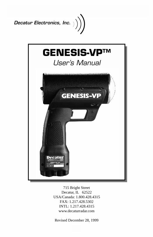
Your Genesis-VP speed radar pistol may have had target direction trackingmode added to its program software during product configuration. Thefollowing explanations and instructions apply to target direction trackingmode with the Genesis-VP.
You can determine whether or not target direction tracking mode is on or offby going into the secondary menu and toggling to the “dir” window. If itsays “on” then, of course, target direction tracking mode is on. If it says“off” then, of course, it is off and the unit will function as a standardGenesis-VP.
When operating the Genesis-VP in target direction tracking mode:
1. The Genesis-VP will lock onto the target that has the strongest returnsignal and also attempt to determine that target’s direction of travel.The target’s speed will be displayed in the left window and, ifsuccessful in determining target direction, the target direction will bedisplayed in the right window. A “t” for “towards” will be displayed fora target moving toward the Genesis-VP and an “A” for “away” will bedisplayed for a target moving away from the Genesis-VP. If theGenesis-VP is not successful in determining the target’s direction oftravel then neither a “t” or an “A” will be displayed.
2. When you lock a target the locked target speed will be displayed in theright window. The right display will alternately flash this locked speedand the direction of the locked target (if the direction was determined).
3. If you use the faster target mode in conjunction with the target directiontracking mode then this rule of thumb applies… When the right windowis not being used by another function then a “t” for “toward” or an “A”for “away” will be displayed in the right window to indicate the target’sdirection of travel.
3
GENESIS-VP™: User’s Manual
Table of Contents
1. Quick Start Instructions ........................................... 4
2. Controls ..................................................................... 9
3. Displays ................................................................... 14
4. Modes of Operation ................................................ 16
5. Serial Communications Option ............................. 18
6. Field Tests ................................................................ 18
7. Care, Cleaning, and Storage .................................. 21
8. Limitations to Doppler RADAR .............................. 21
9. Warranty .................................................................. 25
10. Service Return Procedure ...................................... 26
Appendix 1, Specifications .............................................. 27
Appendix 2, FDA Notice ................................................... 28
Appendix 3, FCC/ISC Documents ................................... 30
Appendix 4, Case Law ...................................................... 31
Copyright © 1998, Decatur Electronics, Inc.
GENESIS-VP™: User’s Manual
4
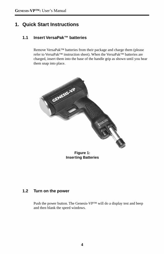
Figure 1:Inserting Batteries
1. Quick Start Instructions
1.1 Insert VersaPak™ batteries
Remove VersaPak™ batteries from their package and charge them (pleaserefer to VersaPak™ instruction sheet). When the VersaPak™ batteries arecharged, insert them into the base of the handle grip as shown until you hearthem snap into place.
1.2 Turn on the power
Push the power button. The Genesis-VP™ will do a display test and beepand then blank the speed windows.
5
GENESIS-VP™: User’s Manual
1.3 Set Menu Options
Primary menu
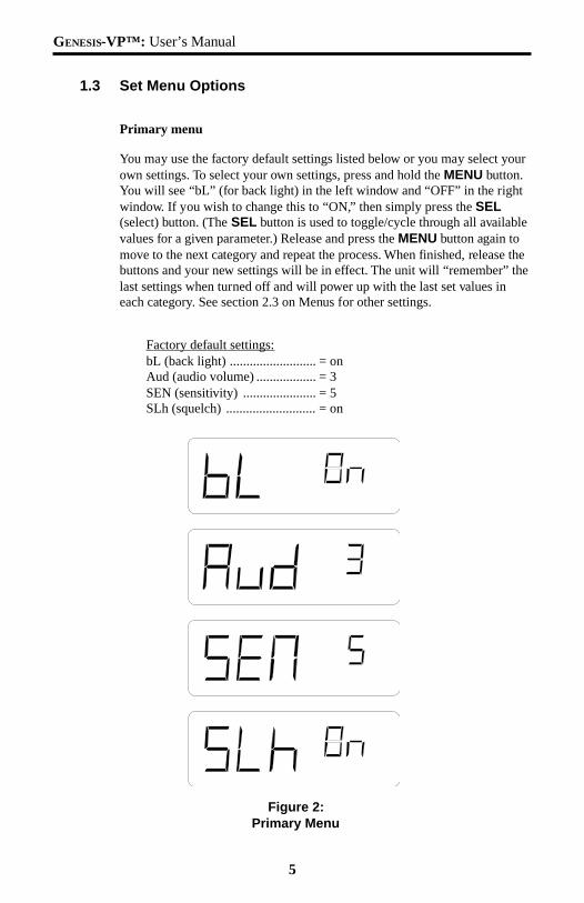
You may use the factory default settings listed below or you may select yourown settings. To select your own settings, press and hold the MENU button.You will see “bL” (for back light) in the left window and “OFF” in the rightwindow. If you wish to change this to “ON,” then simply press the SEL(select) button. (The SEL button is used to toggle/cycle through all availablevalues for a given parameter.) Release and press the MENU button again tomove to the next category and repeat the process. When finished, release thebuttons and your new settings will be in effect. The unit will “remember” thelast settings when turned off and will power up with the last set values ineach category. See section 2.3 on Menus for other settings.
Factory default settings:bL (back light) .......................... = onAud (audio volume) .................. = 3SEN (sensitivity) ...................... = 5SLh (squelch) ........................... = on
Figure 2:Primary Menu
GENESIS-VP™: User’s Manual
6
Secondary menu
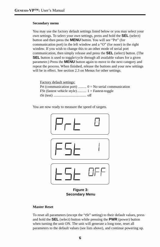
You may use the factory default settings listed below or you may select yourown settings. To select your own settings, press and hold the SEL (select)button and then press the MENU button. You will see “Prt” (forcommunication port) in the left window and a “O” (for none) in the rightwindow. If you wish to change this to an other mode of serial portcommunication, then simply release and press the SEL (select) button. (TheSEL button is used to toggle/cycle through all available values for a givenparameter.) Press the MENU button again to move to the next category andrepeat the process. When finished, release the buttons and your new settingswill be in effect. See section 2.3 on Menus for other settings.
Factory default settings:Prt (communication port) ......... 0 = No serial communicationFSt (fastest vehicle style) .......... 1 = Fastest-toggletSt (test) .................................... off
You are now ready to measure the speed of targets.
Figure 3:Secondary Menu
Master Reset
To reset all parameters (except the “tSt” setting) to their default values, pressand hold the SEL (select) button while pressing the PWR (power) buttonwhen turning the unit ON. The unit will generate a long tone, reset allparameters to the default values (see lists above), and continue powering up.
7
GENESIS-VP™: User’s Manual
1.4 Measuring the speed of a target
Measuring the speed of a target in strongest signal mode.
Point the Genesis-VP™ at a moving vehicle; pull and hold the trigger. Whilethe trigger is being held, the Genesis-VP™ is transmitting a signal andmeasuring speeds. You should see a speed in the left window. This is thespeed of the vehicle returning the strongest signal. To lock the speed, simplyrelease the trigger and pull (and hold) it again quickly (within a half of asecond) and the current speed will be locked in the right window while theleft window continues to track the vehicle’s speed. To clear the locked speed,either lock another speed in the same manner or release the trigger for morethan half a second and pull the trigger again.
Measuring the speed of a target in fastest vehicle mode.
The Genesis-VP™ can operate in one of two “fastest vehicle” modes,selected in the secondary menu, fast-hold and fast-toggle. See section 2.3 onMenus for changing to the other fastest vehicle mode.
Fast-hold style.
Point the Genesis-VP™ at two or more moving vehicles; pull and hold thetrigger. While the trigger is being held, the Genesis-VP™ is transmitting asignal and measuring speeds. You should see the speed of the vehicle withthe strongest return signal displayed in the left window. To switch to fastestvehicle mode press and hold the FAST button. You should now see the speedof the strongest of the faster vehicles in the left window. You will remain infastest mode until you release the FAST button. To lock the speed, releasethe trigger and pull it again quickly (within a half of a second) and the speedin the left window will be locked in the right window while the left windowcontinues to track the fastest vehicle’s speed. To clear the locked speed,either lock another speed in the same manner or release the trigger for morethan half a second and pull the trigger again. See sections 2.3 and 4.2.
GENESIS-VP™: User’s Manual
8
Fast-toggle style.
Point the Genesis-VP™ at two or more moving vehicles; pull and hold thetrigger. While the trigger is being held, the Genesis-VP™ is transmitting asignal and measuring speeds. You should see the speed of the vehicle withthe strongest return signal displayed in the left window. To switch to fastestvehicle mode, press and release the FAST button. You should see the speedof the vehicle returning the strongest signal in the left window and the speedof the strongest of the faster vehicles in the right window. You will remain infastest mode until you either press the FAST button again (button togglesbetween strongest signal mode and fastest target mode) or until you lock aspeed (which automatically switches you back to strongest signal mode). Tolock the speed, release the trigger and pull it again quickly (within a half of asecond) and the speed in the left window (the strongest signal in this case)will be locked into the right window while the left window will continue totrack the speed of the vehicle with the strongest return signal. Note that in thefast-toggle style of fastest vehicle mode you are actually locking strongestsignal speeds. To clear the locked speed, either lock another speed in thesame manner or release the trigger for more than half a second and pull thetrigger again. See sections 2.3 and 4.3.
9
GENESIS-VP™: User’s Manual
2. Controls
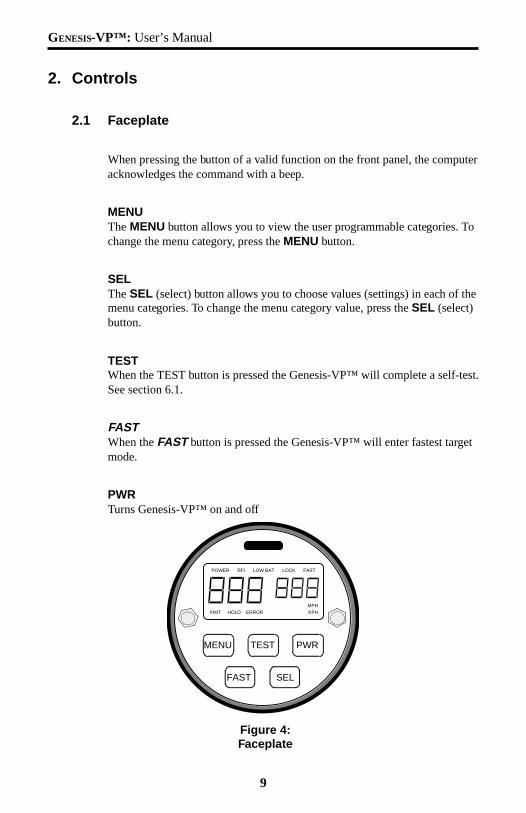
2.1 Faceplate
When pressing the button of a valid function on the front panel, the computeracknowledges the command with a beep.
MENUThe MENU button allows you to view the user programmable categories. Tochange the menu category, press the MENU button.
SELThe SEL (select) button allows you to choose values (settings) in each of themenu categories. To change the menu category value, press the SEL (select)button.
TESTWhen the TEST button is pressed the Genesis-VP™ will complete a self-test.See section 6.1.
FASTWhen the FAST button is pressed the Genesis-VP™ will enter fastest targetmode.
PWRTurns Genesis-VP™ on and off
Figure 4:Faceplate
MENU TEST PWR
FAST
POWER RFI LOW BAT LOCK FAST
MPHXMIT HOLD ERROR KPH
SEL
GENESIS-VP™: User’s Manual
10
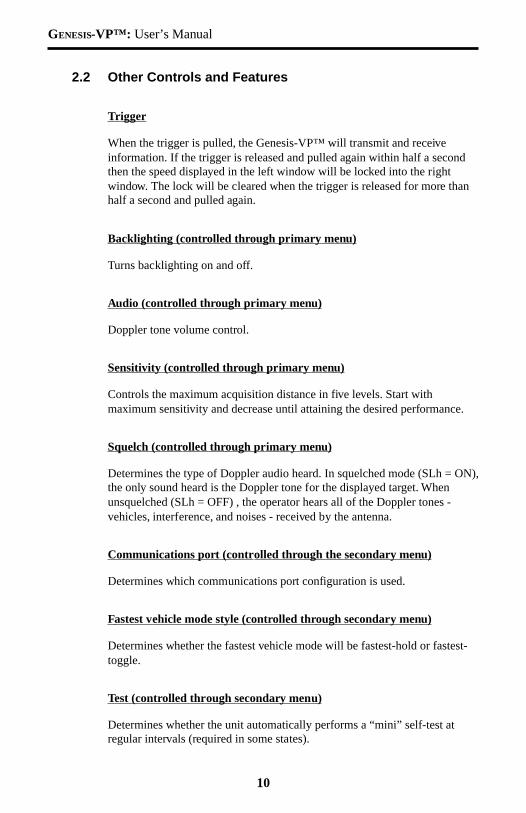
2.2 Other Controls and Features
Trigger
When the trigger is pulled, the Genesis-VP™ will transmit and receiveinformation. If the trigger is released and pulled again within half a secondthen the speed displayed in the left window will be locked into the rightwindow. The lock will be cleared when the trigger is released for more thanhalf a second and pulled again.
Backlighting (controlled through primary menu)
Turns backlighting on and off.
Audio (controlled through primary menu)
Doppler tone volume control.
Sensitivity (controlled through primary menu)
Controls the maximum acquisition distance in five levels. Start withmaximum sensitivity and decrease until attaining the desired performance.
Squelch (controlled through primary menu)
Determines the type of Doppler audio heard. In squelched mode (SLh = ON),the only sound heard is the Doppler tone for the displayed target. Whenunsquelched (SLh = OFF) , the operator hears all of the Doppler tones -vehicles, interference, and noises - received by the antenna.
Communications port (controlled through the secondary menu)
Determines which communications port configuration is used.
Fastest vehicle mode style (controlled through secondary menu)
Determines whether the fastest vehicle mode will be fastest-hold or fastest-toggle.
Test (controlled through secondary menu)
Determines whether the unit automatically performs a “mini” self-test atregular intervals (required in some states).
11
GENESIS-VP™: User’s Manual
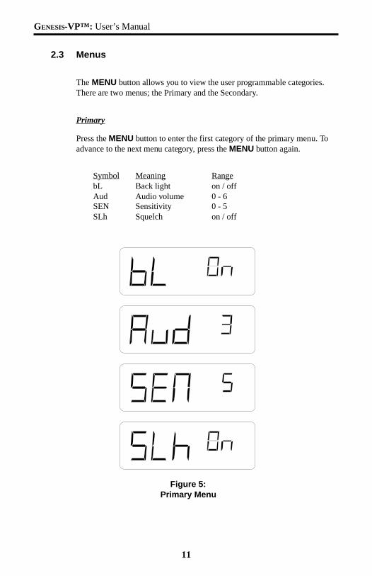
2.3 Menus
The MENU button allows you to view the user programmable categories.There are two menus; the Primary and the Secondary.
Primary
Press the MENU button to enter the first category of the primary menu. Toadvance to the next menu category, press the MENU button again.
Symbol Meaning RangebL Back light on / offAud Audio volume 0 - 6SEN Sensitivity 0 - 5SLh Squelch on / off
Figure 5:Primary Menu
GENESIS-VP™: User’s Manual
12
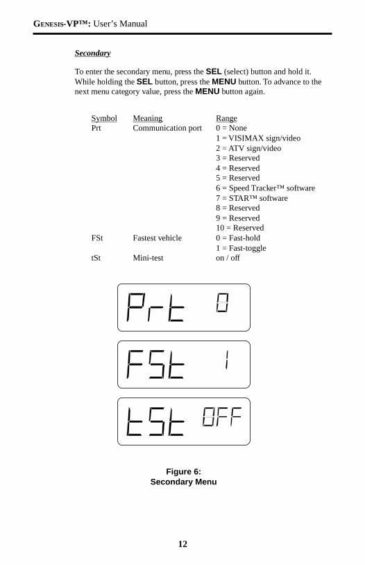
Secondary
To enter the secondary menu, press the SEL (select) button and hold it.While holding the SEL button, press the MENU button. To advance to thenext menu category value, press the MENU button again.
Symbol Meaning RangePrt Communication port 0 = None
1 = VISIMAX sign/video2 = ATV sign/video3 = Reserved4 = Reserved5 = Reserved6 = Speed Tracker™ software7 = STAR™ software8 = Reserved9 = Reserved10 = Reserved
FSt Fastest vehicle 0 = Fast-hold1 = Fast-toggle
tSt Mini-test on / off
Figure 6:Secondary Menu
13
GENESIS-VP™: User’s Manual
NOTES:
1. The Genesis-VP™ will exit menu mode if neither the MENU or SELbuttons are pressed for two seconds. If either the MENU or SEL buttons areheld, the Genesis-VP™ will stay in menu mode.
2. The primary menu functions in real time. The Genesis-VP™ will continueto transmit accurate audio and serial communications while in menu mode. Asystem reset will always occur when exiting the secondary menu.
3. The unit will “remember” the last settings when turned off and will powerup with the last set values in each category.
GENESIS-VP™: User’s Manual
14
3. Displays
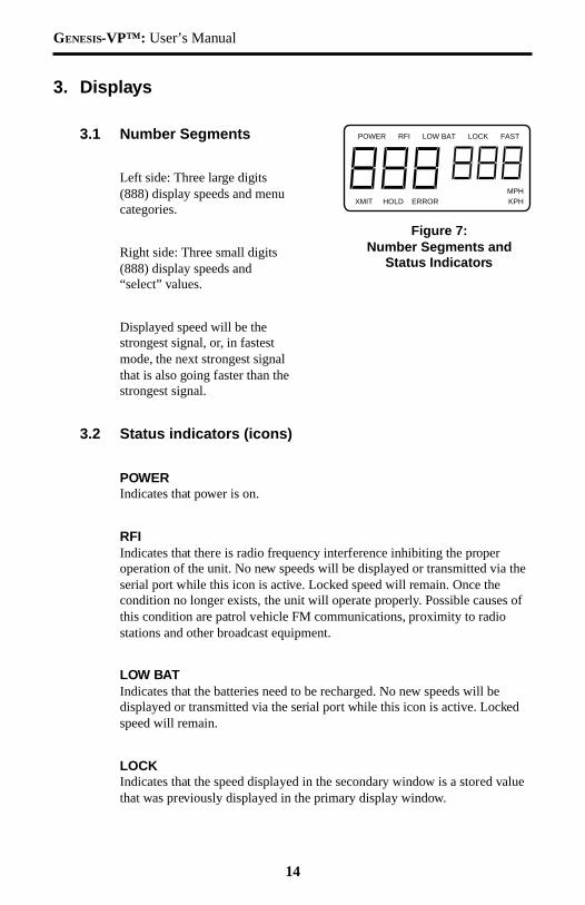
3.1 Number Segments
Left side: Three large digits(888) display speeds and menucategories.
Right side: Three small digits(888) display speeds and“select” values.
Displayed speed will be thestrongest signal, or, in fastestmode, the next strongest signalthat is also going faster than thestrongest signal.
3.2 Status indicators (icons)
POWERIndicates that power is on.
RFIIndicates that there is radio frequency interference inhibiting the properoperation of the unit. No new speeds will be displayed or transmitted via theserial port while this icon is active. Locked speed will remain. Once thecondition no longer exists, the unit will operate properly. Possible causes ofthis condition are patrol vehicle FM communications, proximity to radiostations and other broadcast equipment.
LOW BATIndicates that the batteries need to be recharged. No new speeds will bedisplayed or transmitted via the serial port while this icon is active. Lockedspeed will remain.
LOCKIndicates that the speed displayed in the secondary window is a stored valuethat was previously displayed in the primary display window.
POWER RFI LOW BAT LOCK FAST
MPHXMIT HOLD ERROR KPH
Figure 7:Number Segments and
Status Indicators
15
GENESIS-VP™: User’s Manual
FASTIndicates that the Genesis-VP™ is in fast mode. When not in fast mode, theGenesis-VP™ is assumed to be in strongest signal mode (the default mode).The Genesis-VP™ is capable of internally tracking multiple speedssimultaneously. Each vehicle return signal is ranked by its strength andspeed.
XMITIndicates that the Genesis-VP™ is transmitting.
HOLDIndicates that the Genesis-VP™ is not transmitting.
ERRORIndicates that the Genesis-VP™ has suffered an internal hardware errorwhich could affect the operation of the unit. Please contact DecaturElectronics, Inc. for instructions. 1.800.428.4315.
MPHThe MPH icon is not used. The Genesis-VP™ is assumed to be displayingspeeds in miles per hour.
KPHIndicates that the Genesis-VP™ is displaying speeds in kilometers per hour.
GENESIS-VP™: User’s Manual
16
4. Modes of Operation
4.1 Strongest signal mode
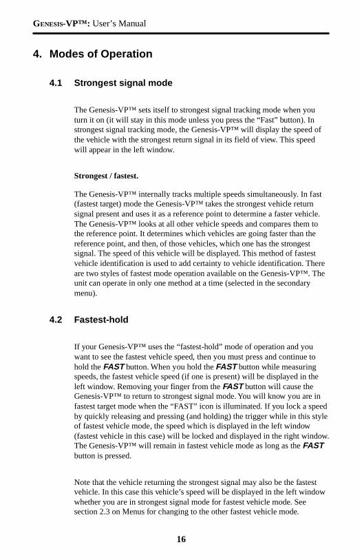
The Genesis-VP™ sets itself to strongest signal tracking mode when youturn it on (it will stay in this mode unless you press the “Fast” button). Instrongest signal tracking mode, the Genesis-VP™ will display the speed ofthe vehicle with the strongest return signal in its field of view. This speedwill appear in the left window.
Strongest / fastest.
The Genesis-VP™ internally tracks multiple speeds simultaneously. In fast(fastest target) mode the Genesis-VP™ takes the strongest vehicle returnsignal present and uses it as a reference point to determine a faster vehicle.The Genesis-VP™ looks at all other vehicle speeds and compares them tothe reference point. It determines which vehicles are going faster than thereference point, and then, of those vehicles, which one has the strongestsignal. The speed of this vehicle will be displayed. This method of fastestvehicle identification is used to add certainty to vehicle identification. Thereare two styles of fastest mode operation available on the Genesis-VP™. Theunit can operate in only one method at a time (selected in the secondarymenu).
4.2 Fastest-hold
If your Genesis-VP™ uses the “fastest-hold” mode of operation and youwant to see the fastest vehicle speed, then you must press and continue tohold the FAST button. When you hold the FAST button while measuringspeeds, the fastest vehicle speed (if one is present) will be displayed in theleft window. Removing your finger from the FAST button will cause theGenesis-VP™ to return to strongest signal mode. You will know you are infastest target mode when the “FAST” icon is illuminated. If you lock a speedby quickly releasing and pressing (and holding) the trigger while in this styleof fastest vehicle mode, the speed which is displayed in the left window(fastest vehicle in this case) will be locked and displayed in the right window.The Genesis-VP™ will remain in fastest vehicle mode as long as the FASTbutton is pressed.
Note that the vehicle returning the strongest signal may also be the fastestvehicle. In this case this vehicle’s speed will be displayed in the left windowwhether you are in strongest signal mode for fastest vehicle mode. Seesection 2.3 on Menus for changing to the other fastest vehicle mode.
17
GENESIS-VP™: User’s Manual
4.3 Fastest-toggle
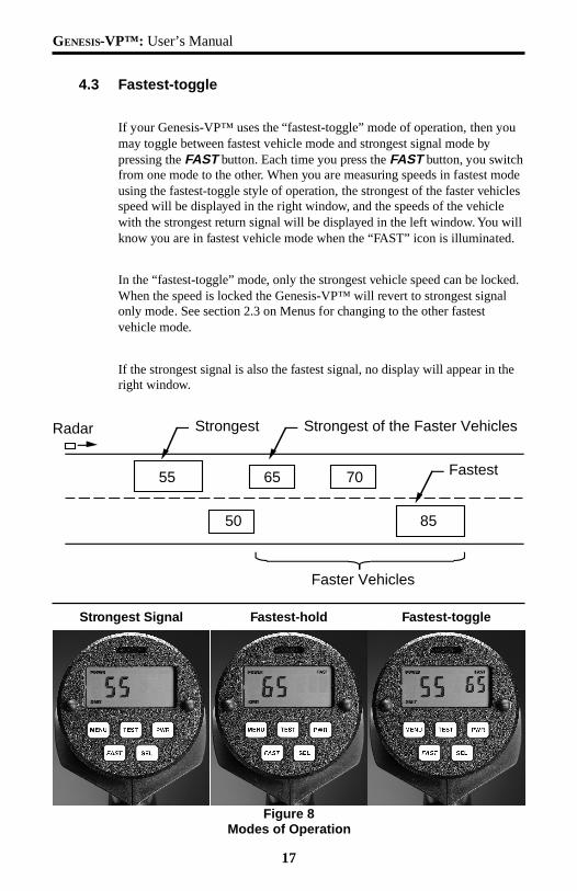
If your Genesis-VP™ uses the “fastest-toggle” mode of operation, then youmay toggle between fastest vehicle mode and strongest signal mode bypressing the FAST button. Each time you press the FAST button, you switchfrom one mode to the other. When you are measuring speeds in fastest modeusing the fastest-toggle style of operation, the strongest of the faster vehiclesspeed will be displayed in the right window, and the speeds of the vehiclewith the strongest return signal will be displayed in the left window. You willknow you are in fastest vehicle mode when the “FAST” icon is illuminated.
In the “fastest-toggle” mode, only the strongest vehicle speed can be locked.When the speed is locked the Genesis-VP™ will revert to strongest signalonly mode. See section 2.3 on Menus for changing to the other fastestvehicle mode.
If the strongest signal is also the fastest signal, no display will appear in theright window.
Fastest-toggleStrongest Signal Fastest-hold
Figure 8Modes of Operation
55 65 70
50 85
Radar Strongest Strongest of the Faster Vehicles
Fastest
Faster Vehicles
GENESIS-VP™: User’s Manual
18
5. Serial Communications Option
If your Genesis-VP™ has a communications connector on the side, you mayconnect it to Decatur’s large display signs, in-car video, or a PersonalComputer which is running Decatur Electronics’ software. If connecting to aPersonal Computer, plug the 9-pin end (DB-9 connector) of the computercable into the serial communications port on your computer. Use the cable(s)that come with the sign or software (if purchased). Make sure you select thecorrect value under “port” on the secondary menu.
6. Field Tests
There are two field tests to verify the accuracy of the GENESIS-VP™.
6.1 Self test
Pressing the TEST button on the display initiates a system self-test. This testchecks the left and right numeric displays and runs a simulation of the targetspeeds. The Genesis-VP™ will not power down while a self-test is inprocess.
Display (LCD) test
The segments in the left and right displays will be illuminated in a circularpattern to test for faulty Liquid Crystal segments.
Circuitry (DSP) test
The Digital Signal Processor will be tested. “PASS” or “FAIL” will appearon the display when test is completed.
Speed simulation
The Genesis-VP™ verifies vehicle speed acquisition using synthesizedDoppler frequencies corresponding to the series of four speeds listed below.“PASS” or “FAIL” will appear on the display when test is completed.
The speeds are:
MPH 15, 30, 45, 60 (if your Genesis-VP™ is in MPH)KPH 25, 50, 75, 100 (if your Genesis-VP™ is in KPH)
19
GENESIS-VP™: User’s Manual
6.2 Tuning Fork Test
NOTE: Keep Trigger pressed during entire test.
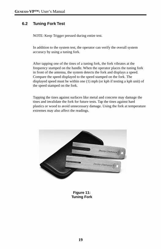
In addition to the system test, the operator can verify the overall systemaccuracy by using a tuning fork.
After tapping one of the tines of a tuning fork, the fork vibrates at thefrequency stamped on the handle. When the operator places the tuning forkin front of the antenna, the system detects the fork and displays a speed.Compare the speed displayed to the speed stamped on the fork. Thedisplayed speed must be within one (1) mph (or kph if testing a kph unit) ofthe speed stamped on the fork.
Tapping the tines against surfaces like metal and concrete may damage thetines and invalidate the fork for future tests. Tap the tines against hardplastics or wood to avoid unnecessary damage. Using the fork at temperatureextremes may also affect the readings.
Figure 11:Tuning Fork
GENESIS-VP™: User’s Manual
20
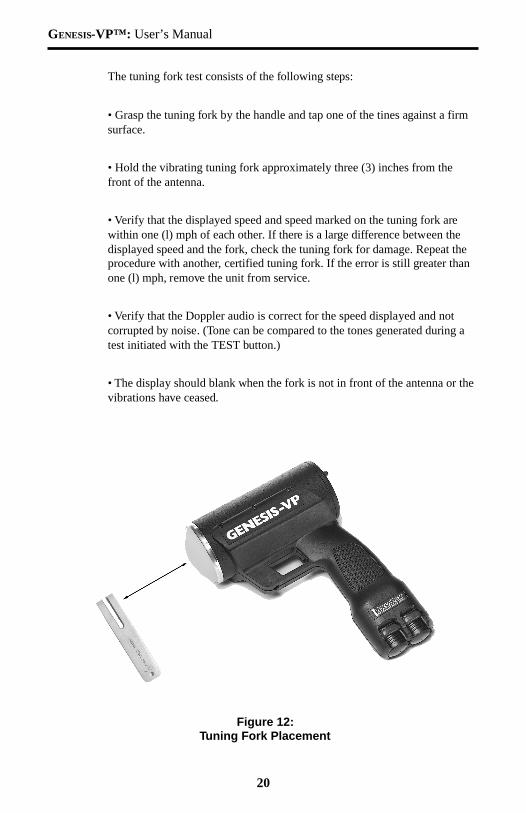
The tuning fork test consists of the following steps:
• Grasp the tuning fork by the handle and tap one of the tines against a firmsurface.
• Hold the vibrating tuning fork approximately three (3) inches from thefront of the antenna.
• Verify that the displayed speed and speed marked on the tuning fork arewithin one (l) mph of each other. If there is a large difference between thedisplayed speed and the fork, check the tuning fork for damage. Repeat theprocedure with another, certified tuning fork. If the error is still greater thanone (l) mph, remove the unit from service.
• Verify that the Doppler audio is correct for the speed displayed and notcorrupted by noise. (Tone can be compared to the tones generated during atest initiated with the TEST button.)
• The display should blank when the fork is not in front of the antenna or thevibrations have ceased.
Figure 12:Tuning Fork Placement
21
GENESIS-VP™: User’s Manual
7. Care, Cleaning, and Storage
Do not spill food, beverages or other liquids and substances on the Genesis-VP™. When the Genesis-VP™ is not in use or when it is being transported,store it in its original packaging. To clean the Genesis-VP™, dust it lightlywith a soft clean cloth. The cloth should be free from any cleaning solutions.
8. Limitations to Doppler RADAR
When properly used, the Doppler radar system is extremely accurate andreliable. However, the variations in the environment can cause situations andcircumstances which may create speeds that appear incorrect.
8.1 Cosine Effect
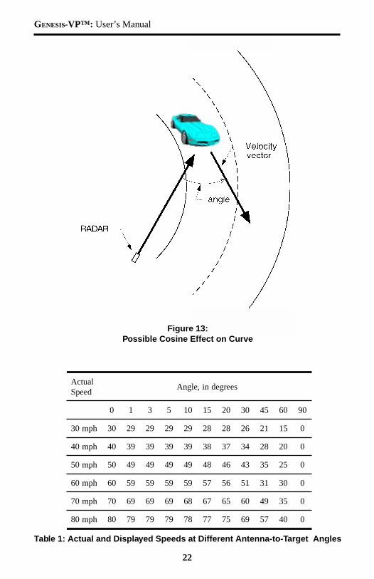
The cosine effect causes the system to display a speed that is lower thanactual vehicle speed. This condition exists whenever the target vehicle’s pathis not parallel to the antenna, including curves and hills. In all uses of policeradar, there is always a slight angle between the patrol and target vehicle toavoid collisions.
Whenever the angle between the beam of the antenna and the target vehicleincreases, the displayed speed decreases. Ideally, an angle of zero (0) degreesis preferable, since the displayed speed will be the actual target vehiclespeed. The following table shows the effects that an increasing angle canhave on the speed displayed.
At angles less than 10°, there is not much difference between the target andactual speed. As the angle increases, the error increases. At 90°, the TARGETspeed is zero mph - grossly incorrect.
GENESIS-VP™: User’s Manual
22
Table 1: Actual and Displayed Speeds at Different Antenna-to-Target Angles
lautcAdeepS
seergedni,elgnA
0 1 3 5 01 51 02 03 54 06 09
hpm03 03 92 92 92 92 82 82 62 12 51 0
hpm04 04 93 93 93 93 83 73 43 82 02 0
hpm05 05 94 94 94 94 84 64 34 53 52 0
hpm06 06 95 95 95 95 75 65 15 13 03 0
hpm07 07 96 96 96 86 76 56 06 94 53 0
hpm08 08 97 97 97 87 77 57 96 75 04 0
Figure 13:Possible Cosine Effect on Curve
23
GENESIS-VP™: User’s Manual
8.2 Interference
Radar systems, like any other radio system, are subject to externalinterference. The two most common kinds are radio frequency interferenceand undesired moving objects.
Radio Frequency
The system may inadvertently process radio frequency energy from airportradar, streetlights, high-tension power lines, microwave transmission towers,CB radio transmitters, and AM/FM transmission towers as Doppler speeds.The Genesis-VP™ unit has a radio frequency interference (RFI) detectioncircuit, designed to detect excess radio frequency energy. When stray radiofrequency energy reaches an excessive level, the system will illuminate the“RFI” icon in the display. Once the source of radio interference ends, thesystem will resume normal operation. Also, any locked speeds will return tothe lock window.
Moving Objects
The system may also detect other moving objects in the antenna’s beam. Fanblades, in the patrol vehicle, can generate undesired Doppler signals.
Since these signals can be similar to moving cars, the operator needs todiscern between a valid target and a source of interference. Usually, a sourceof moving interference exhibits the following characteristics:
• A reading when there is not a target vehicle in the operational range ofthe antenna.
• A target vehicle, upon entering the operational range, will override theinterference signal-causing the displayed speed to change suddenly.
• The Doppler audio will be corrupted with noise, unlike a good, clearDoppler tone.
• Interference is irregular and does not provide a valid tracking history.
GENESIS-VP™: User’s Manual
24
8.3 Multi-path Beam Cancellation
When multi-path beam cancellation occurs, the target vehicle speed displaywill sporadically blank and reappear. This occurs when the radar looses trackof a target vehicle at semi-random intervals. The target vehicle is reflectingtwo signals that are interfering with one another. When the phase of the twosignals is 180°, maximum interference occurs and the signals cancel, causingthe system to ignore the target vehicle. When there is only one target vehicle,the system will reacquire the speed of the vehicle. However, when moretarget vehicles are present, the system could lock onto another vehicle. Theoperator can minimize the confusion of multi-path beam cancellation with anaccurate tracking history of the original target vehicle.
8.4 Scanning
All radar antennas, for police applications, are designed to be operated froma fixed mounting, or to be hand-held in a steady position. Moving or“scanning” the antenna past stationary objects can cause the system to detectthe motion. A speed-reading obtained from scanning requires deliberatemisuse.
25
GENESIS-VP™: User’s Manual
9. Warranty
TWO YEAR RADAR WARRANTY
Decatur Electronics, Inc. guarantees the Genesis-VP™ to be free fromdefects in workmanship and material, and to operate within specifications fora period of two years. During this period, Decatur Electronics, Inc. willrepair or replace, at its option, any component, except batteries or chargers,found to be defective, without cost to the owner, provided the unit is returnedto the factory.
The full warranty on parts and workmanship does not include normal wearand tear, crushing, dropping, fire, impact, immersion, or damage fromattempted repair or modifications by unauthorized service agents.
Simply return the unit (transportation prepaid) directly to the factory or to anAuthorized Decatur Electronics Warranty Service Center near you.
If you have any questions, or want a quick problem diagnosis, please call ourcustomer service hot-line and ask for the service department:
phone: 1.800.428.4315
fax: 1.217.428.5302
TWO YEAR WARRANTY EXCEPTION
If the unit was purchased under a special buying program (state purchasecontract, etc.), then the above warranty may not apply. Please refer to thebuying program contract for the appropriate warranty terms, or contactDecatur Electronics, Inc. at the above phone number.
EXTENDED WARRANTY OPTIONS
If you are interested in an extended warranty, contact your salesrepresentative to discuss extended warranty options.
GENESIS-VP™: User’s Manual
26
10.Service Return Procedure
If it becomes necessary to return the Genesis-VP™ to the factory, pleasefollow the procedure below:
• Return ALL pieces of the Genesis-VP™ in the original packaging
• Include a note describing the malfunction of the system, or the incidentthat resulted in a malfunction. Failure to do so may delay the return ofthe system.
• Telephone the Customer Service Department, at Decatur Electronics: 1-800-428-4315, to obtain a return authorization (RA) number. Write theRA number on the note and shipping label.
• Return the system to:
Decatur Electronics, Inc.715 Bright StreetDecatur, IL 62522 USARA#: xxxxxx
The shipping charges, for sending the system to Decatur Electronics, Inc., arethe responsibility of the customer.
If a system, still under warranty, is received COD from a customer, thecustomer will be charged for the amount of the COD freight charges plus anadditional 10% for handling, after the system is repaired. The COD and 10%handling fee will be added to the repair bill as out-of-warranty repairs.
Decatur Electronics, Inc. will pay the freight (up to $10.00 US) for shipmentof the system from the repair facility to the customer, provided that thesystem is still under warranty. Any shipping charges, above the initial $10.00,will be charged to the customer. If Express or Next Day Air is desired, thecustomer will be invoiced for the freight charges, even if the system is stillunder warranty.
An estimate can be furnished for repairs that are out-of-warranty, at thecustomer’s request, for $50.00 US. Even if the customer decides to not havethe repairs completed, they will be invoiced for the $50.00, plus returnfreight. If Decatur Electronics proceeds with the repairs, there will be nocharge for the estimate.
27
GENESIS-VP™: User’s Manual
Appendix 1, Specifications
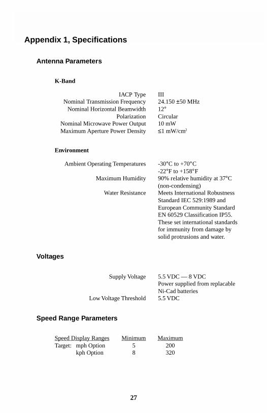
Antenna Parameters
K-Band
IACP Type IIINominal Transmission Frequency 24.150 ±50 MHz
Nominal Horizontal Beamwidth 12°Polarization Circular
Nominal Microwave Power Output 10 mWMaximum Aperture Power Density ≤1 mW/cm2
Environment
Ambient Operating Temperatures -30°C to +70°C-22°F to +158°F
Maximum Humidity 90% relative humidity at 37°C(non-condensing)
Water Resistance Meets International RobustnessStandard IEC 529:1989 andEuropean Community StandardEN 60529 Classification IP55.These set international standardsfor immunity from damage bysolid protrusions and water.
Voltages
Supply Voltage 5.5 VDC — 8 VDCPower supplied from replacableNi-Cad batteries
Low Voltage Threshold 5.5 VDC
Speed Range Parameters
Speed Display Ranges Minimum MaximumTarget: mph Option 5 200
kph Option 8 320
GENESIS-VP™: User’s Manual
28
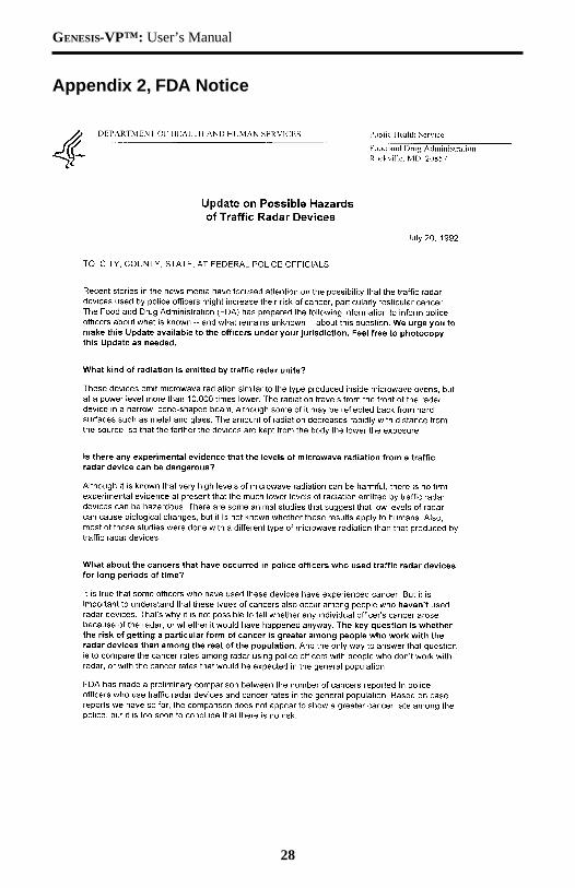
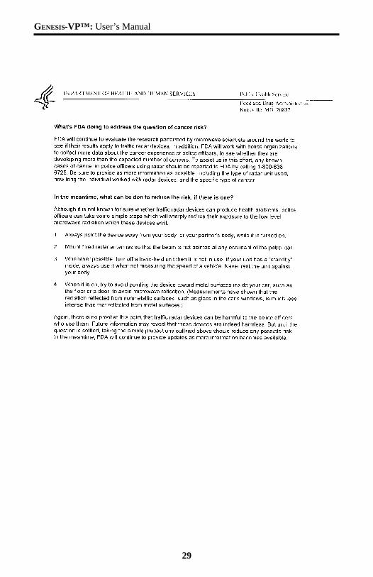
Appendix 2, FDA Notice
29
GENESIS-VP™: User’s Manual
GENESIS-VP™: User’s Manual
30
Appendix 3, FCC/ISC Documents
This page reserved for Grant of Equipment Authorization.
Note: This equipment has been tested and found to comply with the limits ofa Class B digital device, pursuant to part 15 of the FCC rules. These limitsare designed to provide reasonable protection against harmful interference inresidential installation. This equipment generates, uses and can radiate radiofrequency energy and, if not installed and used in accordance with theinstructions, may cause harmful interference to radio communications.However, there is no guarantee that interference will not occur in a particularinstallation. If this equipment does cause harmful interference to radio ortelevision reception which can be determined by turning the equipment offand on, the user is encouraged to try to correct the interference by one ormore of the following measures:
• Reorient or relocate the receiving antenna• Increase the separation between the equipment and receiver• Connect the equipment into an outlet on a circuit that is different
from that which the receiver is connected• Consult the dealer or an experienced radio/TV technician for help.
31
GENESIS-VP™: User’s Manual
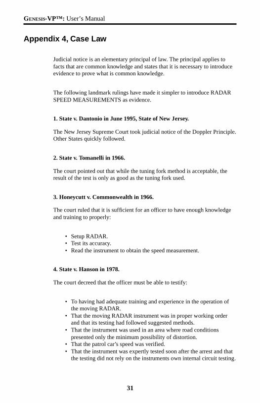
Appendix 4, Case Law
Judicial notice is an elementary principal of law. The principal applies tofacts that are common knowledge and states that it is necessary to introduceevidence to prove what is common knowledge.
The following landmark rulings have made it simpler to introduce RADARSPEED MEASUREMENTS as evidence.
1. State v. Dantonio in June 1995, State of New Jersey.
The New Jersey Supreme Court took judicial notice of the Doppler Principle.Other States quickly followed.
2. State v. Tomanelli in 1966.
The court pointed out that while the tuning fork method is acceptable, theresult of the test is only as good as the tuning fork used.
3. Honeycutt v. Commonwealth in 1966.
The court ruled that it is sufficient for an officer to have enough knowledgeand training to properly:
• Setup RADAR.• Test its accuracy.• Read the instrument to obtain the speed measurement.
4. State v. Hanson in 1978.
The court decreed that the officer must be able to testify:
• To having had adequate training and experience in the operation ofthe moving RADAR.
• That the moving RADAR instrument was in proper working orderand that its testing had followed suggested methods.
• That the instrument was used in an area where road conditionspresented only the minimum possibility of distortion.
• That the patrol car’s speed was verified.• That the instrument was expertly tested soon after the arrest and that
the testing did not rely on the instruments own internal circuit testing.
GENESIS-VP™: User’s Manual
32
Notes

33
GENESIS-VP™: User’s Manual

GENESIS-VP™: User’s Manual
34