Embed Size (px)
Citation preview
DECONSTRUCTING THE ARTIFICIAL LIFT GAP: THE CONSEQUENCES OF LIFT SYSTEM TRANSITION
ON PER BARREL COST
Dave Kimery
Production Plus Energy Services Inc.
Camille Jensen
Production Plus Energy Services Inc.
Jeff Saponja
Production Plus Energy Services Inc.
INTRODUCTION
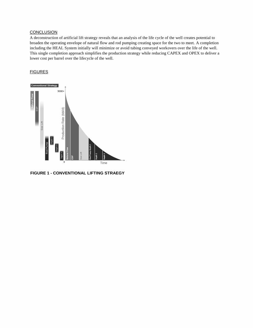
It is common practice in horizontal wells to transition through multiple artificial lift systems. For example, shifting
through lifting systems such as ESP, gas lift and rod pumping along with changes in rod pump depths are
conventional practice for many operations (Figure 1). Persistent changes require several planned workovers while
challenged operating practices at each stage increase the necessity for unplanned workovers to ameliorate reliability
issues. For wells characterized by excessive depth, high pressure and with high liquid and gas rates, a reliability
versus drawdown trade-off taxes per barrel CAPEX and OPEX. An example of a typical unconventional horizontal
oil well is shown in Figure 2.
Historically, operators attempt to offset costs by transitioning to rod pumping as soon as possible. Rod pumping is
often the most reliable option at the lowest cost per barrel, so a desirable transition. However, for deep higher rate
horizontals, typical of unconventional plays, rod pumping alone cannot bridge the gap between natural flow or high
volume ESPs; therefore, a phase of gas lift is today’s norm.
OPTIMUM PRODUCTION STRATEGY
Technical limitations, existing cost structures and the characteristics of the reservoir all impact an optimum
production strategy. There is no single, simple calculation or solution to solve all production situations. Rather, there
are several artificial lift strategies and possible combinations that may achieve desired results within an acceptable
range. Sometimes the technical envelopes and capabilities of artificial lift systems overlap and sometimes they do
not. One situation may require filling a lifting gap while another scenario may hinge on the most efficient time to
switch artificial lift systems. How to combine systems and effectively switch systems while producing the most oil
at the lowest cost per barrel, is not a simple task for the Production Engineer.i
NATURAL FLOW
Natural flow occurs when the reservoir pressure exceeds the total pressure loss through the wellbore from the
reservoir level to surface, both hydrostatic and frictional, plus any pressure applied at surface. This occurs in two
conditions:
Normally or overpressured reservoirs where the full hydrostatic column of the reservoir fluids exerts a
pressure that is less than the reservoir pressure. Many unconventional reservoirs are overpressured, thus,
typically have at least a short period of natural flow due to this phenomenon.
Sufficient gas production that the fluid velocity in the wellbore is adequate to transport produced liquids to
surface, typical referred to as the ‘critical rate’ for lifting liquids.
A simplified method for calculating where this condition exists was presented by Turner et alii. The Turner
correlation can relate the critical rate to the reservoir fluid properties, surface pressure and cross-sectional area of the
flowpath of those fluids. A plot of the Turner correlation critical rate for the type well illustrated in Figure 2 is
shown in Figure 3.
For horizontal wells, the multiphase flow mechanics are more complicated. A more robust method involves using
the Tubing Performance Curve (TPC), often referred to as Vertical Lift Performance (VLP) Curves or J-Curvesiii
(see Figure 4). Generation of the TPC involves the rigorous simulation of the multiphase flow through the entire
well to generate bottomhole pressure curves versus gas or liquid production rates. The curves are made up of a
gravity (or hydrostatic) component and a frictional component. The downward sloping side of the curve is
commonly referred to as ‘hydrostatically dominated’ and is characterized by erratic, sluggy and unstable flow. The
upward sloping section to the right is commonly referred to as ‘frictionally dominated’, characterized by the annular
mist flow regime and is inherently stable. For a well to flow naturally to surface the gas production rate must exceed
this critical production rate or else the well will slug, load up and die.
The shape of these curves, for fixed fluid properties and watercuts, can be modified by changing the internal
diameter (ID) of the production tubing (see Figure 5). For smaller diameter tubing, the frictional pressure drop is
higher resulting in higher producing bottomhole pressure. However, larger tubing where the frictional pressure drop
is lower requires higher gas production rates to enter the frictionally dominated regime, and therefore, require higher
gas production rates to flow naturally. In designing the tubing string for the natural flow period, there is a trade-off
between maximizing production rate in the early stages of the well and the length of time the well will flow
naturally before artificial lift is required.
Based upon the principles above and the type well properties, it is possible to estimate the range where the well will
naturally flow. This is important for planning the next phase of the well’s production life since the upper end of the
range where the next artificial lift system is installed should be close to, or overlap with, the lower end range where
the well is expected to flow naturally (see Figure 6).
ROD PUMPING
In an ideal situation, rod pumping is industry proven as cost-effective and reliable. Rod pumps are highly efficient
over a broad operating envelope of production rates and depths. They are compatible with multiple completions and
slimhole wells. Rod pumps are mechanically simple; therefore, tend to be easier for operators to operate close to
optimum conditions. There are some drawbacks and limitations with rod pumping. They are challenged by gas
interference, solids production, paraffin and scale; however, corrosion, paraffin and scale treatments are available.
Rod pumping is known to be less efficient when the pump is placed in the deviated section of the wellbore.
Disadvantages aside, rod pumping continues to be the first choice for many operators.iv
When installing a rod pumping system, it is preferable to place the pump as low as possible so as to maximize the
drawdown achievable, thereby maximizing production rate and reserves. However, there is a trade-off in depth of
the pump and the rod pumping equipment size and cost. Typically, however, the pump depth needs to be close to, if
not at, the kick-off point of the well in order to be able to achieve the same drawdown as was realized at the end of
the natural flow period in order to maintain a smooth transition in production rates.
Figure 7 shows the rate capability of a rod pumping system in the type well at various pump depths: at a typical
location in the build section used to maximize drawdown, at the kick-off point, and above the kick-off point in the
vertical section. The figure illustrates how the production capacity of a rod pump system rapidly diminishes with
increased depth, especially once placed in the build section. The figure shows what is practically achievable with a
conventional pumpjack, insert pump and steel rod string, what is possibly achievable with very large pumpjacks
and/or tubing pumps, and what rates are not achievable at those depths.
It should also be noted that the pump rate ratings listed in the figure for the type well are for high volumetric
efficiency (85% efficiency typical seen taking into account slippage and shrinkage) and 100% fillage. Horizontal oil
wells with higher GORs such as specified in the type well are notorious for severe gas interference effects, even
with downhole separation, due to the sluggy, erratic production behaviour of the fluid flow from the horizontal
section of the wellbore. The achievable rates in practice tend to be 60% or less than the values in the table because
of incomplete fillage and gas locking issues.
Based upon the predicted range where natural flow will terminate and the upper range of rod pumping taking into
account incomplete fillage and gas locking, taking a well from natural flow to rod pumping will either lead to a step-
change drop in production rate versus the previous trend, or require multiple tubing conveyed workovers to lower
the pump over time and maximize the rate out of the well with a practically sized pumpjack.
THE LIFTING GAP
The shift from selecting an artificial lift system to developing an artificial lift strategy lies in the analysis of lifting
costs per barrel over time. Figure 1 illustrated the introductory discussion and shows the typical pattern of deeper
horizontals that are likely to require a set of artificial lift systems to maximize drawdown. The end stages of one
system and the initial stages of the next have the propensity toward unplanned workovers caused from maintenance
and troubleshooting requirements resulting in reliability issues. Notice that, from Figure 6 and Figure 7, for deep
high-rate horizontals, the bottom end of natural flow does not align with the top end of rod pumping. This trade-off
between reliability and drawdown risks excessive lifting cost per barrel. An effective artificial lift strategy
capitalizes on both reliability and drawdown. To do this, deeper analysis and deconstruction of the artificial lifting
gap follows.
GAS LIFT
Over time and experience across the industry, gas lift has become common practice to fill the lifting gap for the
deep, high rate horizontal wells. For all intents and purposes, gas lift is the extension of the natural flow period
where the injected gas makes up for the shortfall in produced gas to get the well above the critical rate required to
naturally flow to surface.
There are intrinsic benefits of gas lift. It is solids tolerant and manages gas interference. Deviated wells present no
issues and corrosion is not a typical problem. Gas lift is attractive since it has the capacity to lift deep wells with a
broad technical operating window. For operators with infrastructure and equipment already in place, gas lift is an
easy and obvious solution.v
Although gas lift is reliable and can handle high initial production declines, it is limited by high bottomhole
pressures, limiting drawdown, and thus production. Because of the long run of tubing, gas expansion nearing the
surface causes excessive frictional pressure losses which limits drawdown (as demonstrated in Figure 4). The deeper
the well, the more restricted drawdown becomes in a gas lift environment. For deep wells, in particular, gas lift
cannot effectively produce to desired abandonment pressures.
As an example, for the type well in a natural flow or gas lift scenario, the lowest producing bottomhole pressure is
around 850 psi (see Figure 8). At some point in the life cycle, the well is forced to move from gas lift to another
artificial lift solution, such as rod pumping, in order to further increase drawdown and produce at a rate that can
economically access the remaining reserves.
From a cost perspective, gas lift incurs high costs to compress gas for the process, to install infrastructure and to
purchase gas (when required). Further, operators without infrastructure in place face a high economic burden of
equipment and the operating expense necessary for high gas injection pressures and rates.
The combination of these contravening factors—infrastructure and gas costs, operating expenses, high bottomhole
pressures, inadequate production at low reservoir pressures, limited drawdown—necessitates the shift to another
artificial lift system. The ideal scenario would eliminate intermediate lifting altogether and install one system for the
life of the well.
TAMING SLUGGY FLOW FROM THE HORIZONTAL TO CLOSE THE LIFTING GAP
Conventional lifting methods have proven workable, yet perhaps not as efficient and economical as the environment
allows. Analyzing the root cause of lifting inefficiency, however, leads to a new understanding of efficiency.
Horizontal wells are characterized by sluggy and inconsistent flow that presents as rapidly fluctuating gas and liquid
rates and surges. This complex fluid flow behavior creates an environment for gas interference in the pump, is the
mechanism for transporting pump damaging solids along a horizontal wellbore, and is a highly likely root cause
mechanism for encouraging undesirable proppant flowback into the wellbore. Gas lift moderately addresses both of
these issues. The transition away from gas lift to another artificial lift system not capable of handling gas
interference or solids results in a struggling artificial lift system with reduced runtime and reliability, excessive
workover costs and limited drawdown.
For the deep, high gas liquid ratio wells, an environment that supports fluid moving at a critical velocity through the
entire production string while managing solids offers the potential for both economic efficiency and production
efficiency. Production Plus Energy Services Inc. applied the benefits of gas lift, underbalanced drilling multiphase
flow conditioning practices, research, field testing and operator experience to develop a new technology, the HEAL
System, that successfully fills this artificial lift gap.
The HEAL System actualizes the benefits of the mid-section of gas lift by lowering a section of production tubing
into the bend and reducing tubing internal diameter to achieve critical velocity and fluid flow stabilization from the
horizontal to above the kick-off point. In turn, a conventional artificial lift system can be placed higher and out of
the bend, in the vertical where it is designed to be most efficient and reliable.
The system is a mechanical system comprised of three main components: a HEAL Seal, a sized regulating string
(SRS), and a HEAL Vortex Separator (see Figure 9). The SRS has a sized internal diameter and length specific to
the reservoir pressures and anticipated production rates over the well’s life cycle. Like gas lift, the HEAL System is
designed to minimize operational risk and maximize reliability, with no moving parts and does not extend into the
horizontal.
How it worksvi
Production from the horizontal is conditioned up the sized regulating string, smoothing flow and reducing density
which results in increased drawdown. Smoothened flow from the sized regulating string is discharged to the well’s
annulus by the HEAL Vortex Separator, which is placed near or above the kick-off point. The combination of
smooth flow and the cyclonic effect of the Vortex Separator results in highly efficient separation of gas and solids
from the liquid, which protects the pump from gas interference, damage or seizing from solids (see Figure 9).
The HEAL Seal consists of a floating non-latching seal that forces all of the production from the horizontal section
into the SRS through the build section of the well. The production from the horizontal flows up the SRS. The SRS is
designed with variable internal diameters to put the flow from the horizontal into a conditioned multiphase state,
both smoothing flow and lowering fluid density to naturally lift the fluids through the bend section, resulting in
increased drawdown. The added benefit of smooth flow is that it disrupts the solids transport mechanism in the
horizontal, so the vast majority of solids remain in the horizontal and/or in the induced hydraulic fractures.
Conditioned flow is delivered to the Vortex Separator where the cyclonic effect of the Vortex Separator efficiently
separates gas and solids from the liquid while discharging to the well’s annulus. Separated gas rises up through the
annulus. Separated oil, water and solids exit the top of the Vortex Separator, go back down where fluids turn the
corner and are drawn back up the Vortex Separator in the crossover path and delivered to the pump (see Figure 9).
Solids are intentionally dropped out into the sump. The flow path effectively “sumps the pump”, a common
reliability practice in vertical wells.
Smooth, even, liquid flow to the pump leads to exceptional conventional artificial lift system reliability and pump
efficiency. With higher pump efficiency, pump speed can be slowed or smaller equipment can be used to achieve the
same production rate.
Expand the operating envelope
Versatile placement of the HEAL Vortex Separator (usually near or above the kick-off point) creates the opportunity
to further optimize artificial lift equipment sizing requirements without sacrificing drawdown. The result expands
the operating window. For example, a horizontal well that may typically demand ESP or gas lift, with the HEAL
System could potentially be lifted efficiently with a single completion, such as rod pumping, over the life of the
well. Further, the intrinsic solids control protects the lifting equipment and enhances reliability.
A HEAL System installation at the initial completion extends natural flow. Figure 10 illustrates tubing performance
over the life of the type well presented earlier in see Figure 2. As can be seen, with the reduced internal diameter of
the HEAL System up to the pump seating depth, the well will naturally flow down to a lower production rate,
reducing the rate when natural flow terminates by a third or more. This helps reduce the range that the next artificial
lift system has to handle, helping close the lifting gap. Once the well transitions to artificial lift, Figure 11 shows that
bottomhole flowing pressure with the HEAL System in place is amplified to maximize drawdown down to a very
low production rate, especially in comparison to gas lift.
Taking into account the many benefits of the HEAL System, including the high drawdown, expanded natural flow
range, flexible pump depth placement and complete pump fillage, a heretofore unachievable closing of the lifting
gap is available and even deep, high rate, high gas liquid ratio horizontal wells can transition directly from natural
flow to an efficient, low cost per barrel rod pumping system, whose operating ranges now overlap as shown in
Figure 12.
CASE STUDIES
The two case studies summarize field studies to demonstrate a methodology to fill the artificial lifting gap with a
single completion while increasing efficiency, increasing drawdown and reducing workovers.
Case Study 1 - Increase Efficiency
A horizontal well in Northeast British Columbia, Canada was challenged in maximizing production from the well
with a typical rod pump system installation. The well had a total measured depth of 9022 ft at a TVD of 4332 ft, and
was troubled with gas interference in the pump due to the gas-liquid ratio of 2500 scf/bbl. The Inflow Performance
Relationship (IPR) curve in Figure 13 shows the producing bottomhole pressure with the conventional rod pumping
system and the large potential to increase production with a system capable of a higher takeaway rate.
The operator installed the HEAL System to increase the pump rate by moving the pump above the well’s kick-off
point and by increasing pump fillage. As a result, the operator was able to greatly increase production from the well
using the same pumping equipment (see Figure 14). As illustrated in Figure 14, there was a dramatic increase in
total volumetric efficiency (the ratio of the actual production rate to the downhole displacement of the pump) post
HEAL System install.
Case Study 2 - Increase drawdown reliably while reducing workovers
A horizontal multistage fractured Montney well in west-central Alberta resorted to gas lift to alleviate rod pumping
interruptions caused by gas interference. The well had a total measured depth of 13,790 ft at a TVD of 8,000 ft, a
high gas-liquid ratio, starting at 1,200 scf/bbl and rising to more than 3,500 scf/bbl. The initial installation of rod
pumping was continuously challenged with inefficiencies averaging monthly downtime of 25%. Gas lift was
installed to reduce production downtime; subsequently, monthly downtime was reduced 12%. Unfortunately,
instantaneous production rates diminished by 10% to 15%. Consequently, higher runtime from gas lift was
compromised by the production decrease resulting in total fluid rates staying on trend with the earlier rod pump
production that was plagued with interruptions.
With a new problem of reduced drawdown and reservoir potential remaining, the producer opted to advantage an
approach to smooth flow and retain the reliability of gas lift while using a rod pump. The HEAL System was
installed under a rod pump and produced fluids were efficiently lifted through the bend, achieving lower producing
BHPs at greater reliability than previously realized with earlier artificial lift systems installed in this well. The
production and value-add benefit to the well continues to be substantial.vii
CONCLUSION
A deconstruction of artificial lift strategy reveals that an analysis of the life cycle of the well creates potential to
broaden the operating envelope of natural flow and rod pumping creating space for the two to meet. A completion
including the HEAL System initially will minimize or avoid tubing conveyed workovers over the life of the well.
This single completion approach simplifies the production strategy while reducing CAPEX and OPEX to deliver a
lower cost per barrel over the lifecycle of the well.
FIGURES
FIGURE 1 - CONVENTIONAL LIFTING STRAEGY
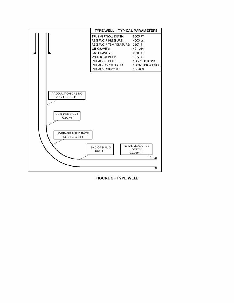
FIGURE 2 - TYPE WELL
TYPE WELL – TYPICAL PARAMETERS
KICK OFF POINT
7250 FT
TOTAL MEASURED
DEPTH
16,000 FT
END OF BUILD
8430 FT
TRUE VERTICAL DEPTH: 8000 FTRESERVOIR PRESSURE: 4000 psiRESERVOIR TEMPERATURE: 210° FOIL GRAVITY: 42° APIGAS GRAVITY: 0.80 SGWATER SALINITY: 1.05 SGINITIAL OIL RATE: 500-2000 BOPDINITIAL GAS OIL RATIO: 1000-2000 SCF/BBLINITIAL WATERCUT: 20-60 %
AVERAGE BUILD RATE
7.6 DEG/100 FT
PRODUCTION CASING
7" 17 LB/FT P110
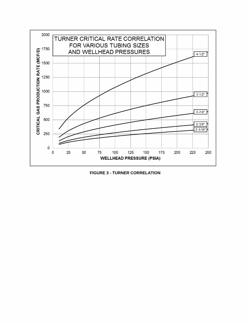
FIGURE 3 - TURNER CORRELATION
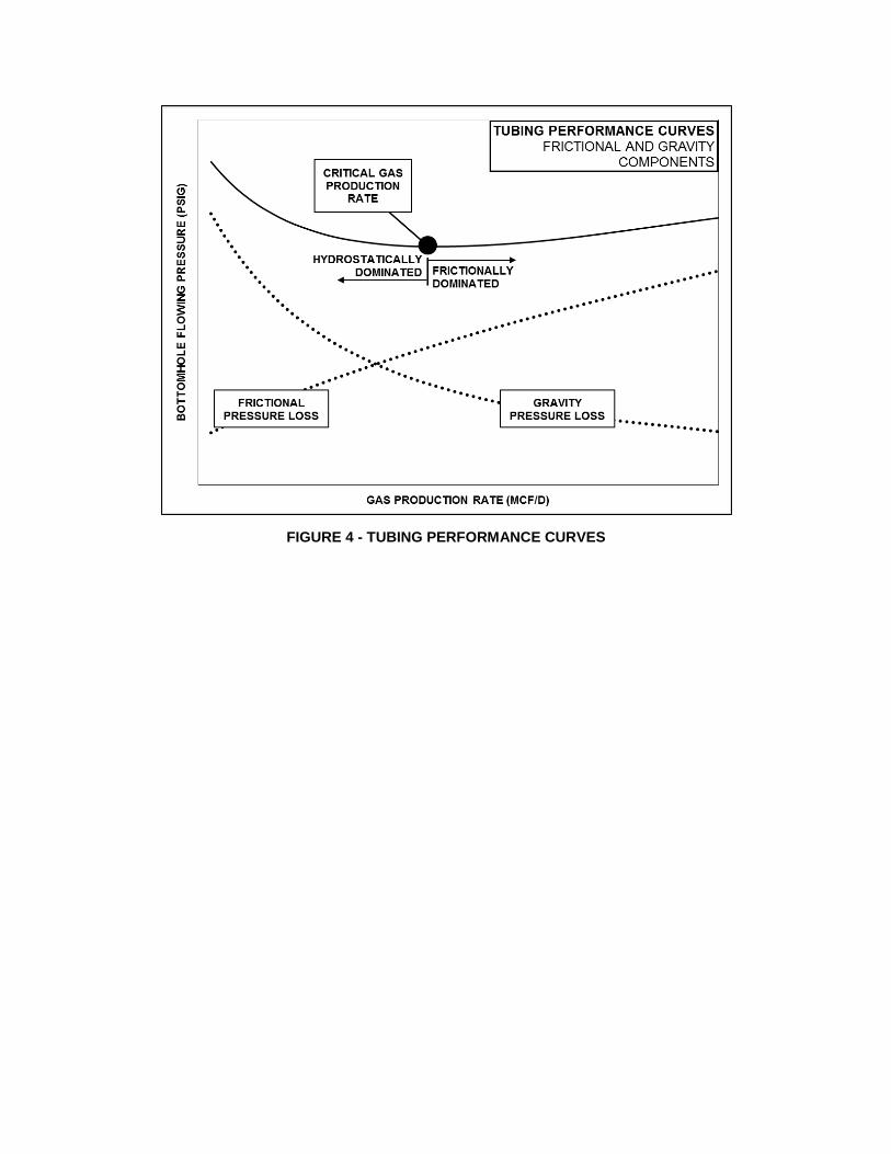
FIGURE 4 - TUBING PERFORMANCE CURVES
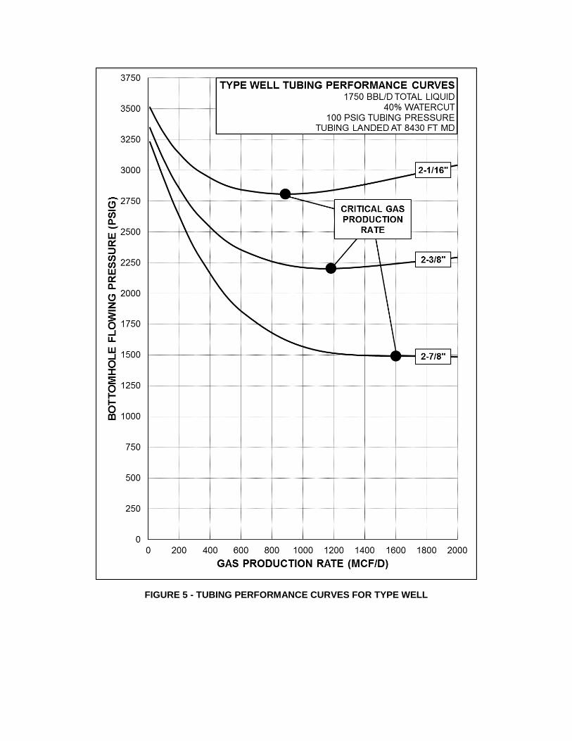
FIGURE 5 - TUBING PERFORMANCE CURVES FOR TYPE WELL
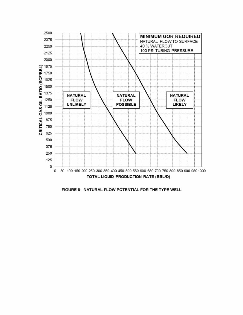
FIGURE 6 - NATURAL FLOW POTENTIAL FOR THE TYPE WELL
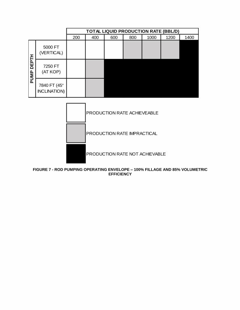
FIGURE 7 - ROD PUMPING OPERATING ENVELOPE – 100% FILLAGE AND 85% VOLUMETRIC EFFICIENCY
200 400 600 800 1000 1200 1400
5000 FT
(VERTICAL)
7250 FT
(AT KOP)
7840 FT (45°
INCLINATION)
PRODUCTION RATE ACHIEVEABLE
PRODUCTION RATE IMPRACTICAL
PRODUCTION RATE NOT ACHIEVABLE
TOTAL LIQUID PRODUCTION RATE (BBL/D)P
UM
P D
EP
TH
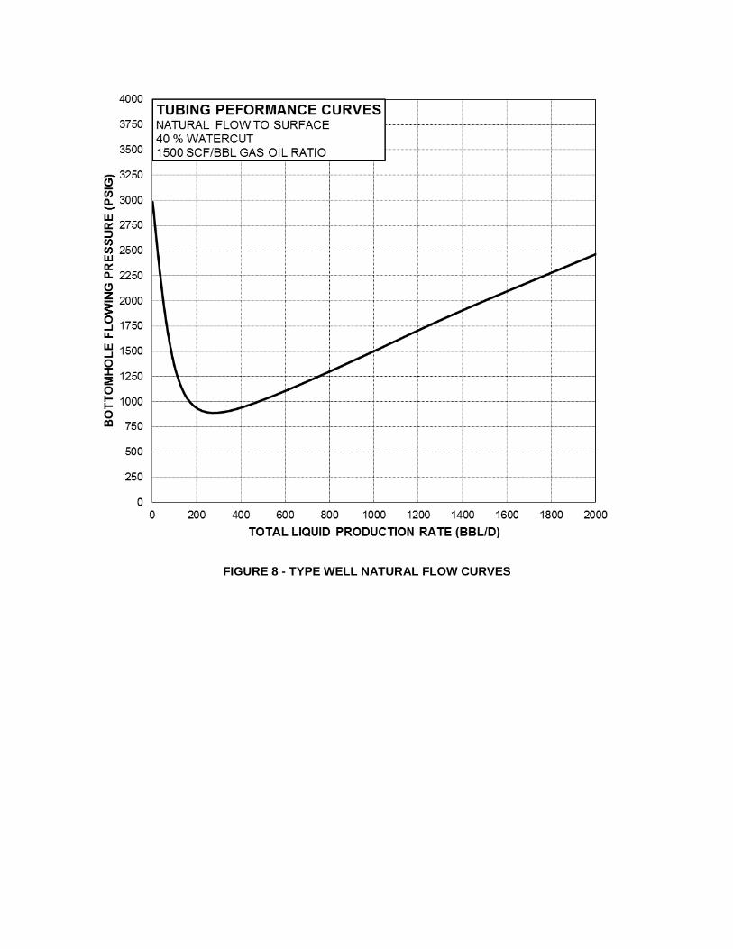
FIGURE 8 - TYPE WELL NATURAL FLOW CURVES
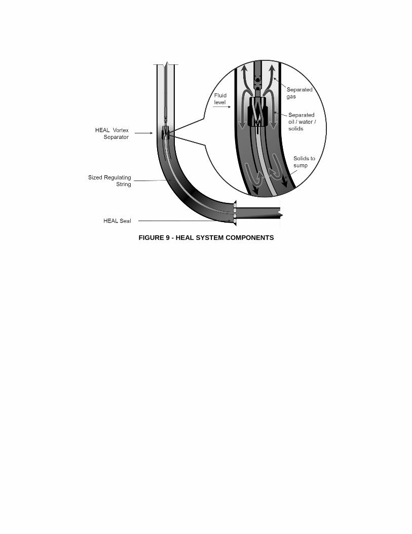
FIGURE 9 - HEAL SYSTEM COMPONENTS
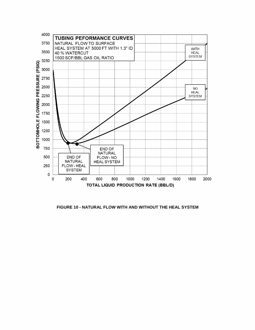
FIGURE 10 - NATURAL FLOW WITH AND WITHOUT THE HEAL SYSTEM
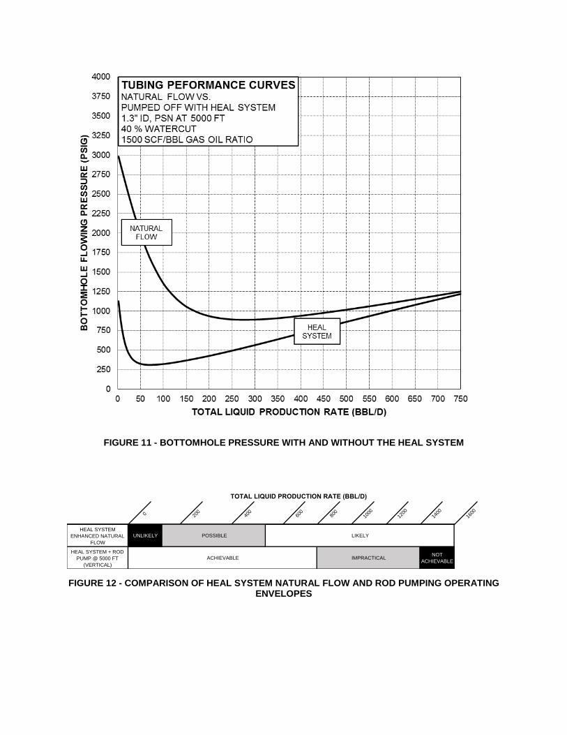
FIGURE 11 - BOTTOMHOLE PRESSURE WITH AND WITHOUT THE HEAL SYSTEM
FIGURE 12 - COMPARISON OF HEAL SYSTEM NATURAL FLOW AND ROD PUMPING OPERATING ENVELOPES
TOTAL LIQUID PRODUCTION RATE (BBL/D)
0 200
400
600
800
1000
1200
1400
1600
HEAL SYSTEM
ENHANCED NATURAL
FLOW
HEAL SYSTEM + ROD
PUMP @ 5000 FT
(VERTICAL)
IMPRACTICAL
LIKELYUNLIKELY POSSIBLE
NOT
ACHIEVABLEACHIEVABLE
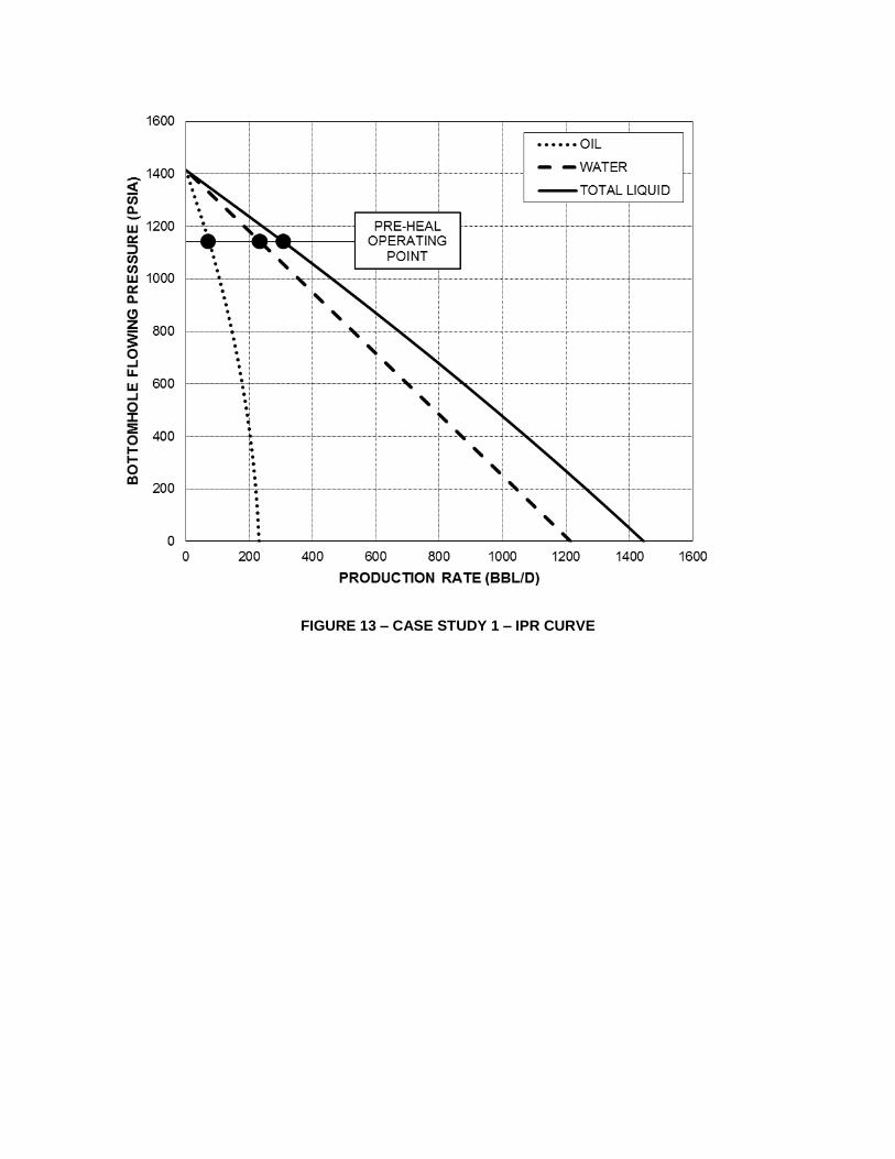
FIGURE 13 – CASE STUDY 1 – IPR CURVE
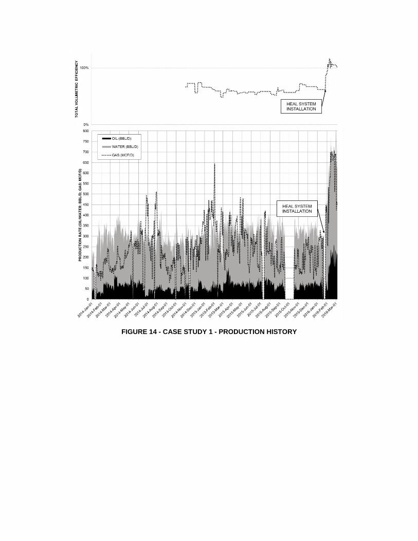
FIGURE 14 - CASE STUDY 1 - PRODUCTION HISTORY
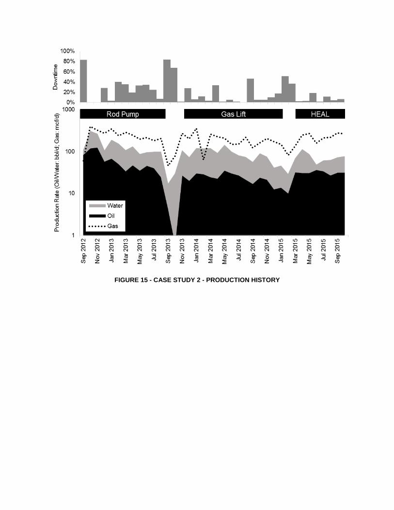
FIGURE 15 - CASE STUDY 2 - PRODUCTION HISTORY
BIBLIOGRAPHY
Artificial Lift R&D Council. n.d. "Artificial Lift Research and Development Council." Accessed March 9, 2016.
http://beta.alrdc.com/recommendations/gas%20well%20deliquification/artificial%20lift%20selection%20--
-%20new%20version.htm.
Hein, Caty. 2012. Halliburton. November 14. Accessed March 9, 2016. http://halliburtonblog.com/artificial-lift-and-
the-5-ps/.
Kimery, D., C. Jensen, and J Saponja. 2016. "Addressing artificial lift predicaments: The challenge is to get more
with less." E&P Magazine 68-69.
Lea, James F., Henry V. Nickens, and M. Wells. 2003. Gas Well Deliquification: Solutions to Gas Well Liquid
Loading Problems. Elsevier.
Petrowiki. 2015. Relative advantages and disadvantages of artificial lift systems. June 30. Accessed March 9, 2016.
http://petrowiki.org/index.php?title=Relative_advantages_and_disadvantages_of_artificial_lift_systems&ol
did=48314.
Schlumberger. 1999. "Gas Lift Design and Technology." Accessed March 9, 2016.
http://igs.nigc.ir/STANDS/BOOK/Gas-Lift-Technology.pdf.
Turner, R. G., M. G. Hubbard, and A. E. Dukler. 1969. "Analysis and prediction of minimum low rate for the
continuous removal of liquids from gas wells." Journal of Petroleum Technology 1475-1482.
ENDNOTES
i Hein, Caty. (Nov, 2012). Artificial Lift Systems and the 5 P’s [Halliburton blog post]. Retrieved from
http://halliburtonblog.com/artificial-lift-and-the-5-ps/. (accessed 9 March 2016).
Schlumberger (1999). Gas lift design and technology. Retrieved from http://igs.nigc.ir/STANDS/BOOK/Gas-Lift-
Technology.pdf (accessed 9 March 2016).
ii Turner, R. G., Hubbard, M. G., and Dukler A. E. (November 1969) Analysis and prediction of minimum low rate
for the continuous removal of liquids from gas wells. Journal of Petroleum Technology, pp. 1475–1482.
iii Lea, James F., Nickens, Henry V., Wells, M. (October 2003). Gas Well Deliquification: Solutions to Gas Well
Liquid Loading Problems. Elsevier. pp. 45-46.
iv Artificial Lift R&D Council (n.d.). Selection of artificial Lift Systems for Deliquifying Gas Wells. Retrieved from
http://beta.alrdc.com/recommendations/gas%20well%20deliquification/artificial%20lift%20selection%20--
-%20new%20version.htm (accessed 9 March 2016).
Hein, Caty. (Nov, 2012). Artificial Lift Systems and the 5 P’s [Halliburton blog post]. Retrieved from
http://halliburtonblog.com/artificial-lift-and-the-5-ps/. (accessed 9 March 2016).
Petrowiki. (2015). Relative advantages and disadvantages of artificial lift systems. Retrieved from
http://petrowiki.org/index.php?title=Relative_advantages_and_disadvantages_of_artificial_lift_systems&ol
did=48314 (accessed 9 March 2016).
Schlumberger (1999). Gas lift design and technology. Retrieved from http://igs.nigc.ir/STANDS/BOOK/Gas-Lift-
Technology.pdf (accessed 9 March 2016).
v Ibid. vi Kimery, D., Jensen, C., Saponja, J. (February 2016). Addressing artificial lift predicaments: The challenge is to get
more with less. E&P Magazine, pp. 68-69. Retrieved from http://www.epmag.com/addressing-
arti%1Fficial-lift-predicaments-836881#p=1. (accessed 9 March 2016)
vii Ibid