Embed Size (px)
Citation preview

DDDeeedddiiiPPPrrroooggg TTTeeeccchhhnnnooolllooogggyyy CCCooo... LLLtttddd wwwwwwwww...dddeeedddiiippprrroooggg...cccooommm
1
DediProg SF Software
User Manual
V5.9
DediProg Technology Co. LTD
4F., No.7, Ln. 143, Xinming Rd., Neihu Dist., Taipei City 114, Taiwan
Email for technical support: [email protected]
Email for Sale information: [email protected]
www.DediProg.com
DDDeeedddiiiPPPrrroooggg TTTeeeccchhhnnnooolllooogggyyy CCCooo... LLLtttddd wwwwwwwww...dddeeedddiiippprrroooggg...cccooommm
2
I. Introduction ..................................................................................................4
II. Software Installation Guide.........................................................................4
A. Operating System Requirement................................................................ 4
B. Installation Procedures ............................................................................. 4
III. Dediprog SF Software Engineering GUI ...................................................8
A. Prepare the Environment .......................................................................... 9
B. Identify the Target SPI Flash.................................................................... 9
C. Tool Bar Description ............................................................................................. 10
D. Edit Window Description ...................................................................................... 12
E. Configuration Window Description....................................................................... 13 1. Batch Operation Option .................................................................................................13 2. Program Configurations.................................................................................................18 3. Engineering Mode..........................................................................................................19 4. Modify Status Register ..................................................................................................20 5. Miscellaneous Settings ..................................................................................................21
F. Supported Devices, Software Version, Firmware Version .................................... 24
IV. Dediprog SF Software Production GUI.....................................................25
A. Main GUI............................................................................................................... 26 i. Search and Select ...........................................................................................................27 ii. Batch Config ..................................................................................................................28 iii. Single Site programming ...............................................................................................29
V. Dediprog Windows Command Line ............................................................29
A. Introduction ........................................................................................................... 30
B. How to Start............................................................................................ 33
C. Basic Usages........................................................................................... 33
D. Basic Switches........................................................................................ 33
E. Optional Switches................................................................................... 34
VI. Stand Alone Mode (SF300 & SF600) ..........................................................36
1. SF300 Standalone Programming:........................................................... 36 A. Project Preparation.........................................................................................................36 B. Stand Alone Mode .........................................................................................................37 C. Standalone Programmer Operations ..............................................................................37 D. SF300 Hardware Description.........................................................................................38
2. SF600 Standalone Programming:........................................................... 39 A. Project preparation.........................................................................................................39 B. Mode switch...................................................................................................................40 C. Standalone programming ...............................................................................................40 D. SF600 Hardware Description.........................................................................................41
VII. Specific Functions.......................................................................................42
Specific functions for SF600: ..................................................................................... 42 1. Dual/Quad IO: ...............................................................................................................42 2. Isolation Free .................................................................................................................43 3. Hold pin status setting....................................................................................................44
VIII. Revision History .........................................................................................45

DDDeeedddiiiPPPrrroooggg TTTeeeccchhhnnnooolllooogggyyy CCCooo... LLLtttddd wwwwwwwww...dddeeedddiiippprrroooggg...cccooommm
3
Important Notice:
This document is provided as a guide line and must not be disclosed without consent of
DediProg. However, no responsibility is assumed for errors that might appear.
DediProg reserves the right to make any changes to the product and/or the specification
at any time without notice. No part of this document may be copied or reproduced in
any form or by any means without prior written consent of DediProg.
DDDeeedddiiiPPPrrroooggg TTTeeeccchhhnnnooolllooogggyyy CCCooo... LLLtttddd wwwwwwwww...dddeeedddiiippprrroooggg...cccooommm
4
I. Introduction
This user manual illustrates the usage of Dediprog SF Software. The device connected
when using this software can be used together with SF100, SF200, SF300, SF600 and
Backup Boot Flash kit. To get more information on our DediProg products and how to
use them, please refer to our products specification, presentation and application notes
in our web site: www.DediProg.com
II. Software Installation Guide
A.Operating System Requirement Windows 7
Windows Server® 2008
Windows Vista®
Windows XP
Support both 32 bit or 64bit OS
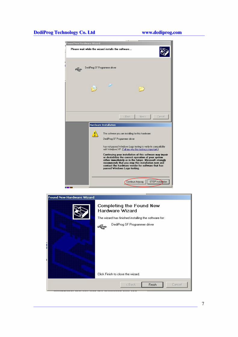
B.Installation Procedures 1. Insert the installation CD or download the installation software from
www.dediprog.com 2. Execute SFx.x.x.msi file and click next until the installation is finished.
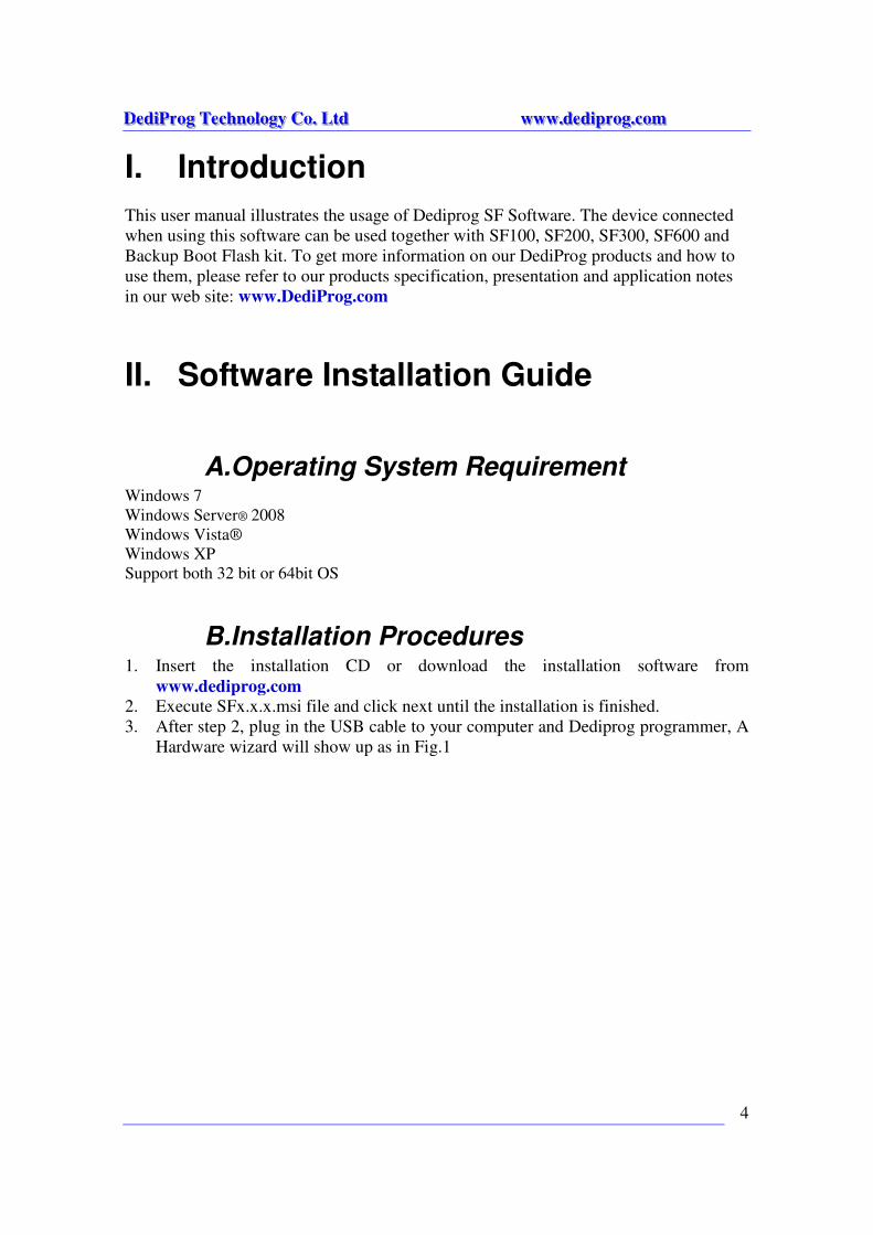
3. After step 2, plug in the USB cable to your computer and Dediprog programmer, A
Hardware wizard will show up as in Fig.1
DDDeeedddiiiPPPrrroooggg TTTeeeccchhhnnnooolllooogggyyy CCCooo... LLLtttddd wwwwwwwww...dddeeedddiiippprrroooggg...cccooommm
5
Fig. 1
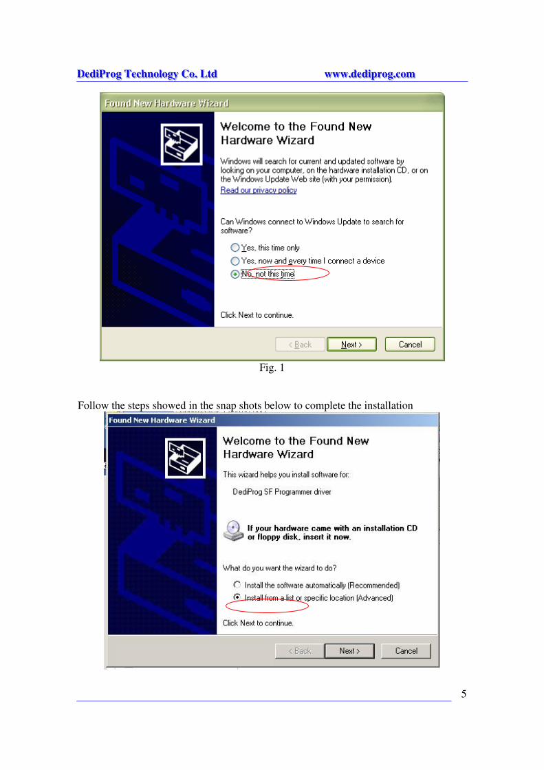
Follow the steps showed in the snap shots below to complete the installation
DDDeeedddiiiPPPrrroooggg TTTeeeccchhhnnnooolllooogggyyy CCCooo... LLLtttddd wwwwwwwww...dddeeedddiiippprrroooggg...cccooommm
6
DDDeeedddiiiPPPrrroooggg TTTeeeccchhhnnnooolllooogggyyy CCCooo... LLLtttddd wwwwwwwww...dddeeedddiiippprrroooggg...cccooommm
7
DDDeeedddiiiPPPrrroooggg TTTeeeccchhhnnnooolllooogggyyy CCCooo... LLLtttddd wwwwwwwww...dddeeedddiiippprrroooggg...cccooommm
8
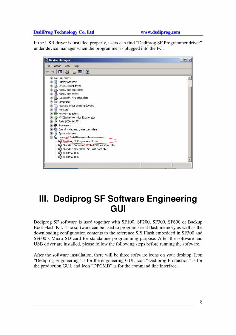
If the USB driver is installed properly, users can find “Dediprog SF Programmer driver”
under device manager when the programmer is plugged into the PC.
III. Dediprog SF Software Engineering GUI
Dediprog SF software is used together with SF100, SF200, SF300, SF600 or Backup
Boot Flash Kit. The software can be used to program serial flash memory as well as the
downloading configuration contents to the reference SPI Flash embedded in SF300 and
SF600’s Micro SD card for standalone programming purpose. After the software and
USB driver are installed, please follow the following steps before running the software.
After the software installation, there will be three software icons on your desktop. Icon
“Dediprog Engineering” is for the engineering GUI, Icon “Dediprog Production” is for
the production GUI, and Icon “DPCMD” is for the command line interface.
DDDeeedddiiiPPPrrroooggg TTTeeeccchhhnnnooolllooogggyyy CCCooo... LLLtttddd wwwwwwwww...dddeeedddiiippprrroooggg...cccooommm
9
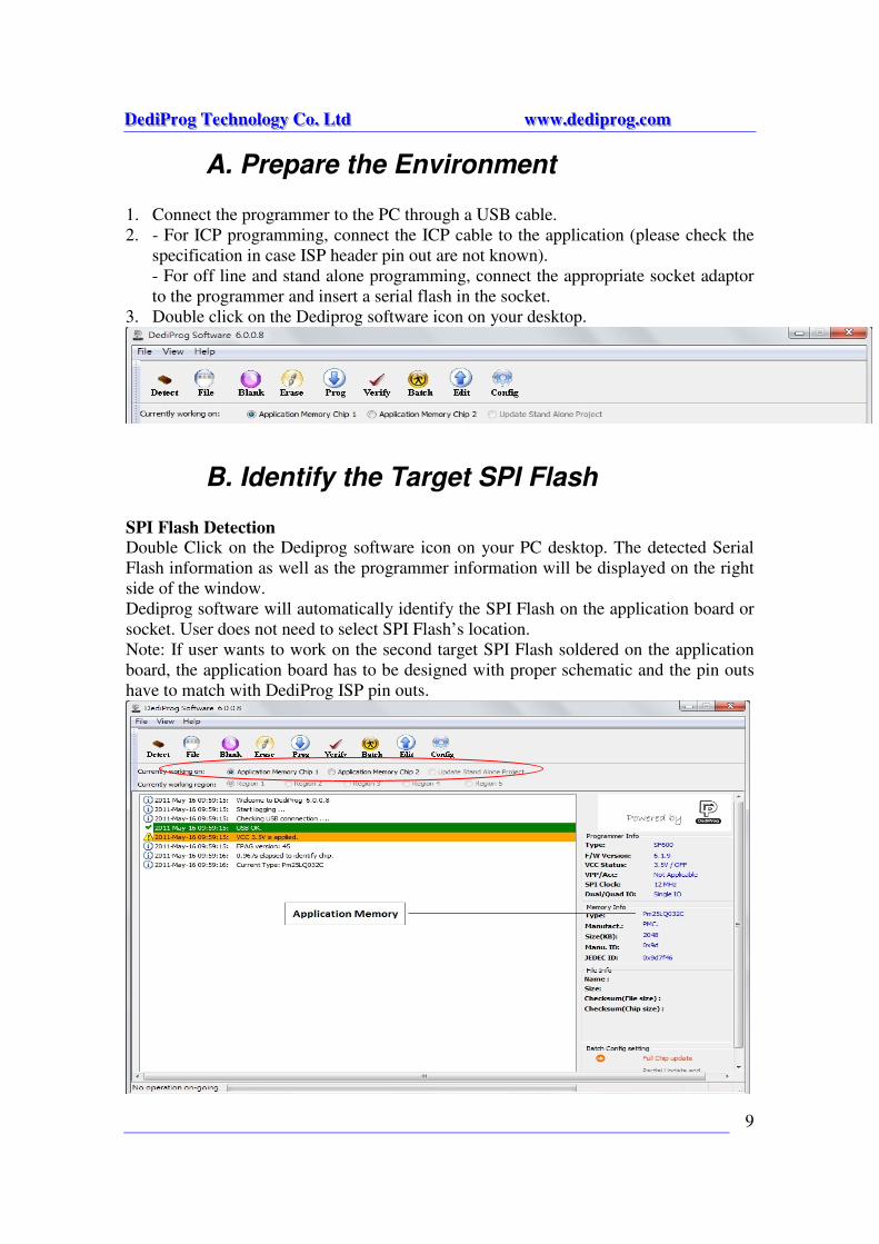
A. Prepare the Environment
1. Connect the programmer to the PC through a USB cable.
2. - For ICP programming, connect the ICP cable to the application (please check the
specification in case ISP header pin out are not known).
- For off line and stand alone programming, connect the appropriate socket adaptor
to the programmer and insert a serial flash in the socket.
3. Double click on the Dediprog software icon on your desktop.
B. Identify the Target SPI Flash
SPI Flash Detection Double Click on the Dediprog software icon on your PC desktop. The detected Serial
Flash information as well as the programmer information will be displayed on the right
side of the window.
Dediprog software will automatically identify the SPI Flash on the application board or
socket. User does not need to select SPI Flash’s location.
Note: If user wants to work on the second target SPI Flash soldered on the application
board, the application board has to be designed with proper schematic and the pin outs
have to match with DediProg ISP pin outs.
DDDeeedddiiiPPPrrroooggg TTTeeeccchhhnnnooolllooogggyyy CCCooo... LLLtttddd wwwwwwwww...dddeeedddiiippprrroooggg...cccooommm
10
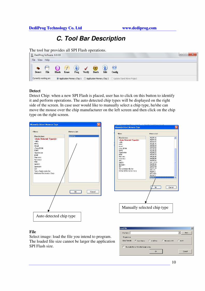
C. Tool Bar Description
The tool bar provides all SPI Flash operations.
Detect
Detect Chip: when a new SPI Flash is placed, user has to click on this button to identify
it and perform operations. The auto detected chip types will be displayed on the right
side of the screen. In case user would like to manually select a chip type, he/she can
move the mouse over the chip manufacturer on the left screen and then click on the chip
type on the right screen.
File
Select image: load the file you intend to program.
The loaded file size cannot be larger the application
SPI Flash size.
Auto detected chip type
Manually selected chip type
DDDeeedddiiiPPPrrroooggg TTTeeeccchhhnnnooolllooogggyyy CCCooo... LLLtttddd wwwwwwwww...dddeeedddiiippprrroooggg...cccooommm
11
Blank
Blank check: check if the target serial flash is Blank (All Erased)
Erase
Erase SPI Flash: Erase the full content in a Serial Flash. After “Erase” the target serial
flash shall be blank.
Prog
Program: Program the selected image into the Serial Flash
Verify
Verify the checksum value of the selected image and the programmed Serial Flash
content
Batch
Batch operation: The programmer will perform a pre-configured set of operations such
as (reload file + erase + program + verify) all together in one click. The configuration
can be set by clicking on the “Config” button. The configuration will not be changed
until it is re-configured.
Edit
When click on Edit, the programmer will by default display the selected file content.
User can click on “read” to read and display the chip contents. See “Edit window
description” for more details.
Config
This allows users to configure advanced settings.
See “advanced settings window description” for more details
DDDeeedddiiiPPPrrroooggg TTTeeeccchhhnnnooolllooogggyyy CCCooo... LLLtttddd wwwwwwwww...dddeeedddiiippprrroooggg...cccooommm
12
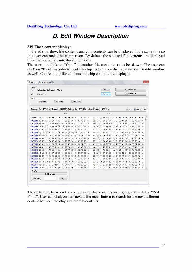
D. Edit Window Description
SPI Flash content display:
In the edit window, file contents and chip contents can be displayed in the same time so
that user can make the comparison. By default the selected file contents are displayed
once the user enters into the edit window.
The user can click on “Open” if another file contents are to be shown. The user can
click on “Read” in order to read the chip contents are display them on the edit window
as well. Checksum of file contents and chip contents are displayed.
The difference between file contents and chip contents are highlighted with the “Red
Fonts”. User can click on the “next difference” button to search for the next different
content between the chip and the file contents.
DDDeeedddiiiPPPrrroooggg TTTeeeccchhhnnnooolllooogggyyy CCCooo... LLLtttddd wwwwwwwww...dddeeedddiiippprrroooggg...cccooommm
13
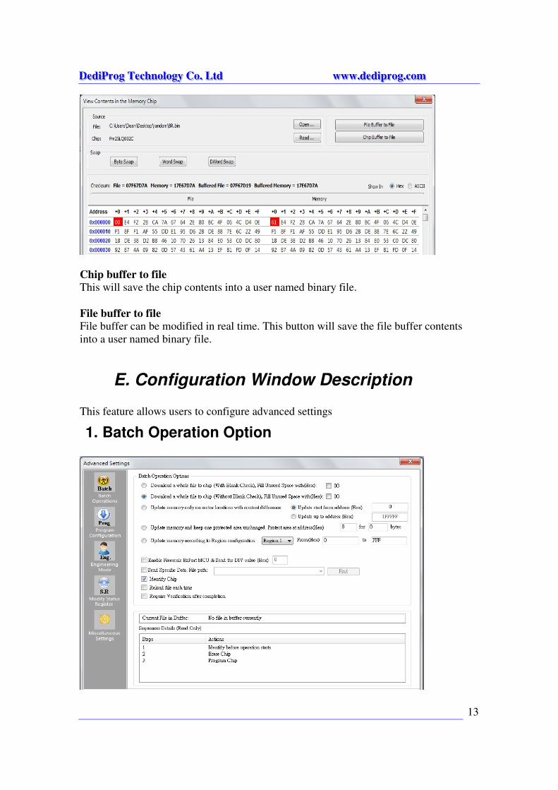
Chip buffer to file
This will save the chip contents into a user named binary file.
File buffer to file
File buffer can be modified in real time. This button will save the file buffer contents
into a user named binary file.
E. Configuration Window Description
This feature allows users to configure advanced settings
1. Batch Operation Option

DDDeeedddiiiPPPrrroooggg TTTeeeccchhhnnnooolllooogggyyy CCCooo... LLLtttddd wwwwwwwww...dddeeedddiiippprrroooggg...cccooommm
14
1. Update a Whole file with Blank check
When the user clicks on Batch button, the following operations will be
automatically executed:
1) Read the memory content
2) Blank check (check if Chip is erased)
3) Erase the whole memory if not blank
4) Program the whole memory with the file 5) Verify if the memory content is identical with the programmed file.
2. Update a Whole file without Blank check
When the user clicks on Batch button, the following operations will be
automatically executed:
1) Erase the whole memory
2) Program the whole memory with the file
3) Verify if the memory content is identical with the programmed file.
3. Update memory only on sector locations with contents difference or
Smart update
User can select the sector locations to have the file programmed.
- Update start from address (Hex): To program a whole file starting
from address 0 of a chip.
- Update up to address (Hex): To program a whole file, ending at the
last address of a chip. The default ending address will automatically
calculated by the software according to memory size.
When the user clicks on Batch button, the following operations will be
automatically executed:
1) Read the memory content
2) Compare the memory content from the given address with the file at the
64KB sector base
3) Erase only the 64KB sectors with some differences
4) Program only the erased sectors with the file data of the corresponding
address
5) Verify the data on the updated 64KB sectors
Smart Update can be used in the following cases:
- A small file can be programmed or updated at a given address without any
change on the rest of the memory (local update).
- A file with only minor change compare to the memory content can be quickly
updated. The sectors without difference are kept unchanged.
DDDeeedddiiiPPPrrroooggg TTTeeeccchhhnnnooolllooogggyyy CCCooo... LLLtttddd wwwwwwwww...dddeeedddiiippprrroooggg...cccooommm
15
Remark: the file data which are identical with the target memory but with an address shift
(after compilation) will be interpreted as different and will not benefit of the Smart update
advantages.
4. Update memory and keep one protected area unchanged
When the user clicks on Batch button, the following operations will be
automatically executed:
1) Read the memory content from the given address for the given length
2) Insert the read memory contents into the file buffer
3) Erase the whole chip
4) Program the whole chip with the updated file in step 2
5) Verify the programmed data
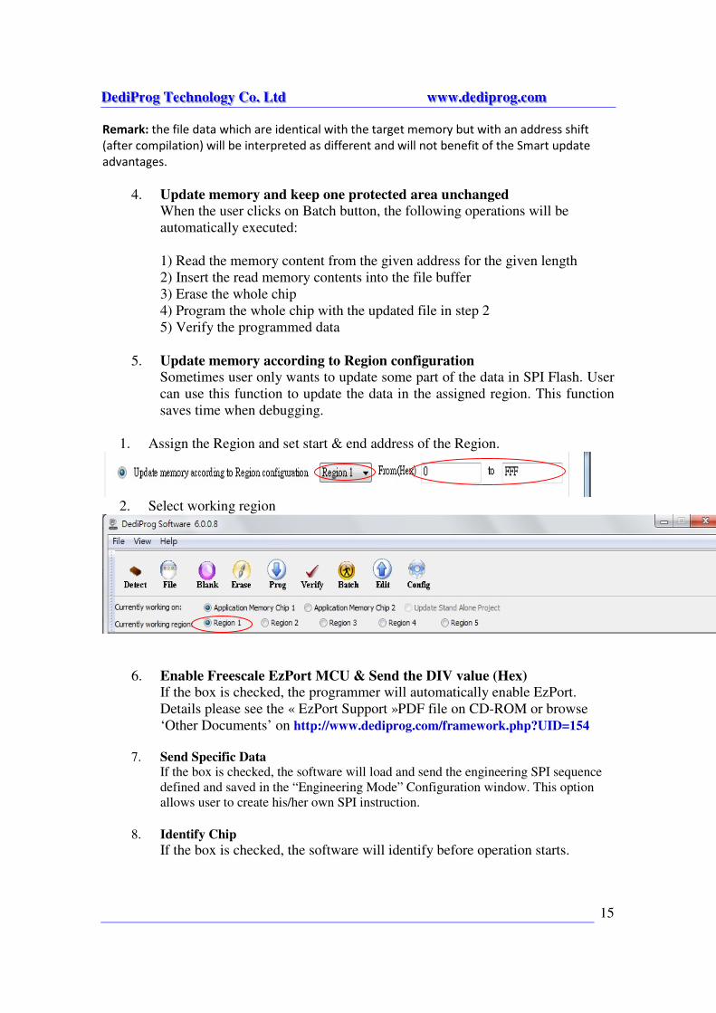
5. Update memory according to Region configuration
Sometimes user only wants to update some part of the data in SPI Flash. User
can use this function to update the data in the assigned region. This function
saves time when debugging.
1. Assign the Region and set start & end address of the Region.
2. Select working region
6. Enable Freescale EzPort MCU & Send the DIV value (Hex)
If the box is checked, the programmer will automatically enable EzPort.
Details please see the « EzPort Support »PDF file on CD-ROM or browse
‘Other Documents’ on http://www.dediprog.com/framework.php?UID=154
7. Send Specific Data If the box is checked, the software will load and send the engineering SPI sequence
defined and saved in the “Engineering Mode” Configuration window. This option
allows user to create his/her own SPI instruction.
8. Identify Chip
If the box is checked, the software will identify before operation starts.
DDDeeedddiiiPPPrrroooggg TTTeeeccchhhnnnooolllooogggyyy CCCooo... LLLtttddd wwwwwwwww...dddeeedddiiippprrroooggg...cccooommm
16
9. Reload file each time
If the box is checked, the software will load the same file from the source destination
each time before the batch operations (refresh). This option is helpful when another
software update the file in parallel (like compiler).
10. Require Verification after completion
If this box is checked, the software will verify the contents between the source file
and the programmed Serial Flash contents after the batch operations.
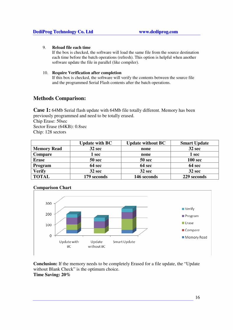
Methods Comparison:
Case 1: 64Mb Serial flash update with 64Mb file totally different. Memory has been
previously programmed and need to be totally erased.
Chip Erase: 50sec
Sector Erase (64KB): 0.8sec
Chip: 128 sectors
Update with BC Update without BC Smart Update
Memory Read 32 sec none 32 sec
Compare 1 sec none 1 sec
Erase 50 sec 50 sec 100 sec
Program 64 sec 64 sec 64 sec
Verify 32 sec 32 sec 32 sec
TOTAL 179 seconds 146 seconds 229 seconds
Comparison Chart
Conclusion: If the memory needs to be completely Erased for a file update, the “Update
without Blank Check” is the optimum choice.
Time Saving: 20%
DDDeeedddiiiPPPrrroooggg TTTeeeccchhhnnnooolllooogggyyy CCCooo... LLLtttddd wwwwwwwww...dddeeedddiiippprrroooggg...cccooommm
17
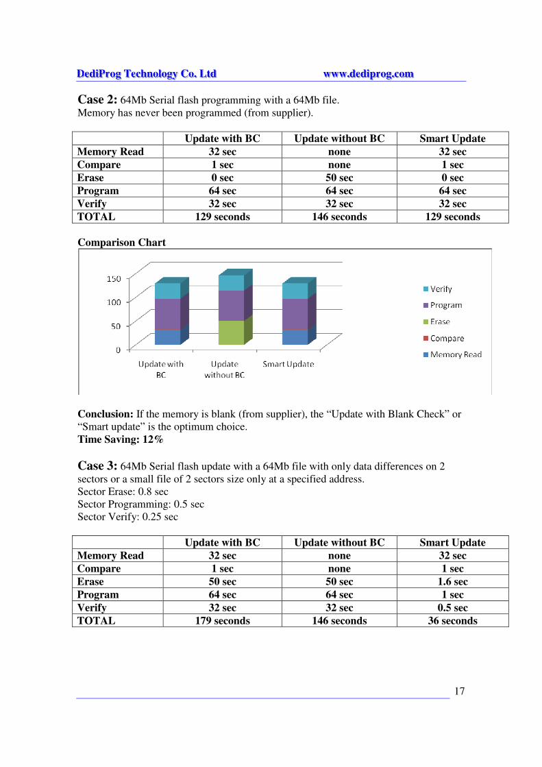
Case 2: 64Mb Serial flash programming with a 64Mb file.
Memory has never been programmed (from supplier).
Update with BC Update without BC Smart Update
Memory Read 32 sec none 32 sec
Compare 1 sec none 1 sec
Erase 0 sec 50 sec 0 sec
Program 64 sec 64 sec 64 sec
Verify 32 sec 32 sec 32 sec
TOTAL 129 seconds 146 seconds 129 seconds
Comparison Chart
Conclusion: If the memory is blank (from supplier), the “Update with Blank Check” or
“Smart update” is the optimum choice.
Time Saving: 12%
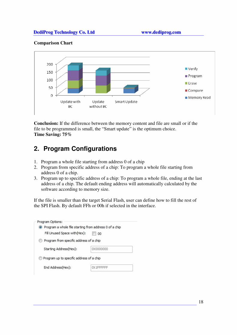
Case 3: 64Mb Serial flash update with a 64Mb file with only data differences on 2
sectors or a small file of 2 sectors size only at a specified address.
Sector Erase: 0.8 sec
Sector Programming: 0.5 sec
Sector Verify: 0.25 sec
Update with BC Update without BC Smart Update
Memory Read 32 sec none 32 sec
Compare 1 sec none 1 sec
Erase 50 sec 50 sec 1.6 sec
Program 64 sec 64 sec 1 sec
Verify 32 sec 32 sec 0.5 sec
TOTAL 179 seconds 146 seconds 36 seconds
DDDeeedddiiiPPPrrroooggg TTTeeeccchhhnnnooolllooogggyyy CCCooo... LLLtttddd wwwwwwwww...dddeeedddiiippprrroooggg...cccooommm
18
Comparison Chart
Conclusion: If the difference between the memory content and file are small or if the
file to be programmed is small, the “Smart update” is the optimum choice.
Time Saving: 75%
2. Program Configurations 1. Program a whole file starting from address 0 of a chip
2. Program from specific address of a chip: To program a whole file starting from
address 0 of a chip.
3. Program up to specific address of a chip: To program a whole file, ending at the last
address of a chip. The default ending address will automatically calculated by the
software according to memory size.
If the file is smaller than the target Serial Flash, user can define how to fill the rest of
the SPI Flash. By default FFh or 00h if selected in the interface.
DDDeeedddiiiPPPrrroooggg TTTeeeccchhhnnnooolllooogggyyy CCCooo... LLLtttddd wwwwwwwww...dddeeedddiiippprrroooggg...cccooommm
19
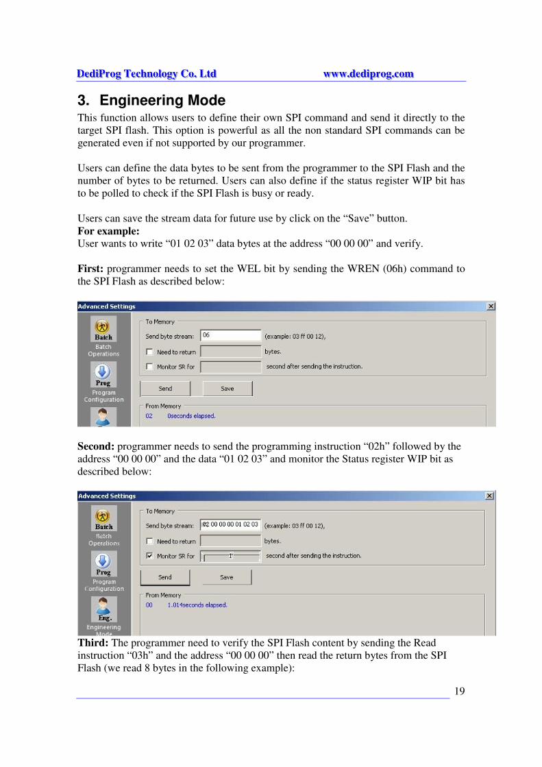
3. Engineering Mode This function allows users to define their own SPI command and send it directly to the
target SPI flash. This option is powerful as all the non standard SPI commands can be
generated even if not supported by our programmer.
Users can define the data bytes to be sent from the programmer to the SPI Flash and the
number of bytes to be returned. Users can also define if the status register WIP bit has
to be polled to check if the SPI Flash is busy or ready.
Users can save the stream data for future use by click on the “Save” button.
For example:
User wants to write “01 02 03” data bytes at the address “00 00 00” and verify.
First: programmer needs to set the WEL bit by sending the WREN (06h) command to
the SPI Flash as described below:
Second: programmer needs to send the programming instruction “02h” followed by the
address “00 00 00” and the data “01 02 03” and monitor the Status register WIP bit as
described below:
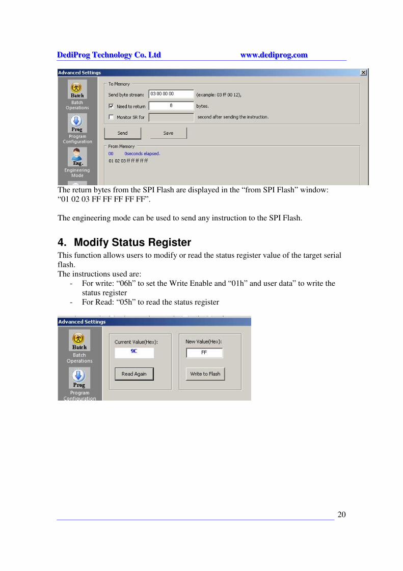
Third: The programmer need to verify the SPI Flash content by sending the Read
instruction “03h” and the address “00 00 00” then read the return bytes from the SPI
Flash (we read 8 bytes in the following example):
DDDeeedddiiiPPPrrroooggg TTTeeeccchhhnnnooolllooogggyyy CCCooo... LLLtttddd wwwwwwwww...dddeeedddiiippprrroooggg...cccooommm
20
The return bytes from the SPI Flash are displayed in the “from SPI Flash” window:
“01 02 03 FF FF FF FF FF”.
The engineering mode can be used to send any instruction to the SPI Flash.
4. Modify Status Register This function allows users to modify or read the status register value of the target serial
flash.
The instructions used are:
- For write: “06h” to set the Write Enable and “01h” and user data” to write the
status register
- For Read: “05h” to read the status register
DDDeeedddiiiPPPrrroooggg TTTeeeccchhhnnnooolllooogggyyy CCCooo... LLLtttddd wwwwwwwww...dddeeedddiiippprrroooggg...cccooommm
21
a) Vpp
b) Vcc
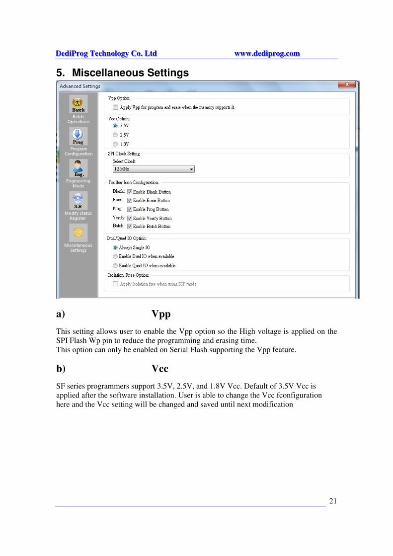
5. Miscellaneous Settings
This setting allows user to enable the Vpp option so the High voltage is applied on the
SPI Flash Wp pin to reduce the programming and erasing time.
This option can only be enabled on Serial Flash supporting the Vpp feature.
SF series programmers support 3.5V, 2.5V, and 1.8V Vcc. Default of 3.5V Vcc is
applied after the software installation. User is able to change the Vcc fconfiguration
here and the Vcc setting will be changed and saved until next modification
DDDeeedddiiiPPPrrroooggg TTTeeeccchhhnnnooolllooogggyyy CCCooo... LLLtttddd wwwwwwwww...dddeeedddiiippprrroooggg...cccooommm
22
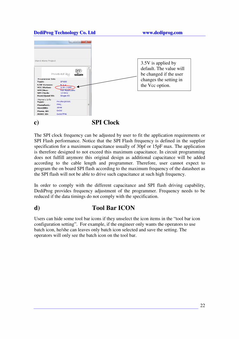
c) SPI Clock
Setting
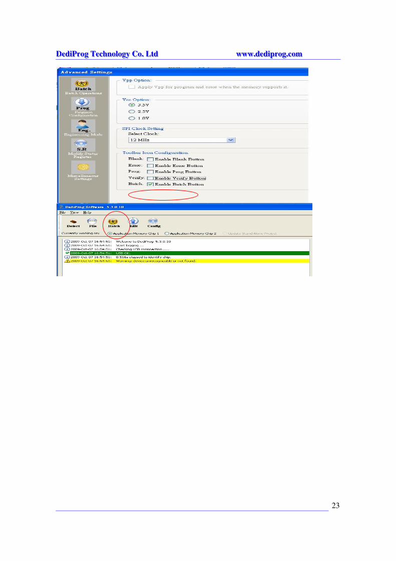
d) Tool Bar ICON
The SPI clock frequency can be adjusted by user to fit the application requirements or
SPI Flash performance. Notice that the SPI Flash frequency is defined in the supplier
specification for a maximum capacitance usually of 30pf or 15pF max. The application
is therefore designed to not exceed this maximum capacitance. In circuit programming
does not fulfill anymore this original design as additional capacitance will be added
according to the cable length and programmer. Therefore, user cannot expect to
program the on board SPI flash according to the maximum frequency of the datasheet as
the SPI flash will not be able to drive such capacitance at such high frequency.
In order to comply with the different capacitance and SPI flash driving capability,
DediProg provides frequency adjustment of the programmer. Frequency needs to be
reduced if the data timings do not comply with the specification.
Users can hide some tool bar icons if they unselect the icon items in the “tool bar icon
configuration setting”. For example, if the engineer only wants the operators to use
batch icon, he/she can leaves only batch icon selected and save the setting. The
operators will only see the batch icon on the tool bar.
3.5V is applied by
default. The value will
be changed if the user
changes the setting in
the Vcc option.
DDDeeedddiiiPPPrrroooggg TTTeeeccchhhnnnooolllooogggyyy CCCooo... LLLtttddd wwwwwwwww...dddeeedddiiippprrroooggg...cccooommm
23
DDDeeedddiiiPPPrrroooggg TTTeeeccchhhnnnooolllooogggyyy CCCooo... LLLtttddd wwwwwwwww...dddeeedddiiippprrroooggg...cccooommm
24
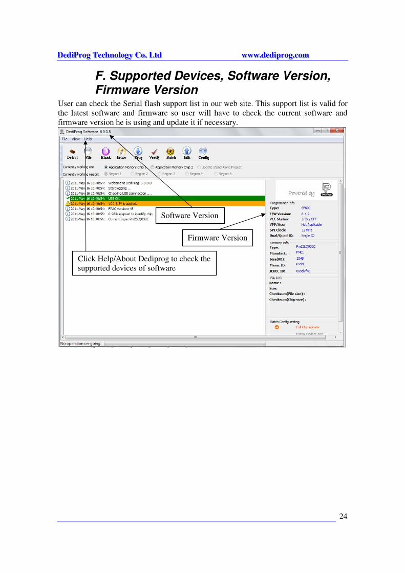
F. Supported Devices, Software Version, Firmware Version
User can check the Serial flash support list in our web site. This support list is valid for
the latest software and firmware so user will have to check the current software and
firmware version he is using and update it if necessary.
Software Version
Firmware Version
Click Help/About Dediprog to check the
supported devices of software
DDDeeedddiiiPPPrrroooggg TTTeeeccchhhnnnooolllooogggyyy CCCooo... LLLtttddd wwwwwwwww...dddeeedddiiippprrroooggg...cccooommm
25
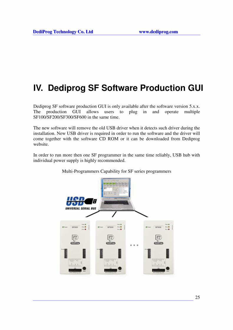
IV. Dediprog SF Software Production GUI
Dediprog SF software production GUI is only available after the software version 5.x.x.
The production GUI allows users to plug in and operate multiple
SF100/SF200/SF300/SF600 in the same time.
The new software will remove the old USB driver when it detects such driver during the
installation. New USB driver is required in order to run the software and the driver will
come together with the software CD ROM or it can be downloaded from Dediprog
website.
In order to run more then one SF programmer in the same time reliably, USB hub with
individual power supply is highly recommended.
Multi-Programmers Capability for SF series programmers
DDDeeedddiiiPPPrrroooggg TTTeeeccchhhnnnooolllooogggyyy CCCooo... LLLtttddd wwwwwwwww...dddeeedddiiippprrroooggg...cccooommm
26
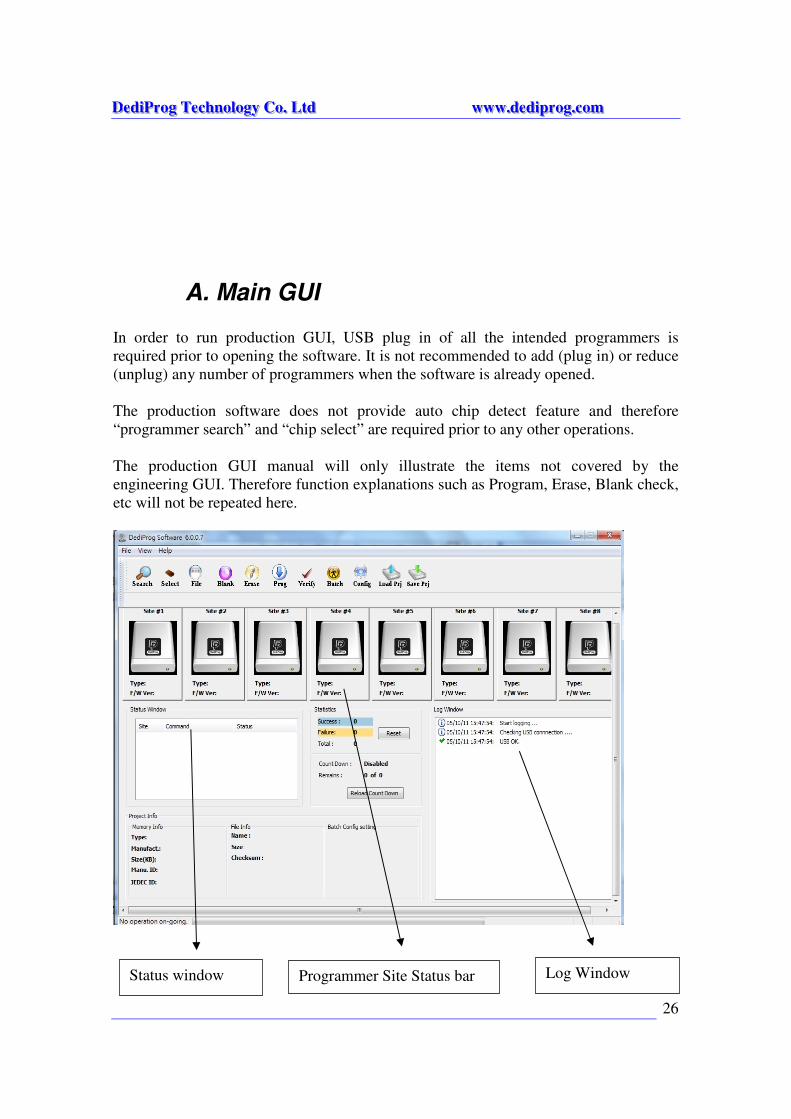
A. Main GUI
In order to run production GUI, USB plug in of all the intended programmers is
required prior to opening the software. It is not recommended to add (plug in) or reduce
(unplug) any number of programmers when the software is already opened.
The production software does not provide auto chip detect feature and therefore
“programmer search” and “chip select” are required prior to any other operations.
The production GUI manual will only illustrate the items not covered by the
engineering GUI. Therefore function explanations such as Program, Erase, Blank check,
etc will not be repeated here.
Status window Programmer Site Status bar Log Window
DDDeeedddiiiPPPrrroooggg TTTeeeccchhhnnnooolllooogggyyy CCCooo... LLLtttddd wwwwwwwww...dddeeedddiiippprrroooggg...cccooommm
27
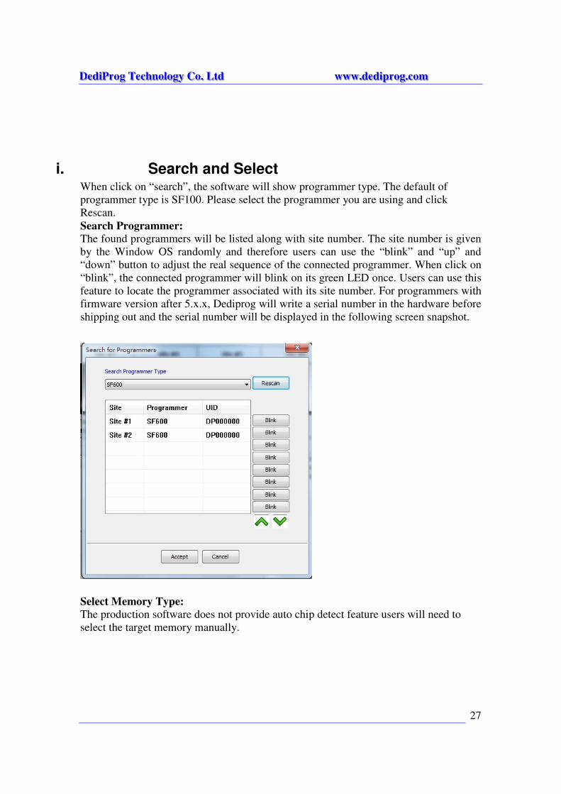
i. Search and Select When click on “search”, the software will show programmer type. The default of
programmer type is SF100. Please select the programmer you are using and click
Rescan.
Search Programmer:
The found programmers will be listed along with site number. The site number is given
by the Window OS randomly and therefore users can use the “blink” and “up” and
“down” button to adjust the real sequence of the connected programmer. When click on
“blink”, the connected programmer will blink on its green LED once. Users can use this
feature to locate the programmer associated with its site number. For programmers with
firmware version after 5.x.x, Dediprog will write a serial number in the hardware before
shipping out and the serial number will be displayed in the following screen snapshot.
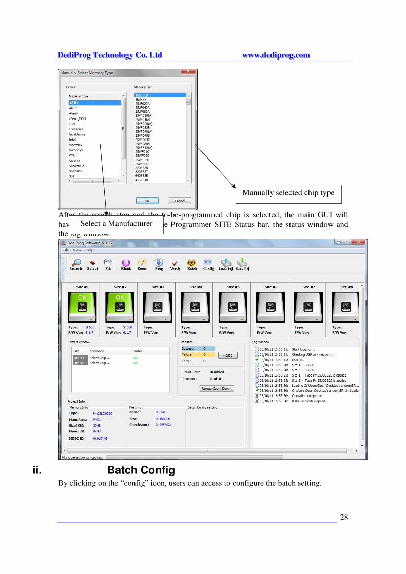
Select Memory Type:
The production software does not provide auto chip detect feature users will need to
select the target memory manually.
DDDeeedddiiiPPPrrroooggg TTTeeeccchhhnnnooolllooogggyyy CCCooo... LLLtttddd wwwwwwwww...dddeeedddiiippprrroooggg...cccooommm
28
After the search step and the to-be-programmed chip is selected, the main GUI will
have updated information on the Programmer SITE Status bar, the status window and
the log window.
ii. Batch Config By clicking on the “config” icon, users can access to configure the batch setting.
Select a Manufacturer
Manually selected chip type
DDDeeedddiiiPPPrrroooggg TTTeeeccchhhnnnooolllooogggyyy CCCooo... LLLtttddd wwwwwwwww...dddeeedddiiippprrroooggg...cccooommm
29
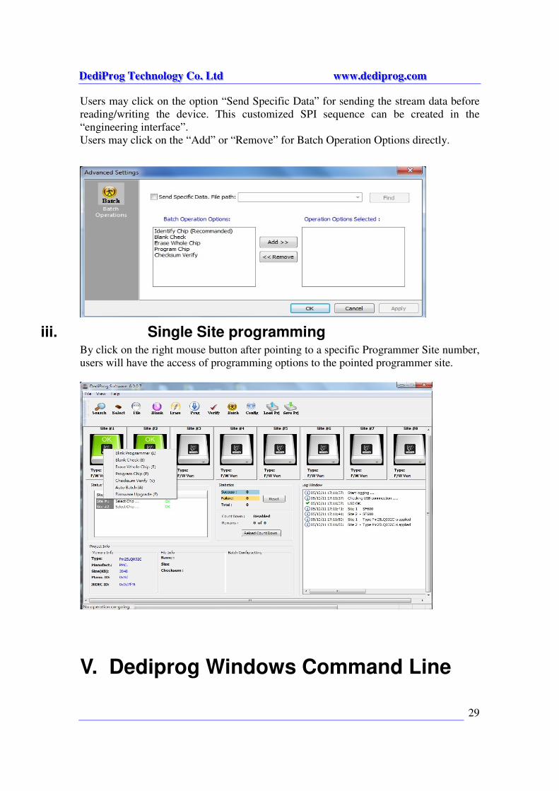
Users may click on the option “Send Specific Data” for sending the stream data before
reading/writing the device. This customized SPI sequence can be created in the
“engineering interface”.
Users may click on the “Add” or “Remove” for Batch Operation Options directly.
iii. Single Site programming By click on the right mouse button after pointing to a specific Programmer Site number,
users will have the access of programming options to the pointed programmer site.
V. Dediprog Windows Command Line
DDDeeedddiiiPPPrrroooggg TTTeeeccchhhnnnooolllooogggyyy CCCooo... LLLtttddd wwwwwwwww...dddeeedddiiippprrroooggg...cccooommm
30
A. Introduction
The window command line has been designed to control our programmer from another
software. This feature will be convenient to synchronize the two software in
development (For example: program the memory automatically after the code has been
compiled) or in production (for example: Program automatically the Serial Flash via the
ICT tester after the hardware has been checked).
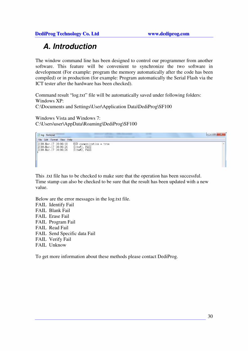
Command result “log.txt” file will be automatically saved under following folders:
Windows XP:
C:\Documents and Settings\User\Application Data\DediProg\SF100
Windows Vista and Windows 7:
C:\Users\user\AppData\Roaming\DediProg\SF100
This .txt file has to be checked to make sure that the operation has been successful.
Time stamp can also be checked to be sure that the result has been updated with a new
value.
Below are the error messages in the log.txt file.
FAIL Identify Fail
FAIL Blank Fail
FAIL Erase Fail
FAIL Program Fail
FAIL Read Fail
FAIL Send Specific data Fail
FAIL Verify Fail
FAIL Unknow
To get more information about these methods please contact DediProg.
DDDeeedddiiiPPPrrroooggg TTTeeeccchhhnnnooolllooogggyyy CCCooo... LLLtttddd wwwwwwwww...dddeeedddiiippprrroooggg...cccooommm
31
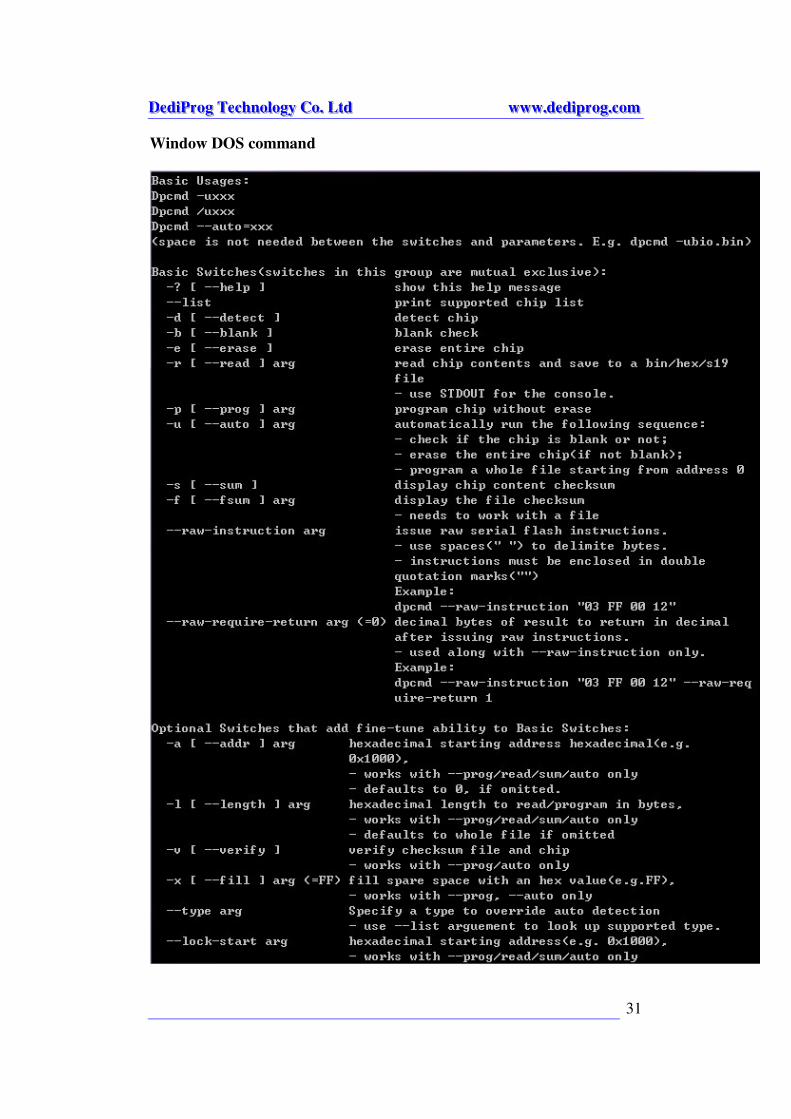
Window DOS command
DDDeeedddiiiPPPrrroooggg TTTeeeccchhhnnnooolllooogggyyy CCCooo... LLLtttddd wwwwwwwww...dddeeedddiiippprrroooggg...cccooommm
32
DDDeeedddiiiPPPrrroooggg TTTeeeccchhhnnnooolllooogggyyy CCCooo... LLLtttddd wwwwwwwww...dddeeedddiiippprrroooggg...cccooommm
33
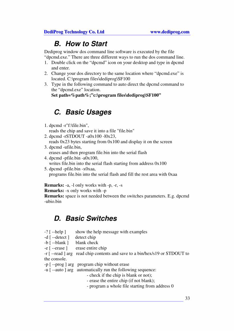
B. How to Start Dediprog window dos command line software is executed by the file
“dpcmd.exe.” There are three different ways to run the dos command line.
1. Double click on the “dpcmd” icon on your desktop and type in dpcmd
and enter.
2. Change your dos directory to the same location where “dpcmd.exe” is
located. C:\program files\dediprog\SF100
3. Type in the following command to auto direct the dpcmd command to
the “dpcmd.exe” location.
Set path=%path%;”c:\program files\dediprog\SF100”
C. Basic Usages
1. dpcmd -r"f:\file.bin",
reads the chip and save it into a file "file.bin"
2. dpcmd -rSTDOUT -a0x100 -l0x23,
reads 0x23 bytes starting from 0x100 and display it on the screen
3. dpcmd -ufile.bin,
erases and then program file.bin into the serial flash
4. dpcmd -pfile.bin -a0x100,
writes file.bin into the serial flash starting from address 0x100
5. dpcmd -pfile.bin -x0xaa,
programs file.bin into the serial flash and fill the rest area with 0xaa
Remarks: -a, -l only works with -p, -r, -s
Remarks: -x only works with -p
Remarks: space is not needed between the switches parameters. E.g. dpcmd
-ubio.bin
D. Basic Switches
-? [ --help ] show the help message with examples
-d [ --detect ] detect chip
-b [ --blank ] blank check
-e [ --erase ] erase entire chip
-r [ --read ] arg read chip contents and save to a bin/hex/s19 or STDOUT to
the console.
-p [ --prog ] arg program chip without erase
-u [ --auto ] arg automatically run the following sequence:
- check if the chip is blank or not);
- erase the entire chip (if not blank);
- program a whole file starting from address 0
DDDeeedddiiiPPPrrroooggg TTTeeeccchhhnnnooolllooogggyyy CCCooo... LLLtttddd wwwwwwwww...dddeeedddiiippprrroooggg...cccooommm
34
-s [ --sum ] display chip content checksum
-f [ --fsum ] arg display the file checksum(needs to work with a file)
--raw-instruction issue raw serial flash instructions
Example:
dpcmd –raw-instruction “03 FF 00 12”
--raw-require-return arg <=0> decimal bytes of result to return in
decimal after issuing raw instructions
- use along with –raw-instruction only
Example:
dpcmd –raw-instruction “03 FF 00
12” –raw-require-return 1
--list print the supported chip list
E. Optional Switches
(specify the following switches to change default values):
-i [ --silent] suppress the display of real-time timer counting, – used
when integrating with 3rd
-party tool(e.g. IDE)
-v[ --verify] arg verify the checksum of the file and the target chip
-x[ --fill ] arg fill the rest of the chip with an hex value, - works with --
prog only
-a[ --addr ] arg starting address(e.g. 0x1000), - works with --prog, --read
and --sum only
- defaults to 0, if omitted.
--type arg specify a type to override auto detection
- use --list argument to look up the supported type
--lock-start arg hexadecimal starting address(e.g. 0x1000),
- works with --prog/read/sum/auto only
- defaults to 0, if omitted.
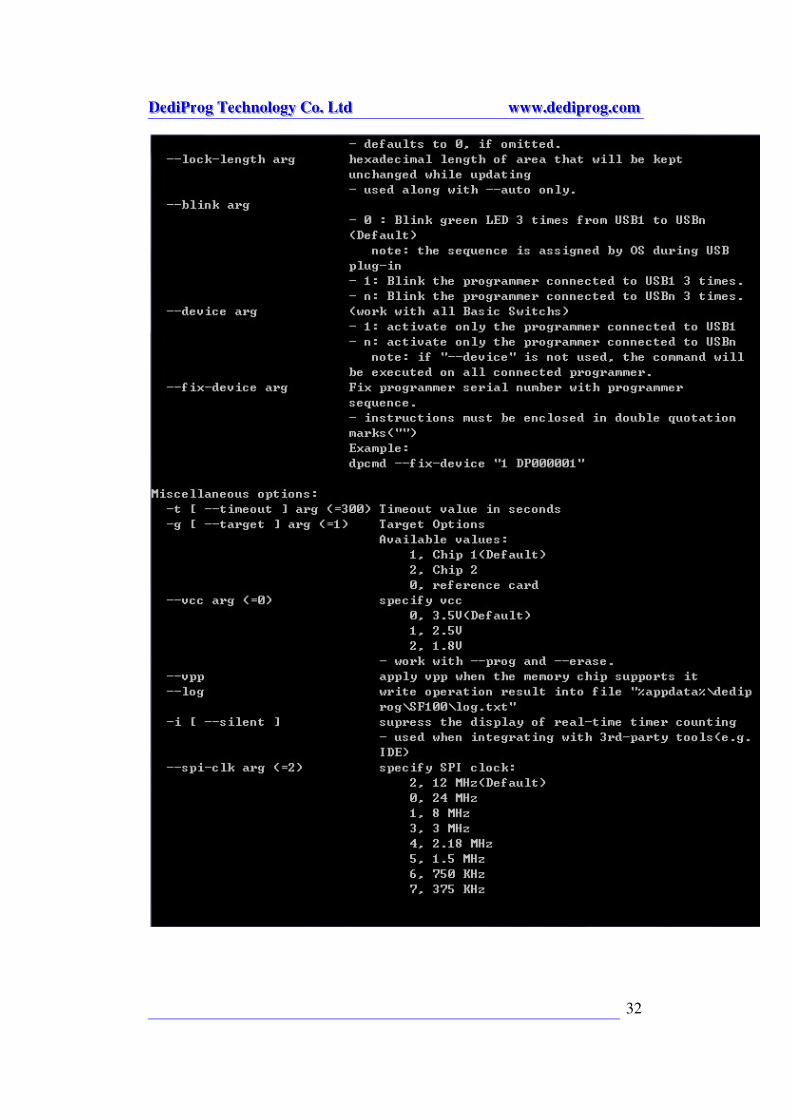
--lock-length arg hexadecimal length of area that will be kept
unchanged while updating
- used along with --auto only.
--blink arg
- 0 : Blink green LED 3 times from USB1 to USBn
(Default)
note: the sequence is assigned by OS during USB
plug-in
- 1: Blink the programmer connected to USB1 3
times.
- n: Blink the programmer connected to USBn 3 times.
DDDeeedddiiiPPPrrroooggg TTTeeeccchhhnnnooolllooogggyyy CCCooo... LLLtttddd wwwwwwwww...dddeeedddiiippprrroooggg...cccooommm
35
--device arg (work with all Basic Switchs)
- 1: activate only the programmer connected to USB1
- n: activate only the programmer connected to USBn
note: if "--device" is not used, the command will
be executed on all connected programmer.
--fix-device arg Fix programmer serial number with programmer
sequence.
- instructions must be enclosed in double quotation
marks("")
Example:
dpcmd --fix-device "1 DP000001"
Miscellaneous options:
-t [ --timeout ] arg (=300) Timeout value in seconds
-g [ --target ] arg (=1) Target Options
Available values:
1, Chip 1(Default)
2, Chip 2
0, reference card
--vcc arg (=0) specify vcc
0, 3.5V(Default)
1, 2.5V
2, 1.8V
- work with --prog and --erase.
--vpp apply vpp when the memory chip supports it
--log write operation result into file
"%appdata%\dedip
rog\SF100\log.txt"
-i [ --silent ] supress the display of real-time timer counting
- used when integrating with 3rd-party
tools(e.g. IDE)
--spi-clk arg (=2) specify SPI clock:
2, 12 MHz(Default)
0, 24 MHz
1, 8 MHz
3, 3 MHz
4, 2.18 MHz
5, 1.5 MHz
6, 750 KHz
7, 375 Khz
DDDeeedddiiiPPPrrroooggg TTTeeeccchhhnnnooolllooogggyyy CCCooo... LLLtttddd wwwwwwwww...dddeeedddiiippprrroooggg...cccooommm
36
VI. Stand Alone Mode (SF300 & SF600) In addition to the functions provided by SF100 and SF200, SF300 & 600
further allow users to program serial flash memories in the standalone mode.
1. SF300 Standalone Programming:
SF300 embeds a 128Mb memory which allows users to pre-download the
reference contents and configurations before performing the programming in
standalone mode.
Standalone mode procedures:
1. Project preparation
2. Mode switch
3. Standalone programming
A. Project Preparation In order to perform standalone programming, the contents and the
programming operation procedures have to be pre-downloaded to the SF300
through the USB with the software provided by Dediprog. SF300 has
embedded a 128Mb SPI Flash and therefore it is capable of supporting
standalone programming for all serial flash equal and under 128Mb.
Prepare a standalone programming project
1. connect the SF300 to a PC with SF software installed and make sure the
programmer is switched to USB mode
2. open the SF software and click on the “update standalone project” tab
DDDeeedddiiiPPPrrroooggg TTTeeeccchhhnnnooolllooogggyyy CCCooo... LLLtttddd wwwwwwwww...dddeeedddiiippprrroooggg...cccooommm
37
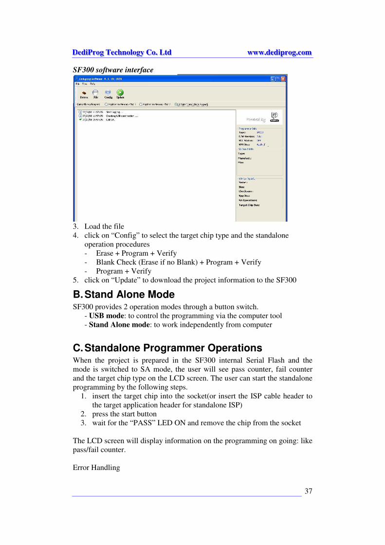
SF300 software interface
3. Load the file
4. click on “Config” to select the target chip type and the standalone
operation procedures
- Erase + Program + Verify
- Blank Check (Erase if no Blank) + Program + Verify
- Program + Verify
5. click on “Update” to download the project information to the SF300
B. Stand Alone Mode SF300 provides 2 operation modes through a button switch.
- USB mode: to control the programming via the computer tool
- Stand Alone mode: to work independently from computer
C. Standalone Programmer Operations When the project is prepared in the SF300 internal Serial Flash and the
mode is switched to SA mode, the user will see pass counter, fail counter
and the target chip type on the LCD screen. The user can start the standalone
programming by the following steps.
1. insert the target chip into the socket(or insert the ISP cable header to
the target application header for standalone ISP)
2. press the start button
3. wait for the “PASS” LED ON and remove the chip from the socket
The LCD screen will display information on the programming on going: like
pass/fail counter.
Error Handling
DDDeeedddiiiPPPrrroooggg TTTeeeccchhhnnnooolllooogggyyy CCCooo... LLLtttddd wwwwwwwww...dddeeedddiiippprrroooggg...cccooommm
38
When there is programming error occurs, the Red LED will be on. The user
can exit the error status by pressing the start button once and SF300 will
increment the fail counter.
Reset Counter
By pressing the reset button, SF300 will reset both the pass counter and fail
counter to zero.
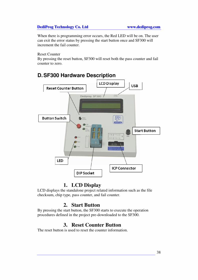
D. SF300 Hardware Description
1. LCD Display LCD displays the standalone project related information such as the file
checksum, chip type, pass counter, and fail counter.
2. Start Button By pressing the start button, the SF300 starts to execute the operation
procedures defined in the project pre-downloaded to the SF300.
3. Reset Counter Button The reset button is used to reset the counter information.

DDDeeedddiiiPPPrrroooggg TTTeeeccchhhnnnooolllooogggyyy CCCooo... LLLtttddd wwwwwwwww...dddeeedddiiippprrroooggg...cccooommm
39
4. USB Connector USB connector is used to communicate with the SF software during the
USB mode or to provide the power during the standalone mode.
5. DIP Socket DIP socket is used to connect to different socket adaptors provided by
Dediprog in order to support all serial flash packages.
6. LED Display Red Led: error
Orange Led: operation on going
Green Led: pass
2. SF600 Standalone Programming: ※※※※Please note that SF600 stand alone programming is not yet supported
and the information will be updated later
To work in Stand Alone mode, SF600 needs to be connected to DediProg
“control module” with display and Keypad. SF600 will also use the Micro SD
card to run the project.
A. Project definition from the engineering interface.
B. Save Project on the Micro SD card.
C. Run project from SF600 by using the DediProg “control module”.
A. Project preparation In order to perform stand alone programming, the contents and the
programming operation procedures have to be pre-downloaded to the SF600
Micro SD card through the USB with the software provided by Dediprog.
Prepare a standalone programming project 1. Connect the SF600 to a computer with DediProg software installed and
make sure the programmer is switched to USB mode by removing the
“control module”.
2. Load the file to be programmed.
3. Click on “Configuration” icon to select the target chip type and the
standalone operation procedures.
4. Project has to be downloaded in the SF600 Micro SD card from the user
Interface.
DDDeeedddiiiPPPrrroooggg TTTeeeccchhhnnnooolllooogggyyy CCCooo... LLLtttddd wwwwwwwww...dddeeedddiiippprrroooggg...cccooommm
40
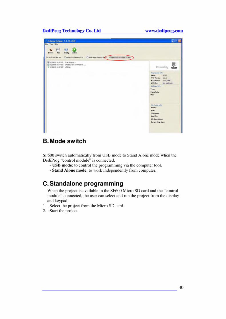
B. Mode switch
SF600 switch automatically from USB mode to Stand Alone mode when the
DediProg “control module” is connected.
- USB mode: to control the programming via the computer tool.
- Stand Alone mode: to work independently from computer.
C. Standalone programming When the project is available in the SF600 Micro SD card and the “control
module” connected, the user can select and run the project from the display
and keypad:
1. Select the project from the Micro SD card.
2. Start the project.
DDDeeedddiiiPPPrrroooggg TTTeeeccchhhnnnooolllooogggyyy CCCooo... LLLtttddd wwwwwwwww...dddeeedddiiippprrroooggg...cccooommm
41
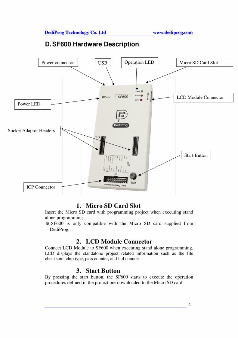
D. SF600 Hardware Description
1. Micro SD Card Slot Insert the Micro SD card with programming project when executing stand
alone programming.
※ SF600 is only compatible with the Micro SD card supplied from
DediProg.
2. LCD Module Connector Connect LCD Module to SF600 when executing stand alone programming. LCD displays the standalone project related information such as the file
checksum, chip type, pass counter, and fail counter.
3. Start Button By pressing the start button, the SF600 starts to execute the operation
procedures defined in the project pre-downloaded to the Micro SD card.
Start Button
Socket Adaptor Headers
ICP Connector
Operation LED
Power LED
LCD Module Connector
Micro SD Card Slot USB Power connector
DDDeeedddiiiPPPrrroooggg TTTeeeccchhhnnnooolllooogggyyy CCCooo... LLLtttddd wwwwwwwww...dddeeedddiiippprrroooggg...cccooommm
42
4. ICP Connector ICP connector is used to connect ICP cable when executing ICP
programming.
5. Socket Adaptor Headers Socket adaptor headers are used to connect to different socket adaptors
provided by Dediprog in order to support all serial flash packages.
6. Power LED Power LED shines when SF600 is powered by USB or power adaptor.
7. Power Connector Connect power adaptor to SF600 when executing stand alone programming.
USB can also be used as power source during standalone programming.
8. USB Connector USB connector is used to communicate with the SF software during the USB
mode or to provide the power during the standalone mode.
9. Operation LED Red Led: error
Orange Led: operation on going
Green Led: pass
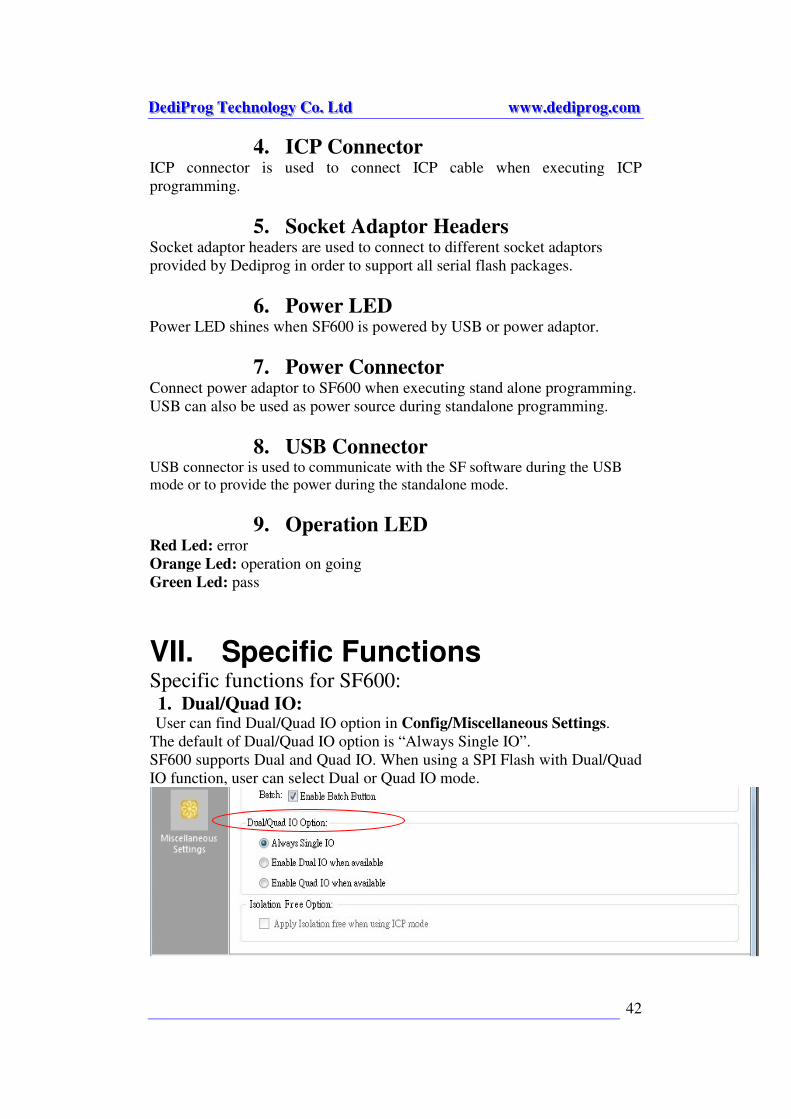
VII. Specific Functions Specific functions for SF600: 1. Dual/Quad IO: User can find Dual/Quad IO option in Config/Miscellaneous Settings.
The default of Dual/Quad IO option is “Always Single IO”.
SF600 supports Dual and Quad IO. When using a SPI Flash with Dual/Quad
IO function, user can select Dual or Quad IO mode.
DDDeeedddiiiPPPrrroooggg TTTeeeccchhhnnnooolllooogggyyy CCCooo... LLLtttddd wwwwwwwww...dddeeedddiiippprrroooggg...cccooommm
43
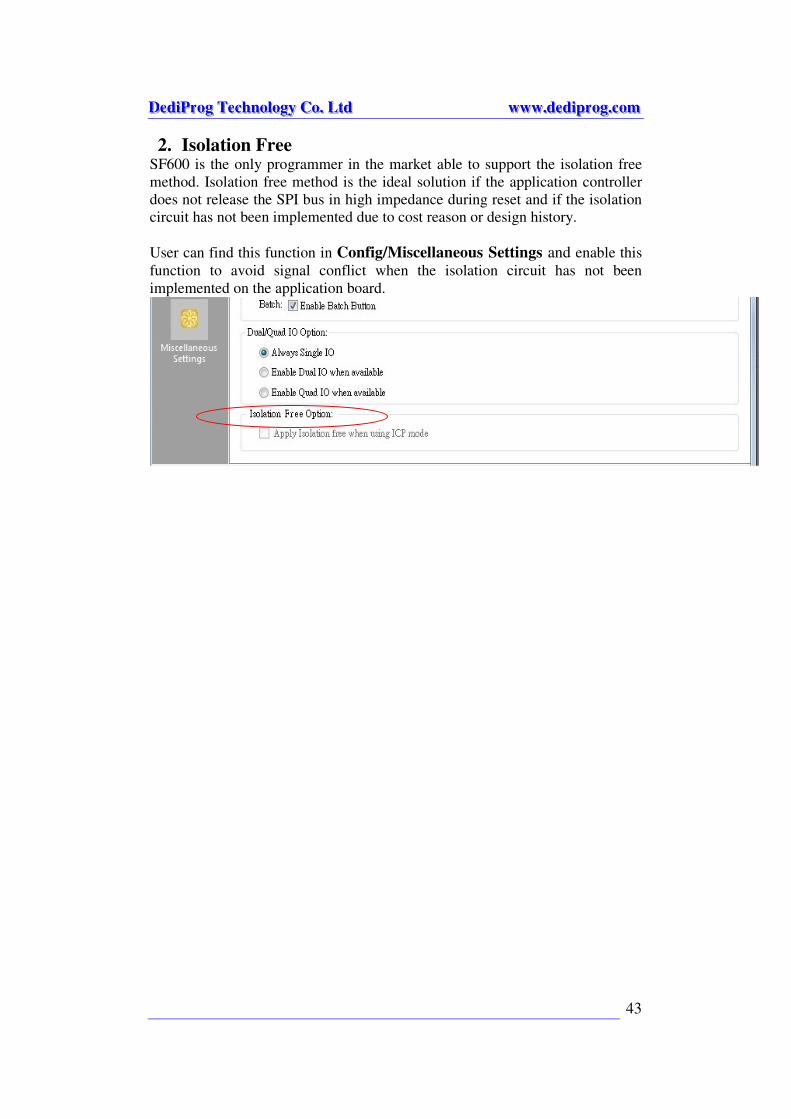
2. Isolation Free SF600 is the only programmer in the market able to support the isolation free
method. Isolation free method is the ideal solution if the application controller
does not release the SPI bus in high impedance during reset and if the isolation
circuit has not been implemented due to cost reason or design history.
User can find this function in Config/Miscellaneous Settings and enable this
function to avoid signal conflict when the isolation circuit has not been
implemented on the application board.
DDDeeedddiiiPPPrrroooggg TTTeeeccchhhnnnooolllooogggyyy CCCooo... LLLtttddd wwwwwwwww...dddeeedddiiippprrroooggg...cccooommm
44
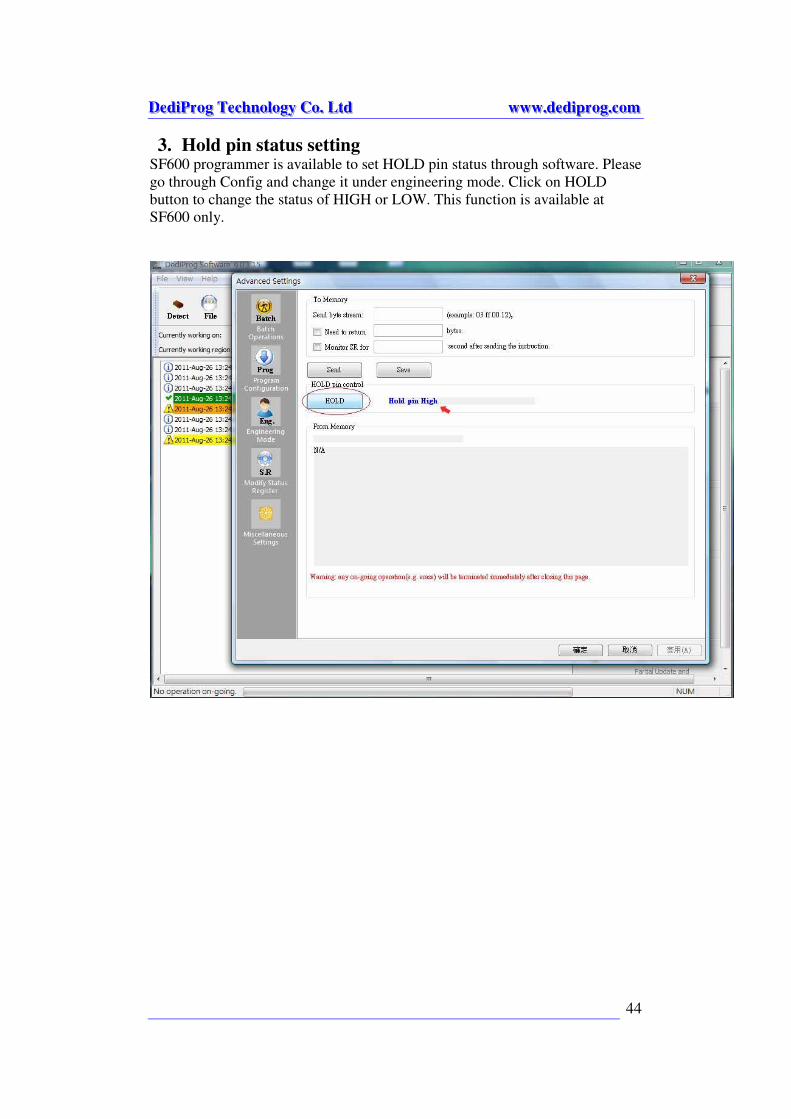
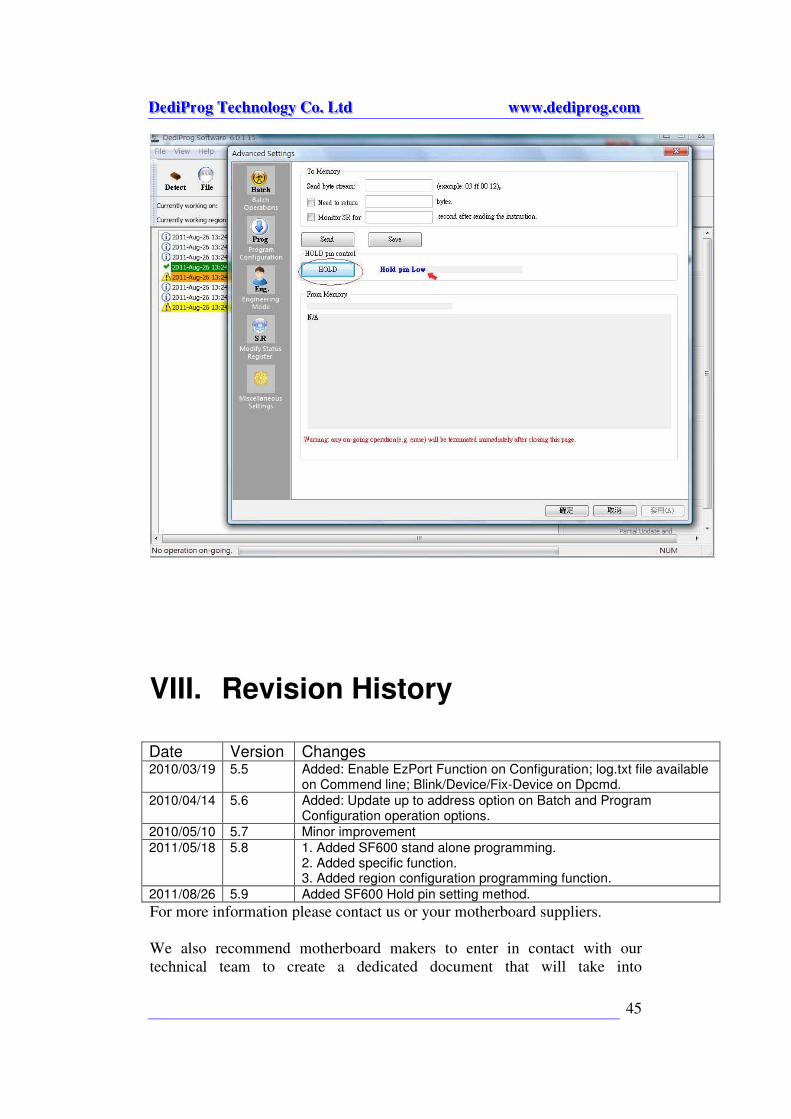
3. Hold pin status setting SF600 programmer is available to set HOLD pin status through software. Please
go through Config and change it under engineering mode. Click on HOLD
button to change the status of HIGH or LOW. This function is available at
SF600 only.
DDDeeedddiiiPPPrrroooggg TTTeeeccchhhnnnooolllooogggyyy CCCooo... LLLtttddd wwwwwwwww...dddeeedddiiippprrroooggg...cccooommm
45
VIII. Revision History
Date Version Changes 2010/03/19 5.5 Added: Enable EzPort Function on Configuration; log.txt file available
on Commend line; Blink/Device/Fix-Device on Dpcmd.
2010/04/14 5.6 Added: Update up to address option on Batch and Program Configuration operation options.
2010/05/10 5.7 Minor improvement
2011/05/18 5.8 1. Added SF600 stand alone programming. 2. Added specific function. 3. Added region configuration programming function.
2011/08/26 5.9 Added SF600 Hold pin setting method.
For more information please contact us or your motherboard suppliers.
We also recommend motherboard makers to enter in contact with our
technical team to create a dedicated document that will take into

DDDeeedddiiiPPPrrroooggg TTTeeeccchhhnnnooolllooogggyyy CCCooo... LLLtttddd wwwwwwwww...dddeeedddiiippprrroooggg...cccooommm
46
consideration all your motherboard updating constraints and references. This
documentation will then be very helpful to simplify the Bios update and
avoid any mistake in the field.
Information furnished is believed to be accurate and reliable. However,
DediProg assumes no responsibility for the consequences of use of such
information or for any infringement of patents or other rights of third parties
which may result from its use. Specifications mentioned in this publication
are subject to change without notice.
This publication supersedes and replaces all information previously supplied.
All rights reserved
Printed in Taiwan.