Embed Size (px)
Citation preview
Joint Interoperability Test Command (JTE)
MEMORANDUM FOR DISTRIBUTION 5 May 11
SUBJECT: Special Interoperability Test Certification of the Cisco® 7600 Series Release
Internetwork Operating System (IOS®) 12.2(33) SRE2
References: (a) DoD Directive 4630.05, “Interoperability and Supportability of Information
Technology (IT) and National Security Systems (NSS),” 5 May 2004
(b) CJCSI 6212.01E, “Interoperability and Supportability of Information
Technology and National Security Systems,” 15 December 2008
(c) through (e), see Enclosure 1
1. References (a) and (b) establish the Defense Information Systems Agency (DISA), Joint
Interoperability Test Command (JITC), as the responsible organization for interoperability test
certification.
2. The Cisco® 7609-S Release IOS
® 12.2(33) SRE2 is hereinafter referred to as the system under
test (SUT). The SUT meets all of its critical interoperability requirements and is certified for
joint use within the Defense Information System Network (DISN) as an Assured Services Local
Area Network (ASLAN) core, distribution, and access switch. The SUT was tested for
Multiprotocol Label Switching (MPLS) and is certified for Layer 2 and Layer 3 Virtual Private
Networks (VPNs). The SUT is certified as interoperable for joint use with other ASLAN
components listed on the Unified Capabilities (UC) Approved Products List (APL) with the
following interfaces: 10000/1000Base SX/LX, 100BaseFX, and 10/100/1000BaseT. The SUT
meets the critical interoperability requirements set forth in Reference (c), using test procedures
derived from Reference (d). The Cisco® 7603-S, 7604, 7606-S, and 7613 switches employ the
same software and hardware as the SUT. The JITC analysis determined these systems to be
functionally identical to the SUT for interoperability certification purposes and they are also
certified for joint use.
The SUT is certified to support Assured Services within an ASLAN. If a component meets the
minimum requirements for deployment in an ASLAN, it also meets the lesser requirements for
deployment in a non-ASLAN. Non-ASLANs are “commercial grade” and provide support to
Command and Control (C2) (ROUTINE only calls) (C2(R)) or non-C2 voice subscribers. The
SUT is certified for joint use deployment in a non-ASLAN for C2R and non-C2 traffic. When
deployed in a non-ASLAN, the SUT may also be used to receive all levels of precedence, but is
limited to supporting calls that are originated at ROUTINE precedence only. Non-ASLANs do
not meet the availability or redundancy requirements for C2 or Special C2 users and therefore
are not authorized to support precedence calls originated above ROUTINE.
IN REPLY REFER TO:
DEFENSE INFORMATION SYSTEMS AGENCY P. O. BOX 549
FORT MEADE, MARYLAND 20755-0549
JITC Memo, JTE, Special Interoperability Test Certification of the Cisco® 7600 Series Release
Internetwork Operating System (IOS®) 12.2(33) SRE2
2
Testing of the SUT did not include video services or data applications; however, simulated
preferred data, best effort data, and video traffic was generated during testing to determine the
SUT’s ability to prioritize and properly queue voice media and signaling traffic. No other
configurations, features, or functions, except those cited within this document, are certified by
the JITC. This certification expires upon changes that could affect interoperability, but no later
than three years from the date the DISA Field Security Operations (FSO) provided a positive
Certification and Accreditation (CA) Recommendation.
3. This finding is based on interoperability testing conducted by JITC, DISA adjudication of
open test discrepancy reports (TDRs), review of the vendor’s Letters of Compliance (LoC), and
FSO CA Recommendation. Interoperability testing was conducted by JITC at the Global
Information Grid Network Test Facility, Fort Huachuca, Arizona, from 21 June through
25 October 2010. A verification and validation was conducted from 29 November through
10 December 2010. Review of the vendor’s LoC was completed on 7 March 2011. DISA
adjudication of outstanding TDRs was completed on 18 February 2011. The FSO provided a
positive CA Recommendation on 5 May 2011 based on the security testing completed by DISA-
led IA test teams and published in a separate report, Reference (e).
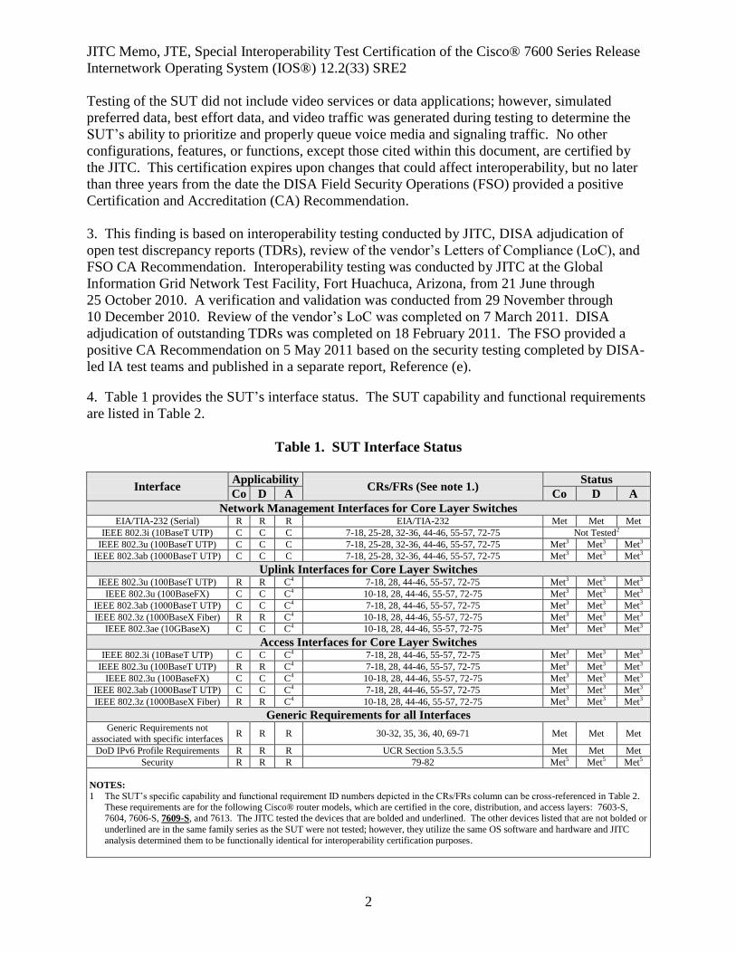
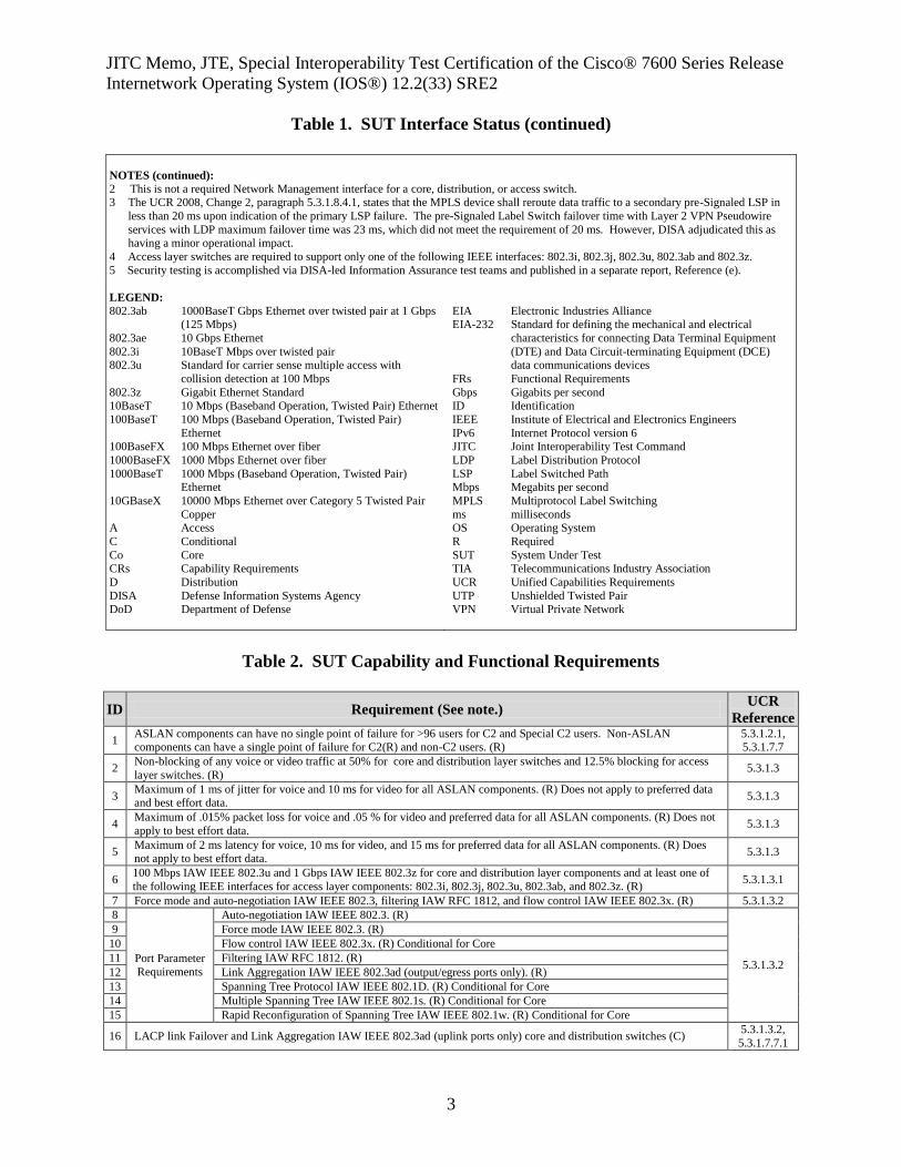
4. Table 1 provides the SUT’s interface status. The SUT capability and functional requirements
are listed in Table 2.
Table 1. SUT Interface Status
Interface Applicability
CRs/FRs (See note 1.) Status
Co D A Co D A
Network Management Interfaces for Core Layer Switches EIA/TIA-232 (Serial) R R R EIA/TIA-232 Met Met Met
IEEE 802.3i (10BaseT UTP) C C C 7-18, 25-28, 32-36, 44-46, 55-57, 72-75 Not Tested2 IEEE 802.3u (100BaseT UTP) C C C 7-18, 25-28, 32-36, 44-46, 55-57, 72-75 Met3 Met3 Met3
IEEE 802.3ab (1000BaseT UTP) C C C 7-18, 25-28, 32-36, 44-46, 55-57, 72-75 Met3 Met3 Met3 Uplink Interfaces for Core Layer Switches
IEEE 802.3u (100BaseT UTP) R R C4 7-18, 28, 44-46, 55-57, 72-75 Met3 Met3 Met3 IEEE 802.3u (100BaseFX) C C C4 10-18, 28, 44-46, 55-57, 72-75 Met3 Met3 Met3
IEEE 802.3ab (1000BaseT UTP) C C C4 7-18, 28, 44-46, 55-57, 72-75 Met3 Met3 Met3 IEEE 802.3z (1000BaseX Fiber) R R C4 10-18, 28, 44-46, 55-57, 72-75 Met3 Met3 Met3
IEEE 802.3ae (10GBaseX) C C C4 10-18, 28, 44-46, 55-57, 72-75 Met3 Met3 Met3 Access Interfaces for Core Layer Switches
IEEE 802.3i (10BaseT UTP) C C C4 7-18, 28, 44-46, 55-57, 72-75 Met3 Met3 Met3 IEEE 802.3u (100BaseT UTP) R R C4 7-18, 28, 44-46, 55-57, 72-75 Met3 Met3 Met3
IEEE 802.3u (100BaseFX) C C C4 10-18, 28, 44-46, 55-57, 72-75 Met3 Met3 Met3 IEEE 802.3ab (1000BaseT UTP) C C C4 7-18, 28, 44-46, 55-57, 72-75 Met3 Met3 Met3 IEEE 802.3z (1000BaseX Fiber) R R C4 10-18, 28, 44-46, 55-57, 72-75 Met3 Met3 Met3
Generic Requirements for all Interfaces
Generic Requirements not
associated with specific interfaces R R R 30-32, 35, 36, 40, 69-71 Met Met Met
DoD IPv6 Profile Requirements R R R UCR Section 5.3.5.5 Met Met Met Security R R R 79-82 Met5 Met5 Met5
NOTES:
1 The SUT’s specific capability and functional requirement ID numbers depicted in the CRs/FRs column can be cross-referenced in Table 2.
These requirements are for the following Cisco® router models, which are certified in the core, distribution, and access layers: 7603-S, 7604, 7606-S, 7609-S, and 7613. The JITC tested the devices that are bolded and underlined. The other devices listed that are not bolded or
underlined are in the same family series as the SUT were not tested; however, they utilize the same OS software and hardware and JITC
analysis determined them to be functionally identical for interoperability certification purposes.
JITC Memo, JTE, Special Interoperability Test Certification of the Cisco® 7600 Series Release
Internetwork Operating System (IOS®) 12.2(33) SRE2
3
Table 1. SUT Interface Status (continued)
NOTES (continued):
2 This is not a required Network Management interface for a core, distribution, or access switch. 3 The UCR 2008, Change 2, paragraph 5.3.1.8.4.1, states that the MPLS device shall reroute data traffic to a secondary pre-Signaled LSP in
less than 20 ms upon indication of the primary LSP failure. The pre-Signaled Label Switch failover time with Layer 2 VPN Pseudowire
services with LDP maximum failover time was 23 ms, which did not meet the requirement of 20 ms. However, DISA adjudicated this as having a minor operational impact.
4 Access layer switches are required to support only one of the following IEEE interfaces: 802.3i, 802.3j, 802.3u, 802.3ab and 802.3z.
5 Security testing is accomplished via DISA-led Information Assurance test teams and published in a separate report, Reference (e).
LEGEND:
802.3ab 1000BaseT Gbps Ethernet over twisted pair at 1 Gbps (125 Mbps)
802.3ae 10 Gbps Ethernet
802.3i 10BaseT Mbps over twisted pair 802.3u Standard for carrier sense multiple access with
collision detection at 100 Mbps
802.3z Gigabit Ethernet Standard 10BaseT 10 Mbps (Baseband Operation, Twisted Pair) Ethernet
100BaseT 100 Mbps (Baseband Operation, Twisted Pair)
Ethernet 100BaseFX 100 Mbps Ethernet over fiber
1000BaseFX 1000 Mbps Ethernet over fiber
1000BaseT 1000 Mbps (Baseband Operation, Twisted Pair) Ethernet
10GBaseX 10000 Mbps Ethernet over Category 5 Twisted Pair
Copper A Access
C Conditional
Co Core CRs Capability Requirements
D Distribution
DISA Defense Information Systems Agency DoD Department of Defense
EIA Electronic Industries Alliance EIA-232 Standard for defining the mechanical and electrical
characteristics for connecting Data Terminal Equipment
(DTE) and Data Circuit-terminating Equipment (DCE) data communications devices
FRs Functional Requirements
Gbps Gigabits per second ID Identification
IEEE Institute of Electrical and Electronics Engineers
IPv6 Internet Protocol version 6 JITC Joint Interoperability Test Command
LDP Label Distribution Protocol
LSP Label Switched Path Mbps Megabits per second
MPLS Multiprotocol Label Switching
ms milliseconds OS Operating System
R Required
SUT System Under Test TIA Telecommunications Industry Association
UCR Unified Capabilities Requirements
UTP Unshielded Twisted Pair VPN Virtual Private Network
Table 2. SUT Capability and Functional Requirements
ID Requirement (See note.) UCR
Reference
1 ASLAN components can have no single point of failure for >96 users for C2 and Special C2 users. Non-ASLAN components can have a single point of failure for C2(R) and non-C2 users. (R)
5.3.1.2.1, 5.3.1.7.7
2 Non-blocking of any voice or video traffic at 50% for core and distribution layer switches and 12.5% blocking for access
layer switches. (R) 5.3.1.3
3 Maximum of 1 ms of jitter for voice and 10 ms for video for all ASLAN components. (R) Does not apply to preferred data and best effort data.
5.3.1.3
4 Maximum of .015% packet loss for voice and .05 % for video and preferred data for all ASLAN components. (R) Does not
apply to best effort data. 5.3.1.3
5 Maximum of 2 ms latency for voice, 10 ms for video, and 15 ms for preferred data for all ASLAN components. (R) Does not apply to best effort data.
5.3.1.3
6 100 Mbps IAW IEEE 802.3u and 1 Gbps IAW IEEE 802.3z for core and distribution layer components and at least one of
the following IEEE interfaces for access layer components: 802.3i, 802.3j, 802.3u, 802.3ab, and 802.3z. (R) 5.3.1.3.1
7 Force mode and auto-negotiation IAW IEEE 802.3, filtering IAW RFC 1812, and flow control IAW IEEE 802.3x. (R) 5.3.1.3.2
8
Port Parameter
Requirements
Auto-negotiation IAW IEEE 802.3. (R)
5.3.1.3.2
9 Force mode IAW IEEE 802.3. (R)
10 Flow control IAW IEEE 802.3x. (R) Conditional for Core
11 Filtering IAW RFC 1812. (R)
12 Link Aggregation IAW IEEE 802.3ad (output/egress ports only). (R)
13 Spanning Tree Protocol IAW IEEE 802.1D. (R) Conditional for Core
14 Multiple Spanning Tree IAW IEEE 802.1s. (R) Conditional for Core
15 Rapid Reconfiguration of Spanning Tree IAW IEEE 802.1w. (R) Conditional for Core
16 LACP link Failover and Link Aggregation IAW IEEE 802.3ad (uplink ports only) core and distribution switches (C) 5.3.1.3.2,
5.3.1.7.7.1
JITC Memo, JTE, Special Interoperability Test Certification of the Cisco® 7600 Series Release
Internetwork Operating System (IOS®) 12.2(33) SRE2
4
Table 2. SUT Capability and Functional Requirements (continued)
ID Requirement (See note.) UCR
Reference
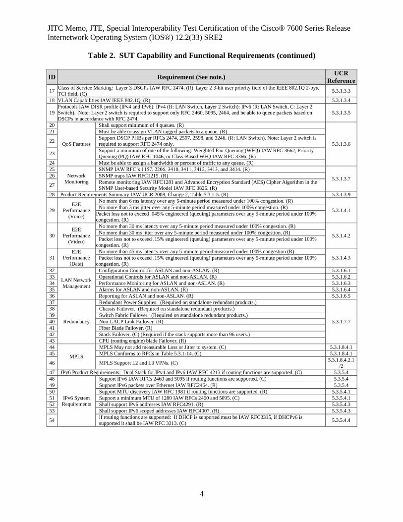
17 Class of Service Marking: Layer 3 DSCPs IAW RFC 2474. (R) Layer 2 3-bit user priority field of the IEEE 802.1Q 2-byte
TCI field. (C) 5.3.1.3.3
18 VLAN Capabilities IAW IEEE 802.1Q. (R) 5.3.1.3.4
19 Protocols IAW DISR profile (IPv4 and IPv6). IPv4 (R: LAN Switch, Layer 2 Switch): IPv6 (R: LAN Switch, C: Layer 2 Switch). Note: Layer 2 switch is required to support only RFC 2460, 5095, 2464, and be able to queue packets based on
DSCPs in accordance with RFC 2474.
5.3.1.3.5
20
QoS Features
Shall support minimum of 4 queues. (R)
5.3.1.3.6
21 Must be able to assign VLAN tagged packets to a queue. (R)
22 Support DSCP PHBs per RFCs 2474, 2597, 2598, and 3246. (R: LAN Switch). Note: Layer 2 switch is
required to support RFC 2474 only.
23 Support a minimum of one of the following: Weighted Fair Queuing (WFQ) IAW RFC 3662, Priority Queuing (PQ) IAW RFC 1046, or Class-Based WFQ IAW RFC 3366. (R)
24 Must be able to assign a bandwidth or percent of traffic to any queue. (R)
25
Network
Monitoring
SNMP IAW RFC’s 1157, 2206, 3410, 3411, 3412, 3413, and 3414. (R)
5.3.1.3.7 26 SNMP traps IAW RFC1215. (R)
27 Remote monitoring IAW RFC1281 and Advanced Encryption Standard (AES) Cipher Algorithm in the SNMP User-based Security Model IAW RFC 3826. (R)
28 Product Requirements Summary IAW UCR 2008, Change 2, Table 5.3.1-5. (R) 5.3.1.3.9
29 E2E
Performance
(Voice)
No more than 6 ms latency over any 5-minute period measured under 100% congestion. (R)
5.3.1.4.1 No more than 3 ms jitter over any 5-minute period measured under 100% congestion. (R)
Packet loss not to exceed .045% engineered (queuing) parameters over any 5-minute period under 100% congestion. (R)
30
E2E
Performance (Video)
No more than 30 ms latency over any 5-minute period measured under 100% congestion. (R)
5.3.1.4.2 No more than 30 ms jitter over any 5-minute period measured under 100% congestion. (R)
Packet loss not to exceed .15% engineered (queuing) parameters over any 5-minute period under 100% congestion. (R)
31 E2E
Performance
(Data)
No more than 45 ms latency over any 5-minute period measured under 100% congestion (R)
5.3.1.4.3 Packet loss not to exceed .15% engineered (queuing) parameters over any 5-minute period under 100%
congestion. (R)
32
LAN Network
Management
Configuration Control for ASLAN and non-ASLAN. (R) 5.3.1.6.1
33 Operational Controls for ASLAN and non-ASLAN. (R) 5.3.1.6.2
34 Performance Monitoring for ASLAN and non-ASLAN. (R) 5.3.1.6.3
35 Alarms for ASLAN and non-ASLAN. (R) 5.3.1.6.4
36 Reporting for ASLAN and non-ASLAN. (R) 5.3.1.6.5
37
Redundancy
Redundant Power Supplies. (Required on standalone redundant products.)
5.3.1.7.7
38 Chassis Failover. (Required on standalone redundant products.)
39 Switch Fabric Failover. (Required on standalone redundant products.)
40 Non-LACP Link Failover. (R)
41 Fiber Blade Failover. (R)
42 Stack Failover. (C) (Required if the stack supports more than 96 users.)
43 CPU (routing engine) blade Failover. (R)
44
MPLS
MPLS May not add measurable Loss or Jitter to system. (C) 5.3.1.8.4.1
45 MPLS Conforms to RFCs in Table 5.3.1-14. (C) 5.3.1.8.4.1
46 MPLS Support L2 and L3 VPNs. (C) 5.3.1.8.4.2.1
/2
47 IPv6 Product Requirements: Dual Stack for IPv4 and IPv6 IAW RFC 4213 if routing functions are supported. (C) 5.3.5.4
48
IPv6 System
Requirements
Support IPv6 IAW RFCs 2460 and 5095 if routing functions are supported. (C) 5.3.5.4
49 Support IPv6 packets over Ethernet IAW RFC2464. (R) 5.3.5.4
50 Support MTU discovery IAW RFC 1981 if routing functions are supported. (R) 5.3.5.4.1
51 Support a minimum MTU of 1280 IAW RFCs 2460 and 5095. (C) 5.3.5.4.1
52 Shall support IPv6 addresses IAW RFC4291. (R) 5.3.5.4.3
53 Shall support IPv6 scoped addresses IAW RFC4007. (R) 5.3.5.4.3
54 if routing functions are supported: If DHCP is supported must be IAW RFC3315, if DHCPv6 is supported it shall be IAW RFC 3313. (C)
5.3.5.4.4
JITC Memo, JTE, Special Interoperability Test Certification of the Cisco® 7600 Series Release
Internetwork Operating System (IOS®) 12.2(33) SRE2
5
Table 2. SUT Capability and Functional Requirements (continued)
ID Requirement (See note.) UCR
Reference
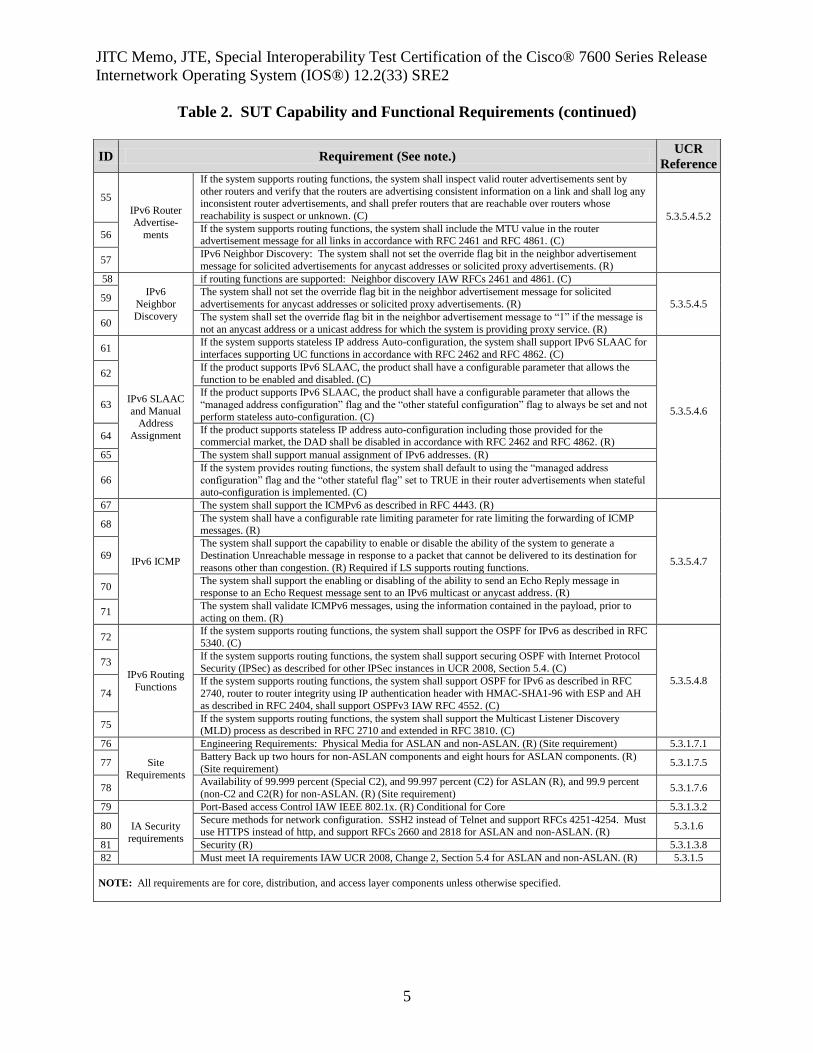
55
IPv6 Router Advertise-
ments
If the system supports routing functions, the system shall inspect valid router advertisements sent by
other routers and verify that the routers are advertising consistent information on a link and shall log any inconsistent router advertisements, and shall prefer routers that are reachable over routers whose
reachability is suspect or unknown. (C) 5.3.5.4.5.2
56
If the system supports routing functions, the system shall include the MTU value in the router advertisement message for all links in accordance with RFC 2461 and RFC 4861. (C)
57 IPv6 Neighbor Discovery: The system shall not set the override flag bit in the neighbor advertisement
message for solicited advertisements for anycast addresses or solicited proxy advertisements. (R)
58
IPv6
Neighbor
Discovery
if routing functions are supported: Neighbor discovery IAW RFCs 2461 and 4861. (C)
5.3.5.4.5 59
The system shall not set the override flag bit in the neighbor advertisement message for solicited
advertisements for anycast addresses or solicited proxy advertisements. (R)
60 The system shall set the override flag bit in the neighbor advertisement message to “1” if the message is
not an anycast address or a unicast address for which the system is providing proxy service. (R)
61
IPv6 SLAAC
and Manual Address
Assignment
If the system supports stateless IP address Auto-configuration, the system shall support IPv6 SLAAC for
interfaces supporting UC functions in accordance with RFC 2462 and RFC 4862. (C)
5.3.5.4.6
62 If the product supports IPv6 SLAAC, the product shall have a configurable parameter that allows the
function to be enabled and disabled. (C)
63
If the product supports IPv6 SLAAC, the product shall have a configurable parameter that allows the
“managed address configuration” flag and the “other stateful configuration” flag to always be set and not
perform stateless auto-configuration. (C)
64 If the product supports stateless IP address auto-configuration including those provided for the commercial market, the DAD shall be disabled in accordance with RFC 2462 and RFC 4862. (R)
65 The system shall support manual assignment of IPv6 addresses. (R)
66
If the system provides routing functions, the system shall default to using the “managed address
configuration” flag and the “other stateful flag” set to TRUE in their router advertisements when stateful auto-configuration is implemented. (C)
67
IPv6 ICMP
The system shall support the ICMPv6 as described in RFC 4443. (R)
5.3.5.4.7
68 The system shall have a configurable rate limiting parameter for rate limiting the forwarding of ICMP
messages. (R)
69
The system shall support the capability to enable or disable the ability of the system to generate a
Destination Unreachable message in response to a packet that cannot be delivered to its destination for
reasons other than congestion. (R) Required if LS supports routing functions.
70 The system shall support the enabling or disabling of the ability to send an Echo Reply message in response to an Echo Request message sent to an IPv6 multicast or anycast address. (R)
71 The system shall validate ICMPv6 messages, using the information contained in the payload, prior to
acting on them. (R)
72
IPv6 Routing
Functions
If the system supports routing functions, the system shall support the OSPF for IPv6 as described in RFC
5340. (C)
5.3.5.4.8
73 If the system supports routing functions, the system shall support securing OSPF with Internet Protocol
Security (IPSec) as described for other IPSec instances in UCR 2008, Section 5.4. (C)
74
If the system supports routing functions, the system shall support OSPF for IPv6 as described in RFC
2740, router to router integrity using IP authentication header with HMAC-SHA1-96 with ESP and AH
as described in RFC 2404, shall support OSPFv3 IAW RFC 4552. (C)
75 If the system supports routing functions, the system shall support the Multicast Listener Discovery (MLD) process as described in RFC 2710 and extended in RFC 3810. (C)
76
Site
Requirements
Engineering Requirements: Physical Media for ASLAN and non-ASLAN. (R) (Site requirement) 5.3.1.7.1
77 Battery Back up two hours for non-ASLAN components and eight hours for ASLAN components. (R)
(Site requirement) 5.3.1.7.5
78 Availability of 99.999 percent (Special C2), and 99.997 percent (C2) for ASLAN (R), and 99.9 percent
(non-C2 and C2(R) for non-ASLAN. (R) (Site requirement) 5.3.1.7.6
79
IA Security
requirements
Port-Based access Control IAW IEEE 802.1x. (R) Conditional for Core 5.3.1.3.2
80 Secure methods for network configuration. SSH2 instead of Telnet and support RFCs 4251-4254. Must use HTTPS instead of http, and support RFCs 2660 and 2818 for ASLAN and non-ASLAN. (R)
5.3.1.6
81 Security (R) 5.3.1.3.8
82 Must meet IA requirements IAW UCR 2008, Change 2, Section 5.4 for ASLAN and non-ASLAN. (R) 5.3.1.5
NOTE: All requirements are for core, distribution, and access layer components unless otherwise specified.
JITC Memo, JTE, Special Interoperability Test Certification of the Cisco® 7600 Series Release
Internetwork Operating System (IOS®) 12.2(33) SRE2
6
Table 2. SUT Capability and Functional Requirements (continued)
LEGEND:
AH Authentication Header ASLAN Assured Services Local Area
Network
C Conditional C2 Command and Control
C2(R) Command and Control ROUTINE
only CPU Central Processing Unit
DAD Duplicate Address Detection
DHCP Dynamic Host Configuration Protocol
DHCPv6 Dynamic Host Configuration
Protocol for IPv6 DISR Department of Defense
Information Technology
Standards Registry DSCP Differentiated Services Code
Point
E2E End-to-End ESP Encapsulating Security Payload
Gbps Gigabits per second
HMAC Hash-based Message Authentication Code
HTTP Hypertext Transfer Protocol HTTPS Hyper Text Transfer Protocol,
Secure
IA Information Assurance IAW in accordance with
ICMP Internet Control Message
Protocol ICMPv6 Internet Control Message
Protocol for IPv6
ID Identification IEEE Institute of Electrical and
Electronics Engineers
IPv4 Internet Protocol version 4 IPv6 Internet Protocol version 6
L2 Layer 2
L3 Layer 3 LACP Link Aggregation Control
Protocol
LAN Local Area Network LS LAN Switch
Mbps Megabits per second
MPLS Multiprotocol Label Switching
ms millisecond MTU Maximum Transmission Unit
OSPF Open Shortest Path First
OSPFv3 Open Shortest Path First Version 3
PHB Per Hop Behavior
QoS Quality of Service R Required
RFC Request for Comments
SHA Secure Hash Algorithm SLAAC Stateless Auto Address
Configuration
SNMP Simple Network Management Protocol
SSH2 Secure Shell Version 2
SUT System Under Test TCI Tag Control Information
UC Unified Capabilities
UCR Unified Capabilities Requirements
VLAN Virtual Local Area Network
VPN Virtual Private Network
5. No detailed test report was developed in accordance with the Program Manager’s request.
JITC distributes interoperability information via the JITC Electronic Report Distribution (ERD)
system, which uses Unclassified-But-Sensitive Internet Protocol Router Network (NIPRNet) e-
mail. More comprehensive interoperability status information is available via the JITC System
Tracking Program (STP). The STP is accessible by .mil/gov users on the NIPRNet at
https://stp.fhu.disa.mil. Test reports, lessons learned, and related testing documents and
references are on the JITC Joint Interoperability Tool (JIT) at https://jit.fhu.disa.mil (NIPRNet).
Information related to DSN testing is on the Telecom Switched Services Interoperability (TSSI)
website at http://jitc.fhu.disa.mil/tssi. Due to the sensitivity of the information, the Information
Assurance Accreditation Package (IAAP) that contains the approved configuration and
deployment guide must be requested directly through government civilian or uniformed military
personnel from the Unified Capabilities Certification Office (UCCO), e-mail: [email protected].
6. The JITC point of contact is Mr. Edward Mellon, DSN 879-5159, commercial (520) 538-5159,
FAX DSN 879-4347, or e-mail to [email protected]. The JITC’s mailing address is P.O.
Box 12798, Fort Huachuca, AZ 85670-2798. The Tracking Number for the SUT is 1002801.
FOR THE COMMANDER:
2 Enclosures a/s
for BRADLEY A. CLARK
Chief
Battlespace Communications Portfolio
JITC Memo, JTE, Special Interoperability Test Certification of the Cisco® 7600 Series Release
Internetwork Operating System (IOS®) 12.2(33) SRE2
7
Distribution (electronic mail):
Joint Staff J-6
Joint Interoperability Test Command, Liaison, TE3/JT1
Office of Chief of Naval Operations, CNO N6F2
Headquarters U.S. Air Force, Office of Warfighting Integration & CIO, AF/XCIN (A6N)
Department of the Army, Office of the Secretary of the Army, DA-OSA CIO/G-6 ASA (ALT),
SAIS-IOQ
U.S. Marine Corps MARCORSYSCOM, SIAT, MJI Division I
DOT&E, Net-Centric Systems and Naval Warfare
U.S. Coast Guard, CG-64
Defense Intelligence Agency
National Security Agency, DT
Defense Information Systems Agency, TEMC
Office of Assistant Secretary of Defense (NII)/DOD CIO
U.S. Joint Forces Command, Net-Centric Integration, Communication, and Capabilities
Division, J68
Defense Information Systems Agency, GS23
Enclosure 1
ADDITIONAL REFERENCES
(c) Office of the Assistant Secretary of Defense, “Department of Defense Unified Capabilities
Requirements 2008 Change 2,” 31 December 2010
(d) Joint Interoperability Test Command, “Defense Switched Network Generic Switch Test
Plan (GSTP), Change 2,” 2 October 2006
(e) Joint Interoperability Test Command, “Information Assurance (IA) Assessment of Cisco
7609-S with Route Service Processor (RSP)720-10 Gigabit Ethernet (GE)/GE Internetwork
Operating System (IOS) 12.2(33)SRE (Tracking Number 1002801),” 5 May 2011
Enclosure 2
CERTIFICATION TESTING SUMMARY
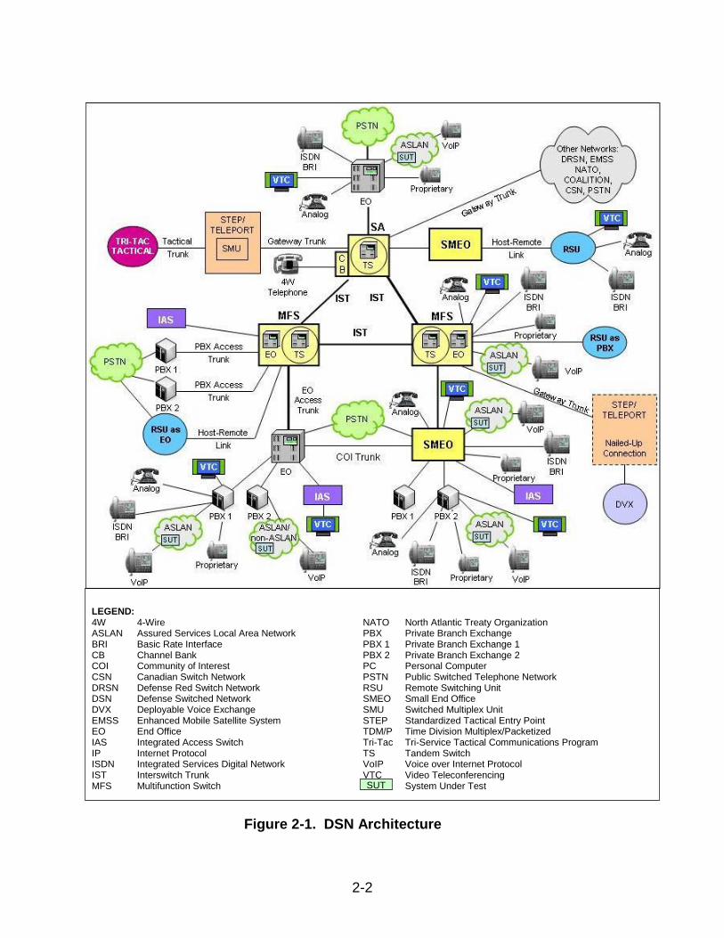
1. SYSTEM TITLE. Cisco® 7600 Series Release Internetwork Operating System (IOS®) 12.2(33) SRE2; hereinafter referred to as the system under test (SUT). 2. PROPONENT. Headquarters United States Army Information Systems Engineering Command (HQUSAISEC). 3. PROGRAM MANAGER. Mr. Jordan Silk, ELIE-ISE-TI, Building 53302, Fort Huachuca, Arizona, 85613-5300, e-mail: [email protected]. 4. TESTER. Joint Interoperability Test Command (JITC), Fort Huachuca, Arizona. 5. SYSTEM UNDER TEST DESCRIPTION. The SUT is used to transport voice signaling and media as part of an overall Voice over Internet Protocol (VoIP) system. The SUT provides availability, security, and Quality of Service (QoS) to meet the operational requirements of the network and Assured Services for the Warfighter. The SUT is certified as a core, distribution, and access switch and is interoperable for joint use with other Assured Services Local Area Network ASLAN components listed on the Unified Capabilities (UC) Approved Products List (APL) with the following interfaces: 10000/1000Base SX/LX, 100BaseFX, and 10/100/1000BaseT. The SUT was tested for Multiprotocol Label Switching (MPLS) and is certified for Layer 2 and Layer 3 Virtual Private Networks (VPNs). The Cisco® 7609-S was the system tested; however, the Cisco® 7603-S, 7604, 7606-S, and 7613 employ the same software and similar hardware as the SUT. The JITC analysis determined these systems to be functionally identical to the SUT for interoperability certification purposes. 6. OPERATIONAL ARCHITECTURE. The Defense Switched Network (DSN) architecture is a two-level network hierarchy consisting of DSN backbone switches and Service/Agency installation switches. Service/Agency installation switches have been authorized to extend voice services over Internet Protocol (IP) infrastructures. The Unified Capabilities Requirements (UCR) operational DSN Architecture is depicted in Figure 2-1, which depicts the relationship of the ASLAN and non-ASLAN to the DSN switch types.
2-2
LEGEND: 4W 4-Wire ASLAN Assured Services Local Area Network BRI Basic Rate Interface CB Channel Bank COI Community of Interest CSN Canadian Switch Network DRSN Defense Red Switch Network DSN Defense Switched Network DVX Deployable Voice Exchange EMSS Enhanced Mobile Satellite System EO End Office IAS Integrated Access Switch IP Internet Protocol ISDN Integrated Services Digital Network IST Interswitch Trunk MFS Multifunction Switch
NATO North Atlantic Treaty Organization PBX Private Branch Exchange PBX 1 Private Branch Exchange 1 PBX 2 Private Branch Exchange 2 PC Personal Computer PSTN Public Switched Telephone Network RSU Remote Switching Unit SMEO Small End Office SMU Switched Multiplex Unit STEP Standardized Tactical Entry Point TDM/P Time Division Multiplex/Packetized Tri-Tac Tri-Service Tactical Communications Program TS Tandem Switch VoIP Voice over Internet Protocol VTC Video Teleconferencing System Under Test
Figure 2-1. DSN Architecture
SUT
2-3
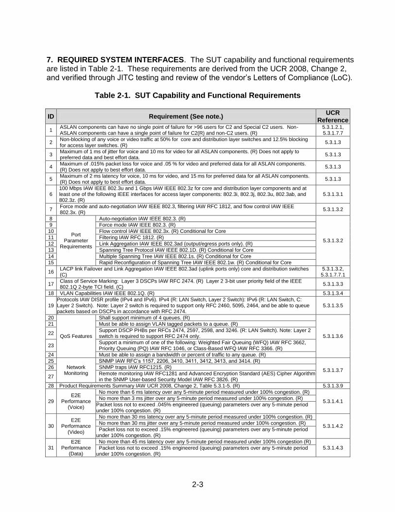
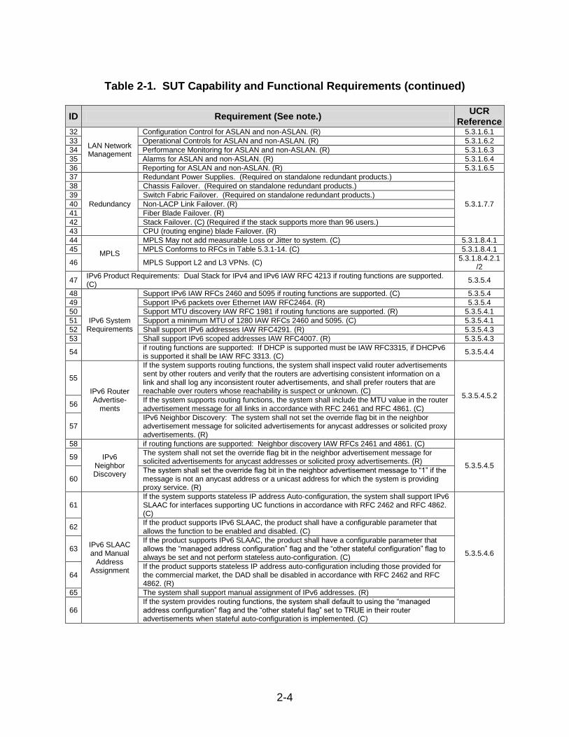
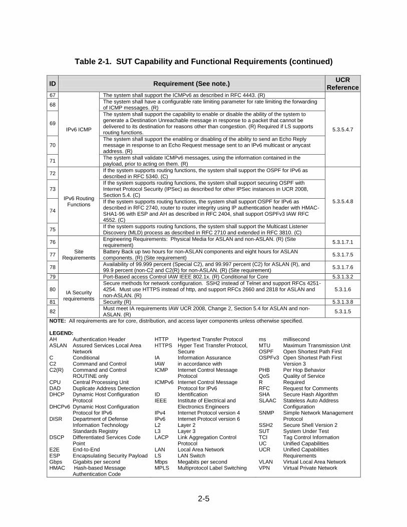
7. REQUIRED SYSTEM INTERFACES. The SUT capability and functional requirements are listed in Table 2-1. These requirements are derived from the UCR 2008, Change 2, and verified through JITC testing and review of the vendor’s Letters of Compliance (LoC).
Table 2-1. SUT Capability and Functional Requirements
ID Requirement (See note.) UCR
Reference
1 ASLAN components can have no single point of failure for >96 users for C2 and Special C2 users. Non-ASLAN components can have a single point of failure for C2(R) and non-C2 users. (R)
5.3.1.2.1, 5.3.1.7.7
2 Non-blocking of any voice or video traffic at 50% for core and distribution layer switches and 12.5% blocking for access layer switches. (R)
5.3.1.3
3 Maximum of 1 ms of jitter for voice and 10 ms for video for all ASLAN components. (R) Does not apply to preferred data and best effort data.
5.3.1.3
4 Maximum of .015% packet loss for voice and .05 % for video and preferred data for all ASLAN components. (R) Does not apply to best effort data.
5.3.1.3
5 Maximum of 2 ms latency for voice, 10 ms for video, and 15 ms for preferred data for all ASLAN components. (R) Does not apply to best effort data.
5.3.1.3
6 100 Mbps IAW IEEE 802.3u and 1 Gbps IAW IEEE 802.3z for core and distribution layer components and at least one of the following IEEE interfaces for access layer components: 802.3i, 802.3j, 802.3u, 802.3ab, and 802.3z. (R)
5.3.1.3.1
7 Force mode and auto-negotiation IAW IEEE 802.3, filtering IAW RFC 1812, and flow control IAW IEEE 802.3x. (R)
5.3.1.3.2
8
Port Parameter
Requirements
Auto-negotiation IAW IEEE 802.3. (R)
5.3.1.3.2
9 Force mode IAW IEEE 802.3. (R)
10 Flow control IAW IEEE 802.3x. (R) Conditional for Core
11 Filtering IAW RFC 1812. (R)
12 Link Aggregation IAW IEEE 802.3ad (output/egress ports only). (R)
13 Spanning Tree Protocol IAW IEEE 802.1D. (R) Conditional for Core
14 Multiple Spanning Tree IAW IEEE 802.1s. (R) Conditional for Core
15 Rapid Reconfiguration of Spanning Tree IAW IEEE 802.1w. (R) Conditional for Core
16 LACP link Failover and Link Aggregation IAW IEEE 802.3ad (uplink ports only) core and distribution switches (C)
5.3.1.3.2, 5.3.1.7.7.1
17 Class of Service Marking: Layer 3 DSCPs IAW RFC 2474. (R) Layer 2 3-bit user priority field of the IEEE 802.1Q 2-byte TCI field. (C)
5.3.1.3.3
18 VLAN Capabilities IAW IEEE 802.1Q. (R) 5.3.1.3.4
19 Protocols IAW DISR profile (IPv4 and IPv6). IPv4 (R: LAN Switch, Layer 2 Switch): IPv6 (R: LAN Switch, C: Layer 2 Switch). Note: Layer 2 switch is required to support only RFC 2460, 5095, 2464, and be able to queue packets based on DSCPs in accordance with RFC 2474.
5.3.1.3.5
20
QoS Features
Shall support minimum of 4 queues. (R)
5.3.1.3.6
21 Must be able to assign VLAN tagged packets to a queue. (R)
22 Support DSCP PHBs per RFCs 2474, 2597, 2598, and 3246. (R: LAN Switch). Note: Layer 2 switch is required to support RFC 2474 only.
23 Support a minimum of one of the following: Weighted Fair Queuing (WFQ) IAW RFC 3662, Priority Queuing (PQ) IAW RFC 1046, or Class-Based WFQ IAW RFC 3366. (R)
24 Must be able to assign a bandwidth or percent of traffic to any queue. (R)
25
Network Monitoring
SNMP IAW RFC’s 1157, 2206, 3410, 3411, 3412, 3413, and 3414. (R)
5.3.1.3.7 26 SNMP traps IAW RFC1215. (R)
27 Remote monitoring IAW RFC1281 and Advanced Encryption Standard (AES) Cipher Algorithm in the SNMP User-based Security Model IAW RFC 3826. (R)
28 Product Requirements Summary IAW UCR 2008, Change 2, Table 5.3.1-5. (R) 5.3.1.3.9
29 E2E
Performance (Voice)
No more than 6 ms latency over any 5-minute period measured under 100% congestion. (R)
5.3.1.4.1 No more than 3 ms jitter over any 5-minute period measured under 100% congestion. (R)
Packet loss not to exceed .045% engineered (queuing) parameters over any 5-minute period under 100% congestion. (R)
30 E2E
Performance (Video)
No more than 30 ms latency over any 5-minute period measured under 100% congestion. (R)
5.3.1.4.2 No more than 30 ms jitter over any 5-minute period measured under 100% congestion. (R)
Packet loss not to exceed .15% engineered (queuing) parameters over any 5-minute period under 100% congestion. (R)
31 E2E
Performance (Data)
No more than 45 ms latency over any 5-minute period measured under 100% congestion (R)
5.3.1.4.3 Packet loss not to exceed .15% engineered (queuing) parameters over any 5-minute period under 100% congestion. (R)
2-4
Table 2-1. SUT Capability and Functional Requirements (continued)
ID Requirement (See note.) UCR
Reference 32
LAN Network Management
Configuration Control for ASLAN and non-ASLAN. (R) 5.3.1.6.1
33 Operational Controls for ASLAN and non-ASLAN. (R) 5.3.1.6.2
34 Performance Monitoring for ASLAN and non-ASLAN. (R) 5.3.1.6.3
35 Alarms for ASLAN and non-ASLAN. (R) 5.3.1.6.4
36 Reporting for ASLAN and non-ASLAN. (R) 5.3.1.6.5
37
Redundancy
Redundant Power Supplies. (Required on standalone redundant products.)
5.3.1.7.7
38 Chassis Failover. (Required on standalone redundant products.)
39 Switch Fabric Failover. (Required on standalone redundant products.)
40 Non-LACP Link Failover. (R)
41 Fiber Blade Failover. (R)
42 Stack Failover. (C) (Required if the stack supports more than 96 users.)
43 CPU (routing engine) blade Failover. (R)
44
MPLS
MPLS May not add measurable Loss or Jitter to system. (C) 5.3.1.8.4.1
45 MPLS Conforms to RFCs in Table 5.3.1-14. (C) 5.3.1.8.4.1
46 MPLS Support L2 and L3 VPNs. (C) 5.3.1.8.4.2.1
/2
47 IPv6 Product Requirements: Dual Stack for IPv4 and IPv6 IAW RFC 4213 if routing functions are supported. (C)
5.3.5.4
48
IPv6 System Requirements
Support IPv6 IAW RFCs 2460 and 5095 if routing functions are supported. (C) 5.3.5.4
49 Support IPv6 packets over Ethernet IAW RFC2464. (R) 5.3.5.4
50 Support MTU discovery IAW RFC 1981 if routing functions are supported. (R) 5.3.5.4.1
51 Support a minimum MTU of 1280 IAW RFCs 2460 and 5095. (C) 5.3.5.4.1
52 Shall support IPv6 addresses IAW RFC4291. (R) 5.3.5.4.3
53 Shall support IPv6 scoped addresses IAW RFC4007. (R) 5.3.5.4.3
54 if routing functions are supported: If DHCP is supported must be IAW RFC3315, if DHCPv6 is supported it shall be IAW RFC 3313. (C)
5.3.5.4.4
55
IPv6 Router Advertise-
ments
If the system supports routing functions, the system shall inspect valid router advertisements sent by other routers and verify that the routers are advertising consistent information on a link and shall log any inconsistent router advertisements, and shall prefer routers that are reachable over routers whose reachability is suspect or unknown. (C)
5.3.5.4.5.2 56
If the system supports routing functions, the system shall include the MTU value in the router advertisement message for all links in accordance with RFC 2461 and RFC 4861. (C)
57 IPv6 Neighbor Discovery: The system shall not set the override flag bit in the neighbor advertisement message for solicited advertisements for anycast addresses or solicited proxy advertisements. (R)
58
IPv6 Neighbor Discovery
if routing functions are supported: Neighbor discovery IAW RFCs 2461 and 4861. (C)
5.3.5.4.5 59
The system shall not set the override flag bit in the neighbor advertisement message for solicited advertisements for anycast addresses or solicited proxy advertisements. (R)
60 The system shall set the override flag bit in the neighbor advertisement message to “1” if the message is not an anycast address or a unicast address for which the system is providing proxy service. (R)
61
IPv6 SLAAC and Manual
Address Assignment
If the system supports stateless IP address Auto-configuration, the system shall support IPv6 SLAAC for interfaces supporting UC functions in accordance with RFC 2462 and RFC 4862. (C)
5.3.5.4.6
62 If the product supports IPv6 SLAAC, the product shall have a configurable parameter that allows the function to be enabled and disabled. (C)
63 If the product supports IPv6 SLAAC, the product shall have a configurable parameter that allows the “managed address configuration” flag and the “other stateful configuration” flag to always be set and not perform stateless auto-configuration. (C)
64 If the product supports stateless IP address auto-configuration including those provided for the commercial market, the DAD shall be disabled in accordance with RFC 2462 and RFC 4862. (R)
65 The system shall support manual assignment of IPv6 addresses. (R)
66 If the system provides routing functions, the system shall default to using the “managed address configuration” flag and the “other stateful flag” set to TRUE in their router advertisements when stateful auto-configuration is implemented. (C)
2-5
Table 2-1. SUT Capability and Functional Requirements (continued)
ID Requirement (See note.) UCR
Reference 67
IPv6 ICMP
The system shall support the ICMPv6 as described in RFC 4443. (R)
5.3.5.4.7
68 The system shall have a configurable rate limiting parameter for rate limiting the forwarding of ICMP messages. (R)
69
The system shall support the capability to enable or disable the ability of the system to generate a Destination Unreachable message in response to a packet that cannot be delivered to its destination for reasons other than congestion. (R) Required if LS supports routing functions.
70 The system shall support the enabling or disabling of the ability to send an Echo Reply message in response to an Echo Request message sent to an IPv6 multicast or anycast address. (R)
71 The system shall validate ICMPv6 messages, using the information contained in the payload, prior to acting on them. (R)
72
IPv6 Routing Functions
If the system supports routing functions, the system shall support the OSPF for IPv6 as described in RFC 5340. (C)
5.3.5.4.8
73 If the system supports routing functions, the system shall support securing OSPF with Internet Protocol Security (IPSec) as described for other IPSec instances in UCR 2008, Section 5.4. (C)
74
If the system supports routing functions, the system shall support OSPF for IPv6 as described in RFC 2740, router to router integrity using IP authentication header with HMAC-SHA1-96 with ESP and AH as described in RFC 2404, shall support OSPFv3 IAW RFC 4552. (C)
75 If the system supports routing functions, the system shall support the Multicast Listener Discovery (MLD) process as described in RFC 2710 and extended in RFC 3810. (C)
76
Site Requirements
Engineering Requirements: Physical Media for ASLAN and non-ASLAN. (R) (Site requirement)
5.3.1.7.1
77 Battery Back up two hours for non-ASLAN components and eight hours for ASLAN components. (R) (Site requirement)
5.3.1.7.5
78 Availability of 99.999 percent (Special C2), and 99.997 percent (C2) for ASLAN (R), and 99.9 percent (non-C2 and C2(R) for non-ASLAN. (R) (Site requirement)
5.3.1.7.6
79
IA Security requirements
Port-Based access Control IAW IEEE 802.1x. (R) Conditional for Core 5.3.1.3.2
80 Secure methods for network configuration. SSH2 instead of Telnet and support RFCs 4251-4254. Must use HTTPS instead of http, and support RFCs 2660 and 2818 for ASLAN and non-ASLAN. (R)
5.3.1.6
81 Security (R) 5.3.1.3.8
82 Must meet IA requirements IAW UCR 2008, Change 2, Section 5.4 for ASLAN and non-ASLAN. (R)
5.3.1.5
NOTE: All requirements are for core, distribution, and access layer components unless otherwise specified. LEGEND: AH Authentication Header ASLAN Assured Services Local Area
Network C Conditional C2 Command and Control C2(R) Command and Control
ROUTINE only CPU Central Processing Unit DAD Duplicate Address Detection DHCP Dynamic Host Configuration
Protocol DHCPv6 Dynamic Host Configuration
Protocol for IPv6 DISR Department of Defense
Information Technology Standards Registry
DSCP Differentiated Services Code Point
E2E End-to-End ESP Encapsulating Security Payload Gbps Gigabits per second HMAC Hash-based Message
Authentication Code
HTTP Hypertext Transfer Protocol HTTPS Hyper Text Transfer Protocol,
Secure IA Information Assurance IAW in accordance with ICMP Internet Control Message
Protocol ICMPv6 Internet Control Message
Protocol for IPv6 ID Identification IEEE Institute of Electrical and
Electronics Engineers IPv4 Internet Protocol version 4 IPv6 Internet Protocol version 6 L2 Layer 2 L3 Layer 3 LACP Link Aggregation Control
Protocol LAN Local Area Network LS LAN Switch Mbps Megabits per second MPLS Multiprotocol Label Switching
ms millisecond MTU Maximum Transmission Unit OSPF Open Shortest Path First OSPFv3 Open Shortest Path First
Version 3 PHB Per Hop Behavior QoS Quality of Service R Required RFC Request for Comments SHA Secure Hash Algorithm SLAAC Stateless Auto Address
Configuration SNMP Simple Network Management
Protocol SSH2 Secure Shell Version 2 SUT System Under Test TCI Tag Control Information UC Unified Capabilities UCR Unified Capabilities
Requirements VLAN Virtual Local Area Network VPN Virtual Private Network
2-6
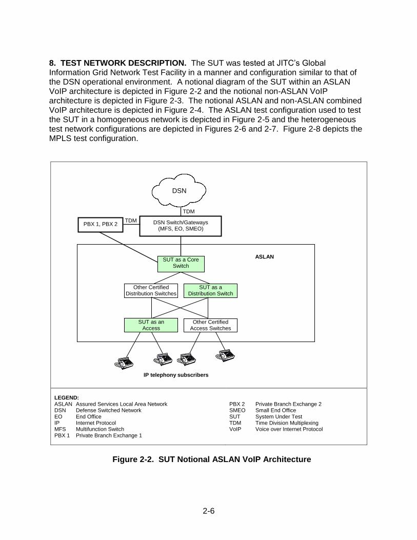
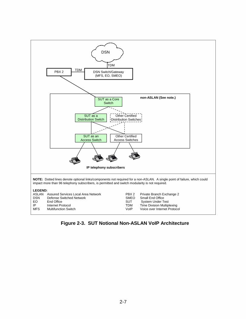
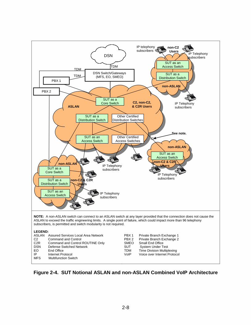
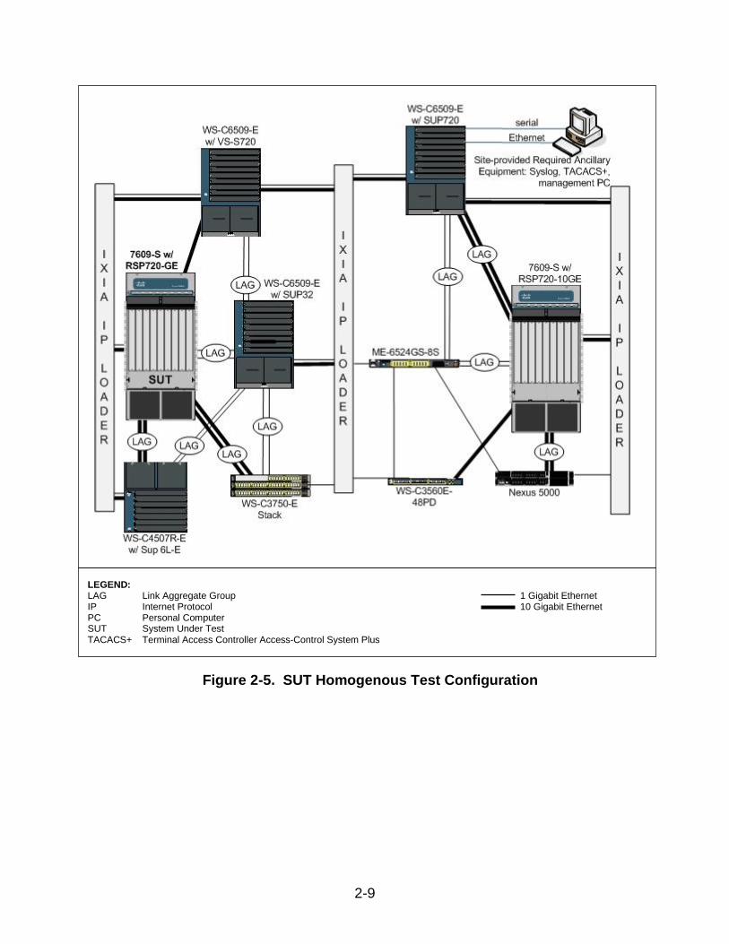
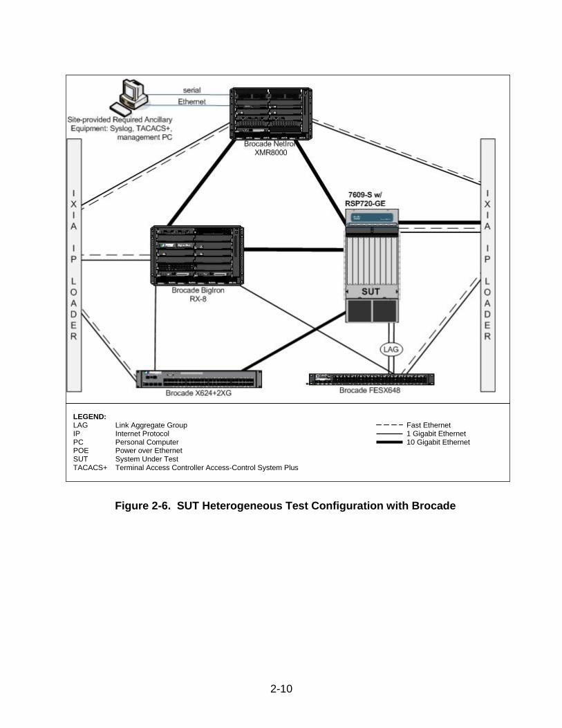
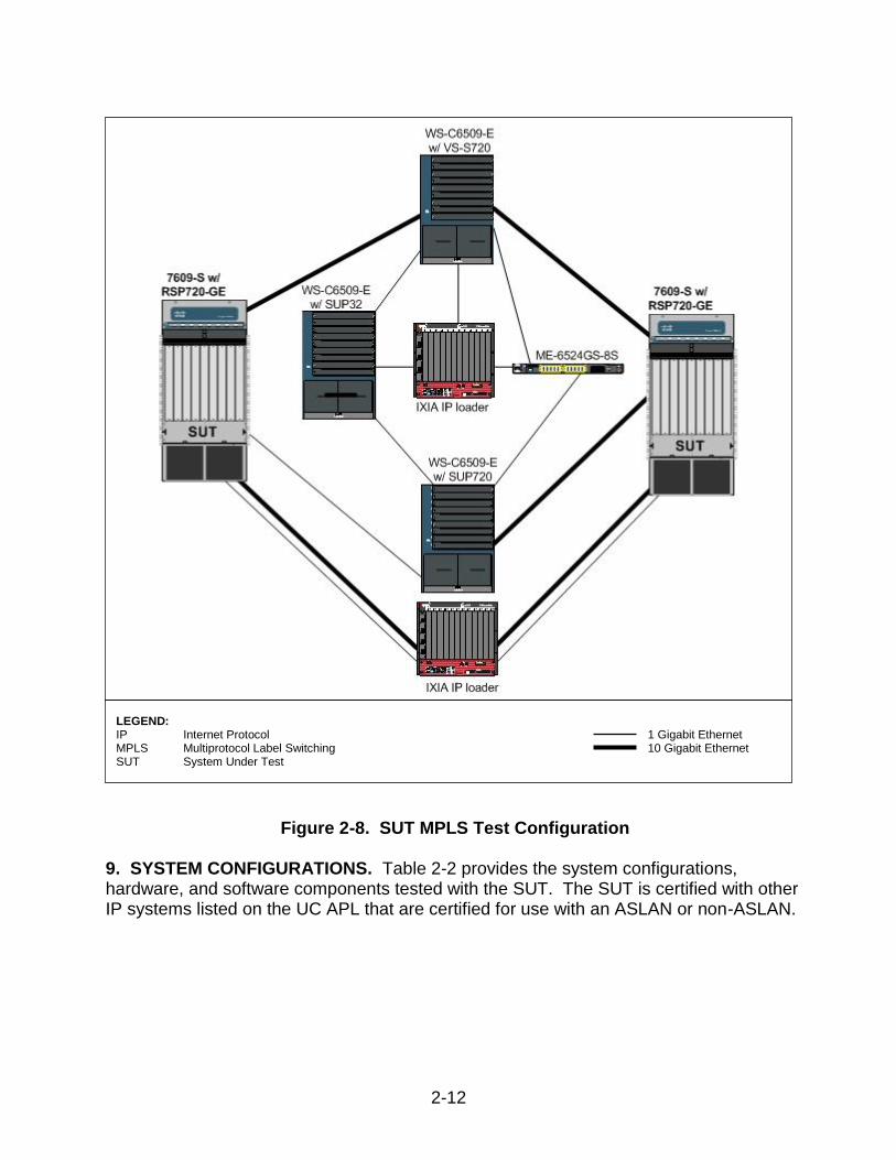
8. TEST NETWORK DESCRIPTION. The SUT was tested at JITC’s Global Information Grid Network Test Facility in a manner and configuration similar to that of the DSN operational environment. A notional diagram of the SUT within an ASLAN VoIP architecture is depicted in Figure 2-2 and the notional non-ASLAN VoIP architecture is depicted in Figure 2-3. The notional ASLAN and non-ASLAN combined VoIP architecture is depicted in Figure 2-4. The ASLAN test configuration used to test the SUT in a homogeneous network is depicted in Figure 2-5 and the heterogeneous test network configurations are depicted in Figures 2-6 and 2-7. Figure 2-8 depicts the MPLS test configuration.
LEGEND: ASLAN Assured Services Local Area Network DSN Defense Switched Network EO End Office IP Internet Protocol MFS Multifunction Switch PBX 1 Private Branch Exchange 1
PBX 2 Private Branch Exchange 2 SMEO Small End Office SUT System Under Test TDM Time Division Multiplexing VoIP Voice over Internet Protocol
Figure 2-2. SUT Notional ASLAN VoIP Architecture
Other Certified Distribution Switches
Switches
Other Certified Access Switches
Switches
SUT as an Access Switch
SUT as a Distribution Switch
DSN
ASLAN SUT as a Core
Switch
Telephone Telephone Telephone Telephone Telephone Telephone
Telephone Telephone
IP telephony subscribers
DSN Switch/Gateways (MFS, EO, SMEO)
PBX 1, PBX 2 TDM
TDM
2-7
NOTE: Dotted lines denote optional links/components not required for a non-ASLAN. A single point of failure, which could impact more than 96 telephony subscribers, is permitted and switch modularity is not required. LEGEND: ASLAN Assured Services Local Area Network DSN Defense Switched Network EO End Office IP Internet Protocol MFS Multifunction Switch
PBX 2 Private Branch Exchange 2 SMEO Small End Office SUT System Under Test TDM Time Division Multiplexing VoIP Voice over Internet Protocol
Figure 2-3. SUT Notional Non-ASLAN VoIP Architecture
SUT as a Distribution Switch
Other Certified Access Switches
Switch
SUT as an Access Switch
Other Certified Distribution Switches
DSN
non-ASLAN (See note.) SUT as a Core
Switch
Telephone Telephone Telephone Telephone Telephone Telephone
Telephone Telephone
IP telephony subscribers
DSN Switch/Gateway (MFS, EO, SMEO)
PBX 2 TDM
TDM
2-8
NOTE: A non-ASLAN switch can connect to an ASLAN switch at any layer provided that the connection does not cause the ASLAN to exceed the traffic engineering limits. A single point of failure, which could impact more than 96 telephony subscribers, is permitted and switch modularity is not required. LEGEND: ASLAN Assured Services Local Area Network C2 Command and Control C2R Command and Control ROUTINE Only DSN Defense Switched Network EO End Office IP Internet Protocol MFS Multifunction Switch
PBX 1 Private Branch Exchange 1 PBX 2 Private Branch Exchange 2 SMEO Small End Office SUT System Under Test TDM Time Division Multiplexing VoIP Voice over Internet Protocol
Figure 2-4. SUT Notional ASLAN and non-ASLAN Combined VoIP Architecture
Other Certified Access Switches
Switch
SUT as an Access Switch
Other Certified Distribution Switches
Router/Switch
SUT as a Core Switch
Telephone Telephone Telephone Telephone Telephone Telephone Telephone Telephone
C2, non-C2,
& C2R Users
DSN Switch/Gateways (MFS, EO, SMEO)
DSN
TDM
TDM
Telephone Telephone Telephone
PBX 1
non-C2 & C2R
Users
SUT as an Access Switch
non-ASLAN
Telephone
Telephone
Telephone
SUT as a Distribution Switch
non-C2
Users
Telephone Telephone Telephone Telephone
Telephone Telephone
Telephone Telephone
non-C2 & C2R
Users
SUT as a Distribution Switch
non-ASLAN
See note.
non-ASLAN
IP telephony subscribers
IP Telephony subscribers
IP Telephony subscribers
IP Telephony subscribers
IP Telephony subscribers
IP Telephony subscribers ASLAN
SUT as an Access Switch
SUT as a Distribution Switch
SUT as an
Access Switch
SUT as a Core Switch
PBX 2
TDM
2-9
Figure 2-5. SUT Homogenous Test Configuration
LEGEND: LAG Link Aggregate Group 1 Gigabit Ethernet IP Internet Protocol 10 Gigabit Ethernet PC Personal Computer SUT System Under Test TACACS+ Terminal Access Controller Access-Control System Plus
2-10
Figure 2-6. SUT Heterogeneous Test Configuration with Brocade
LEGEND: LAG Link Aggregate Group Fast Ethernet IP Internet Protocol 1 Gigabit Ethernet PC Personal Computer 10 Gigabit Ethernet POE Power over Ethernet SUT System Under Test TACACS+ Terminal Access Controller Access-Control System Plus
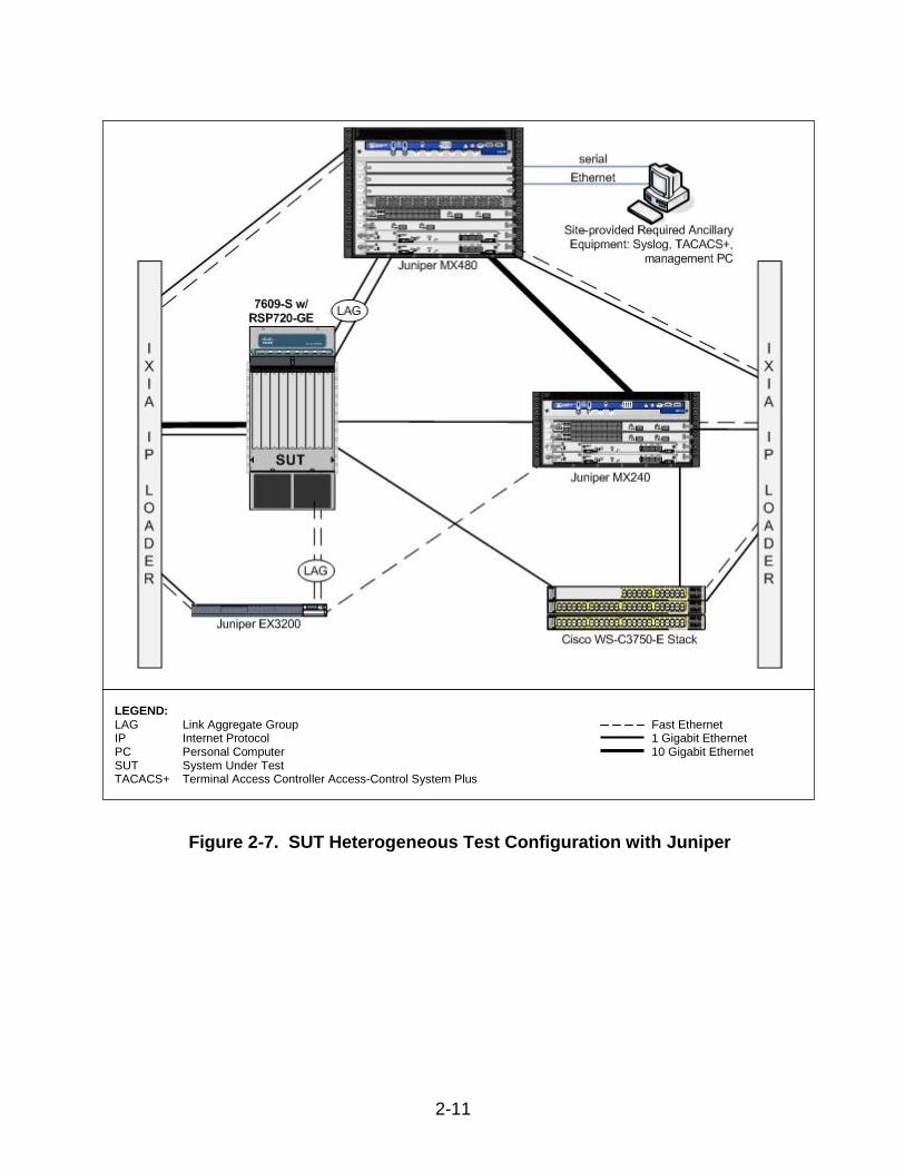
2-11
Figure 2-7. SUT Heterogeneous Test Configuration with Juniper
LEGEND: LAG Link Aggregate Group Fast Ethernet IP Internet Protocol 1 Gigabit Ethernet PC Personal Computer 10 Gigabit Ethernet SUT System Under Test TACACS+ Terminal Access Controller Access-Control System Plus
2-12
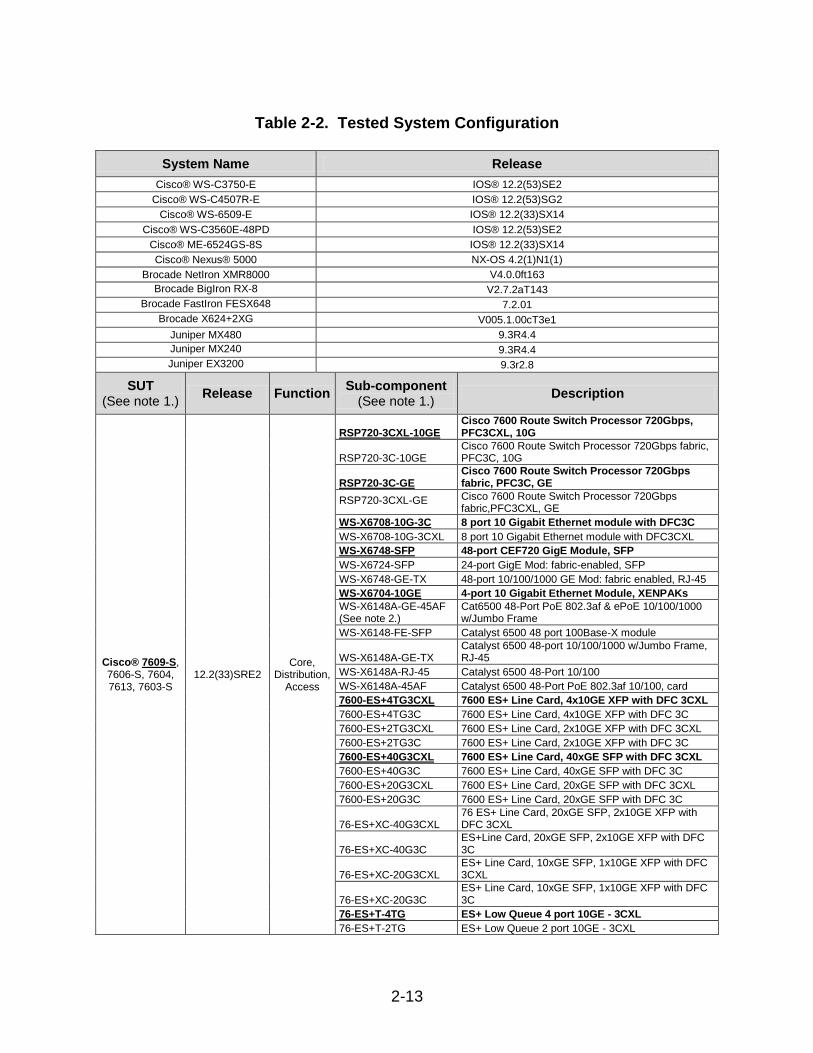
Figure 2-8. SUT MPLS Test Configuration 9. SYSTEM CONFIGURATIONS. Table 2-2 provides the system configurations, hardware, and software components tested with the SUT. The SUT is certified with other IP systems listed on the UC APL that are certified for use with an ASLAN or non-ASLAN.
LEGEND: IP Internet Protocol 1 Gigabit Ethernet MPLS Multiprotocol Label Switching 10 Gigabit Ethernet SUT System Under Test
2-13
Table 2-2. Tested System Configuration
System Name Release
Cisco® WS-C3750-E IOS® 12.2(53)SE2
Cisco® WS-C4507R-E IOS® 12.2(53)SG2
Cisco® WS-6509-E IOS® 12.2(33)SX14
Cisco® WS-C3560E-48PD IOS® 12.2(53)SE2
Cisco® ME-6524GS-8S IOS® 12.2(33)SX14
Cisco® Nexus® 5000 NX-OS 4.2(1)N1(1)
Brocade NetIron XMR8000 V4.0.0ft163 Brocade BigIron RX-8 V2.7.2aT143
Brocade FastIron FESX648 7.2.01
Brocade X624+2XG V005.1.00cT3e1
Juniper MX480 9.3R4.4 Juniper MX240 9.3R4.4 Juniper EX3200 9.3r2.8
SUT (See note 1.)
Release Function Sub-component
(See note 1.) Description
Cisco® 7609-S, 7606-S, 7604, 7613, 7603-S
12.2(33)SRE2 Core,
Distribution, Access
RSP720-3CXL-10GE Cisco 7600 Route Switch Processor 720Gbps, PFC3CXL, 10G
RSP720-3C-10GE Cisco 7600 Route Switch Processor 720Gbps fabric, PFC3C, 10G
RSP720-3C-GE Cisco 7600 Route Switch Processor 720Gbps fabric, PFC3C, GE
RSP720-3CXL-GE Cisco 7600 Route Switch Processor 720Gbps fabric,PFC3CXL, GE
WS-X6708-10G-3C 8 port 10 Gigabit Ethernet module with DFC3C
WS-X6708-10G-3CXL 8 port 10 Gigabit Ethernet module with DFC3CXL
WS-X6748-SFP 48-port CEF720 GigE Module, SFP
WS-X6724-SFP 24-port GigE Mod: fabric-enabled, SFP
WS-X6748-GE-TX 48-port 10/100/1000 GE Mod: fabric enabled, RJ-45
WS-X6704-10GE 4-port 10 Gigabit Ethernet Module, XENPAKs
WS-X6148A-GE-45AF (See note 2.)
Cat6500 48-Port PoE 802.3af & ePoE 10/100/1000 w/Jumbo Frame
WS-X6148-FE-SFP Catalyst 6500 48 port 100Base-X module
WS-X6148A-GE-TX Catalyst 6500 48-port 10/100/1000 w/Jumbo Frame, RJ-45
WS-X6148A-RJ-45 Catalyst 6500 48-Port 10/100
WS-X6148A-45AF Catalyst 6500 48-Port PoE 802.3af 10/100, card
7600-ES+4TG3CXL 7600 ES+ Line Card, 4x10GE XFP with DFC 3CXL
7600-ES+4TG3C 7600 ES+ Line Card, 4x10GE XFP with DFC 3C
7600-ES+2TG3CXL 7600 ES+ Line Card, 2x10GE XFP with DFC 3CXL
7600-ES+2TG3C 7600 ES+ Line Card, 2x10GE XFP with DFC 3C
7600-ES+40G3CXL 7600 ES+ Line Card, 40xGE SFP with DFC 3CXL
7600-ES+40G3C 7600 ES+ Line Card, 40xGE SFP with DFC 3C
7600-ES+20G3CXL 7600 ES+ Line Card, 20xGE SFP with DFC 3CXL
7600-ES+20G3C 7600 ES+ Line Card, 20xGE SFP with DFC 3C
76-ES+XC-40G3CXL 76 ES+ Line Card, 20xGE SFP, 2x10GE XFP with DFC 3CXL
76-ES+XC-40G3C ES+Line Card, 20xGE SFP, 2x10GE XFP with DFC 3C
76-ES+XC-20G3CXL ES+ Line Card, 10xGE SFP, 1x10GE XFP with DFC 3CXL
76-ES+XC-20G3C ES+ Line Card, 10xGE SFP, 1x10GE XFP with DFC 3C
76-ES+T-4TG ES+ Low Queue 4 port 10GE - 3CXL
76-ES+T-2TG ES+ Low Queue 2 port 10GE - 3CXL
2-14
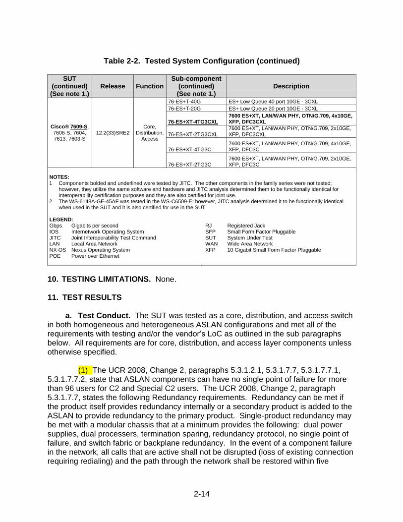
Table 2-2. Tested System Configuration (continued)
SUT (continued) (See note 1.)
Release Function Sub-component
(continued) (See note 1.)
Description
Cisco® 7609-S, 7606-S, 7604, 7613, 7603-S
12.2(33)SRE2 Core,
Distribution, Access
76-ES+T-40G ES+ Low Queue 40 port 10GE - 3CXL
76-ES+T-20G ES+ Low Queue 20 port 10GE - 3CXL
76-ES+XT-4TG3CXL 7600 ES+XT, LAN/WAN PHY, OTN/G.709, 4x10GE, XFP, DFC3CXL
76-ES+XT-2TG3CXL 7600 ES+XT, LAN/WAN PHY, OTN/G.709, 2x10GE, XFP, DFC3CXL
76-ES+XT-4TG3C 7600 ES+XT, LAN/WAN PHY, OTN/G.709, 4x10GE, XFP, DFC3C
76-ES+XT-2TG3C 7600 ES+XT, LAN/WAN PHY, OTN/G.709, 2x10GE, XFP, DFC3C
NOTES: 1 Components bolded and underlined were tested by JITC. The other components in the family series were not tested;
however, they utilize the same software and hardware and JITC analysis determined them to be functionally identical for interoperability certification purposes and they are also certified for joint use.
2 The WS-6148A-GE-45AF was tested in the WS-C6509-E; however, JITC analysis determined it to be functionally identical when used in the SUT and it is also certified for use in the SUT.
LEGEND: Gbps Gigabits per second IOS Internetwork Operating System JITC Joint Interoperability Test Command LAN Local Area Network NX-OS Nexus Operating System POE Power over Ethernet
RJ Registered Jack SFP Small Form Factor Pluggable SUT System Under Test WAN Wide Area Network XFP 10 Gigabit Small Form Factor Pluggable
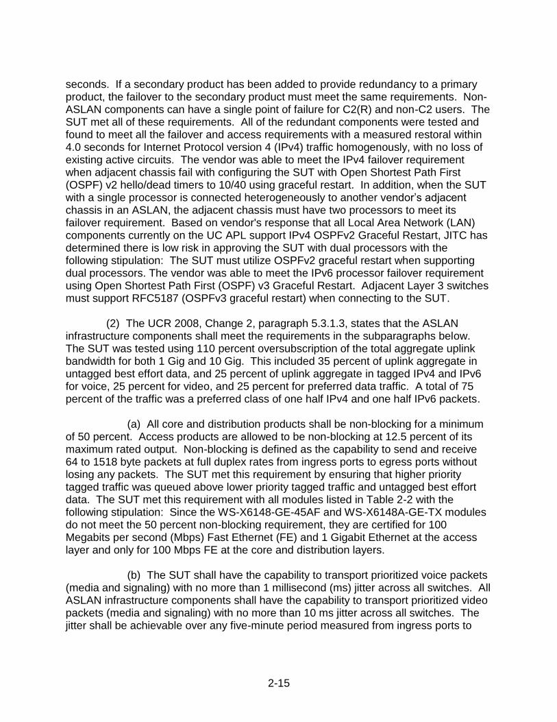
10. TESTING LIMITATIONS. None. 11. TEST RESULTS
a. Test Conduct. The SUT was tested as a core, distribution, and access switch in both homogeneous and heterogeneous ASLAN configurations and met all of the requirements with testing and/or the vendor’s LoC as outlined in the sub paragraphs below. All requirements are for core, distribution, and access layer components unless otherwise specified.
(1) The UCR 2008, Change 2, paragraphs 5.3.1.2.1, 5.3.1.7.7, 5.3.1.7.7.1, 5.3.1.7.7.2, state that ASLAN components can have no single point of failure for more than 96 users for C2 and Special C2 users. The UCR 2008, Change 2, paragraph 5.3.1.7.7, states the following Redundancy requirements. Redundancy can be met if the product itself provides redundancy internally or a secondary product is added to the ASLAN to provide redundancy to the primary product. Single-product redundancy may be met with a modular chassis that at a minimum provides the following: dual power supplies, dual processers, termination sparing, redundancy protocol, no single point of failure, and switch fabric or backplane redundancy. In the event of a component failure in the network, all calls that are active shall not be disrupted (loss of existing connection requiring redialing) and the path through the network shall be restored within five
2-15
seconds. If a secondary product has been added to provide redundancy to a primary product, the failover to the secondary product must meet the same requirements. Non-ASLAN components can have a single point of failure for C2(R) and non-C2 users. The SUT met all of these requirements. All of the redundant components were tested and found to meet all the failover and access requirements with a measured restoral within 4.0 seconds for Internet Protocol version 4 (IPv4) traffic homogenously, with no loss of existing active circuits. The vendor was able to meet the IPv4 failover requirement when adjacent chassis fail with configuring the SUT with Open Shortest Path First (OSPF) v2 hello/dead timers to 10/40 using graceful restart. In addition, when the SUT with a single processor is connected heterogeneously to another vendor’s adjacent chassis in an ASLAN, the adjacent chassis must have two processors to meet its failover requirement. Based on vendor's response that all Local Area Network (LAN) components currently on the UC APL support IPv4 OSPFv2 Graceful Restart, JITC has determined there is low risk in approving the SUT with dual processors with the following stipulation: The SUT must utilize OSPFv2 graceful restart when supporting dual processors. The vendor was able to meet the IPv6 processor failover requirement using Open Shortest Path First (OSPF) v3 Graceful Restart. Adjacent Layer 3 switches must support RFC5187 (OSPFv3 graceful restart) when connecting to the SUT.
(2) The UCR 2008, Change 2, paragraph 5.3.1.3, states that the ASLAN infrastructure components shall meet the requirements in the subparagraphs below. The SUT was tested using 110 percent oversubscription of the total aggregate uplink bandwidth for both 1 Gig and 10 Gig. This included 35 percent of uplink aggregate in untagged best effort data, and 25 percent of uplink aggregate in tagged IPv4 and IPv6 for voice, 25 percent for video, and 25 percent for preferred data traffic. A total of 75 percent of the traffic was a preferred class of one half IPv4 and one half IPv6 packets.
(a) All core and distribution products shall be non-blocking for a minimum of 50 percent. Access products are allowed to be non-blocking at 12.5 percent of its maximum rated output. Non-blocking is defined as the capability to send and receive 64 to 1518 byte packets at full duplex rates from ingress ports to egress ports without losing any packets. The SUT met this requirement by ensuring that higher priority tagged traffic was queued above lower priority tagged traffic and untagged best effort data. The SUT met this requirement with all modules listed in Table 2-2 with the following stipulation: Since the WS-X6148-GE-45AF and WS-X6148A-GE-TX modules do not meet the 50 percent non-blocking requirement, they are certified for 100 Megabits per second (Mbps) Fast Ethernet (FE) and 1 Gigabit Ethernet at the access layer and only for 100 Mbps FE at the core and distribution layers.
(b) The SUT shall have the capability to transport prioritized voice packets (media and signaling) with no more than 1 millisecond (ms) jitter across all switches. All ASLAN infrastructure components shall have the capability to transport prioritized video packets (media and signaling) with no more than 10 ms jitter across all switches. The jitter shall be achievable over any five-minute period measured from ingress ports to
2-16
egress ports under congested conditions. The SUT met this requirement with a measured jitter of 1 ms for voice and video packets.
(c) All core and distribution products shall have the capability to transport
prioritized voice and video packets (media and signaling) with no more than 0.015 percent packet loss. Access products shall have the capability to transport prioritized voice and video packets with no more than 0.05 percent packet loss. The packet loss shall be achievable over any five-minute period measured from ingress ports to egress ports under congested conditions. The SUT met this requirement with a measured packet loss of 0.00 percent for voice and video packets.
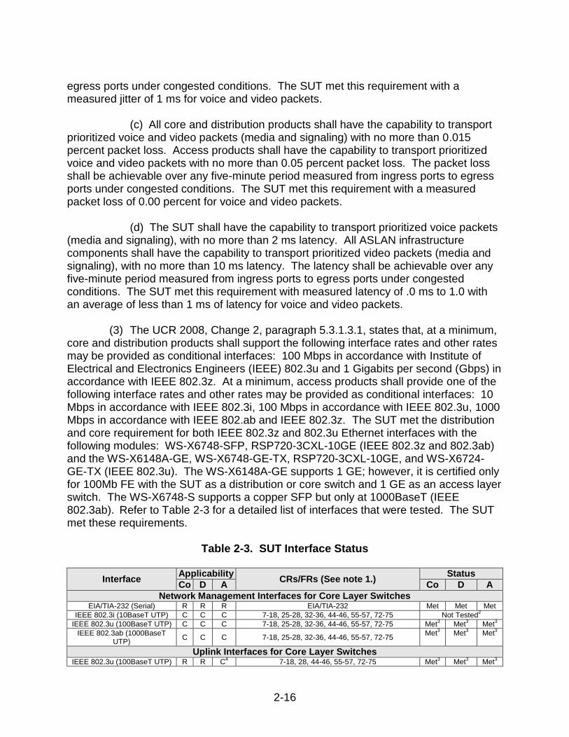
(d) The SUT shall have the capability to transport prioritized voice packets (media and signaling), with no more than 2 ms latency. All ASLAN infrastructure components shall have the capability to transport prioritized video packets (media and signaling), with no more than 10 ms latency. The latency shall be achievable over any five-minute period measured from ingress ports to egress ports under congested conditions. The SUT met this requirement with measured latency of .0 ms to 1.0 with an average of less than 1 ms of latency for voice and video packets. (3) The UCR 2008, Change 2, paragraph 5.3.1.3.1, states that, at a minimum, core and distribution products shall support the following interface rates and other rates may be provided as conditional interfaces: 100 Mbps in accordance with Institute of Electrical and Electronics Engineers (IEEE) 802.3u and 1 Gigabits per second (Gbps) in accordance with IEEE 802.3z. At a minimum, access products shall provide one of the following interface rates and other rates may be provided as conditional interfaces: 10 Mbps in accordance with IEEE 802.3i, 100 Mbps in accordance with IEEE 802.3u, 1000 Mbps in accordance with IEEE 802.ab and IEEE 802.3z. The SUT met the distribution and core requirement for both IEEE 802.3z and 802.3u Ethernet interfaces with the following modules: WS-X6748-SFP, RSP720-3CXL-10GE (IEEE 802.3z and 802.3ab) and the WS-X6148A-GE, WS-X6748-GE-TX, RSP720-3CXL-10GE, and WS-X6724-GE-TX (IEEE 802.3u). The WS-X6148A-GE supports 1 GE; however, it is certified only for 100Mb FE with the SUT as a distribution or core switch and 1 GE as an access layer switch. The WS-X6748-S supports a copper SFP but only at 1000BaseT (IEEE 802.3ab). Refer to Table 2-3 for a detailed list of interfaces that were tested. The SUT met these requirements.
Table 2-3. SUT Interface Status
Interface Applicability
CRs/FRs (See note 1.) Status
Co D A Co D A
Network Management Interfaces for Core Layer Switches EIA/TIA-232 (Serial) R R R EIA/TIA-232 Met Met Met
IEEE 802.3i (10BaseT UTP) C C C 7-18, 25-28, 32-36, 44-46, 55-57, 72-75 Not Tested2
IEEE 802.3u (100BaseT UTP) C C C 7-18, 25-28, 32-36, 44-46, 55-57, 72-75 Met3 Met
3 Met3
IEEE 802.3ab (1000BaseT UTP)
C C C 7-18, 25-28, 32-36, 44-46, 55-57, 72-75 Met
3 Met3 Met
3
Uplink Interfaces for Core Layer Switches IEEE 802.3u (100BaseT UTP) R R C
4 7-18, 28, 44-46, 55-57, 72-75 Met
3 Met3 Met
3
2-17
IEEE 802.3u (100BaseFX) C C C4 10-18, 28, 44-46, 55-57, 72-75 Met
3 Met3 Met
3 IEEE 802.3ab (1000BaseT
UTP) C C C
4
7-18, 28, 44-46, 55-57, 72-75 Met3 Met
3 Met3
IEEE 802.3z (1000BaseX Fiber)
R R C4
10-18, 28, 44-46, 55-57, 72-75 Met3 Met
3 Met3
IEEE 802.3ae (10GBaseX) C C C4 10-18, 28, 44-46, 55-57, 72-75 Met
3 Met3 Met
3 Access Interfaces for Core Layer Switches
IEEE 802.3i (10BaseT UTP) C C C4 7-18, 28, 44-46, 55-57, 72-75 Met
3 Met3 Met
3 IEEE 802.3u (100BaseT UTP) R R C
4 7-18, 28, 44-46, 55-57, 72-75 Met
3 Met3 Met
3 IEEE 802.3u (100BaseFX) C C C
4 10-18, 28, 44-46, 55-57, 72-75 Met
3 Met3 Met
3 IEEE 802.3ab (1000BaseT
UTP) C C C
4
7-18, 28, 44-46, 55-57, 72-75 Met3 Met
3 Met3
IEEE 802.3z (1000BaseX Fiber)
R R C4
10-18, 28, 44-46, 55-57, 72-75 Met3 Met
3 Met3
Generic Requirements for all Interfaces
Generic Requirements not associated with specific
interfaces R R R 30-32, 35, 36, 40, 69-71 Met Met Met
DoD IPv6 Profile Requirements R R R UCR Section 5.3.5.5 Met Met Met Security R R R 79-82 Met
5 Met
5 Met
5
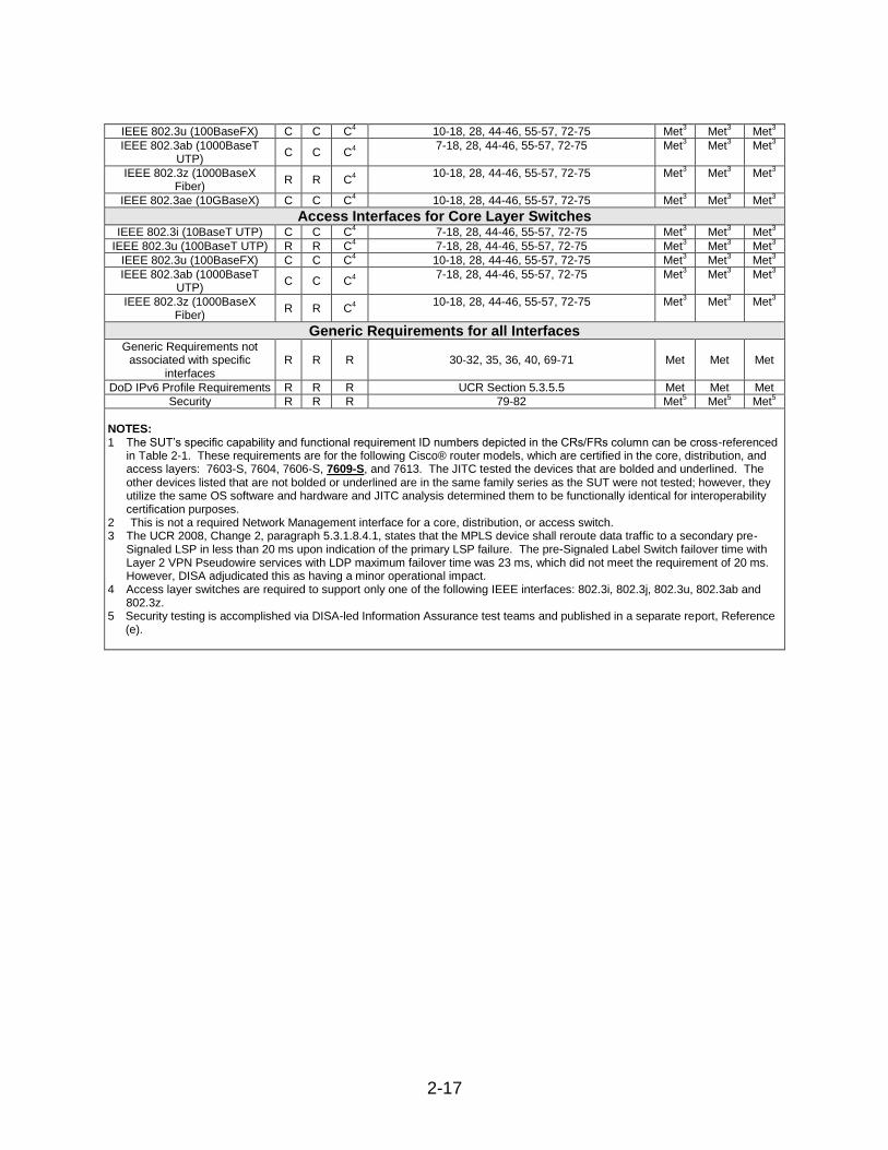
NOTES: 1 The SUT’s specific capability and functional requirement ID numbers depicted in the CRs/FRs column can be cross-referenced
in Table 2-1. These requirements are for the following Cisco® router models, which are certified in the core, distribution, and access layers: 7603-S, 7604, 7606-S, 7609-S, and 7613. The JITC tested the devices that are bolded and underlined. The other devices listed that are not bolded or underlined are in the same family series as the SUT were not tested; however, they utilize the same OS software and hardware and JITC analysis determined them to be functionally identical for interoperability certification purposes.
2 This is not a required Network Management interface for a core, distribution, or access switch. 3 The UCR 2008, Change 2, paragraph 5.3.1.8.4.1, states that the MPLS device shall reroute data traffic to a secondary pre-
Signaled LSP in less than 20 ms upon indication of the primary LSP failure. The pre-Signaled Label Switch failover time with Layer 2 VPN Pseudowire services with LDP maximum failover time was 23 ms, which did not meet the requirement of 20 ms. However, DISA adjudicated this as having a minor operational impact.
4 Access layer switches are required to support only one of the following IEEE interfaces: 802.3i, 802.3j, 802.3u, 802.3ab and 802.3z.
5 Security testing is accomplished via DISA-led Information Assurance test teams and published in a separate report, Reference (e).
2-18
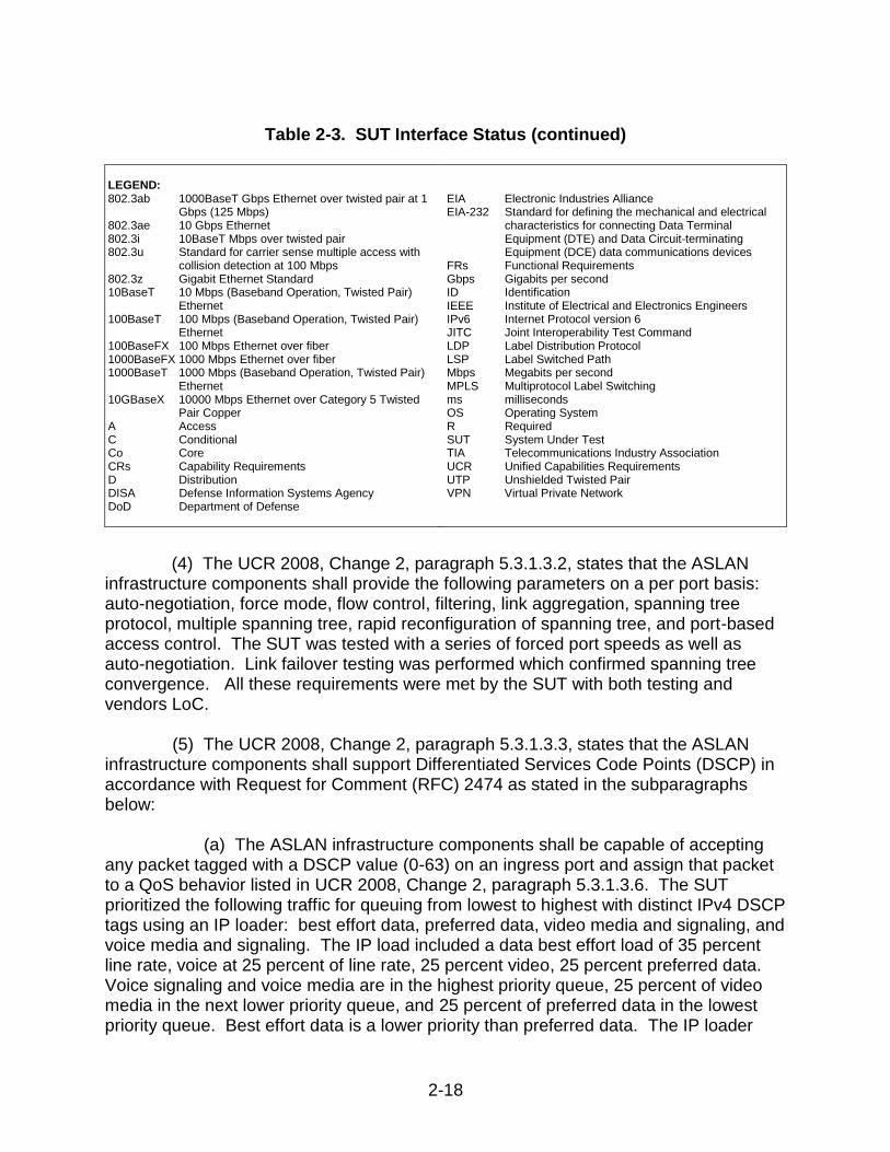
Table 2-3. SUT Interface Status (continued) LEGEND: 802.3ab 1000BaseT Gbps Ethernet over twisted pair at 1
Gbps (125 Mbps) 802.3ae 10 Gbps Ethernet 802.3i 10BaseT Mbps over twisted pair 802.3u Standard for carrier sense multiple access with
collision detection at 100 Mbps 802.3z Gigabit Ethernet Standard 10BaseT 10 Mbps (Baseband Operation, Twisted Pair)
Ethernet 100BaseT 100 Mbps (Baseband Operation, Twisted Pair)
Ethernet 100BaseFX 100 Mbps Ethernet over fiber 1000BaseFX 1000 Mbps Ethernet over fiber 1000BaseT 1000 Mbps (Baseband Operation, Twisted Pair)
Ethernet 10GBaseX 10000 Mbps Ethernet over Category 5 Twisted
Pair Copper A Access C Conditional Co Core CRs Capability Requirements D Distribution DISA Defense Information Systems Agency DoD Department of Defense
EIA Electronic Industries Alliance EIA-232 Standard for defining the mechanical and electrical
characteristics for connecting Data Terminal Equipment (DTE) and Data Circuit-terminating Equipment (DCE) data communications devices
FRs Functional Requirements Gbps Gigabits per second ID Identification IEEE Institute of Electrical and Electronics Engineers IPv6 Internet Protocol version 6 JITC Joint Interoperability Test Command LDP Label Distribution Protocol LSP Label Switched Path Mbps Megabits per second MPLS Multiprotocol Label Switching ms milliseconds OS Operating System R Required SUT System Under Test TIA Telecommunications Industry Association UCR Unified Capabilities Requirements UTP Unshielded Twisted Pair VPN Virtual Private Network
(4) The UCR 2008, Change 2, paragraph 5.3.1.3.2, states that the ASLAN infrastructure components shall provide the following parameters on a per port basis: auto-negotiation, force mode, flow control, filtering, link aggregation, spanning tree protocol, multiple spanning tree, rapid reconfiguration of spanning tree, and port-based access control. The SUT was tested with a series of forced port speeds as well as auto-negotiation. Link failover testing was performed which confirmed spanning tree convergence. All these requirements were met by the SUT with both testing and vendors LoC. (5) The UCR 2008, Change 2, paragraph 5.3.1.3.3, states that the ASLAN infrastructure components shall support Differentiated Services Code Points (DSCP) in accordance with Request for Comment (RFC) 2474 as stated in the subparagraphs below:
(a) The ASLAN infrastructure components shall be capable of accepting any packet tagged with a DSCP value (0-63) on an ingress port and assign that packet to a QoS behavior listed in UCR 2008, Change 2, paragraph 5.3.1.3.6. The SUT prioritized the following traffic for queuing from lowest to highest with distinct IPv4 DSCP tags using an IP loader: best effort data, preferred data, video media and signaling, and voice media and signaling. The IP load included a data best effort load of 35 percent line rate, voice at 25 percent of line rate, 25 percent video, 25 percent preferred data. Voice signaling and voice media are in the highest priority queue, 25 percent of video media in the next lower priority queue, and 25 percent of preferred data in the lowest priority queue. Best effort data is a lower priority than preferred data. The IP loader
2-19
recorded that the higher prioritized traffic was properly queued by the SUT above lower prioritized best effort traffic. In addition, it was verified that the SUT can assign any DSCP value from 0-63 for each type of traffic, which met this requirement.
(b) The ASLAN infrastructure components shall be capable of accepting
any packet tagged with a DSCP value (0-63) on an ingress port and reassign that packet to any new DSCP value (0-63). Current DSCP values are provided in UCR 2008, Change 2, paragraph 5.3.3.3.2. The SUT met this requirement with the vendor’s LoC.
(c) The ASLAN infrastructure components must be able to support the
prioritization of aggregate service classes with queuing according to UCR 2008, Change 2, paragraph 5.3.1.3.6. The SUT prioritized the following traffic for queuing from lowest to highest with distinct IPv6 service class tags using an IP loader: best effort data, preferred data, video media and signaling, and voice media and signaling. The IP load included a data best effort load of 35 percent line rate, voice at 25 percent of line rate, 25 percent video, and 25 percent preferred data. Voice signaling and voice media are in the highest priority queue, 25 percent of video media in the next lower priority queue, and 25 percent of preferred data in the lowest priority queue. Best effort data is a lower priority than preferred data. The IP loader recorded that the higher prioritized traffic was properly queued by the SUT above lower prioritized best effort traffic. In addition it was verified that the SUT can assign any IPv6 traffic class value from 0-63 for each type of traffic, which met this requirement.
(d) The ASLAN infrastructure components may support the 3-bit user
priority field of the IEEE 802.1Q 2-byte Tag Control Information (TCI) field. Default values are provided in UCR 2008, Change 2, Table 5.3.1-4. If provided, the following Class of Service (CoS) requirements apply: The ASLAN infrastructure components shall be capable of accepting any frame tagged with a user priority value (0-7) on an ingress port and assign that frame to a QoS behavior listed in UCR 2008, Change 2, paragraph 5.3.1.3.6. The ASLAN infrastructure components shall be capable of accepting any frame tagged with a user priority value (0-7) on an ingress port and reassign that frame to any new user priority value (0-7). The SUT met this requirement with the vendor’s LoC. (6) The UCR 2008, Change 2, paragraph 5.3.1.3.4, states that the ASLAN infrastructure components shall be capable of the Virtual LAN (VLAN) capabilities in accordance with IEEE 802.1Q. The SUT was configured with a preset VLAN ID tag using the IP loader. This load was captured at the egress and ingress to insure that the SUT was properly assigning the VLAN ID in the proper VLAN and not modifying or misplacing the assigned VLAN traffic in any way. In addition, the SUT has the ability to assign any VLAN ID any value from 0 through 4096. The SUT met this requirement with both testing and vendor’s LoC.
2-20
(7) The UCR 2008, Change 2, paragraph 5.3.1.3.5, states that the ASLAN infrastructure components shall meet the Department of Defense Information Technology Standards Registry (DISR) protocol requirements for IPv4 and IPv6. The SUT prioritized the following traffic for queuing from lowest to highest with distinct IPv4 DSCP tags and IPv6 service class tags using an IP loader: best effort data, preferred data, video media and signaling, and voice media and signaling. The IP load included a data best effort load of 35 percent line rate, voice at 25 percent of line rate, 25 percent video, and 25 percent preferred data. Voice signaling and voice media are in the highest priority queue, 25 percent of video media in the next lower priority queue, and 25 percent of preferred data in the lowest priority queue. Best effort data is a lower priority than preferred data. The IP loader recorded that the higher prioritized traffic was properly queued by the SUT above lower prioritized best effort traffic. It was verified that the SUT can assign any IPv4 DSCP or IPv6 traffic class value from 0-63 for each type of traffic which met this requirement. The IPv6 RFC DISR profile requirements were also met with the vendor’s LoC. (8) The UCR 2008, Change 2, paragraph 5.3.1.3.6, states that the ASLAN infrastructure components shall be capable of providing the following QoS features: (a) Provide a minimum of four queues. The SUT was tested with a four-queue model, and is certified with a four-queue configuration. (b) Assign any tagged session to any of the queues. The SUT met this requirement with both testing and vendor’s LoC. (c) Support Differentiated Services (DiffServ) per hop behaviors (PHBs) in accordance with RFCs 2472, 2597, 2598, and 3246. The SUT met this requirement with both testing and vendor’s LoC. (d) Support, at a minimum, one of the following: Weighted Fair Queuing (WFQ) in accordance with RFC 3662, Priority Queuing (PQ) in accordance with RFC 1046, or Class-Based WFQ in accordance with RFC 3366. The SUT supports all three types of queuing. WFQ queuing types were met through testing and Class-Based WFQ and PQ were met with the vendor’s LoC. (e) All queues shall be capable of having bandwidth assigned or percentage of traffic. The SUT prioritized the following traffic for queuing from lowest to highest with distinct IPv4 DSCP tags and IPv6 service class tags using an IP loader: best effort data, preferred data, video media and signaling, and voice media and signaling. The IP load included a data best effort load of 35 percent line rate, voice at 25 percent of line rate, 25 percent video, and 25 percent preferred data. Voice signaling and voice media are in the highest priority queue, 25 percent of video media in the next lower priority queue, and 25 percent of preferred data in the lowest priority queue. Best effort data is a lower priority than preferred data. The IP loader recorded that the higher prioritized traffic was properly queued by the SUT above lower prioritized best effort
2-21
traffic. Subsequently, the IP loader was reconfigured to increase the video traffic to 35 percent of line rate to ensure the SUT only allowed 25 percent throughput of the video traffic. The captured video throughput measured by the IP loader was 25.2 percent of the line rate, which met this requirement. In addition to testing, this requirement was met with the vendor’s LoC. (9 ) The UCR 2008, Change 2, paragraph 5.3.1.3.7, states that the ASLAN infrastructure components shall be capable of providing the following Network Monitoring features: (a) Simple Network Management Protocol (SNMP) in accordance with RFCs 1157, 2206, 3410, 3411, 3412, 3413, and 3414. The SUT met this requirement through the vendor’s LoC and testing using an SNMP management tool, which was used to verify SNMP SETS, GETS, and TRAPS. (b) SNMP Traps in accordance with RFC 1215. The SUT met this requirement through testing and the vendor’s LoC. (c) Remote Monitoring (RMON) in accordance with RFC 2819. The SUT met this requirement with the vendor’s LoC. (d) Coexistence between Version 1, Version 2, and Version 3 of the Internet-Standard Network Management Framework in accordance with RFC 3584. The SUT met this requirement with the vendor’s LoC. (e) The Advanced Encryption Standard (AES) Cipher Algorithm in the SNMP User-based Security Model in accordance with RFC 3826. Security is tested by DISA-led Information Assurance test teams and published in a separate report, Reference (e). (10) The UCR 2008, Change 2, paragraph 5.3.1.3.9, states that all switches meet Product Requirements in accordance with UCR 2008, Change 2, Table 5.3.1-5. The SUT met the requirements listed in Table 5.3.1-5 as stipulated throughout this document by testing and/or vendor LoC.
(11) The UCR 2008, Change 2, section 5.3.1.4, states that the ASLAN infrastructure components shall be capable of meeting the End-to-End (E2E) performance requirements for voice, video, and data services. The E2E performance across a LAN is measured from the traffic ingress point to the traffic egress port. The requirements are measured over any five-minute period under congested conditions. Congested condition is defined as 100 percent of link capacities (as defined by baseline traffic engineering (25 percent voice/signaling, 25 percent video, 25 percent preferred data, and 25 percent best effort traffic). The E2E requirements are ASLAN requirements. However, all of the E2E voice, video, and data services performance
2-22
requirements were met by the SUT when included within an ASLAN. Refer to paragraphs 11.b.(2)(b), 11.b.(2)(c), and 11.b.(2)(d).
(12) The UCR 2008, Change 2, section 5.3.1.6, states that LAN infrastructure components must meet the requirements in the subparagraphs below. Near Real Time (NRT) is defined as within five seconds of detecting the event, excluding transport time.
(a) LANs shall have the ability to perform remote network product
configuration/reconfiguration of objects that have existing Department of Defense (DoD) Global Information Grid (GIG) management capabilities. The Network Management System (NMS) shall report configuration change events in NRT, whether or not the change was authorized. The system shall report the success or failure of authorized configuration change attempts in NRT. The SUT met this requirement by responding in NRT of less than 1 second to the syslog server.
(b) LAN infrastructure components must provide metrics to the NMS to
allow them to make decisions on managing the network. The NMS shall have an automated Network Management (NM) capability to obtain the status of networks and associated assets in NRT 99 percent of the time (with 99.9 percent as an Objective Requirement). Specific metrics are defined in UCR 2008, Change 2, Sections 5.3.2.17 and 5.3.2.18. The SUT met this requirement by responding in NRT of less than 1 second 100 percent of the time.
(c) LAN components shall be capable of providing status changes 99
percent of the time (with 99.9 percent as an Objective Requirement) by means of an automated capability in NRT. An NMS will have an automated NM capability to obtain the status of networks and associated assets 99 percent of the time (with 99.9 percent as an Objective Requirement) in NRT. The NMS shall collect statistics and monitor bandwidth utilization, delay, jitter, and packet loss. The SUT met this requirement by responding in NRT of less than 1 second 100 percent of the time.
(d) LAN components shall be capable of providing SNMP alarm
indications to an NMS. The NMSs will have the NM capability to perform automated fault management of the network, to include problem detection, fault correction, fault isolation and diagnosis, problem tracking until corrective actions are completed, and historical archiving. Alarms will be correlated to eliminate those that are duplicate or false, initiate test, and perform diagnostics to isolate faults to a replaceable component. Alarms shall be reported as TRAPs via SNMP in NRT. More than 99.95 percent of alarms shall be reported in NRT. The SUT met this requirement by responding in NRT of less than 1 second 100 percent of the time using a Commercial Off the Shelf SNMP tool.
(e) An NMS will have the NM capability of automatically generating and
providing an integrated/ correlated presentation of network and all associated networks. The SUT met this requirement with the vendor’s LoC.
2-23
(13) The SUT met the conditional requirements of ASLAN MPLS. The SUT met the following requirements:
(a) The UCR 2008 Change 2, 5.3.1.8.4.1, states that an ASLAN product
that implements MPLS must still meet all the ASLAN requirements for jitter, latency, and packet loss. The addition of the MPLS protocol must not add to the overall measured performance characteristics with the following caveats: The MPLS device shall reroute data traffic to a secondary pre-Signaled Label Switched Path (LSP) in less than 20 ms upon indication of the primary LSP failure. The SUT supports MPLS and met the requirements with an average latency of .628, average jitter of 0.00 ms and packet loss of 0.00 percent, which met the requirements for IPv4 and IPv6.
(b) The UCR 2008, Change 2, 5.5.6.6, states that the NE shall act as an
MPLS Label Switching Router (LSR) by forwarding inbound labeled packets based on the contents of the packet MPLS header and performing label swapping (inbound packet label pop and outbound packet label push) as defined in RFC 3031. The SUT provided the proper label stack format and the proper operation of label push, swap, and pop requirements.
(c) The UCR 2008, Change 2, 5.3.1.8.4.1, states that the MPLS device shall reroute data traffic to a secondary pre-Signaled LSP in less than 20 ms upon indication of the primary LSP failure. The pre-Signaled Label Switch failover time with Layer 2 VPN Pseudowire services with Label Distribution Protocol (LDP) maximum failover time was 23 ms which did not meet the requirement of 20 ms. However, DISA adjudicated this as having a minor operational impact.
(d) The UCR 2008, Change 2, 5.3.1.8.4.1 (1), states that the ASLAN
Core and Distribution products that will be used to provide MPLS services must support the RFCs contained in Table 5.3.1-14. The SUT met the requirements via testing and vendor LOC.
(e) The UCR 2008, Change 2, 5.3.1.8.4.2, states that the MPLS supports
both Layer 2 VPNs and Layer 3 VPNs. A Layer 2 MPLS VPN, also known as L2VPN, is a point-to-point pseudo-wire service. An L2VPN can be used to replace existing physical links. The primary advantage of this MPLS VPN type is that it can replace an existing dedicated facility transparently without reconfiguration, and that it is completely agnostic to upper-layer protocols. A Layer 3 MPLS VPN, also known as L3VPN, combines enhanced routing signaling, MPLS traffic isolation, and router support for Virtual Routing/Forwarding (VRFs) to create an IP-based VPN. The SUT met this requirement.
(f) The UCR 2008, Change 2, 5.3.1.8.4.2.1, states that the ASLAN core
or distribution products will provide Layer 2 MPLS VPNs by supporting RFC 4762, “Virtual Private LAN Services (VPLS) Using Label Distribution Protocol (LDP) Signaling.” The product may additionally support RFC 4761, “Virtual Private LAN
2-24
Services (VPLS) Using BGP for Auto-Discovery and Signaling.” The SUT supported RFC 4762, VPLS using LDP Signaling, which met the requirement.
(g) The UCR 2008, Change 2, 5.3.1.8.4.2.1, states that the ASLAN
products used to support L2VPNs, RFC 4761 or 4762, may support RFC 5501, “Requirements for Multicast Support in Virtual Private LAN Services.” The SUT met the MPLS Layer 2 Virtual Private Network with LDP Multicast support requirement. The latency was .644 ms, the jitter was 0.00 ms and the packet loss was 0.00 percent, which met the requirement.
(h) The UCR 2008, Change 2, 5.3.1.8.4.2.2, states that the ASLAN Core
or Distribution products will provide Layer 3 MPLS VPNs by supporting RFC 4364, “BGP/MPLS IP Virtual Private Networks (VPNs).” The SUT complied with the Layer 3 Virtual Private Network (VPN) MPLS/Border Gateway Protocol (BGP) Multisite Connectivity and Constrained Route Distribution for IPv4 and IPv6 for latency, jitter and packet loss. Latency was measured as .455, jitter was measured at 0.00 ms and packet loss was measured at 0.00 percent, which met the requirement.
(i) The UCR 2008, Change 2, 5.3.1.8.4.2.2 (2), states that the ASLAN
products used to support L3VPNs by RFC 4364 shall support RFC 4382, “MPLS/BGP Layer 3 Virtual Private Network (VPN) Management Information Base.” The SUT supports the Layer 3 VPN Management Information Base per RFC 4382, which met the requirement.
(j) The UCR 2008, Change 2, 5.3.1.8.4.2.2 (2), states the ASLAN
products used to support L3VPNs by RFC 4364 shall support RFC 4577, “OSPF as the Provider/Customer Edge Protocol for BGP/MPLS IP Virtual Private Networks (VPNs)”, RFC 4659, “BGP-MPLS IP Virtual Private Network (VPN) Extension for IPv6 VPN, and RFC 4684, “Constrained Route Distribution for Border Gateway Protocol (BGP/MPLS) Internet Protocol (IP) Virtual Private Networks (VPNs).” The SUT supports OSPF as the Provider/Customer Edge Protocol for BGP/MPLS IP, BGP-MPLS IP VPN Extension for IPv6 VPN and Constrained Route Distribution for Border Gateway Protocol IP VPNS. These requirements were met through testing and vendor LoC.
(14) The UCR 2008, Change 2, paragraph 5.3.5.4, states the IPv6 product requirements. These requirements were met by both testing and vendor LoC. The SUT met the minimum critical IPv6 product requirements as a LAN switch. (15) The UCR 2008, Change 2, paragraphs 5.3.1.3.8, 5.3.1.5, 5.3.1.6, state that ASLAN components must meet security requirements. Security is tested by DISA-led Information Assurance test teams and published in a separate report, Reference (e).
b. System Interoperability Results. The SUT is certified for joint use within the Defense Information System Network (DISN) as a core, distribution, and access layer switch. It is also certified with any digital switching systems listed on the UC APL which are certified for use with an ASLAN or non-ASLAN. The SUT is certified to support
2-25
Assured Services within an ASLAN in accordance with the requirements set forth in the UCR.
12. TEST AND ANALYSIS REPORT. No detailed test report was developed in accordance with the Program Manager’s request. JITC distributes interoperability information via the JITC Electronic Report Distribution (ERD) system, which uses Unclassified-But-Sensitive Internet Protocol Router Network (NIPRNet) e-mail. More comprehensive interoperability status information is available via the JITC System Tracking Program (STP). The STP is accessible by .mil/gov users on the NIPRNet at https://stp.fhu.disa.mil. Test reports, lessons learned, and related testing documents and references are on the JITC Joint Interoperability Tool (JIT) at http://jit.fhu.disa.mil (NIPRNet). Information related to DSN testing is on the Telecom Switched Services Interoperability (TSSI) website at http://jitc.fhu.disa.mil/tssi. Due to the sensitivity of the information, the Information Assurance Accreditation Package (IAAP) that contains the approved configuration and deployment guide must be requested directly through government civilian or uniformed military personnel from the Unified Capabilities Certification Office (UCCO), e-mail: [email protected].