Embed Size (px)
Citation preview
1
PROMOTioN – Progress on Meshed HVDC Offshore Transmission Networks Mail [email protected] Web www.promotion-offshore.net This result is part of a project that has received funding form the European Union’s Horizon 2020 research and innovation programme under grant agreement No 691714. Publicity reflects the author’s view and the EU is not liable of any use made of the information in this report.
Deliverable 1.1: Detailed description of the requirements that can be expected per work package
i
DOCUMENT INFO SHEET
Document Name: Deliverable 1.1: Detailed description of the requirements that can be expected per
Work Package Responsible partner: TenneT TSO b.v. Work Package: WP 1 Work Package leader: Niek de Groot (Formerly Pim Jacobs) Task: 1.1 Task lead: Niek de Groot Deliverable N
o 1.1
Version: 1.0 Version date: 15-4-2016
Distribution list
PROMOTioN partners, European Commission
PROMOTioN characteristics
WP Number WP Title Lead
beneficiary
Person months Start month End month
WP1 Requirements for meshed offshore grids
15 - TENNET 138.00 1 24
Deliverable
Number
Deliverable Title WP
number
Lead
beneficiary
Type Dissemination
level
Due Date (in
months)
D1.1 Detailed description of the requirements that can be expected per work package
WP1 15 -
TENNET
Report Public 3
Milestone number Milestone Title Lead
beneficiary
Due Date
(in
months)
Means of verification
MS1 Agreed qualitative set of requirements
15 - TENNET 3 Within the project a set of requirements for the offshore grid must be aligned within the consortium. This facilitates the compatibility of the deliverables of individual work packages. The set of requirements will be inventories and listed in a report. Each item will be quantified in MS2
Deliverable 1.1, V1.0: Detailed description of the requirements that can be expected per work package
LIST OF CONTRIBUTORS
Work Package 1 and deliverable 1.1 involve a large number of partners and contributors. The names of the partners, who contributed to the present deliverable, are presented in the following table.
Partner Names
DNV GL Alexander Yanushkevich, Yongtao Yang, Muhammad Jafar, Cornelis Plet
ABB AB Jenny Josefsson, Peter Lundberg
KU Leuven Dirk Van Hertem, Mian Wang
EirGrid PLC Richard Crowley
SuperGrid Institute Bruno Luscan, Serge Poullain, Alberto Bertinato
Deutsche Wind Guard GmbH Alexandra Armeni, Gerhard Gerdes
Mitsubishi Electric Europe B.V. Claudia Spallarossa, Hario Masahiro, Kuroda Kenichi
Svenska Kraftnät Niklas Svensson
GE/ Alstom Grid UK Limited Fabrice Perrot, Kevin Dyke, Andrzej Adamczyk
Universtity of Aberdeen Dragan Jovcic
RTE Jean-Baptiste Curis, Nathalie Grisey
TU Delft Mart van der Meijden
Statoil ASA Wei He
TenneT TSO b.v. Pim Jacobs, Niek de Groot, Tim Kroezen, Alan Croes
Stiftung Offshore-Windenergie Philipp Kalweit, Andreas Wagner, Sebastian Menze
Siemens Frank Schettler, Robert Hoeness
DTU Ömer Göksu, Nicolaos Antonio Cutululis
RWTH Aachen Sebastian Winter, Christina Brantl, Moritz Mittelstaedt, Cora Petino, Matthias Quester
UPV Soledad Bernal
Forschungsgemeinschaft für elektrische Anlagen und Stromwirtschaft e.V.
Oliver Scheufeld
DONG Energy Wind Power AS Lorenzo Zeni
The Carbon Trust Tobias Verfuss
Tractebel Engineering S.A. Pierre Henneaux, Dimitri Nesterov, Pierre Josz, Karim Karoui
Iberdrola Renovables Energia SA Iñigo Azpiri Irazabal, Luis Martín
T&D Europe Massimiliano Margarone
University of Strathclyde Keith Bell, Callum MacIver
Rijksuniversiteit Groningen Martha Roggenkamp
SHE Transmission PLC Paul Neilson, Yash Audichya
Energinet.dk Stig Holm Sørensen, Vladislav Akhmatov, Antje Gesa Orths
Deliverable 1.1, V1.0: Detailed description of the requirements that can be expected per work package
EXECUTIVE SUMMARY
The project ‘PROgress on Meshed HVDC Offshore Transmission Networks’ (PROMOTioN) started in January
2016. PROMOTioN sets out to develop and demonstrate three key technologies: Diode Rectifier converters,
multi-vendor HVDC grid protection system, and the full power testing of HVDC circuit breakers. Furthermore, a
regulatory and financial framework will be developed for the coordinated planning, construction and operation of
integrated offshore infrastructures, including an offshore grid deployment plan (roadmap) for the future offshore
grid system in Europe.
This document presents the first deliverable of the PROMOTioN project. It lists the qualitative set of
requirements for the Meshed Offshore Grid (MOG) that is used throughout the project. The work packages
within PROMOTioN set out to address various interdependent barriers. Alignment of the project deliverables is
enhanced by early agreement on requirements and identification of the gaps to be addressed in Work Package
1. In this Deliverable 1.1 the requirements are qualified. In Deliverable 1.5, which is released by the end of
2016, the requirements will be quantified.
For the creation of the Deliverable a three-step approach was applied. Firstly Task 1.1 contributors agreed on a
methodology for the identification of the qualitative requirements and gained a common understanding of how to
approach the deliverable. Then several writers were appointed to draft chapters of the document in a
collaborative fashion with reviewers. Finally these contents were discussed online, in person and via
teleconferencing. This has led to a Deliverable, which has gone through a number of iterations, which presents
aligned content, and builds on the experience of the partners of the PROMOTioN project. The heart of the report
consists of 124 qualitative requirements, which are categorized across seven chapters: Topologies (-),
Functional system requirements (5), MOG - Onshore AC (39), MOG - Offshore Generation (34), MOG –
Offshore Consumption (1), MOG Operation (15) and Non-functional requirements (30).
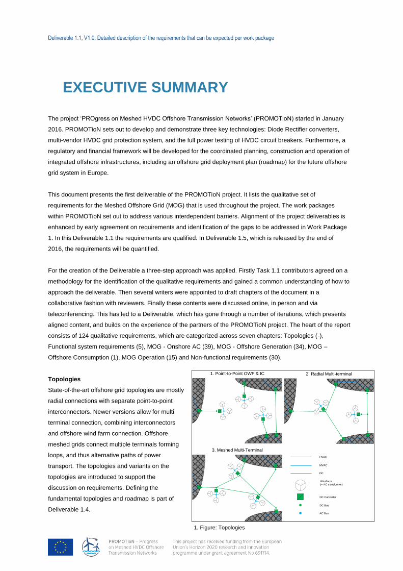
Topologies
State-of-the-art offshore grid topologies are mostly
radial connections with separate point-to-point
interconnectors. Newer versions allow for multi
terminal connection, combining interconnectors
and offshore wind farm connection. Offshore
meshed grids connect multiple terminals forming
loops, and thus alternative paths of power
transport. The topologies and variants on the
topologies are introduced to support the
discussion on requirements. Defining the
fundamental topologies and roadmap is part of
Deliverable 1.4.
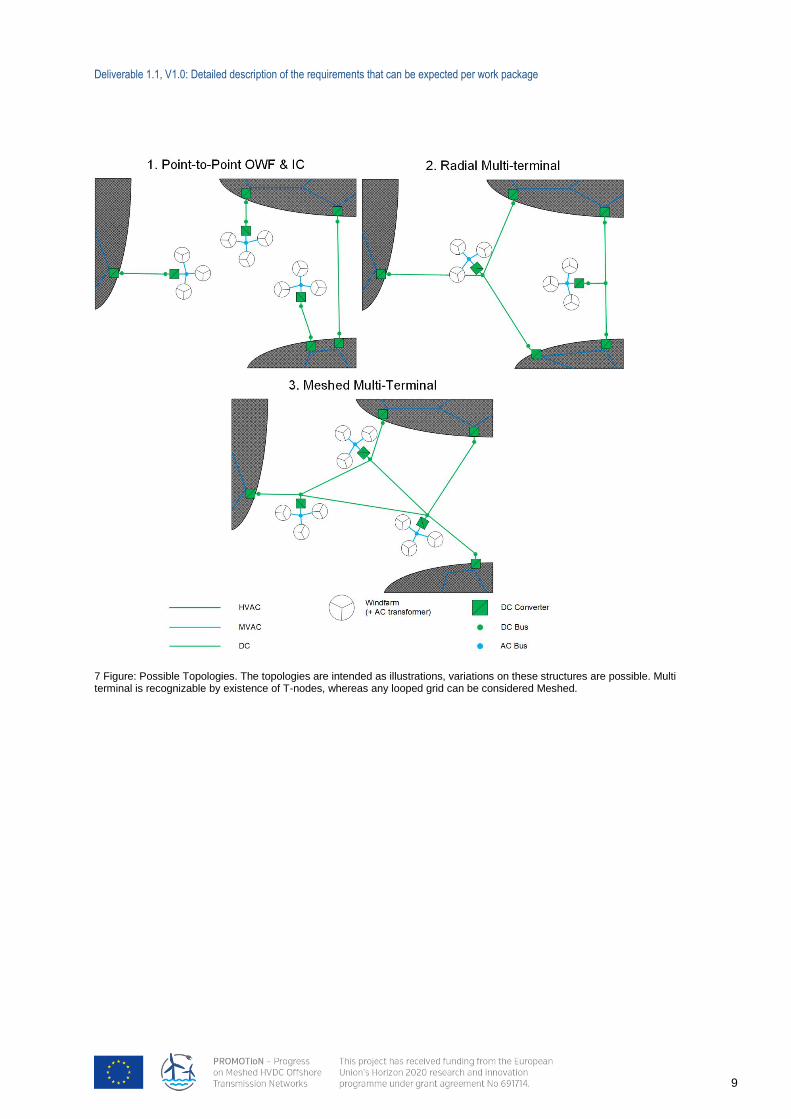
DC Converter
Windfarm
(+ AC transformer)
HVAC
MVAC
DC
1. Point-to-Point OWF & IC
3. Meshed Multi-Terminal
DC Bus
AC Bus
2. Radial Multi-terminal
1. Figure: Topologies
Deliverable 1.1, V1.0: Detailed description of the requirements that can be expected per work package
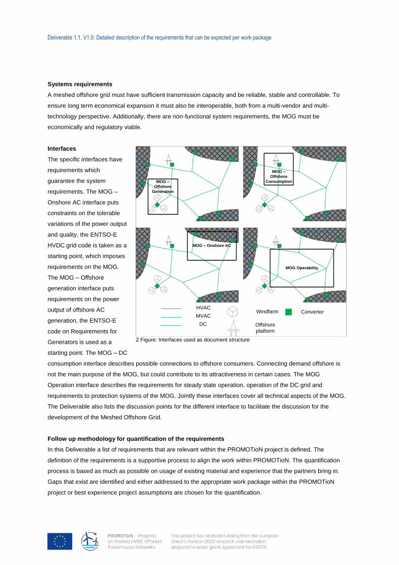
Systems requirements
A meshed offshore grid must have sufficient transmission capacity and be reliable, stable and controllable. To
ensure long term economical expansion it must also be interoperable, both from a multi-vendor and multi-
technology perspective. Additionally, there are non-functional system requirements, the MOG must be
economically and regulatory viable.
Interfaces
The specific interfaces have
requirements which
guarantee the system
requirements. The MOG –
Onshore AC interface puts
constraints on the tolerable
variations of the power output
and quality, the ENTSO-E
HVDC grid code is taken as a
starting point, which imposes
requirements on the MOG.
The MOG – Offshore
generation interface puts
requirements on the power
output of offshore AC
generation, the ENTSO-E
code on Requirements for
Generators is used as a
starting point. The MOG – DC
consumption interface describes possible connections to offshore consumers. Connecting demand offshore is
not the main purpose of the MOG, but could contribute to its attractiveness in certain cases. The MOG
Operation interface describes the requirements for steady state operation, operation of the DC grid and
requirements to protection systems of the MOG. Jointly these interfaces cover all technical aspects of the MOG.
The Deliverable also lists the discussion points for the different interface to facilitate the discussion for the
development of the Meshed Offshore Grid.
Follow up methodology for quantification of the requirements
In this Deliverable a list of requirements that are relevant within the PROMOTioN project is defined. The
definition of the requirements is a supportive process to align the work within PROMOTioN. The quantification
process is based as much as possible on usage of existing material and experience that the partners bring in.
Gaps that exist are identified and either addressed to the appropriate work package within the PROMOTioN
project or best experience project assumptions are chosen for the quantification.
MOG –
Offshore
Generation
MOG –
Offshore
Consumption
MOG – Onshore AC
MOG Operability
ConverterWindfarmHVAC
MVAC
DC Offshore
platform
2 Figure: Interfaces used as document structure
Deliverable 1.1, V1.0: Detailed description of the requirements that can be expected per work package
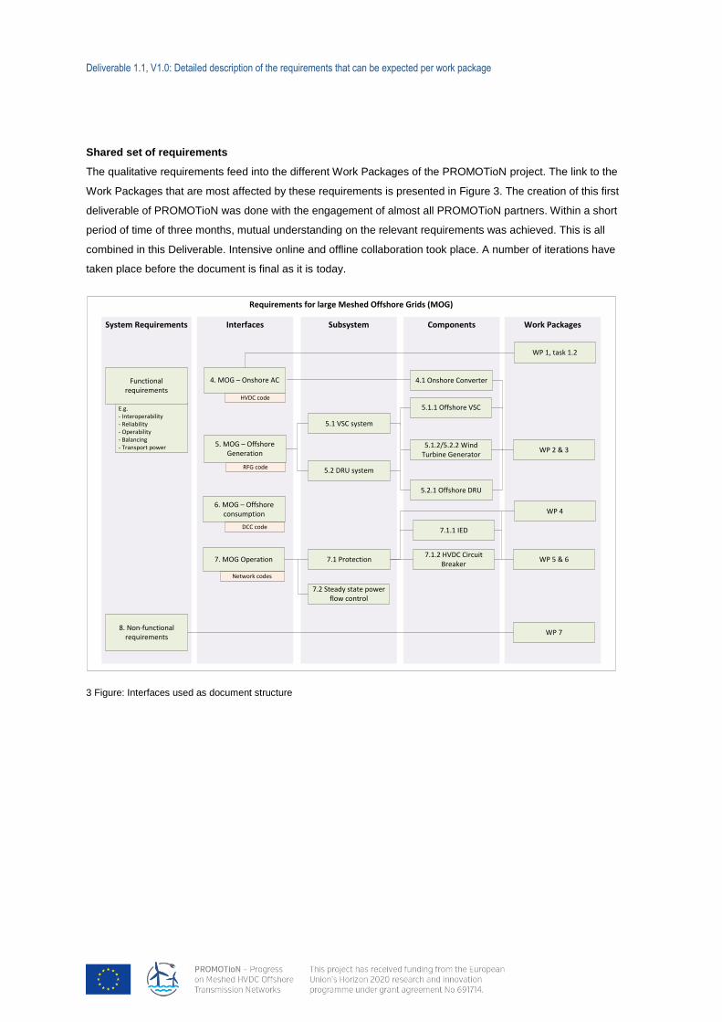
Shared set of requirements
The qualitative requirements feed into the different Work Packages of the PROMOTioN project. The link to the
Work Packages that are most affected by these requirements is presented in Figure 3. The creation of this first
deliverable of PROMOTioN was done with the engagement of almost all PROMOTioN partners. Within a short
period of time of three months, mutual understanding on the relevant requirements was achieved. This is all
combined in this Deliverable. Intensive online and offline collaboration took place. A number of iterations have
taken place before the document is final as it is today.
3 Figure: Interfaces used as document structure
Requirements for large Meshed Offshore Grids (MOG)
Work PackagesComponentsInterfacesSystem Requirements
8. Non-functional requirements
5. MOG – Offshore Generation
6. MOG – Offshore consumption
4. MOG – Onshore AC
7. MOG Operation7.1.2 HVDC Circuit
Breaker
5.2.1 Offshore DRU
5.1.1 Offshore VSC
5.1.2/5.2.2 Wind Turbine Generator
WP 5 & 6
WP 1, task 1.2
WP 2 & 3
RFG code
DCC code
HVDC code
Network codes
E.g. - Interoperability- Reliability- Operability- Balancing- Transport power
Subsystem
7.1 Protection
5.2 DRU system
5.1 VSC system
WP 4
7.1.1 IED
WP 7
Functional requirements
4.1 Onshore Converter
7.2 Steady state power flow control
Deliverable 1.1, V1.0: Detailed description of the requirements that can be expected per work package
CONTENT
Document info sheet .............................................................................................................................................................. i
List of Contributors ............................................................................................................................................................... ii
Executive summary .............................................................................................................................................................. iii
Content .................................................................................................................................................................................. vi
1 Terminology ................................................................................................................................................................... 1
1.1 List of Abbreviations ................................................................................................................................................ 1
1.2 List of Components .................................................................................................................................................. 2
2 Introduction.................................................................................................................................................................... 4
2.1 Methodology for qualifying the requirements ........................................................................................................... 5
2.2 Structure of the document ....................................................................................................................................... 6
2.3 Topologies ............................................................................................................................................................... 8
3 Functional system requirements ............................................................................................................................... 21
3.1 System requirements ............................................................................................................................................. 21
3.2 Discussion of system requirements ....................................................................................................................... 26
4 Meshed Offshore Grid – Onshore AC ........................................................................................................................ 27
4.1 HVDC Grid code .................................................................................................................................................... 27
4.2 General requirements for HVDC systems (Onshore HVDC converter stations).................................................... 28
4.3 Discussion on HVDC code .................................................................................................................................... 36
5 Requirements for offshore generation ...................................................................................................................... 38
5.1 Requirements for Offshore Wind Farms (OWFs) .................................................................................................. 39
5.2 Requirements for offshore HVDC Terminals ......................................................................................................... 42
5.3 Discussion of the Offshore Generation requirements ............................................................................................ 44
6 Meshed Offshore Grid- Offshore Consumption ....................................................................................................... 45
6.1 Offshore electrical consumption of Oil & Gas exploration ..................................................................................... 45
6.2 Future offshore power consumption ...................................................................................................................... 46
6.3 Requirements for the connection of consumption to the MOG .............................................................................. 47
7 Meshed Offshore Grid – Operation ............................................................................................................................ 48
7.1 Requirements for HVDC Terminals ....................................................................................................................... 48
7.2 DC grid protection and control requirements ......................................................................................................... 51
7.3 Steady state operation ........................................................................................................................................... 55
7.4 Discussion of requirements ................................................................................................................................... 56
Deliverable 1.1, V1.0: Detailed description of the requirements that can be expected per work package
8 Non-functional requirements ..................................................................................................................................... 57
8.1 Energy policy aspects ............................................................................................................................................ 57
8.2 Legal and regulatory aspects ................................................................................................................................ 57
8.3 Financial-economic aspects .................................................................................................................................. 59
8.4 Market aspects ...................................................................................................................................................... 59
ANNEX 1 Detailed description of protection system requirements ............................................................................... 60
ANNEX 2 Connection chapters to WPs ............................................................................................................................. 71
ANNEX 3 HVDC grid code .................................................................................................................................................. 72
ANNEX 4 DRU specific topologies .................................................................................................................................... 94
Deliverable 1.1, V1.0: Detailed description of the requirements that can be expected per work package
1
1 TERMINOLOGY
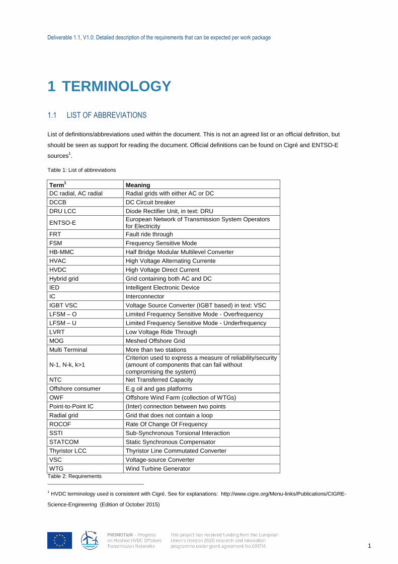
1.1 LIST OF ABBREVIATIONS
List of definitions/abbreviations used within the document. This is not an agreed list or an official definition, but
should be seen as support for reading the document. Official definitions can be found on Cigré and ENTSO-E
sources1.
Table 1: List of abbreviations
Term1 Meaning
DC radial, AC radial Radial grids with either AC or DC
DCCB DC Circuit breaker
DRU LCC Diode Rectifier Unit, in text: DRU
ENTSO-E European Network of Transmission System Operators for Electricity
FRT Fault ride through
FSM Frequency Sensitive Mode
HB-MMC Half Bridge Modular Multilevel Converter
HVAC High Voltage Alternating Currente
HVDC High Voltage Direct Current
Hybrid grid Grid containing both AC and DC
IED Intelligent Electronic Device
IC Interconnector
IGBT VSC Voltage Source Converter (IGBT based) in text: VSC
LFSM – O Limited Frequency Sensitive Mode - Overfrequency
LFSM – U Limited Frequency Sensitive Mode - Underfrequency
LVRT Low Voltage Ride Through
MOG Meshed Offshore Grid
Multi Terminal More than two stations
N-1, N-k, k>1 Criterion used to express a measure of reliability/security (amount of components that can fail without compromising the system)
NTC Net Transferred Capacity
Offshore consumer E.g oil and gas platforms
OWF Offshore Wind Farm (collection of WTGs)
Point-to-Point IC (Inter) connection between two points
Radial grid Grid that does not contain a loop
ROCOF Rate Of Change Of Frequency
SSTI Sub-Synchronous Torsional Interaction
STATCOM Static Synchronous Compensator
Thyristor LCC Thyristor Line Commutated Converter
VSC Voltage-source Converter
WTG Wind Turbine Generator
Table 2: Requirements
1 HVDC terminology used is consistent with Cigré. See for explanations: http://www.cigre.org/Menu-links/Publications/CIGRE-
Science-Engineering (Edition of October 2015)
Deliverable 1.1, V1.0: Detailed description of the requirements that can be expected per work package
2
Requirements
System Higher level requirement to the whole Meshed Offshore Grid
Functional Higher level technical requirement
Non-Functional Higher level non-technical requirement
Project Requirements to the project (e.g. cooperation, communication within PROMOTioN)
Sub-system Part of a system (e.g Protection system, as part of a grid)
Component Makes up the sub-system (e.g. HVDC cable, HVDC CBs, IED)
Detailed requirement Defines a requirement of a component (e.g. maximum opening time of a HVDC CB)
1.2 LIST OF COMPONENTS
The list of components serves to delineate what is meant as a component within this deliverable. The
components are defined at a sufficiently high level as to allow discussion about the development of the Meshed
Offshore Grid. Furthermore this paragraph provides a definition of protection subsystems.
Component - constituent part of a device which cannot be physically divided into smaller parts without losing its
particular function2
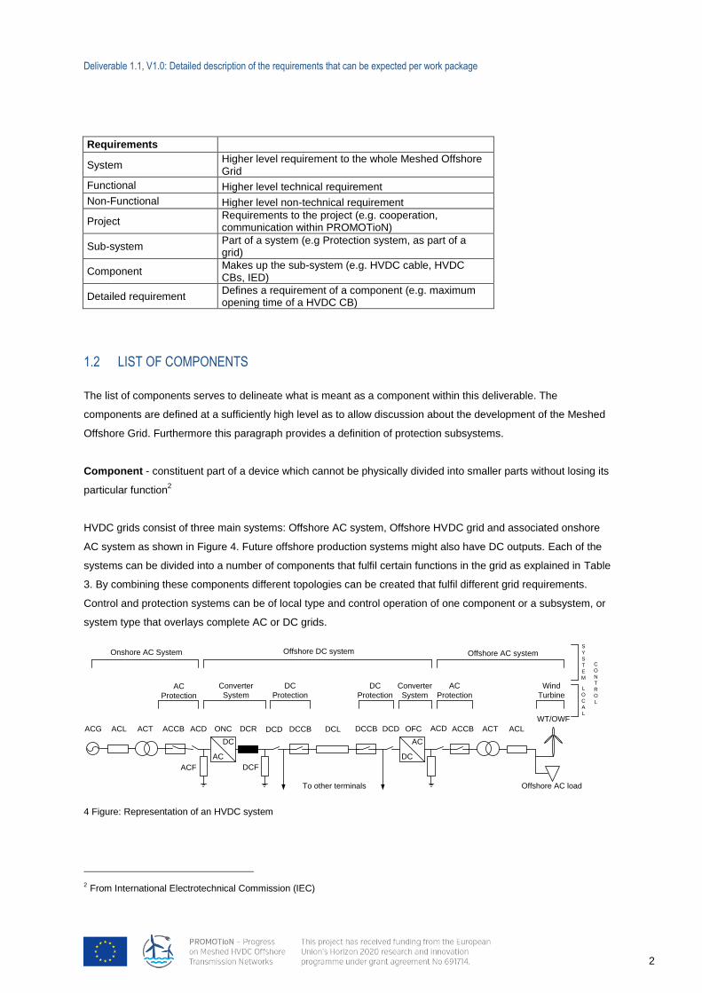
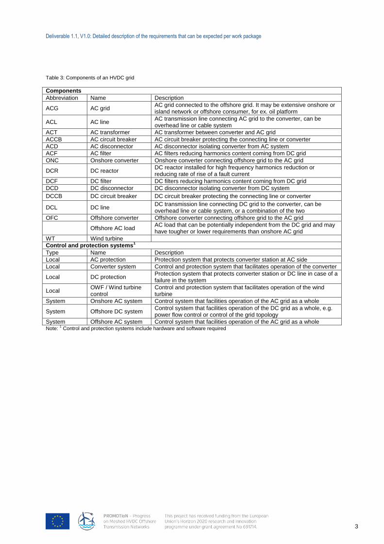
HVDC grids consist of three main systems: Offshore AC system, Offshore HVDC grid and associated onshore
AC system as shown in Figure 4. Future offshore production systems might also have DC outputs. Each of the
systems can be divided into a number of components that fulfil certain functions in the grid as explained in Table
3. By combining these components different topologies can be created that fulfil different grid requirements.
Control and protection systems can be of local type and control operation of one component or a subsystem, or
system type that overlays complete AC or DC grids.
4 Figure: Representation of an HVDC system
2 From International Electrotechnical Commission (IEC)
AC
DC
DC
AC
To other terminals
ACG
Offshore AC load
ACL ACT ACCB ACD
ACF
ONC DCR
DCF
DCCB DCLDCD DCCB DCD OFC ACLACTACCBACD
WT/OWF
Onshore AC System
AC
Protection
DC
Protection
Converter
System
DC
Protection
Converter
System
AC
Protection
Wind
Turbine
Offshore AC systemOffshore DC system
L
O
C
A
L
S
Y
S
T
E
M
C
O
N
T
R
O
L
Deliverable 1.1, V1.0: Detailed description of the requirements that can be expected per work package
3
Table 3: Components of an HVDC grid
Components
Abbreviation Name Description
ACG AC grid AC grid connected to the offshore grid. It may be extensive onshore or island network or offshore consumer, for ex. oil platform
ACL AC line AC transmission line connecting AC grid to the converter, can be overhead line or cable system
ACT AC transformer AC transformer between converter and AC grid
ACCB AC circuit breaker AC circuit breaker protecting the connecting line or converter
ACD AC disconnector AC disconnector isolating converter from AC system
ACF AC filter AC filters reducing harmonics content coming from DC grid
ONC Onshore converter Onshore converter connecting offshore grid to the AC grid
DCR DC reactor DC reactor installed for high frequency harmonics reduction or reducing rate of rise of a fault current
DCF DC filter DC filters reducing harmonics content coming from DC grid
DCD DC disconnector DC disconnector isolating converter from DC system
DCCB DC circuit breaker DC circuit breaker protecting the connecting line or converter
DCL DC line DC transmission line connecting DC grid to the converter, can be overhead line or cable system, or a combination of the two
OFC Offshore converter Offshore converter connecting offshore grid to the AC grid
Offshore AC load AC load that can be potentially independent from the DC grid and may have tougher or lower requirements than onshore AC grid
WT Wind turbine
Control and protection systems1
Type Name Description
Local AC protection Protection system that protects converter station at AC side
Local Converter system Control and protection system that facilitates operation of the converter
Local DC protection Protection system that protects converter station or DC line in case of a failure in the system
Local OWF / Wind turbine control
Control and protection system that facilitates operation of the wind turbine
System Onshore AC system Control system that facilities operation of the AC grid as a whole
System Offshore DC system Control system that facilities operation of the DC grid as a whole, e.g. power flow control or control of the grid topology
System Offshore AC system Control system that facilities operation of the AC grid as a whole Note:
1 Control and protection systems include hardware and software required
Deliverable 1.1, V1.0: Detailed description of the requirements that can be expected per work package
4
2 INTRODUCTION
PROMOTioN aims to overcome technological, financial and regulatory barriers towards a Meshed HVDC
Offshore Grid (MOG). It will do so by development and demonstration of three key technologies (Diode Rectifier
Units (DRUs), HVDC Circuit Breakers and HVDC grid protection systems, a regulatory and financial framework
and an offshore grid deployment plan for 2020 and beyond. Work Package 1 (WP1) will define the requirements
for the Meshed Offshore Grid. This WP is divided into five Tasks:
Define requirements, reference scenarios and fundamental topologies
Studies, available and emerging technologies for offshore grids
Assessment and inputs from existing offshore connections and grids
Initial roadmap for the evacuation of offshore renewable generation
Re-evaluate requirements based on work of other packages
Deliverable 1.1 (D1.1) is the first Deliverable of the PROMOTioN project and it is also Task 1.1 of WP1. The
Deliverable provides a detailed description of the requirements to be applied to each following WP. This will
ensure that all WPs work within the same vision, based upon a set of coherent and consistent requirements.
Acceptance of Deliverable 1.1 leads to the accomplishment of Milestone 1 (MS1), which is achieved after
alignment and agreement of the consortium about D1.1 and the requirements it contains. D1.1 will facilitate the
compatibility and consistency of the deliverables of individual WPs towards the overall objectives of the project.
The set of requirements will be inventoried and listed in this report. The quantification of these requirements is
part of Task 1.2 and 1.3. The reference scenario and fundamental topologies will be part of later Deliverables. In
this document they are introduced, when necessary for the requirements. The requirements are a combined
effort of all relevant parties within the consortium and should form a complete picture of what is required of a
Meshed Offshore Grid (MOG) by any of the partners.
This chapter introduces the following topics:
The methodology for qualifying the requirements
Structure of the document
Topologies
Deliverable 1.1, V1.0: Detailed description of the requirements that can be expected per work package
5
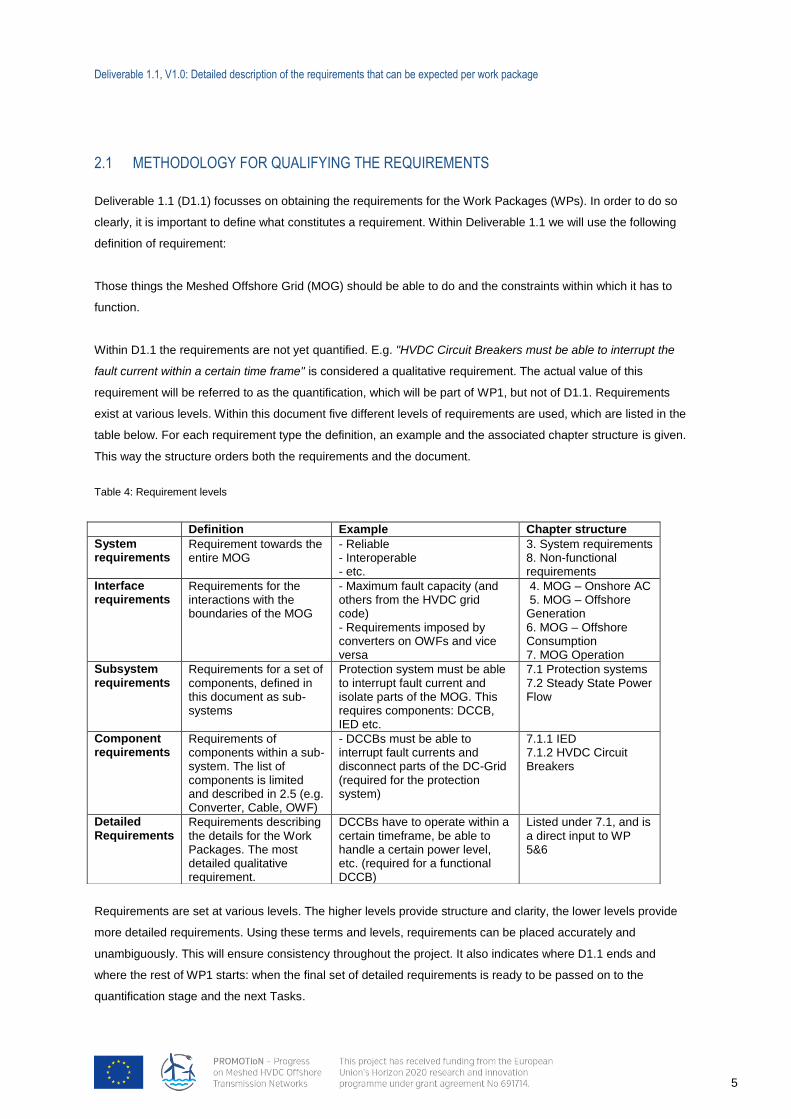
2.1 METHODOLOGY FOR QUALIFYING THE REQUIREMENTS
Deliverable 1.1 (D1.1) focusses on obtaining the requirements for the Work Packages (WPs). In order to do so
clearly, it is important to define what constitutes a requirement. Within Deliverable 1.1 we will use the following
definition of requirement:
Those things the Meshed Offshore Grid (MOG) should be able to do and the constraints within which it has to
function.
Within D1.1 the requirements are not yet quantified. E.g. "HVDC Circuit Breakers must be able to interrupt the
fault current within a certain time frame" is considered a qualitative requirement. The actual value of this
requirement will be referred to as the quantification, which will be part of WP1, but not of D1.1. Requirements
exist at various levels. Within this document five different levels of requirements are used, which are listed in the
table below. For each requirement type the definition, an example and the associated chapter structure is given.
This way the structure orders both the requirements and the document.
Table 4: Requirement levels
Requirements are set at various levels. The higher levels provide structure and clarity, the lower levels provide
more detailed requirements. Using these terms and levels, requirements can be placed accurately and
unambiguously. This will ensure consistency throughout the project. It also indicates where D1.1 ends and
where the rest of WP1 starts: when the final set of detailed requirements is ready to be passed on to the
quantification stage and the next Tasks.
Definition Example Chapter structure
System requirements
Requirement towards the entire MOG
- Reliable - Interoperable - etc.
3. System requirements 8. Non-functional requirements
Interface requirements
Requirements for the interactions with the boundaries of the MOG
- Maximum fault capacity (and others from the HVDC grid code) - Requirements imposed by converters on OWFs and vice versa
4. MOG – Onshore AC 5. MOG – Offshore Generation 6. MOG – Offshore Consumption 7. MOG Operation
Subsystem requirements
Requirements for a set of components, defined in this document as sub-systems
Protection system must be able to interrupt fault current and isolate parts of the MOG. This requires components: DCCB, IED etc.
7.1 Protection systems 7.2 Steady State Power Flow
Component requirements
Requirements of components within a sub-system. The list of components is limited and described in 2.5 (e.g. Converter, Cable, OWF)
- DCCBs must be able to interrupt fault currents and disconnect parts of the DC-Grid (required for the protection system)
7.1.1 IED 7.1.2 HVDC Circuit Breakers
Detailed Requirements
Requirements describing the details for the Work Packages. The most detailed qualitative requirement.
DCCBs have to operate within a certain timeframe, be able to handle a certain power level, etc. (required for a functional DCCB)
Listed under 7.1, and is a direct input to WP 5&6
Deliverable 1.1, V1.0: Detailed description of the requirements that can be expected per work package
6
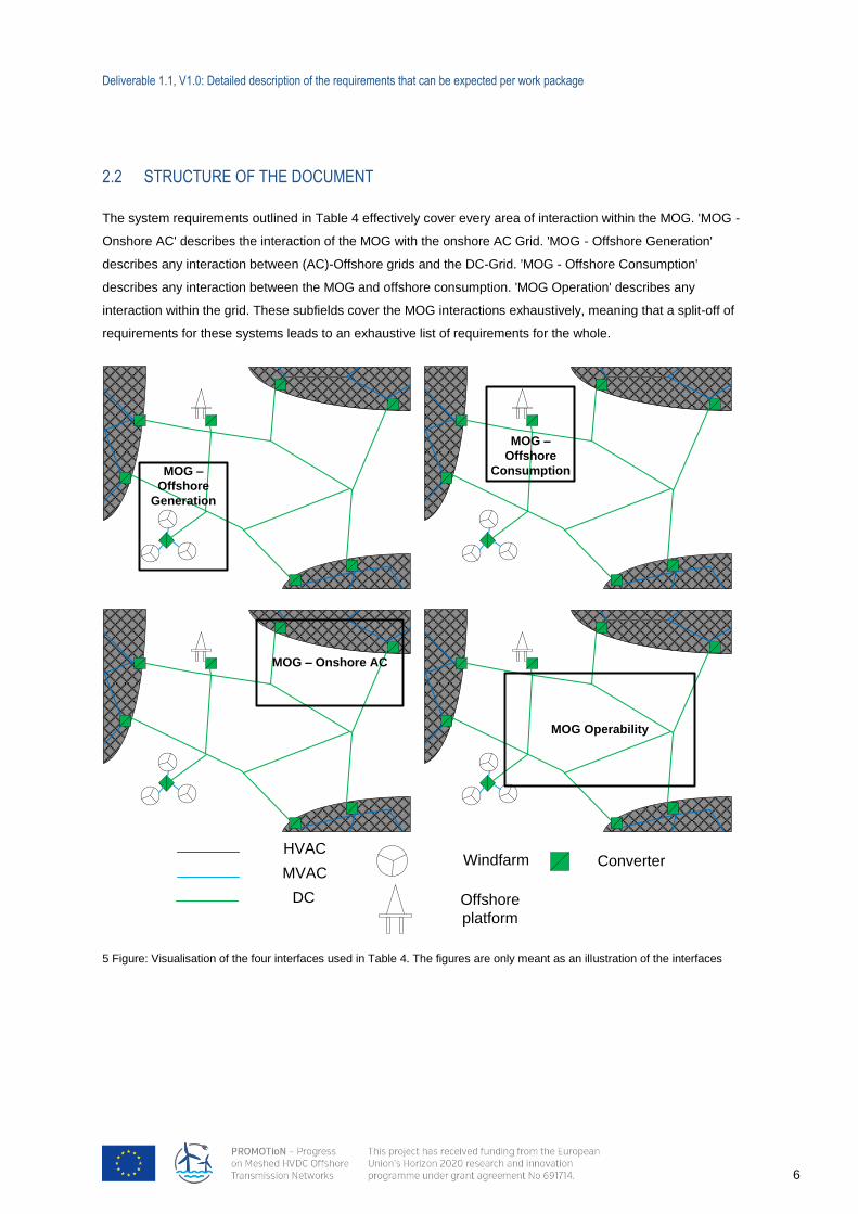
2.2 STRUCTURE OF THE DOCUMENT
The system requirements outlined in Table 4 effectively cover every area of interaction within the MOG. 'MOG -
Onshore AC' describes the interaction of the MOG with the onshore AC Grid. 'MOG - Offshore Generation'
describes any interaction between (AC)-Offshore grids and the DC-Grid. 'MOG - Offshore Consumption'
describes any interaction between the MOG and offshore consumption. 'MOG Operation' describes any
interaction within the grid. These subfields cover the MOG interactions exhaustively, meaning that a split-off of
requirements for these systems leads to an exhaustive list of requirements for the whole.
5 Figure: Visualisation of the four interfaces used in Table 4. The figures are only meant as an illustration of the interfaces
MOG –
Offshore
Generation
MOG –
Offshore
Consumption
MOG – Onshore AC
MOG Operability
ConverterWindfarmHVAC
MVAC
DC Offshore
platform
Deliverable 1.1, V1.0: Detailed description of the requirements that can be expected per work package
7
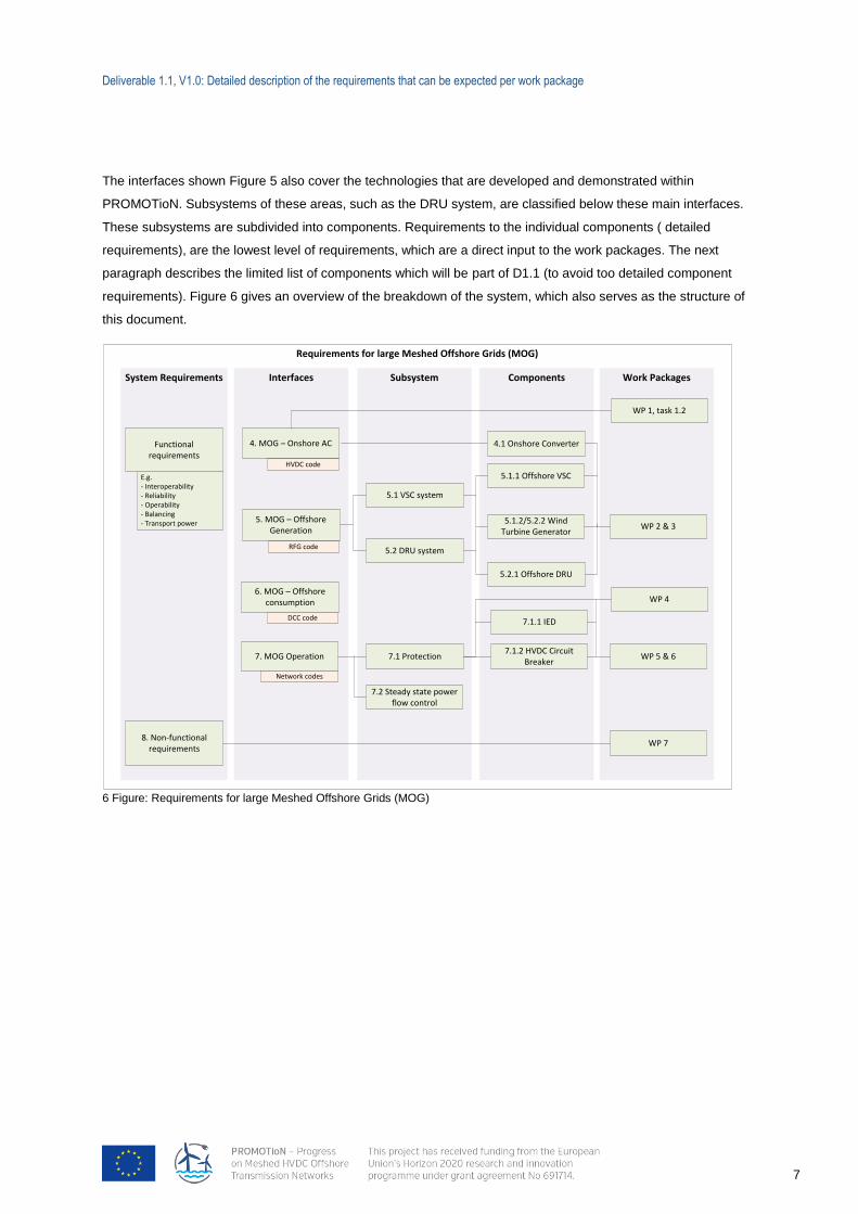
The interfaces shown Figure 5 also cover the technologies that are developed and demonstrated within
PROMOTioN. Subsystems of these areas, such as the DRU system, are classified below these main interfaces.
These subsystems are subdivided into components. Requirements to the individual components ( detailed
requirements), are the lowest level of requirements, which are a direct input to the work packages. The next
paragraph describes the limited list of components which will be part of D1.1 (to avoid too detailed component
requirements). Figure 6 gives an overview of the breakdown of the system, which also serves as the structure of
this document.
6 Figure: Requirements for large Meshed Offshore Grids (MOG)
Requirements for large Meshed Offshore Grids (MOG)
Work PackagesComponentsInterfacesSystem Requirements
8. Non-functional requirements
5. MOG – Offshore Generation
6. MOG – Offshore consumption
4. MOG – Onshore AC
7. MOG Operation7.1.2 HVDC Circuit
Breaker
5.2.1 Offshore DRU
5.1.1 Offshore VSC
5.1.2/5.2.2 Wind Turbine Generator
WP 5 & 6
WP 1, task 1.2
WP 2 & 3
RFG code
DCC code
HVDC code
Network codes
E.g. - Interoperability- Reliability- Operability- Balancing- Transport power
Subsystem
7.1 Protection
5.2 DRU system
5.1 VSC system
WP 4
7.1.1 IED
WP 7
Functional requirements
4.1 Onshore Converter
7.2 Steady state power flow control
Deliverable 1.1, V1.0: Detailed description of the requirements that can be expected per work package
8
2.3 TOPOLOGIES
Topologies are introduced in this document to support discussion about the requirements. These are not the
final topologies that will be the input to the work packages for simulation modelling and system studies. The
fundamental topologies will be further defined and agreed upon in Deliverable 1.4. The aim is to define a
number of potential offshore network configurations that can be used to test and demonstrate operation,
protection and control and provide a basis for cost-benefit comparison. Particular topics to be addressed in the
technical assessment include:
Control of voltage at each terminal during normal operation.
Control of current on each branch during normal operation.
Detection and clearance of short-circuit faults.
Interactions between network controls and wind farm controls during normal operation.
Transient interactions between network controls and wind farm controls.
Interactions with onshore AC systems, e.g. in respect of loss of infeed, regulation of voltage, regulation
of frequency and potential contributions to AC system stability.
Start-up and shut-down of the offshore grid or parts of it.
Possibility of re-routing of power in case of reconfiguration of the grid due to failures.
Three main topology types have been identified with reference to existing literature and previous offshore grid
studies. These are defined in Figure 6. and discussed along with a number of possible variants on each. The
nature and significance of the key variants are then discussed in more detail in the section below.
Deliverable 1.1, V1.0: Detailed description of the requirements that can be expected per work package
9
7 Figure: Possible Topologies. The topologies are intended as illustrations, variations on these structures are possible. Multi terminal is recognizable by existence of T-nodes, whereas any looped grid can be considered Meshed.
Deliverable 1.1, V1.0: Detailed description of the requirements that can be expected per work package
10
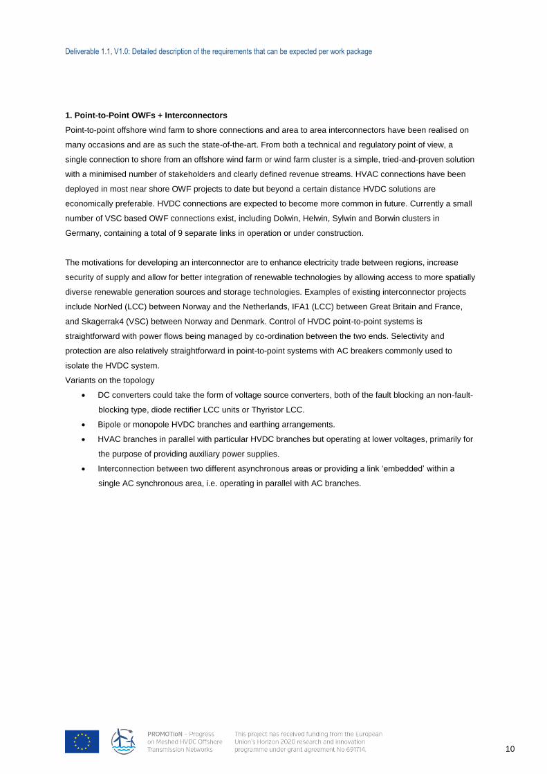
1. Point-to-Point OWFs + Interconnectors
Point-to-point offshore wind farm to shore connections and area to area interconnectors have been realised on
many occasions and are as such the state-of-the-art. From both a technical and regulatory point of view, a
single connection to shore from an offshore wind farm or wind farm cluster is a simple, tried-and-proven solution
with a minimised number of stakeholders and clearly defined revenue streams. HVAC connections have been
deployed in most near shore OWF projects to date but beyond a certain distance HVDC solutions are
economically preferable. HVDC connections are expected to become more common in future. Currently a small
number of VSC based OWF connections exist, including Dolwin, Helwin, Sylwin and Borwin clusters in
Germany, containing a total of 9 separate links in operation or under construction.
The motivations for developing an interconnector are to enhance electricity trade between regions, increase
security of supply and allow for better integration of renewable technologies by allowing access to more spatially
diverse renewable generation sources and storage technologies. Examples of existing interconnector projects
include NorNed (LCC) between Norway and the Netherlands, IFA1 (LCC) between Great Britain and France,
and Skagerrak4 (VSC) between Norway and Denmark. Control of HVDC point-to-point systems is
straightforward with power flows being managed by co-ordination between the two ends. Selectivity and
protection are also relatively straightforward in point-to-point systems with AC breakers commonly used to
isolate the HVDC system.
Variants on the topology
DC converters could take the form of voltage source converters, both of the fault blocking an non-fault-
blocking type, diode rectifier LCC units or Thyristor LCC.
Bipole or monopole HVDC branches and earthing arrangements.
HVAC branches in parallel with particular HVDC branches but operating at lower voltages, primarily for
the purpose of providing auxiliary power supplies.
Interconnection between two different asynchronous areas or providing a link ‘embedded’ within a
single AC synchronous area, i.e. operating in parallel with AC branches.
Deliverable 1.1, V1.0: Detailed description of the requirements that can be expected per work package
11
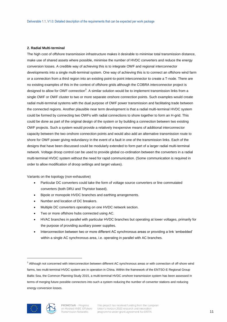
2. Radial Multi-terminal
The high cost of offshore transmission infrastructure makes it desirable to minimise total transmission distance,
make use of shared assets where possible, minimise the number of HVDC converters and reduce the energy
conversion losses. A credible way of achieving this is to integrate OWF and regional interconnector
developments into a single multi-terminal system. One way of achieving this is to connect an offshore wind farm
or a connection from a third region into an existing point-to-point interconnector to create a T-node. There are
no existing examples of this in the context of offshore grids although the COBRA interconnector project is
designed to allow for OWF connection3. A similar solution would be to implement transmission links from a
single OWF or OWF cluster to two or more separate onshore connection points. Such examples would create
radial multi-terminal systems with the dual purpose of OWF power transmission and facilitating trade between
the connected regions. Another plausible near term development is that a radial multi-terminal HVDC system
could be formed by connecting two OWFs with radial connections to shore together to form an H-grid. This
could be done as part of the original design of the system or by building a connection between two existing
OWF projects. Such a system would provide a relatively inexpensive means of additional interconnector
capacity between the two onshore connection points and would also add an alternative transmission route to
shore for OWF power giving redundancy in the event of a fault in one of the transmission links. Each of the
designs that have been discussed could be modularly extended to form part of a larger radial multi-terminal
network. Voltage droop control can be used to provide global co-ordination between the converters in a radial
multi-terminal HVDC system without the need for rapid communication. (Some communication is required in
order to allow modification of droop settings and target values).
Variants on the topology (non-exhaustive)
Particular DC converters could take the form of voltage source converters or line commutated
converters (both DRU and Thyristor based).
Bipole or monopole HVDC branches and earthing arrangements.
Number and location of DC breakers.
Multiple DC converters operating on one HVDC network section.
Two or more offshore hubs connected using AC.
HVAC branches in parallel with particular HVDC branches but operating at lower voltages, primarily for
the purpose of providing auxiliary power supplies.
Interconnection between two or more different AC synchronous areas or providing a link ‘embedded’
within a single AC synchronous area, i.e. operating in parallel with AC branches.
3 Although not concerned with interconnection between different AC synchronous areas or with connection of off-shore wind
farms, two multi-terminal HVDC system are in operation in China. Within the framework of the ENTSO-E Regional Group
Baltic Sea, the Common Planning Study 2015, a multi-terminal HVDC onshore transmission system has been assessed in
terms of merging future possible connectors into such a system reducing the number of converter stations and reducing
energy conversion losses.
Deliverable 1.1, V1.0: Detailed description of the requirements that can be expected per work package
12
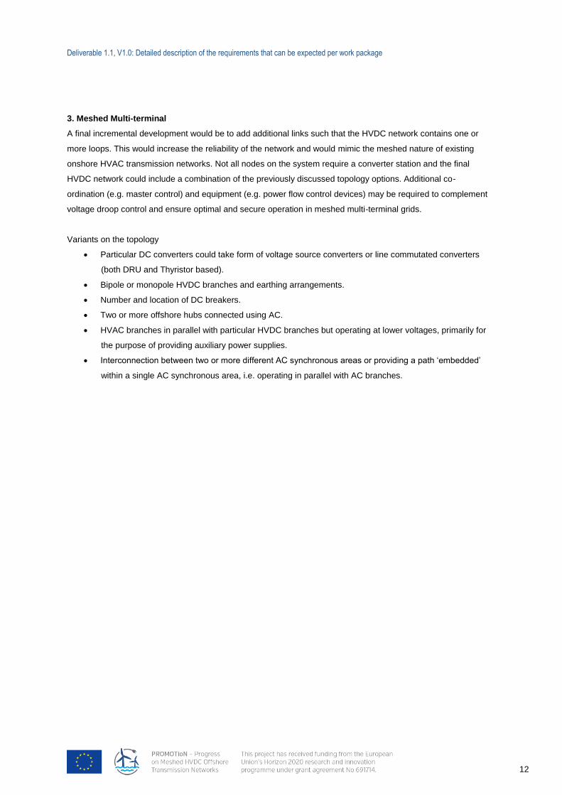
3. Meshed Multi-terminal
A final incremental development would be to add additional links such that the HVDC network contains one or
more loops. This would increase the reliability of the network and would mimic the meshed nature of existing
onshore HVAC transmission networks. Not all nodes on the system require a converter station and the final
HVDC network could include a combination of the previously discussed topology options. Additional co-
ordination (e.g. master control) and equipment (e.g. power flow control devices) may be required to complement
voltage droop control and ensure optimal and secure operation in meshed multi-terminal grids.
Variants on the topology
Particular DC converters could take form of voltage source converters or line commutated converters
(both DRU and Thyristor based).
Bipole or monopole HVDC branches and earthing arrangements.
Number and location of DC breakers.
Two or more offshore hubs connected using AC.
HVAC branches in parallel with particular HVDC branches but operating at lower voltages, primarily for
the purpose of providing auxiliary power supplies.
Interconnection between two or more different AC synchronous areas or providing a path ‘embedded’
within a single AC synchronous area, i.e. operating in parallel with AC branches.
Deliverable 1.1, V1.0: Detailed description of the requirements that can be expected per work package
13
2.3.1 DISCUSSION OF TOPOLOGY VARIANTS
The fundamental topologies that have been discussed are seen as credible options towards the development of
a fully meshed offshore HVDC network. In each case it is possible that varying technology, configuration,
protection and control options could be implemented within the delivery of the final solution. Some of those
options are discussed in more detail in the following sections.
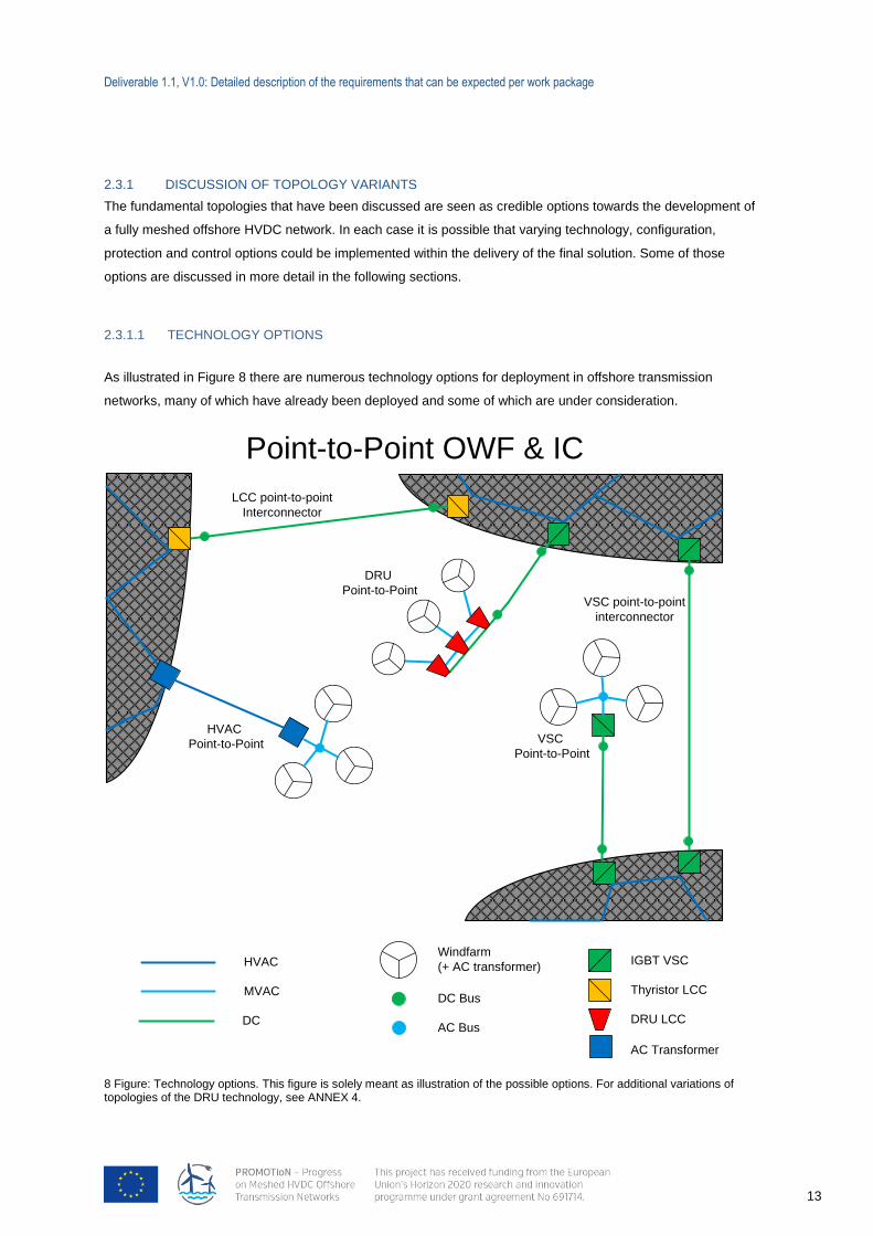
2.3.1.1 TECHNOLOGY OPTIONS
As illustrated in Figure 8 there are numerous technology options for deployment in offshore transmission
networks, many of which have already been deployed and some of which are under consideration.
8 Figure: Technology options. This figure is solely meant as illustration of the possible options. For additional variations of topologies of the DRU technology, see ANNEX 4.
IGBT VSC
Thyristor LCC
DRU LCC
Windfarm
(+ AC transformer)HVAC
MVAC
DC
LCC point-to-point
Interconnector
VSC point-to-point
interconnector
AC Transformer
Point-to-Point OWF & IC
HVAC
Point-to-Point
DRU
Point-to-Point
VSC
Point-to-Point
DC Bus
AC Bus
Deliverable 1.1, V1.0: Detailed description of the requirements that can be expected per work package
14
The PROMOTioN project will investigate the degree to which some of these technology options can be
deployed within the generic offshore network topology structures outlined in Figure 8 and demonstrate the
protection and control systems required to facilitate this. The main focus will be on the deployment of VSC
converter and DRU technology within HVDC network topologies. However, it is also feasible that AC technology
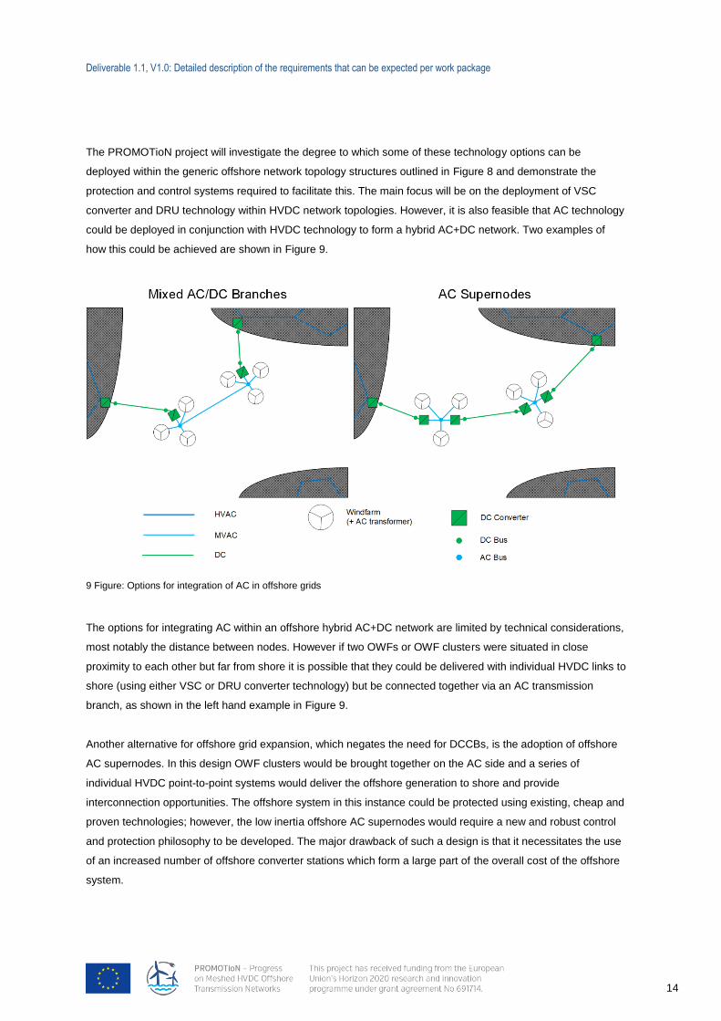
could be deployed in conjunction with HVDC technology to form a hybrid AC+DC network. Two examples of
how this could be achieved are shown in Figure 9.
9 Figure: Options for integration of AC in offshore grids
The options for integrating AC within an offshore hybrid AC+DC network are limited by technical considerations,
most notably the distance between nodes. However if two OWFs or OWF clusters were situated in close
proximity to each other but far from shore it is possible that they could be delivered with individual HVDC links to
shore (using either VSC or DRU converter technology) but be connected together via an AC transmission
branch, as shown in the left hand example in Figure 9.
Another alternative for offshore grid expansion, which negates the need for DCCBs, is the adoption of offshore
AC supernodes. In this design OWF clusters would be brought together on the AC side and a series of
individual HVDC point-to-point systems would deliver the offshore generation to shore and provide
interconnection opportunities. The offshore system in this instance could be protected using existing, cheap and
proven technologies; however, the low inertia offshore AC supernodes would require a new and robust control
and protection philosophy to be developed. The major drawback of such a design is that it necessitates the use
of an increased number of offshore converter stations which form a large part of the overall cost of the offshore
system.

Deliverable 1.1, V1.0: Detailed description of the requirements that can be expected per work package
15
The inception of DC network building on existing point to point schemes and possible meshed offshore networks
may require additional DC equipment such as dynamic breaking systems (DC chopper) DC-DC converters,
especially between differing voltage schemes, and current flow controllers. This equipment will enable greater
optimisation of DC systems and are available today, albeit the cost benefit unclear. Thus, converter topologies,
network configurations and control and protection schemes studied in PROMOTioN should consider this
additional equipment and how it complements the proposed solutions in PROMOTioN.
Deliverable 1.1, V1.0: Detailed description of the requirements that can be expected per work package
16
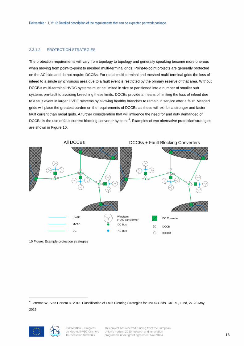
2.3.1.2 PROTECTION STRATEGIES
The protection requirements will vary from topology to topology and generally speaking become more onerous
when moving from point-to-point to meshed multi-terminal grids. Point-to-point projects are generally protected
on the AC side and do not require DCCBs. For radial multi-terminal and meshed multi-terminal grids the loss of
infeed to a single synchronous area due to a fault event is restricted by the primary reserve of that area. Without
DCCB’s multi-terminal HVDC systems must be limited in size or partitioned into a number of smaller sub
systems pre-fault to avoiding breeching these limits. DCCBs provide a means of limiting the loss of infeed due
to a fault event in larger HVDC systems by allowing healthy branches to remain in service after a fault. Meshed
grids will place the greatest burden on the requirements of DCCBs as these will exhibit a stronger and faster
fault current than radial grids. A further consideration that will influence the need for and duty demanded of
DCCBs is the use of fault current blocking converter systems4. Examples of two alternative protection strategies
are shown in Figure 10.
10 Figure: Example protection strategies
4 Leterme W., Van Hertem D. 2015. Classification of Fault Clearing Strategies for HVDC Grids. CIGRE, Lund, 27-28 May
2015
DC ConverterHVAC
MVAC
DC
DCCB
Isolator
DCCBs + Fault Blocking Converters
Windfarm
(+ AC transformer)
All DCCBs
DC Bus
AC Bus
Deliverable 1.1, V1.0: Detailed description of the requirements that can be expected per work package
17
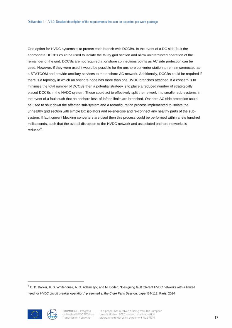
One option for HVDC systems is to protect each branch with DCCBs. In the event of a DC side fault the
appropriate DCCBs could be used to isolate the faulty grid section and allow uninterrupted operation of the
remainder of the grid. DCCBs are not required at onshore connections points as AC side protection can be
used. However, if they were used it would be possible for the onshore converter station to remain connected as
a STATCOM and provide ancillary services to the onshore AC network. Additionally, DCCBs could be required if
there is a topology in which an onshore node has more than one HVDC branches attached. If a concern is to
minimise the total number of DCCBs then a potential strategy is to place a reduced number of strategically
placed DCCBs in the HVDC system. These could act to effectively split the network into smaller sub-systems in
the event of a fault such that no onshore loss-of-infeed limits are breeched. Onshore AC side protection could
be used to shut down the affected sub-system and a reconfiguration process implemented to isolate the
unhealthy grid section with simple DC isolators and re-energise and re-connect any healthy parts of the sub-
system. If fault current blocking converters are used then this process could be performed within a few hundred
milliseconds, such that the overall disruption to the HVDC network and associated onshore networks is
reduced5.
5 C. D. Barker, R. S. Whitehouse, A. G. Adamczyk, and M. Boden, "Designing fault tolerant HVDC networks with a limited
need for HVDC circuit breaker operation," presented at the Cigré Paris Session, paper B4-112, Paris, 2014

Deliverable 1.1, V1.0: Detailed description of the requirements that can be expected per work package
18
11 Figure: Asymmetric monopole
2.3.1.3 CONVERTER CONFIGURATION OPTIONS
Another consideration, which has a large impact on the performance and operation of an offshore HVDC grid, is
the configuration of converters and cables used. There are a number of different options available as outlined
below.
Asymmetric Monopole
An asymmetric monopole grid configuration operates with one HVDC cable and an earthed return. It is possible
to realise an asymmetric monopole using a single cable with a real earth return but this is prohibited in some
countries and faces environmental objections in others, so a solidly earthed low voltage return cable is normally
required as illustrated in Figure 116.
6 Figures 10-13 are derived with reference to Cigré Working Group B4-52, Technical Brochure, "HVDC Grid Feasibility Study",
2013 and S. De Boeck, P. Tielens, W. Leterme, and D. Van Hertem, "Configurations and earthing of HVDC grids," in Power
and Energy Society General Meeting (PES), 2013 IEEE, 2013, pp. 1-5.
Deliverable 1.1, V1.0: Detailed description of the requirements that can be expected per work package
19
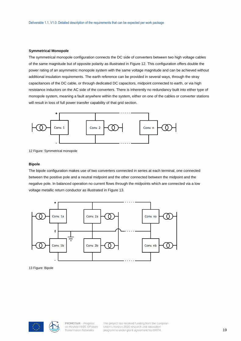
12 Figure: Symmetrical monopole
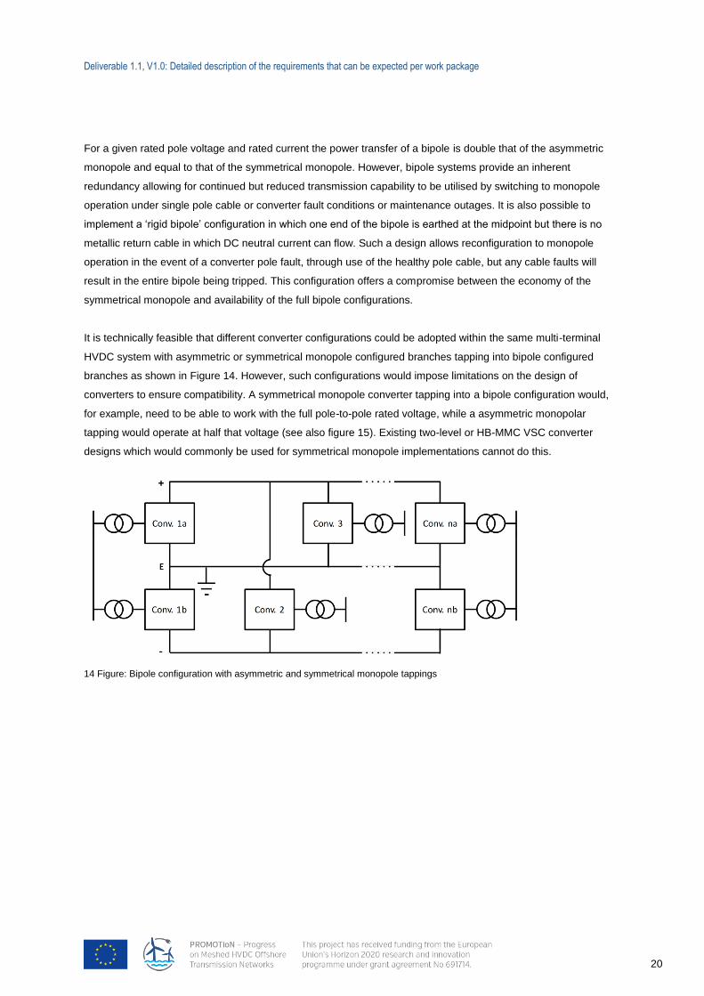
13 Figure: Bipole
Symmetrical Monopole
The symmetrical monopole configuration connects the DC side of converters between two high voltage cables
of the same magnitude but of opposite polarity as illustrated in Figure 12. This configuration offers double the
power rating of an asymmetric monopole system with the same voltage magnitude and can be achieved without
additional insulation requirements. The earth reference can be provided in several ways, through the stray
capacitances of the DC cable, or through dedicated DC capacitors, midpoint connected to earth, or via high
resistance inductors on the AC side of the converters. There is inherently no redundancy built into either type of
monopole system, meaning a fault anywhere within the system, either on one of the cables or converter stations
will result in loss of full power transfer capability of that grid section.
Bipole
The bipole configuration makes use of two converters connected in series at each terminal, one connected
between the positive pole and a neutral midpoint and the other connected between the midpoint and the
negative pole. In balanced operation no current flows through the midpoints which are connected via a low
voltage metallic return conductor as illustrated in Figure 13.
Deliverable 1.1, V1.0: Detailed description of the requirements that can be expected per work package
20
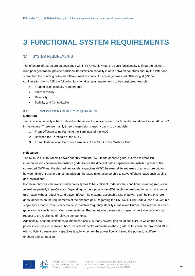
14 Figure: Bipole configuration with asymmetric and symmetrical monopole tappings
For a given rated pole voltage and rated current the power transfer of a bipole is double that of the asymmetric
monopole and equal to that of the symmetrical monopole. However, bipole systems provide an inherent
redundancy allowing for continued but reduced transmission capability to be utilised by switching to monopole
operation under single pole cable or converter fault conditions or maintenance outages. It is also possible to
implement a ‘rigid bipole’ configuration in which one end of the bipole is earthed at the midpoint but there is no
metallic return cable in which DC neutral current can flow. Such a design allows reconfiguration to monopole
operation in the event of a converter pole fault, through use of the healthy pole cable, but any cable faults will
result in the entire bipole being tripped. This configuration offers a compromise between the economy of the
symmetrical monopole and availability of the full bipole configurations.
It is technically feasible that different converter configurations could be adopted within the same multi-terminal
HVDC system with asymmetric or symmetrical monopole configured branches tapping into bipole configured
branches as shown in Figure 14. However, such configurations would impose limitations on the design of
converters to ensure compatibility. A symmetrical monopole converter tapping into a bipole configuration would,
for example, need to be able to work with the full pole-to-pole rated voltage, while a asymmetric monopolar
tapping would operate at half that voltage (see also figure 15). Existing two-level or HB-MMC VSC converter
designs which would commonly be used for symmetrical monopole implementations cannot do this.
Deliverable 1.1, V1.0: Detailed description of the requirements that can be expected per work package
21
3 FUNCTIONAL SYSTEM REQUIREMENTS
3.1 SYSTEM REQUIREMENTS
The offshore infrastructure as envisaged within PROMOTioN has the basic functionality to integrate offshore
wind park generation, provide additional transmission capacity in or in between countries and, by the latter one,
strengthen the coupling between different market zones. An envisaged meshed offshore grid (MOG)
configuration has to fulfil the following functional system requirements to be considered feasible:
Transmission capacity requirements
Interoperability
Reliability
Stability and Controllability
3.1.1 TRANSMISSION CAPACITY REQUIREMENTS
Definition
Transmission capacity is here defined as the amount of active power, which can be transferred via an AC or DC
infrastructure. There are mainly three transmission capacity paths to distinguish:
1. From Offshore Wind Farms to the Terminals of the MOG
2. Between the Terminals of the MOG
3. From Offshore Wind Farms or Terminals of the MOG to the Onshore Grid
Relevance
The MOG is built to transmit power not only from the OWF to the onshore grids, but also to establish
interconnections between the onshore grids. Hence the different paths depend on the installed power of the
connected OWF and the desired net transfer capacities (NTC) between different areas of an onshore grid or
between different onshore grids. In addition, the MOG might also be able to serve offshore loads such as oil &
gas installations.
For these purposes the transmission capacity has to be sufficient under normal conditions, meaning (n-0)-case,
as well as partially in (n-k)-cases. Depending on the topology the MOG might be designed to resist minimum a
(n-1)-case without reducing wind power infeed. The maximal acceptable loss of power, seen by the onshore
grids, depends on the requirements of the onshore grid. Regarding the ENTSO-E Grid Code a loss of 3 GW in a
single synchronous zone is acceptable to maintain frequency stability in mainland Europe. The maximum loss of
generation is smaller in smaller power systems. Redundancy in transmission capacity has to be sufficient with
respect to the resilience of relevant components.
Additionally, onshore limitations to infeed can occur. Already several grid situations exist, in which the OWF
power infeed has to be limited, because of bottlenecks within the onshore grids. In this case the proposed MOG
with sufficient transmission capacities is able to control the power flow and send the power to a different
onshore grid connection.

Deliverable 1.1, V1.0: Detailed description of the requirements that can be expected per work package
22
Dedicated Requirements
Finally the MOG needs sufficient transmission capacity for various purposes. How much capacity is considered
sufficient, is a matter of economic optimization (WP 7). Here the connected installed wind power and the desired
NTCs between the participating onshore grids have to be specified. Beside an economic optimum and possible
reduced transmission capacities in (n-k)-cases, the onshore grid requirements, e.g. maximal acceptable loss of
power, constrain the reduction of the capacities. Therefore the requirements for the transmission capacity
redundancy, depending on the topology and reliability are linked to the onshore requirements.
Deliverable 1.1, V1.0: Detailed description of the requirements that can be expected per work package
23
3.1.2 INTEROPERABILITY
Definition
Interoperability of the MOG describes the possibility to integrate different types of devices from different vendors
into the MOG without compromising the expected behavior of the system. Although the technical development
of technologies (e.g. converter technologies) proceeds fast, operation of new technologies together with existing
and installed technologies must be possible for the grid operators. Furthermore the use of components
providing the same technological functionality provided by different manufacturers must be possible within a
common grid (so called, multivendor capability). Thereby it can be ensured that grid operators are not bound to
only one manufacturer. Interoperability is not just a market and monopoly-control requirement, it is also
inevitable if MOG similar in scale to HVAC grids (which consist of components supplied by multiple vendors) are
to be realized. To ensure the interoperability a minimum set of system interfaces have to be defined for each
component in order to enable a third party to develop components that can seamlessly integrate into the
system.
Relevance
Interoperability assures that grid operators are able to choose dependent on the market situation and the
technological advancement and are not obliged to one specific manufacturer or technology. Thus,
interoperability is one major aspect that ensures a timely progress of the development of the MOG.
Dedicated Requirements
Assuring interoperability requires the definition of specific interfaces. These interfaces need to be followed by all
manufacturers in order to achieve a stable and safe operating MOG. The interfaces can be divided in two
groups:
Technical interfaces:
This interface group covers the technical data, which have to be exchanged for the operation between
each HVDC station and the grid operator. Exemplarily, this includes data such as maximum current,
frequency or power range requirements according to the relevant grid code (e.g. extension of the
ENTSO-E Draft Network Code on High Voltage Direct Current Connections and DC-connected Power
Park Modules).
Communication interfaces:
In order to change operating points or to exchange protection related information of the converter (e.g.
synchronisation of fault handling schemes), a specific communication protocol has to be followed,
which needs to be defined by standardization or grid code e.g. with respect to allowed communication
technologies and communication speed requirements.

Deliverable 1.1, V1.0: Detailed description of the requirements that can be expected per work package
24
3.1.3 RELIABILITY
Definition
The reliability of an offshore grid is its ability to continuously perform its two main missions in normal as well as
in relevant fault cases7:
evacuate the generated power from offshore wind farms to onshore grids and
transfer power between different onshore grids
The reliability of an offshore grid can be decomposed into the two concepts of adequacy and security. The
adequacy relates to the existence of sufficient facilities within the offshore grid to perform the two missions, in
the presence of scheduled and unscheduled outages, but in steady-state conditions. The security relates to the
ability of the system to withstand disturbances arising from faults and unscheduled removal of equipment.
Reliability requirements can be based on deterministic criteria (e.g. N-1 security rule) and/or on probabilistic
criteria. In particular, in a probabilistic framework, the energy delivered to shore, or transported between
countries or different onshore grids, considering a lifetime of expected fault conditions can be used as a
measure of reliability of a certain grid design.
Relevance
The reliability of the grid is influenced amongst others by the redundancy of the grid layout, the manner in which
the grid is operated and controlled, the chosen protection philosophy and the reliability of the components.
A meshed grid topology could fulfil the aspects of adequacy and security. In case of the loss of a component,
the power flow can be rerouted through the grid and still be delivered to shore if sufficient transmission capacity
for rerouting is available. The sufficient transmission capacity is mainly required by the constraints given by the
connected onshore grid.
The chosen protection philosophy influences the reliability in various ways and depends itself on the chosen
breaker and converter technology. Depending on the chosen philosophy e.g. the size of the grid part that will be
disconnected in case of a fault and the corresponding time frame that it will remain disconnected vary.
For the probabilistic calculation of the reliability of the MOG, the reliability of each component (e.g. mean time
to failure and mean time to repair) will be considered. Within PROMOTioN suitable grid layouts and
corresponding protection philosophies need to be developed which assure an adequate level of reliability.
Dedicated requirements
The required reliability of the MOG depends on the desired transmission capacities to evacuate wind power
fulfilling the constraints of the connected onshore grids. Secondarily the reliability might be fulfilling the offshore
loads with regard to the allowable size, frequency and timespan of outages. In the future the combined reliability
of the AC- and DC-grid might be worth considering. As it is the case with the transmission capacity the final
level of reliability is again a question of economical optimization and onshore grid constraints.
7 Other benefits, such as supporting onshore AC grids, or supplying off-shore loads might also be relevant
Deliverable 1.1, V1.0: Detailed description of the requirements that can be expected per work package
25
3.1.4 STABILITY AND CONTROLLABILITY
Definition
In general power system stability is defined as “the ability of an electric power system, for a given initial
operating condition, to regain a state of operating equilibrium after being subjected to a physical disturbance,
with most system variables bounded so that practically the entire system remains intact”. Within this definition
the stability framework distinguishes between small disturbance stability and large disturbance stability.
Small signal stability refers to the ability of the system to operate reliably in non-fault conditions and
remain in equilibrium when subjected to small deviations from the operating point such as changes in
wind power generation or small voltage dips. Small signal stability usually relates to a sufficient
damping of the system. Since power systems are continually subjected to load changes, a power
system must be able to adjust to changes in the power balance. If the energy balance is not ensured
within the system, the system cannot sustain a stable operation.
Large disturbance stability relates to the behaviour of the system in a faulted condition when subjected
to severe disturbances such as short circuits or loss of a significant component (e.g. large generator).
After clearing the fault the system has to return into a (new) equilibrium. Large disturbances stability
always refers to specific contingency scenarios with a reasonable likelihood of occurrence due to the
fact that it is not feasible to design a power system in a way that it can withstand every possible
relevant disturbance.
The aspects of stability have to be considered on the DC grid within all converters ant its controllers as well as
on the offshore wind farms. Furthermore the stability of the onshore grid may not be threatened for relevant
outages in the total offshore grid.
Relevance
In an AC grid the system frequency relates to the energy balance of the system. The deviation in system
frequency is dependent of the energy stored in the rotating mass of the synchronous generators. In contrast, the
energy in a DC grid is stored in the DC cable/line and converter capacitances of the system. Hence, the DC
voltage is an indicator of the energy balance. Thus, if the MOG is subjected to a disturbance the DC voltage will
be affected. Due to the small time constants, a small variation of the power will quickly lead to a change of the
DC voltage. Consequently, the DC voltage must be kept within defined boundaries and stay fixed in the short
term to secure a stable operation of the MOG. The stability of control has to be ensured to avoid counteraction
of voltage controllers of different converter stations; otherwise a stable operation point cannot be sustained.
VSC-HVDC converters allow an operation in all four quadrants of the power curve. The converters can provide
fast dynamic support to adjacent AC grids. The DC grid can thereby support the overall system stability by
providing reactive power to adjacent AC grids and thus mitigate the impact of a nearby AC fault without
influencing the DC voltage. This is valid not only for the offshore wind farms but also for the AC onshore grid. In
addition oscillations of the AC grid can be damped by providing active power to the grid.
Deliverable 1.1, V1.0: Detailed description of the requirements that can be expected per work package
26
Dedicated Requirements
For relevant outages, the whole system has to be capable to return into a (new) equilibrium. Therefore special
requirements for all relevant components, e.g. wind turbines, converters, have to be specified, how to behave in
case of different AC or DC outages. This includes especially fault-ride-through (FRT) requirements in order not
to threaten system stability in case of a severe fault. Depending on the fault, the offshore wind farms and the
converters have to withstand the fault-conditions and have to remain connected to support the system. In
addition it needs to be made sure that ancillary services to the AC grid will be provided as required in the grid
codes so that the stability of the AC system is not jeopardized.
Furthermore the stability of control has to be assured for every relevant outage. The controller affecting the
states in AC offshore and DC grid in steady-state and fault case may not act against each other.
3.2 DISCUSSION OF SYSTEM REQUIREMENTS
Some of the above mentioned requirements do not only have a functional component but are strongly
influenced by economic consideration, e.g.: The higher the redundancy of the grid the higher the reliability. But
at the same time the costs are increasing. Therefore a trade-off between the level of reliability and the financial
investment has to be made. The required level of reliability mainly depends on the requirements which the
onshore AC grid imposes on the DC grid.
Deliverable 1.1, V1.0: Detailed description of the requirements that can be expected per work package
27
4 MESHED OFFSHORE GRID – ONSHORE AC
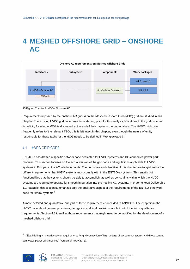
15 Figure: Chapter 4: MOG - Onshore AC
Requirements imposed by the onshore AC grid(s) on the Meshed Offshore Grid (MOG) grid are studied in this
chapter. The existing HVDC grid code provides a starting point for this analysis, limitations to the grid code and
its validity for a large MOG is discussed at the end of the chapter in the gap analysis. The HVDC grid code
frequently refers to 'the relevant TSO', this is left intact in this chapter, even though the nature of entity
responsible for these tasks for the MOG needs to be defined in Workpackage 7.
4.1 HVDC GRID CODE
ENSTO-e has drafted a specific network code dedicated for HVDC systems and DC-connected power park
modules. This section focuses on the actual version of the grid code and regulations applicable to HVDC
systems in Europe, at the AC interface points. The outcomes and objective of this chapter are to synthesize the
different requirements that HVDC systems must comply with in the ENTSO-e systems. This entails both
functionalities that the systems should be able to accomplish, as well as constraints within which the HVDC
systems are required to operate for smooth integration into the hosting AC systems. In order to keep Deliverable
1.1 readable, this section summarizes only the qualitative aspect of the requirements of the ENTSO-e network
code for HVDC systems.8
A more detailed and quantitative analysis of these requirements is included in ANNEX 3. The chapters in the
HVDC code about general provisions, derogation and final provisions are left out of the list of qualitative
requirements. Section 4.3 identifies those requirements that might need to be modified for the development of a
meshed offshore grid.
8 : “Establishing a network code on requirements for grid connection of high voltage direct current systems and direct-current
connected power park modules” (version of 11/09/2015).
Onshore AC requirements on Meshed Offshore Grids
Work PackagesComponentsInterfaces
4. MOG – Onshore AC
WP 1, task 1.2
HVDC code
Subsystem
4.1 Onshore Convertor WP 2 & 3
Deliverable 1.1, V1.0: Detailed description of the requirements that can be expected per work package
28
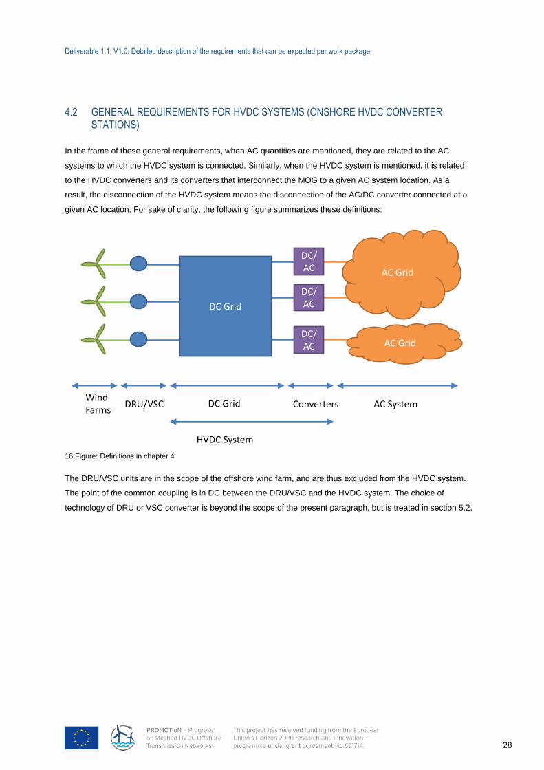
4.2 GENERAL REQUIREMENTS FOR HVDC SYSTEMS (ONSHORE HVDC CONVERTER STATIONS)
In the frame of these general requirements, when AC quantities are mentioned, they are related to the AC
systems to which the HVDC system is connected. Similarly, when the HVDC system is mentioned, it is related
to the HVDC converters and its converters that interconnect the MOG to a given AC system location. As a
result, the disconnection of the HVDC system means the disconnection of the AC/DC converter connected at a
given AC location. For sake of clarity, the following figure summarizes these definitions:
16 Figure: Definitions in chapter 4
The DRU/VSC units are in the scope of the offshore wind farm, and are thus excluded from the HVDC system.
The point of the common coupling is in DC between the DRU/VSC and the HVDC system. The choice of
technology of DRU or VSC converter is beyond the scope of the present paragraph, but is treated in section 5.2.
DC Grid
AC Grid
DC/AC
DC/AC
DC/AC AC Grid
ConvertersDC Grid
HVDC System
AC SystemDRU/VSCWindFarms
Deliverable 1.1, V1.0: Detailed description of the requirements that can be expected per work package
29
4.2.1 REQUIREMENTS FOR ACTIVE POWER CONTROL AND FREQUENCY SUPPORT
4.2.1.1 FREQUENCY RANGE
The HVDC systems must be capable of operating within a specified frequency range. The frequency range
values might vary between the different synchronous AC areas.
4.2.1.2 FREQUENCY RATE OF CHANGE
The HVDC system must be capable of withstanding specified AC system frequency rates of change (measured
at any point in time as an average of the rate of frequency for the previous 1s).
4.2.1.3 REQUIREMENTS RELATED TO FREQUENCY CONTROL
The AC/DC converters of the HVDC system must be equipped with an independent control mode to modulate
the active power output of the HVDC converter station according to the frequencies at all connection points of
the HVDC system to maintain stable system frequencies and/or contribute to the frequency control of the AC
system. The detailed operating principle, associated performance parameters and activation criteria of this
frequency control must be specified.
The HVDC systems must be capable of operating in the following three control modes:
Frequency Sensitive Mode (FSM)
Limited Frequency Sensitive Mode – Overfrequency (LFSM-O)
Limited Frequency Sensitive Mode – Underfrequency (LFSM-U)
The following parameters for these control loops are to be specified by the TSO, within certain bounds
mentioned in the network code:
Frequency response deadband
Upward droop value
Downward droop value
Frequency response insensitivity
Initial delay of activation
Deliverable 1.1, V1.0: Detailed description of the requirements that can be expected per work package
30
4.2.1.4 ACTIVE POWER CONTROLLABILITY, CONTROL RANGE AND RAMPING RATE
The requirements associated to the HVDC system ability to receive instructions and active power set points and
reacting accordingly are as follows:
Ability to control the active power up to the maximum power in both directions
Maximum allowed increase or decrease of power setpoint specified for adjusting the transmitted active
power
Minimum active power transmission capacity for each direction, below which the active power
transmission power capacity is not requested
Maximum time delay between receipt of the TSO request and start of the active power level
adjustment;
Adjustment of the ramping rate, the ramping rate does not apply in case of fast power reversal or in
case of disturbance to the AC system
Possibility to take remedial actions such as stopping the ramping and blocking the Frequency Sensitive
Mode (FSM), with triggering criteria to be specified by the TSO
Fast response in case of disturbance on the AC network, with a maximum allowed delay from receiving
the triggering signal by the relevant TSO
For systems linking different AC control areas or synchronous areas, the HVDC system must be
equipped with control functions enabling the relevant TSOs to modify the transmitted active power for
the purpose of cross-border balancing
The control functions of an HVDC system must be capable of taking automatic remedial actions,
including, but not limited to, stopping the ramping and blocking of the frequency control
4.2.1.5 SYNTHETIC INERTIA
The HVDC system must be capable of providing synthetic inertia support in response to frequency changes in
one or more AC networks, activated in low and/or high frequency regimes by rapidly adjusting the active power
injected to or withdrawn from the AC networks in order to limit the rate of change of frequency (ROCOF).
For an HVDC system connecting a power park module the adjustment of active power frequency response must
be limited by the capability of the DC-connected power park modules.
4.2.1.6 MAXIMUM LOSS OF ACTIVE POWER INFEED
The HVDC system must be designed in such a way that the maximum loss of active power infeed in a
synchronous area be limited to a value specified by the relevant TSOs. The time dimension must be considered
and differentiation between temporary and permanent losses of power must be made. This has implications on
the design and the topology of the HVDC system as well as on the DC protection system.
Where an HVDC system connects two or more control areas, the relevant TSOs must consult each other in
order to set a coordinated value of the maximum loss of active power injection, taking into account common
mode failures.
Deliverable 1.1, V1.0: Detailed description of the requirements that can be expected per work package
31
4.2.2 REQUIREMENTS FOR REACTIVE POWER CONTROL AND VOLTAGE SUPPORT
4.2.2.1 VOLTAGE RANGE
The HVDC system should be able to remain connected to the system for given AC voltage range requirements.
They are dependent on the voltage level of the connection point as well as the synchronous area.
An HVDC system must be capable of automatic disconnection at connection point voltages specified by the
relevant TSO.
4.2.2.2 REACTIVE POWER CAPABILITY
The relevant HVDC system, in coordination with the relevant TSOs, must specify the reactive power capability
requirements at the connection points, in the context of varying AC voltage. The proposal for those
requirements must include a U-Q/Pmax-profile, within the boundary of which the HVDC converter station must
be capable of providing reactive power at its maximum HVDC active power transmission capacity.
4.2.2.3 REACTIVE POWER EXCHANGED WITH THE AC SYSTEM
The HVDC system must ensure that the reactive power of its HVDC converter station exchanged with the
network at the connection point is limited to specified values.
The reactive power variation caused by the reactive power control mode operation of the HVDC converter
Station, must not result in a voltage step exceeding the allowed value at the AC connection point.
4.2.2.4 REACTIVE POWER CONTROL MODE
Three control modes must be possible:
Voltage control mode;
Reactive power control mode;
Power factor control mode.
In voltage control mode, a dead-band around the 1p.u. value may be enforced (adjustable by the TSO). Certain
time requirements are enforced relating to rise time (time required to reach 90% of the reference value) and
settling time (time required to settle within a certain tolerance of the AC voltage set point, defined by the relevant
TSO).
Voltage control also has to include the possibility of providing reactive power output control through two set
points, for voltage and reactive power respectively. Remote selection of the control mode and associated set
points has to be foreseen. Maximum steps in the reference signals should be enforced to limit the disturbances
to the grid.
4.2.2.5 PRIORITY TO ACTIVE POWER OR REACTIVE POWER CONTRIBUTIONS
The relevant TSO will determine whether active or reactive power contribution has priority during low or high
voltage operation and during faults for which fault-ride-through capability is required. If priority is given to active
power contribution, its provision must be established within a time from the fault inception as specified by
relevant TSO.
Deliverable 1.1, V1.0: Detailed description of the requirements that can be expected per work package
32
4.2.2.6 POWER QUALITY
The relevant TSO must define maximum level of distortion allowed from the HVDC installation at the point of
common coupling.
4.2.3 REQUIREMENTS FOR FAULT RIDE THROUGH CAPABILITY
4.2.3.1 FAULT RIDE THROUGH CAPABILITY
The relevant TSO specifies a voltage-against-time profile at the connection point, above which the HVDC
converter station must be capable of staying connected and continue stable operation. The pre-fault and post-
fault conditions to be used for the (Low Voltage Ride Through) LVRT capabilities are to be provided by the TSO.
The TSO may specify voltages (Ublock) at the connection points under specific network conditions whereby the
HVDC system is allowed to block. The relevant TSO must specify fault-ride-through capabilities in case of
asymmetrical faults.
4.2.3.2 SHORT CIRCUIT CONTRIBUTION DURING FAULTS
The HVDC system is required to have the capability of providing fast fault current at a connection point in case
of symmetrical three-phase fault, if and as specified by the TSO. The following characteristics are then
specified:
Conditions for activating the fault current contribution;
Characteristics of the fast fault current;
Timing and accuracy of the fast fault current, which may include several stages.
A requirement for asymmetrical current injection in the case of asymmetrical faults is specified by the TSO (1-
phase or 2-phase).
4.2.3.3 POST-FAULT ACTIVE POWER RECOVERY
The relevant TSO must specify the magnitude and time profile of active power recovery that the HVDC system
must be capable of providing to the AC system.
4.2.3.4 RECOVERY FROM DC FAULTS
HVDC systems, including DC overhead lines and cables, must be capable of clearing and isolating the DC fault
and fast recovery from transient faults within the HVDC system. Details of this capability must be subject to
coordination and agreements on protection schemes and settings.
Deliverable 1.1, V1.0: Detailed description of the requirements that can be expected per work package
33
4.2.4 REQUIREMENTS FOR CONTROL
4.2.4.1 ENERGIZATION AND SYNCHRONIZATION
Limits on acceptable transients on the AC system during these operations must be enforced by the relevant
TSO.
4.2.4.2 INTERACTION BETWEEN HVDC SYSTEMS AND OTHER AC CONNECTED PLANTS AND
EQUIPMENT
The HVDC converter controllers and filters must be designed to ensure that no negative interaction occurs
between stations and nearby electrical equipment.
The relevant TSO may specify transient levels of performance associated with events for the individual HVDC
system or collectively across commonly impacted HVDC systems. This specification may be provided to protect
the integrity of both TSO equipment and equipment of grid users in order to comply with the relevant standards
and codes.
4.2.4.3 POWER OSCILLATION DAMPING CAPABILITY
The HVDC system must be capable of contributing to the damping of power oscillations in the connected AC
systems. The connecting TSO must provide the frequency range for which damping is to be provided and final
settings for the damping controller are agreed following discussions with the connecting TSO. The introduction
of the HVDC system should not lead to un-damped oscillations and should not degrade the damping level in the
AC system.
4.2.4.4 SUB SYNCHRONOUS TORSIONAL INTERACTION DAMPING CAPABILITY
The HVDC system must be capable of contributing to electrical damping of sub-synchronous torsional
interaction (SSTI).
4.2.4.5 NETWORK CHARACTERISTICS
The relevant TSO must make available the pre-fault and post-fault conditions for calculations of the minimum
and maximum short circuit power at the connection points. The HVDC system must be capable of operating
within the range of short circuit power and network characteristics specified by the TSO.
Deliverable 1.1, V1.0: Detailed description of the requirements that can be expected per work package
34
4.2.5 REQUIREMENTS FOR PROTECTION DEVICES AND SETTINGS
4.2.5.1 PRIORITY RANKING OF PROTECTION AND CONTROL
The HVDC system protections and control devices must be organised in compliance with the following priority
ranking, in decreasing order of importance:
AC system and HVDC system protection
Active power control for support of the AC system in emergency conditions
Synthetic inertia, if applicable
Automatic remedial actions
LFSM
FSM and frequency control
Power gradient constraint
4.2.5.2 CHANGES TO PROTECTION AND CONTROL SCHEMES AND SETTINGS
The control modes and associated set points of the HVDC system must be capable of being changed remotely,
as specified by the relevant system operator, in coordination with the relevant TSO.
4.2.6 REQUIREMENTS FOR POWER SYSTEM RESTORATION
4.2.6.1 BLACK START
An HVDC system may provide black start services to a TSO. An HVDC system with black start capability must
be able, in case one converter station is energised, to energise the busbar of the AC-substation to which
another converter station is connected, within a time frame after shut down determined by the relevant TSOs.
The HVDC system must be able to synchronise within specified frequency limits and voltage limits. The black
start availability, capability and the associated operational procedure must be specified with the relevant TSO.
Deliverable 1.1, V1.0: Detailed description of the requirements that can be expected per work package
35
4.2.7 INFORMATION EXCHANGE AND COORDINATION
4.2.7.1 OPERATIONAL REQUIREMENTS OF HVDC SYSTEMS
With regard to instrumentation for the operation, each HVDC converter unit of an HVDC system must be
equipped with an automatic controller capable of receiving set points and commands from the relevant system
operator and from the relevant TSO. This automatic controller must be capable of operating the HVDC
converter units of the HVDC system in a coordinated way. The relevant system operator must specify the
automatic controller hierarchy per HVDC converter unit. The automatic controller of the HVDC system must be
capable of sending the following signals to the relevant system operator:
operational signals, providing at least the following
o start-up signals
o AC and DC voltage & current measurements
o active and reactive power measurements on the AC side
o DC power measurements
o HVDC converter unit level operation in a multi-pole type HVDC converter
o elements and topology status
o FSM, LFSM-O and LFSM-U active power ranges
alarm signals, providing at least the following
o emergency blocking
o ramp blocking
o fast active power reversal
The automatic controllers must be capable of receiving the following types of signals from the relevant system
operator
operational signals, receiving at least the following:
o start-up command
o active power set points
o frequency sensitive mode settings
o reactive power, voltage or similar set points
o reactive power control modes
o power oscillation damping control
o synthetic inertia
alarm signals, receiving at least the following:
o emergency blocking command
o ramp blocking command
o active power flow direction
o fast active power reversal command
Deliverable 1.1, V1.0: Detailed description of the requirements that can be expected per work package
36
4.3 DISCUSSION ON HVDC CODE
This chapter has extracted the most relevant qualitative grid code requirements contained in the actual HVDC
code. The quantification of these qualitative requirements is defined in the ENTSOe HVDC code. However,
further work is necessary to translate, complete and/or adapt these requirements into a multi-terminal, meshed
HVDC that could be either a net importer of active power or a net exporter of active power. Further a number of
new system behaviour should be expected from a multi-terminal meshed HVDC system as complex integrations
with the AC systems may take place. The HVDC grid code is regarded as the starting point for discussion. Any
desired change to the HVDC code will have to follow regular code drafting processes.
In line with the high level objectives of any grid code, it is anticipated that the requirements will pursue the
following objectives:
Ensure the physical security of the persons in normal and abnormal operating conditions. It is
anticipated that AC/DC converter requirements will not be different from any HVDC two terminal
converter.
Ensure that the various devices are adequately protected in normal and abnormal operating conditions.
Require that the connected equipment of a grid user do not hamper or disturb the adequate operation
of the other grid user equipment.
The following issues are expected to be discussion points in the development of the MOG in relation to the HVDC grid code:
Onshore AC grid support- Contribute to the robustness and the operational security of the AC systems.
It is anticipated that the multi-terminal and that the capability to connect wind generation will offer new
possibilities to the HVDC system. This could lead to new types of requirements that could take the form
of a wide area protection/control system seen from the AC systems.
Weak AC grids - Specify for which operating conditions the HVDC system should remain connected to
and able to operate with the AC system in steady state but also ride through AC system transients. It is
anticipated that AC/DC converter requirements will not be different from any HVDC two terminal
converter with the exception that the HVDC system converters should be able to operate in grids which
are weak relatively to its size (both with regard to frequency and voltage)
Abnormal conditions - Specify for which operating (abnormal) conditions the HVDC system must
disconnect from the AC system.
Predictability - Specify the requirements in terms of predictability of the HVDC system during normal
but also abnormal operating regimes. It is anticipated that the Promotion targeted HVDC system will
strongly differ from a ‘traditional’ HVDC two terminal system. The reasons are that a change in
operating condition may spread across the whole HVDC system and affect various HVDC converters
forcing various AC system operators to encompass the whole HVDC behaviour in their operation
procedures and processes.
Abnormal AC conditions - Specify the requirements in terms of expected HVDC system support during
abnormal operation of the AC system. It is anticipated that the targeted HVDC system will offer various

Deliverable 1.1, V1.0: Detailed description of the requirements that can be expected per work package
37
additional options (mainly related to congestion management in the AC system, frequency control and
damping of the oscillations in the AC system).
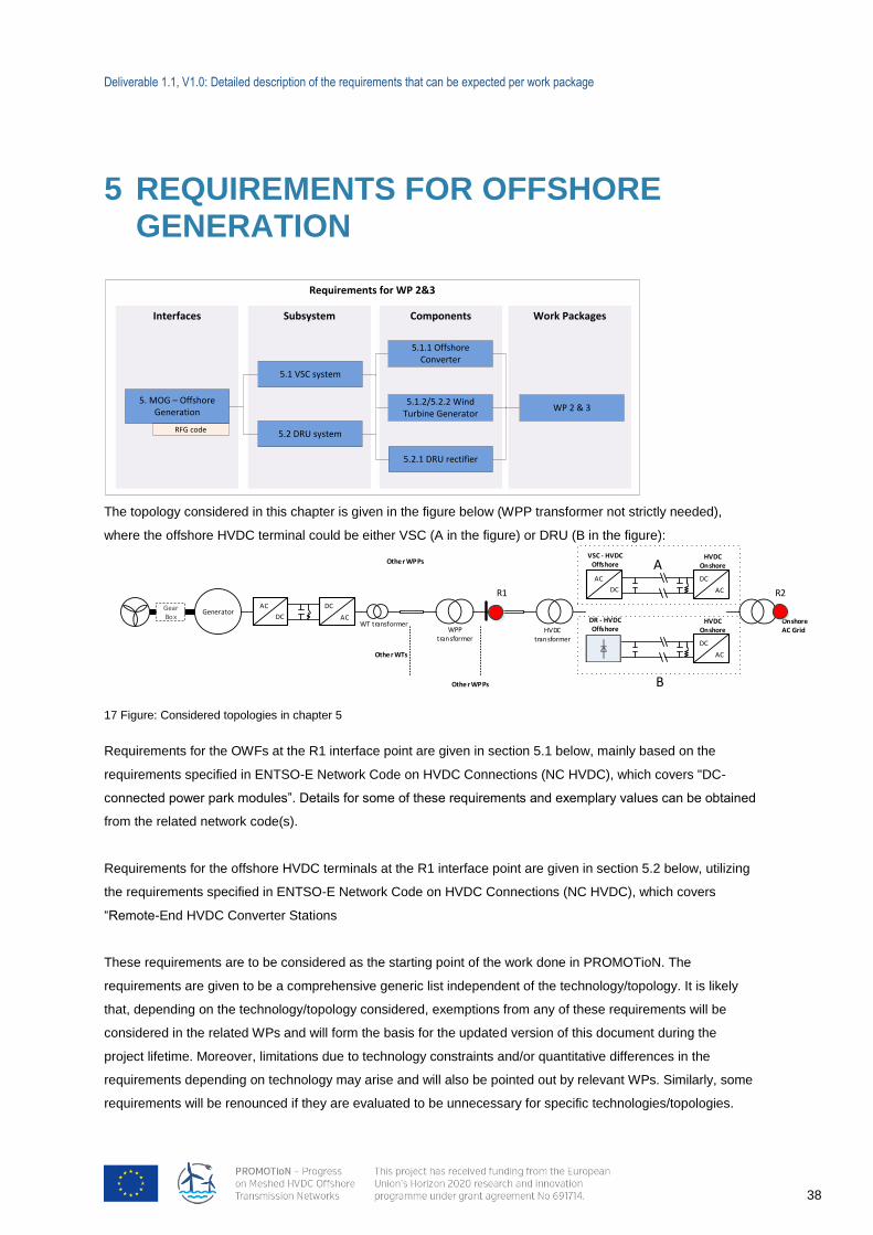
Deliverable 1.1, V1.0: Detailed description of the requirements that can be expected per work package
38
5 REQUIREMENTS FOR OFFSHORE GENERATION
The topology considered in this chapter is given in the figure below (WPP transformer not strictly needed),
where the offshore HVDC terminal could be either VSC (A in the figure) or DRU (B in the figure):
Othe r WPPs
GearBox
GeneratorAC
DC AC
DC
WT transformerWPP
transformerHVDC
transformer
Othe r WTs
Othe r WPPs
R1
AC
DC AC
DC
VSC - HVDC Offshore
HVDC Onshore
AC
DC
DR - HVDC Offshore
HVDC Onshore
Onshore AC Grid
R2
A
B
17 Figure: Considered topologies in chapter 5
Requirements for the OWFs at the R1 interface point are given in section 5.1 below, mainly based on the
requirements specified in ENTSO-E Network Code on HVDC Connections (NC HVDC), which covers "DC-
connected power park modules”. Details for some of these requirements and exemplary values can be obtained
from the related network code(s).
Requirements for the offshore HVDC terminals at the R1 interface point are given in section 5.2 below, utilizing
the requirements specified in ENTSO-E Network Code on HVDC Connections (NC HVDC), which covers
“Remote-End HVDC Converter Stations
These requirements are to be considered as the starting point of the work done in PROMOTioN. The
requirements are given to be a comprehensive generic list independent of the technology/topology. It is likely
that, depending on the technology/topology considered, exemptions from any of these requirements will be
considered in the related WPs and will form the basis for the updated version of this document during the
project lifetime. Moreover, limitations due to technology constraints and/or quantitative differences in the
requirements depending on technology may arise and will also be pointed out by relevant WPs. Similarly, some
requirements will be renounced if they are evaluated to be unnecessary for specific technologies/topologies.
Requirements for WP 2&3
Work PackagesComponentsInterfaces
5. MOG – Offshore Generation
5.2.1 DRU rectifier
5.1.1 Offshore Converter
5.1.2/5.2.2 Wind Turbine Generator
WP 2 & 3
RFG code
Subsystem
5.2 DRU system
5.1 VSC system
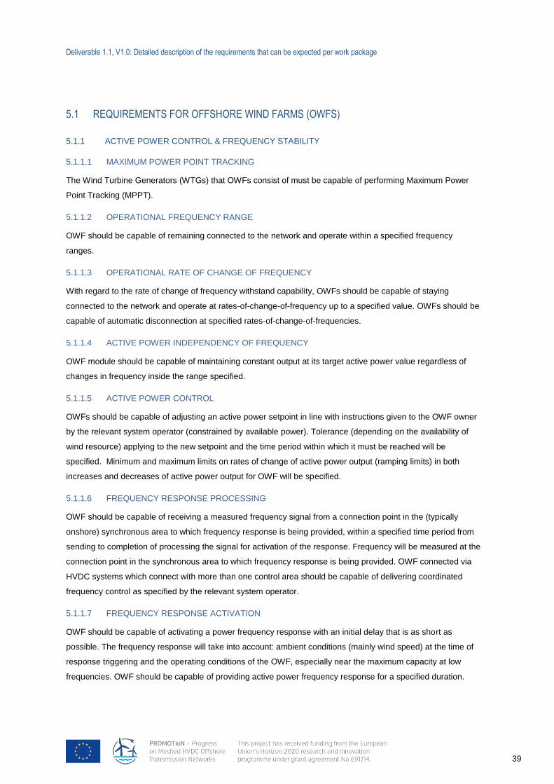
Deliverable 1.1, V1.0: Detailed description of the requirements that can be expected per work package
39
5.1 REQUIREMENTS FOR OFFSHORE WIND FARMS (OWFS)
5.1.1 ACTIVE POWER CONTROL & FREQUENCY STABILITY
5.1.1.1 MAXIMUM POWER POINT TRACKING
The Wind Turbine Generators (WTGs) that OWFs consist of must be capable of performing Maximum Power
Point Tracking (MPPT).
5.1.1.2 OPERATIONAL FREQUENCY RANGE
OWF should be capable of remaining connected to the network and operate within a specified frequency
ranges.
5.1.1.3 OPERATIONAL RATE OF CHANGE OF FREQUENCY
With regard to the rate of change of frequency withstand capability, OWFs should be capable of staying
connected to the network and operate at rates-of-change-of-frequency up to a specified value. OWFs should be
capable of automatic disconnection at specified rates-of-change-of-frequencies.
5.1.1.4 ACTIVE POWER INDEPENDENCY OF FREQUENCY
OWF module should be capable of maintaining constant output at its target active power value regardless of
changes in frequency inside the range specified.
5.1.1.5 ACTIVE POWER CONTROL
OWFs should be capable of adjusting an active power setpoint in line with instructions given to the OWF owner
by the relevant system operator (constrained by available power). Tolerance (depending on the availability of
wind resource) applying to the new setpoint and the time period within which it must be reached will be
specified. Minimum and maximum limits on rates of change of active power output (ramping limits) in both
increases and decreases of active power output for OWF will be specified.
5.1.1.6 FREQUENCY RESPONSE PROCESSING
OWF should be capable of receiving a measured frequency signal from a connection point in the (typically
onshore) synchronous area to which frequency response is being provided, within a specified time period from
sending to completion of processing the signal for activation of the response. Frequency will be measured at the
connection point in the synchronous area to which frequency response is being provided. OWF connected via
HVDC systems which connect with more than one control area should be capable of delivering coordinated
frequency control as specified by the relevant system operator.
5.1.1.7 FREQUENCY RESPONSE ACTIVATION
OWF should be capable of activating a power frequency response with an initial delay that is as short as
possible. The frequency response will take into account: ambient conditions (mainly wind speed) at the time of
response triggering and the operating conditions of the OWF, especially near the maximum capacity at low
frequencies. OWF should be capable of providing active power frequency response for a specified duration.
Deliverable 1.1, V1.0: Detailed description of the requirements that can be expected per work package
40
5.1.1.8 FREQUENCY RESPONSE PARAMETERISATION
OWFs should be able to provide active power frequency response based on a set of specified parameters which
allow for the calculation of the active power as a function of the frequency. The combination of choice of the
parameters specified should take possible technology-dependent limitations into account.
5.1.1.9 SYNTHETIC INERTIA
OWFs may be required to provide synthetic inertia. The operating principle of control systems installed to
provide synthetic inertia and the associated performance parameters will be specified by the relevant system
operator.
5.1.1.10 DC VOLTAGE RESPONSE
OWFs may be required to contribute to DC voltage response to support the HVDC grid. This is to be done in
coordination with requirements set out in Section 5.2 for HVDC Terminals and requirements must take into
account OWFs capabilities.
5.1.2 ROBUSTNESS AND CONTROL DURING SHORT-CIRCUIT FAULTS
5.1.2.1 OFFSHORE AC FAULT-RIDE-THROUGH
OWF should be capable of staying connected to the network and continuing to operate after the network has
been disturbed by securely cleared (symmetrical and asymmetrical) faults, which results in a voltage within a
specified voltage-against-time-profile at the connection point.
Under specified conditions, OWF should be capable of reconnecting to the network after an incidental
disconnection caused by a network disturbance.
In case of disconnection of the OWF from the offshore network, the OWF should be capable of quick re-
synchronisation in line with the agreed protection strategy.
5.1.2.2 POST-FAULT RECOVERY
The OWF should recover after faults while complying with: a voltage criterion when the post-fault active power
recovery begins, a minimum and maximum allowed time for active power recovery; a magnitude and accuracy
for active power recovery.
5.1.2.3 FAST FAULT CURRENT DURING OFFSHORE FAULTS
OWF should be capable of providing specified fault current at the connection point in case of symmetrical and
asymmetrical faults. The characteristics of the fault current will be specified. OWF should operate accordingly in
order not to prevent clearance of offshore AC faults by the protection system.
5.1.2.4 DC FAULT-RIDE-THROUGH
OWF should be capable of coordinating with the DC grid control protection systems in order to modify its output
during faults, provided that the DC fault can be detected by the OWF.Fault detection means and detailed
response (modification of output) of the OWF will be specified in related WPs.
Deliverable 1.1, V1.0: Detailed description of the requirements that can be expected per work package
41
5.1.2.5 ONSHORE AC FAULT-RIDE-THROUGH
OWF should be capable of modifying its output during onshore AC faults, provided that the onshore AC fault
can be detected by the OWF. Fault detection means and detailed response (modification of output) of the OWF
will be specified in related WPs.
5.1.3 VOLTAGE STABILITY
5.1.3.1 OPERATIONAL VOLTAGE RANGES
OWF should be capable of staying connected to the network and operating within the ranges of the network
voltage at the connection point, for the specified time periods.
OWF should be capable of automatic disconnection based on agreed terms and settings for automatic
disconnection.
5.1.3.2 REACTIVE POWER CONTROL
OWF should meet specified reactive power control requirements. As all requirements in this chapter,
applicability of this requirement will be dependent on technology and system operator and related WPs will
address quantification of this requirement.
5.1.4 POWER OSCILLATION DAMPING
OWF should be capable of contributing to damping power oscillations. The voltage and reactive power control
characteristics of OWF must not adversely affect the damping of power oscillations.
OWF should be able to modulate its active power output as response to a signal for provision of damping via
active power to the onshore AC grid.
5.1.5 START-UP
OWFs should be able to perform necessary control actions, in coordination with Offshore HVDC Terminal, in
order to start-up the offshore AC grid.
5.1.6 AUTO-SYNCHRONOUS OPERATION
In case there is no reference available to be synchronized with (e.g. VSC-HVDC or umbilical AC line) OWF
should be able to perform auto-synchronous operation, where the OWF forms and controls AC grid voltage in its
collector system. OWF should be able to switch between synchronous and auto-synchronous operation.
5.1.7 POWER QUALITY
OWF should ensure that their connection to the network does not result in a level of distortion or fluctuation of
the supply voltage on the network at the connection point.
Deliverable 1.1, V1.0: Detailed description of the requirements that can be expected per work package
42
5.2 REQUIREMENTS FOR OFFSHORE HVDC TERMINALS
As stated in the beginning of this chapter, requirements for offshore HVDC Terminal are specified irrespective of
the converter technology, in other words as common requirements both for the VSC-HVDC and DRU-HVDC.
For some technologies, some requirements will not be possible to meet without assistance of other
technologies, for others some requirements will simply not be relevant. This will be considered in the related
Work Packages. It should also be noted that the “Offshore HVDC Terminal” does not necessarily include only
the power electronics based units, but also the supervisory control units, which might be for instance required to
continuously communicate with the OWFs and circuit breakers.
Importantly, the requirements specified here only refer to the offshore AC side of offshore HVDC terminals. The
requirements on DC side will be specified in Section 7.1 and apply to offshore HVDC terminals too.
5.2.1 OPERATIONAL RANGES
5.2.1.1 OFFSHORE AC LINK VOLTAGE
Offshore HVDC Terminal should be capable of staying connected and operable at specified offshore AC voltage
levels. Automatic disconnection will be allowed at specified offshore AC voltage levels.
5.2.1.2 OFFSHORE AC LINK FREQUENCY
Offshore HVDC Terminal should be capable of staying connected and operable at specified offshore AC
frequency levels. Automatic disconnection will be allowed at specified frequency levels.
5.2.1.3 OFFSHORE RATE-OF-CHANGE-OF-FREQUENCY LINK
Offshore HVDC Terminal should be capable of staying connected and operable if the network frequency
changes at up to a specified rate.
5.2.1.4 OFFSHORE ACTIVE POWER EXCHANGE
Offshore HVDC Terminal should be capable of adjusting the transmitted active power up to its maximum HVDC
active power transmission capacity in each direction following an instruction.
Offshore HVDC Terminal should be capable of adjusting the ramping rate of active power variations within its
technical capabilities in accordance with instructions sent by relevant TSOs.
5.2.2 ROBUSTNESS AND STABILITY
Offshore HVDC Terminal should allow for necessary control actions to prevent or help damping electrical
oscillations in the offshore AC grid.
5.2.3 OFFSHORE BEHAVIOUR DURING SHORT-CIRCUIT FAULTS
5.2.3.1 OFFSHORE AC FAULT-RIDE-THROUGH
Offshore HVDC Terminal should stay connected when its connection point voltage stays within a specified
voltage-time series profile.
Deliverable 1.1, V1.0: Detailed description of the requirements that can be expected per work package
43
5.2.3.2 OFFSHORE HVDC TERMINAL MUST RESPONSE TO OFFSHORE AC GRID FAULTS
Offshore HVDC Terminal should have the capability to provide fault current with specified characteristics (e.g.
active/reactive positive/negative sequence) at a connection point in case of symmetrical (3-phase) and
asymmetrical faults
Offshore HVDC Terminal should behave in accordance with protection practices during offshore AC faults such
that as minimum it will not prohibit flow of fault currents at its terminals, up to its design current rating. In other
words, offshore HVDC Terminal should operate accordingly in order not to prevent clearance of offshore AC
faults by the protection system.
Offshore HVDC Terminal should be equipped with necessary schemes to protect itself against overcurrent and
overvoltage.
Offshore HVDC Terminal should be able to perform specified fault-recovery, where details of fault-recovery (e.g.
ramp-up of power, voltage) will be specified in related WPs.
5.2.4 OFFSHORE START-UP REQUIREMENTS
5.2.4.1 START-UP OF OFFSHORE AC GRID
Offshore HVDC Terminal should be able to perform necessary control actions, in coordination with OWFs,
switching (e.g. connecting and disconnecting AC umbilical line and/or the DRU in case of DRU-HVDC case) in
order to start up the offshore AC grid.
5.2.4.2 CAPABILITY TO CONTROL THE OFFSHORE AC GRID VOLTAGE
Offshore HVDC Terminal should be capable to control the offshore AC voltage either by itself, by proper
coordination with OWFs or by proper combination thereof.
5.2.4.3 OFFSHORE POWER QUALITY
Offshore HVDC Terminal characteristics should not result in a level of distortion or fluctuation of the supply
voltage or other electrical quantities in the offshore AC network, at the connection point, exceeding specified
levels.
Deliverable 1.1, V1.0: Detailed description of the requirements that can be expected per work package
44
5.3 DISCUSSION OF THE OFFSHORE GENERATION REQUIREMENTS
The requirements defined qualitatively in this chapter will have to be refined and quantified in future work of
WP1, with proper feedback from other WPs. At the time being, a number of challenges are identified in these
terms:
Some requirements may require strong link between OWF and Offshore HVDC Terminal. Hence,
requirement specification may not be straightforward for the single component. For instance, offshore
AC fault behaviour for OWFs may differ depending on whether they connect to VSC- or DRU-HVDC.
Extrapolation of current onshore requirement to offshore AC grids has usually been done, in order to
guarantee homogeneity and consistence. However, such demanding requirements may not be strictly
needed offshore and could (i) prevent utilisation of some technologies and (ii) prevent cost reduction.
Requirements should count equally towards all technological options. However, certain technologies
might have issues complying with certain requirements. This could mean two things: Either the
requirement is too strict (and not truly a requirement to the system), or the technology does not meet
the requirement. Additional investment to compensate for the weakness of the technology is of course
possible, but might take away the economic advantage.
The AC interactions with the DC will need to be managed differently by WTGs when using VSC or
DRU.
A careful and extensive evaluation of AC and DC faults scenarios will have to be performed by WPs 2,
3 and 4 in order to quantify solid requirements. This is particularly true for DC faults and offshore AC
faults
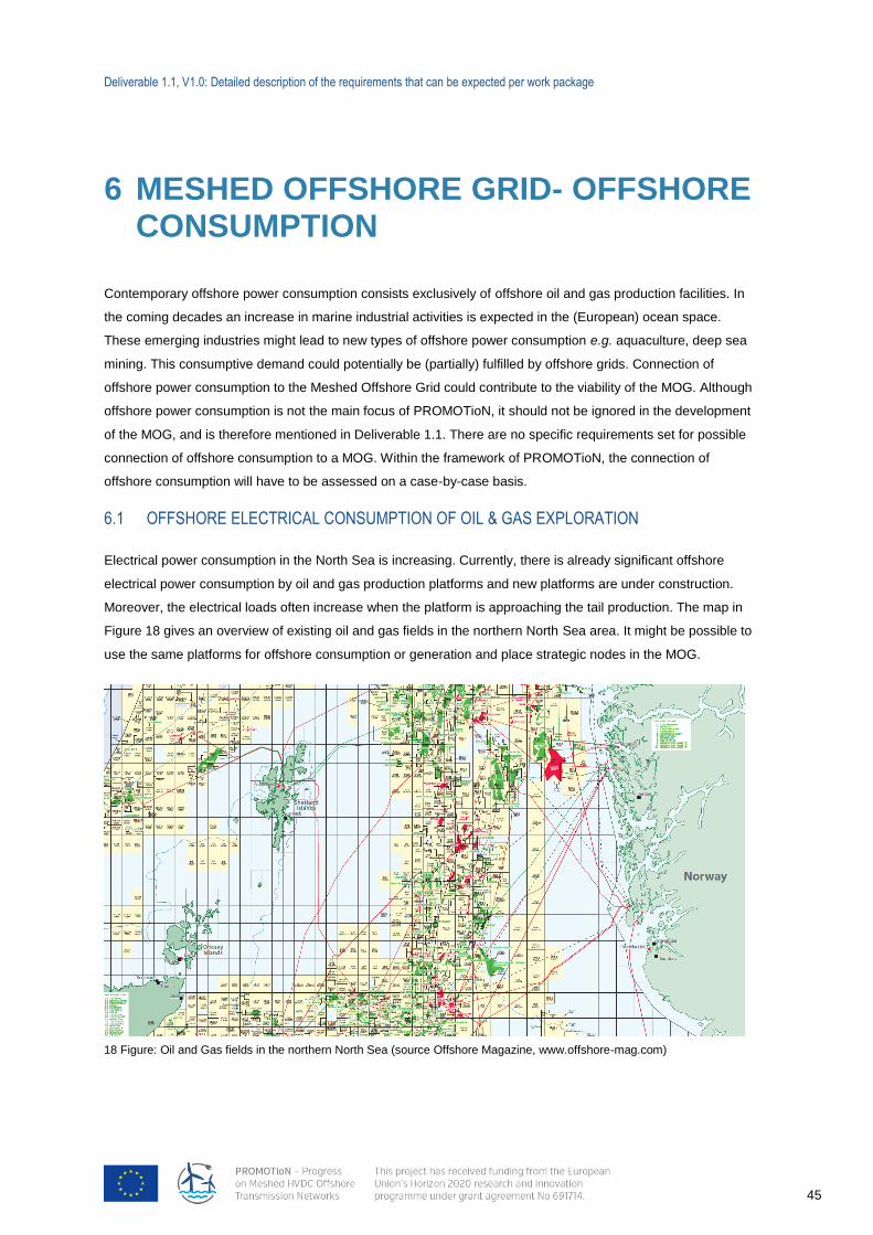
Deliverable 1.1, V1.0: Detailed description of the requirements that can be expected per work package
45
18 Figure: Oil and Gas fields in the northern North Sea (source Offshore Magazine, www.offshore-mag.com)
6 MESHED OFFSHORE GRID- OFFSHORE CONSUMPTION
Contemporary offshore power consumption consists exclusively of offshore oil and gas production facilities. In
the coming decades an increase in marine industrial activities is expected in the (European) ocean space.
These emerging industries might lead to new types of offshore power consumption e.g. aquaculture, deep sea
mining. This consumptive demand could potentially be (partially) fulfilled by offshore grids. Connection of
offshore power consumption to the Meshed Offshore Grid could contribute to the viability of the MOG. Although
offshore power consumption is not the main focus of PROMOTioN, it should not be ignored in the development
of the MOG, and is therefore mentioned in Deliverable 1.1. There are no specific requirements set for possible
connection of offshore consumption to a MOG. Within the framework of PROMOTioN, the connection of
offshore consumption will have to be assessed on a case-by-case basis.
6.1 OFFSHORE ELECTRICAL CONSUMPTION OF OIL & GAS EXPLORATION
Electrical power consumption in the North Sea is increasing. Currently, there is already significant offshore
electrical power consumption by oil and gas production platforms and new platforms are under construction.
Moreover, the electrical loads often increase when the platform is approaching the tail production. The map in
Figure 18 gives an overview of existing oil and gas fields in the northern North Sea area. It might be possible to
use the same platforms for offshore consumption or generation and place strategic nodes in the MOG.
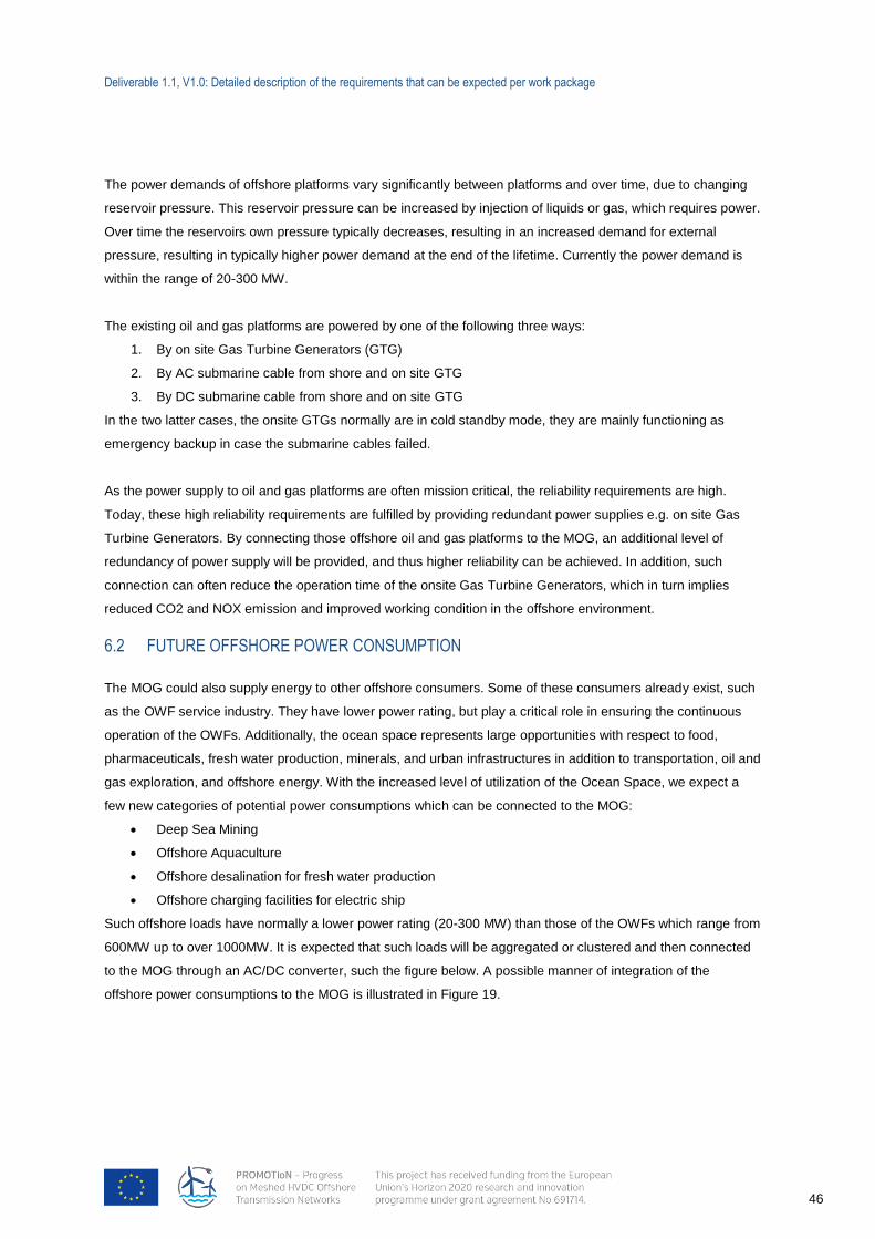
Deliverable 1.1, V1.0: Detailed description of the requirements that can be expected per work package
46
The power demands of offshore platforms vary significantly between platforms and over time, due to changing
reservoir pressure. This reservoir pressure can be increased by injection of liquids or gas, which requires power.
Over time the reservoirs own pressure typically decreases, resulting in an increased demand for external
pressure, resulting in typically higher power demand at the end of the lifetime. Currently the power demand is
within the range of 20-300 MW.
The existing oil and gas platforms are powered by one of the following three ways:
1. By on site Gas Turbine Generators (GTG)
2. By AC submarine cable from shore and on site GTG
3. By DC submarine cable from shore and on site GTG
In the two latter cases, the onsite GTGs normally are in cold standby mode, they are mainly functioning as
emergency backup in case the submarine cables failed.
As the power supply to oil and gas platforms are often mission critical, the reliability requirements are high.
Today, these high reliability requirements are fulfilled by providing redundant power supplies e.g. on site Gas
Turbine Generators. By connecting those offshore oil and gas platforms to the MOG, an additional level of
redundancy of power supply will be provided, and thus higher reliability can be achieved. In addition, such
connection can often reduce the operation time of the onsite Gas Turbine Generators, which in turn implies
reduced CO2 and NOX emission and improved working condition in the offshore environment.
6.2 FUTURE OFFSHORE POWER CONSUMPTION
The MOG could also supply energy to other offshore consumers. Some of these consumers already exist, such
as the OWF service industry. They have lower power rating, but play a critical role in ensuring the continuous
operation of the OWFs. Additionally, the ocean space represents large opportunities with respect to food,
pharmaceuticals, fresh water production, minerals, and urban infrastructures in addition to transportation, oil and
gas exploration, and offshore energy. With the increased level of utilization of the Ocean Space, we expect a
few new categories of potential power consumptions which can be connected to the MOG:
Deep Sea Mining
Offshore Aquaculture
Offshore desalination for fresh water production
Offshore charging facilities for electric ship
Such offshore loads have normally a lower power rating (20-300 MW) than those of the OWFs which range from
600MW up to over 1000MW. It is expected that such loads will be aggregated or clustered and then connected
to the MOG through an AC/DC converter, such the figure below. A possible manner of integration of the
offshore power consumptions to the MOG is illustrated in Figure 19.
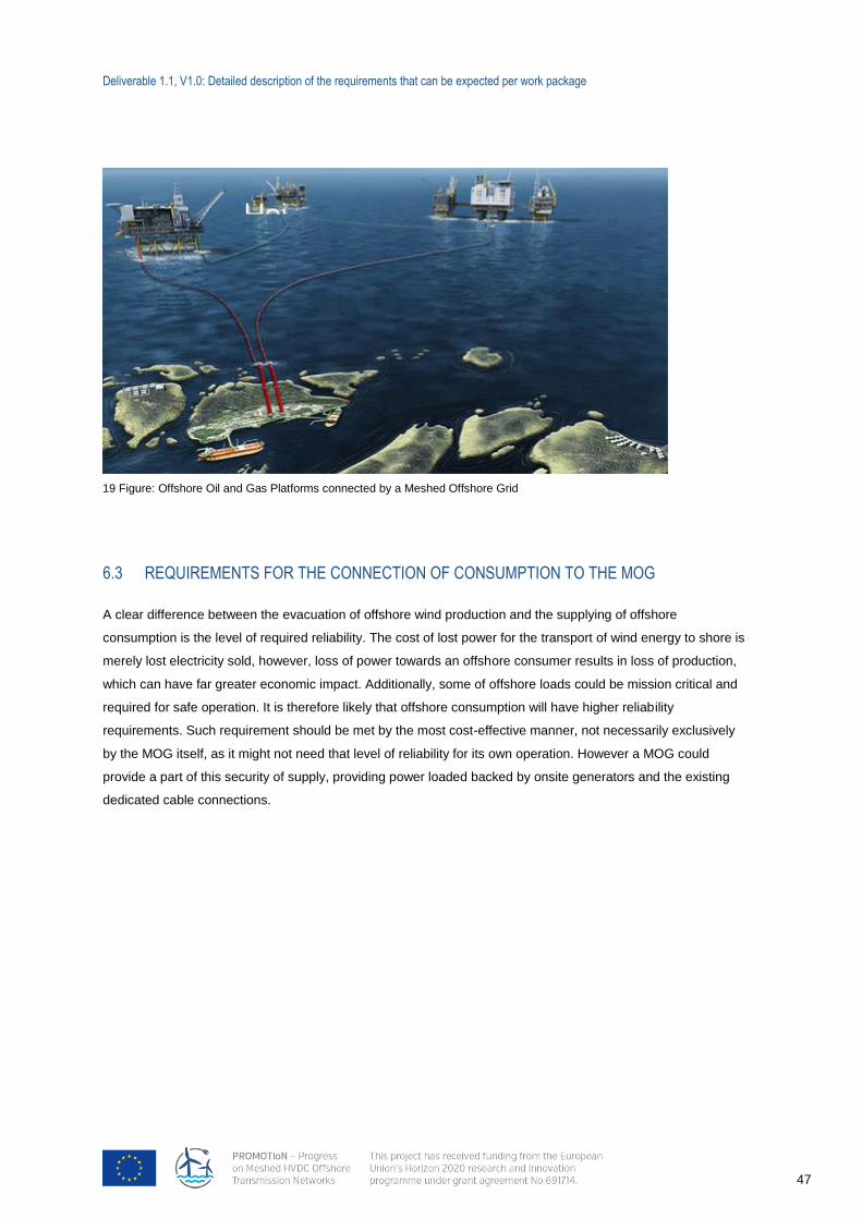
Deliverable 1.1, V1.0: Detailed description of the requirements that can be expected per work package
47
6.3 REQUIREMENTS FOR THE CONNECTION OF CONSUMPTION TO THE MOG
A clear difference between the evacuation of offshore wind production and the supplying of offshore
consumption is the level of required reliability. The cost of lost power for the transport of wind energy to shore is
merely lost electricity sold, however, loss of power towards an offshore consumer results in loss of production,
which can have far greater economic impact. Additionally, some of offshore loads could be mission critical and
required for safe operation. It is therefore likely that offshore consumption will have higher reliability
requirements. Such requirement should be met by the most cost-effective manner, not necessarily exclusively
by the MOG itself, as it might not need that level of reliability for its own operation. However a MOG could
provide a part of this security of supply, providing power loaded backed by onsite generators and the existing
dedicated cable connections.
19 Figure: Offshore Oil and Gas Platforms connected by a Meshed Offshore Grid
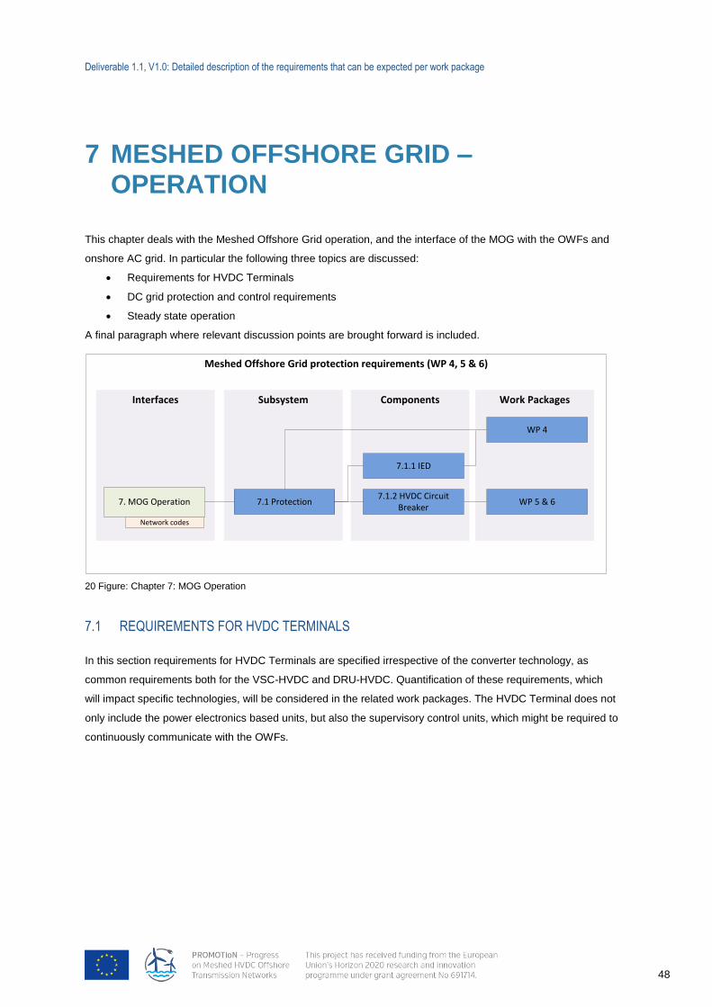
Deliverable 1.1, V1.0: Detailed description of the requirements that can be expected per work package
48
7 MESHED OFFSHORE GRID – OPERATION
This chapter deals with the Meshed Offshore Grid operation, and the interface of the MOG with the OWFs and
onshore AC grid. In particular the following three topics are discussed:
Requirements for HVDC Terminals
DC grid protection and control requirements
Steady state operation
A final paragraph where relevant discussion points are brought forward is included.
7.1 REQUIREMENTS FOR HVDC TERMINALS
In this section requirements for HVDC Terminals are specified irrespective of the converter technology, as
common requirements both for the VSC-HVDC and DRU-HVDC. Quantification of these requirements, which
will impact specific technologies, will be considered in the related work packages. The HVDC Terminal does not
only include the power electronics based units, but also the supervisory control units, which might be required to
continuously communicate with the OWFs.
Meshed Offshore Grid protection requirements (WP 4, 5 & 6)
Work PackagesComponentsInterfaces
7. MOG Operation7.1.2 HVDC Circuit
BreakerWP 5 & 6
Network codes
Subsystem
7.1 Protection
WP 4
7.1.1 IED
20 Figure: Chapter 7: MOG Operation
Deliverable 1.1, V1.0: Detailed description of the requirements that can be expected per work package
49
7.1.1 OPERATIONAL RANGES
7.1.1.1 HVDC VOLTAGE RANGE
HVDC Terminal should be capable of staying connected and operable at specified DC link voltage levels and
time periods. Automatic disconnection will be allowed at specified HVDC voltage levels.
7.1.1.2 OFFSHORE RATE OF CHANGE OF DC-VOLTAGE
HVDC Terminal should be capable of staying connected and operable if the HVDC voltage changes at up to a
specified rate.
7.1.2 POWER AND DC VOLTAGE RESPONSE
7.1.2.1 DC VOLTAGE RESPONSE PROCESSING
HVDC Terminal should be capable of receiving a measured DC voltage (or energy) signal from a connection
point, within a specified time period from sending to completion of processing the signal for activation of the
response. DC voltage will typically be measured at the HVDC Terminal’s DC side.
7.1.2.2 DC VOLTAGE RESPONSE ACTIVATION
HVDC Terminals should be capable of activating a power DC voltage response with an initial delay. HVDC
Terminals should be capable of providing active power frequency response for a specified duration.
7.1.2.3 DC VOLTAGE RESPONSE PARAMETERISATION
HVDC Terminals should be able to provide active power response based on a set of specified parameters which
allow for the calculation of the active power (or DC current) as a function of the DC voltage (or energy).
7.1.2.4 COORDINATION WITH OWFS FOR ONSHORE FREQUENCY SUPPORT
For an Offshore HVDC Terminal connecting OWFs, with regards to DC voltage response, Offshore HVDC
Terminal and OWF should agree on the technical requirements to achieve necessary support for DC voltage
response. These requirements are further described in chapter 4 and 5 of this document.
7.1.3 ROBUSTNESS AND STABILITY
HVDC Terminal should be capable of finding stable operation points for a minimum change in active power flow
and voltage level, during and after any planned or unplanned change in the HVDC system.
Deliverable 1.1, V1.0: Detailed description of the requirements that can be expected per work package
50
7.1.4 HVDC TERMINAL BEHAVIOUR DURING SHORT-CIRCUIT FAULTS
7.1.4.1 HVDC TERMINAL RESPONSE TO DC GRID FAULTS
HVDC Terminal should be equipped with necessary schemes to protect it against overcurrent and
under and overvoltage in case of DC grid faults.
HVDC Terminal should be capable of fast recovery from securely cleared faults within parts of the
meshed HVDC system (i.e. DC link faults), where details of this capability should be subject to
coordination and agreements on protection schemes and settings.
HVDC Terminal should be equipped with necessary schemes to reconnect itself after a DC grid fault.
HVDC Terminal should be equipped with necessary schemes to communicate the fault information
(e.g. fault status, DC link voltage, etc.) to OWFs which may be connected at its AC side.
7.1.5 START-UP REQUIREMENTS OF HVDC TERMINALS
7.1.5.1 START-UP OF DC GRID
HVDC Terminal should be able to perform necessary control actions in order to start-up the DC grid.
7.1.6 POWER QUALITY
HVDC Terminal operation should not exceed specified levels of distortion, fluctuation of voltage supply and
other electrical quantities at its DC side connection point.
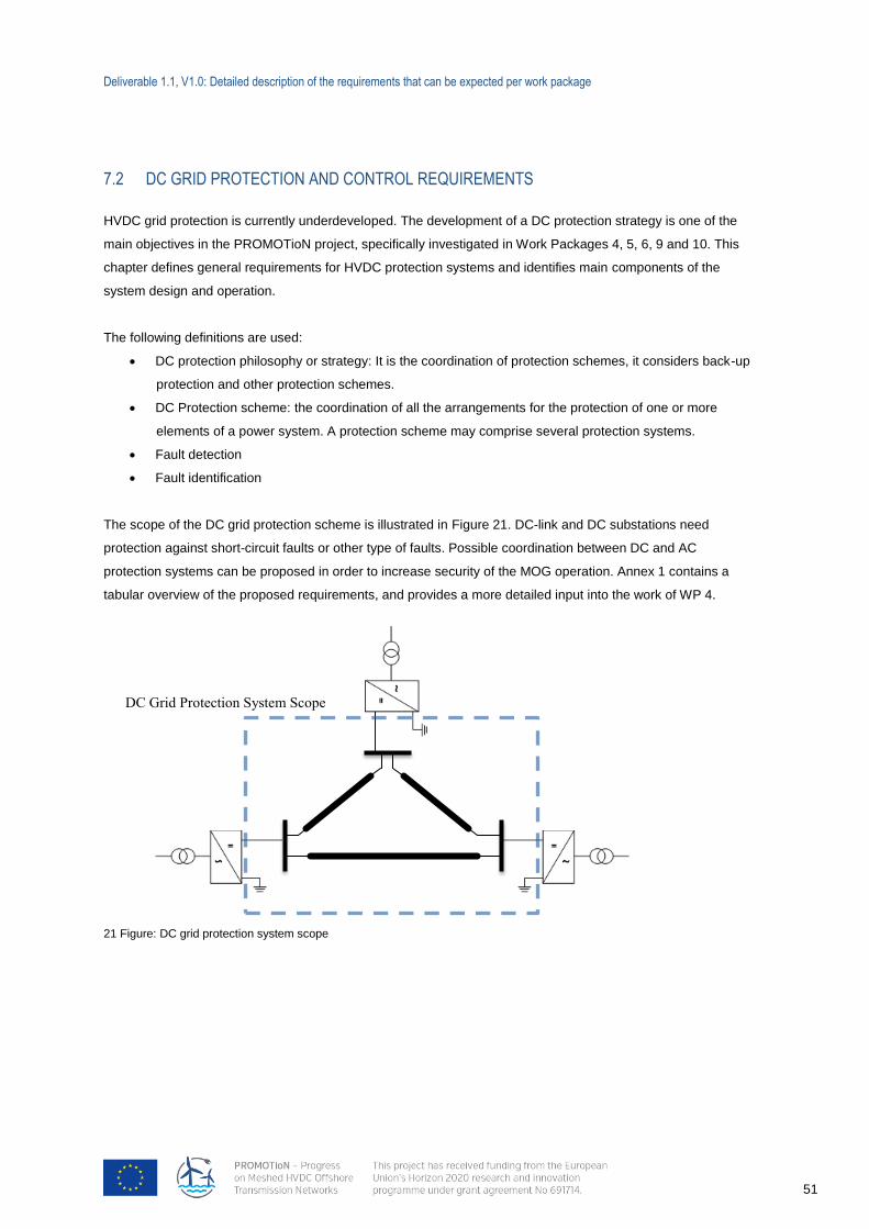
Deliverable 1.1, V1.0: Detailed description of the requirements that can be expected per work package
51
7.2 DC GRID PROTECTION AND CONTROL REQUIREMENTS
HVDC grid protection is currently underdeveloped. The development of a DC protection strategy is one of the
main objectives in the PROMOTioN project, specifically investigated in Work Packages 4, 5, 6, 9 and 10. This
chapter defines general requirements for HVDC protection systems and identifies main components of the
system design and operation.
The following definitions are used:
DC protection philosophy or strategy: It is the coordination of protection schemes, it considers back-up
protection and other protection schemes.
DC Protection scheme: the coordination of all the arrangements for the protection of one or more
elements of a power system. A protection scheme may comprise several protection systems.
Fault detection
Fault identification
The scope of the DC grid protection scheme is illustrated in Figure 21. DC-link and DC substations need
protection against short-circuit faults or other type of faults. Possible coordination between DC and AC
protection systems can be proposed in order to increase security of the MOG operation. Annex 1 contains a
tabular overview of the proposed requirements, and provides a more detailed input into the work of WP 4.
21 Figure: DC grid protection system scope
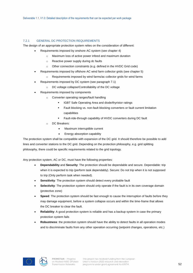
Deliverable 1.1, V1.0: Detailed description of the requirements that can be expected per work package
52
7.2.1 GENERAL DC PROTECTION REQUIREMENTS
The design of an appropriate protection system relies on the consideration of different:
Requirements imposed by onshore AC system (see chapter 4)
o Maximum loss of active power infeed and maximum duration
o Reactive power supply during dc faults
o Other connection constraints (e.g. defined in the HVDC Grid code)
Requirements imposed by offshore AC wind farm collector grids (see chapter 5)
o Requirements imposed by wind farms/ac collector grids for wind farms
Requirements imposed by DC system (see paragraph 7.1)
o DC voltage collapse/Controllability of the DC voltage
Requirements imposed by components
o Converter operating ranges/fault handling
IGBT Safe Operating Area and diode/thyristor ratings
Fault blocking vs. non-fault blocking converters or fault current limitation
capabilities
Fault-ride-through capability of HVDC converters during DC fault
o DC Breakers:
Maximum interruptible current
Energy absorption capability
The protection system shall be compatible with expansion of the DC grid. It should therefore be possible to add
lines and converter stations to the DC grid. Depending on the protection philosophy, e.g. grid splitting
philosophy, there could be specific requirements related to the grid topology.
Any protection system, AC or DC, must have the following properties:
Dependability and Security: The protection should be dependable and secure. Dependable: trip
when it is expected to trip (perform task dependably). Secure: Do not trip when it is not supposed
to trip (Only perform task when needed).
Sensitivity: The protection system should detect every probable fault
Selectivity: The protection system should only operate if the fault is in its own coverage domain
(protective zone)
Speed: The protection system should be fast enough to cause the interruption of faults before they
may damage equipment, before a system collapse occurs and within the time-frame that allows
the DC breaker to clear the fault.
Reliability: A good protection system is reliable and has a backup system in case the primary
protection system fails
Robustness: the protection system should have the ability to detect faults in all operation modes
and to discriminate faults from any other operation occurring (setpoint changes, operations, etc.)
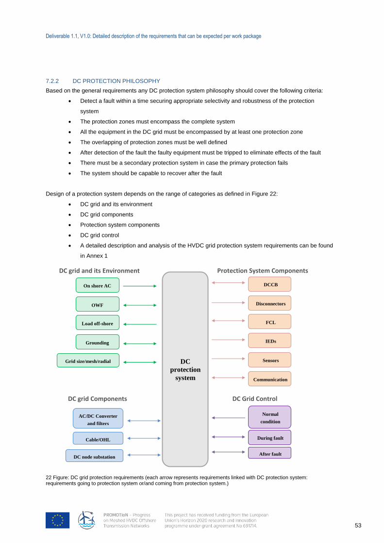
Deliverable 1.1, V1.0: Detailed description of the requirements that can be expected per work package
53
7.2.2 DC PROTECTION PHILOSOPHY
Based on the general requirements any DC protection system philosophy should cover the following criteria:
Detect a fault within a time securing appropriate selectivity and robustness of the protection
system
The protection zones must encompass the complete system
All the equipment in the DC grid must be encompassed by at least one protection zone
The overlapping of protection zones must be well defined
After detection of the fault the faulty equipment must be tripped to eliminate effects of the fault
There must be a secondary protection system in case the primary protection fails
The system should be capable to recover after the fault
Design of a protection system depends on the range of categories as defined in Figure 22:
DC grid and its environment
DC grid components
Protection system components
DC grid control
A detailed description and analysis of the HVDC grid protection system requirements can be found
in Annex 1
DC
protection
system
On shore AC
OWF
Load off-shore
AC/DC Converter
and filters
Cable/OHL
Grounding
Grid size/mesh/radial
DC node substation
DCCB
FCL
IEDs
Sensors
Communication
Normal
condition
During fault
After fault
DC grid and its Environment
DC grid Components DC Grid Control
Protection System Components
Disconnectors
22 Figure: DC grid protection requirements (each arrow represents requirements linked with DC protection system: requirements going to protection system or/and coming from protection system.)
Deliverable 1.1, V1.0: Detailed description of the requirements that can be expected per work package
54
7.2.3 DC GRID CONTROL DURING DC FAULT
DC Grid Control includes the individual converter control and coordination among the converters. The HVDC
grid will be affected in all protection strategies. Depending on the characteristics of the fault clearing device,
fault currents can be interrupted without significant delay or after some time. After this time, DC grid control shall
restore a new load flow. Therefore, DC grid control and DC grid protection are linked.
7.2.3.1 DC GRID CONTROL IN NORMAL CONDITION
The protection system has to be robust (to avoid unnecessary tripping) against current and voltage transients in
normal operations, like changes of the power flow set point, line opening and line closing.
7.2.3.2 DC GRID CONTROL DURING FAULT
Depending on the protection philosophy, the converter can be required to control the DC voltage and fault
current. Additionally converters may be required to have an ability to provide reactive power support the AC
system as previously described in Chapter 4.
7.2.3.3 DC GRID CONTROL AFTER FAULT
After the fault clearing process a new power flow has to be restored in the DC grid. According to the DC grid
control a nd converter control, this power restoration process will take a certain duration.
Deliverable 1.1, V1.0: Detailed description of the requirements that can be expected per work package
55
7.3 STEADY STATE OPERATION
7.3.1 SCADA SYSTEM REQUIREMENTS
The SCADA (Supervisory Control And Data Acquisition) system is essential for the remote control and
monitoring of DC grids. Two types of SCADA systems will be part of the DC grid:
Wind farm SCADA
DC grid operator SCADA
1. Each offshore wind farm is controlled by its own SCADA. This system monitors and controls the MV
switchgear of the collector substation and if required the array cable switchgear at the turbine. This
SCADA system must pass both hardwire and communication signals to the DC grid operator SCADA.
It is essential that both SCADA systems are independent and do not share common equipment so that
clear interface boundaries can be established.
2. A gateway must allow data to be transferred to the DC grid operator control centre. This link must
provide access to all monitored values and allow all commands and setpoints to be controlled
remotely.
3. The SCADA systems must be designed so that the operation, maintenance and any potential updates
to a SCADA node can be done independently without any undesired effects in the availability and
information in the other SCADA nodes.
4. The control systems must be designed for high availability, such that the loss of any I/O card or
component has a minimal effect on the DC grid or wind farm operability or availability.
5. The SCADA systems must provide a local HMI (Human-Machine Interface) at the converter Stations
and the for the DC grid and for the wind farm SCADA. The SCADA functionality must be identical at all
SCADA nodes offshore, onshore and remotely connected locations. A robust system must be put in
place to determine the point of control at any point in time.
6. The SCADA system must be designed so that the failure of a single communication route does not
cause a SCADA system to fail
7.3.2 COMMUNICATION SYSTEM REQUIREMENTS
The communications scheme must be fully redundant.
All the systems should comply with local and national regulations.
Deliverable 1.1, V1.0: Detailed description of the requirements that can be expected per work package
56
7.4 DISCUSSION OF REQUIREMENTS
The following should be considered in the next discussions in PROMOTioN project with regard to the
requirements set out in this section:
The requirements are not based on any existing grid code and significant changes and additions
may occur during progress of PROMOTioN project.
Some requirements are subject to technology-dependency, as well as dependency on what
connects at the HVDC Terminal’s AC side. This is to be accounted for in the quantification
process. An iterative process could be needed in order to establish optimal requirements from
technical and economical prospective.
Requirements for DC grid energy dissipation in case of grid disconnection should be defined; DC
chopper of any other solution could be investigated.
DC/DC converters and power flow controllers are not yet considered due to lack of available
technology in short-term horizon. Although, in the long-term planning these technologies could
become available and should not be totally neglected.
The duration of the restoration of the power flow after a fault impacts the protection system
philosophy. Otherwise the protection philosophy can impose requirements on the restoration
duration.
The following should be considered in the next iterations in PROMOTioN project with regard to the requirements
set out in this section:
The requirements are not based on any existing code and significant changes and additions may
occur.
The above changes and additions will have to be driven mainly by the work of WPs 2, 3, 4 and 5.
Some requirements are subject to technology-dependency, as well as dependency on what
connects at the HVDC Terminal’s AC side. This is to be accounted for in the quantification
process.
Deliverable 1.1, V1.0: Detailed description of the requirements that can be expected per work package
57
8 NON-FUNCTIONAL REQUIREMENTS
The non-functional requirements are typically imposed by stakeholders, with different interests, and they are
essential for the feasibility of cross-border meshed offshore grids. These requirements are just as critical as the
functional ones, as they ensure the economic viability and political (and social) feasibility of the entire meshed
offshore grid (MOG). The MOG should meet these requirements, in addition to the functional ones, in order to
achieve a highly developed cross-border offshore electricity grid interconnection and improve energy security.
The present chapter contains a list of the main non-functional requirements, which are needed as 'first-step' or
primary requirements. These are essential requirements for the initial development of any MOG. This means
that secondary requirements, like e.g. common Health and Safety/Environment (HSE) standards and technical
regulatory aspects, as embedded in technical grid codes, are not listed here. These more technical (regulatory)
aspects are addressed in the preceding chapters concerning the functional requirements. However, this list may
be subject to change prior to final publication in WP7. WP7 will focus on the fundamental requirements in terms
of investment regulatory aspects of the North Sea grid (planning and design, construction and the most
important operational market aspects).
The following aspects/requirements are closely intertwined and interdependent.
8.1 ENERGY POLICY ASPECTS
In principle, a MOG should be feasible and desirable from an EU policy perspective. Due to substantial
differences in national legislation, social acceptance and political commitment from policy makers in the EU is
needed in order to accept a uniform set of rules and agreements for the regulation of a meshed offshore grid.
Realisation and operation of the meshed offshore grid
Contribution to the internal energy market and other EU objectives like security of supply, as well as the EU’s
environmental and climate objectives
8.2 LEGAL AND REGULATORY ASPECTS
The current EU framework does not provide specific rules for the development of a MOG. This leads to serious
uncertainties regarding the legal classification of offshore assets in relation to the applicable regulatory
framework. Parties who are allowed to invest in (and operate) the grid infrastructure must be legally appointed.
Investing parties have to know what the rules of the game are in terms of financial support schemes and other
legal requirements which might affect their investment decision. Liability of the grid operators vis-à-vis the wind
farm developers is also a crucial legal aspect, e.g. compensation schemes in case of delays, grid outages, or
other technical constraints on the MOG. The current lack of clarity and absence of legal rules is a major
obstacle in the development of any MOG. A clear legal framework is required, implemented in European law or

Deliverable 1.1, V1.0: Detailed description of the requirements that can be expected per work package
58
bilateral/multilateral agreements among Member States linked to a MOG, which will provide sufficient legal
certainty for offshore infrastructure wind farm investors. To this end, the following conditions should be fulfilled,
as minimum legal and regulatory requirements:
Legal definitions for integrated offshore transmission infrastructures
Ownership of offshore assets, and the interfaces between different asset owners
Responsibilities and roles of involved parties (e.g. grid connection responsible parties, energy
program/balance responsible parties or ''BRPs'')
Priority grid access for offshore wind farms
Convergence and compatibility of national renewable support schemes for offshore wind farms
Coordinated cross-border/EU planning and design of the MOG (e.g. based on minimum standards
for an entire sea basin)
Rules on liability and compensation of different stakeholders (grid operators, wind developers)
Rules on the interaction with the national onshore transmission systems regulations and
requirements
Transmission tariff design and generation tariff design
Implementation/ codification of a designated North Sea/ Baltic Sea grid regulatory framework
Permitting and planning requirements
Common standards, e.g. environmental and HSE
Deliverable 1.1, V1.0: Detailed description of the requirements that can be expected per work package
59
8.3 FINANCIAL-ECONOMIC ASPECTS
Highly relevant for the political acceptance and active participation in the MOG is that the costs are fairly
distributed between beneficiaries, taking into account the welfare distributions of the MOG. This means that a
proper methodology is needed to rank the benefits and the costs of offshore electricity grid investments. Equally
important is that parties are incentivised to invest in the MOG, and in the associated offshore wind farm/RES
assets. For example, this means that the revenues and the financial reward for these investments should be
balanced against the risks incurred by investing parties. Given the investment challenge of the MOG and
offshore RES generation units, instruments and solutions are needed to address debt and equity financing
constraints. To this end, ownership models and (joint) investor participation such as public-private partnerships
can play an important role. Therefore, a financial-economic regulatory framework for integrated offshore
transmission investments is required. In order to meet this requirement the following conditions should be
fulfilled:
Evaluation of cost and benefits of the investments
Total cost overview
Fair cost allocation method across EU Member States/beneficiaries, taking into account welfare
distributions
Cost recovery/revenue schemes for transmission/OWF investments
(Financial and non-financial) investment incentives
Evaluation of investment and operational risks in relation to allowed returns
Instruments to attract debt and equity capital (at reasonable cost)
(Joint) investor participation (e.g. public-private partnerships) and funding mechanisms
8.4 MARKET ASPECTS
The most important ''first step'' market aspect when it comes to a MOG is the market framework for the
interconnection usage. This is closely related to the production of wind power at the offshore wind farms. In
case the offshore wind farms have prioritized access to the grid, it needs to be determined how the remaining
capacity will be given to the cross-border trade on the interconnectors. Furthermore, grid operators are required
by the regulator to purchase ancillary services for transport and system balancing. Given the intermittent nature
of wind infeed, contracts with suppliers of ancillary services, connected to the onshore transmission
infrastructures, might be needed. Important market aspects are:
Rules on generation capacity and interconnection usage (capacity allocation)
Rules on ancillary services
Trading and auction rules
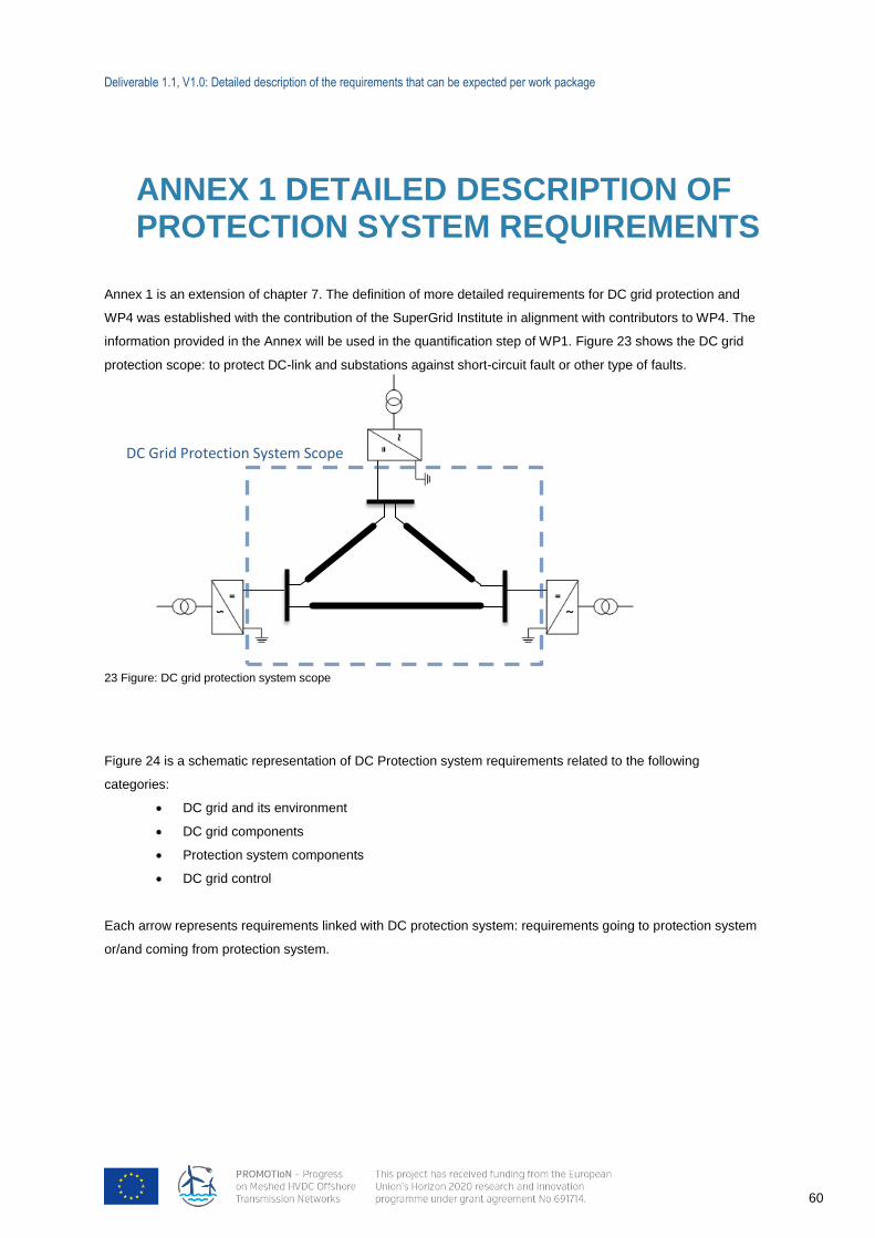
Deliverable 1.1, V1.0: Detailed description of the requirements that can be expected per work package
60
ANNEX 1 DETAILED DESCRIPTION OF PROTECTION SYSTEM REQUIREMENTS
Annex 1 is an extension of chapter 7. The definition of more detailed requirements for DC grid protection and
WP4 was established with the contribution of the SuperGrid Institute in alignment with contributors to WP4. The
information provided in the Annex will be used in the quantification step of WP1. Figure 23 shows the DC grid
protection scope: to protect DC-link and substations against short-circuit fault or other type of faults.
23 Figure: DC grid protection system scope
Figure 24 is a schematic representation of DC Protection system requirements related to the following
categories:
DC grid and its environment
DC grid components
Protection system components
DC grid control
Each arrow represents requirements linked with DC protection system: requirements going to protection system
or/and coming from protection system.
DC Grid Protection System Scope
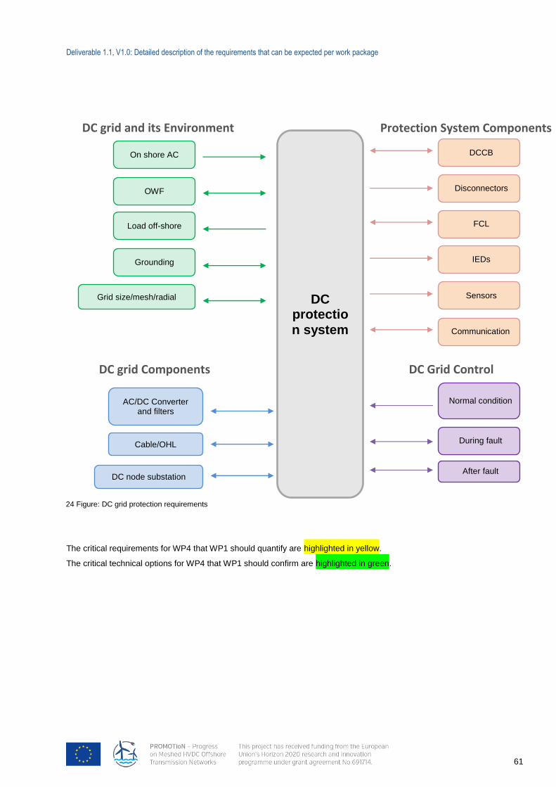
Deliverable 1.1, V1.0: Detailed description of the requirements that can be expected per work package
61
The critical requirements for WP4 that WP1 should quantify are highlighted in yellow.
The critical technical options for WP4 that WP1 should confirm are highlighted in green.
DC protectio
n system
On shore AC
OWF
Load off-shore
AC/DC Converter and filters
Cable/OHL
Grounding
Grid size/mesh/radial
DC node substation
DCCB
FCL
IEDs
Sensors
Communication
Normal condition
During fault
After fault
DC grid and its Environment
DC grid Components DC Grid Control
Protection System Components
Disconnectors
24 Figure: DC grid protection requirements
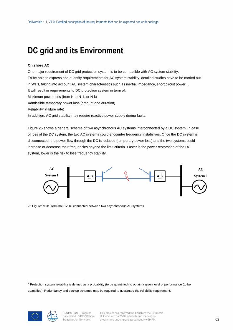
Deliverable 1.1, V1.0: Detailed description of the requirements that can be expected per work package
62
DC grid and its Environment On shore AC
One major requirement of DC grid protection system is to be compatible with AC system stability.
To be able to express and quantify requirements for AC system stability, detailed studies have to be carried out
in WP1, taking into account AC system characteristics such as inertia, impedance, short circuit power…
It will result in requirements to DC protection system in term of:
Maximum power loss (from N to N-1, or N-k)
Admissible temporary power loss (amount and duration)
Reliability9 (failure rate)
In addition, AC grid stability may require reactive power supply during faults.
Figure 25 shows a general scheme of two asynchronous AC systems interconnected by a DC system. In case
of loss of the DC system, the two AC systems could encounter frequency instabilities. Once the DC system is
disconnected, the power flow through the DC is reduced (temporary power loss) and the two systems could
increase or decrease their frequencies beyond the limit criteria. Faster is the power restoration of the DC
system, lower is the risk to lose frequency stability.
25 Figure: Multi Terminal HVDC connected between two asynchronous AC systems
9 Protection system reliability is defined as a probability (to be quantified) to obtain a given level of performance (to be
quantified). Redundancy and backup schemes may be required to guarantee the reliability requirement.
AC
System 1
AC
System 2
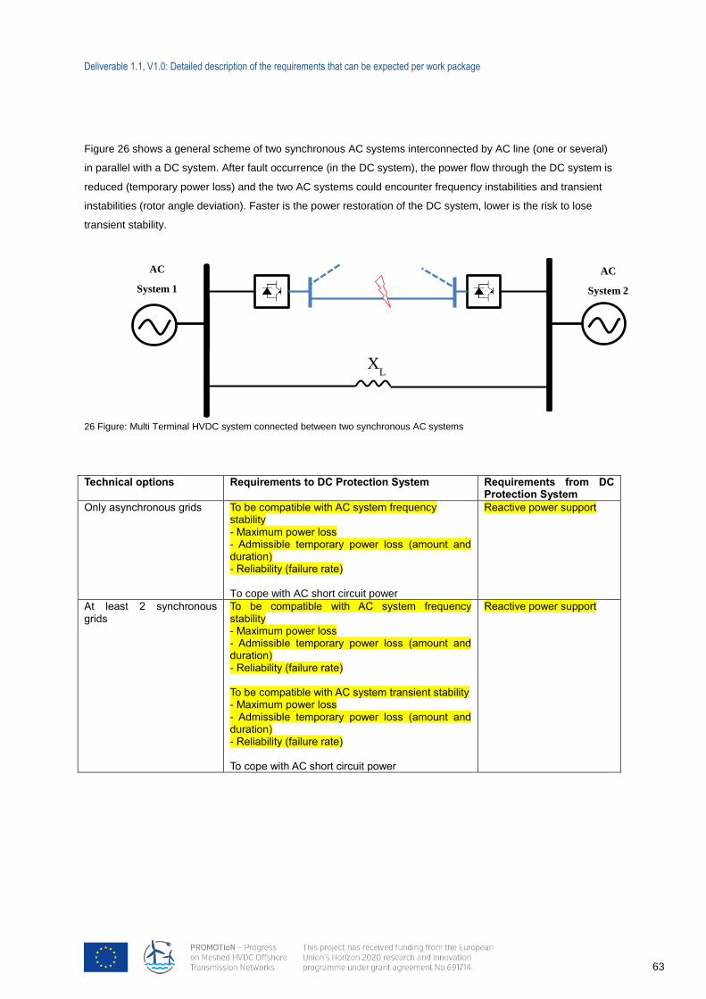
Deliverable 1.1, V1.0: Detailed description of the requirements that can be expected per work package
63
Figure 26 shows a general scheme of two synchronous AC systems interconnected by AC line (one or several)
in parallel with a DC system. After fault occurrence (in the DC system), the power flow through the DC system is
reduced (temporary power loss) and the two AC systems could encounter frequency instabilities and transient
instabilities (rotor angle deviation). Faster is the power restoration of the DC system, lower is the risk to lose
transient stability.
26 Figure: Multi Terminal HVDC system connected between two synchronous AC systems
Technical options Requirements to DC Protection System Requirements from DC Protection System
Only asynchronous grids
To be compatible with AC system frequency stability - Maximum power loss - Admissible temporary power loss (amount and duration) - Reliability (failure rate) To cope with AC short circuit power
Reactive power support
At least 2 synchronous grids
To be compatible with AC system frequency stability - Maximum power loss - Admissible temporary power loss (amount and duration) - Reliability (failure rate) To be compatible with AC system transient stability - Maximum power loss - Admissible temporary power loss (amount and duration) - Reliability (failure rate) To cope with AC short circuit power
Reactive power support
XL
AC
System 1
AC
System 2
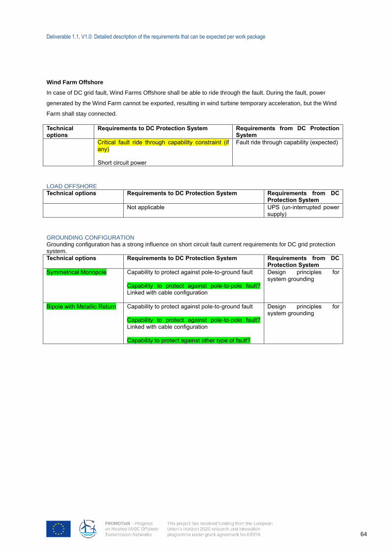
Deliverable 1.1, V1.0: Detailed description of the requirements that can be expected per work package
64
Wind Farm Offshore
In case of DC grid fault, Wind Farms Offshore shall be able to ride through the fault. During the fault, power
generated by the Wind Farm cannot be exported, resulting in wind turbine temporary acceleration, but the Wind
Farm shall stay connected.
Technical options
Requirements to DC Protection System Requirements from DC Protection System
Critical fault ride through capability constraint (if any) Short circuit power
Fault ride through capability (expected)
LOAD OFFSHORE
Technical options Requirements to DC Protection System Requirements from DC Protection System
Not applicable UPS (un-interrupted power supply)
GROUNDING CONFIGURATION Grounding configuration has a strong influence on short circuit fault current requirements for DC grid protection system.
Technical options Requirements to DC Protection System Requirements from DC Protection System
Symmetrical Monopole Capability to protect against pole-to-ground fault Capability to protect against pole-to-pole fault? Linked with cable configuration
Design principles for system grounding
Bipole with Metallic Return Capability to protect against pole-to-ground fault Capability to protect against pole-to-pole fault? Linked with cable configuration Capability to protect against other type of fault?
Design principles for system grounding
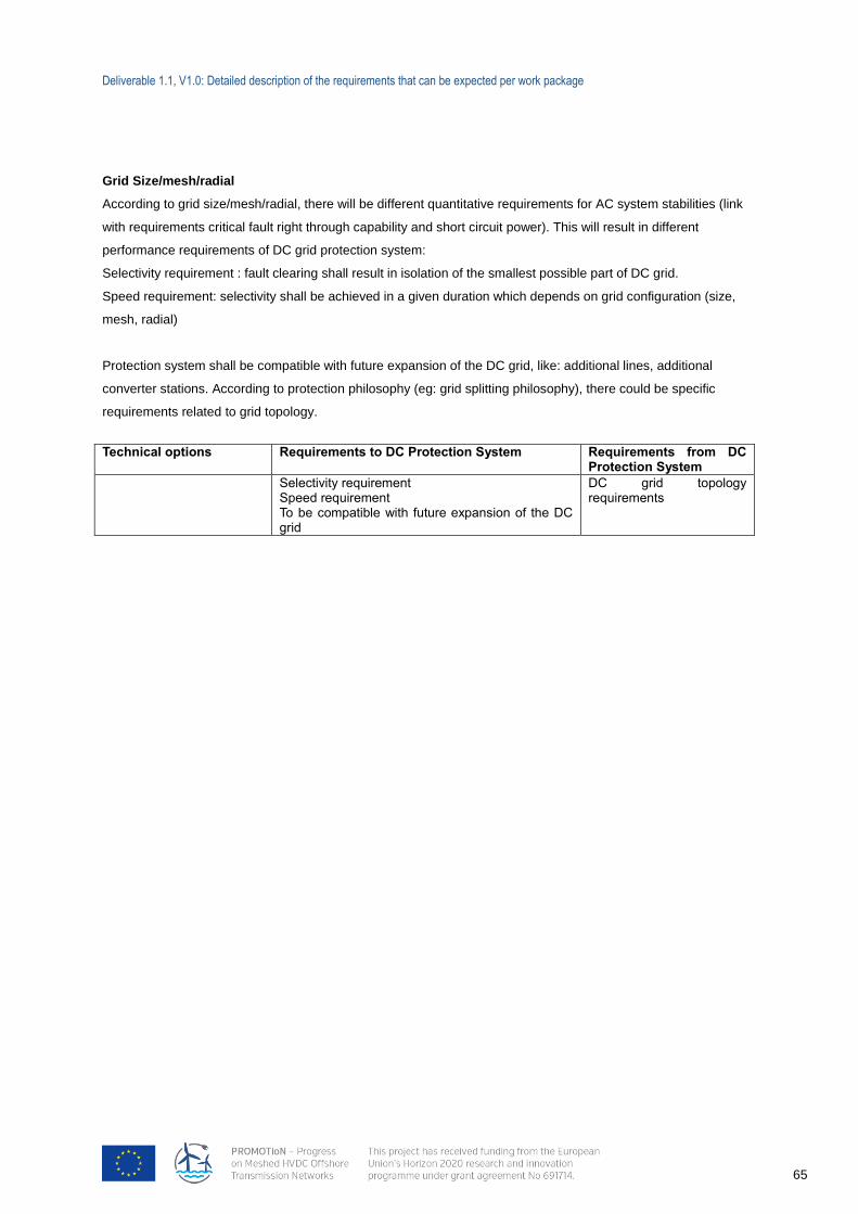
Deliverable 1.1, V1.0: Detailed description of the requirements that can be expected per work package
65
Grid Size/mesh/radial
According to grid size/mesh/radial, there will be different quantitative requirements for AC system stabilities (link
with requirements critical fault right through capability and short circuit power). This will result in different
performance requirements of DC grid protection system:
Selectivity requirement : fault clearing shall result in isolation of the smallest possible part of DC grid.
Speed requirement: selectivity shall be achieved in a given duration which depends on grid configuration (size,
mesh, radial)
Protection system shall be compatible with future expansion of the DC grid, like: additional lines, additional
converter stations. According to protection philosophy (eg: grid splitting philosophy), there could be specific
requirements related to grid topology.
Technical options Requirements to DC Protection System Requirements from DC Protection System
Selectivity requirement Speed requirement To be compatible with future expansion of the DC grid
DC grid topology requirements
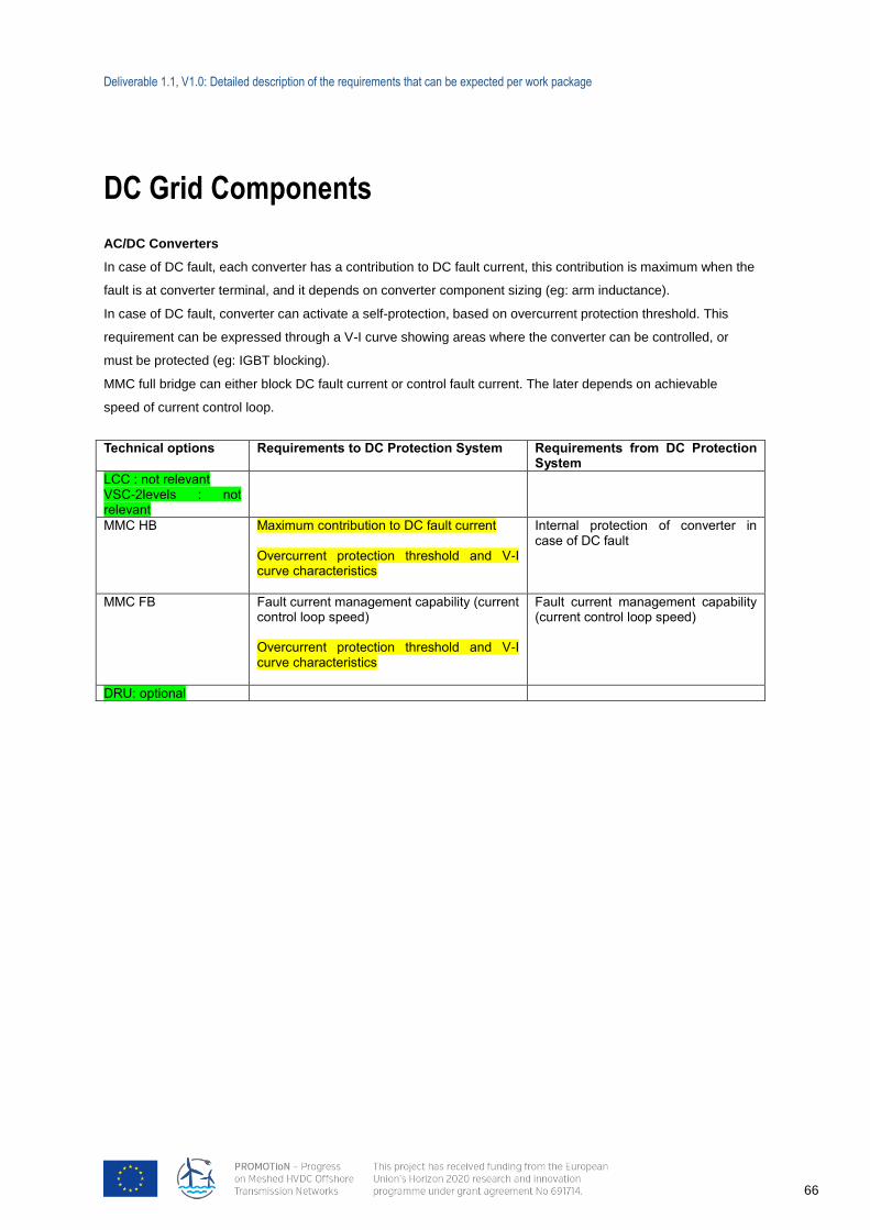
Deliverable 1.1, V1.0: Detailed description of the requirements that can be expected per work package
66
DC Grid Components
AC/DC Converters
In case of DC fault, each converter has a contribution to DC fault current, this contribution is maximum when the
fault is at converter terminal, and it depends on converter component sizing (eg: arm inductance).
In case of DC fault, converter can activate a self-protection, based on overcurrent protection threshold. This
requirement can be expressed through a V-I curve showing areas where the converter can be controlled, or
must be protected (eg: IGBT blocking).
MMC full bridge can either block DC fault current or control fault current. The later depends on achievable
speed of current control loop.
Technical options Requirements to DC Protection System Requirements from DC Protection System
LCC : not relevant VSC-2levels : not relevant
MMC HB Maximum contribution to DC fault current Overcurrent protection threshold and V-I curve characteristics
Internal protection of converter in case of DC fault
MMC FB Fault current management capability (current control loop speed) Overcurrent protection threshold and V-I curve characteristics
Fault current management capability (current control loop speed)
DRU: optional
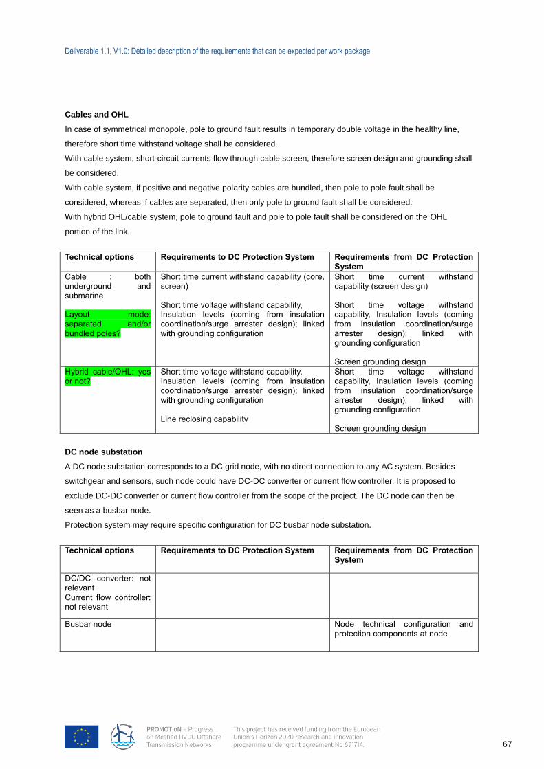
Deliverable 1.1, V1.0: Detailed description of the requirements that can be expected per work package
67
Cables and OHL
In case of symmetrical monopole, pole to ground fault results in temporary double voltage in the healthy line,
therefore short time withstand voltage shall be considered.
With cable system, short-circuit currents flow through cable screen, therefore screen design and grounding shall
be considered.
With cable system, if positive and negative polarity cables are bundled, then pole to pole fault shall be
considered, whereas if cables are separated, then only pole to ground fault shall be considered.
With hybrid OHL/cable system, pole to ground fault and pole to pole fault shall be considered on the OHL
portion of the link.
Technical options Requirements to DC Protection System Requirements from DC Protection System
Cable : both underground and submarine Layout mode: separated and/or bundled poles?
Short time current withstand capability (core, screen) Short time voltage withstand capability, Insulation levels (coming from insulation coordination/surge arrester design); linked with grounding configuration
Short time current withstand capability (screen design) Short time voltage withstand capability, Insulation levels (coming from insulation coordination/surge arrester design); linked with grounding configuration Screen grounding design
Hybrid cable/OHL: yes or not?
Short time voltage withstand capability, Insulation levels (coming from insulation coordination/surge arrester design); linked with grounding configuration Line reclosing capability
Short time voltage withstand capability, Insulation levels (coming from insulation coordination/surge arrester design); linked with grounding configuration Screen grounding design
DC node substation
A DC node substation corresponds to a DC grid node, with no direct connection to any AC system. Besides
switchgear and sensors, such node could have DC-DC converter or current flow controller. It is proposed to
exclude DC-DC converter or current flow controller from the scope of the project. The DC node can then be
seen as a busbar node.
Protection system may require specific configuration for DC busbar node substation.
Technical options Requirements to DC Protection System Requirements from DC Protection System
DC/DC converter: not relevant Current flow controller: not relevant
Busbar node Node technical configuration and protection components at node
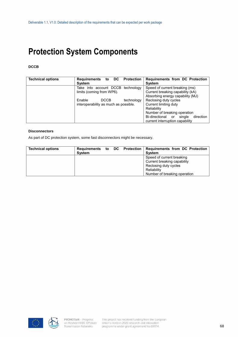
Deliverable 1.1, V1.0: Detailed description of the requirements that can be expected per work package
68
Protection System Components
DCCB
Technical options Requirements to DC Protection System
Requirements from DC Protection System
Take into account DCCB technology limits (coming from WP6). Enable DCCB technology interoperability as much as possible.
Speed of current breaking (ms) Current breaking capability (kA) Absorbing energy capability (MJ) Reclosing duty cycles Current limiting duty Reliability Number of breaking operation Bi-directional or single direction current interruption capability
Disconnectors
As part of DC protection system, some fast disconnectors might be necessary.
Technical options Requirements to DC Protection System
Requirements from DC Protection System
Speed of current breaking Current breaking capability Reclosing duty cycles Reliability Number of breaking operation
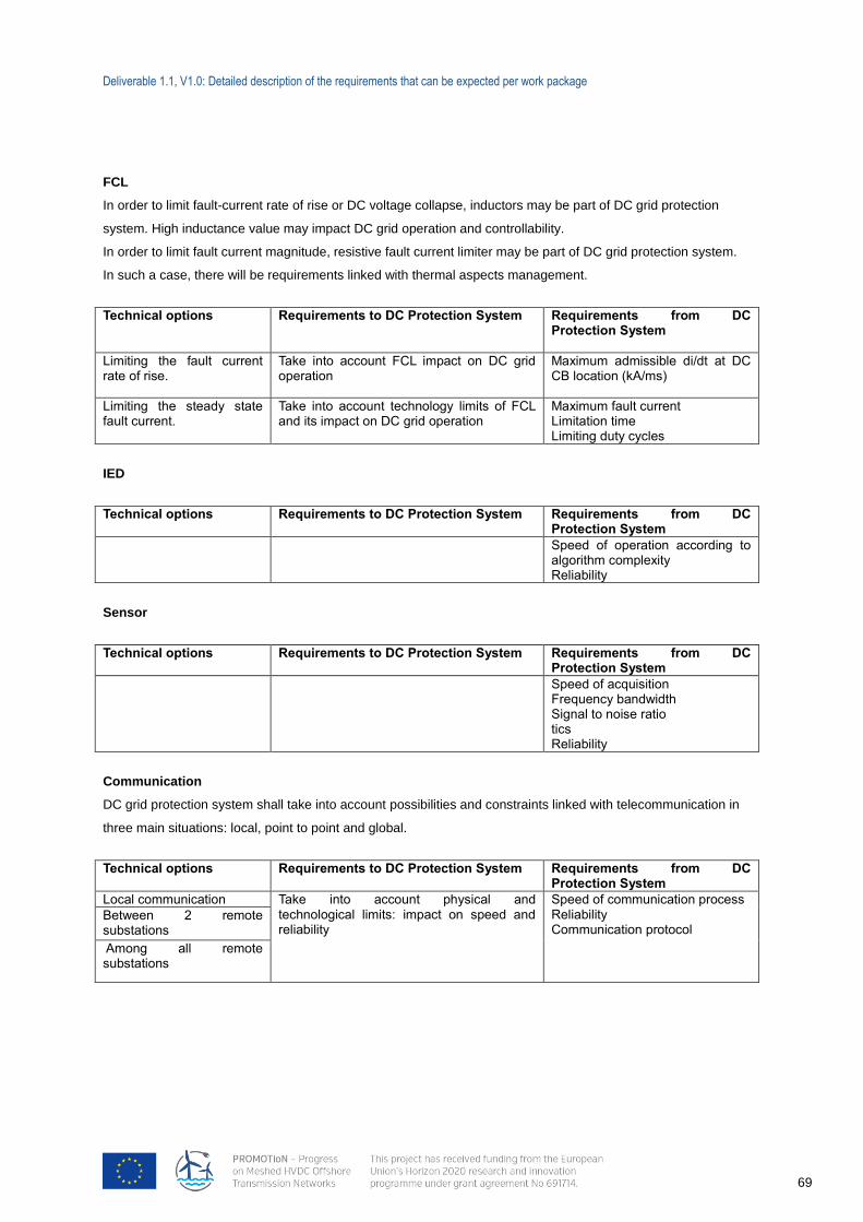
Deliverable 1.1, V1.0: Detailed description of the requirements that can be expected per work package
69
FCL
In order to limit fault-current rate of rise or DC voltage collapse, inductors may be part of DC grid protection
system. High inductance value may impact DC grid operation and controllability.
In order to limit fault current magnitude, resistive fault current limiter may be part of DC grid protection system.
In such a case, there will be requirements linked with thermal aspects management.
Technical options Requirements to DC Protection System Requirements from DC Protection System
Limiting the fault current rate of rise.
Take into account FCL impact on DC grid operation
Maximum admissible di/dt at DC CB location (kA/ms)
Limiting the steady state fault current.
Take into account technology limits of FCL and its impact on DC grid operation
Maximum fault current Limitation time Limiting duty cycles
IED
Technical options Requirements to DC Protection System Requirements from DC Protection System
Speed of operation according to algorithm complexity Reliability
Sensor
Technical options Requirements to DC Protection System Requirements from DC Protection System
Speed of acquisition Frequency bandwidth Signal to noise ratio tics Reliability
Communication
DC grid protection system shall take into account possibilities and constraints linked with telecommunication in
three main situations: local, point to point and global.
Technical options Requirements to DC Protection System Requirements from DC Protection System
Local communication Take into account physical and technological limits: impact on speed and reliability
Speed of communication process Reliability Communication protocol
Between 2 remote substations
Among all remote substations
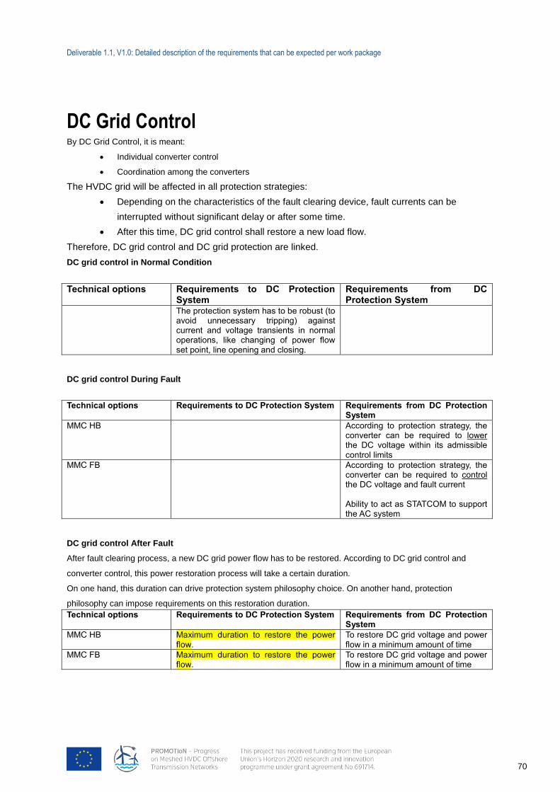
Deliverable 1.1, V1.0: Detailed description of the requirements that can be expected per work package
70
DC Grid Control By DC Grid Control, it is meant:
Individual converter control
Coordination among the converters
The HVDC grid will be affected in all protection strategies:
Depending on the characteristics of the fault clearing device, fault currents can be
interrupted without significant delay or after some time.
After this time, DC grid control shall restore a new load flow.
Therefore, DC grid control and DC grid protection are linked.
DC grid control in Normal Condition
Technical options Requirements to DC Protection System
Requirements from DC Protection System
The protection system has to be robust (to avoid unnecessary tripping) against current and voltage transients in normal operations, like changing of power flow set point, line opening and closing.
DC grid control During Fault
Technical options Requirements to DC Protection System Requirements from DC Protection System
MMC HB According to protection strategy, the converter can be required to lower the DC voltage within its admissible control limits
MMC FB According to protection strategy, the converter can be required to control the DC voltage and fault current Ability to act as STATCOM to support the AC system
DC grid control After Fault
After fault clearing process, a new DC grid power flow has to be restored. According to DC grid control and
converter control, this power restoration process will take a certain duration.
On one hand, this duration can drive protection system philosophy choice. On another hand, protection
philosophy can impose requirements on this restoration duration.
Technical options Requirements to DC Protection System Requirements from DC Protection System
MMC HB Maximum duration to restore the power flow.
To restore DC grid voltage and power flow in a minimum amount of time
MMC FB Maximum duration to restore the power flow.
To restore DC grid voltage and power flow in a minimum amount of time
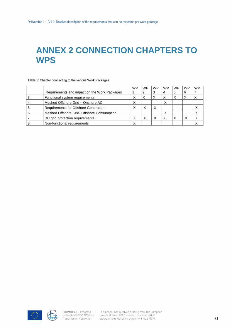
Deliverable 1.1, V1.0: Detailed description of the requirements that can be expected per work package
71
ANNEX 2 CONNECTION CHAPTERS TO WPS
Table 5: Chapter connecting to the various Work Packages
Requirements and impact on the Work Packages WP1
WP2
WP3
WP4
WP5
WP6
WP7
3. Functional system requirements X X X X X X X
4. Meshed Offshore Grid – Onshore AC X X
5. Requirements for Offshore Generation X X X X
6. Meshed Offshore Grid- Offshore Consumption X X
7. DC grid protection requirements . X X X X X X X
8. Non-functional requirements X X
Deliverable 1.1, V1.0: Detailed description of the requirements that can be expected per work package
72
ANNEX 3 HVDC GRID CODE
Introduction
This report is part of the WP1 of the PROMOTION project whose topic is “requirements for meshed offshore
grids”. Within this work package, the work conducted here is a part of the subtask 1.1 whose overall objective is
to define requirements, reference scenarios and fundamental topologies for HVDC systems. This a crucial step
since harmonized rules and requirements for HVDC systems would allow for transparent grid connection
procedures and processes for HVDC systems leader to faster deployment of this technology and ultimately
facilitating Union-wide trade in electricity, ensuring system security, facilitating the integration of renewable
electricity resources and offshore wind in particular and increasing competition on the electricity markets. To this
end, the European commission has drafted a specific network code dedicated to HVDC systems and current-
connected power park modules. This report focuses on analysing current grid codes and regulations applicable
to HVDC systems in Europe. The outcome and objective of the document is to synthetize the different
requirements that HVDC systems must comply with in the EU. This entails both functionalities that the systems
should be able to accomplish as well as constraints within which the HVDC systems are required to operate for
smooth integration into the hosting AC systems. More specifically, this report extracts the most relevant
technical requirements from the European Commission network code for HVDC systems: “Establishing a
network code on requirements for grid connection of high voltage direct current systems and direct-current
connected power park modules” (version of 11/09/2015).
Structure of the network code
The document is structured around different so-called “titles”, each further decomposed into chapters and
ultimately network code articles. The most relevant content and requirements from the different titles of the
document have been extracted and synthetized in this report and are presented in the following sections.
Deliverable 1.1, V1.0: Detailed description of the requirements that can be expected per work package
73
Title 1: General provisions
This section of the network code describes general information that is useful for the rest of the titles of the
document, such as subject matter, definitions, scope of application, regulatory aspects, stakeholder involvement
and interactions.
This part of the document starts by defining several classical HVDC system components and terminologies for
clarity purposes with respect to the remainder of the network code document. The scope of application of the
network code is then explicitly described. The applicability of specific articles within the network code which
entail particular exemptions is detailed.
It is worth to highlight the different HVDC systems and associated definitions that are studied and defined in the
network code:
‘HVDC system' means an electrical power system which transfers energy in the form of high-
voltage direct current between two or more alternating current (AC) buses and comprises at least
two HVDC converter stations with DC transmission lines or cables between the HVDC converter
stations;
‘DC-connected power park module' means a power park module that is connected via one or more
HVDC interface points to one or more HVDC systems;
‘embedded HVDC system' means an HVDC system connected within a control area that is not
installed for the purpose of connecting a DC-connected power park module at the time of
installation, nor installed for the purpose of connecting a demand facility;
‘HVDC converter station' means part of an HVDC system which consists of one or more HVDC
converter units installed in a single location together with buildings, reactors, filters, reactive power
devices, control, monitoring, protective, measuring and auxiliary equipment.
The requirements of the network code apply to all the above HVDC systems but sometimes the requirements
are differentiated according to the specific nature of the HVDC system.
The general provisions specifiy that the regulation code does not apply to systems whose voltage is below
110kV unless a cross-border impact is demonstrated by the relevant TSO. It equally does not apply to HVDC
systems which are connected to parts of transmission or distribution systems of electrical islands within
Continental Europe.
The network code applies only to new HVDC systems and not to existing ones, apart for some specific cases
which are described in detail within the title 1. Most notably, the application of part or full of this Regulation to
existing HVDC systems and/or DC-connected power park modules may be enforced should extreme system
changes have occurred within the system (i.e. penetration of renewables, smart grids…), following proposal
from the relevant TSO and public consultation. The decision for retroactive application then results from a cost-
benefit analysis and stakeholder involvement through public consultations.
The costs and expenses borne by system operators following the obligations laid down in the network code are
to be assessed by national regulatory authorities and recovered through network tariffs or other appropriate
mechanisms
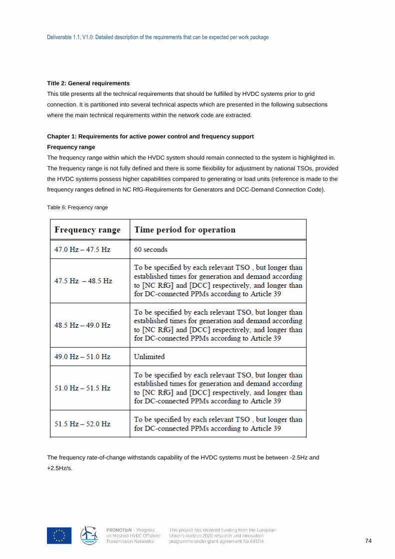
Deliverable 1.1, V1.0: Detailed description of the requirements that can be expected per work package
74
Title 2: General requirements
This title presents all the technical requirements that should be fulfilled by HVDC systems prior to grid
connection. It is partitioned into several technical aspects which are presented in the following subsections
where the main technical requirements within the network code are extracted.
Chapter 1: Requirements for active power control and frequency support
Frequency range
The frequency range within which the HVDC system should remain connected to the system is highlighted in.
The frequency range is not fully defined and there is some flexibility for adjustment by national TSOs, provided
the HVDC systems possess higher capabilities compared to generating or load units (reference is made to the
frequency ranges defined in NC RfG-Requirements for Generators and DCC-Demand Connection Code).
Table 6: Frequency range
The frequency rate-of-change withstands capability of the HVDC systems must be between -2.5Hz and
+2.5Hz/s.

Deliverable 1.1, V1.0: Detailed description of the requirements that can be expected per work package
75
Controllability
Several articles within the network code address the controllability of the HVDC systems. It is stated that HVDC
systems should be capable of controlling its active power injection up to its maximum power in each direction,
following an instruction received from the TSO. The TSO may specify:
A maximum and minimum step size for adjusting the transmitted active power;
A minimum HVDC power injection below which active power transmission capability is not requested;
The maximal allowed delay between receipt of the TSO request and start of the active power level
adjustment;
Adjustment of the ramping rate;
The control functions of an HVDC system shall be capable of taking automatic remedial actions
such as stopping the ramping and blocking FSM (Frequency Sensitive Mode), LFSM-O, LFSM-
U… The triggering and blocking criteria shall be specified by the relevant TSO;
Synthetic inertia shall be a present functionality of HVDC systems and shall be activated
depending of the needs of the system, as identified by the relevant TSO;
Fast power reversal (not more than 2s) shall be possible;
Maximum loss of active power
An HVDC system shall be configured in such a way that its loss of active power injection in a synchronous area
shall be limited to a value specified by the relevant TSOs for their respective load frequency control area, based
on the HVDC system's impact on the power system.
Where an HVDC system connects two or more control areas, the relevant TSOs shall consult each other in
order to set a coordinated value of the maximum loss of active power injection as referred to in paragraph 1,
taking into account common mode failures.
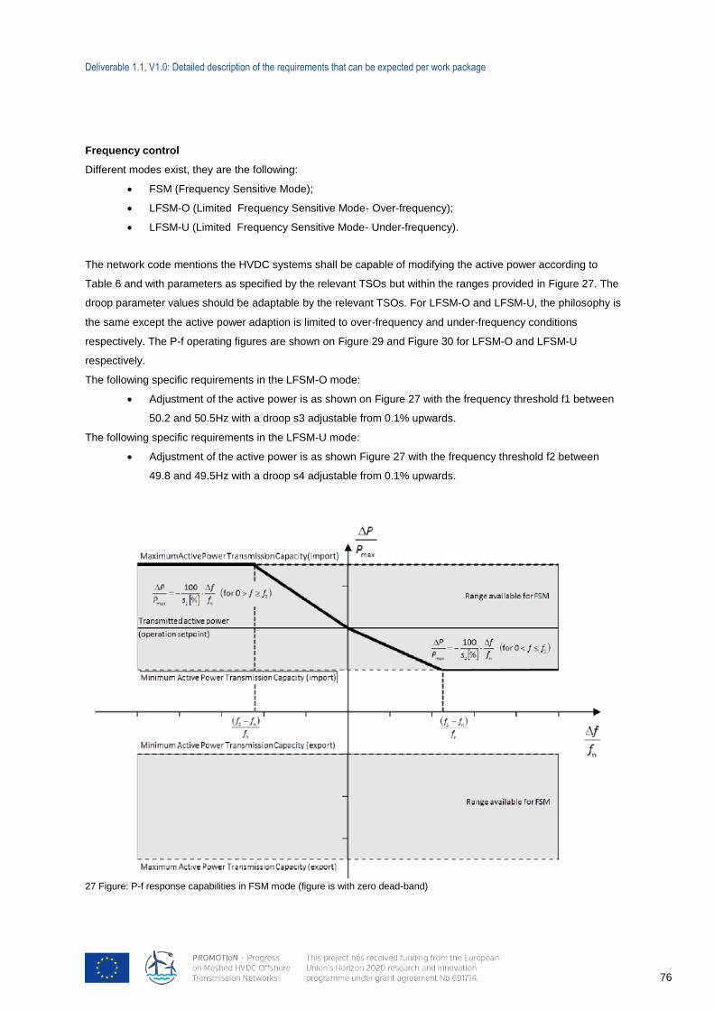
Deliverable 1.1, V1.0: Detailed description of the requirements that can be expected per work package
76
Frequency control
Different modes exist, they are the following:
FSM (Frequency Sensitive Mode);
LFSM-O (Limited Frequency Sensitive Mode- Over-frequency);
LFSM-U (Limited Frequency Sensitive Mode- Under-frequency).
The network code mentions the HVDC systems shall be capable of modifying the active power according to
Table 6 and with parameters as specified by the relevant TSOs but within the ranges provided in Figure 27. The
droop parameter values should be adaptable by the relevant TSOs. For LFSM-O and LFSM-U, the philosophy is
the same except the active power adaption is limited to over-frequency and under-frequency conditions
respectively. The P-f operating figures are shown on Figure 29 and Figure 30 for LFSM-O and LFSM-U
respectively.
The following specific requirements in the LFSM-O mode:
Adjustment of the active power is as shown on Figure 27 with the frequency threshold f1 between
50.2 and 50.5Hz with a droop s3 adjustable from 0.1% upwards.
The following specific requirements in the LFSM-U mode:
Adjustment of the active power is as shown Figure 27 with the frequency threshold f2 between
49.8 and 49.5Hz with a droop s4 adjustable from 0.1% upwards.
27 Figure: P-f response capabilities in FSM mode (figure is with zero dead-band)
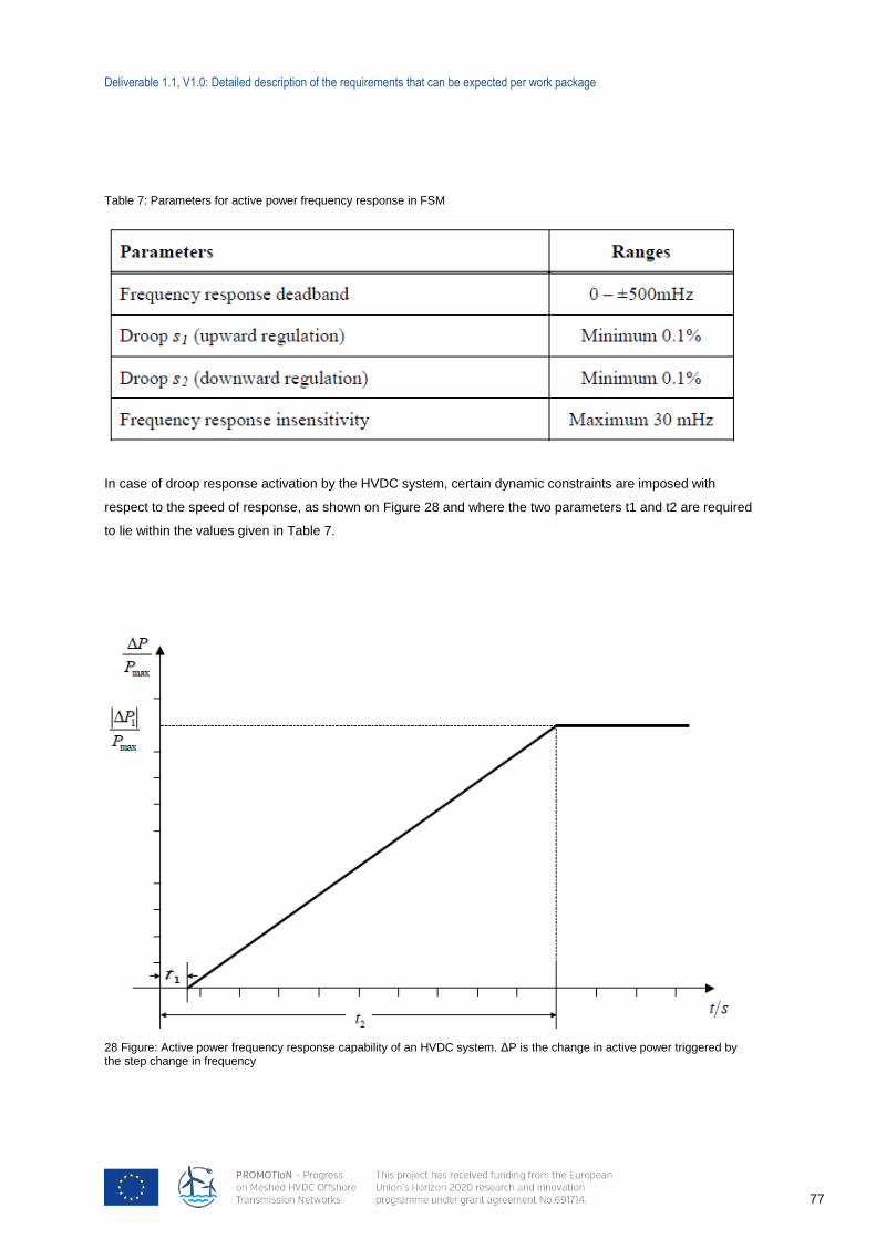
Deliverable 1.1, V1.0: Detailed description of the requirements that can be expected per work package
77
Table 7: Parameters for active power frequency response in FSM
In case of droop response activation by the HVDC system, certain dynamic constraints are imposed with
respect to the speed of response, as shown on Figure 28 and where the two parameters t1 and t2 are required
to lie within the values given in Table 7.
28 Figure: Active power frequency response capability of an HVDC system. ΔP is the change in active power triggered by the step change in frequency
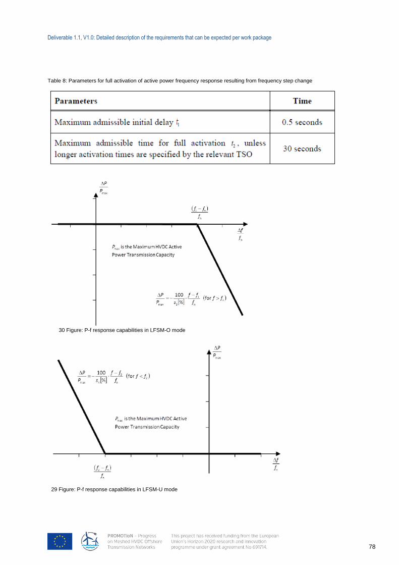
Deliverable 1.1, V1.0: Detailed description of the requirements that can be expected per work package
78
30 Figure: P-f response capabilities in LFSM-O mode
29 Figure: P-f response capabilities in LFSM-U mode
Table 8: Parameters for full activation of active power frequency response resulting from frequency step change
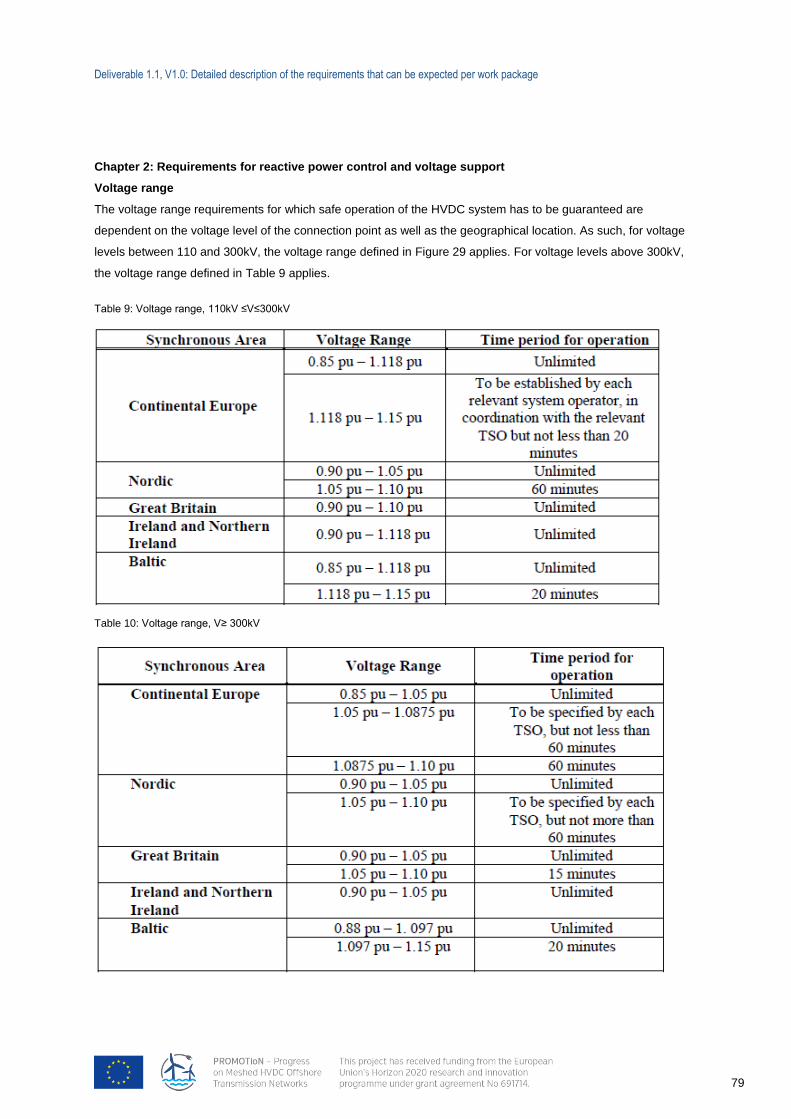
Deliverable 1.1, V1.0: Detailed description of the requirements that can be expected per work package
79
Chapter 2: Requirements for reactive power control and voltage support
Voltage range
The voltage range requirements for which safe operation of the HVDC system has to be guaranteed are
dependent on the voltage level of the connection point as well as the geographical location. As such, for voltage
levels between 110 and 300kV, the voltage range defined in Figure 29 applies. For voltage levels above 300kV,
the voltage range defined in Table 9 applies.
Table 9: Voltage range, 110kV ≤V≤300kV
Table 10: Voltage range, V≥ 300kV
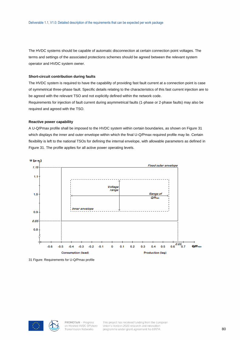
Deliverable 1.1, V1.0: Detailed description of the requirements that can be expected per work package
80
31 Figure: Requirements for U-Q/Pmax profile
The HVDC systems should be capable of automatic disconnection at certain connection point voltages. The
terms and settings of the associated protections schemes should be agreed between the relevant system
operator and HVDC system owner.
Short-circuit contribution during faults
The HVDC system is required to have the capability of providing fast fault current at a connection point is case
of symmetrical three-phase fault. Specific details relating to the characteristics of this fast current injection are to
be agreed with the relevant TSO and not explicitly defined within the network code.
Requirements for injection of fault current during asymmetrical faults (1-phase or 2-phase faults) may also be
required and agreed with the TSO.
Reactive power capability
A U-Q/Pmax profile shall be imposed to the HVDC system within certain boundaries, as shown on Figure 31
which displays the inner and outer envelope within which the final U-Q/Pmax required profile may lie. Certain
flexibility is left to the national TSOs for defining the internal envelope, with allowable parameters as defined in
Figure 31. The profile applies for all active power operating levels.
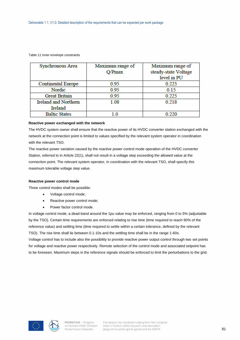
Deliverable 1.1, V1.0: Detailed description of the requirements that can be expected per work package
81
Table 11 Inner envelope constraints
Reactive power exchanged with the network
The HVDC system owner shall ensure that the reactive power of its HVDC converter station exchanged with the
network at the connection point is limited to values specified by the relevant system operator in coordination
with the relevant TSO.
The reactive power variation caused by the reactive power control mode operation of the HVDC converter
Station, referred to in Article 22(1), shall not result in a voltage step exceeding the allowed value at the
connection point. The relevant system operator, in coordination with the relevant TSO, shall specify this
maximum tolerable voltage step value.
Reactive power control mode
Three control modes shall be possible:
Voltage control mode;
Reactive power control mode;
Power factor control mode.
In voltage control mode, a dead-band around the 1pu value may be enforced, ranging from 0 to 5% (adjustable
by the TSO). Certain time requirements are enforced relating to rise time (time required to reach 90% of the
reference value) and settling time (time required to settle within a certain tolerance, defined by the relevant
TSO). The rise time shall lie between 0.1-10s and the settling time shall be in the range 1-60s.
Voltage control has to include also the possibility to provide reactive power output control through two set points
for voltage and reactive power respectively. Remote selection of the control mode and associated setpoint has
to be foreseen. Maximum steps in the reference signals should be enforced to limit the perturbations to the grid.
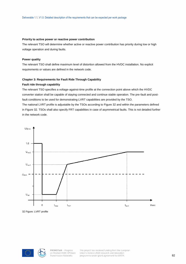
Deliverable 1.1, V1.0: Detailed description of the requirements that can be expected per work package
82
32 Figure: LVRT profile
Priority to active power or reactive power contribution
The relevant TSO will determine whether active or reactive power contribution has priority during low or high
voltage operation and during faults.
Power quality
The relevant TSO shall define maximum level of distortion allowed from the HVDC installation. No explicit
requirements or values are defined in the network code.
Chapter 3: Requirements for Fault Ride Through Capability
Fault ride through capability
The relevant TSO specifies a voltage-against-time profile at the connection point above which the HVDC
converter station shall be capable of staying connected and continue stable operation. The pre-fault and post-
fault conditions to be used for demonstrating LVRT capabilities are provided by the TSO.
The national LVRT profile is adjustable by the TSOs according to Figure 32 and within the parameters defined
in Figure 32. TSOs shall also specify FRT capabilities in case of asymmetrical faults. This is not detailed further
in the network code.
Deliverable 1.1, V1.0: Detailed description of the requirements that can be expected per work package
83
Table 12: Parameter range for definition of the LVRT profile
The TSO may specify voltages (Ublock) at the connection points whereby the HVDC system is allowed to block
(meaning remaining connected but with no active or reactive power contribution for a certain duration to be
defined by the TSO).
Post-fault active power recovery
The relevant TSO shall specify the magnitude and time profile of active power recovery that the HVDC system
shall be capable of providing.
Recovery from dc faults
HVDC systems including DC lines shall be capable of fast recovery from transient faults within the HVDC
system. No additional details are provided in the network code.
Chapter 4: Requirements for control
Energisation and synchronisation
Limits on acceptable transients during these operations shall be enforced by the relevant TSO, with the level not
exceeding 5% of pre-synchronisation voltage.
Interaction between HVDC systems and other plants and equipment
Upon the demand of the TSO, a study may be required to demonstrate that no negative interaction occurs
between HVDC converter stations and nearby electrical equipment.
The relevant TSO may specify transient levels of performance associated with events for the individual HVDC
system or collectively across commonly impacted HVDC systems. This specification may be provided to protect
the integrity of both TSO equipment and that of grid users in a manner consistent with its national code.
Deliverable 1.1, V1.0: Detailed description of the requirements that can be expected per work package
84
Power oscillation damping capability
The HVDC system shall be capable of contributing to the damping of power oscillations in connected AC
networks. The TSO shall provide the frequency range for which damping is to be provided and final settings for
the damping controller are agreed between the HVDC system owner and the relevant TSO. The criteria such as
allowable damping level or tuning methodology are not addressed in the document. It is only stated that the
introduction of the HVDC system should not lead to un-damped oscillations in active or reactive power of the
HVDC system and should not degrade the damping of the system. No specific damping criteria or parameter
tuning methodology/procedure are described within the network code.
Subsynchronous torsional interaction damping capability
The HVDC system shall be capable of contributing to electrical damping of sub-synchronous torsional
interaction (SSTI). The studies are to be conducted by the HVDC system owner, yet may be performed or
reviewed by the relevant TSO, yet are performed depending on input data from the relevant TSO such as
system conditions for which SSTI occurs. The criteria and procedure for conducting this analysis are not
described in the network code.
Any necessary mitigating actions identified by the studies, and reviewed by the relevant TSOs, shall be
undertaken by the HVDC system owner as part of the connection of the new HVDC converter station.
Network characteristics
The relevant TSO shall make available the pre-fault and post-fault conditions for calculations of the minimum
and maximum short circuit power at the connection points. The HVDC system shall be capable of operating
within the range of short power and network characteristics specified by the relevant system operator.
Network equivalents describing the behaviour of the system at the connection points should be provided by the
relevant TSOs to HVDC system owners to enable the realisation of different studies for the design phase.
Chapter 5: Requirements for protection devices and settings
Electrical protection and settings
The relevant system operator shall specify, in coordination with the relevant TSO, the schemes and settings
necessary to protect the network taking into account the characteristics of the HVDC system.
Priority ranking of protection and control
The HVDC system owner shall organise its protections and control devices in compliance with the following
priority ranking, in decreasing order of importance:
Network system and HVDC system protection;
Active power control for emergency assistance;
Synthetic inertia, if applicable;
Automatic remedial actions;
LFSM;
FSM and frequency control;
Power gradient constraint.
Deliverable 1.1, V1.0: Detailed description of the requirements that can be expected per work package
85
Changes to protection and control schemes and settings
The parameters of the different control modes and the protection settings shall be changeable in the HVDC
converter station, if required by the relevant system operator or the relevant TSO.
Chapter 6: Requirements for power system restoration
Black start
The HVDC system owner may submit an offer for providing black start services to the relevant TSO. The HVDC
system should be able to synchronize within the voltage and frequency operating range. Wider ranges can be
specified by the relevant TSO in order to restore system security. The relevant TSO and HVDC system owner
shall agree on the capacity and availability of the black start capability and the operational procedure.
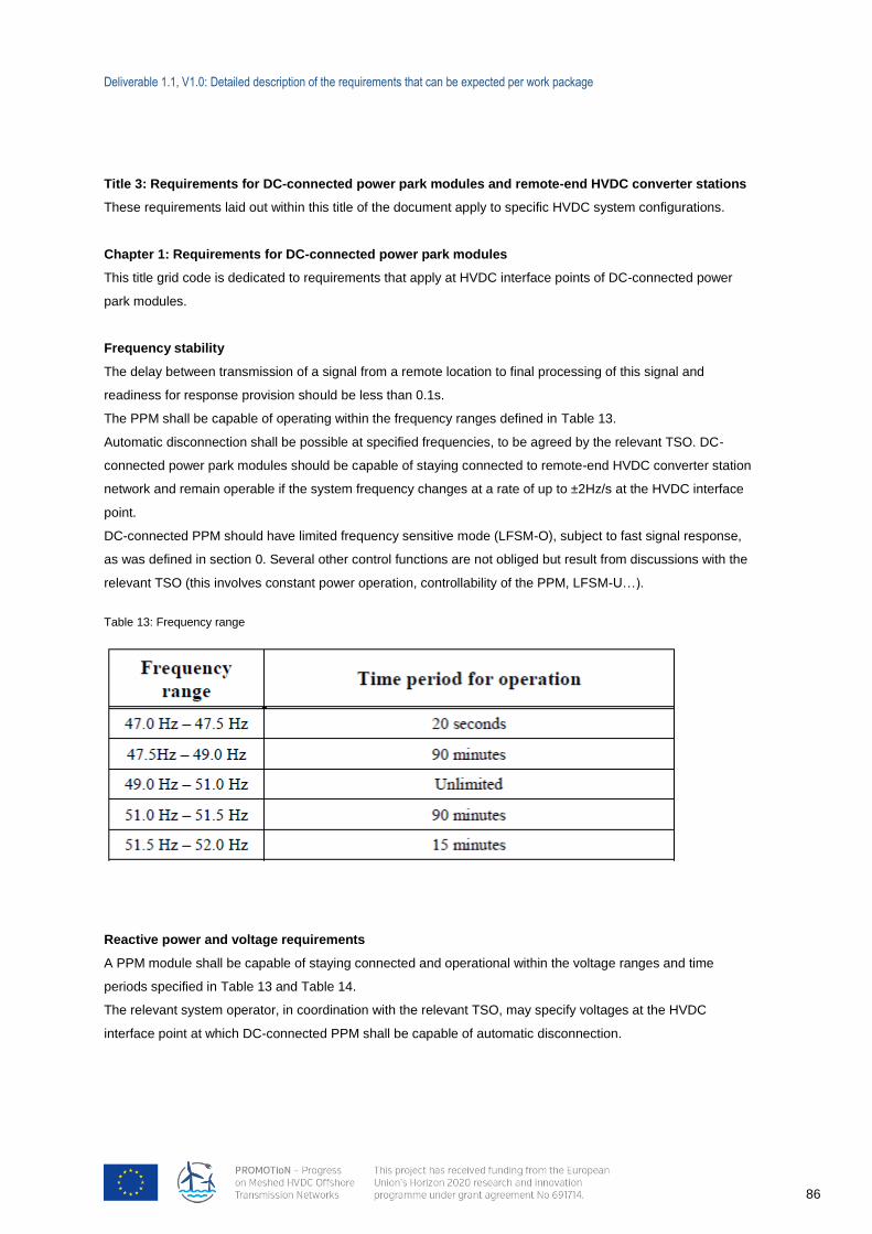
Deliverable 1.1, V1.0: Detailed description of the requirements that can be expected per work package
86
Title 3: Requirements for DC-connected power park modules and remote-end HVDC converter stations
These requirements laid out within this title of the document apply to specific HVDC system configurations.
Chapter 1: Requirements for DC-connected power park modules
This title grid code is dedicated to requirements that apply at HVDC interface points of DC-connected power
park modules.
Frequency stability
The delay between transmission of a signal from a remote location to final processing of this signal and
readiness for response provision should be less than 0.1s.
The PPM shall be capable of operating within the frequency ranges defined in Table 13.
Automatic disconnection shall be possible at specified frequencies, to be agreed by the relevant TSO. DC-
connected power park modules should be capable of staying connected to remote-end HVDC converter station
network and remain operable if the system frequency changes at a rate of up to ±2Hz/s at the HVDC interface
point.
DC-connected PPM should have limited frequency sensitive mode (LFSM-O), subject to fast signal response,
as was defined in section 0. Several other control functions are not obliged but result from discussions with the
relevant TSO (this involves constant power operation, controllability of the PPM, LFSM-U…).
Table 13: Frequency range
Reactive power and voltage requirements
A PPM module shall be capable of staying connected and operational within the voltage ranges and time
periods specified in Table 13 and Table 14.
The relevant system operator, in coordination with the relevant TSO, may specify voltages at the HVDC
interface point at which DC-connected PPM shall be capable of automatic disconnection.
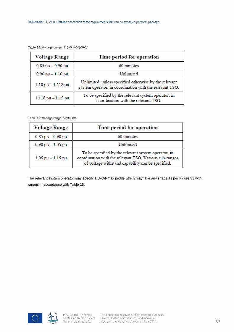
Deliverable 1.1, V1.0: Detailed description of the requirements that can be expected per work package
87
Table 14: Voltage range, 110kV ≤V≤300kV
Table 15: Voltage range, V≥300kV
The relevant system operator may specify a U-Q/Pmax profile which may take any shape as per Figure 33 with
ranges in accordance with Table 15.
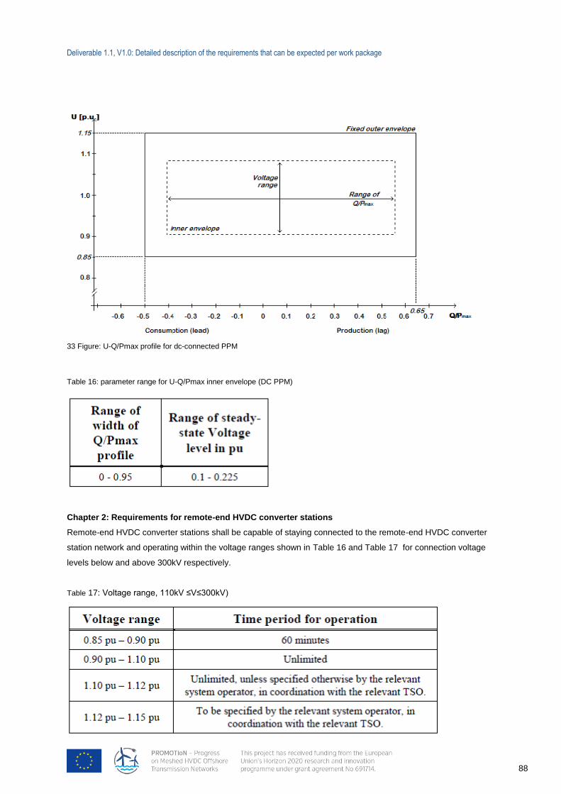
Deliverable 1.1, V1.0: Detailed description of the requirements that can be expected per work package
88
33 Figure: U-Q/Pmax profile for dc-connected PPM
Table 16: parameter range for U-Q/Pmax inner envelope (DC PPM)
Chapter 2: Requirements for remote-end HVDC converter stations
Remote-end HVDC converter stations shall be capable of staying connected to the remote-end HVDC converter
station network and operating within the voltage ranges shown in Table 16 and Table 17 for connection voltage
levels below and above 300kV respectively.
Table 17: Voltage range, 110kV ≤V≤300kV)
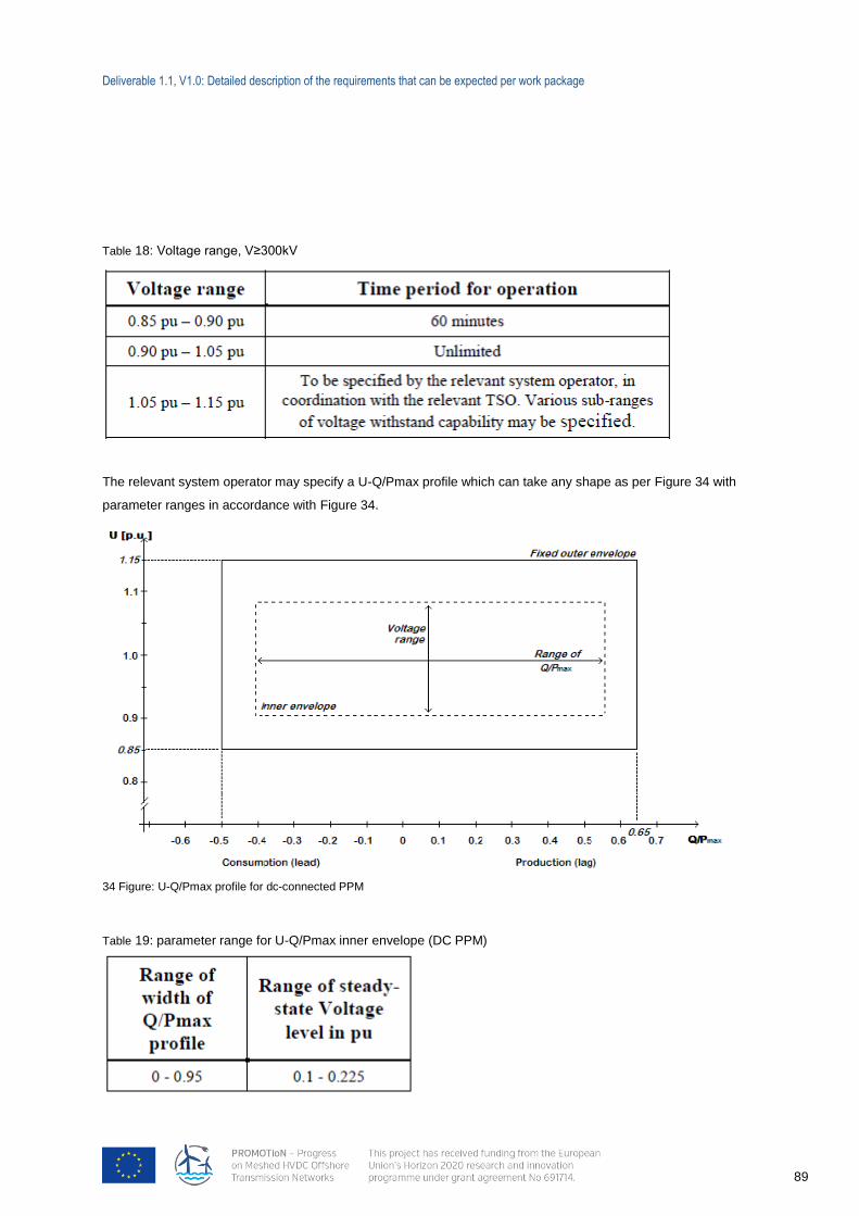
Deliverable 1.1, V1.0: Detailed description of the requirements that can be expected per work package
89
34 Figure: U-Q/Pmax profile for dc-connected PPM
Table 18: Voltage range, V≥300kV
The relevant system operator may specify a U-Q/Pmax profile which can take any shape as per Figure 34 with
parameter ranges in accordance with Figure 34.
Table 19: parameter range for U-Q/Pmax inner envelope (DC PPM)
Deliverable 1.1, V1.0: Detailed description of the requirements that can be expected per work package
90
Title 4: Information exchange and coordination
Operation of HVDC systems
With regard to instrumentation for the operation, each HVDC converter unit of an HVDC system shall be
equipped with an automatic controller capable of receiving instructions from the relevant system operator and
from the relevant TSO. This automatic controller shall be capable of operating the HVDC converter units of the
HVDC system in a coordinated way. The relevant system operator shall specify the automatic controller
hierarchy per HVDC converter unit.
The automatic controller of the HVDC system shall be capable of sending the following signal types to the
relevant system operator:
operational signals, providing at least the following:
start-up signals;
AC and DC voltage measurements;
AC and DC current measurements;
active and reactive power measurements on the AC side;
DC power measurements;
HVDC converter unit level operation in a multi-pole type HVDC converter;
elements and topology status;
FSM, LFSM-O and LFSM-U active power ranges.
alarm signals, providing at least the following:
emergency blocking;
ramp blocking;
fast active power reversal.
The automatic controller referred to in paragraph 1 shall be capable of receiving the following signal types from
the relevant system operator:
operational signals, receiving at least the following:
start-up command;
active power setpoints;
frequency sensitive mode settings;
reactive power, voltage or similar setpoints;
reactive power control modes;
power oscillation damping control;
synthetic inertia.
alarm signals, receiving at least the following:
emergency blocking command;
ramp blocking command;
active power flow direction;
fast active power reversal command.
Deliverable 1.1, V1.0: Detailed description of the requirements that can be expected per work package
91
Parameters and settings
The parameters and settings of the main control functions of an HVDC system shall be agreed between the
HVDC system owner and the relevant system operator, in coordination with the relevant TSO. The parameters
and settings shall be implemented within such a control hierarchy that makes their modification possible if
necessary. These main control functions are at least:
synthetic inertia, if applicable as referred to in Articles 14 and 41;
frequency sensitive modes (FSM, LFSM-O, LFSM-U) referred to in Articles 15, 16 and 17;
frequency control, if applicable, referred to in Article 16;
reactive power control mode, if applicable as referred to in Article 22;
power oscillation damping capability, referred to Article 30;
sub-synchronous torsional interaction damping capability, referred to Article 31.
Fault recording and monitoring
The HVDC system shall be able to provide for fault recording and dynamic system behaviour monitoring of the
following parameters for each HVDC converter stations:
AC and DC voltage;
AC and DC current;
active power;
reactive power;
frequency.
The particulars of the recording equipment (i.e. analogue and digital channels, triggering criteria and sampling
rates) shall be agreed between the HVDC system owner, the relevant system operator and the relevant TSO.
The system shall include an oscillation trigger, with the purpose of detecting poorly damped power oscillations.
Simulation models
The HVDC system owner may have to supply, at the request of the relevant TSO, simulation models which
properly reflect steady-state, dynamic and electromagnetic behaviour to the relevant TSO.
For the purpose of dynamic simulations, the models provided must contain, at least, the following sub-models
(depending on the existence of the mentioned components):
HVDC converter unit models;
AC component models;
DC grid models;
Voltage and power control;
Special control features if applicable e.g. power oscillation damping (POD) function, sub-synchronous
torsional interaction (SSTI) control;
Multi terminal control, if applicable;
HVDC system protection models as agreed between the relevant TSO and the HVDC system owner.
Upon submission of the simulation models to the TSO, a validation report highlighting validity of the models with
respect to actual tests shall be provided as well.
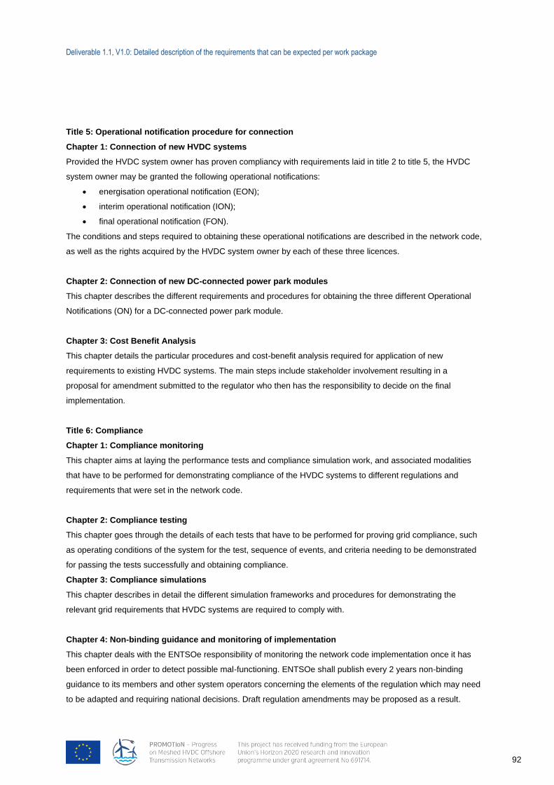
Deliverable 1.1, V1.0: Detailed description of the requirements that can be expected per work package
92
Title 5: Operational notification procedure for connection
Chapter 1: Connection of new HVDC systems
Provided the HVDC system owner has proven compliancy with requirements laid in title 2 to title 5, the HVDC
system owner may be granted the following operational notifications:
energisation operational notification (EON);
interim operational notification (ION);
final operational notification (FON).
The conditions and steps required to obtaining these operational notifications are described in the network code,
as well as the rights acquired by the HVDC system owner by each of these three licences.
Chapter 2: Connection of new DC-connected power park modules
This chapter describes the different requirements and procedures for obtaining the three different Operational
Notifications (ON) for a DC-connected power park module.
Chapter 3: Cost Benefit Analysis
This chapter details the particular procedures and cost-benefit analysis required for application of new
requirements to existing HVDC systems. The main steps include stakeholder involvement resulting in a
proposal for amendment submitted to the regulator who then has the responsibility to decide on the final
implementation.
Title 6: Compliance
Chapter 1: Compliance monitoring
This chapter aims at laying the performance tests and compliance simulation work, and associated modalities
that have to be performed for demonstrating compliance of the HVDC systems to different regulations and
requirements that were set in the network code.
Chapter 2: Compliance testing
This chapter goes through the details of each tests that have to be performed for proving grid compliance, such
as operating conditions of the system for the test, sequence of events, and criteria needing to be demonstrated
for passing the tests successfully and obtaining compliance.
Chapter 3: Compliance simulations
This chapter describes in detail the different simulation frameworks and procedures for demonstrating the
relevant grid requirements that HVDC systems are required to comply with.
Chapter 4: Non-binding guidance and monitoring of implementation
This chapter deals with the ENTSOe responsibility of monitoring the network code implementation once it has
been enforced in order to detect possible mal-functioning. ENTSOe shall publish every 2 years non-binding
guidance to its members and other system operators concerning the elements of the regulation which may need
to be adapted and requiring national decisions. Draft regulation amendments may be proposed as a result.
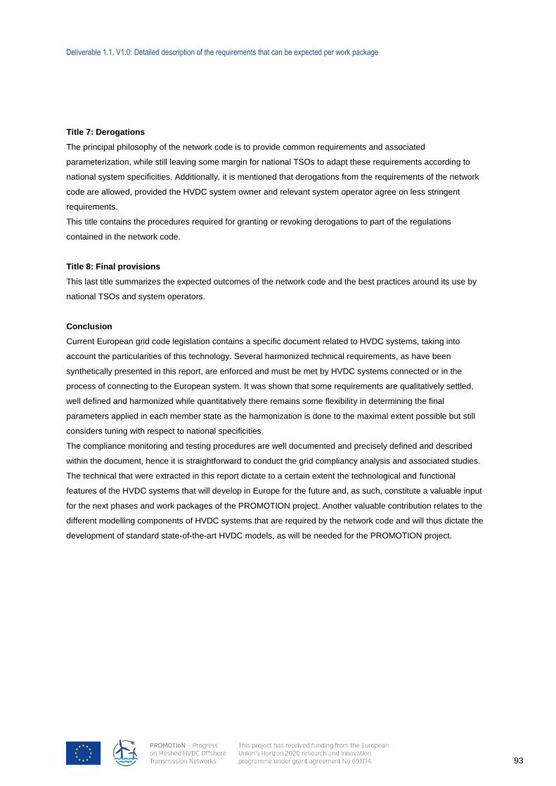
Deliverable 1.1, V1.0: Detailed description of the requirements that can be expected per work package
93
Title 7: Derogations
The principal philosophy of the network code is to provide common requirements and associated
parameterization, while still leaving some margin for national TSOs to adapt these requirements according to
national system specificities. Additionally, it is mentioned that derogations from the requirements of the network
code are allowed, provided the HVDC system owner and relevant system operator agree on less stringent
requirements.
This title contains the procedures required for granting or revoking derogations to part of the regulations
contained in the network code.
Title 8: Final provisions
This last title summarizes the expected outcomes of the network code and the best practices around its use by
national TSOs and system operators.
Conclusion
Current European grid code legislation contains a specific document related to HVDC systems, taking into
account the particularities of this technology. Several harmonized technical requirements, as have been
synthetically presented in this report, are enforced and must be met by HVDC systems connected or in the
process of connecting to the European system. It was shown that some requirements are qualitatively settled,
well defined and harmonized while quantitatively there remains some flexibility in determining the final
parameters applied in each member state as the harmonization is done to the maximal extent possible but still
considers tuning with respect to national specificities.
The compliance monitoring and testing procedures are well documented and precisely defined and described
within the document, hence it is straightforward to conduct the grid compliancy analysis and associated studies.
The technical that were extracted in this report dictate to a certain extent the technological and functional
features of the HVDC systems that will develop in Europe for the future and, as such, constitute a valuable input
for the next phases and work packages of the PROMOTION project. Another valuable contribution relates to the
different modelling components of HVDC systems that are required by the network code and will thus dictate the
development of standard state-of-the-art HVDC models, as will be needed for the PROMOTION project.
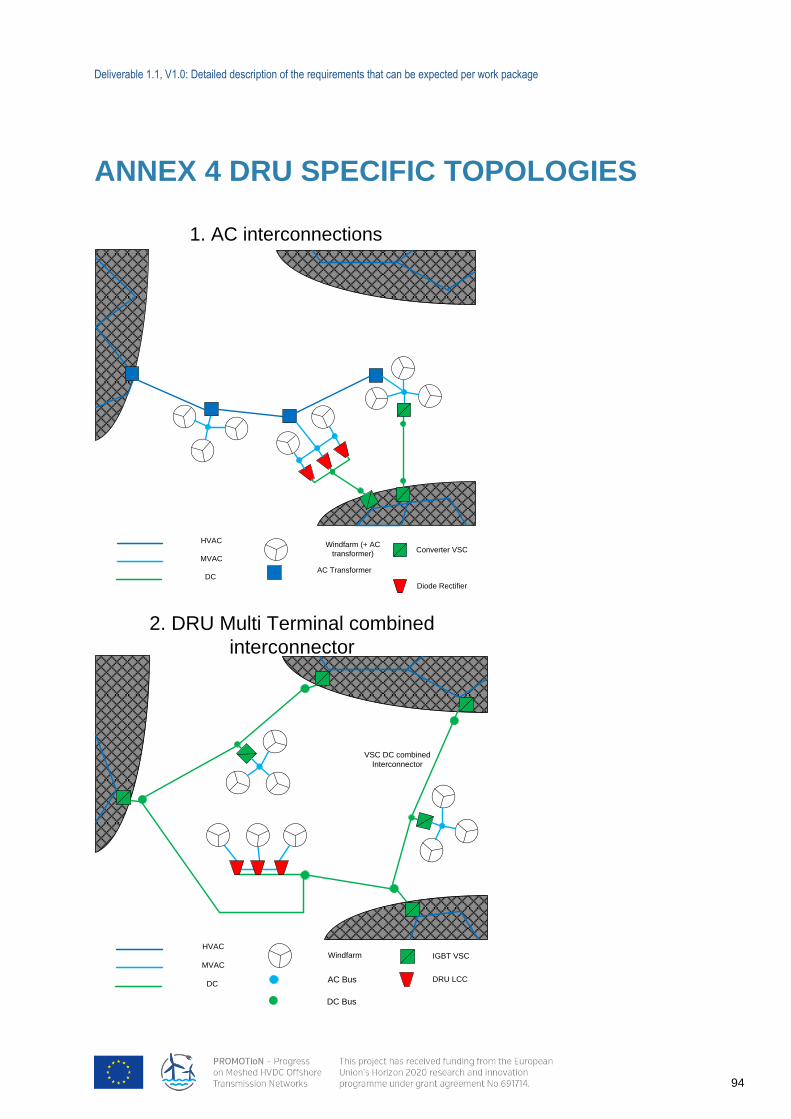
Deliverable 1.1, V1.0: Detailed description of the requirements that can be expected per work package
94
Converter VSC
Diode Rectifier
Windfarm (+ AC
transformer)
HVAC
MVAC
DCAC Transformer
1. AC interconnections
ANNEX 4 DRU SPECIFIC TOPOLOGIES
IGBT VSC
DRU LCC
WindfarmHVAC
MVAC
DC
VSC DC combined
Interconnector
2. DRU Multi Terminal combined
interconnector
DC Bus
AC Bus
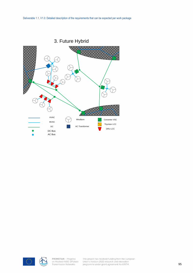
Deliverable 1.1, V1.0: Detailed description of the requirements that can be expected per work package
95
Converter VSC
Thyristor LCC
DRU LCC
WindfarmHVAC
MVAC
DC
3. Future Hybrid
AC Transformer
DC Bus
AC Bus