Embed Size (px)
Citation preview
Cost-effective and flexible 3D printed SOFC stacks for commercial applications - Cell3Ditor
1
DELIVERABLE REPORT
Cell3Ditor – Cost-effective and flexible 3D printed SOFC stacks for commercial applications
Project number: 700266
Project Acronym: Cell3Ditor
Project title: Cost-effective and flexible 3D printed SOFC stacks for commercial applications
Start date of the project: 01/07/2016
Duration of the project: 42 months
Del. no. D1.1
Deliverable name D1.1 - Overall Project Concept and Initial Technical Specifications
WP no WP1
Lead beneficiary IREC
Authors
Type (R/DEM/DEC/OTHER) Report
Dissemin. level (PU/CO/CI) Public
Delivery date from Annex 1 30.09.2016
Actual delivery date
Comments
Deliverable summary
The Cell3ditor project aims at developing 3D printing for mass production of monolithic SOFC stacks reducing manufacturing complexity and increasing cost effectiveness. This deliverable defines the initial specification for stack design and materials, as well as for the printing process and the characterisation of intermediate and final pieces produced.
A multi material 3D printer will be developed to enable the production of a whole SOFC stack in a single manufacturing step. State of the art materials will be used and inks and slurries will be optimised for printing to reach the required thicknesses, gas tightness, porosity and reactivity of the respective layers. Samples of intermediate production steps will be thoroughly characterised throughout the project to assure optimal performance. 3D printing of SOFC allows for greater flexibility in stack design. Therefore a CFD model will be developed to explore optimal stack configuration.
A table at the end of the deliverable summarises the initial specifications for the stack and each intermediate step.
Ref. Ares(2016)5696631 - 30/09/2016
Cost-effective and flexible 3D printed SOFC stacks for commercial applications - Cell3Ditor
2
Content
Cell3Ditor concept ............................................................................................................................................. 3
SOFC materials and design ................................................................................................................................ 5
Materials ........................................................................................................................................................ 5
Stack design ................................................................................................................................................... 5
Initial specifications for final stack: ............................................................................................................... 6
Inks and Slurries ................................................................................................................................................. 6
Slurries ........................................................................................................................................................... 6
Initial specifications for slurries ................................................................................................................. 7
Inks................................................................................................................................................................. 7
Initial technical specification for ink .......................................................................................................... 8
3D printing process ............................................................................................................................................ 9
Development of multi-material 3D printer ................................................................................................. 10
Initial technical specification ....................................................................................................................... 10
Characterisation methodologies ..................................................................................................................... 12
Slurries and inks ........................................................................................................................................... 12
SOFC parts ................................................................................................................................................... 12
SOFC stacks .................................................................................................................................................. 13
Table of characterisation methods .............................................................................................................. 13
Summary of initial technical specifications ..................................................................................................... 14
Cost-effective and flexible 3D printed SOFC stacks for commercial applications - Cell3Ditor
3
Cell3Ditor concept
A Solid Oxide Fuel Cell (SOFC) is a ceramic-based multilayer device that currently involves expensive and time-consuming multi-step manufacturing processes including tape casting, screen printing, firing, shaping and several high-temperature thermal treatments. In addition, these cells are manually assembled into stacks resulting in extra steps for joining and sealing that difficult the standardization and quality control of the final product while introducing weak parts likely to fail. Since current ceramics processing presents strong limitations in shape and extremely complex design for manufacturing (more than 100 steps), industrially fabricated SOFC cells and stacks are expensive and present low flexibility and long time-to-market.
The goal of the Cell3Ditor project is the development of 3D printing of ceramics for mass production of SOFC stacks. This technology allows the fabrication of SOFC stacks with unique features such as monolithic architecture, absence of joints and sealing, thinner elements and embedded fluidics and current collection in only two production steps (printing and sintering). This simplification of the fabrication process reduces the cost and initial investment required and increases the SOFC design flexibility the manufacturing reliability. The focus of the proposal is put on i) large scale manufacturing of printable inks and slurries of SOFC ceramic materials; ii) 3D printing of multi-layer multi-material SOFCs; iii) single step sintering of 3D printed SOFC cells and kW-range stacks.
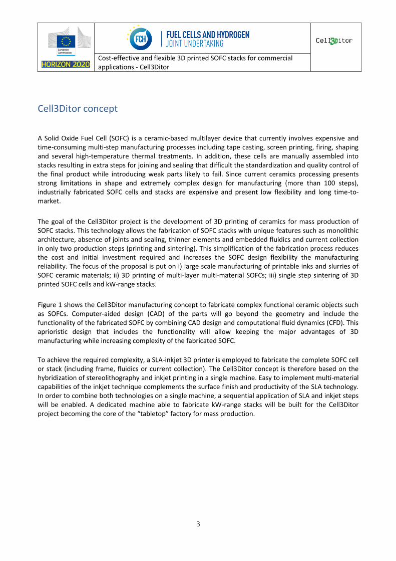
Figure 1 shows the Cell3Ditor manufacturing concept to fabricate complex functional ceramic objects such as SOFCs. Computer-aided design (CAD) of the parts will go beyond the geometry and include the functionality of the fabricated SOFC by combining CAD design and computational fluid dynamics (CFD). This aprioristic design that includes the functionality will allow keeping the major advantages of 3D manufacturing while increasing complexity of the fabricated SOFC.
To achieve the required complexity, a SLA-inkjet 3D printer is employed to fabricate the complete SOFC cell or stack (including frame, fluidics or current collection). The Cell3Ditor concept is therefore based on the hybridization of stereolithography and inkjet printing in a single machine. Easy to implement multi-material capabilities of the inkjet technique complements the surface finish and productivity of the SLA technology. In order to combine both technologies on a single machine, a sequential application of SLA and inkjet steps will be enabled. A dedicated machine able to fabricate kW-range stacks will be built for the Cell3Ditor project becoming the core of the “tabletop” factory for mass production.
Cost-effective and flexible 3D printed SOFC stacks for commercial applications - Cell3Ditor
4
Figure 1: The Cell3Ditor manufacturing concept
The printing machine will be fed with printable slurries and inks based on ceramic nanomaterials. While the SLA slurries will be fabricated by mixing previously synthesized powders with the organic vehicle, the nanodispersions for inkjet will be prepared by continuous hydrothermal synthesis in a single step. Both methodologies allow tailoring the particle size, size distribution and morphology of the nanomaterial as well as the organic formulation. This versatility will allow achieving desired composites and overcoming manufacturing issues such as reducing the sintering temperature and selectively limit the grain growth (or enhance the sinterability) throughout the parts.
Finally, the complete SOFC stack will be sintered in a single step to result in a monolithic device. The proper selection of materials (TECs), the right formulation of the inks and slurries as well as the definition of a structural skeleton of YSZ will allow an isotropic shrinkage of the whole device and the coexistence of dense and porous parts.
The Cell3Ditor concept mainly pursues increasing the cost-effectiveness and reducing the environmental impact by simplifying the manufacturing process of SOFC stacks. Apart from the obvious simplification resulting from a two-step (shaping and sintering) fabrication process and the reduction of waste material by employing additive manufacturing, the project reduces the cost associated to assembly of the whole stack and implementation of the final system, e.g. current collection, sealants, fluidics, etc.
Cost-effective and flexible 3D printed SOFC stacks for commercial applications - Cell3Ditor
5
SOFC materials and design
3D printing of SOFC offers a bigger flexibility in stack geometry compared to conventional methods but it requires the materials to be printable in addition to function well inside the stack.
Materials
The 3D printed SOFC stack will be fabricated by using the state-of-the-art SOFC cell materials: stabilized zirconia as electrolyte and 3D scaffold of the whole device, NiO for anode active material, lanthanum strontium manganite as cathode active material and doped alkaline earth metals titanate (La0.4Ca0.6Ti1-
xMnxO3-δ, x=0.6 as starting point) as interconnector. The electrodes will consist on composites of the electrolyte and the corresponding active material to align the thermal expansion coefficient and avoid nickel agglomeration on the anode side. These materials will make it possible to sinter all layers together in a single sintering step at temperatures below 1300°C.
While the electrolyte and interconnect materials will be fully densified, the electrodes will be fabricated to generate porous structures (also with embedded gas flow channels). This will be achieved by fine tuning the printable inks and slurries. In order to improve compatibility between SLA and ink-jet deposited layers, photocurable media will be used as a first aproach in both cases (see section “Inks and Slurries”).
Stack design
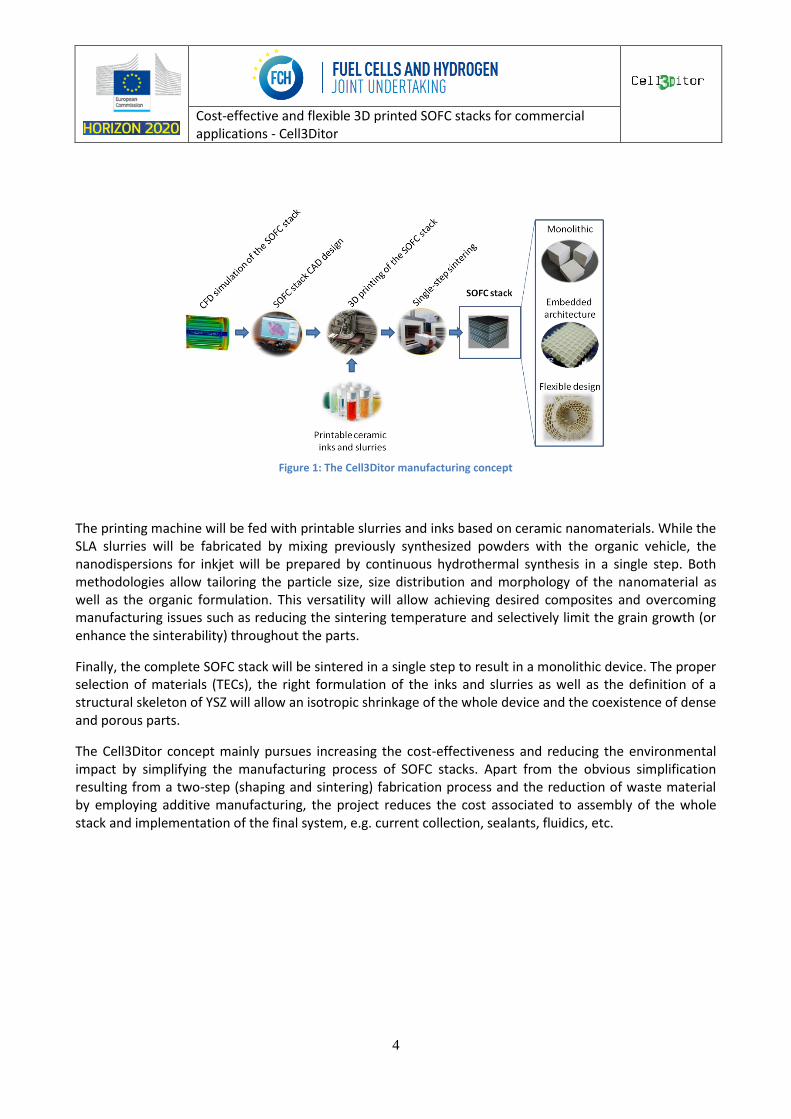
Before the fabrication of the monolithic SOFC stack, the design of the final device will be optimized by simulation of the different architectures using Computational Fluid Dynamics (CDF).
For the expected operation conditions aprioristic CFD models of the whole stack will be used for validating the details of the geometries to be printed (flow rates, pressure maps, temperature maps, thermal stresses, current density and distribution, etc.). These types of numerical simulations are the only way to predict the performance of complex geometries (including multi-scale parts) fabricated with different materials and involving different physical and chemical processes. After this design validation, the 3D printing of different SOFC stacks, with increasing size and complexity, will be carried out.
Figure 2: Stack design
Cost-effective and flexible 3D printed SOFC stacks for commercial applications - Cell3Ditor
6
Initial specifications for final stack:
The top-level requirements of the final monolithic SOFC stack will be:
- Maximum dimensions of the SOFC stack 12x12x10 cm3
- Thickness of layers:
o Anode: between 10-250 μm, determined by size of gas channels
o Cathode: between 10-250 μm, determined by size of gas channels
o Electrolyte: < 100 µm
o Interconnector: < 50 µm
- 5 kW SOFC stack operated at 850ºC under humidified hydrogen
- Integration of fluidics and current collection in the monolithic device
Inks and Slurries
For printing the SOFC inks and slurries have to be prepared that include the required ceramic material, a binder and possibly dilutants and pore formers. Theses inks and slurries have to be optimized in order to achieve the required conductivity, electrochemical performance and gas percolation at the final layer in the SOFC stack.
Slurries
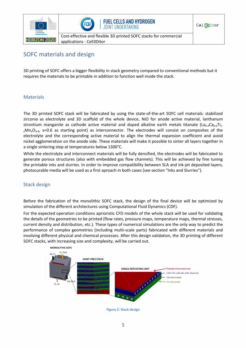
The stereolithography (SLA) printing process is based on a doctor blade that homogeneously covers the surface with a photocurable slurry. A laser then defines the desired motif by selective photocuring the slurry. The surface is then covered again with slurry and cured to add another layer. Photocurable slurries based on YSZ will be formulated and prepared for producing dense electrolyte layers of a thickness below 30 μm using SLA. The goal within this project is to optimize the formulation of inks and slurries based on ceramic nanomaterials and to tailor the microstructure of the deposited layers to reach the expected functionality.
Figure 3: CERAMAKER printer from 3DCer and details of the printing process (doctor blade and laser photo-curing)
Cost-effective and flexible 3D printed SOFC stacks for commercial applications - Cell3Ditor
7
Ceramic stereolithography involves polymerization of a UV-curable system consisting of a suspension of ceramic particles in a photopolymer. In this task, a UV curable system based on a low viscosity photopolymerisable monomer, with a refractive index of around 1.40, and a photoinitiator absorbing in the range of the UV source will be the base for dispersing a commercial YSZ nanopowder. The final slurry should show a low dispersion of the UV light employed in the curing step at SLA and a post-processing good sinterability at low T, Ts ≤1300ºC. This trade off is crucial for the SLA printing process since i) the introduction of small (<1µm) ceramic particles in the UV-curable system increases the scattering of the light, therefore reducing the resolution and increasing the processing time and ii) increasing the particle size reduces the sintering reactivity forcing elevated temperatures to fully densify the ceramics. The optimization of these slurries will be carried out to i) stabilize the ceramic pastes and prevent agglomeration and settling of the ceramic particles (dispersant), and ii) confer the system a high yield stress value to support the piece during fabrication (thickening agent). The rheological behaviour of highly loaded ceramic systems will be optimized by means of adequate additives to allow suitable layer spreading and to achieve homogeneous green microstructure. The final SOFC stack will contain around 1kg of YSZ coming from SLA printing.
Initial specifications for slurries
The main parameters expected for the final slurry will be:
- Ceramic load concentration above 50 vol% powder
- Yield stress value >400 Pa
- Viscosity of more than 10,000 Pa·s at rest
- Shear thinning behaviour for deposition of 10 µm-thick layers
- Quick UV-curability and reduced light scattering (n~1.4)
- Good sinterability at low T, Ts ≤1300ºC
Inks
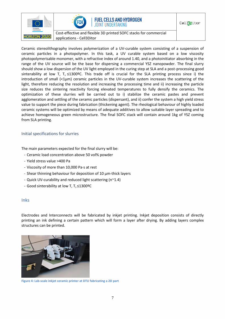
Electrodes and Interconnects will be fabricated by inkjet printing. Inkjet deposition consists of directly printing an ink defining a certain pattern which will form a layer after drying. By adding layers complex structures can be printed.
Figure 4: Lab-scale inkjet ceramic printer at DTU fabricating a 2D part
Cost-effective and flexible 3D printed SOFC stacks for commercial applications - Cell3Ditor
8
The inks used for the electrodes and the interconnector require synthesis of dispersed nanoparticles and nanocomposites of stabilized Zirconia, NiO, Sr-doped LaMnO3 (LSM) and LayCa1-yTi1-xMnxO3-d (LCTM) for direct use in inkjet printing, allowing porosity control and good interconnectivity in composites deposited by inkjet after firing at the sintering temperature .
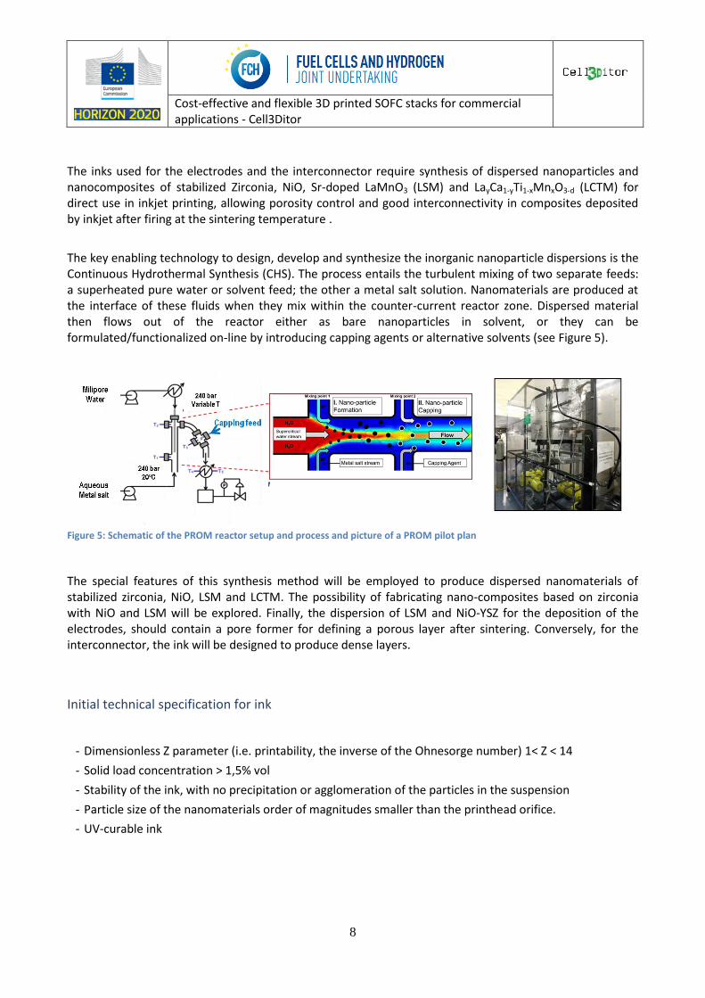
The key enabling technology to design, develop and synthesize the inorganic nanoparticle dispersions is the Continuous Hydrothermal Synthesis (CHS). The process entails the turbulent mixing of two separate feeds: a superheated pure water or solvent feed; the other a metal salt solution. Nanomaterials are produced at the interface of these fluids when they mix within the counter-current reactor zone. Dispersed material then flows out of the reactor either as bare nanoparticles in solvent, or they can be formulated/functionalized on-line by introducing capping agents or alternative solvents (see Figure 5).
Figure 5: Schematic of the PROM reactor setup and process and picture of a PROM pilot plan
The special features of this synthesis method will be employed to produce dispersed nanomaterials of stabilized zirconia, NiO, LSM and LCTM. The possibility of fabricating nano-composites based on zirconia with NiO and LSM will be explored. Finally, the dispersion of LSM and NiO-YSZ for the deposition of the electrodes, should contain a pore former for defining a porous layer after sintering. Conversely, for the interconnector, the ink will be designed to produce dense layers.
Initial technical specification for ink
- Dimensionless Z parameter (i.e. printability, the inverse of the Ohnesorge number) 1< Z < 14
- Solid load concentration > 1,5% vol
- Stability of the ink, with no precipitation or agglomeration of the particles in the suspension
- Particle size of the nanomaterials order of magnitudes smaller than the printhead orifice.
- UV-curable ink
Cost-effective and flexible 3D printed SOFC stacks for commercial applications - Cell3Ditor
9
3D printing process
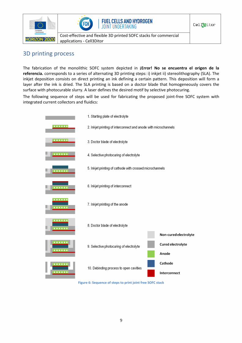
The fabrication of the monolithic SOFC system depicted in ¡Error! No se encuentra el origen de la referencia. corresponds to a series of alternating 3D printing steps: i) inkjet ii) stereolithography (SLA). The inkjet deposition consists on direct printing an ink defining a certain pattern. This deposition will form a layer after the ink is dried. The SLA printing is based on a doctor blade that homogeneously covers the surface with photocurable slurry. A laser defines the desired motif by selective photocuring.
The following sequence of steps will be used for fabricating the proposed joint-free SOFC system with integrated current collectors and fluidics:
Figure 6: Sequence of steps to print joint free SOFC stack
Cost-effective and flexible 3D printed SOFC stacks for commercial applications - Cell3Ditor
10
Development of multi-material 3D printer
A new dedicated hybrid SLA-inkjet ceramic printer machine for the fabrication of multi-material complex geometries will be developed. Piezoelectric Drop-On-Demand (Piezo DOD) technology is the first choice for the printing head (among commercially available units) since it is an isothermal process able to work with a broad range of inks, allowing better control of the volume and shape of the ink droplet, and also requiring relatively low capital investment.
After the selection of the parts, mechanical assembly and, more importantly, software development will be carried out with the main objective to keep the essential advantages and fabrication scheme of the ceramic additive manufacturing (CAM):
- CAD design of the product
- CAS file creation and file conversion to STL format
- Computerized slicing of the part to be manufactured into layers, inclusion of the printer parameters (trajectory of the laser, energy density, inkjet print head position, multi-material definition …) and layer by layer production.
- Debinding and sintering
Another major goal is to ensure the compatibility of the inkjet and SLA 3D printing technologies and the fabrication sequence.
As described in Figure 6 the most suitable repeating sequence for maximizing the shape possibilities of the multimaterial object (including connectivity of the inkjet printed materials in the z-axis) consists in:
- Deposition of a layer of the stabilized zirconia photocurable slurry by doctor blade
- Polymerization of the desired pattern by UV-light with controlled energy density from the laser
- Deposition of the desired pattern by inkjet printing
- Polymerization of the inkjet printed pattern
- Deposition of a new layer of zirconia
A fine tuning of the formulation of the inks for the inkjet printing will be necessary to maximize the compatibility of the processes. Two main aspects will be analyzed referred to the compatibility:
- Interaction of the ink with the SLA paste/polymerized substrate
- Determination of the curing and adherence of the inks onto SLA substrates
These two aspects will determine the lateral resolution of the system and the interface defined between two different materials.
Initial technical specification
The overall manufacturing parameters of the final system will be:
- Maximum printable volume: 30x30x10 cm.
- Layer thickness in the range between 10-250 μm
Cost-effective and flexible 3D printed SOFC stacks for commercial applications - Cell3Ditor
11
- Lateral resolution <100 μm
- Multi-material deposition: 1 material by SLA and 4 by inkjet printing
- Capability of deposition of more than 100 layers/hour
Cost-effective and flexible 3D printed SOFC stacks for commercial applications - Cell3Ditor
12
Characterisation methodologies
A wide range of characterisation methods will be applied to assure optimal performance of materials, processing methods and components.
Slurries and inks For the optimization of the rheological behaviour of the slurries, zeta potential, rheology and light scattering spectroscopy will be carried out.
For the inks, the printability (including rheological and physical properties of the suspensions) will be analyzed by the following schema: determination of the zeta potential and particle size dispersion stability as a function of time, surface tension of the ink in relation to the surface to be printed, and evaluation of the rheological properties of the suspension during and after the printing.
SOFC parts
The characterization of the sintered objects will be carried out with the main aim of defining compositional, structural and microstructural mapping of the whole object. Spatially resolved techniques would be therefore preferred. Determining the porosity of the different parts of the sintered body, analyzing the reactivity of the different materials at the corresponding interfaces, studying the quality of the multi-material interfaces and defect mapping (voids, delaminations, etc) will be the primary objective. A long list of characterization techniques capable to cover this major goal will be available, among other, micro-Raman, micro-XRD, SEM-EDX, X-Ray Fluorescence, FIB-SEM, ToF-SIMS, STEM-EELS or XPS.
Apart from providing an accurate characterization to improve the fabrication process, there will be specific exploration of in-situ metrology able to offer simple and cost-effective tools for rapidly evaluating the quality of the fabricated objects. X-ray tomography will be specifically evaluated by dedicated systems.
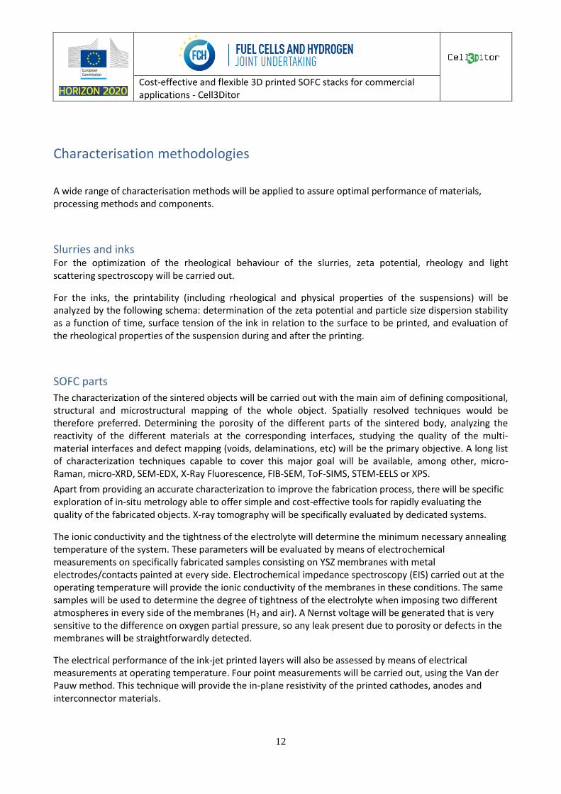
The ionic conductivity and the tightness of the electrolyte will determine the minimum necessary annealing temperature of the system. These parameters will be evaluated by means of electrochemical measurements on specifically fabricated samples consisting on YSZ membranes with metal electrodes/contacts painted at every side. Electrochemical impedance spectroscopy (EIS) carried out at the operating temperature will provide the ionic conductivity of the membranes in these conditions. The same samples will be used to determine the degree of tightness of the electrolyte when imposing two different atmospheres in every side of the membranes (H2 and air). A Nernst voltage will be generated that is very sensitive to the difference on oxygen partial pressure, so any leak present due to porosity or defects in the membranes will be straightforwardly detected.
The electrical performance of the ink-jet printed layers will also be assessed by means of electrical measurements at operating temperature. Four point measurements will be carried out, using the Van der Pauw method. This technique will provide the in-plane resistivity of the printed cathodes, anodes and interconnector materials.
Cost-effective and flexible 3D printed SOFC stacks for commercial applications - Cell3Ditor
13
SOFC stacks
Determining the porosity of the different parts of the sintered body, analysing the reactivity of the different materials at the corresponding interfaces, studying the quality of the multi-material interfaces and defect mapping (voids, delaminations, etc.) will be the primary objective. A long list of characterization techniques capable to cover this major goal will be employed, among other, micro-Raman, micro-XRD, SEM-EDX, X-Ray Fluorescence, FIB-SEM, ToF-SIMS, STEM-EELS or XPS.
On the other hand, the electrochemical performance of the cells will be evaluated. For this, the total resistance and the arising voltage/current characteristics will be measured. EIS will also be used for the study of the behaviour of the components under operation.
Apart from an accurate characterization to improve the fabrication process in-situ metrology able to offer simple and cost-effective tools for rapidly evaluating the quality of the fabricated objects will be explored.
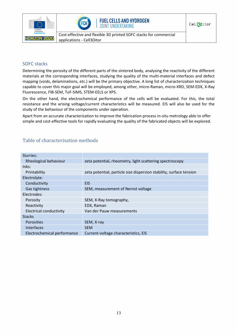
Table of characterisation methods
Slurries:
Rheological behaviour zeta potential, rheometry, light scattering spectroscopy
Inks:
Printability zeta potential, particle size dispersion stability, surface tension
Electrolyte:
Conductivity EIS
Gas tightness SEM, measurement of Nernst voltage
Electrodes:
Porosity SEM, X-Ray tomography,
Reactivity EDX, Raman
Electrical conductivity Van der Pauw measurements
Stacks
Porosities SEM, X-ray
Interfaces SEM
Electrochemical performance Current-voltage characteristics, EIS
Cost-effective and flexible 3D printed SOFC stacks for commercial applications - Cell3Ditor
14
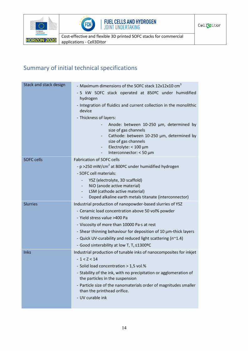
Summary of initial technical specifications
Stack and stack design - Maximum dimensions of the SOFC stack 12x12x10 cm3
- 5 kW SOFC stack operated at 850ºC under humidified hydrogen
- Integration of fluidics and current collection in the monolithic device
- Thickness of layers:
- Anode: between 10-250 μm, determined by size of gas channels
- Cathode: between 10-250 μm, determined by size of gas channels
- Electrolyte: < 100 µm - Interconnector: < 50 µm
SOFC cells Fabrication of SOFC cells
- p >250 mW/cm2 at 800ºC under humidified hydrogen
- SOFC cell materials:
- YSZ (electrolyte, 3D scaffold) - NiO (anode active material) - LSM (cathode active material) - Doped alkaline earth metals titanate (interconnector)
Slurries Industrial production of nanopowder-based slurries of YSZ
- Ceramic load concentration above 50 vol% powder
- Yield stress value >400 Pa
- Viscosity of more than 10000 Pa·s at rest
- Shear thinning behaviour for deposition of 10 µm-thick layers
- Quick UV-curability and reduced light scattering (n~1.4)
- Good sinterability at low T, Ts ≤1300ºC
Inks Industrial production of tunable inks of nanocomposites for inkjet
- 1 < Z < 14
- Solid load concentration > 1,5 vol.%
- Stability of the ink, with no precipitation or agglomeration of the particles in the suspension
- Particle size of the nanomaterials order of magnitudes smaller than the printhead orifice.
- UV curable ink
Cost-effective and flexible 3D printed SOFC stacks for commercial applications - Cell3Ditor
15
3D printer Hybridization of SLA and inkjet in a dedicated printer
- Maximum printable volume: 30x30x10 cm.
- Layer thickness in the range between 10-250 μm
- Lateral resolution <100 μm
- Multi-material deposition: 1 material by SLA and 4 by inkjet printing
- Capability of deposition of more than 100 layers/hour
- Optimize debinding of multi-material 3D printed objects


![YSZ-STO multilayers obtained by PLD · [4,14,16,17]. In this study YSZ/STO epitaxial heterostructures were prepared by pulsed laser deposition (PLD) in order to investigate the conductivity](https://img.pdfslide.net/doc/110x75/5e7d1d187d832460c10c1bc7/ysz-sto-multilayers-obtained-by-pld-4141617-in-this-study-yszsto-epitaxial.jpg)