Embed Size (px)
Citation preview
Dell EMC Ready Stack: VMware IaaS with Big Cloud Fabric on PowerEdge MX Servers and PowerMax Storage December 2019
H18051
Design Guide
Abstract This design guide describes the architecture, design, configuration, and sizing of a converged infrastructure for VMware IaaS. The infrastructure uses Big Cloud Fabric with Dell EMC PowerEdge MX servers, PowerMax storage, PowerSwitch S-Series switches, and data protection products.
Dell EMC Solutions
Copyright
2 Dell EMC Ready Stack: VMware IaaS with Big Cloud Fabric on PowerEdge MX Servers and PowerMax Storage Design Guide
The information in this publication is provided as is. Dell Inc. makes no representations or warranties of any kind with respect to the information in this publication, and specifically disclaims implied warranties of merchantability or fitness for a particular purpose.
Use, copying, and distribution of any software described in this publication requires an applicable software license. Copyright © 2019 Dell Inc. or its subsidiaries. All Rights Reserved. Dell Technologies, Dell, EMC, Dell EMC and other trademarks are trademarks of Dell Inc. or its subsidiaries. Intel, the Intel logo, the Intel Inside logo and Xeon are trademarks of Intel Corporation in the U.S. and/or other countries. Other trademarks may be trademarks of their respective owners. Published in the USA 12/19 Design Guide H18051.
Dell Inc. believes the information in this document is accurate as of its publication date. The information is subject to change without notice.
Contents
3 Dell EMC Ready Stack: VMware IaaS with Big Cloud Fabric on PowerEdge MX Servers and PowerMax Storage Design Guide
Contents
Chapter 1 Introduction 4 Ready Stack overview ........................................................................................... 5 Key benefits .......................................................................................................... 5 Document purpose ................................................................................................ 7 Audience ............................................................................................................... 7 We value your feedback ........................................................................................ 7
Chapter 2 Ready Stack Architecture 8 Installation and configuration considerations .......................................................... 9 Existing infrastructure requirements ....................................................................... 9 Ready Stack architecture overview ..................................................................... 10 Ready Stack architecture with Big Cloud Fabric .................................................. 10
Chapter 3 Configurations and Specifications 21 Recommended platforms and components .......................................................... 22 Ready Stack scaling ............................................................................................ 23 Design configurations and specifications ............................................................. 24
Chapter 4 Ready Stack Design 33 Compute design .................................................................................................. 34 Network design ................................................................................................... 34 Storage design .................................................................................................... 37 Management design ............................................................................................ 43
Chapter 5 References 47 Dell EMC documentation..................................................................................... 48 VMware documentation ...................................................................................... 48 Big Switch Networks documentation ................................................................... 48
Chapter 1: Introduction
4 Dell EMC Ready Stack: VMware IaaS with Big Cloud Fabric on PowerEdge MX Servers and PowerMax Storage Design Guide
Chapter 1 Introduction
This chapter presents the following topics:
Ready Stack overview ......................................................................................... 5
Key benefits ......................................................................................................... 5
Document purpose ............................................................................................. 7
Audience .............................................................................................................. 7
We value your feedback ..................................................................................... 7
Chapter 1: Introduction
5 Dell EMC Ready Stack: VMware IaaS with Big Cloud Fabric on PowerEdge MX Servers and PowerMax Storage Design Guide
Ready Stack overview Due to more options and increasing complexity, managing IT infrastructure in a data center is becoming increasingly difficult. Changing data center infrastructure that has evolved over time can significantly affect stability, performance, costs, and upgradability.
Dell EMC Ready Stack solutions are proven, tested, and optimized to help organizations meet long-term data center needs for various mixed workloads. This Ready Stack solution provides the simplicity of a complete, yet flexible, validated converged infrastructure (CI) that is based on the following components:
• Dell EMC PowerMax storage
• Dell EMC PowerEdge MX7000 modular chassis
• Dell EMC PowerSwitch S-Series switches—stand alone or as part of Big Cloud Fabric (BCF)
• VMware Infrastructure as a Service (IaaS)
• Big Switch Networks BCF
• Dell EMC Integrated Data Protection Appliance (IDPA) DP4400 backup solution
This solution provides:
• One trusted vendor for all physical CI stack components—compute, storage, networking, and data protection.
• Design and deployment guidance that incorporates validation, interoperability testing, and best practices.
• Design guidance that focuses on scale, flexibility, and high availability.
• A reference architecture that incorporates physical topology diagrams and general connectivity guidelines.
• Unified management and system monitoring through VMware vCenter. Adding the BCF plug-in for VMware vSphere Web Client enables the vCenter administrator to monitor and configure BCF, and to perform virtual machine (VM)-to-VM troubleshooting.
Key benefits This Ready Stack provides the following key benefits:
• Resiliency—The Ready Stack architecture ensures that no single point of failure exists. Redundancy is incorporated in the critical aspects of the Ready Stack, which includes server high-availability features, redundant networking, and multipath storage.
• Virtualization support—We designed this Ready Stack for general-purpose virtualized workloads. Each server is equipped with suitable processing power, memory, and converged network adapters (CNAs) that support Ethernet and Fibre Channel (FC) as required for virtualization.
• Scalability—You can configure this Ready Stack to suit your specific needs for a virtualized infrastructure. The Ready Stack supports flexibility in the form of various
Chapter 1: Introduction
6 Dell EMC Ready Stack: VMware IaaS with Big Cloud Fabric on PowerEdge MX Servers and PowerMax Storage Design Guide
options, such as server model, number of compute servers, server processor model, server memory capacity, type of FC storage, and FC storage capacity.
• Software-defined networking (SDN) with BCF–-BCF SDN provides network automation and operational simplicity with Dell EMC Open Networking switches.
• Powerful all-flash storage—PowerMax storage is a high-end addition to Dell EMC’s broad all-flash portfolio. It is well suited for organizations that are seeking a future-proof scale-out storage architecture that is based on the latest NVMe technology, massive consolidation at scale, and rich data services. Included is PowerMaxOS, an operating system with an integrated machine-learning engine to support next-generation media.
• Integrated data protection—The IDPA DP4400 preconfigured backup solution combines protection storage and software, search, analytics, and simplified management. In addition, Dell EMC RecoverPoint for Virtual Machines provides protection at VM-level granularity with local and remote replication for recovery to any point in time.
• Integrated Dell EMC management—This Ready Stack includes the following Dell EMC and Big Switch management tools:
Dell EMC OpenManage Integration for VMware vCenter—A virtual appliance that enables administrators to view physical host details in VMware vSphere.
Dell EMC Virtual Storage Integrator (VSI)—A vCenter plug-in that enables administrators to view, manage, and optimize storage for vSphere servers and hosts.
Dell EMC Integrated Dell Remote Access Controller 9 (iDRAC9)—An out-of-band (OOB) management tool for Dell EMC PowerEdge rack servers and blade servers. iDRAC9 has its own HTML5-based UI and can be accessed using various methods including SSH, RACADM, and the Redfish API. iDRAC9 Group Manager provides a one-to-many console for accessing the details of multiple servers. Administrators can also use Dell EMC OpenManage Enterprise Modular Edition to manage server content that is accessible through iDRAC9.
OpenManage Enterprise Modular Edition—A comprehensive embedded systems management system. It provides key functions of OpenManage Enterprise management within the chassis for the entire environment and serves as a single management point for compute, storage, and networking. You can simultaneously deploy and monitor multiple chassis, roll out changes and templates faster, and integrate the system with third-party tools.
IDPA System Manager—An HTML5-based UI that provides administrators with configurable dashboards to simplify and automate data protection management, monitoring, and reporting.
BCF Integration for VMware vCenter—Comprehensive network management and automation for VMware virtual environments. Along with Big Switch Networks BCF, the BCF plug-in for vSphere Web Client provides VM administrators a window into the network management of VMs, specifically VM-to-VM network monitoring and troubleshooting.
Chapter 1: Introduction
7 Dell EMC Ready Stack: VMware IaaS with Big Cloud Fabric on PowerEdge MX Servers and PowerMax Storage Design Guide
Document purpose This Ready Stack design guide provides design principles, best practices, architectural guidance, and validated configurations for compute, management, networking, and storage. It includes component specifications for three sample configurations and information about scaling the Ready Stack.
Note: For details about implementing this Ready Stack, see the Dell EMC Ready Stack: VMware IaaS with Big Cloud Fabric on PowerEdge MX Servers and PowerMax Storage Deployment Guide.
Audience This guide is for customers, channel partners, and Dell EMC personnel. We recommend that readers have a working knowledge of virtualization technologies for servers, storage, networking, and data protection.
We value your feedback Dell EMC and the authors of this document welcome your feedback on the solution and the solution documentation. Contact the Dell EMC Solutions team by email or provide your comments by completing our documentation survey.
Authors: Robert Percy, Don Pisinski
Contributor: Karen Johnson
Chapter 2: Ready Stack Architecture
8 Dell EMC Ready Stack: VMware IaaS with Big Cloud Fabric on PowerEdge MX Servers and PowerMax Storage Design Guide
Chapter 2 Ready Stack Architecture
This chapter presents the following topics:
Installation and configuration considerations ................................................... 9
Existing infrastructure requirements ................................................................. 9
Ready Stack architecture overview ................................................................. 10
Ready Stack architecture with Big Cloud Fabric ............................................ 10
Chapter 2: Ready Stack Architecture
9 Dell EMC Ready Stack: VMware IaaS with Big Cloud Fabric on PowerEdge MX Servers and PowerMax Storage Design Guide
Installation and configuration considerations Installing and configuring a production-ready CI involves multiple considerations, including:
• Operating system and virtualization software distributions
• Selection of monitoring and management software
• Allocation of cluster services and data storage to physical nodes and arrays
• Selection of appropriate server hardware
• Design of network fabric
• Sizing and scalability
• Performance requirements
These considerations are complicated by the need to understand the types of workloads that will be running on the cluster. Additional complications come from the fast-moving pace of the industry and from the challenges of managing a system that is designed to accommodate multiple general-purpose, virtualized workloads.
Dell EMC’s customer-centered approach is to create rapidly deployable and highly optimized CI solutions running on enterprise-class hardware. Dell EMC solutions combine optimized hardware, software, and services to streamline deployment and improve the customer experience.
Dell EMC Ready Stack solutions can include all the hardware, software, resources, and services that are needed to run a scalable, highly available CI environment. This approach means that organizations can be operational in a shorter time than is typically possible with homegrown solutions. The architecture design for this Ready Stack incorporates storage, networking, and vSphere best practices to ensure availability, serviceability, and optimal performance.
Existing infrastructure requirements Implementation of this Ready Stack requires that the following infrastructure elements be present in the existing data center:
• A Domain Name System (DNS) server on the management network
• A Network Time Protocol (NTP) server on the management network
• An Ethernet infrastructure
Dell EMC recommends a 10/25 GbE or 40/100 GbE infrastructure. Additional components, such as Dell EMC Networking cables and transceivers, are required to uplink the Ready Stack to the network. The specific component requirements depend on your networking and uplink requirements.
• Sufficient power and cooling to support the Ready Stack
Chapter 2: Ready Stack Architecture
10 Dell EMC Ready Stack: VMware IaaS with Big Cloud Fabric on PowerEdge MX Servers and PowerMax Storage Design Guide
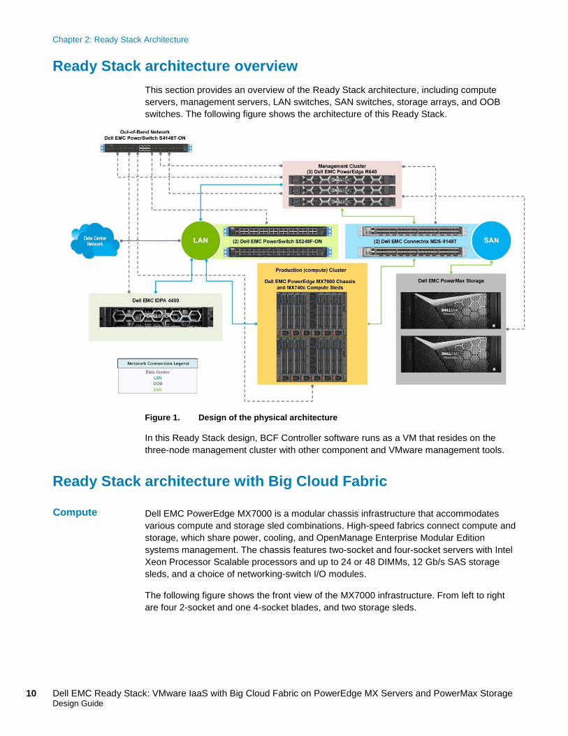
Ready Stack architecture overview This section provides an overview of the Ready Stack architecture, including compute servers, management servers, LAN switches, SAN switches, storage arrays, and OOB switches. The following figure shows the architecture of this Ready Stack.
Figure 1. Design of the physical architecture
In this Ready Stack design, BCF Controller software runs as a VM that resides on the three-node management cluster with other component and VMware management tools.
Ready Stack architecture with Big Cloud Fabric Dell EMC PowerEdge MX7000 is a modular chassis infrastructure that accommodates various compute and storage sled combinations. High-speed fabrics connect compute and storage, which share power, cooling, and OpenManage Enterprise Modular Edition systems management. The chassis features two-socket and four-socket servers with Intel Xeon Processor Scalable processors and up to 24 or 48 DIMMs, 12 Gb/s SAS storage sleds, and a choice of networking-switch I/O modules.
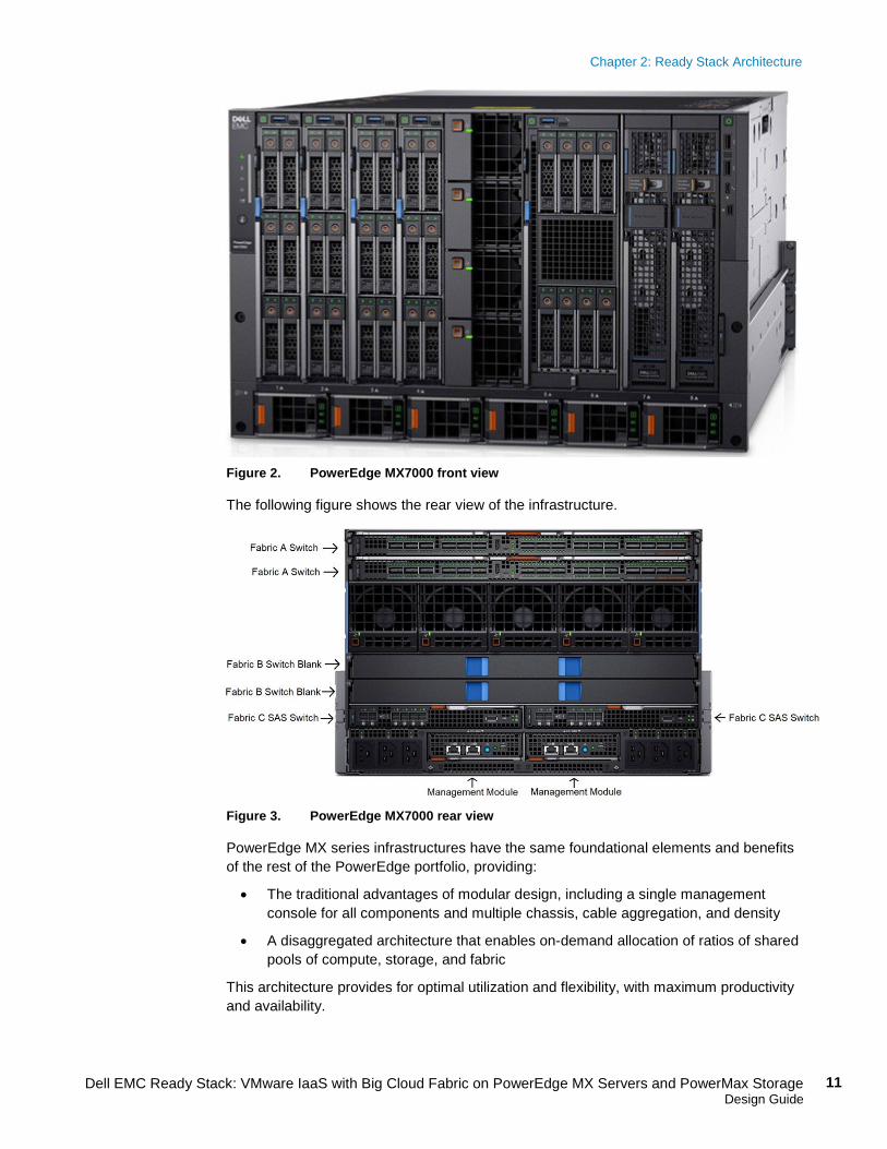
The following figure shows the front view of the MX7000 infrastructure. From left to right are four 2-socket and one 4-socket blades, and two storage sleds.
Compute
Chapter 2: Ready Stack Architecture
11 Dell EMC Ready Stack: VMware IaaS with Big Cloud Fabric on PowerEdge MX Servers and PowerMax Storage Design Guide
Figure 2. PowerEdge MX7000 front view
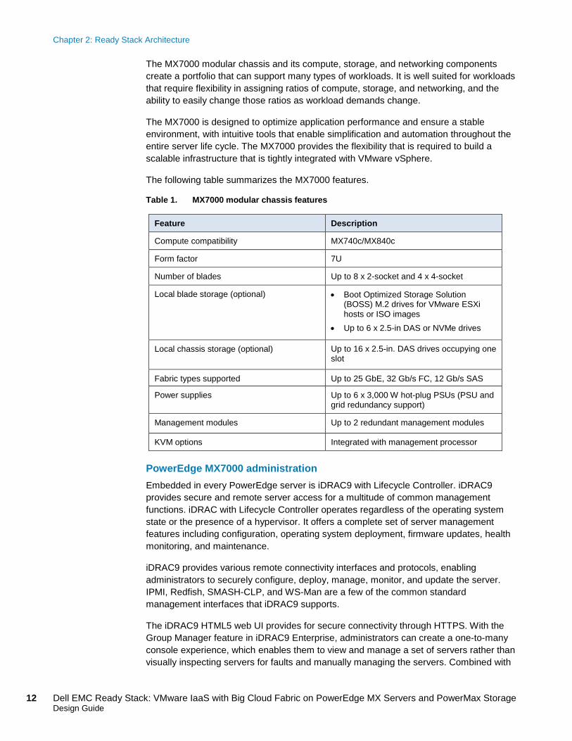
The following figure shows the rear view of the infrastructure.
Figure 3. PowerEdge MX7000 rear view
PowerEdge MX series infrastructures have the same foundational elements and benefits of the rest of the PowerEdge portfolio, providing:
• The traditional advantages of modular design, including a single management console for all components and multiple chassis, cable aggregation, and density
• A disaggregated architecture that enables on-demand allocation of ratios of shared pools of compute, storage, and fabric
This architecture provides for optimal utilization and flexibility, with maximum productivity and availability.
Chapter 2: Ready Stack Architecture
12 Dell EMC Ready Stack: VMware IaaS with Big Cloud Fabric on PowerEdge MX Servers and PowerMax Storage Design Guide
The MX7000 modular chassis and its compute, storage, and networking components create a portfolio that can support many types of workloads. It is well suited for workloads that require flexibility in assigning ratios of compute, storage, and networking, and the ability to easily change those ratios as workload demands change.
The MX7000 is designed to optimize application performance and ensure a stable environment, with intuitive tools that enable simplification and automation throughout the entire server life cycle. The MX7000 provides the flexibility that is required to build a scalable infrastructure that is tightly integrated with VMware vSphere.
The following table summarizes the MX7000 features.
Table 1. MX7000 modular chassis features
Feature Description
Compute compatibility MX740c/MX840c
Form factor 7U
Number of blades Up to 8 x 2-socket and 4 x 4-socket
Local blade storage (optional) • Boot Optimized Storage Solution (BOSS) M.2 drives for VMware ESXi hosts or ISO images
• Up to 6 x 2.5-in DAS or NVMe drives
Local chassis storage (optional)
Up to 16 x 2.5-in. DAS drives occupying one slot
Fabric types supported Up to 25 GbE, 32 Gb/s FC, 12 Gb/s SAS
Power supplies Up to 6 x 3,000 W hot-plug PSUs (PSU and grid redundancy support)
Management modules
Up to 2 redundant management modules
KVM options Integrated with management processor
PowerEdge MX7000 administration Embedded in every PowerEdge server is iDRAC9 with Lifecycle Controller. iDRAC9 provides secure and remote server access for a multitude of common management functions. iDRAC with Lifecycle Controller operates regardless of the operating system state or the presence of a hypervisor. It offers a complete set of server management features including configuration, operating system deployment, firmware updates, health monitoring, and maintenance.
iDRAC9 provides various remote connectivity interfaces and protocols, enabling administrators to securely configure, deploy, manage, monitor, and update the server. IPMI, Redfish, SMASH-CLP, and WS-Man are a few of the common standard management interfaces that iDRAC9 supports.
The iDRAC9 HTML5 web UI provides for secure connectivity through HTTPS. With the Group Manager feature in iDRAC9 Enterprise, administrators can create a one-to-many console experience, which enables them to view and manage a set of servers rather than visually inspecting servers for faults and manually managing the servers. Combined with
Chapter 2: Ready Stack Architecture
13 Dell EMC Ready Stack: VMware IaaS with Big Cloud Fabric on PowerEdge MX Servers and PowerMax Storage Design Guide
OpenManage Enterprise Modular Edition, iDRAC9 enables multichassis management in a one-to-many interface.
Network design is a fundamental aspect of the Ready Stack architecture and consists of these functional groups:
• OOB network
• LAN
• SAN Key building blocks The primary building block of the OOB network is the Dell EMC PowerSwitch S4148T-ON switch, which provides 48 ports of 1/10 GbE and multiple uplink port options (10/25/40/50/100 GbE).
The key building block of the LAN is the Dell EMC S5248-ON switch. The switch provides up to 128 ports of 10/25 GbE, 32 ports of 40 GbE, 64 ports of 50 GbE, and 32 ports of 100 GbE. Some port configurations require breakout cables. Using two edge S5248F-ON switches provides redundancy. Integrated NICs directly connect the management hosts, which are rackmount servers, to the edge switches.
The platform and compute hosts, which are blade servers that are installed in the MX7000, are a different case. Inside the MX7000, a unified connection carries both LAN and SAN traffic, which must be separated before leaving the MX7000 chassis. The separation occurs in the Dell EMC MX9116n Fabric Switching Engine (FSE), which is installed in the back of the MX7000 chassis. The FSE connects to both the LAN (at the edge switch) and the SAN. Two MX9116n FSEs, one per MX7000 chassis, provide redundancy in a two-chassis configuration. Also, the Ready Stack includes PowerEdge MX7116n Fabric Expansion Modules (FEMs)—one per MX7000 chassis in a two-chassis configuration—to provide blade-server connection redundancy.
The key building block of the SAN is the Dell EMC MDS Series FC switch. The SAN can be configured as a core-edge or edge-core-edge design, depending on requirements. For the models used in our Ready Stack configurations, see Design configurations and specifications.
Big Cloud Fabric BCF from Big Switch Networks brings hyperscale data center design principles to enterprise data centers. BCF is powered by spine and leaf fabric architecture that provides physical network automation, visibility, and troubleshooting for VMware environments.
BCF provides application agility due to automation, operational simplification due to SDN, and significant cost reduction due to hardware/software disaggregation that is enabled by Dell EMC Open Networking switches.
Combined with the high-performing Open Networking switches, BCF provides network automation for multiple VMware products. BCF delivers new visibility and troubleshooting capabilities for both VMware and network administrators, with the aid of the BCF plug-in for vSphere Web Client and VMware vRealize Log Insight.
Networking
Chapter 2: Ready Stack Architecture
14 Dell EMC Ready Stack: VMware IaaS with Big Cloud Fabric on PowerEdge MX Servers and PowerMax Storage Design Guide
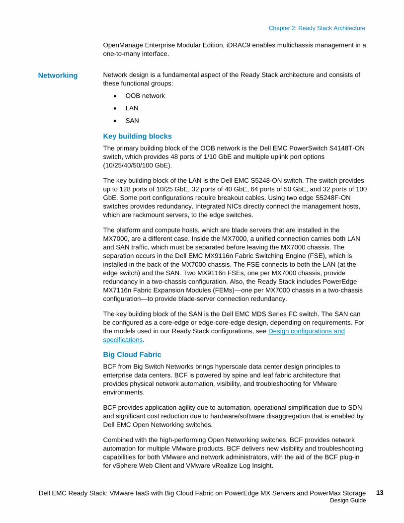
BCF lets you manage the network infrastructure as one big virtual switch compared with traditional box-by-box management, as shown in the following figure. Having one logical switch simplifies and accelerates the administration and management of the networking infrastructure.
Figure 4. One logical switch
The Dell EMC PowerMax family of storage systems provides simplicity, modern design, and flexible deployments. PowerMax systems implement an integrated architecture for block, file, and VMware Virtual Volumes, with concurrent support for native NAS, iSCSI, and FC protocols. The PowerMax systems support file and block environments, point-in-time snapshots, thin clones, synchronous and asynchronous replication, integrated encryption, tiering to the cloud, and deep ecosystem integration with VMware, Microsoft, and OpenStack.
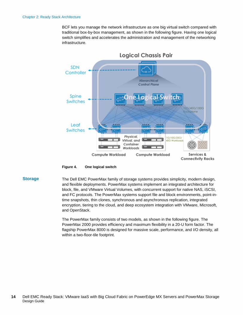
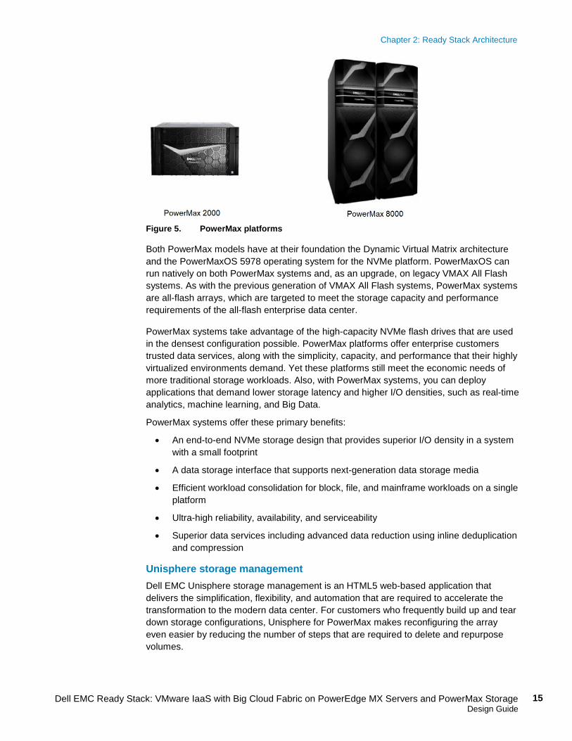
The PowerMax family consists of two models, as shown in the following figure. The PowerMax 2000 provides efficiency and maximum flexibility in a 20-U form factor. The flagship PowerMax 8000 is designed for massive scale, performance, and I/O density, all within a two-floor-tile footprint.
Storage
Chapter 2: Ready Stack Architecture
15 Dell EMC Ready Stack: VMware IaaS with Big Cloud Fabric on PowerEdge MX Servers and PowerMax Storage Design Guide
Figure 5. PowerMax platforms
Both PowerMax models have at their foundation the Dynamic Virtual Matrix architecture and the PowerMaxOS 5978 operating system for the NVMe platform. PowerMaxOS can run natively on both PowerMax systems and, as an upgrade, on legacy VMAX All Flash systems. As with the previous generation of VMAX All Flash systems, PowerMax systems are all-flash arrays, which are targeted to meet the storage capacity and performance requirements of the all-flash enterprise data center.
PowerMax systems take advantage of the high-capacity NVMe flash drives that are used in the densest configuration possible. PowerMax platforms offer enterprise customers trusted data services, along with the simplicity, capacity, and performance that their highly virtualized environments demand. Yet these platforms still meet the economic needs of more traditional storage workloads. Also, with PowerMax systems, you can deploy applications that demand lower storage latency and higher I/O densities, such as real-time analytics, machine learning, and Big Data.
PowerMax systems offer these primary benefits:
• An end-to-end NVMe storage design that provides superior I/O density in a system with a small footprint
• A data storage interface that supports next-generation data storage media
• Efficient workload consolidation for block, file, and mainframe workloads on a single platform
• Ultra-high reliability, availability, and serviceability
• Superior data services including advanced data reduction using inline deduplication and compression
Unisphere storage management Dell EMC Unisphere storage management is an HTML5 web-based application that delivers the simplification, flexibility, and automation that are required to accelerate the transformation to the modern data center. For customers who frequently build up and tear down storage configurations, Unisphere for PowerMax makes reconfiguring the array even easier by reducing the number of steps that are required to delete and repurpose volumes.
Chapter 2: Ready Stack Architecture
16 Dell EMC Ready Stack: VMware IaaS with Big Cloud Fabric on PowerEdge MX Servers and PowerMax Storage Design Guide
VMware integration PowerMax systems deliver deep integration with all the VMware vSphere core storage-enablement primitives. vSphere Storage APIs – Array Integration (VAAI), the core VMware API for storage offload, significantly increases the performance of the vSphere cluster. PowerMax systems support all VAAI primitives—XCOPY, UNMAP, WRITE SAME, and ATS Lock Extents. The systems also support VMware Virtual Volumes and vSphere APIs for Storage Awareness (VASA) 2.0 for next-generation VMware environments.
To enable orchestrated disaster recovery failover, PowerMax systems integrate with VMware Site Recovery Manager and vSphere Metro Storage Cluster (vMSC) with Dell EMC Symmetrix Remote Data Facility (SRDF) software. For heterogeneous target replication in virtualized environments and for VM-specific replication, PowerMax systems integrate with Dell EMC RecoverPoint and RecoverPoint for Virtual Machines, respectively.
PowerMax systems provide additional integration points, beyond the core VMware integration points, to ensure a complete integrated user experience that is familiar to the VMware administrator. Dell EMC VSI plugs into vSphere Web Client, enabling administrators to directly provision PowerMax storage, visualize the infrastructure, manage local replication, schedule UNMAP operations, and more. The Dell EMC Storage Analytics (ESA) plug-in provides integration with VMware vRealize Operations Manager to provide a complete end-to-end, in-context view of systems and storage health. Further, the Dell EMC VMAX and PowerMax Content Pack for vRealize Log Insight provides dashboards, alerts, and queries to sort and intelligently present PowerMax log information directly from vCenter. All PowerMax integrations for VMware environments are available at no additional cost.
This Ready Stack design uses a three-server external management cluster and, internal to the MX7000 chassis, a platform management cluster. This design follows the VMware Validated Design (VVD) Standard SDDC and provides maximum security, resource isolation, and scalability.
Management cluster In this Ready Stack design, the management cluster consists of three R640 rack servers. Having a separate management cluster of hosts, rather than a single host, ensures that management components have dedicated resources that are isolated from the production compute environment. Having a separate management cluster also provides for independent scaling of compute resources between management and production workloads. This separation makes it easier to determine the management components and their related infrastructure, reduces resource contention, and provides physical security and process boundaries.
The management cluster is configured to support a single host failure, commonly referred to as N+1. Adding management components beyond those that are specified might require additional hosts. The BCF Controller is a VM that is hosted within the management cluster. The version of vCenter running in this cluster also includes the BCF plug-in for vSphere Web Client.
Management
Chapter 2: Ready Stack Architecture
17 Dell EMC Ready Stack: VMware IaaS with Big Cloud Fabric on PowerEdge MX Servers and PowerMax Storage Design Guide
Production cluster The production (compute) cluster resides on blades in the PowerEdge MX7000 chassis and contains the IaaS components that are described in Infrastructure as a Service. The platform management hosts provide the automation and content catalog resources that are needed to support an IaaS production environment. This cluster is separate from the management cluster to ensure the performance, scalability, and security of the management and production clusters.
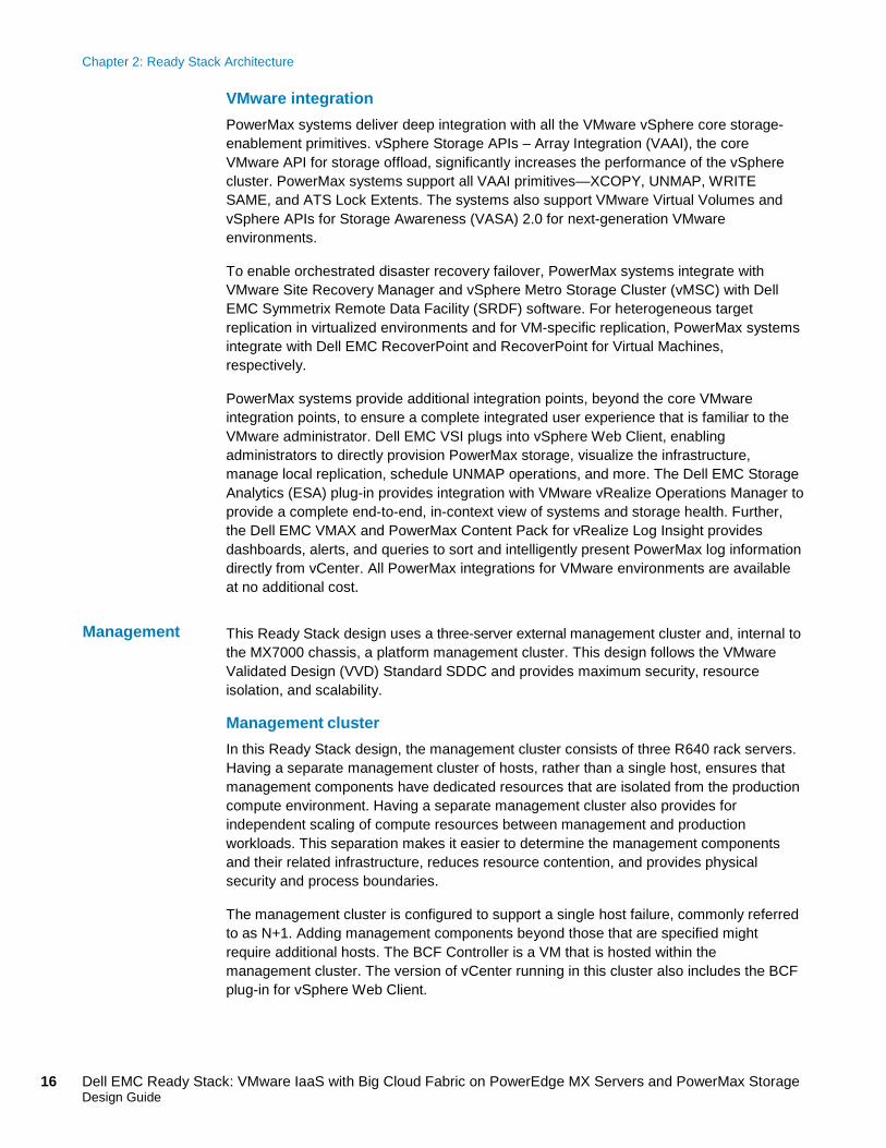
Separating the management and production clusters from one another also achieves a greater level of resiliency. When designing larger environments that use multiple MX7000 chassis, disaggregate the production cluster and spread it across multiple chassis and racks, as shown in the following figure:
Figure 6. Platform management on multiple MX7000 chassis
Chapter 2: Ready Stack Architecture
18 Dell EMC Ready Stack: VMware IaaS with Big Cloud Fabric on PowerEdge MX Servers and PowerMax Storage Design Guide
This disaggregation improves the fault tolerance of the cluster by removing potential points of failure. You can apply this method to other clusters as well to improve their resiliency.
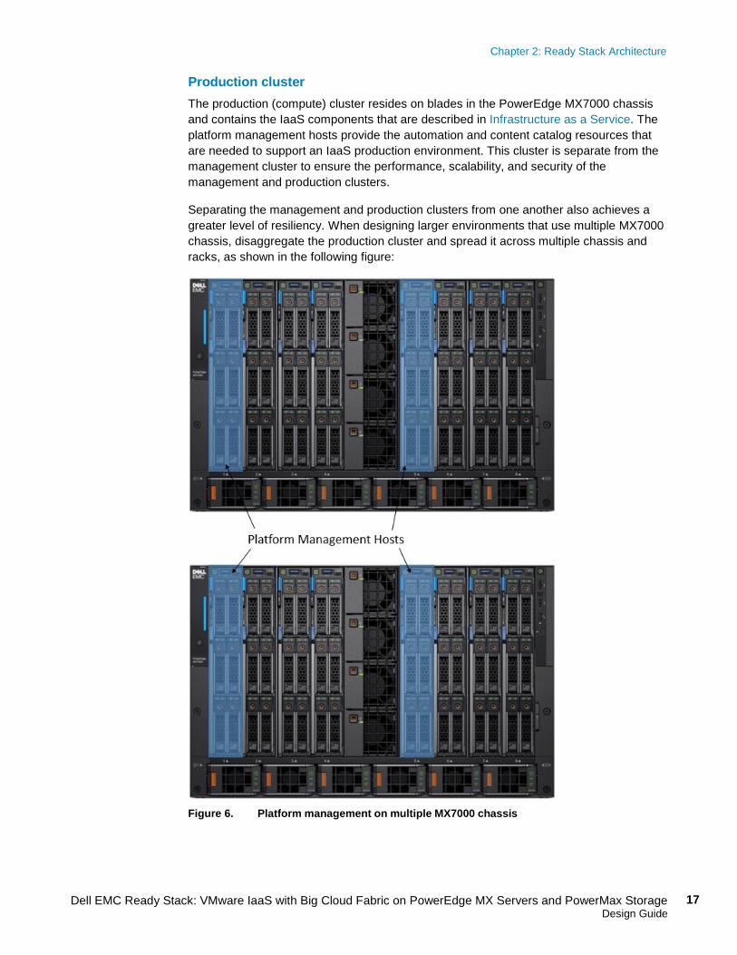
Network management with BCF Using the BCF Controller to perform configuration, automation, and most troubleshooting tasks dramatically decreases the number of management consoles that are required to provision new physical capacity or new logical applications. For example, in a 16-rack pod with dual leaf switches and two spine switches, a traditional network design would have 34 management consoles. The BCF design has only one—the controller console—to perform the same functions. The result is massive time savings, reduced error rates, and simpler automation designs.
As shown in the following figure, BCF Controller provides a single view for assessing the overall network status:
Figure 7. BCF UI dashboard page
Chapter 2: Ready Stack Architecture
19 Dell EMC Ready Stack: VMware IaaS with Big Cloud Fabric on PowerEdge MX Servers and PowerMax Storage Design Guide
In traditional network administration, the operational workflows are mostly manual (sometimes scripted, but the scripts must be maintained), resulting in loss of agility. The BCF architecture has integrated network automation. Rapid network upgrades are up to 20 times faster than legacy networks, resulting in lower network downtime, higher agility, and significant savings in operating expenses.
BCF integration with VMware Integrating BCF with the VMware SDDC provides:
• Physical network intelligence through a “one logical switch” operational model, deep fabric-wide visibility, and easy-to-configure service chaining
• Physical network agility through network automation, zero-touch fabric, controller-coordinated upgrading, and rapid VM-to-VM troubleshooting
• Deployment flexibility through Dell EMC Open Networking hardware and scale-as-you-grow options for all application workloads (physical, VM, and container)
BCF integration with VMware vSphere, NSX, vSAN, Integrated OpenStack, and vRealize Log Insight provides network automation and visibility. Network administrators gain visibility into the virtualization environment through the BCF Controller and can use the BCF plug-in for vSphere Web Client to provide fabric visibility to the VMware administrator.
This section briefly describes the IaaS components of this Ready Stack.
VMware IaaS VMware IaaS provides virtualized computing resources by separating applications and their resource demands from the underlying infrastructure resources on which they rely. VVD for SDDC extends the typical IaaS solution to include operations management, business continuity, and security.
The combination of compute, storage, and networking hardware in this Ready Stack provides an ideal platform on which to configure IaaS. For more information, see Validated Designs on the VMware website.
Enterprise Storage Analytics Dell EMC ESA for vRealize Operations enables customers to optimize performance and diagnose issues across their physical storage and VMs. Dell EMC ESA for vRealize Operations:
• Collects analytical data from Dell EMC resources and provides actionable performance analysis
• Proactively delivers a single, end-to-end view of virtualized infrastructures, from servers to storage
• Provides increased visibility, metrics, and a rich collection of storage analytics
vRealize Log Insight Through log analytics, aggregation, and search, vRealize Log Insight delivers automated log management that provides operational intelligence and visibility for enabling service levels and increasing operational efficiency.
Infrastructure as a service
Chapter 2: Ready Stack Architecture
20 Dell EMC Ready Stack: VMware IaaS with Big Cloud Fabric on PowerEdge MX Servers and PowerMax Storage Design Guide
VMAX and PowerMax Content Pack The Dell EMC VMAX and PowerMax Content Pack, when integrated with VMware vRealize Log Insight, provides dashboards and user-defined fields for VMAX and PowerMax storage. These tools enable administrators to conduct problem analysis and analytics on their arrays.
Chapter 3: Configurations and Specifications
21 Dell EMC Ready Stack: VMware IaaS with Big Cloud Fabric on PowerEdge MX Servers and PowerMax Storage Design Guide
Chapter 3 Configurations and Specifications
This chapter presents the following topics:
Recommended platforms and components ..................................................... 22
Ready Stack scaling ......................................................................................... 23
Design configurations and specifications ....................................................... 24
Chapter 3: Configurations and Specifications
22 Dell EMC Ready Stack: VMware IaaS with Big Cloud Fabric on PowerEdge MX Servers and PowerMax Storage Design Guide
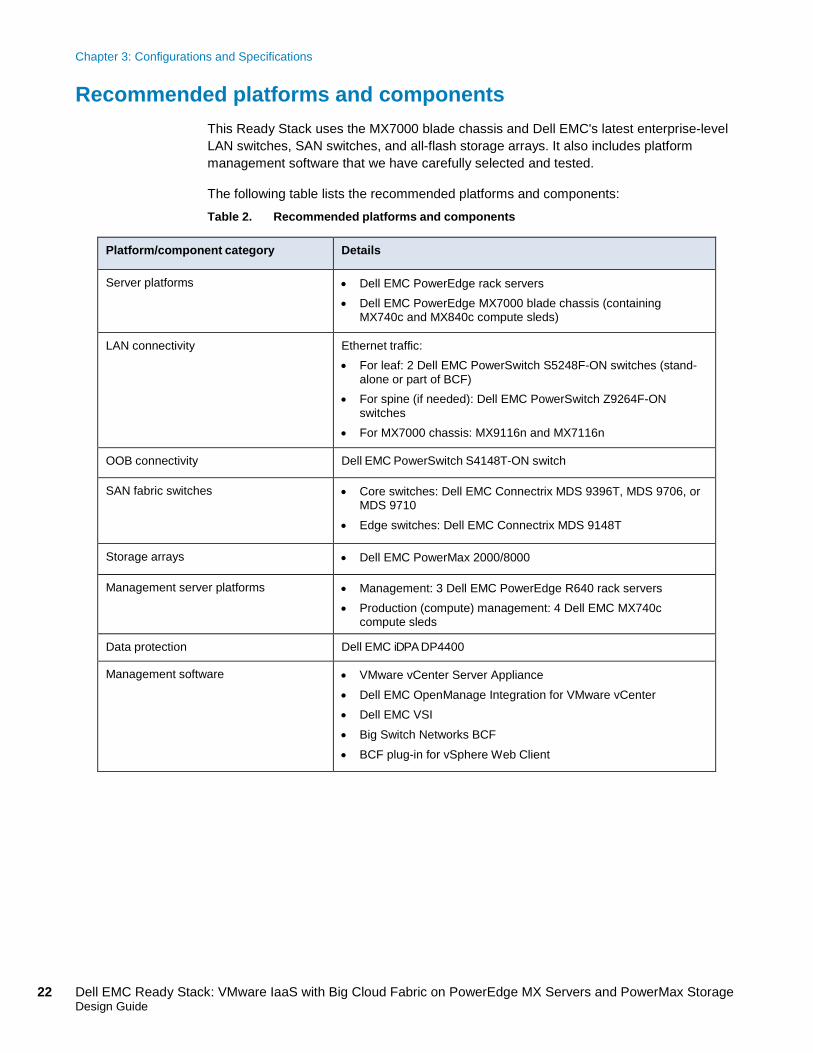
Recommended platforms and components This Ready Stack uses the MX7000 blade chassis and Dell EMC's latest enterprise-level LAN switches, SAN switches, and all-flash storage arrays. It also includes platform management software that we have carefully selected and tested.
The following table lists the recommended platforms and components: Table 2. Recommended platforms and components
Platform/component category Details
Server platforms • Dell EMC PowerEdge rack servers • Dell EMC PowerEdge MX7000 blade chassis (containing
MX740c and MX840c compute sleds)
LAN connectivity Ethernet traffic: • For leaf: 2 Dell EMC PowerSwitch S5248F-ON switches (stand-
alone or part of BCF) • For spine (if needed): Dell EMC PowerSwitch Z9264F-ON
switches • For MX7000 chassis: MX9116n and MX7116n
OOB connectivity Dell EMC PowerSwitch S4148T-ON switch
SAN fabric switches • Core switches: Dell EMC Connectrix MDS 9396T, MDS 9706, or MDS 9710
• Edge switches: Dell EMC Connectrix MDS 9148T
Storage arrays • Dell EMC PowerMax 2000/8000
Management server platforms • Management: 3 Dell EMC PowerEdge R640 rack servers • Production (compute) management: 4 Dell EMC MX740c
compute sleds
Data protection Dell EMC iDPA DP4400
Management software • VMware vCenter Server Appliance • Dell EMC OpenManage Integration for VMware vCenter • Dell EMC VSI • Big Switch Networks BCF • BCF plug-in for vSphere Web Client
Chapter 3: Configurations and Specifications
23 Dell EMC Ready Stack: VMware IaaS with Big Cloud Fabric on PowerEdge MX Servers and PowerMax Storage Design Guide
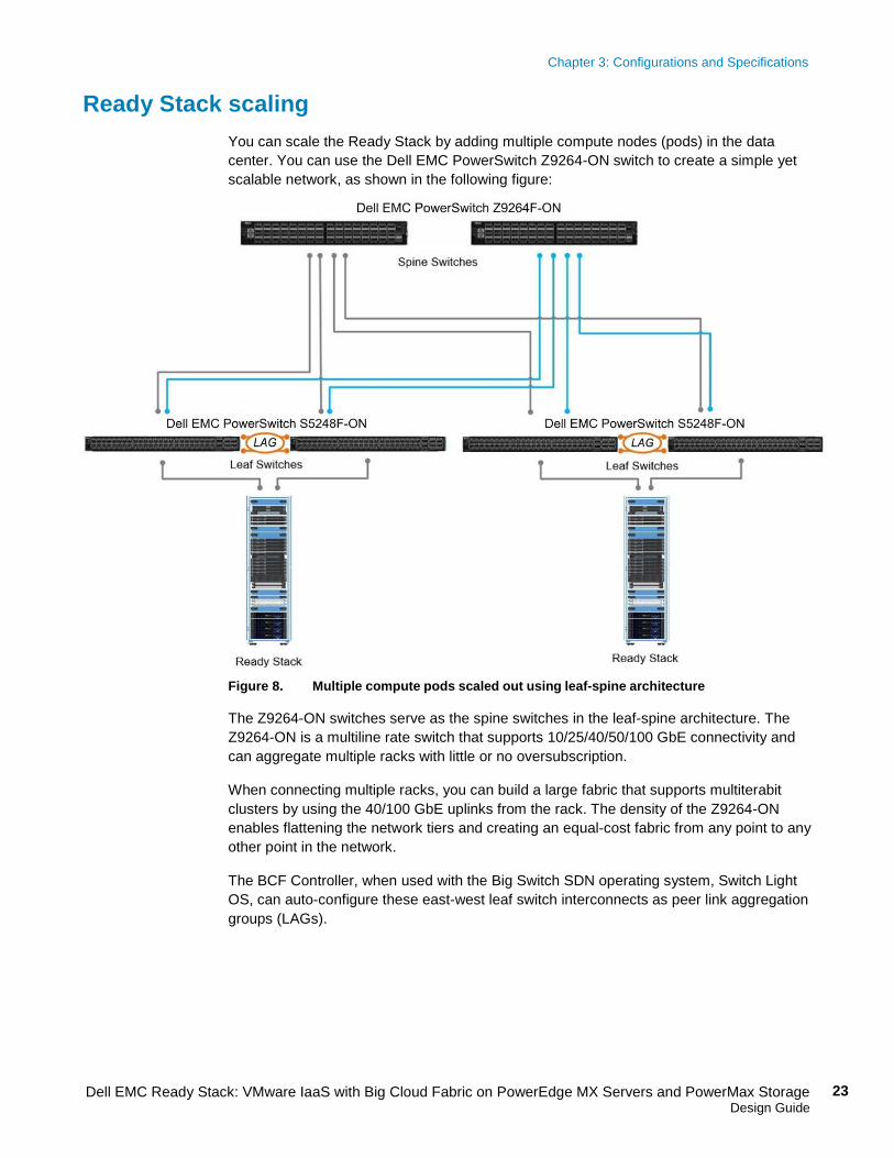
Ready Stack scaling You can scale the Ready Stack by adding multiple compute nodes (pods) in the data center. You can use the Dell EMC PowerSwitch Z9264-ON switch to create a simple yet scalable network, as shown in the following figure:
Figure 8. Multiple compute pods scaled out using leaf-spine architecture
The Z9264-ON switches serve as the spine switches in the leaf-spine architecture. The Z9264-ON is a multiline rate switch that supports 10/25/40/50/100 GbE connectivity and can aggregate multiple racks with little or no oversubscription.
When connecting multiple racks, you can build a large fabric that supports multiterabit clusters by using the 40/100 GbE uplinks from the rack. The density of the Z9264-ON enables flattening the network tiers and creating an equal-cost fabric from any point to any other point in the network.
The BCF Controller, when used with the Big Switch SDN operating system, Switch Light OS, can auto-configure these east-west leaf switch interconnects as peer link aggregation groups (LAGs).
Chapter 3: Configurations and Specifications
24 Dell EMC Ready Stack: VMware IaaS with Big Cloud Fabric on PowerEdge MX Servers and PowerMax Storage Design Guide
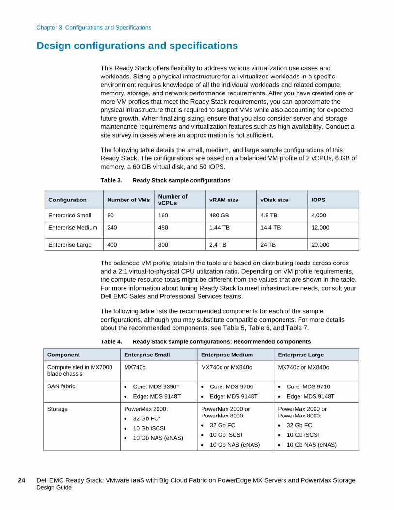
Design configurations and specifications This Ready Stack offers flexibility to address various virtualization use cases and workloads. Sizing a physical infrastructure for all virtualized workloads in a specific environment requires knowledge of all the individual workloads and related compute, memory, storage, and network performance requirements. After you have created one or more VM profiles that meet the Ready Stack requirements, you can approximate the physical infrastructure that is required to support VMs while also accounting for expected future growth. When finalizing sizing, ensure that you also consider server and storage maintenance requirements and virtualization features such as high availability. Conduct a site survey in cases where an approximation is not sufficient.
The following table details the small, medium, and large sample configurations of this Ready Stack. The configurations are based on a balanced VM profile of 2 vCPUs, 6 GB of memory, a 60 GB virtual disk, and 50 IOPS.
Table 3. Ready Stack sample configurations
Configuration Number of VMs Number of vCPUs vRAM size vDisk size IOPS
Enterprise Small 80 160 480 GB 4.8 TB 4,000
Enterprise Medium 240 480 1.44 TB 14.4 TB 12,000
Enterprise Large 400 800 2.4 TB 24 TB 20,000
The balanced VM profile totals in the table are based on distributing loads across cores and a 2:1 virtual-to-physical CPU utilization ratio. Depending on VM profile requirements, the compute resource totals might be different from the values that are shown in the table. For more information about tuning Ready Stack to meet infrastructure needs, consult your Dell EMC Sales and Professional Services teams.
The following table lists the recommended components for each of the sample configurations, although you may substitute compatible components. For more details about the recommended components, see Table 5, Table 6, and Table 7.
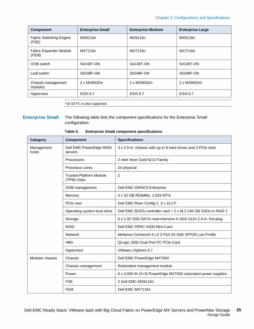
Table 4. Ready Stack sample configurations: Recommended components
Component Enterprise Small Enterprise Medium Enterprise Large
Compute sled in MX7000 blade chassis
MX740c MX740c or MX840c MX740c or MX840c
SAN fabric • Core: MDS 9396T • Edge: MDS 9148T
• Core: MDS 9706 • Edge: MDS 9148T
• Core: MDS 9710 • Edge: MDS 9148T
Storage PowerMax 2000: • 32 Gb FC* • 10 Gb iSCSI • 10 Gb NAS (eNAS)
PowerMax 2000 or PowerMax 8000: • 32 Gb FC • 10 Gb iSCSI • 10 Gb NAS (eNAS)
PowerMax 2000 or PowerMax 8000: • 32 Gb FC • 10 Gb iSCSI • 10 Gb NAS (eNAS)
Chapter 3: Configurations and Specifications
25 Dell EMC Ready Stack: VMware IaaS with Big Cloud Fabric on PowerEdge MX Servers and PowerMax Storage Design Guide
Component Enterprise Small Enterprise Medium Enterprise Large
Fabric Switching Engine (FSE)
MX9116n MX9116n MX9116n
Fabric Expander Module (FEM)
MX7116n MX7116n MX7116n
OOB switch S4148T-ON S4148T-ON S4148T-ON
Leaf switch S5248F-ON S5248F-ON S5248F-ON
Chassis management modules
2 x MX9002m 2 x MX9002m 2 x MX9002m
Hypervisor ESXi 6.7 ESXi 6.7 ESXi 6.7
*16 Gb FC is also supported.
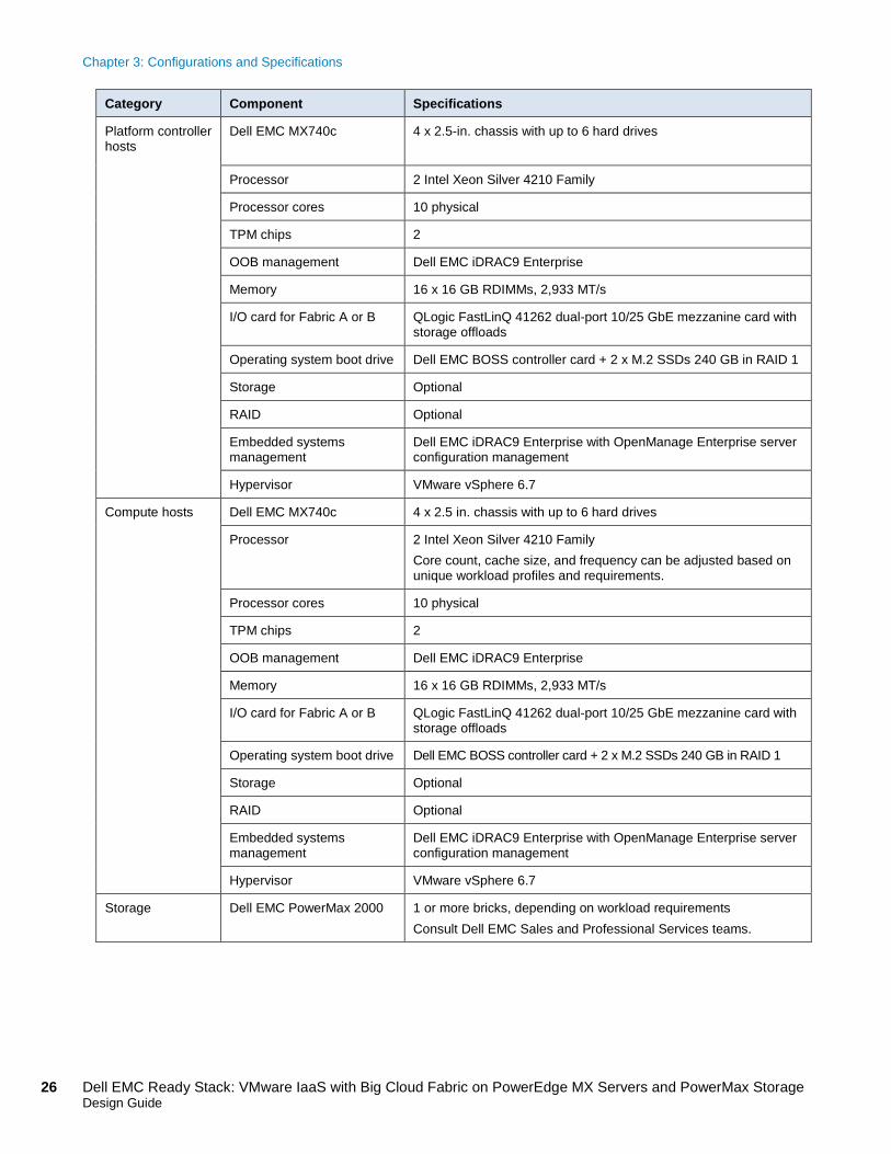
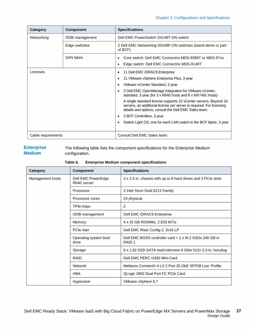
The following table lists the component specifications for the Enterprise Small configuration.
Table 5. Enterprise Small component specifications
Category Component Specifications
Management hosts
Dell EMC PowerEdge R640 servers
3 x 2.5-in. chassis with up to 8 hard drives and 3 PCIe slots
Processors 2 Intel Xeon Gold 6212 Family
Processor cores 24 physical
Trusted Platform Module (TPM) chips
2
OOB management Dell EMC iDRAC9 Enterprise
Memory 4 x 32 GB RDIMMs, 2,933 MT/s
PCIe riser Dell EMC Riser Config 2, 3 x 16 LP
Operating system boot drive Dell EMC BOSS controller card + 2 x M.2 240 GB SSDs in RAID 1
Storage 6 x 1.92 SSD SATA read-intensive 6 Gb/s 512n 2.5-in. hot-plug
RAID Dell EMC PERC H330 Mini-Card
Network Mellanox ConnectX-4 LX 2 Port 25 GbE SFP28 Low Profile
HBA QLogic 2692 Dual Port FC PCIe Card
Hypervisor VMware vSphere 6.7
Modular chassis Chassis Dell EMC PowerEdge MX7000
Chassis management Redundant management module
Power 6 x 3,000 W (3+3) PowerEdge MX7000 redundant power supplies
FSE 2 Dell EMC MX9116n
FEM Dell EMC MX7116n
Enterprise Small
Chapter 3: Configurations and Specifications
26 Dell EMC Ready Stack: VMware IaaS with Big Cloud Fabric on PowerEdge MX Servers and PowerMax Storage Design Guide
Category Component Specifications
Platform controller hosts
Dell EMC MX740c 4 x 2.5-in. chassis with up to 6 hard drives
Processor 2 Intel Xeon Silver 4210 Family
Processor cores 10 physical
TPM chips 2
OOB management Dell EMC iDRAC9 Enterprise
Memory 16 x 16 GB RDIMMs, 2,933 MT/s
I/O card for Fabric A or B QLogic FastLinQ 41262 dual-port 10/25 GbE mezzanine card with storage offloads
Operating system boot drive Dell EMC BOSS controller card + 2 x M.2 SSDs 240 GB in RAID 1
Storage Optional
RAID Optional
Embedded systems management
Dell EMC iDRAC9 Enterprise with OpenManage Enterprise server configuration management
Hypervisor VMware vSphere 6.7
Compute hosts Dell EMC MX740c 4 x 2.5 in. chassis with up to 6 hard drives
Processor 2 Intel Xeon Silver 4210 Family Core count, cache size, and frequency can be adjusted based on unique workload profiles and requirements.
Processor cores 10 physical
TPM chips 2
OOB management Dell EMC iDRAC9 Enterprise
Memory 16 x 16 GB RDIMMs, 2,933 MT/s
I/O card for Fabric A or B QLogic FastLinQ 41262 dual-port 10/25 GbE mezzanine card with storage offloads
Operating system boot drive Dell EMC BOSS controller card + 2 x M.2 SSDs 240 GB in RAID 1
Storage Optional
RAID Optional
Embedded systems management
Dell EMC iDRAC9 Enterprise with OpenManage Enterprise server configuration management
Hypervisor VMware vSphere 6.7
Storage Dell EMC PowerMax 2000 1 or more bricks, depending on workload requirements Consult Dell EMC Sales and Professional Services teams.
Chapter 3: Configurations and Specifications
27 Dell EMC Ready Stack: VMware IaaS with Big Cloud Fabric on PowerEdge MX Servers and PowerMax Storage Design Guide
Category Component Specifications
Networking OOB management Dell EMC PowerSwitch S4148T-ON switch
Edge switches 2 Dell EMC Networking S5248F-ON switches (stand-alone or part of BCF)
SAN fabric • Core switch: Dell EMC Connectrix MDS-9396T or MDS-97xx • Edge switch: Dell EMC Connectrix MDS-9148T
Licenses • 11 Dell EMC iDRAC9 Enterprise • 11 VMware vSphere Enterprise Plus, 3 year • VMware vCenter Standard, 3 year • 2 Dell EMC OpenManage Integration for VMware vCenter,
standard, 3 year (for 3 x R640 hosts and 8 x MX740c hosts) A single standard license supports 10 vCenter servers. Beyond 10 servers, an additional license per server is required. For licensing details and options, consult the Dell EMC Sales team.
• 2 BCF Controllers, 3 year • Switch Light OS, one for each LAN switch in the BCF fabric, 3 year
Cable requirements Consult Dell EMC Sales team.
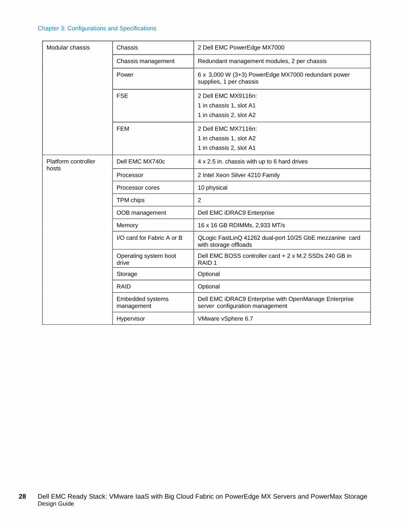
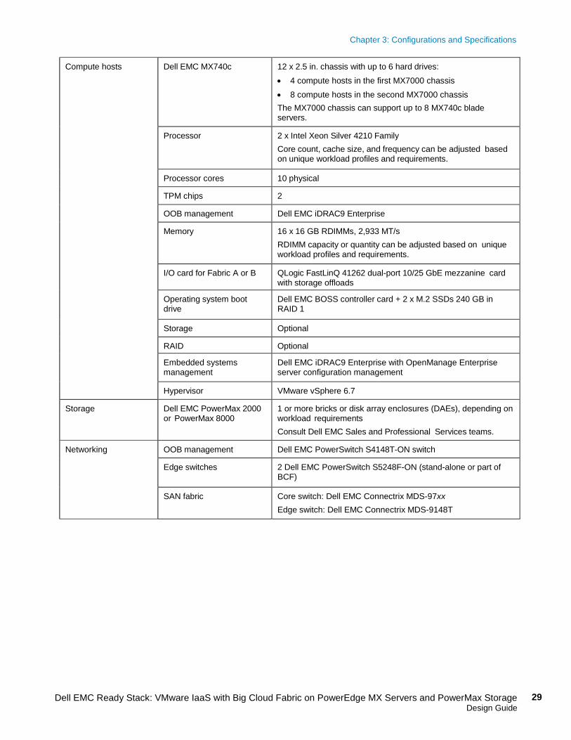
The following table lists the component specifications for the Enterprise Medium configuration.
Table 6. Enterprise Medium component specifications
Category Component Specifications
Management hosts Dell EMC PowerEdge R640 server
3 x 2.5 in. chassis with up to 8 hard drives and 3 PCIe slots
Processor 2 Intel Xeon Gold 6212 Family
Processor cores 24 physical
TPM chips 2
OOB management Dell EMC iDRAC9 Enterprise
Memory 4 x 32 GB RDIMMs, 2,933 MT/s
PCIe riser Dell EMC Riser Config 2, 3x16 LP
Operating system boot drive
Dell EMC BOSS controller card + 2 x M.2 SSDs 240 GB in RAID 1
Storage 6 x 1.92 SSD SATA read-intensive 6 Gb/s 512n 2.5-in. hot-plug
RAID Dell EMC PERC H330 Mini-Card
Network Mellanox ConnectX-4 LX 2 Port 25 GbE SFP28 Low Profile
HBA QLogic 2692 Dual Port FC PCIe Card
Hypervisor VMware vSphere 6.7
Enterprise Medium
Chapter 3: Configurations and Specifications
28 Dell EMC Ready Stack: VMware IaaS with Big Cloud Fabric on PowerEdge MX Servers and PowerMax Storage Design Guide
Modular chassis Chassis 2 Dell EMC PowerEdge MX7000
Chassis management Redundant management modules, 2 per chassis
Power 6 x 3,000 W (3+3) PowerEdge MX7000 redundant power supplies, 1 per chassis
FSE 2 Dell EMC MX9116n: 1 in chassis 1, slot A1 1 in chassis 2, slot A2
FEM 2 Dell EMC MX7116n: 1 in chassis 1, slot A2 1 in chassis 2, slot A1
Platform controller hosts
Dell EMC MX740c 4 x 2.5 in. chassis with up to 6 hard drives
Processor 2 Intel Xeon Silver 4210 Family
Processor cores 10 physical
TPM chips 2
OOB management Dell EMC iDRAC9 Enterprise
Memory 16 x 16 GB RDIMMs, 2,933 MT/s
I/O card for Fabric A or B QLogic FastLinQ 41262 dual-port 10/25 GbE mezzanine card with storage offloads
Operating system boot drive
Dell EMC BOSS controller card + 2 x M.2 SSDs 240 GB in RAID 1
Storage Optional
RAID Optional
Embedded systems management
Dell EMC iDRAC9 Enterprise with OpenManage Enterprise server configuration management
Hypervisor VMware vSphere 6.7
Chapter 3: Configurations and Specifications
29 Dell EMC Ready Stack: VMware IaaS with Big Cloud Fabric on PowerEdge MX Servers and PowerMax Storage Design Guide
Compute hosts Dell EMC MX740c 12 x 2.5 in. chassis with up to 6 hard drives: • 4 compute hosts in the first MX7000 chassis • 8 compute hosts in the second MX7000 chassis The MX7000 chassis can support up to 8 MX740c blade servers.
Processor 2 x Intel Xeon Silver 4210 Family Core count, cache size, and frequency can be adjusted based on unique workload profiles and requirements.
Processor cores 10 physical
TPM chips 2
OOB management Dell EMC iDRAC9 Enterprise
Memory 16 x 16 GB RDIMMs, 2,933 MT/s RDIMM capacity or quantity can be adjusted based on unique workload profiles and requirements.
I/O card for Fabric A or B QLogic FastLinQ 41262 dual-port 10/25 GbE mezzanine card with storage offloads
Operating system boot drive
Dell EMC BOSS controller card + 2 x M.2 SSDs 240 GB in RAID 1
Storage Optional
RAID Optional
Embedded systems management
Dell EMC iDRAC9 Enterprise with OpenManage Enterprise server configuration management
Hypervisor VMware vSphere 6.7
Storage Dell EMC PowerMax 2000 or PowerMax 8000
1 or more bricks or disk array enclosures (DAEs), depending on workload requirements Consult Dell EMC Sales and Professional Services teams.
Networking OOB management Dell EMC PowerSwitch S4148T-ON switch
Edge switches 2 Dell EMC PowerSwitch S5248F-ON (stand-alone or part of BCF)
SAN fabric Core switch: Dell EMC Connectrix MDS-97xx Edge switch: Dell EMC Connectrix MDS-9148T
Chapter 3: Configurations and Specifications
30 Dell EMC Ready Stack: VMware IaaS with Big Cloud Fabric on PowerEdge MX Servers and PowerMax Storage Design Guide
Licenses • 19 Dell EMC iDRAC9 Enterprise • 19 VMware vSphere Enterprise Plus, 3 year • 2 VMware vCenter Standard, 3 year (one for the vCenter
Server Appliance management hosts; one for the vCenter Server Appliance platform and compute hosts)
• 2 Dell EMC OpenManage Integration for VMware vCenter, standard, 3 year (for 3 x R640 hosts and 16 x MX740c hosts) A single standard license supports 10 vCenter servers. Beyond 10 servers, an additional license per server is required. For licensing details and options, consult the Dell EMC Sales team.
• 2 BCF Controllers, 3 year • Switch Light OS—one for each LAN switch in the BCF
fabric, 3 year
Cable requirements Consult the Dell EMC Sales team.
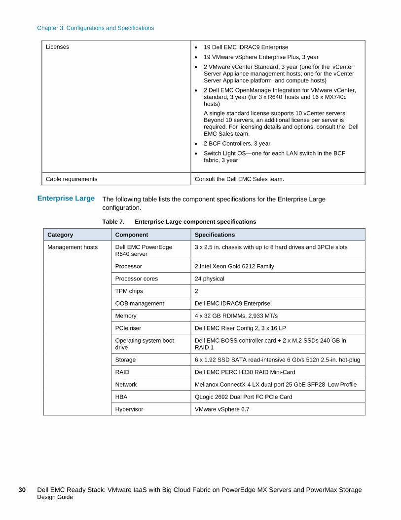
The following table lists the component specifications for the Enterprise Large configuration.
Table 7. Enterprise Large component specifications
Category Component Specifications
Management hosts Dell EMC PowerEdge R640 server
3 x 2.5 in. chassis with up to 8 hard drives and 3PCIe slots
Processor 2 Intel Xeon Gold 6212 Family
Processor cores 24 physical
TPM chips 2
OOB management Dell EMC iDRAC9 Enterprise
Memory 4 x 32 GB RDIMMs, 2,933 MT/s
PCIe riser Dell EMC Riser Config 2, 3 x 16 LP
Operating system boot drive
Dell EMC BOSS controller card + 2 x M.2 SSDs 240 GB in RAID 1
Storage 6 x 1.92 SSD SATA read-intensive 6 Gb/s 512n 2.5-in. hot-plug
RAID Dell EMC PERC H330 RAID Mini-Card
Network Mellanox ConnectX-4 LX dual-port 25 GbE SFP28 Low Profile
HBA QLogic 2692 Dual Port FC PCIe Card
Hypervisor VMware vSphere 6.7
Enterprise Large
Chapter 3: Configurations and Specifications
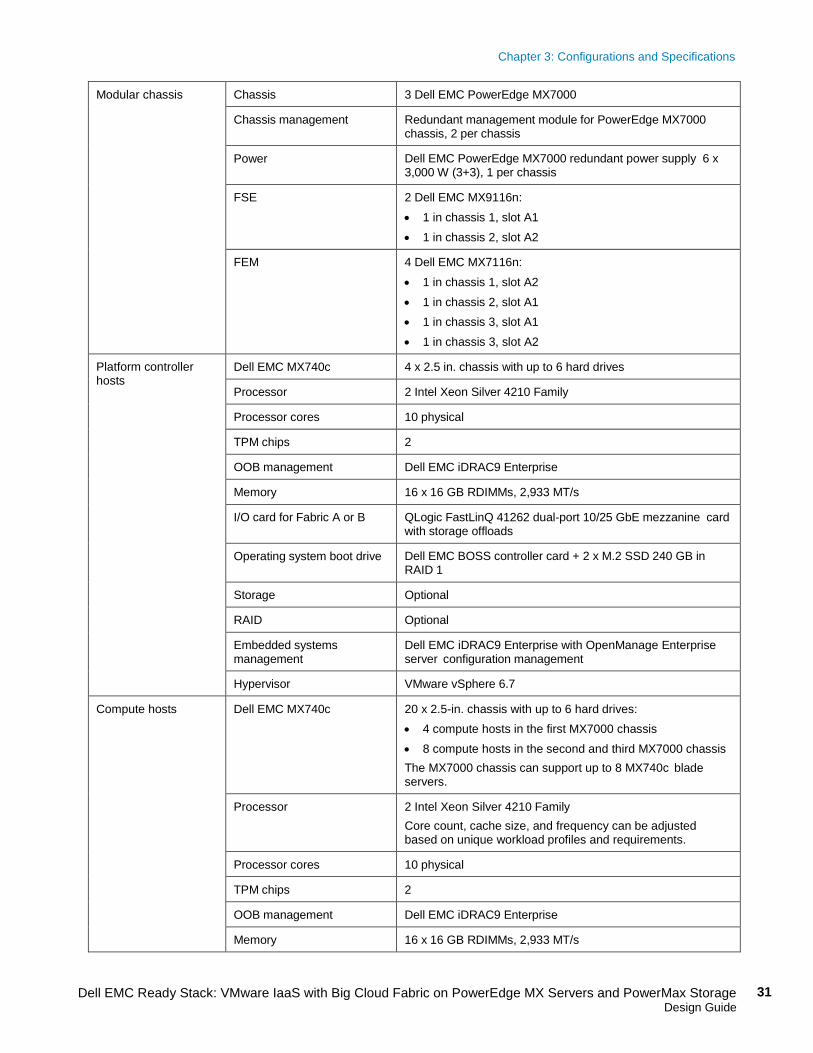
31 Dell EMC Ready Stack: VMware IaaS with Big Cloud Fabric on PowerEdge MX Servers and PowerMax Storage Design Guide
Modular chassis Chassis 3 Dell EMC PowerEdge MX7000
Chassis management Redundant management module for PowerEdge MX7000 chassis, 2 per chassis
Power Dell EMC PowerEdge MX7000 redundant power supply 6 x 3,000 W (3+3), 1 per chassis
FSE 2 Dell EMC MX9116n: • 1 in chassis 1, slot A1 • 1 in chassis 2, slot A2
FEM 4 Dell EMC MX7116n: • 1 in chassis 1, slot A2 • 1 in chassis 2, slot A1 • 1 in chassis 3, slot A1 • 1 in chassis 3, slot A2
Platform controller hosts
Dell EMC MX740c 4 x 2.5 in. chassis with up to 6 hard drives
Processor 2 Intel Xeon Silver 4210 Family
Processor cores 10 physical
TPM chips 2
OOB management Dell EMC iDRAC9 Enterprise
Memory 16 x 16 GB RDIMMs, 2,933 MT/s
I/O card for Fabric A or B QLogic FastLinQ 41262 dual-port 10/25 GbE mezzanine card with storage offloads
Operating system boot drive Dell EMC BOSS controller card + 2 x M.2 SSD 240 GB in RAID 1
Storage Optional
RAID Optional
Embedded systems management
Dell EMC iDRAC9 Enterprise with OpenManage Enterprise server configuration management
Hypervisor VMware vSphere 6.7
Compute hosts Dell EMC MX740c 20 x 2.5-in. chassis with up to 6 hard drives: • 4 compute hosts in the first MX7000 chassis • 8 compute hosts in the second and third MX7000 chassis The MX7000 chassis can support up to 8 MX740c blade servers.
Processor 2 Intel Xeon Silver 4210 Family Core count, cache size, and frequency can be adjusted based on unique workload profiles and requirements.
Processor cores 10 physical
TPM chips 2
OOB management Dell EMC iDRAC9 Enterprise
Memory 16 x 16 GB RDIMMs, 2,933 MT/s
Chapter 3: Configurations and Specifications
32 Dell EMC Ready Stack: VMware IaaS with Big Cloud Fabric on PowerEdge MX Servers and PowerMax Storage Design Guide
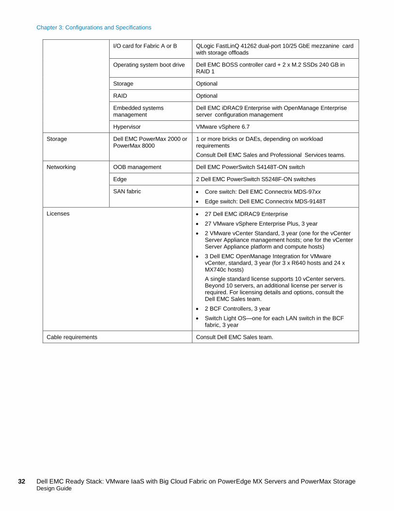
I/O card for Fabric A or B QLogic FastLinQ 41262 dual-port 10/25 GbE mezzanine card with storage offloads
Operating system boot drive Dell EMC BOSS controller card + 2 x M.2 SSDs 240 GB in RAID 1
Storage Optional
RAID Optional
Embedded systems management
Dell EMC iDRAC9 Enterprise with OpenManage Enterprise server configuration management
Hypervisor VMware vSphere 6.7
Storage Dell EMC PowerMax 2000 or PowerMax 8000
1 or more bricks or DAEs, depending on workload requirements Consult Dell EMC Sales and Professional Services teams.
Networking OOB management Dell EMC PowerSwitch S4148T-ON switch
Edge 2 Dell EMC PowerSwitch S5248F-ON switches
SAN fabric • Core switch: Dell EMC Connectrix MDS-97xx • Edge switch: Dell EMC Connectrix MDS-9148T
Licenses • 27 Dell EMC iDRAC9 Enterprise • 27 VMware vSphere Enterprise Plus, 3 year • 2 VMware vCenter Standard, 3 year (one for the vCenter
Server Appliance management hosts; one for the vCenter Server Appliance platform and compute hosts)
• 3 Dell EMC OpenManage Integration for VMware vCenter, standard, 3 year (for 3 x R640 hosts and 24 x MX740c hosts) A single standard license supports 10 vCenter servers. Beyond 10 servers, an additional license per server is required. For licensing details and options, consult the Dell EMC Sales team.
• 2 BCF Controllers, 3 year • Switch Light OS—one for each LAN switch in the BCF
fabric, 3 year
Cable requirements Consult Dell EMC Sales team.
Chapter 4: Ready Stack Design
33 Dell EMC Ready Stack: VMware IaaS with Big Cloud Fabric on PowerEdge MX Servers and PowerMax Storage Design Guide
Chapter 4 Ready Stack Design
This chapter presents the following topics:
Compute design ................................................................................................ 34
Network design ................................................................................................. 34
Storage design .................................................................................................. 37
Management design .......................................................................................... 43
Chapter 4: Ready Stack Design
34 Dell EMC Ready Stack: VMware IaaS with Big Cloud Fabric on PowerEdge MX Servers and PowerMax Storage Design Guide
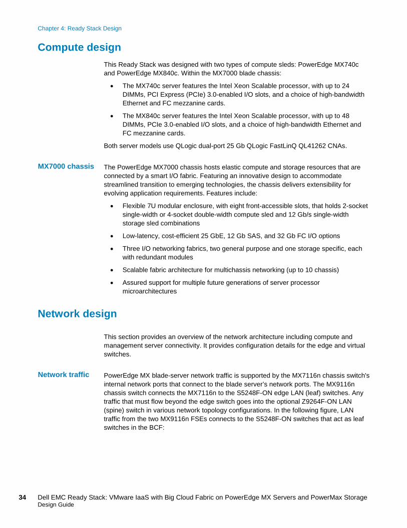
Compute design This Ready Stack was designed with two types of compute sleds: PowerEdge MX740c and PowerEdge MX840c. Within the MX7000 blade chassis:
• The MX740c server features the Intel Xeon Scalable processor, with up to 24 DIMMs, PCI Express (PCIe) 3.0-enabled I/O slots, and a choice of high-bandwidth Ethernet and FC mezzanine cards.
• The MX840c server features the Intel Xeon Scalable processor, with up to 48 DIMMs, PCIe 3.0-enabled I/O slots, and a choice of high-bandwidth Ethernet and FC mezzanine cards.
Both server models use QLogic dual-port 25 Gb QLogic FastLinQ QL41262 CNAs.
The PowerEdge MX7000 chassis hosts elastic compute and storage resources that are connected by a smart I/O fabric. Featuring an innovative design to accommodate streamlined transition to emerging technologies, the chassis delivers extensibility for evolving application requirements. Features include:
• Flexible 7U modular enclosure, with eight front-accessible slots, that holds 2-socket single-width or 4-socket double-width compute sled and 12 Gb/s single-width storage sled combinations
• Low-latency, cost-efficient 25 GbE, 12 Gb SAS, and 32 Gb FC I/O options
• Three I/O networking fabrics, two general purpose and one storage specific, each with redundant modules
• Scalable fabric architecture for multichassis networking (up to 10 chassis)
• Assured support for multiple future generations of server processor microarchitectures
Network design This section provides an overview of the network architecture including compute and management server connectivity. It provides configuration details for the edge and virtual switches.
PowerEdge MX blade-server network traffic is supported by the MX7116n chassis switch's internal network ports that connect to the blade server’s network ports. The MX9116n chassis switch connects the MX7116n to the S5248F-ON edge LAN (leaf) switches. Any traffic that must flow beyond the edge switch goes into the optional Z9264F-ON LAN (spine) switch in various network topology configurations. In the following figure, LAN traffic from the two MX9116n FSEs connects to the S5248F-ON switches that act as leaf switches in the BCF:
MX7000 chassis
Network traffic
Chapter 4: Ready Stack Design
35 Dell EMC Ready Stack: VMware IaaS with Big Cloud Fabric on PowerEdge MX Servers and PowerMax Storage Design Guide
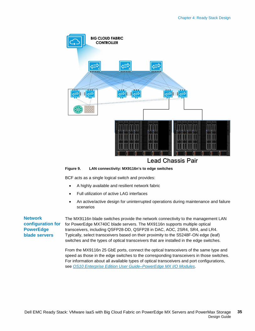
Figure 9. LAN connectivity: MX9116n’s to edge switches
BCF acts as a single logical switch and provides:
• A highly available and resilient network fabric
• Full utilization of active LAG interfaces
• An active/active design for uninterrupted operations during maintenance and failure scenarios
The MX9116n blade switches provide the network connectivity to the management LAN for PowerEdge MX740C blade servers. The MX9116n supports multiple optical transceivers, including QSFP28-DD, QSFP28 in DAC, AOC, 2SR4, SR4, and LR4. Typically, select transceivers based on their proximity to the S5248F-ON edge (leaf) switches and the types of optical transceivers that are installed in the edge switches.
From the MX9116n 25 GbE ports, connect the optical transceivers of the same type and speed as those in the edge switches to the corresponding transceivers in those switches. For information about all available types of optical transceivers and port configurations, see OS10 Enterprise Edition User Guide–PowerEdge MX I/O Modules.
Network configuration for PowerEdge blade servers
Chapter 4: Ready Stack Design
36 Dell EMC Ready Stack: VMware IaaS with Big Cloud Fabric on PowerEdge MX Servers and PowerMax Storage Design Guide
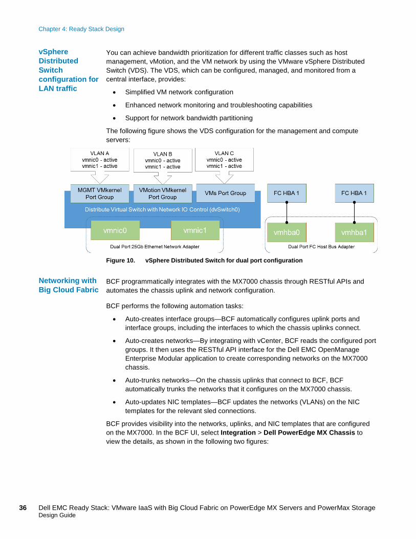
You can achieve bandwidth prioritization for different traffic classes such as host management, vMotion, and the VM network by using the VMware vSphere Distributed Switch (VDS). The VDS, which can be configured, managed, and monitored from a central interface, provides:
• Simplified VM network configuration
• Enhanced network monitoring and troubleshooting capabilities
• Support for network bandwidth partitioning
The following figure shows the VDS configuration for the management and compute servers:
Figure 10. vSphere Distributed Switch for dual port configuration
BCF programmatically integrates with the MX7000 chassis through RESTful APIs and automates the chassis uplink and network configuration.
BCF performs the following automation tasks:
• Auto-creates interface groups—BCF automatically configures uplink ports and interface groups, including the interfaces to which the chassis uplinks connect.
• Auto-creates networks—By integrating with vCenter, BCF reads the configured port groups. It then uses the RESTful API interface for the Dell EMC OpenManage Enterprise Modular application to create corresponding networks on the MX7000 chassis.
• Auto-trunks networks—On the chassis uplinks that connect to BCF, BCF automatically trunks the networks that it configures on the MX7000 chassis.
• Auto-updates NIC templates—BCF updates the networks (VLANs) on the NIC templates for the relevant sled connections.
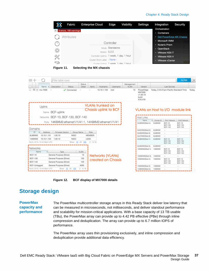
BCF provides visibility into the networks, uplinks, and NIC templates that are configured on the MX7000. In the BCF UI, select Integration > Dell PowerEdge MX Chassis to view the details, as shown in the following two figures:
vSphere Distributed Switch configuration for LAN traffic
Networking with Big Cloud Fabric
Chapter 4: Ready Stack Design
37 Dell EMC Ready Stack: VMware IaaS with Big Cloud Fabric on PowerEdge MX Servers and PowerMax Storage Design Guide
Figure 11. Selecting the MX chassis
Figure 12. BCF display of MX7000 details
Storage design The PowerMax multicontroller storage arrays in this Ready Stack deliver low latency that can be measured in microseconds, not milliseconds, and deliver standout performance and scalability for mission-critical applications. With a base capacity of 13 TB usable (TBu), the PowerMax array can provide up to 4.42 PB effective (PBe) through inline compression and deduplication. The array can provide up to 6.7 million IOPS of performance.
The PowerMax array uses thin provisioning exclusively, and inline compression and deduplication provide additional data efficiency.
PowerMax capacity and performance
Chapter 4: Ready Stack Design
38 Dell EMC Ready Stack: VMware IaaS with Big Cloud Fabric on PowerEdge MX Servers and PowerMax Storage Design Guide
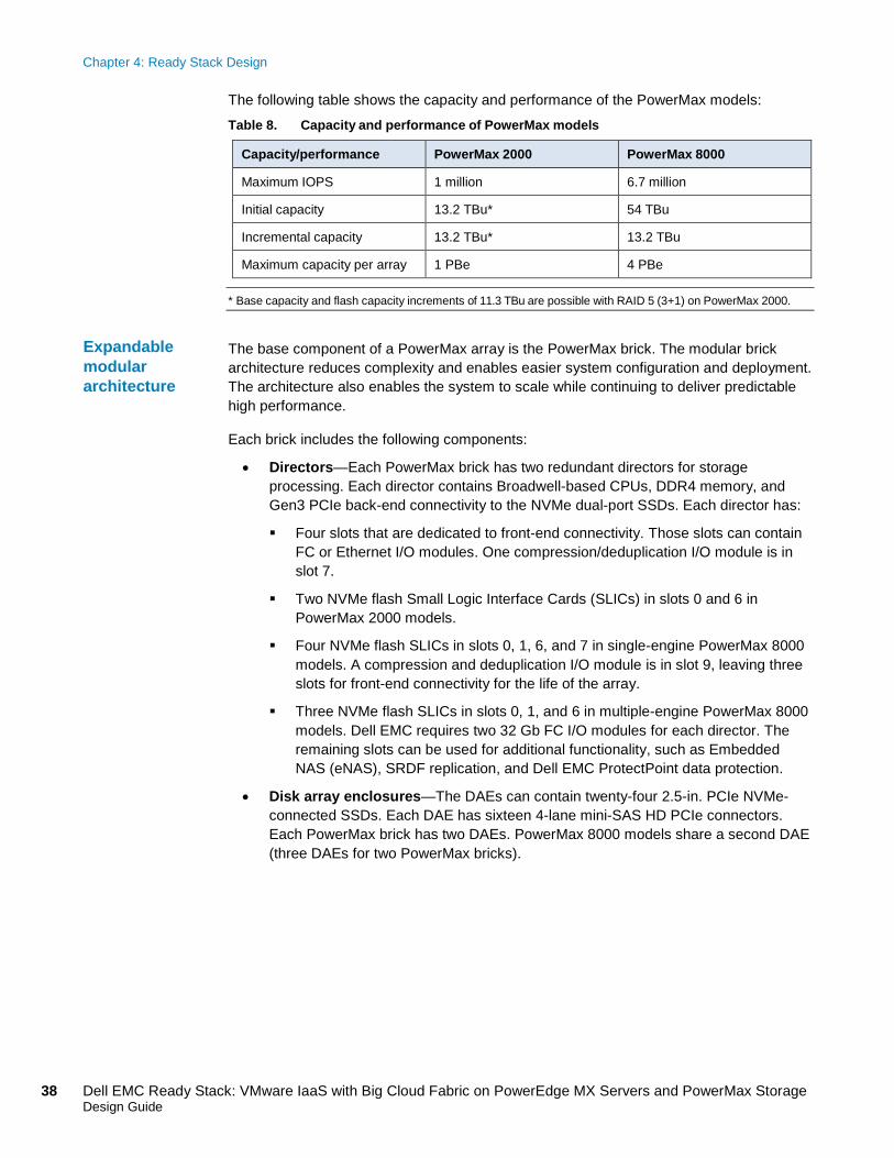
The following table shows the capacity and performance of the PowerMax models: Table 8. Capacity and performance of PowerMax models
Capacity/performance PowerMax 2000 PowerMax 8000
Maximum IOPS 1 million 6.7 million
Initial capacity 13.2 TBu* 54 TBu
Incremental capacity 13.2 TBu* 13.2 TBu
Maximum capacity per array 1 PBe 4 PBe
* Base capacity and flash capacity increments of 11.3 TBu are possible with RAID 5 (3+1) on PowerMax 2000.
The base component of a PowerMax array is the PowerMax brick. The modular brick architecture reduces complexity and enables easier system configuration and deployment. The architecture also enables the system to scale while continuing to deliver predictable high performance.
Each brick includes the following components:
• Directors—Each PowerMax brick has two redundant directors for storage processing. Each director contains Broadwell-based CPUs, DDR4 memory, and Gen3 PCIe back-end connectivity to the NVMe dual-port SSDs. Each director has:
Four slots that are dedicated to front-end connectivity. Those slots can contain FC or Ethernet I/O modules. One compression/deduplication I/O module is in slot 7.
Two NVMe flash Small Logic Interface Cards (SLICs) in slots 0 and 6 in PowerMax 2000 models.
Four NVMe flash SLICs in slots 0, 1, 6, and 7 in single-engine PowerMax 8000 models. A compression and deduplication I/O module is in slot 9, leaving three slots for front-end connectivity for the life of the array.
Three NVMe flash SLICs in slots 0, 1, and 6 in multiple-engine PowerMax 8000 models. Dell EMC requires two 32 Gb FC I/O modules for each director. The remaining slots can be used for additional functionality, such as Embedded NAS (eNAS), SRDF replication, and Dell EMC ProtectPoint data protection.
• Disk array enclosures—The DAEs can contain twenty-four 2.5-in. PCIe NVMe-connected SSDs. Each DAE has sixteen 4-lane mini-SAS HD PCIe connectors. Each PowerMax brick has two DAEs. PowerMax 8000 models share a second DAE (three DAEs for two PowerMax bricks).
Expandable modular architecture
Chapter 4: Ready Stack Design
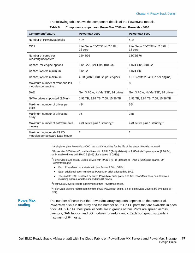
39 Dell EMC Ready Stack: VMware IaaS with Big Cloud Fabric on PowerEdge MX Servers and PowerMax Storage Design Guide
The following table shows the component details of the PowerMax models: Table 9. Component comparison: PowerMax 2000 and PowerMax 8000
Component/feature PowerMax 2000 PowerMax 8000
Number of PowerMax bricks 1–2 1–8
CPU Intel Xeon E5-2650-v4 2.5 GHz 12 core
Intel Xeon E5-2697-v4 2.8 GHz 18 core
Number of cores per CPU/engine/system
12/48/96 18/72/576
Cache: Per-engine options 512 Gb/1,024 Gb/2,048 Gb 1,024 Gb/2,048 Gb
Cache: System minimum 512 Gb 1,024 Gb
Cache: System maximum 4 TB (with 2,048 Gb per engine) 16 TB (with 2,048 Gb per engine)
Maximum number of front-end I/O modules per engine
8 81
DAE Gen 3 PCIe, NVMe SSD, 24 drives Gen 3 PCIe, NVMe SSD, 24 drives
NVMe drives supported (2.5-in.) 1.92 TB, 3.84 TB, 7.68, 15.36 TB 1.92 TB, 3.84 TB, 7.68, 15.36 TB
Maximum number of drives per brick
482 363
Maximum number of drives per array
96 288
Maximum number of software data movers
4 (3 active plus 1 standby)4 4 (3 active plus 1 standby)5
Maximum number eNAS I/O modules per software Data Mover
2 2
1 A single-engine PowerMax 8000 has six I/O modules for the life of the array. Slot 9 is not used. 2 PowerMax 2000 has 40 usable drives with RAID 5 (7+1) (default) or RAID 6 (6+2) plus spares (2 DAEs), or 44 usable drives with RAID 5 (3+1) plus spares (2 DAEs). 3
PowerMax 8000 has 32 usable drives with RAID 5 (7+1) (default) or RAID 6 (6+2) plus spares. On PowerMax 8000: • Each PowerMax brick starts with two 24-slot 2.5-in. DAEs. • Each additional even-numbered PowerMax brick adds a third DAE.
• The middle DAE is shared between PowerMax brick pairs. The first PowerMax brick has 38 drives including spares, and the second has 34 drives.
4 Four Data Movers require a minimum of two PowerMax bricks. 5 Four Data Movers require a minimum of two PowerMax bricks. Six or eight Data Movers are available by RPQ.
The number of hosts that the PowerMax array supports depends on the number of PowerMax bricks in the array and the number of 32 Gb FC ports that are available in each brick. All 32 Gb FC host parallel ports are in groups of four. Ports are spread across directors, SAN fabrics, and I/O modules for redundancy. Each port group supports a maximum of 64 hosts.
PowerMax scaling
Chapter 4: Ready Stack Design
40 Dell EMC Ready Stack: VMware IaaS with Big Cloud Fabric on PowerEdge MX Servers and PowerMax Storage Design Guide
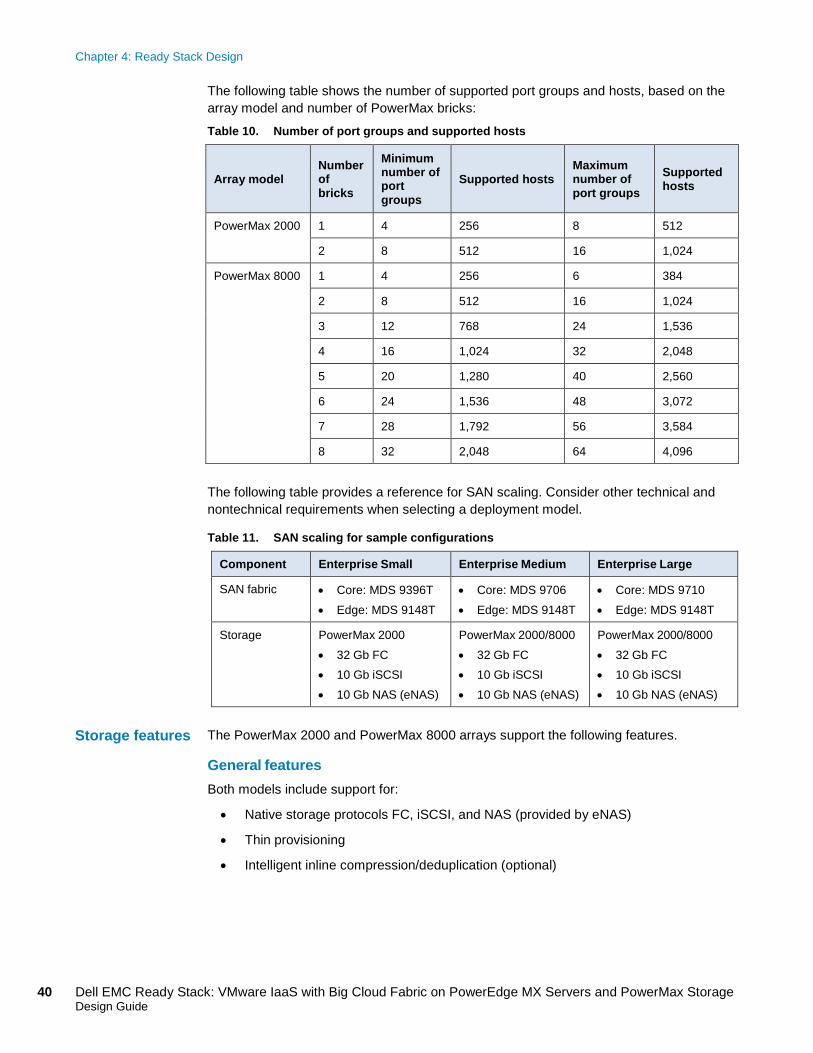
The following table shows the number of supported port groups and hosts, based on the array model and number of PowerMax bricks:
Table 10. Number of port groups and supported hosts
Array model Number of bricks
Minimum number of port groups
Supported hosts Maximum number of port groups
Supported hosts
PowerMax 2000 1 4 256 8 512
2 8 512 16 1,024
PowerMax 8000 1 4 256 6 384
2 8 512 16 1,024
3 12 768 24 1,536
4 16 1,024 32 2,048
5 20 1,280 40 2,560
6 24 1,536 48 3,072
7 28 1,792 56 3,584
8 32 2,048 64 4,096
The following table provides a reference for SAN scaling. Consider other technical and nontechnical requirements when selecting a deployment model.
Table 11. SAN scaling for sample configurations
Component Enterprise Small Enterprise Medium Enterprise Large
SAN fabric • Core: MDS 9396T • Edge: MDS 9148T
• Core: MDS 9706 • Edge: MDS 9148T
• Core: MDS 9710 • Edge: MDS 9148T
Storage PowerMax 2000 • 32 Gb FC • 10 Gb iSCSI • 10 Gb NAS (eNAS)
PowerMax 2000/8000 • 32 Gb FC • 10 Gb iSCSI • 10 Gb NAS (eNAS)
PowerMax 2000/8000 • 32 Gb FC • 10 Gb iSCSI • 10 Gb NAS (eNAS)
The PowerMax 2000 and PowerMax 8000 arrays support the following features.
General features Both models include support for:
• Native storage protocols FC, iSCSI, and NAS (provided by eNAS)
• Thin provisioning
• Intelligent inline compression/deduplication (optional)
Storage features
Chapter 4: Ready Stack Design
41 Dell EMC Ready Stack: VMware IaaS with Big Cloud Fabric on PowerEdge MX Servers and PowerMax Storage Design Guide
Encryption Data at Rest Encryption (D@RE) provides hardware-based, on-array, back-end encryption for PowerMax arrays by using SAS I/O modules that incorporate AES-XTS inline data encryption. These modules encrypt and decrypt data as it is being written to or read from disk. D@RE supports either an internal embedded key manager or an external, enterprise-grade key manager that is accessible through Key Management Interoperability Protocol (KMIP). The PowerMax arrays support the following external key managers:
• Gemalto SafeNet KeySecure
• IBM Security Key Lifecycle Manager
Replication Dell EMC TimeFinder software provides native local replication on the PowerMax arrays. The software delivers point-in-time copies of volumes that can be used for backup, decision support, data warehouse refreshes, or any other process that requires parallel access to production data. TimeFinder SnapVX technology provides snapshot and cloning functionality. TimeFinder SnapVX features include:
• Targetless snapshots—Creates a snapshot of an entire storage group with one command
• Secure snaps—Prevents the intentional or unintentional deletion of snapshots
• Cascading snapshots—Provides flexibility to present multiple versions of a snapshot
Symmetrix Remote Data Facility SRDF operates in the following modes:
• Synchronous mode (SRDF/S)—Maintains a real-time copy at arrays that are located within 200 km. Writes from the production host are acknowledged from the local array when they are written to cache at the remote array.
• Asynchronous mode (SRDF/A)—Maintains a dependent-write-consistent copy at arrays that are located at unlimited distances. The local array immediately acknowledges writes from the production host, so replication does not affect host performance. Data at the remote array is typically only seconds behind the primary site.
• SRDF/Metro—Makes target devices read/write accessible to a host or to multiple hosts in clusters. Hosts write to both the R1 and R2 sides of SRDF device pairs, and SRDF/Metro ensures that each copy remains current and consistent.
• Adaptive copy mode (SRDF/DM)—Moves large amounts of data quickly with minimal host impact.
Each PowerMax model can be purchased with two primary software packages—Essentials and Pro. Each package includes software licenses to meet many customer needs, as shown in the following table.
Note: Additional software licenses can be purchased separately.
Software licensing
Chapter 4: Ready Stack Design
42 Dell EMC Ready Stack: VMware IaaS with Big Cloud Fabric on PowerEdge MX Servers and PowerMax Storage Design Guide
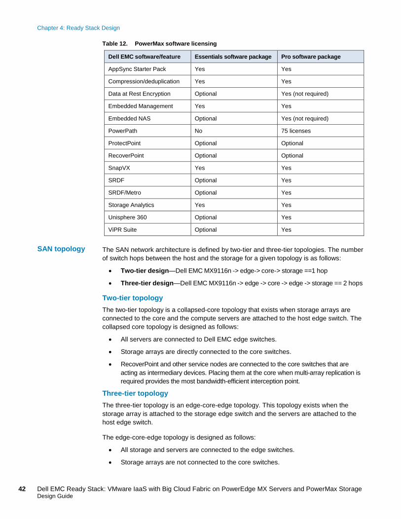
Table 12. PowerMax software licensing
Dell EMC software/feature Essentials software package Pro software package
AppSync Starter Pack Yes Yes
Compression/deduplication Yes Yes
Data at Rest Encryption Optional Yes (not required)
Embedded Management Yes Yes
Embedded NAS Optional Yes (not required)
PowerPath No 75 licenses
ProtectPoint Optional Optional
RecoverPoint Optional Optional
SnapVX Yes Yes
SRDF Optional Yes
SRDF/Metro Optional Yes
Storage Analytics Yes Yes
Unisphere 360 Optional Yes
ViPR Suite Optional Yes
The SAN network architecture is defined by two-tier and three-tier topologies. The number of switch hops between the host and the storage for a given topology is as follows:
• Two-tier design—Dell EMC MX9116n -> edge-> core-> storage ==1 hop
• Three-tier design—Dell EMC MX9116n -> edge -> core -> edge -> storage == 2 hops
Two-tier topology The two-tier topology is a collapsed-core topology that exists when storage arrays are connected to the core and the compute servers are attached to the host edge switch. The collapsed core topology is designed as follows:
• All servers are connected to Dell EMC edge switches.
• Storage arrays are directly connected to the core switches.
• RecoverPoint and other service nodes are connected to the core switches that are acting as intermediary devices. Placing them at the core when multi-array replication is required provides the most bandwidth-efficient interception point.
Three-tier topology The three-tier topology is an edge-core-edge topology. This topology exists when the storage array is attached to the storage edge switch and the servers are attached to the host edge switch.
The edge-core-edge topology is designed as follows:
• All storage and servers are connected to the edge switches.
• Storage arrays are not connected to the core switches.
SAN topology
Chapter 4: Ready Stack Design
43 Dell EMC Ready Stack: VMware IaaS with Big Cloud Fabric on PowerEdge MX Servers and PowerMax Storage Design Guide
• RecoverPoint and other service nodes can directly connect to the core switches that are acting as intermediary devices. If multi-array replication is required, placing these capabilities at the core provides the most bandwidth-efficient interception point.
The data center fabric SAN is a classic redundant A/B fabric with the following connectivity:
• Edge switches do not connect directly to other edge switches. Edge switches can provide connectivity for:
Storage arrays
Compute resources
Data protection resources
• Core switches connect only to other core switches in the same data center SAN fabric. Core switches can provide connectivity for:
Storage arrays
Data protection resources
Future meshing at the core switches for expansion
Edge switches Each edge switch connects to the core switch by using eight 32 Gb uplinks. The Dell EMC Connectrix MDS 9148T and 9396T multilayer fabric switches are fixed-form-factor switches. The Dell EMC Connectrix MDS 9706 Multilayer Director and Dell EMC Connectrix MDS 9710 Multilayer Director support 48-port modules with 32 Gb line-rate FC ports, requiring a minimum of three Fabric-3 modules to be populated.
Populate all ports on the 48-FC-port modules with a 32 Gb, small-form-factor pluggable device (SFP).
Management design This section provides an overview of the Ready Stack management infrastructure and the software components that run on VMs within the management cluster.
The management infrastructure consists of a minimum of three PowerEdge R640 servers that form a management cluster. Management components are virtualized to provide high availability. Redundant 10/25 GbE uplinks to the network infrastructure, redundant 16 Gb/s FC uplinks to the storage array, and vSphere High Availability (vSphere HA) ensure that management components stay online. The Dell EMC PowerSwitch S4148T is used for OOB connectivity, and iDRAC ports in each management and compute cluster connect to the switch. The iDRAC ports on the management server connect to the S4148T-ON switch; the iDRAC ports on the blade server connect through the MX9116n to the S4148T-ON switch.
Data center fabric SAN connectivity
Uplink support
Introduction
Management infrastructure
Chapter 4: Ready Stack Design
44 Dell EMC Ready Stack: VMware IaaS with Big Cloud Fabric on PowerEdge MX Servers and PowerMax Storage Design Guide
OpenManage Enterprise Modular Edition runs on the MX9002m modules, which uplink to the S4148T-ON switches through the Management Services Module (MSM) Ethernet interface.
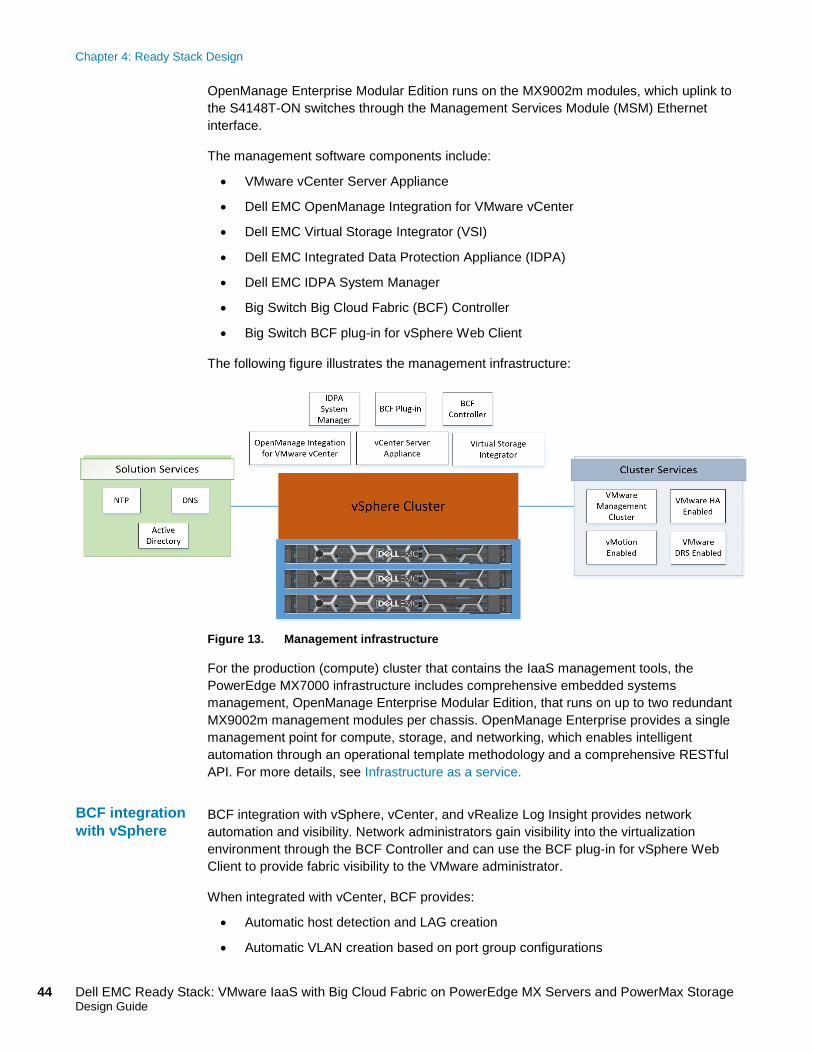
The management software components include:
• VMware vCenter Server Appliance
• Dell EMC OpenManage Integration for VMware vCenter
• Dell EMC Virtual Storage Integrator (VSI)
• Dell EMC Integrated Data Protection Appliance (IDPA)
• Dell EMC IDPA System Manager
• Big Switch Big Cloud Fabric (BCF) Controller
• Big Switch BCF plug-in for vSphere Web Client
The following figure illustrates the management infrastructure:
Figure 13. Management infrastructure
For the production (compute) cluster that contains the IaaS management tools, the PowerEdge MX7000 infrastructure includes comprehensive embedded systems management, OpenManage Enterprise Modular Edition, that runs on up to two redundant MX9002m management modules per chassis. OpenManage Enterprise provides a single management point for compute, storage, and networking, which enables intelligent automation through an operational template methodology and a comprehensive RESTful API. For more details, see Infrastructure as a service.
BCF integration with vSphere, vCenter, and vRealize Log Insight provides network automation and visibility. Network administrators gain visibility into the virtualization environment through the BCF Controller and can use the BCF plug-in for vSphere Web Client to provide fabric visibility to the VMware administrator.
When integrated with vCenter, BCF provides:
• Automatic host detection and LAG creation
• Automatic VLAN creation based on port group configurations
BCF integration with vSphere
Chapter 4: Ready Stack Design
45 Dell EMC Ready Stack: VMware IaaS with Big Cloud Fabric on PowerEdge MX Servers and PowerMax Storage Design Guide
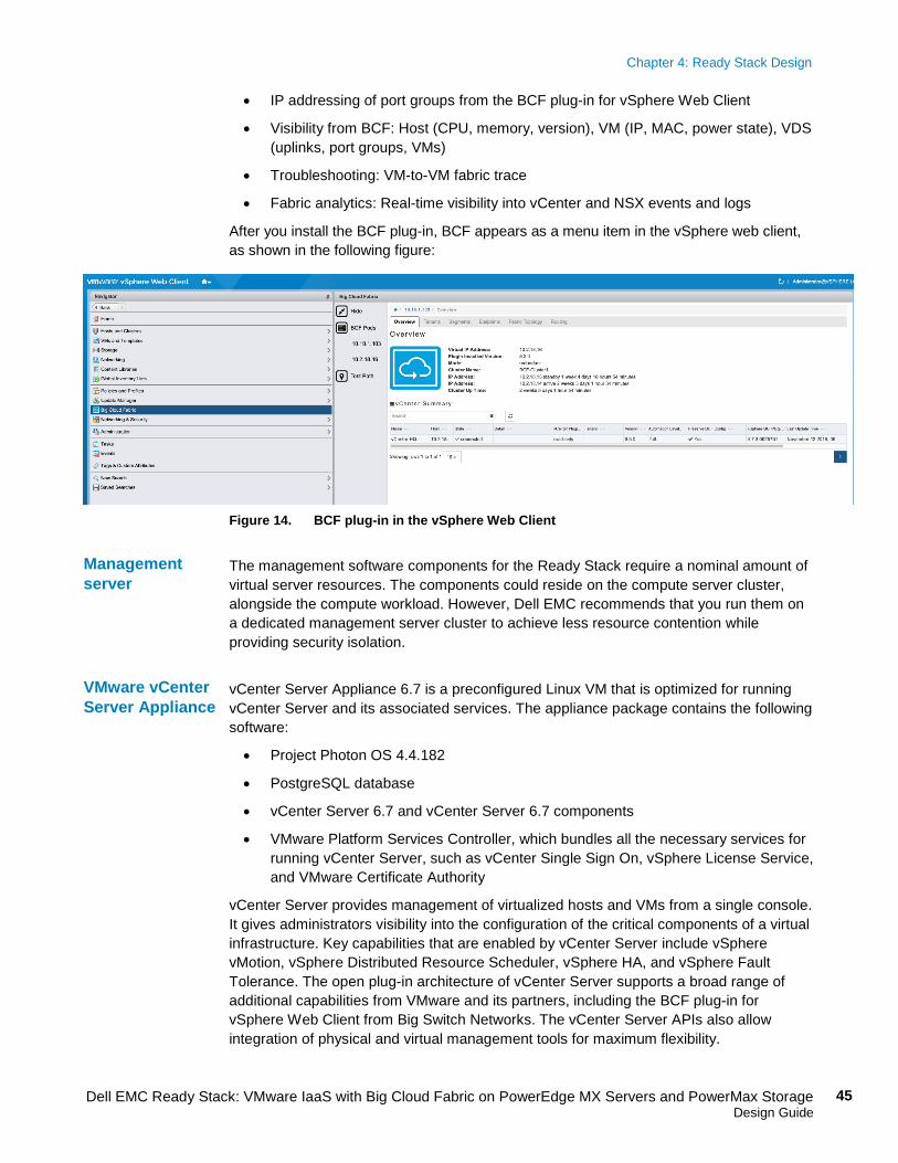
• IP addressing of port groups from the BCF plug-in for vSphere Web Client
• Visibility from BCF: Host (CPU, memory, version), VM (IP, MAC, power state), VDS (uplinks, port groups, VMs)
• Troubleshooting: VM-to-VM fabric trace
• Fabric analytics: Real-time visibility into vCenter and NSX events and logs
After you install the BCF plug-in, BCF appears as a menu item in the vSphere web client, as shown in the following figure:
Figure 14. BCF plug-in in the vSphere Web Client
The management software components for the Ready Stack require a nominal amount of virtual server resources. The components could reside on the compute server cluster, alongside the compute workload. However, Dell EMC recommends that you run them on a dedicated management server cluster to achieve less resource contention while providing security isolation.
vCenter Server Appliance 6.7 is a preconfigured Linux VM that is optimized for running vCenter Server and its associated services. The appliance package contains the following software:
• Project Photon OS 4.4.182
• PostgreSQL database
• vCenter Server 6.7 and vCenter Server 6.7 components
• VMware Platform Services Controller, which bundles all the necessary services for running vCenter Server, such as vCenter Single Sign On, vSphere License Service, and VMware Certificate Authority
vCenter Server provides management of virtualized hosts and VMs from a single console. It gives administrators visibility into the configuration of the critical components of a virtual infrastructure. Key capabilities that are enabled by vCenter Server include vSphere vMotion, vSphere Distributed Resource Scheduler, vSphere HA, and vSphere Fault Tolerance. The open plug-in architecture of vCenter Server supports a broad range of additional capabilities from VMware and its partners, including the BCF plug-in for vSphere Web Client from Big Switch Networks. The vCenter Server APIs also allow integration of physical and virtual management tools for maximum flexibility.
Management server
VMware vCenter Server Appliance
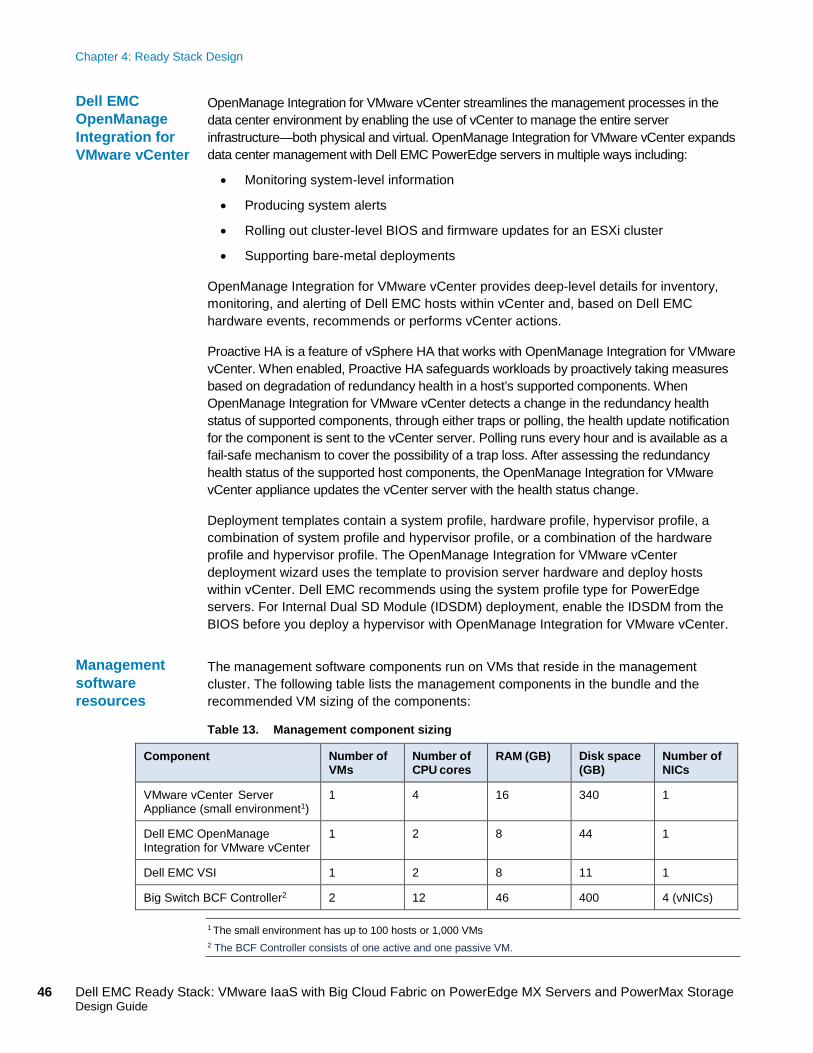
Chapter 4: Ready Stack Design
46 Dell EMC Ready Stack: VMware IaaS with Big Cloud Fabric on PowerEdge MX Servers and PowerMax Storage Design Guide
OpenManage Integration for VMware vCenter streamlines the management processes in the data center environment by enabling the use of vCenter to manage the entire server infrastructure—both physical and virtual. OpenManage Integration for VMware vCenter expands data center management with Dell EMC PowerEdge servers in multiple ways including:
• Monitoring system-level information
• Producing system alerts
• Rolling out cluster-level BIOS and firmware updates for an ESXi cluster
• Supporting bare-metal deployments
OpenManage Integration for VMware vCenter provides deep-level details for inventory, monitoring, and alerting of Dell EMC hosts within vCenter and, based on Dell EMC hardware events, recommends or performs vCenter actions.
Proactive HA is a feature of vSphere HA that works with OpenManage Integration for VMware vCenter. When enabled, Proactive HA safeguards workloads by proactively taking measures based on degradation of redundancy health in a host’s supported components. When OpenManage Integration for VMware vCenter detects a change in the redundancy health status of supported components, through either traps or polling, the health update notification for the component is sent to the vCenter server. Polling runs every hour and is available as a fail-safe mechanism to cover the possibility of a trap loss. After assessing the redundancy health status of the supported host components, the OpenManage Integration for VMware vCenter appliance updates the vCenter server with the health status change.
Deployment templates contain a system profile, hardware profile, hypervisor profile, a combination of system profile and hypervisor profile, or a combination of the hardware profile and hypervisor profile. The OpenManage Integration for VMware vCenter deployment wizard uses the template to provision server hardware and deploy hosts within vCenter. Dell EMC recommends using the system profile type for PowerEdge servers. For Internal Dual SD Module (IDSDM) deployment, enable the IDSDM from the BIOS before you deploy a hypervisor with OpenManage Integration for VMware vCenter.
The management software components run on VMs that reside in the management cluster. The following table lists the management components in the bundle and the recommended VM sizing of the components:
Table 13. Management component sizing
Component Number of VMs
Number of CPU cores
RAM (GB) Disk space (GB)
Number of NICs
VMware vCenter Server Appliance (small environment1)
1 4 16 340 1
Dell EMC OpenManage Integration for VMware vCenter
1 2 8 44 1
Dell EMC VSI 1 2 8 11 1
Big Switch BCF Controller2 2 12 46 400 4 (vNICs)
1 The small environment has up to 100 hosts or 1,000 VMs 2 The BCF Controller consists of one active and one passive VM.
Dell EMC OpenManage Integration for VMware vCenter
Management software resources
Chapter 5: References
47 Dell EMC Ready Stack: VMware IaaS with Big Cloud Fabric on PowerEdge MX Servers and PowerMax Storage Design Guide
Chapter 5 References
This chapter presents the following topics:
Dell EMC documentation .................................................................................. 48
VMware documentation .................................................................................... 48
Big Switch Networks documentation .............................................................. 48
Chapter 5: References
48 Dell EMC Ready Stack: VMware IaaS with Big Cloud Fabric on PowerEdge MX Servers and PowerMax Storage Design Guide
Dell EMC documentation The following Dell EMC documentation provides additional and relevant information. Access to these documents depends on your login credentials. If you do not have access to a document, contact your Dell EMC representative.
• The Dell EMC PowerMax: Family Overview White Paper
• Dell EMC PowerMax: Data Reduction Technical White Paper
• Dell EMC Knowledge Base: iDRAC9
• Dell EMC PowerEdge MX7000 Spec Sheet
• Dell EMC PowerEdge Modular Infrastructure Quick Reference Guide
• Dell EMC PowerEdge R640 Installation and Service Manual
• Dell EMC Virtual Storage Integrator (VSI) for VMware vSphere Client Product Guide
• OS10 Enterprise Edition User Guide – PowerEdge MX I/O Modules
• Dell EMC Integrated Data Protection Appliance (IDPA) DP4400 Data Sheet
• OpenManage Integration for VMware vCenter Web Client Installation Guide
• PowerSwitch S4148F-ON/S4148T-ON/S4148FE-ON
• PowerSwitch S5248F-ON
• VSI for VMware vSphere Web Client
• Dell EMC Connectrix Switches
VMware documentation For additional information from VMware, see VMware vSphere Documentation.
Big Switch Networks documentation For additional information from Big Switch Networks, see Big Cloud Fabric.


![Environmental and fate ecotoxicity models BCF Base-Line Modeloasis-lmc.org/media/63060/BCF Base-Line model.pdf · BCF Base-line model - Mitigating factors water octanol [ ] [ ] neutral](https://img.pdfslide.net/doc/110x75/5fa8305a751a19180c1090f6/environmental-and-fate-ecotoxicity-models-bcf-base-line-modeloasis-lmcorgmedia63060bcf.jpg)