Embed Size (px)
Citation preview
Dell Storage CenterSC4020 Storage System
Owner’s Manual

Notes, Cautions, and WarningsNOTE: A NOTE indicates important information that helps you make better use of your computer.
CAUTION: A CAUTION indicates either potential damage to hardware or loss of data and tells you how to avoid the problem.
WARNING: A WARNING indicates a potential for property damage, personal injury, or death.
Copyright © 2015 Dell Inc. All rights reserved. This product is protected by U.S. and international copyright and intellectual property laws. Dell™ and the Dell logo are trademarks of Dell Inc. in the United States and/or other jurisdictions. All other marks and names mentioned herein may be trademarks of their respective companies.
2015 - 12
Rev. G
Contents
About this Guide.......................................................................................................5Revision History..................................................................................................................................... 5
Audience................................................................................................................................................ 5
Contacting Dell......................................................................................................................................5
Related Publications.............................................................................................................................. 5
1 About the SC4020 Storage System....................................................................7Storage Center Hardware Components...............................................................................................7
SC4020 Storage System..................................................................................................................7
Switches........................................................................................................................................... 7
Expansion Enclosures...................................................................................................................... 7
Storage Center Architecture Options...................................................................................................8
Storage Center Communication.......................................................................................................... 9
SC4020 Storage System with Fibre Channel IO Ports...................................................................9
SC4020 Storage System with iSCSI IO Ports................................................................................10
Front-End Connectivity................................................................................................................. 12
Back-End Connectivity..................................................................................................................12
System Administration...................................................................................................................12
SC4020 Storage System Hardware.....................................................................................................12
SC4020 Storage System Front-Panel Features and Indicators................................................... 13
SC4020 Storage System Back-Panel Features and Indicators.................................................... 14
SC4020 Storage System Storage Controller Features and Indicators ........................................15
SC4020 Storage System Drives.....................................................................................................19
SC4020 Storage System Drive Numbering.................................................................................. 19
2 Connect the Front End...................................................................................... 20Front-End Connectivity Modes.......................................................................................................... 20
Virtual Port Mode.......................................................................................................................... 20
Legacy Mode................................................................................................................................. 22
Types of Redundancy for Front-End Connections........................................................................... 24
Failover Behavior........................................................................................................................... 25
Multipath IO...................................................................................................................................25
Fibre Channel Zoning......................................................................................................................... 26
WWN Zoning Guidelines...............................................................................................................26
Port Zoning Guidelines..................................................................................................................27
Cabling SAN-Attached Host Servers.................................................................................................. 27
Connecting to Fibre Channel Host Servers..................................................................................27
Connecting to iSCSI Host Servers................................................................................................ 39
Cabling the Ethernet Management Port............................................................................................ 49
3
Labeling the Ethernet Management Cables.................................................................................50
Cabling the Embedded Ports for iSCSI Replication........................................................................... 51
Cabling the Replication Port for iSCSI Replication.......................................................................51
Cabling the Management Port and Replication Port for iSCSI Replication.................................51
Cabling the Embedded Ports for iSCSI Host Connectivity................................................................52
Two iSCSI Networks using the Embedded Ethernet Ports on a Storage System with Fibre
Channel Storage Controllers........................................................................................................ 52
Two iSCSI Networks Using the Embedded Ethernet Ports on a Storage System with iSCSI
Storage Controllers....................................................................................................................... 54
3 SC4020 Storage System Technical Specifications.......................................56Technical Specifications..................................................................................................................... 56
4
Preface
About this GuideThis guide describes the features and technical specifications of an SC4020 storage system.
Revision History
Document Number: 680-100-001
Revision Date Description
A May 2014 Initial release
B June 2014 Removed a reference to an internal document and added additional information about the BMC
C August 2014 Added information about iSCSI front-end connectivity support
D October 2014 Added information about SFP+ transceiver modules and contacting Dell technical support
E November 2014 Corrected errors found during validation.
F June 2015 Added information about new features for SC4020 storage systems running Storage Center 6.6.4 or later.
G December 2015 Added information about 16 Gb Fibre Channel front-end connectivity.
AudienceThe information provided in this Owner’s Manual is intended for use by Dell end users.
Contacting DellDell provides several online and telephone-based support and service options. Availability varies by country and product, and some services may not be available in your area.
To contact Dell for sales, technical support, or customer service issues, go to www.dell.com/support.
• For customized support, enter your system Service Tag on the support page and click Submit.
• For general support, browse the product list on the support page and select your product.
Related PublicationsThe following documentation is available for the SC4020 Storage System.
• Dell Storage Center SC4020 Storage System Getting Started Guide
Provides information about an SC4020 storage system, such as installation instructions and technical specifications.
5

• Dell Storage Center Release Notes
Contains information about new features and known and resolved issues for the Storage Center software.
• Dell Storage Center System Manager Administrator’s Guide
Describes the Storage Center System Manager software that manages an individual Storage Center.
• Dell TechCenter
Provides technical white papers, best practice guides, and frequently asked questions about Dell Storage products. Go to http://en.community.dell.com/techcenter/storage/.
6
1About the SC4020 Storage SystemThe SC4020 storage system provides the central processing capabilities for the Storage Center Operating System (OS), application software (Storage Center System Manager) and management of RAID storage.
Storage Center Hardware ComponentsThe Storage Center described in this document consists of an SC4020 storage system, enterprise-class switches, and expansion enclosures.
To allow for storage expansion, the SC4020 storage system supports multiple SC200/SC220 expansion enclosures. An SC4020 running Storage Center 6.6.4 or later, also supports up to two SC280 expansion enclosures.
NOTE: The cabling between the storage system, switches, and host servers is referred to as front‐end connectivity. The cabling between the storage system and expansion enclosures is referred to as back-end connectivity.
SC4020 Storage System
The SC4020 is a 2U storage system that supports up to 24 internal 2.5–inch hot-swappable SAS hard drives installed vertically side by side.
The SC4020 storage system contains two storage controllers with multiple IO ports that provide communication with servers and expansion enclosures.
Switches
Dell offers enterprise-class switches as part of the total Storage Center solution.
The SC4020 supports Fibre Channel (FC) and Ethernet switches, which provide robust connectivity to servers and allow for the use of redundant transport paths. Fibre Channel (FC) or Ethernet switches can provide connectivity to a remote Storage Center to allow for replication of data. In addition, Ethernet switches provide connectivity to a management network to allow configuration, administration, and management of the Storage Center.
Expansion Enclosures
Expansion enclosures allow the data storage capabilities of the SC4020 storage system to be expanded beyond the 24 internal disks in the storage system chassis.
The number of disks that an SC4020 storage system supports depends on the version of the Storage Center operating system:
• An SC4020 running Storage Center 6.6.4 or later supports a total of 192 disks per Storage Center system.
• An SC4020 running Storage Center 6.6.3 or earlier supports a total of 120 disks per Storage Center system.
About the SC4020 Storage System 7
This total includes the disks in the storage system chassis and the disks in the SC200/SC220 expansion enclosures or SC280 expansion enclosures.
Storage Center 6.6.4 or Later
An SC4020 running Storage Center 6.6.4 or later supports:
• Up fourteen SC200 expansion enclosures
• Up to seven SC220 expansion enclosures
• Any combination of SC200/SC220 expansion enclosures, as long as the total disk count of the system does not exceed 192
• Up to two SC280 expansion enclosures
NOTE: An SC4020 storage system cannot be connected to both SC200/SC220 expansion enclosures and SC280 expansion enclosures at the same time. The SC4020 supports only a single chain of SC200/SC220 expansion enclosures or a single chain of SC280 expansion enclosures.
Storage Center 6.6.3 or Earlier
An SC4020 running Storage Center 6.6.3 or earlier supports:
• Up eight SC200 expansion enclosures
• Up to four SC220 expansion enclosures
• Any combination of SC200/SC220 expansion enclosures, as long as the total disk count of the system does not exceed 120
Storage Center Architecture Options
A Storage Center with an SC4020 storage system can be deployed in the following configurations:
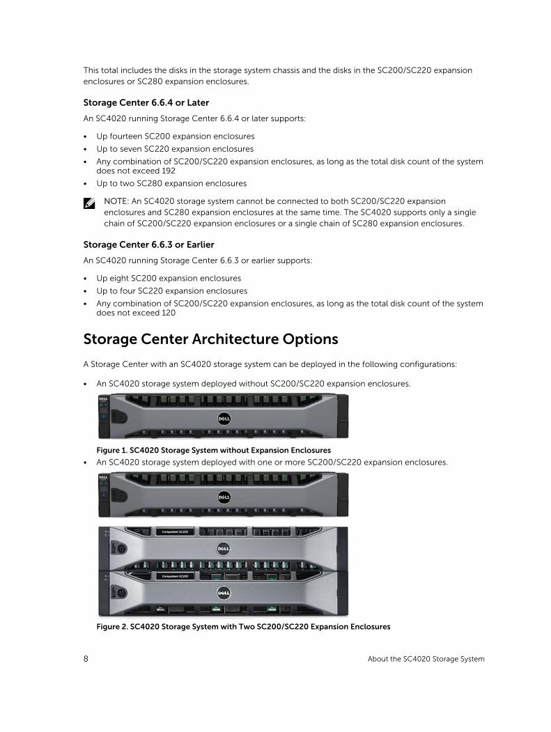
• An SC4020 storage system deployed without SC200/SC220 expansion enclosures.
Figure 1. SC4020 Storage System without Expansion Enclosures
• An SC4020 storage system deployed with one or more SC200/SC220 expansion enclosures.
Figure 2. SC4020 Storage System with Two SC200/SC220 Expansion Enclosures
8 About the SC4020 Storage System
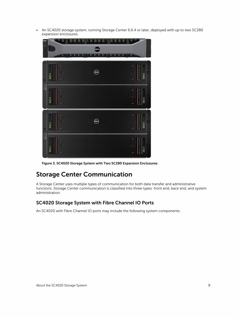
• An SC4020 storage system, running Storage Center 6.6.4 or later, deployed with up to two SC280 expansion enclosures.
Figure 3. SC4020 Storage System with Two SC280 Expansion Enclosures
Storage Center CommunicationA Storage Center uses multiple types of communication for both data transfer and administrative functions. Storage Center communication is classified into three types: front end, back end, and system administration.
SC4020 Storage System with Fibre Channel IO Ports
An SC4020 with Fibre Channel IO ports may include the following system components:
About the SC4020 Storage System 9
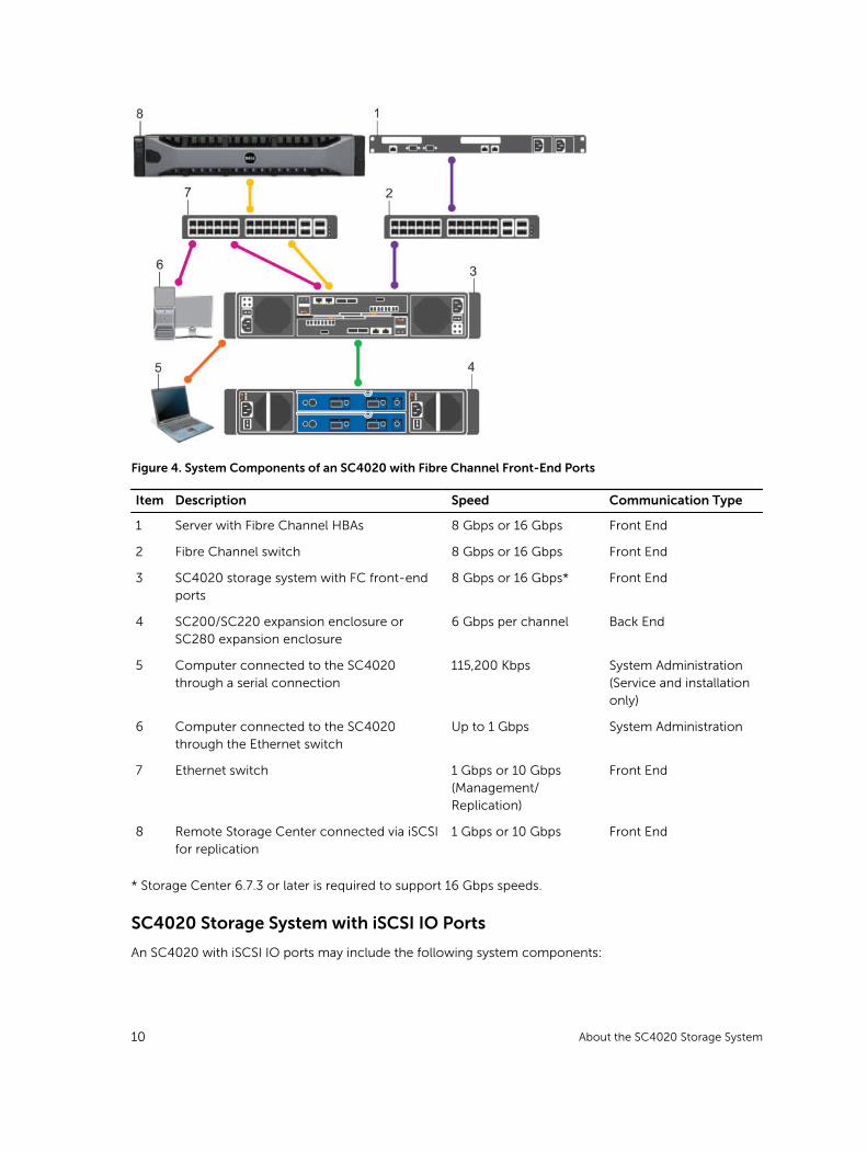
Figure 4. System Components of an SC4020 with Fibre Channel Front-End Ports
Item Description Speed Communication Type
1 Server with Fibre Channel HBAs 8 Gbps or 16 Gbps Front End
2 Fibre Channel switch 8 Gbps or 16 Gbps Front End
3 SC4020 storage system with FC front-end ports
8 Gbps or 16 Gbps* Front End
4 SC200/SC220 expansion enclosure or SC280 expansion enclosure
6 Gbps per channel Back End
5 Computer connected to the SC4020 through a serial connection
115,200 Kbps System Administration (Service and installation only)
6 Computer connected to the SC4020 through the Ethernet switch
Up to 1 Gbps System Administration
7 Ethernet switch 1 Gbps or 10 Gbps (Management/Replication)
Front End
8 Remote Storage Center connected via iSCSI for replication
1 Gbps or 10 Gbps Front End
* Storage Center 6.7.3 or later is required to support 16 Gbps speeds.
SC4020 Storage System with iSCSI IO Ports
An SC4020 with iSCSI IO ports may include the following system components:
10 About the SC4020 Storage System
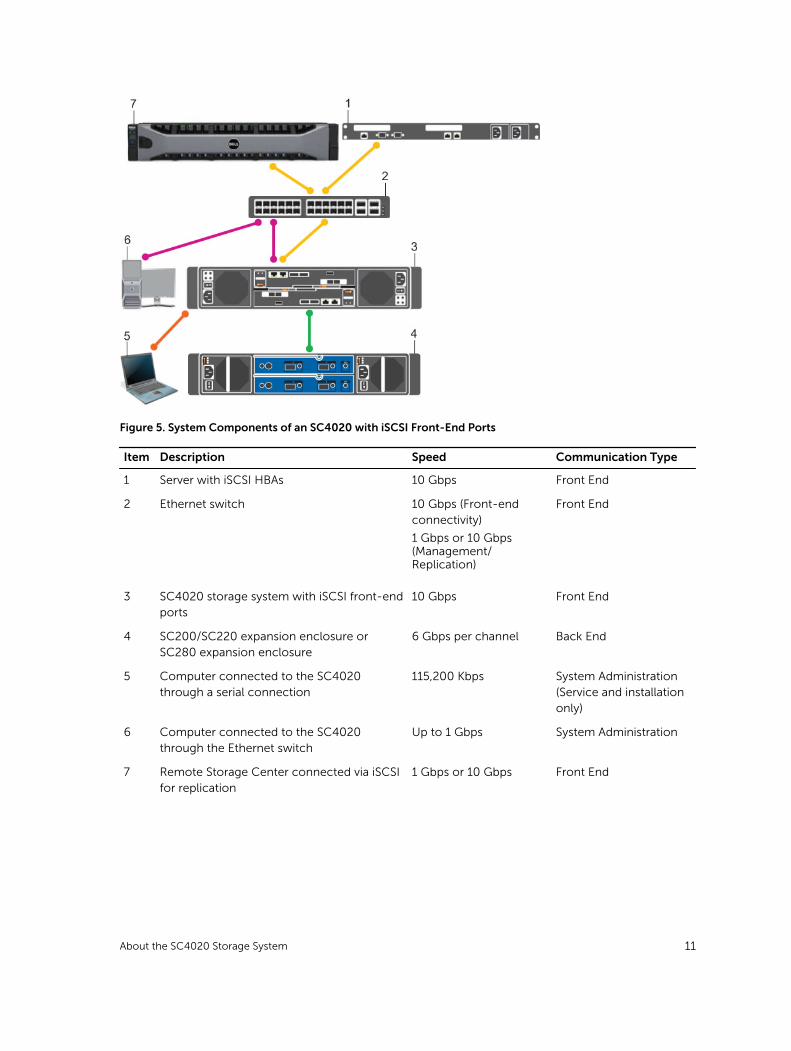
Figure 5. System Components of an SC4020 with iSCSI Front-End Ports
Item Description Speed Communication Type
1 Server with iSCSI HBAs 10 Gbps Front End
2 Ethernet switch 10 Gbps (Front-end connectivity)
1 Gbps or 10 Gbps (Management/Replication)
Front End
3 SC4020 storage system with iSCSI front-end ports
10 Gbps Front End
4 SC200/SC220 expansion enclosure or SC280 expansion enclosure
6 Gbps per channel Back End
5 Computer connected to the SC4020 through a serial connection
115,200 Kbps System Administration (Service and installation only)
6 Computer connected to the SC4020 through the Ethernet switch
Up to 1 Gbps System Administration
7 Remote Storage Center connected via iSCSI for replication
1 Gbps or 10 Gbps Front End
About the SC4020 Storage System 11
Front-End Connectivity
Front-end connectivity provides IO paths from servers to a storage system and replication paths from one Storage Center to another Storage Center. The SC4020 storage system provides the following types of front-end connectivity:
• Fibre Channel: Hosts, servers, or Network Attached Storage (NAS) appliances access storage by connecting to the storage system Fibre Channel ports through one or more Fibre Channel switches. Connecting host servers directly to the storage system, without using Fibre Channel switches, is not supported.
When replication is licensed, the SC4020 can use the front-end Fibre Channel ports to replicate data to another Storage Center.
• iSCSI: Hosts, servers, or Network Attached Storage (NAS) appliances access storage by connecting to the storage system iSCSI ports through one or more Ethernet switches. Connecting host servers directly to the storage system, without using Ethernet switches, is not supported.
When replication is licensed, the SC4020 can use the front-end iSCSI ports to replicate data to another Storage Center.
NOTE: When replication is licensed on an SC4020 running Storage Center 6.6.4 or later, the SC4020 can use the embedded MGMT and REPL ports to perform iSCSI replication to another Storage Center. In addition, the SC4020 can use the embedded MGMT and REPL ports as front-end iSCSI ports for connectivity to host servers.
Back-End Connectivity
Back-end connectivity is strictly between the storage system and expansion enclosures, which hold the physical drives that provide back-end expansion storage.
An SC4020 storage system supports back-end connectivity to multiple expansion enclosures.
System Administration
To perform system administration, communicate with the Storage Center using the Ethernet ports and serial ports on the storage controllers.
• Ethernet port: Used for configuration, administration, and management of Storage Center.
NOTE: The baseboard management controller (BMC) does not have a separate physical port on the SC4020. The BMC is accessed through the same Ethernet port that is used for Storage Center configuration, administration, and management.
• Serial port: Used for initial configuration of the storage controllers. In addition, it is used to perform support only functions when instructed by Dell Technical Support Services.
SC4020 Storage System HardwareThe SC4020 storage system ships with Dell Enterprise Plus drives, two redundant power supply/cooling fan modules, and two redundant storage controllers.
Each storage controller contains the front-end, back-end, and management communication ports of the storage system.
12 About the SC4020 Storage System
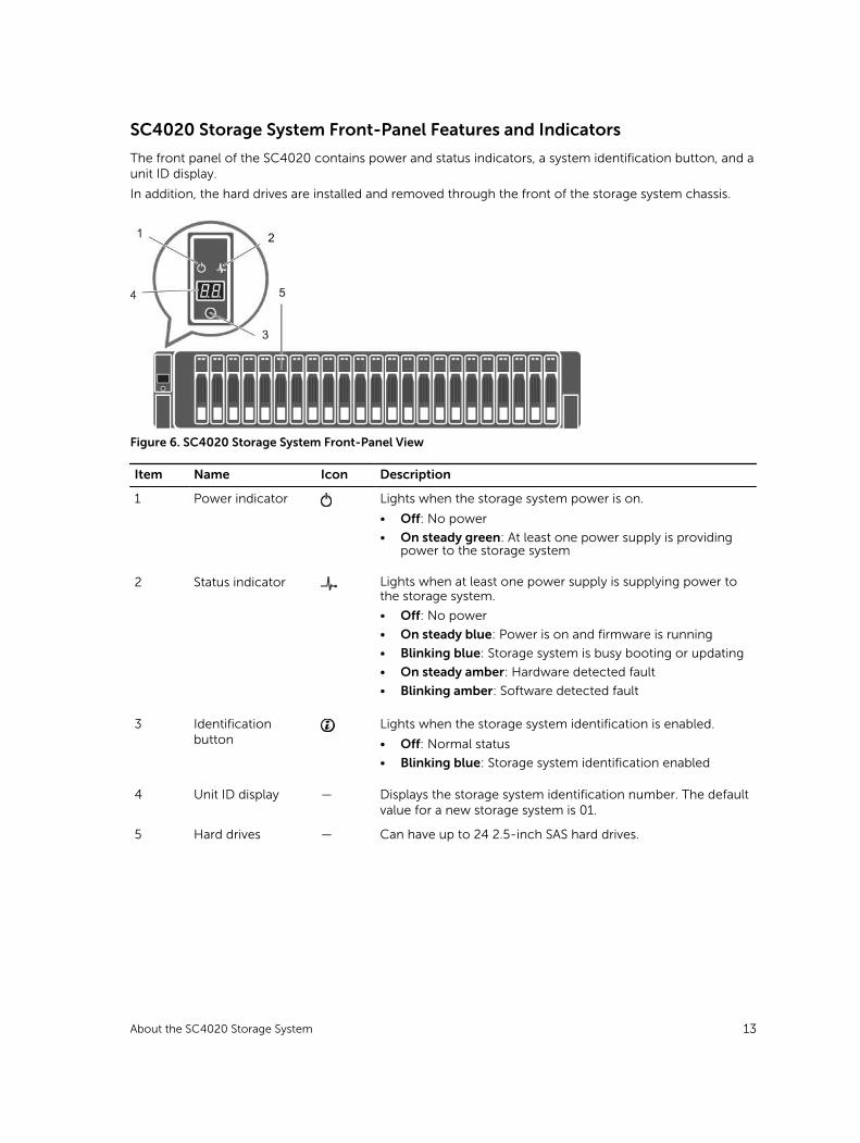
SC4020 Storage System Front-Panel Features and Indicators
The front panel of the SC4020 contains power and status indicators, a system identification button, and a unit ID display.
In addition, the hard drives are installed and removed through the front of the storage system chassis.
Figure 6. SC4020 Storage System Front-Panel View
Item Name Icon Description
1 Power indicator Lights when the storage system power is on.
• Off: No power
• On steady green: At least one power supply is providing power to the storage system
2 Status indicator Lights when at least one power supply is supplying power to the storage system.
• Off: No power
• On steady blue: Power is on and firmware is running
• Blinking blue: Storage system is busy booting or updating
• On steady amber: Hardware detected fault
• Blinking amber: Software detected fault
3 Identification button
Lights when the storage system identification is enabled.
• Off: Normal status
• Blinking blue: Storage system identification enabled
4 Unit ID display — Displays the storage system identification number. The default value for a new storage system is 01.
5 Hard drives — Can have up to 24 2.5-inch SAS hard drives.
About the SC4020 Storage System 13
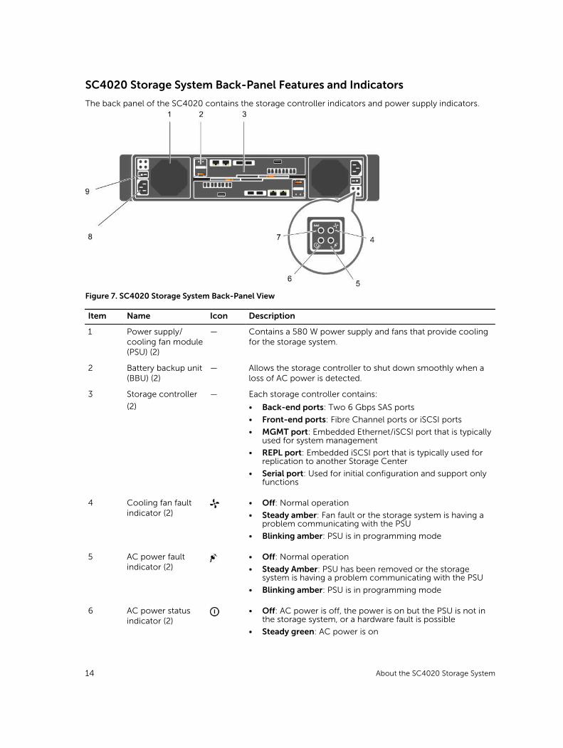
SC4020 Storage System Back-Panel Features and Indicators
The back panel of the SC4020 contains the storage controller indicators and power supply indicators.
Figure 7. SC4020 Storage System Back-Panel View
Item Name Icon Description
1 Power supply/cooling fan module (PSU) (2)
— Contains a 580 W power supply and fans that provide cooling for the storage system.
2 Battery backup unit (BBU) (2)
— Allows the storage controller to shut down smoothly when a loss of AC power is detected.
3 Storage controller
(2)
— Each storage controller contains:
• Back-end ports: Two 6 Gbps SAS ports
• Front-end ports: Fibre Channel ports or iSCSI ports
• MGMT port: Embedded Ethernet/iSCSI port that is typically used for system management
• REPL port: Embedded iSCSI port that is typically used for replication to another Storage Center
• Serial port: Used for initial configuration and support only functions
4 Cooling fan fault indicator (2)
• Off: Normal operation
• Steady amber: Fan fault or the storage system is having a problem communicating with the PSU
• Blinking amber: PSU is in programming mode
5 AC power fault indicator (2)
• Off: Normal operation
• Steady Amber: PSU has been removed or the storage system is having a problem communicating with the PSU
• Blinking amber: PSU is in programming mode
6 AC power status indicator (2)
• Off: AC power is off, the power is on but the PSU is not in the storage system, or a hardware fault is possible
• Steady green: AC power is on
14 About the SC4020 Storage System
Item Name Icon Description
• Blinking green: AC power is on and the PSU is in standby mode
7 DC power fault indicator (2)
• Off: Normal operation
• Steady amber: PSU has been removed, a DC or other hardware fault has occurred, or the storage system is having a problem communicating with the PSU
• Blinking amber: PSU is in programming mode
8 Power socket (2) — Accepts a standard computer power cord.
9 Power switch (2) — Controls power for the storage system. Each PSU has one switch.
SC4020 Storage System Storage Controller Features and Indicators
The SC4020 storage system includes two storage controllers in two interface slots.
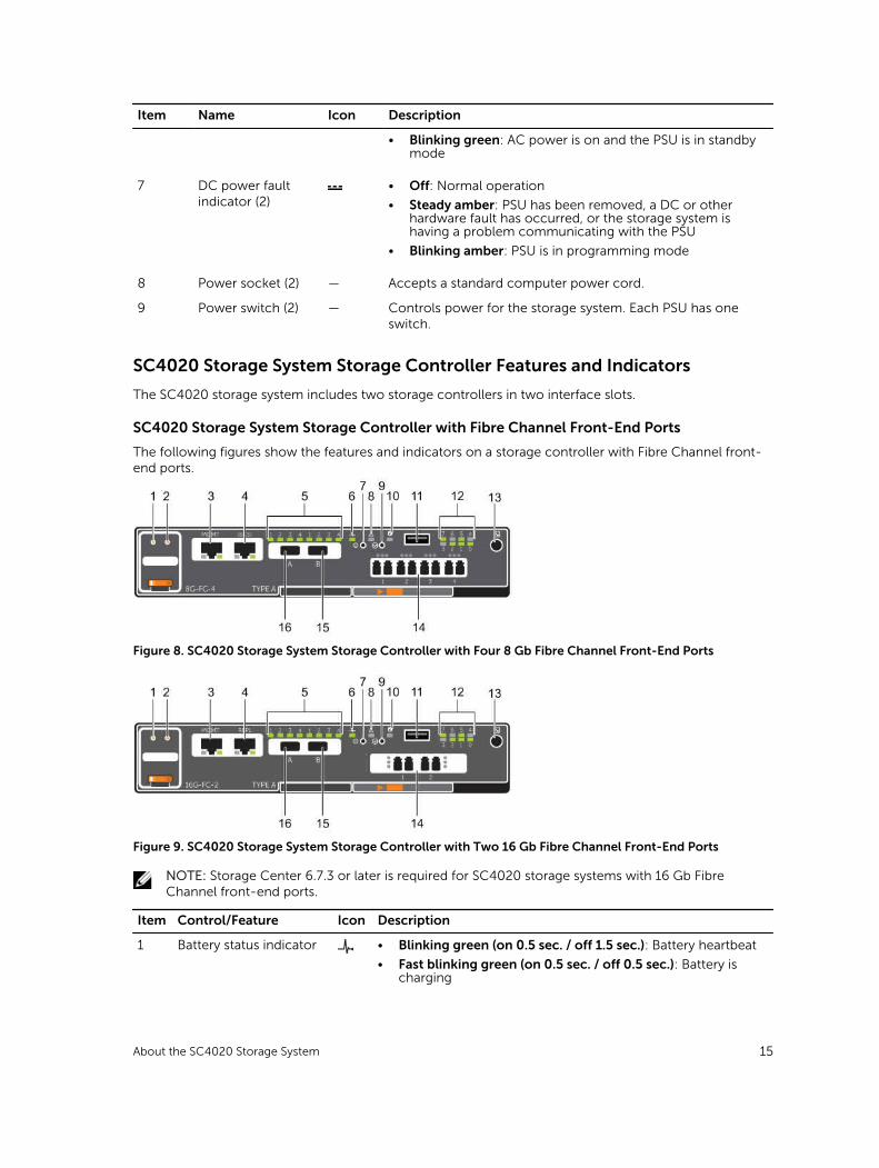
SC4020 Storage System Storage Controller with Fibre Channel Front-End Ports
The following figures show the features and indicators on a storage controller with Fibre Channel front-end ports.
Figure 8. SC4020 Storage System Storage Controller with Four 8 Gb Fibre Channel Front-End Ports
Figure 9. SC4020 Storage System Storage Controller with Two 16 Gb Fibre Channel Front-End Ports
NOTE: Storage Center 6.7.3 or later is required for SC4020 storage systems with 16 Gb Fibre Channel front-end ports.
Item Control/Feature Icon Description
1 Battery status indicator • Blinking green (on 0.5 sec. / off 1.5 sec.): Battery heartbeat
• Fast blinking green (on 0.5 sec. / off 0.5 sec.): Battery is charging
About the SC4020 Storage System 15
Item Control/Feature Icon Description
• Steady green: Battery is ready
2 Battery fault indicator • Off: No faults
• Blinking amber: Correctable fault detected
• Steady amber: Uncorrectable fault detected; replace battery
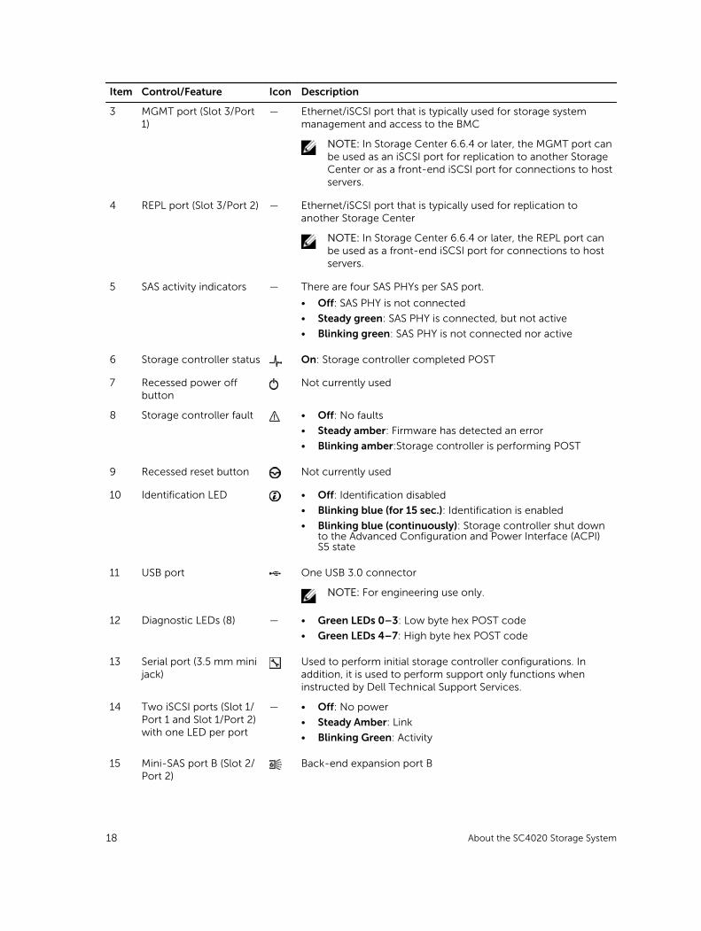
3 MGMT port (Slot 3/Port 1)
— Ethernet/iSCSI port that is typically used for storage system management and access to the BMC
NOTE: In Storage Center 6.6.4 or later, the MGMT port can be used as an iSCSI port for replication to another Storage Center or as a front-end iSCSI port for connections to host servers.
4 iSCSI port (Slot 3/Port 2) — Ethernet/iSCSI port that is typically used for replication to another Storage Center (requires a replication license)
NOTE: In Storage Center 6.6.4 or later, the iSCSI port can be used as a front-end port for connections to host servers.
5 SAS activity indicators — There are four SAS PHYs per SAS port.
• Off: SAS PHY is not connected
• Steady green: SAS PHY is connected, but not active
• Blinking green: SAS PHY is not connected nor active
6 Storage controller status On: Storage controller completed POST
7 Recessed power off button
Not currently used
8 Storage controller fault • Off: No faults
• Steady amber: Firmware has detected an error
• Blinking amber: Storage controller is performing POST
9 Recessed reset button Not currently used
10 Identification LED • Off: Identification disabled
• Blinking blue (for 15 sec.): Identification is enabled
• Blinking blue (continuously): Storage controller shut down to the Advanced Configuration and Power Interface (ACPI) S5 state
11 USB port One USB 3.0 connector
NOTE: For engineering use only.
12 Diagnostic LEDs (8) — • Green LEDs 0–3: Low byte hex POST code
• Green LEDs 4–7: High byte hex POST code
13 Serial port (3.5 mm mini jack)
Used to perform initial storage controller configurations. In addition, it is used to perform support only functions when instructed by Dell Technical Support Services.
14 Two options: — LEDs for the four 8 Gb Fibre Channel ports:• All off: No power
16 About the SC4020 Storage System
Item Control/Feature Icon Description
• Four Fibre Channel ports (Slot 1/Port 1, Slot 1/Port 2, Slot 1/Port 3, and Slot 1/Port 4) with three LEDs per port
• Two Fibre Channel ports (Slot 1/Port 1 and Slot 1/Port 2) with three LEDs per port
• All on: Booting up
• Blinking amber: 2 Gbps activity
• Blinking green: 4 Gbps activity
• Blinking yellow: 8 Gbps activity
• Blinking amber and yellow: Beacon
• All blinking (simultaneous): Firmware initialized
• All blinking (alternating): Firmware fault
LEDs for the two 16 Gb Fibre Channel ports:
• All off: No power
• All on: Booting up
• Blinking amber: 4 Gbps activity
• Blinking green: 8 Gbps activity
• Blinking yellow: 16 Gbps activity
• Blinking amber and yellow: Beacon
• All blinking (simultaneous): Firmware initialized
• All blinking (alternating): Firmware fault
15 Mini-SAS port B (Slot 2/Port 2)
Back-end expansion port B
16 Mini-SAS port A (Slot 2/Port 1)
Back-end expansion port A
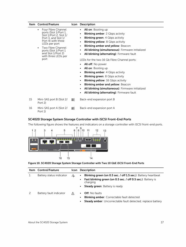
SC4020 Storage System Storage Controller with iSCSI Front-End Ports
The following figure shows the features and indicators on a storage controller with iSCSI front-end ports.
Figure 10. SC4020 Storage System Storage Controller with Two 10 GbE iSCSI Front-End Ports
Item Control/Feature Icon Description
1 Battery status indicator • Blinking green (on 0.5 sec. / off 1.5 sec.): Battery heartbeat
• Fast blinking green (on 0.5 sec. / off 0.5 sec.): Battery is charging
• Steady green: Battery is ready
2 Battery fault indicator • Off: No faults
• Blinking amber: Correctable fault detected
• Steady amber: Uncorrectable fault detected; replace battery
About the SC4020 Storage System 17
Item Control/Feature Icon Description
3 MGMT port (Slot 3/Port 1)
— Ethernet/iSCSI port that is typically used for storage system management and access to the BMC
NOTE: In Storage Center 6.6.4 or later, the MGMT port can be used as an iSCSI port for replication to another Storage Center or as a front-end iSCSI port for connections to host servers.
4 REPL port (Slot 3/Port 2) — Ethernet/iSCSI port that is typically used for replication to another Storage Center
NOTE: In Storage Center 6.6.4 or later, the REPL port can be used as a front-end iSCSI port for connections to host servers.
5 SAS activity indicators — There are four SAS PHYs per SAS port.
• Off: SAS PHY is not connected
• Steady green: SAS PHY is connected, but not active
• Blinking green: SAS PHY is not connected nor active
6 Storage controller status On: Storage controller completed POST
7 Recessed power off button
Not currently used
8 Storage controller fault • Off: No faults
• Steady amber: Firmware has detected an error
• Blinking amber:Storage controller is performing POST
9 Recessed reset button Not currently used
10 Identification LED • Off: Identification disabled
• Blinking blue (for 15 sec.): Identification is enabled
• Blinking blue (continuously): Storage controller shut down to the Advanced Configuration and Power Interface (ACPI) S5 state
11 USB port One USB 3.0 connector
NOTE: For engineering use only.
12 Diagnostic LEDs (8) — • Green LEDs 0–3: Low byte hex POST code
• Green LEDs 4–7: High byte hex POST code
13 Serial port (3.5 mm mini jack)
Used to perform initial storage controller configurations. In addition, it is used to perform support only functions when instructed by Dell Technical Support Services.
14 Two iSCSI ports (Slot 1/Port 1 and Slot 1/Port 2) with one LED per port
— • Off: No power
• Steady Amber: Link
• Blinking Green: Activity
15 Mini-SAS port B (Slot 2/Port 2)
Back-end expansion port B
18 About the SC4020 Storage System
Item Control/Feature Icon Description
16 Mini-SAS port A (Slot 2/Port 1)
Back-end expansion port A
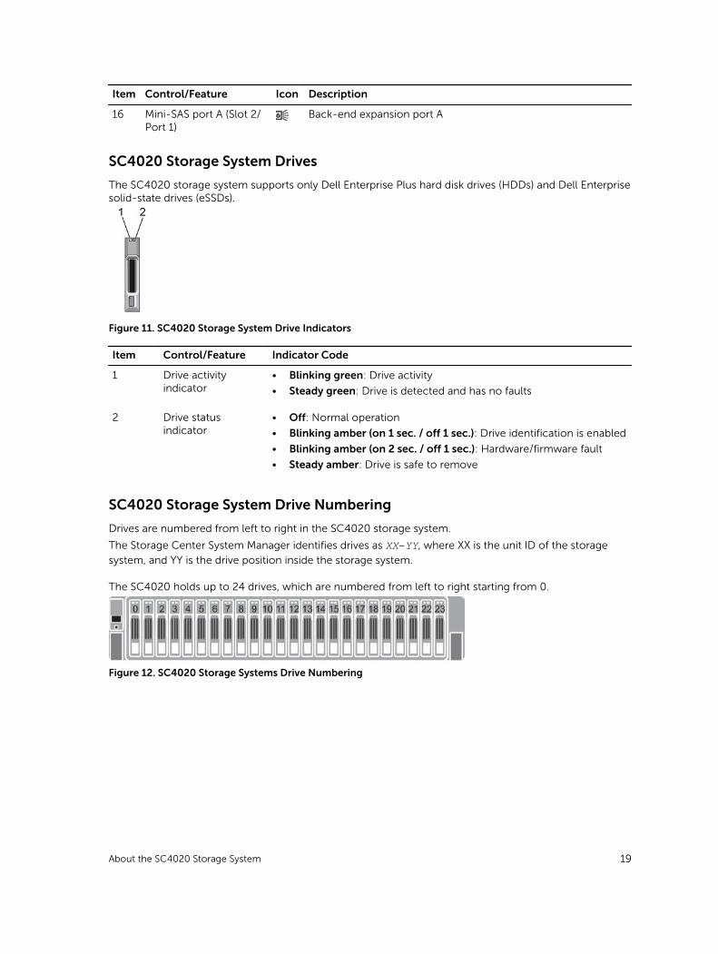
SC4020 Storage System Drives
The SC4020 storage system supports only Dell Enterprise Plus hard disk drives (HDDs) and Dell Enterprise solid-state drives (eSSDs).
Figure 11. SC4020 Storage System Drive Indicators
Item Control/Feature Indicator Code
1 Drive activity indicator
• Blinking green: Drive activity
• Steady green: Drive is detected and has no faults
2 Drive status indicator
• Off: Normal operation
• Blinking amber (on 1 sec. / off 1 sec.): Drive identification is enabled
• Blinking amber (on 2 sec. / off 1 sec.): Hardware/firmware fault
• Steady amber: Drive is safe to remove
SC4020 Storage System Drive Numbering
Drives are numbered from left to right in the SC4020 storage system.
The Storage Center System Manager identifies drives as XX-YY, where XX is the unit ID of the storage
system, and YY is the drive position inside the storage system.
The SC4020 holds up to 24 drives, which are numbered from left to right starting from 0.
Figure 12. SC4020 Storage Systems Drive Numbering
About the SC4020 Storage System 19
2Connect the Front EndFront-end cabling refers to the connections between the storage system and external devices such as host servers or another Storage Center.
Front‐end connections can be made using Fibre Channel or iSCSI interfaces. Dell recommends connecting the storage system to host servers using the most redundant option available.
Front-End Connectivity ModesStorage Center uses either virtual port mode or legacy mode to transport data to servers that use SAN storage.
In virtual port mode, all front-end IO ports are active, and if one port fails the load is distributed between the remaining ports within the same fault domain.
In legacy mode, front-end IO ports are configured in pairs of primary and reserved ports.
Virtual Port Mode
Virtual port mode provides port and storage controller redundancy by connecting multiple active ports to each Fibre Channel or Ethernet switch.
In virtual port mode, each physical port has a WWN (World Wide Name) and a virtual WWN. Servers target only the virtual WWNs. During normal conditions, all ports process IO. If a port or storage controller failure occurs, a virtual WWN moves to another physical WWN in the same fault domain. When the failure is resolved and ports are rebalanced, the virtual port returns to the preferred physical port.
Virtual port mode provides the following advantages over legacy mode:
• Increased connectivity: Because all ports are active, additional front-end bandwidth is available without sacrificing redundancy.
• Improved redundancy
– Fibre Channel: A Fibre Channel port can fail over to another Fibre Channel port in the same fault domain on the storage controller.
– iSCSI: In a single fault domain configuration, an iSCSI port can fail over to the other iSCSI port on the storage controller. In a two fault domain configuration, an iSCSI port cannot fail over to the other iSCSI port on the storage controller, if there are only two iSCSI ports on the storage controller. If there are four or more ports on a storage controller, then the iSCSI port can fail over.
• Simplified iSCSI configuration: Each fault domain has an iSCSI control port that coordinates discovery of the iSCSI ports in the domain. When a server targets the iSCSI port IP address, it automatically discovers all ports in the fault domain.
20 Connect the Front End
Fault Domains in Virtual Port Mode
Fault domains group front-end ports that are connected to the same network. Ports that belong to the same fault domain can fail over to each other because they have the same connectivity.
The following requirements apply to fault domains in virtual port mode:
• A separate fault domain must be created for each front-end Fibre Channel fabric or Ethernet network.
• A fault domain must contain a single type of transport media (FC or iSCSI, but not both).
• Dell recommends configuring at least two connections from each storage controller to each Fibre Channel fabric (fault domain) or Ethernet network (fault domain).
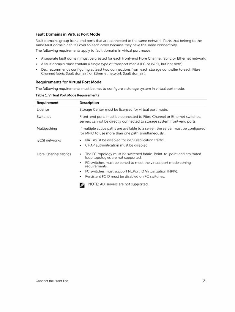
Requirements for Virtual Port Mode
The following requirements must be met to configure a storage system in virtual port mode.
Table 1. Virtual Port Mode Requirements
Requirement Description
License Storage Center must be licensed for virtual port mode.
Switches Front-end ports must be connected to Fibre Channel or Ethernet switches; servers cannot be directly connected to storage system front-end ports.
Multipathing If multiple active paths are available to a server, the server must be configured for MPIO to use more than one path simultaneously.
iSCSI networks • NAT must be disabled for iSCSI replication traffic.
• CHAP authentication must be disabled.
Fibre Channel fabrics • The FC topology must be switched fabric. Point-to-point and arbitrated loop topologies are not supported.
• FC switches must be zoned to meet the virtual port mode zoning requirements.
• FC switches must support N_Port ID Virtualization (NPIV).
• Persistent FCID must be disabled on FC switches.
NOTE: AIX servers are not supported.
Connect the Front End 21
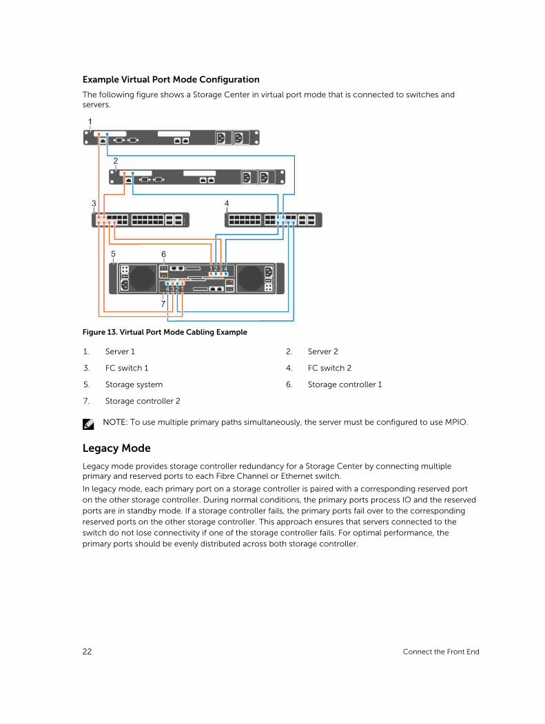
Example Virtual Port Mode Configuration
The following figure shows a Storage Center in virtual port mode that is connected to switches and servers.
Figure 13. Virtual Port Mode Cabling Example
1. Server 1 2. Server 2
3. FC switch 1 4. FC switch 2
5. Storage system 6. Storage controller 1
7. Storage controller 2
NOTE: To use multiple primary paths simultaneously, the server must be configured to use MPIO.
Legacy Mode
Legacy mode provides storage controller redundancy for a Storage Center by connecting multiple primary and reserved ports to each Fibre Channel or Ethernet switch.
In legacy mode, each primary port on a storage controller is paired with a corresponding reserved port on the other storage controller. During normal conditions, the primary ports process IO and the reserved ports are in standby mode. If a storage controller fails, the primary ports fail over to the corresponding reserved ports on the other storage controller. This approach ensures that servers connected to the switch do not lose connectivity if one of the storage controller fails. For optimal performance, the primary ports should be evenly distributed across both storage controller.
22 Connect the Front End
Fault Domains in Legacy Mode
Each pair of primary and reserved ports is grouped into a fault domain in the Storage Center software. The fault domain determines which ports are allowed to fail over to each other.
The following requirements apply to fault domains in legacy mode on a Storage Center:
• A fault domain must contain one type of transport media (FC or iSCSI, but not both).
• A fault domain must contain one primary port and one reserved port.
• The reserved port must be on a different storage controller than the primary port.
Requirements for Legacy Mode
The following requirements must be met to configure a storage system in legacy mode.
Table 2. Legacy Mode Requirements
Requirement Description
Storage controller front-end ports
On an SC4020 with FC front-end ports, each storage controller must have two FC front-end ports to connect two paths to each Fibre Channel switch.
On an SC4020 with iSCSI front-end ports, each storage controller must have two iSCSI front-end ports to connect two paths to each Ethernet switch.
Multipathing If multiple active paths are available to a server, the server must be configured for MPIO to use more than one path simultaneously.
Fibre Channel zoning Fibre Channel switches must be zoned to meet the legacy mode zoning requirements.
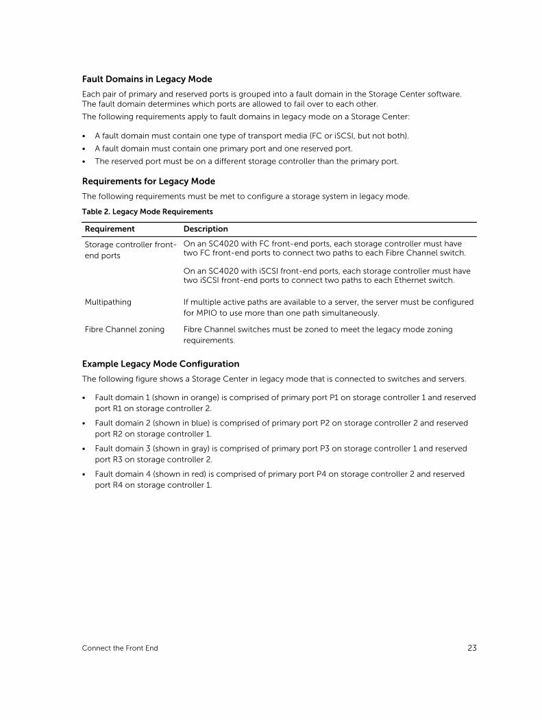
Example Legacy Mode Configuration
The following figure shows a Storage Center in legacy mode that is connected to switches and servers.
• Fault domain 1 (shown in orange) is comprised of primary port P1 on storage controller 1 and reserved port R1 on storage controller 2.
• Fault domain 2 (shown in blue) is comprised of primary port P2 on storage controller 2 and reserved port R2 on storage controller 1.
• Fault domain 3 (shown in gray) is comprised of primary port P3 on storage controller 1 and reserved port R3 on storage controller 2.
• Fault domain 4 (shown in red) is comprised of primary port P4 on storage controller 2 and reserved port R4 on storage controller 1.
Connect the Front End 23
Figure 14. Legacy Mode Cabling Example
1. Server 1 2. Server 2
3. Switch 1 4. Switch 2
5. Storage system 6. Storage controller 1
7. Storage controller 2
NOTE: To use multiple paths simultaneously, the server must be configured to use MPIO.
Types of Redundancy for Front-End ConnectionsFront-end redundancy is achieved by eliminating single points of failure that could cause a server to lose connectivity to the Storage Center.
Depending on how the Storage Center is cabled and configured, the following types of redundancy are available.
• Path redundancy: When multiple paths are available from a server to a storage system, a server configured for multipath IO (MPIO) can use multiple paths for IO. If a path becomes unavailable, the server continues to use the remaining active paths.
• Storage controller redundancy: If a storage controller becomes unavailable, the ports on the offline storage controller can move to the available storage controller. Both front-end connectivity modes (legacy mode and virtual port mode) provide storage controller redundancy.
• Port redundancy: If a port becomes unavailable, the port can move to another available port in the same fault domain. Port redundancy is available only in virtual port mode.
24 Connect the Front End
Failover Behavior
The Storage Center behaves in the following manner.
Table 3. Failover Behavior Scenarios
Scenario Virtual Port Mode Behavior Legacy Mode Behavior
Normal operating conditions
All ports are active and pass IO. • Primary ports pass IO.
• Reserved ports remain in a standby mode until a storage controller failure.
A single port becomes unavailable
An individual port moves to another port in the fault domain.
The port does not move over because there was no storage controller failure. If a second path is available, MPIO software on the server provides fault tolerance.
A storage controller becomes unavailable
Virtual ports on the offline storage controller can move to the available storage controller.
Primary ports on the offline storage controller can move to the reserved ports on the available storage controller.
Multipath IO
MPIO allows a server to use multiple paths for IO if they are available.
MPIO software offers redundancy at the path level. MPIO typically operates in a round-robin manner by sending packets first down one path and then the other. If a path becomes unavailable, MPIO software continues to send packets down the functioning path.
NOTE: MPIO is operating-system specific, and it loads as a driver on the server or it is part of the server operating system.
MPIO Behavior
The server must have at least two FC or iSCSI ports to use MPIO.
When MPIO is configured, a server can send IO to multiple ports on the same storage controller.
MPIO Configuration Instructions for Host Servers
To use MPIO, configure MPIO on the server prior to connecting the server to the Storage Center.
To configure MPIO on a host server, see the Dell Storage Center Best Practices document on the Dell TechCenter site (http://en.community.dell.com/techcenter/storage/) that corresponds to the server operating system. Depending on the operating system, you may need to install MPIO software or configure server options.
Table 4. MPIO Configuration Documents
Operating System Document with MPIO Instructions
IBM AIX Dell Storage Center with AIX Best Practices
Linux • Dell Storage Center with Red Hat Enterprise Linux (RHEL) 6x Best Practices
• Dell Storage Center with Red Hat Enterprise Linux (RHEL) 7x Best Practices
Connect the Front End 25

Operating System Document with MPIO Instructions
• Dell Compellent Best Practices: Storage Center with SUSE Linux Enterprise Server 11
VMware vSphere 5.x • Dell Storage Center Best Practices with VMware vSphere 5.x
• Dell Storage Center Best Practices with VMware vSphere 6.x
Windows Server 2008, 2008 R2, 2012, and 2012 R2
Dell Storage Center: Microsoft Multipath IO Best Practices
Fibre Channel ZoningWhen using Fibre Channel for front-end connectivity, zones must be established to ensure that storage is visible to the servers. Use the zoning concepts discussed in this section to plan the front-end connectivity before starting to cable the storage system.
Zoning can be applied to either the ports on switches or to the World Wide Names (WWNs) of the end devices.
Dell recommends creating zones using a single initiator host port and multiple Storage Center ports.
NOTE: WWN zoning is recommended for virtual port mode.
WWN Zoning Guidelines
When WWN zoning is configured, a device may reside on any port, or change physical ports and still be visible, because the switch is seeking a WWN.
Table 5. Guidelines for WWN Zoning
Connectivity Type Guidelines
Virtual port mode • Include all Storage Center virtual WWNs in a single zone.
• Include all Storage Center physical WWNs in a single zone.
• For each host server HBA port, create a zone that includes the single HBA WWN and multiple Storage Center virtual WWNs on the same switch.
Legacy mode • Include all Storage Center front-end WWNs or ports in a single zone.
• For each host server HBA port, create a zone that includes the single HBA WWN and multiple Storage Center virtual WWNs on the same switch.
For Fibre Channel replication:
• Include all Storage Center physical WWNs from Storage Center system A and Storage Center system B in a single zone.
• Include all Storage Center physical WWNs of Storage Center system A and the virtual WWNs of Storage Center system B on the particular fabric.
• Include all Storage Center physical WWNs of Storage Center system B and the virtual WWNs of Storage Center system A on the particular fabric.
NOTE: Some ports may not be used or dedicated for replication, however ports that are used must be in these zones.
26 Connect the Front End
Port Zoning Guidelines
When port zoning is configured, only specific switch ports are visible. If a storage device is moved to a different switch port that is not part of the zone, it is no longer visible to the other ports in the zone.
When you configure port zoning:
• Include all Storage Center front-end ports.
• For each host server port, create a zone that includes a single server HBA port and all Storage Center ports.
• Create server zones that contain all Storage Center front-end ports and a single server port.
• For Fibre Channel replication, include all Storage Center front-end ports from Storage Center system A and Storage Center system B in a single zone.
Cabling SAN-Attached Host ServersAn SC4020 storage system with Fibre Channel or iSCSI front-end ports connects to host servers through Fibre Channel or Ethernet switches.
• A storage system with Fibre Channel front-end ports connects to one or more FC switches, which connect to one or more host servers.
• A storage system with iSCSI front-end ports connects to one or more Ethernet switches, which connect to one or more host servers.
Connecting to Fibre Channel Host Servers
Choose the Fibre Channel connectivity option that best suits the front‐end redundancy requirements and network infrastructure.
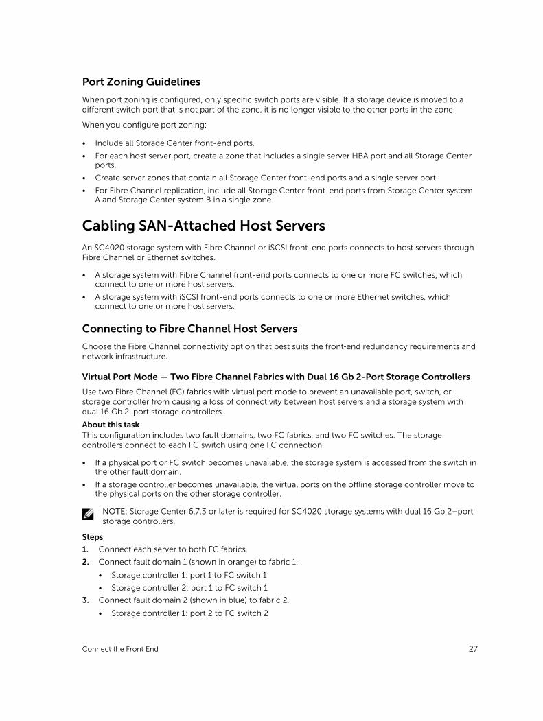
Virtual Port Mode — Two Fibre Channel Fabrics with Dual 16 Gb 2-Port Storage Controllers
Use two Fibre Channel (FC) fabrics with virtual port mode to prevent an unavailable port, switch, or storage controller from causing a loss of connectivity between host servers and a storage system with dual 16 Gb 2-port storage controllers
About this taskThis configuration includes two fault domains, two FC fabrics, and two FC switches. The storage controllers connect to each FC switch using one FC connection.
• If a physical port or FC switch becomes unavailable, the storage system is accessed from the switch in the other fault domain.
• If a storage controller becomes unavailable, the virtual ports on the offline storage controller move to the physical ports on the other storage controller.
NOTE: Storage Center 6.7.3 or later is required for SC4020 storage systems with dual 16 Gb 2–port storage controllers.
Steps
1. Connect each server to both FC fabrics.
2. Connect fault domain 1 (shown in orange) to fabric 1.
• Storage controller 1: port 1 to FC switch 1
• Storage controller 2: port 1 to FC switch 1
3. Connect fault domain 2 (shown in blue) to fabric 2.
• Storage controller 1: port 2 to FC switch 2
Connect the Front End 27
• Storage controller 2: port 2 to FC switch 2
Example
Figure 15. Storage System in Virtual Port Mode with Dual 16 Gb Storage Controllers and Two FC Switches
1. Server 1 2. Server 2
3. FC switch 1 (fault domain 1) 4. FC switch 2 (fault domain 2)
5. Storage system 6. Storage controller 1
7. Storage controller 2
Next stepsInstall or enable MPIO on the host servers.
NOTE: After the Storage Center configuration is complete, run the host access wizard to configure host server access and apply MPIO best practices. For the latest best practices, see the Dell Storage Center Best Practices document on the Dell TechCenter site (http://en.community.dell.com/techcenter/storage/).
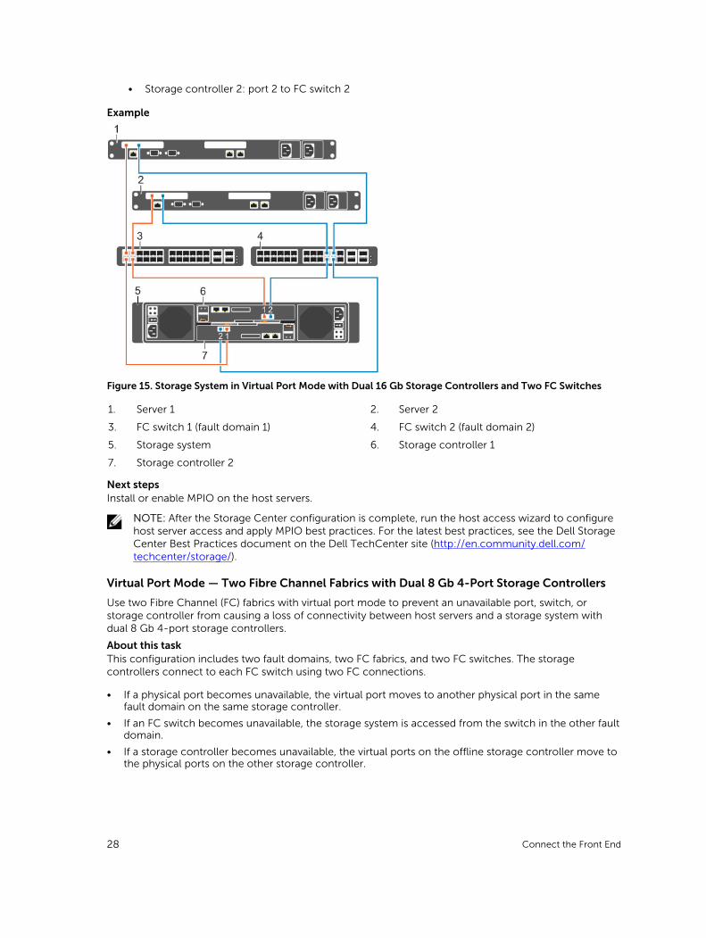
Virtual Port Mode — Two Fibre Channel Fabrics with Dual 8 Gb 4-Port Storage Controllers
Use two Fibre Channel (FC) fabrics with virtual port mode to prevent an unavailable port, switch, or storage controller from causing a loss of connectivity between host servers and a storage system with dual 8 Gb 4-port storage controllers.
About this taskThis configuration includes two fault domains, two FC fabrics, and two FC switches. The storage controllers connect to each FC switch using two FC connections.
• If a physical port becomes unavailable, the virtual port moves to another physical port in the same fault domain on the same storage controller.
• If an FC switch becomes unavailable, the storage system is accessed from the switch in the other fault domain.
• If a storage controller becomes unavailable, the virtual ports on the offline storage controller move to the physical ports on the other storage controller.
28 Connect the Front End
Steps
1. Connect each server to both FC fabrics.
2. Connect fault domain 1 (shown in orange) to fabric 1.
• Storage controller 1: port 1 to FC switch 1
• Storage controller 1: port 3 to FC switch 1
• Storage controller 2: port 1 to FC switch 1
• Storage controller 2: port 3 to FC switch 1
3. Connect fault domain 2 (shown in blue) to fabric 2.
• Storage controller 1: port 2 to FC switch 2
• Storage controller 1: port 4 to FC switch 2
• Storage controller 2: port 2 to FC switch 2
• Storage controller 2: port 4 to FC switch 2
Example
Figure 16. Storage System in Virtual Port Mode with Dual 8 Gb Storage Controllers and Two FC Switches
1. Server 1 2. Server 2
3. FC switch 1 (fault domain 1) 4. FC switch 2 (fault domain 2)
5. Storage system 6. Storage controller 1
7. Storage controller 2
Next stepsInstall or enable MPIO on the host servers.
NOTE: After the Storage Center configuration is complete, run the host access wizard to configure host server access and apply MPIO best practices. For the latest best practices, see the Dell Storage Center Best Practices document on the Dell TechCenter site (http://en.community.dell.com/techcenter/storage/).
Connect the Front End 29
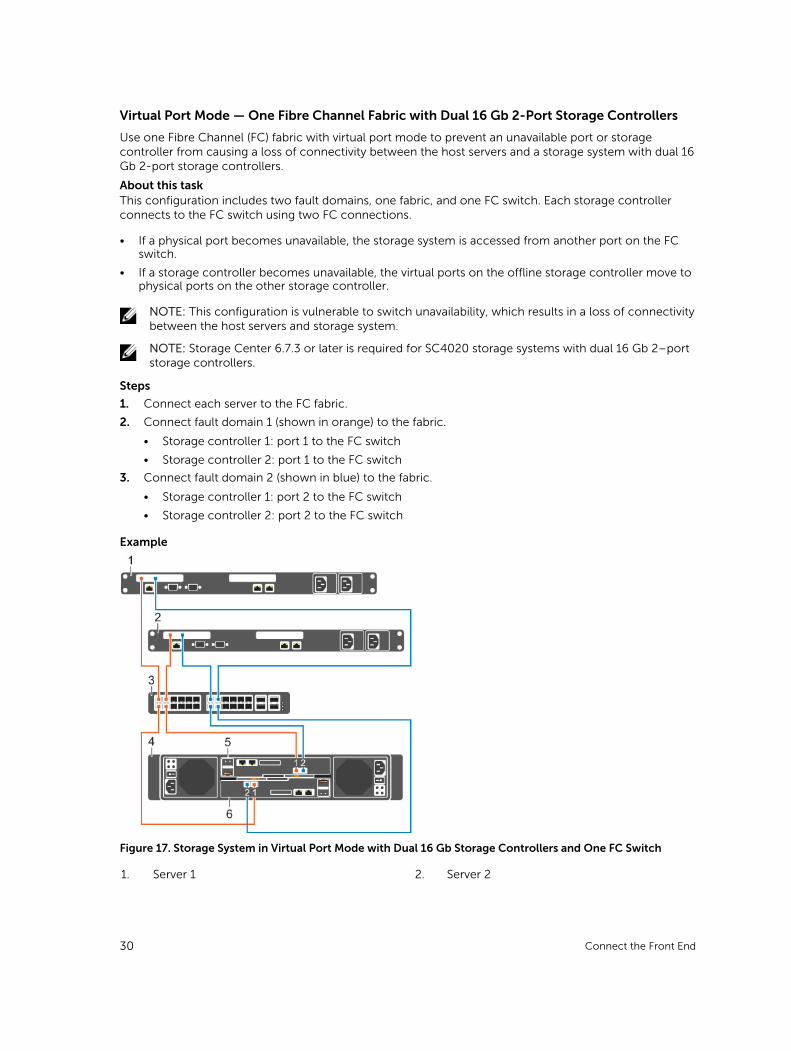
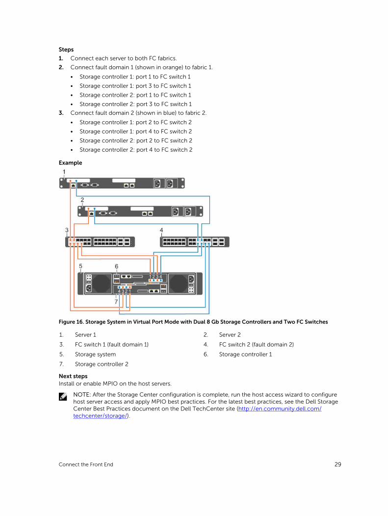
Virtual Port Mode — One Fibre Channel Fabric with Dual 16 Gb 2-Port Storage Controllers
Use one Fibre Channel (FC) fabric with virtual port mode to prevent an unavailable port or storage controller from causing a loss of connectivity between the host servers and a storage system with dual 16 Gb 2-port storage controllers.
About this taskThis configuration includes two fault domains, one fabric, and one FC switch. Each storage controller connects to the FC switch using two FC connections.
• If a physical port becomes unavailable, the storage system is accessed from another port on the FC switch.
• If a storage controller becomes unavailable, the virtual ports on the offline storage controller move to physical ports on the other storage controller.
NOTE: This configuration is vulnerable to switch unavailability, which results in a loss of connectivity between the host servers and storage system.
NOTE: Storage Center 6.7.3 or later is required for SC4020 storage systems with dual 16 Gb 2–port storage controllers.
Steps
1. Connect each server to the FC fabric.
2. Connect fault domain 1 (shown in orange) to the fabric.
• Storage controller 1: port 1 to the FC switch
• Storage controller 2: port 1 to the FC switch
3. Connect fault domain 2 (shown in blue) to the fabric.
• Storage controller 1: port 2 to the FC switch
• Storage controller 2: port 2 to the FC switch
Example
Figure 17. Storage System in Virtual Port Mode with Dual 16 Gb Storage Controllers and One FC Switch
1. Server 1 2. Server 2
30 Connect the Front End
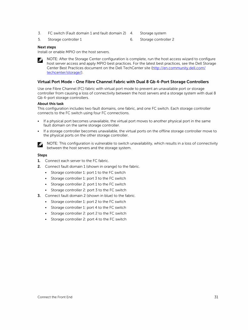
3. FC switch (Fault domain 1 and fault domain 2) 4. Storage system
5. Storage controller 1 6. Storage controller 2
Next stepsInstall or enable MPIO on the host servers.
NOTE: After the Storage Center configuration is complete, run the host access wizard to configure host server access and apply MPIO best practices. For the latest best practices, see the Dell Storage Center Best Practices document on the Dell TechCenter site (http://en.community.dell.com/techcenter/storage/).
Virtual Port Mode - One Fibre Channel Fabric with Dual 8 Gb 4-Port Storage Controllers
Use one Fibre Channel (FC) fabric with virtual port mode to prevent an unavailable port or storage controller from causing a loss of connectivity between the host servers and a storage system with dual 8 Gb 4-port storage controllers.
About this taskThis configuration includes two fault domains, one fabric, and one FC switch. Each storage controller connects to the FC switch using four FC connections.
• If a physical port becomes unavailable, the virtual port moves to another physical port in the same fault domain on the same storage controller.
• If a storage controller becomes unavailable, the virtual ports on the offline storage controller move to the physical ports on the other storage controller.
NOTE: This configuration is vulnerable to switch unavailability, which results in a loss of connectivity between the host servers and the storage system.
Steps
1. Connect each server to the FC fabric.
2. Connect fault domain 1 (shown in orange) to the fabric.
• Storage controller 1: port 1 to the FC switch
• Storage controller 1: port 3 to the FC switch
• Storage controller 2: port 1 to the FC switch
• Storage controller 2: port 3 to the FC switch
3. Connect fault domain 2 (shown in blue) to the fabric.
• Storage controller 1: port 2 to the FC switch
• Storage controller 1: port 4 to the FC switch
• Storage controller 2: port 2 to the FC switch
• Storage controller 2: port 4 to the FC switch
Connect the Front End 31
Example
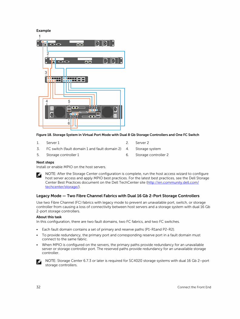
Figure 18. Storage System in Virtual Port Mode with Dual 8 Gb Storage Controllers and One FC Switch
1. Server 1 2. Server 2
3. FC switch (fault domain 1 and fault domain 2) 4. Storage system
5. Storage controller 1 6. Storage controller 2
Next stepsInstall or enable MPIO on the host servers.
NOTE: After the Storage Center configuration is complete, run the host access wizard to configure host server access and apply MPIO best practices. For the latest best practices, see the Dell Storage Center Best Practices document on the Dell TechCenter site (http://en.community.dell.com/techcenter/storage/).
Legacy Mode — Two Fibre Channel Fabrics with Dual 16 Gb 2-Port Storage Controllers
Use two Fibre Channel (FC) fabrics with legacy mode to prevent an unavailable port, switch, or storage controller from causing a loss of connectivity between host servers and a storage system with dual 16 Gb 2-port storage controllers.
About this taskIn this configuration, there are two fault domains, two FC fabrics, and two FC switches.
• Each fault domain contains a set of primary and reserve paths (P1-R1and P2-R2).
• To provide redundancy, the primary port and corresponding reserve port in a fault domain must connect to the same fabric.
• When MPIO is configured on the servers, the primary paths provide redundancy for an unavailable server or storage controller port. The reserved paths provide redundancy for an unavailable storage controller.
NOTE: Storage Center 6.7.3 or later is required for SC4020 storage systems with dual 16 Gb 2–port storage controllers.
32 Connect the Front End
Steps
1. Connect each server to both FC fabrics.
2. Connect fault domain 1 (shown in orange) to fabric 1.
• Primary port P1: Storage controller 1: port 1 to FC switch 1
• Reserved port R1: Storage controller 2: port 1 to FC switch 1
3. Connect fault domain 2 (shown in blue) to fabric 2.
• Primary port P2: Storage controller 2: port 2 to FC switch 2
• Reserved port R2: Storage controller 1: port 2 to FC switch 2
Example
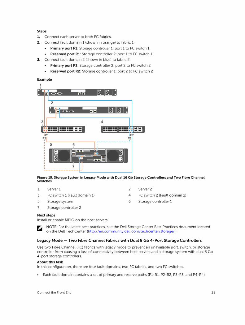
Figure 19. Storage System in Legacy Mode with Dual 16 Gb Storage Controllers and Two Fibre Channel Switches
1. Server 1 2. Server 2
3. FC switch 1 (Fault domain 1) 4. FC switch 2 (Fault domain 2)
5. Storage system 6. Storage controller 1
7. Storage controller 2
Next stepsInstall or enable MPIO on the host servers.
NOTE: For the latest best practices, see the Dell Storage Center Best Practices document located on the Dell TechCenter (http://en.community.dell.com/techcenter/storage/).
Legacy Mode — Two Fibre Channel Fabrics with Dual 8 Gb 4-Port Storage Controllers
Use two Fibre Channel (FC) fabrics with legacy mode to prevent an unavailable port, switch, or storage controller from causing a loss of connectivity between host servers and a storage system with dual 8 Gb 4-port storage controllers.
About this taskIn this configuration, there are four fault domains, two FC fabrics, and two FC switches.
• Each fault domain contains a set of primary and reserve paths (P1-R1, P2-R2, P3-R3, and P4-R4).
Connect the Front End 33
• To provide redundancy, the primary port and corresponding reserve port in a fault domain must connect to the same fabric.
• When MPIO is configured on the servers, the primary paths provide redundancy for an unavailable server or storage controller port. The reserved paths provide redundancy for an unavailable storage controller.
Steps
1. Connect each server to both FC fabrics.
2. Connect fault domain 1 (shown in orange) to fabric 1.
• Primary port P1: Storage controller 1: port 1 to FC switch 1
• Reserved port R1: Storage controller 2: port 1 to FC switch 1
3. Connect fault domain 2 (shown in blue) to fabric 1.
• Primary port P2: Storage controller 2: port 2 to FC switch 1
• Reserved port R2: Storage controller 1: port 2 to FC switch 1
4. Connect fault domain 3 (shown in gray) to fabric 2.
• Primary port P3: Storage controller 1: port 3 to FC switch 2
• Reserved port R3: Storage controller 2: port 3 to FC switch 2
5. Connect fault domain 4 (shown in red) to fabric 2.
• Primary port P4: Storage controller 2: port 4 to FC switch 2
• Reserved port R4: Storage controller 1: port 4 to FC switch 2
Example
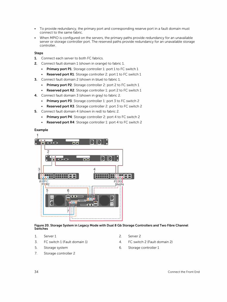
Figure 20. Storage System in Legacy Mode with Dual 8 Gb Storage Controllers and Two Fibre Channel Switches
1. Server 1 2. Server 2
3. FC switch 1 (Fault domain 1) 4. FC switch 2 (Fault domain 2)
5. Storage system 6. Storage controller 1
7. Storage controller 2
34 Connect the Front End
Next stepsInstall or enable MPIO on the host servers.
NOTE: For the latest best practices, see the Dell Storage Center Best Practices document located on the Dell TechCenter (http://en.community.dell.com/techcenter/storage/).
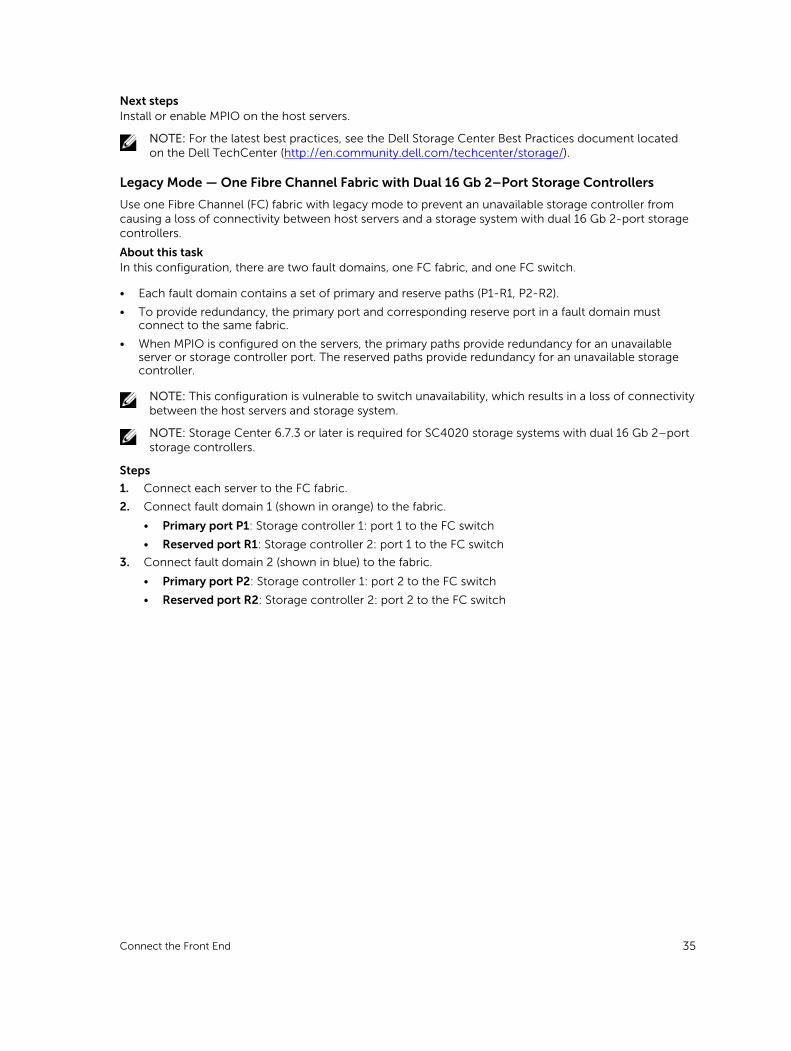
Legacy Mode — One Fibre Channel Fabric with Dual 16 Gb 2–Port Storage Controllers
Use one Fibre Channel (FC) fabric with legacy mode to prevent an unavailable storage controller from causing a loss of connectivity between host servers and a storage system with dual 16 Gb 2-port storage controllers.
About this taskIn this configuration, there are two fault domains, one FC fabric, and one FC switch.
• Each fault domain contains a set of primary and reserve paths (P1-R1, P2-R2).
• To provide redundancy, the primary port and corresponding reserve port in a fault domain must connect to the same fabric.
• When MPIO is configured on the servers, the primary paths provide redundancy for an unavailable server or storage controller port. The reserved paths provide redundancy for an unavailable storage controller.
NOTE: This configuration is vulnerable to switch unavailability, which results in a loss of connectivity between the host servers and storage system.
NOTE: Storage Center 6.7.3 or later is required for SC4020 storage systems with dual 16 Gb 2–port storage controllers.
Steps
1. Connect each server to the FC fabric.
2. Connect fault domain 1 (shown in orange) to the fabric.
• Primary port P1: Storage controller 1: port 1 to the FC switch
• Reserved port R1: Storage controller 2: port 1 to the FC switch
3. Connect fault domain 2 (shown in blue) to the fabric.
• Primary port P2: Storage controller 1: port 2 to the FC switch
• Reserved port R2: Storage controller 2: port 2 to the FC switch
Connect the Front End 35
Example
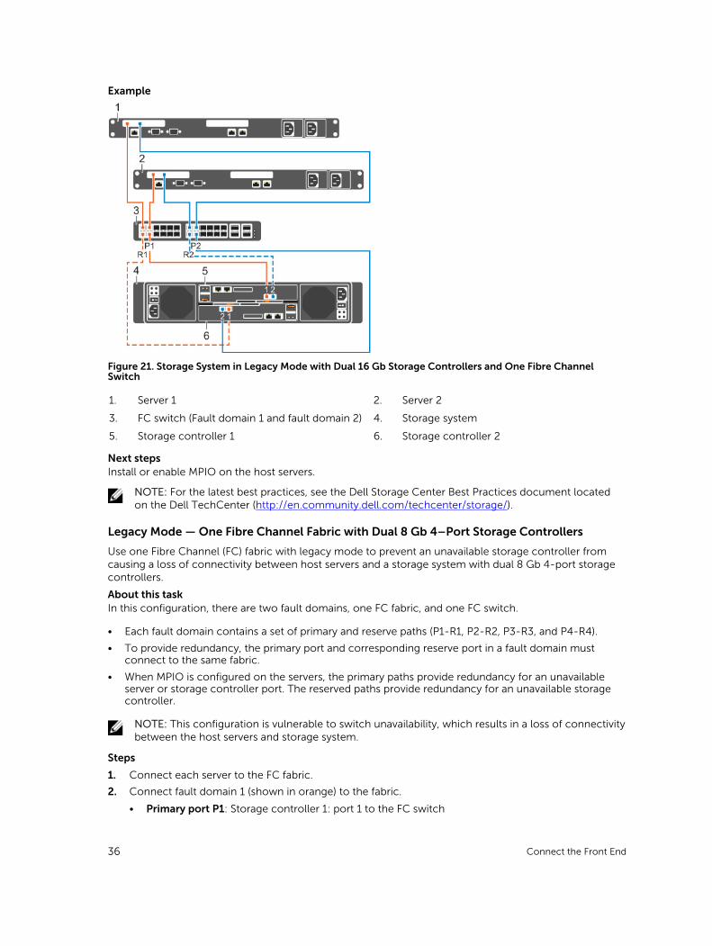
Figure 21. Storage System in Legacy Mode with Dual 16 Gb Storage Controllers and One Fibre Channel Switch
1. Server 1 2. Server 2
3. FC switch (Fault domain 1 and fault domain 2) 4. Storage system
5. Storage controller 1 6. Storage controller 2
Next stepsInstall or enable MPIO on the host servers.
NOTE: For the latest best practices, see the Dell Storage Center Best Practices document located on the Dell TechCenter (http://en.community.dell.com/techcenter/storage/).
Legacy Mode — One Fibre Channel Fabric with Dual 8 Gb 4–Port Storage Controllers
Use one Fibre Channel (FC) fabric with legacy mode to prevent an unavailable storage controller from causing a loss of connectivity between host servers and a storage system with dual 8 Gb 4-port storage controllers.
About this taskIn this configuration, there are two fault domains, one FC fabric, and one FC switch.
• Each fault domain contains a set of primary and reserve paths (P1-R1, P2-R2, P3-R3, and P4-R4).
• To provide redundancy, the primary port and corresponding reserve port in a fault domain must connect to the same fabric.
• When MPIO is configured on the servers, the primary paths provide redundancy for an unavailable server or storage controller port. The reserved paths provide redundancy for an unavailable storage controller.
NOTE: This configuration is vulnerable to switch unavailability, which results in a loss of connectivity between the host servers and storage system.
Steps
1. Connect each server to the FC fabric.
2. Connect fault domain 1 (shown in orange) to the fabric.
• Primary port P1: Storage controller 1: port 1 to the FC switch
36 Connect the Front End
• Reserved port R1: Storage controller 2: port 1 to the FC switch
3. Connect fault domain 2 (shown in blue) to the fabric.
• Primary port P2: Storage controller 1: port 2 to the FC switch
• Reserved port R2: Storage controller 2: port 2 to the FC switch
4. Connect fault domain 3 (shown in gray) to the fabric.
• Primary port P3: Storage controller 1: port 3 to FC switch
• Reserved port R3: Storage controller 2: port 3 to FC switch
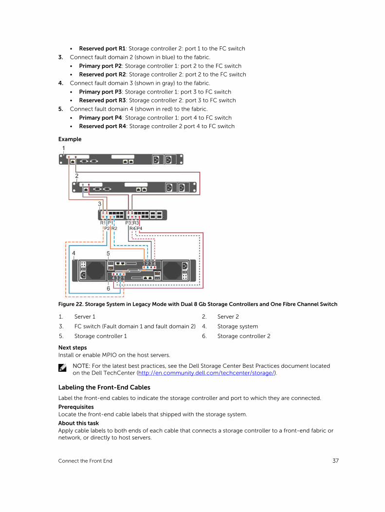
5. Connect fault domain 4 (shown in red) to the fabric.
• Primary port P4: Storage controller 1: port 4 to FC switch
• Reserved port R4: Storage controller 2 port 4 to FC switch
Example
Figure 22. Storage System in Legacy Mode with Dual 8 Gb Storage Controllers and One Fibre Channel Switch
1. Server 1 2. Server 2
3. FC switch (Fault domain 1 and fault domain 2) 4. Storage system
5. Storage controller 1 6. Storage controller 2
Next stepsInstall or enable MPIO on the host servers.
NOTE: For the latest best practices, see the Dell Storage Center Best Practices document located on the Dell TechCenter (http://en.community.dell.com/techcenter/storage/).
Labeling the Front-End Cables
Label the front-end cables to indicate the storage controller and port to which they are connected.
PrerequisitesLocate the front-end cable labels that shipped with the storage system.
About this taskApply cable labels to both ends of each cable that connects a storage controller to a front-end fabric or network, or directly to host servers.
Connect the Front End 37
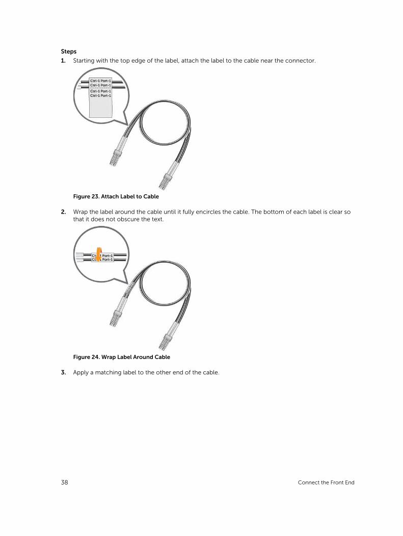
Steps
1. Starting with the top edge of the label, attach the label to the cable near the connector.
Figure 23. Attach Label to Cable
2. Wrap the label around the cable until it fully encircles the cable. The bottom of each label is clear so that it does not obscure the text.
Figure 24. Wrap Label Around Cable
3. Apply a matching label to the other end of the cable.
38 Connect the Front End
Connecting to iSCSI Host Servers
Choose the iSCSI connectivity option that best suits the front‐end redundancy requirements and network infrastructure.
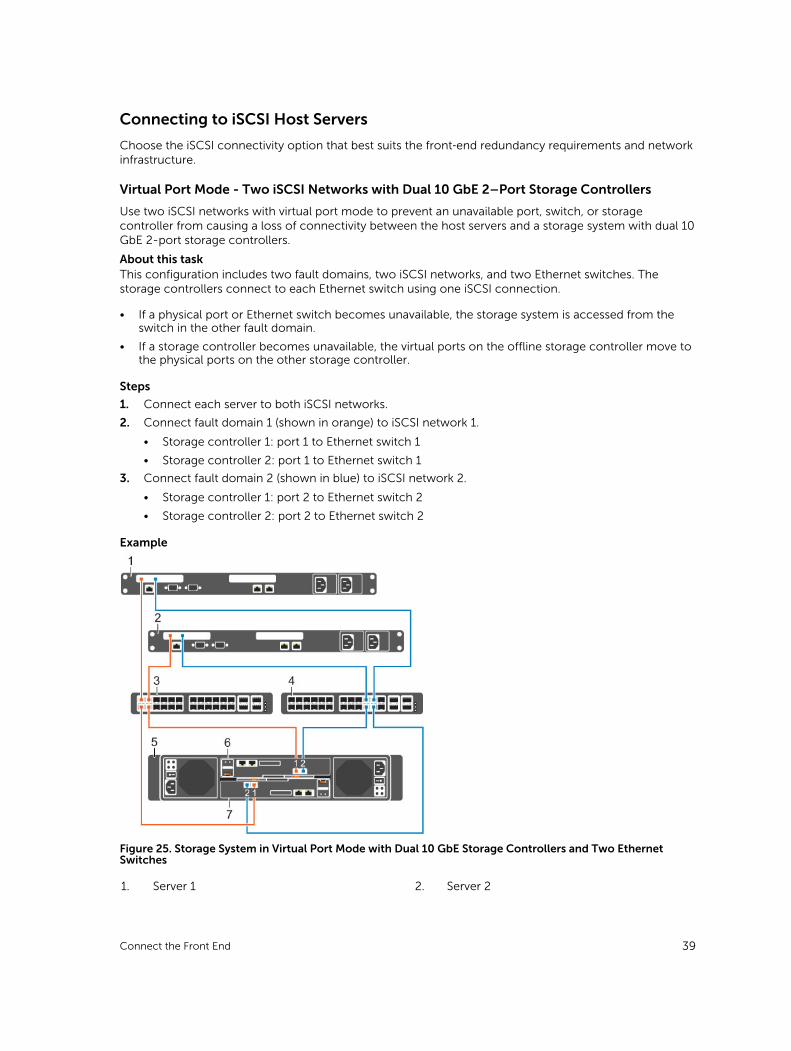
Virtual Port Mode - Two iSCSI Networks with Dual 10 GbE 2–Port Storage Controllers
Use two iSCSI networks with virtual port mode to prevent an unavailable port, switch, or storage controller from causing a loss of connectivity between the host servers and a storage system with dual 10 GbE 2-port storage controllers.
About this taskThis configuration includes two fault domains, two iSCSI networks, and two Ethernet switches. The storage controllers connect to each Ethernet switch using one iSCSI connection.
• If a physical port or Ethernet switch becomes unavailable, the storage system is accessed from the switch in the other fault domain.
• If a storage controller becomes unavailable, the virtual ports on the offline storage controller move to the physical ports on the other storage controller.
Steps
1. Connect each server to both iSCSI networks.
2. Connect fault domain 1 (shown in orange) to iSCSI network 1.
• Storage controller 1: port 1 to Ethernet switch 1
• Storage controller 2: port 1 to Ethernet switch 1
3. Connect fault domain 2 (shown in blue) to iSCSI network 2.
• Storage controller 1: port 2 to Ethernet switch 2
• Storage controller 2: port 2 to Ethernet switch 2
Example
Figure 25. Storage System in Virtual Port Mode with Dual 10 GbE Storage Controllers and Two Ethernet Switches
1. Server 1 2. Server 2
Connect the Front End 39

3. Ethernet switch 1 (fault domain 1) 4. Ethernet switch 2 (fault domain 2)
5. Storage system 6. Storage controller 1
7. Storage controller 2
Next stepsInstall or enable MPIO on the host servers.
NOTE: For the latest best practices, see the Dell Storage Center Best Practices document on the Dell TechCenter site (http://en.community.dell.com/techcenter/storage/).
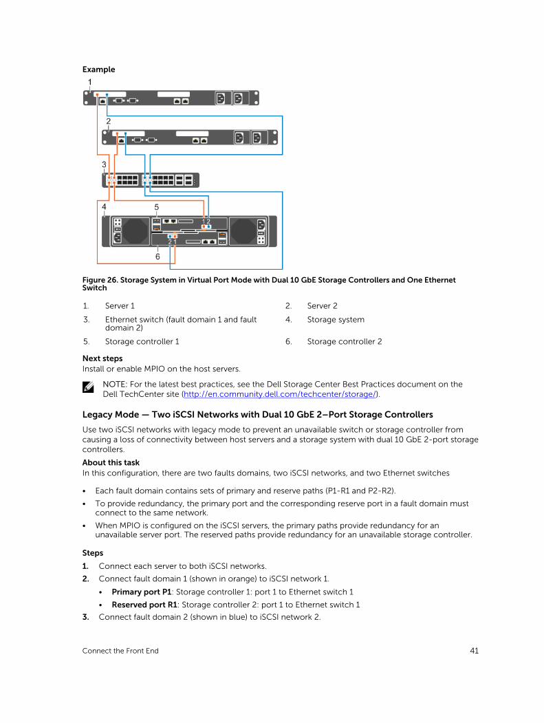
Virtual Port Mode — One iSCSI Network with Dual 10 GbE 2-Port Storage Controllers
Use one iSCSI network with virtual port mode to prevent an unavailable port or storage controller from causing a loss of connectivity between the host servers and a storage system with dual 10 GbE 2-Port storage controllers.
About this taskThis configuration includes two fault domains, one iSCSI network, and one Ethernet switch. Each storage controller connects to the Ethernet switch using two iSCSI connections.
• If a physical port becomes unavailable, the storage system is accessed from another port on the Ethernet switch.
• If a storage controller becomes unavailable, the virtual ports on the offline storage controller move to the physical ports on the other storage controller.
NOTE: This configuration is vulnerable to switch unavailability, which results in a loss of connectivity between the host servers and storage system.
Steps
1. Connect each server to the iSCSI network.
2. Connect fault domain 1 (shown in orange) to the iSCSI network.
• Storage controller 1: port 1 to the Ethernet switch
• Storage controller 2: port 1 to the Ethernet switch
3. Connect fault domain 2 (shown in blue) to the iSCSI network.
• Storage controller 1: port 2 to the Ethernet switch
• Storage controller 2: port 2 to the Ethernet switch
40 Connect the Front End
Example
Figure 26. Storage System in Virtual Port Mode with Dual 10 GbE Storage Controllers and One Ethernet Switch
1. Server 1 2. Server 2
3. Ethernet switch (fault domain 1 and fault domain 2)
4. Storage system
5. Storage controller 1 6. Storage controller 2
Next stepsInstall or enable MPIO on the host servers.
NOTE: For the latest best practices, see the Dell Storage Center Best Practices document on the Dell TechCenter site (http://en.community.dell.com/techcenter/storage/).
Legacy Mode — Two iSCSI Networks with Dual 10 GbE 2–Port Storage Controllers
Use two iSCSI networks with legacy mode to prevent an unavailable switch or storage controller from causing a loss of connectivity between host servers and a storage system with dual 10 GbE 2-port storage controllers.
About this taskIn this configuration, there are two faults domains, two iSCSI networks, and two Ethernet switches
• Each fault domain contains sets of primary and reserve paths (P1-R1 and P2-R2).
• To provide redundancy, the primary port and the corresponding reserve port in a fault domain must connect to the same network.
• When MPIO is configured on the iSCSI servers, the primary paths provide redundancy for an unavailable server port. The reserved paths provide redundancy for an unavailable storage controller.
Steps
1. Connect each server to both iSCSI networks.
2. Connect fault domain 1 (shown in orange) to iSCSI network 1.
• Primary port P1: Storage controller 1: port 1 to Ethernet switch 1
• Reserved port R1: Storage controller 2: port 1 to Ethernet switch 1
3. Connect fault domain 2 (shown in blue) to iSCSI network 2.
Connect the Front End 41
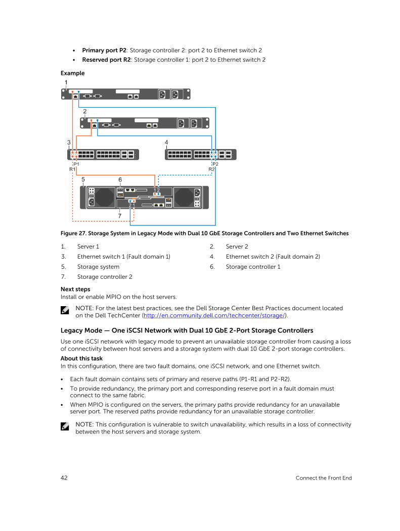
• Primary port P2: Storage controller 2: port 2 to Ethernet switch 2
• Reserved port R2: Storage controller 1: port 2 to Ethernet switch 2
Example
Figure 27. Storage System in Legacy Mode with Dual 10 GbE Storage Controllers and Two Ethernet Switches
1. Server 1 2. Server 2
3. Ethernet switch 1 (Fault domain 1) 4. Ethernet switch 2 (Fault domain 2)
5. Storage system 6. Storage controller 1
7. Storage controller 2
Next stepsInstall or enable MPIO on the host servers.
NOTE: For the latest best practices, see the Dell Storage Center Best Practices document located on the Dell TechCenter (http://en.community.dell.com/techcenter/storage/).
Legacy Mode — One iSCSI Network with Dual 10 GbE 2-Port Storage Controllers
Use one iSCSI network with legacy mode to prevent an unavailable storage controller from causing a loss of connectivity between host servers and a storage system with dual 10 GbE 2-port storage controllers.
About this taskIn this configuration, there are two fault domains, one iSCSI network, and one Ethernet switch.
• Each fault domain contains sets of primary and reserve paths (P1-R1 and P2-R2).
• To provide redundancy, the primary port and corresponding reserve port in a fault domain must connect to the same fabric.
• When MPIO is configured on the servers, the primary paths provide redundancy for an unavailable server port. The reserved paths provide redundancy for an unavailable storage controller.
NOTE: This configuration is vulnerable to switch unavailability, which results in a loss of connectivity between the host servers and storage system.
42 Connect the Front End
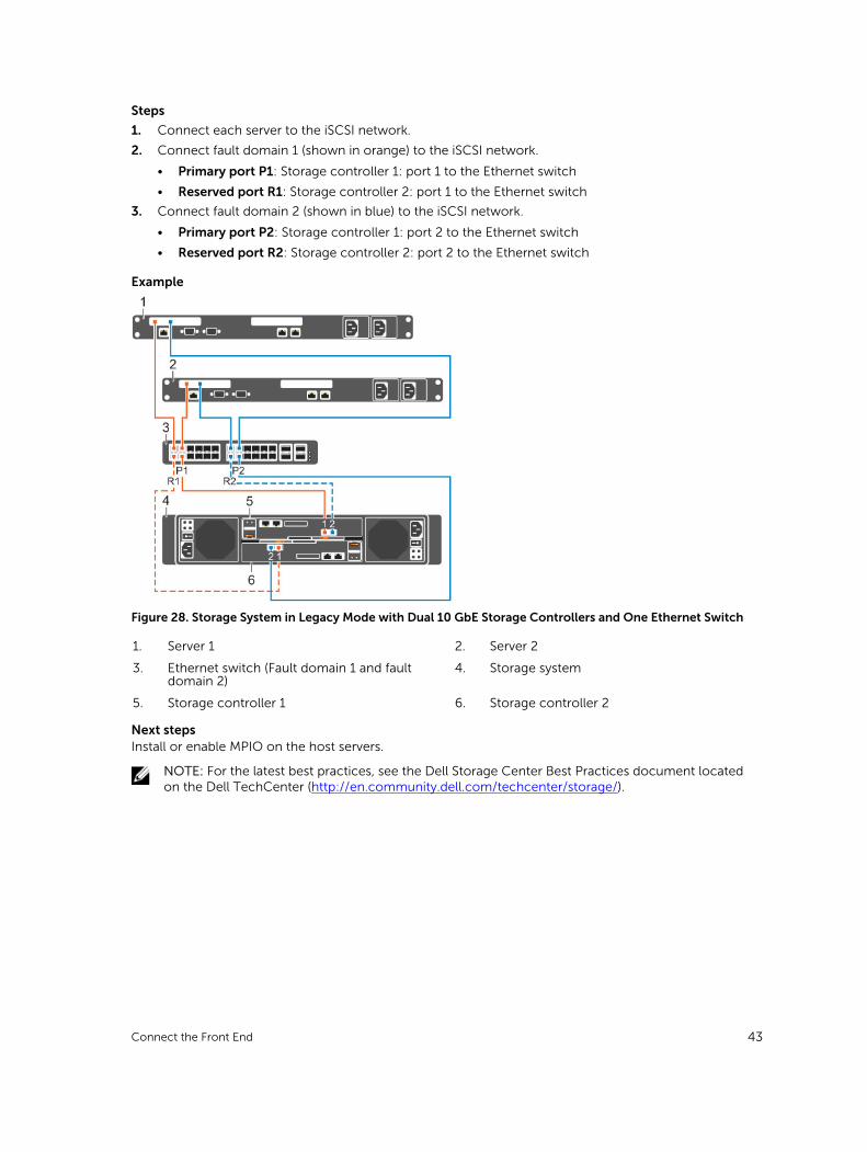
Steps
1. Connect each server to the iSCSI network.
2. Connect fault domain 1 (shown in orange) to the iSCSI network.
• Primary port P1: Storage controller 1: port 1 to the Ethernet switch
• Reserved port R1: Storage controller 2: port 1 to the Ethernet switch
3. Connect fault domain 2 (shown in blue) to the iSCSI network.
• Primary port P2: Storage controller 1: port 2 to the Ethernet switch
• Reserved port R2: Storage controller 2: port 2 to the Ethernet switch
Example
Figure 28. Storage System in Legacy Mode with Dual 10 GbE Storage Controllers and One Ethernet Switch
1. Server 1 2. Server 2
3. Ethernet switch (Fault domain 1 and fault domain 2)
4. Storage system
5. Storage controller 1 6. Storage controller 2
Next stepsInstall or enable MPIO on the host servers.
NOTE: For the latest best practices, see the Dell Storage Center Best Practices document located on the Dell TechCenter (http://en.community.dell.com/techcenter/storage/).
Connect the Front End 43
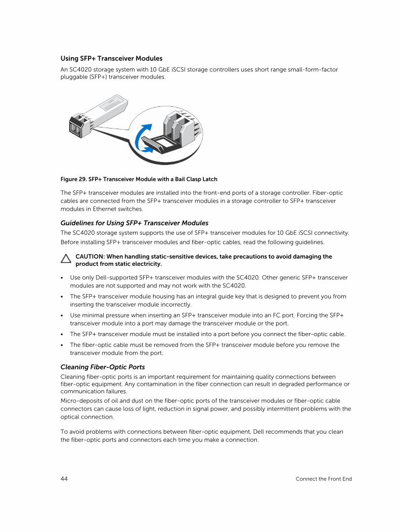
Using SFP+ Transceiver Modules
An SC4020 storage system with 10 GbE iSCSI storage controllers uses short range small-form-factor pluggable (SFP+) transceiver modules.
Figure 29. SFP+ Transceiver Module with a Bail Clasp Latch
The SFP+ transceiver modules are installed into the front-end ports of a storage controller. Fiber-optic cables are connected from the SFP+ transceiver modules in a storage controller to SFP+ transceiver modules in Ethernet switches.
Guidelines for Using SFP+ Transceiver Modules
The SC4020 storage system supports the use of SFP+ transceiver modules for 10 GbE iSCSI connectivity.
Before installing SFP+ transceiver modules and fiber-optic cables, read the following guidelines.
CAUTION: When handling static-sensitive devices, take precautions to avoid damaging the product from static electricity.
• Use only Dell-supported SFP+ transceiver modules with the SC4020. Other generic SFP+ transceiver modules are not supported and may not work with the SC4020.
• The SFP+ transceiver module housing has an integral guide key that is designed to prevent you from inserting the transceiver module incorrectly.
• Use minimal pressure when inserting an SFP+ transceiver module into an FC port. Forcing the SFP+ transceiver module into a port may damage the transceiver module or the port.
• The SFP+ transceiver module must be installed into a port before you connect the fiber-optic cable.
• The fiber-optic cable must be removed from the SFP+ transceiver module before you remove the transceiver module from the port.
Cleaning Fiber-Optic Ports
Cleaning fiber-optic ports is an important requirement for maintaining quality connections between fiber-optic equipment. Any contamination in the fiber connection can result in degraded performance or communication failures.
Micro-deposits of oil and dust on the fiber-optic ports of the transceiver modules or fiber-optic cable connectors can cause loss of light, reduction in signal power, and possibly intermittent problems with the optical connection.
To avoid problems with connections between fiber-optic equipment, Dell recommends that you clean the fiber-optic ports and connectors each time you make a connection.
44 Connect the Front End
NOTE: When you are not using a transceiver module or fiber-optic cable, always install protective covers to prevent contamination.
Cleaning SFP+ Transceiver ModulesDell recommends using a can of compressed air to clean the fiber-optic ports of SFP+ transceiver modules.
Prerequisites
• Handle the SFP+ transceiver module in an ESD safe environment using the proper safety precautions.
• Make sure that the can of compressed air is approved for cleaning fiber optics.
• Make sure that the can of compressed air has a straw inserted into the nozzle.
Steps
1. Spray the can of compressed air for 3–5 seconds to make sure that any liquid propellant is expelled from the straw.
2. Align a fiber-optic port of the transceiver module with the straw on the can of compressed air.
Hold the transceiver module near the end of the straw, but do not touch the inner surfaces of the module.
3. Hold the can of compressed air upright and level with the transceiver module.
CAUTION: Tipping the can of compressed air may release liquids in the air stream.
4. Use the can of compressed air to blow out particles from the inside of the transceiver module.
5. Examine the optical surface of the connector using high intensity light and a magnifying tool.
If contaminants still exist, repeat the cleaning process.
6. Immediately install the protective dust cover into the transceiver module to avoid recontamination.
Keep the protective cover in the transceiver module until you are ready to connect it to a fiber optic cable.
Cleaning Fiber-Optic Cable ConnectorsDell recommends using a can of compressed air, methanol or isopropyl alcohol, and a lens tissue to clean fiber-optic cable connectors.
Prerequisites
• Do not allow the end of the fiber-optic cable to contact any surface, including your fingers.
• Make sure that the can of compressed air is approved for cleaning fiber optics
• Make sure that the can of compressed air has a straw inserted into the nozzle.
• Only use fresh (dry) spectroscopic grade methanol or isopropyl alcohol as a cleaning solvent.
• Only use lens tissues with long fibers and a low ash content type that has no chemical additives.
Steps
1. Spray the can of compressed air for 3–5 seconds to make sure that any liquid propellant is expelled from the straw.
2. Hold the can of compressed air upright and level with the fiber-optic cable connector.
CAUTION: Tipping the can of compressed air may release liquids in the air stream.
3. Use the can of compressed air to blow particles off the surface of the fiber-optic cable connector.
4. Place 2–3 drops of the methanol or isopropyl alcohol on a lens tissue.
5. Place the wet portion of the lens tissue on the optical surface of the fiber-optic cable connector and slowly drag it across.
6. Examine the optical surface of the fiber-optic cable connector using high intensity light and a magnifying tool.
Connect the Front End 45
If streaks or contaminants still exist, repeat the cleaning process using a fresh lens tissue.
7. Immediately install the protective dust cover over the end of the cable to avoid recontamination.
Keep the protective cover on the end of the cable until you are ready to connect it.
Install an SFP+ Transceiver Module
Complete the following steps to install an SFP+ transceiver module in a 10 GbE iSCSI storage controller.
About this taskRead the following cautions and information before installing an SFP+ transceiver module.
WARNING: To reduce the risk of injury from laser radiation or damage to the equipment, observe the following precautions:
• Do not open any panels, operate controls, make adjustments, or perform procedures to a laser device other than those specified in this document.
• Do not stare into the laser beam.
CAUTION: Transceiver modules can be damaged by electrostatic discharge (ESD). To prevent ESD damage to the transceiver module, take the following precautions:
• Wear an antistatic discharge strap while handling transceiver modules.
• Place transceiver modules in antistatic packing material when transporting or storing them.
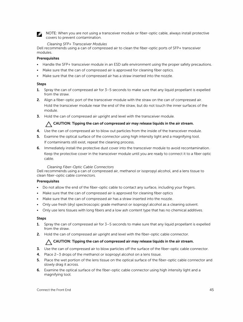
Steps
1. Position the transceiver module so that the key is oriented correctly to the port in the storage controller.
Figure 30. Install the SFP+ Transceiver Module
1. SFP+ transceiver module 2. Fiber-optic cable connector
2. Insert the transceiver module into the port until it is firmly seated and the latching mechanism clicks.
The transceiver modules are keyed so that they can only be inserted with the correct orientation. If a transceiver module does not slide in easily, ensure that it is correctly oriented.
CAUTION: To reduce the risk of damage to the equipment, do not use excessive force when inserting the transceiver module.
3. Position fiber-optic cable so that the key (the ridge on one side of the cable connector) is aligned with the slot in the transceiver module.
CAUTION: Touching the end of a fiber-optic cable damages the cable. Whenever a fiber-optic cable is not connected, replace the protective covers on the ends of the cable.
46 Connect the Front End
4. Insert the fiber-optic cable into the transceiver module until the latching mechanism clicks.
5. Insert the other end of the fiber-optic cable into the SFP+ transceiver module of an Ethernet switch.
Remove an SFP+ Transceiver Module
Complete the following steps to remove an SFP+ transceiver module from a 10 GbE iSCSI storage controller.
PrerequisitesUse failover testing to make sure that the connection between host servers and the Storage Center remains up if the port is disconnected.
About this taskRead the following cautions and information before beginning removal or replacement procedures.
WARNING: To reduce the risk of injury from laser radiation or damage to the equipment, observe the following precautions.
• Do not open any panels, operate controls, make adjustments, or perform procedures to a laser device other than those specified in this document.
• Do not stare into the laser beam.
CAUTION: Transceiver modules can be damaged by electrostatic discharge (ESD). To prevent ESD damage to the transceiver module, take the following precautions:
• Wear an antistatic discharge strap while handling modules.
• Place modules in antistatic packing material when transporting or storing them.
Steps
1. Remove the fiber-optic cable that is inserted into the transceiver.
a. Make certain the fiber-optic cable is labeled before removing it.
b. Press the release clip on the bottom of the cable connector to remove the fiber-optic cable from the transceiver.
CAUTION: Touching the end of a fiber-optic cable damages the cable. Whenever a fiber-optic cable is not connected, replace the protective covers on the ends of the cables.
2. Open the transceiver module latching mechanism.
3. Grasp the bail clasp latch on the transceiver module and pull the latch out and down to eject the transceiver module from the socket.
4. Slide the transceiver module out of the port.
Connect the Front End 47
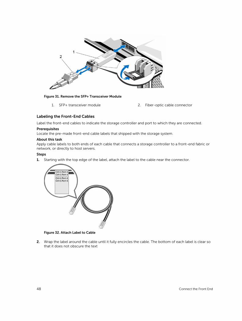
Figure 31. Remove the SFP+ Transceiver Module
1. SFP+ transceiver module 2. Fiber-optic cable connector
Labeling the Front-End Cables
Label the front-end cables to indicate the storage controller and port to which they are connected.
PrerequisitesLocate the pre-made front-end cable labels that shipped with the storage system.
About this taskApply cable labels to both ends of each cable that connects a storage controller to a front-end fabric or network, or directly to host servers.
Steps
1. Starting with the top edge of the label, attach the label to the cable near the connector.
Figure 32. Attach Label to Cable
2. Wrap the label around the cable until it fully encircles the cable. The bottom of each label is clear so that it does not obscure the text
48 Connect the Front End
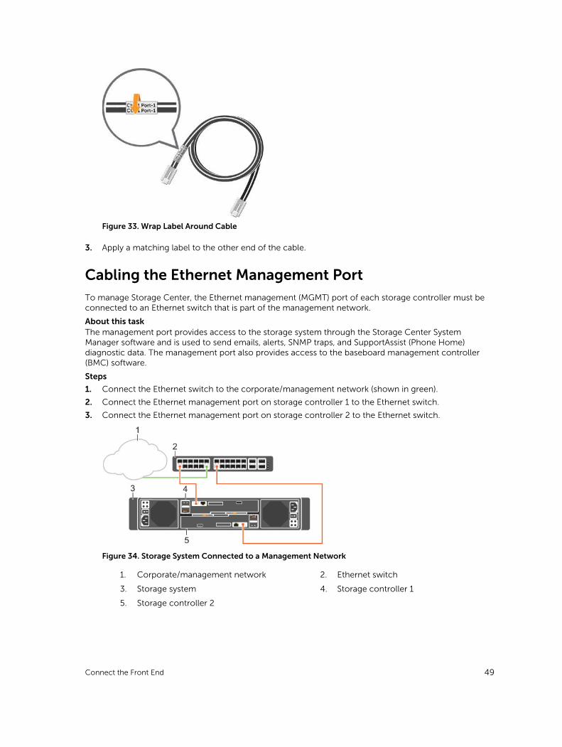
Figure 33. Wrap Label Around Cable
3. Apply a matching label to the other end of the cable.
Cabling the Ethernet Management PortTo manage Storage Center, the Ethernet management (MGMT) port of each storage controller must be connected to an Ethernet switch that is part of the management network.
About this taskThe management port provides access to the storage system through the Storage Center System Manager software and is used to send emails, alerts, SNMP traps, and SupportAssist (Phone Home) diagnostic data. The management port also provides access to the baseboard management controller (BMC) software.
Steps
1. Connect the Ethernet switch to the corporate/management network (shown in green).
2. Connect the Ethernet management port on storage controller 1 to the Ethernet switch.
3. Connect the Ethernet management port on storage controller 2 to the Ethernet switch.
Figure 34. Storage System Connected to a Management Network
1. Corporate/management network 2. Ethernet switch
3. Storage system 4. Storage controller 1
5. Storage controller 2
Connect the Front End 49
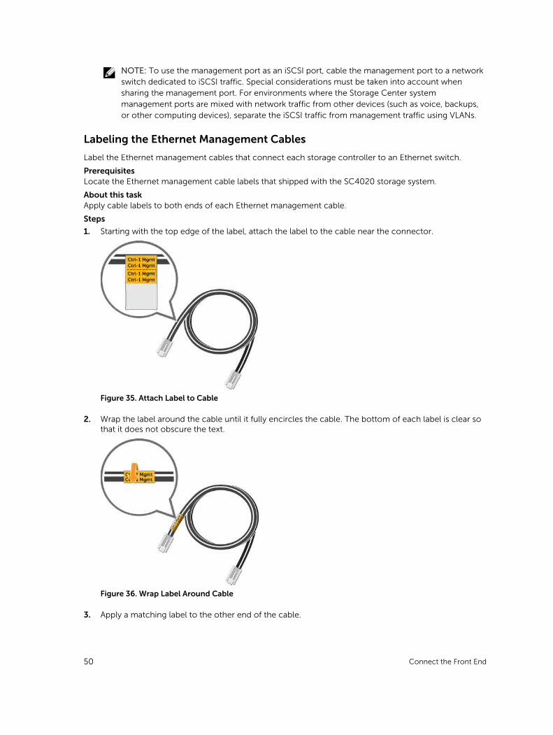
NOTE: To use the management port as an iSCSI port, cable the management port to a network switch dedicated to iSCSI traffic. Special considerations must be taken into account when sharing the management port. For environments where the Storage Center system management ports are mixed with network traffic from other devices (such as voice, backups, or other computing devices), separate the iSCSI traffic from management traffic using VLANs.
Labeling the Ethernet Management Cables
Label the Ethernet management cables that connect each storage controller to an Ethernet switch.
PrerequisitesLocate the Ethernet management cable labels that shipped with the SC4020 storage system.
About this taskApply cable labels to both ends of each Ethernet management cable.
Steps
1. Starting with the top edge of the label, attach the label to the cable near the connector.
Figure 35. Attach Label to Cable
2. Wrap the label around the cable until it fully encircles the cable. The bottom of each label is clear so that it does not obscure the text.
Figure 36. Wrap Label Around Cable
3. Apply a matching label to the other end of the cable.
50 Connect the Front End
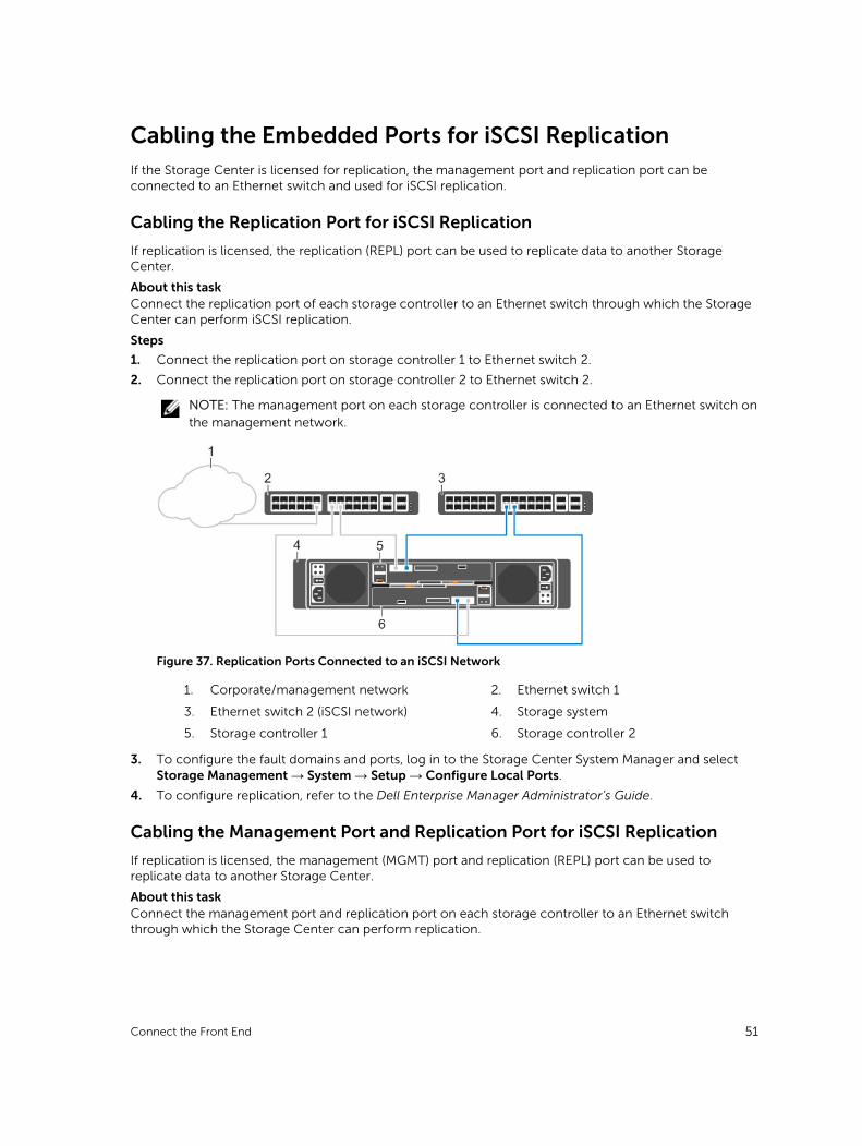
Cabling the Embedded Ports for iSCSI ReplicationIf the Storage Center is licensed for replication, the management port and replication port can be connected to an Ethernet switch and used for iSCSI replication.
Cabling the Replication Port for iSCSI Replication
If replication is licensed, the replication (REPL) port can be used to replicate data to another Storage Center.
About this taskConnect the replication port of each storage controller to an Ethernet switch through which the Storage Center can perform iSCSI replication.
Steps
1. Connect the replication port on storage controller 1 to Ethernet switch 2.
2. Connect the replication port on storage controller 2 to Ethernet switch 2.
NOTE: The management port on each storage controller is connected to an Ethernet switch on the management network.
Figure 37. Replication Ports Connected to an iSCSI Network
1. Corporate/management network 2. Ethernet switch 1
3. Ethernet switch 2 (iSCSI network) 4. Storage system
5. Storage controller 1 6. Storage controller 2
3. To configure the fault domains and ports, log in to the Storage Center System Manager and select Storage Management → System → Setup → Configure Local Ports.
4. To configure replication, refer to the Dell Enterprise Manager Administrator’s Guide.
Cabling the Management Port and Replication Port for iSCSI Replication
If replication is licensed, the management (MGMT) port and replication (REPL) port can be used to replicate data to another Storage Center.
About this taskConnect the management port and replication port on each storage controller to an Ethernet switch through which the Storage Center can perform replication.
Connect the Front End 51
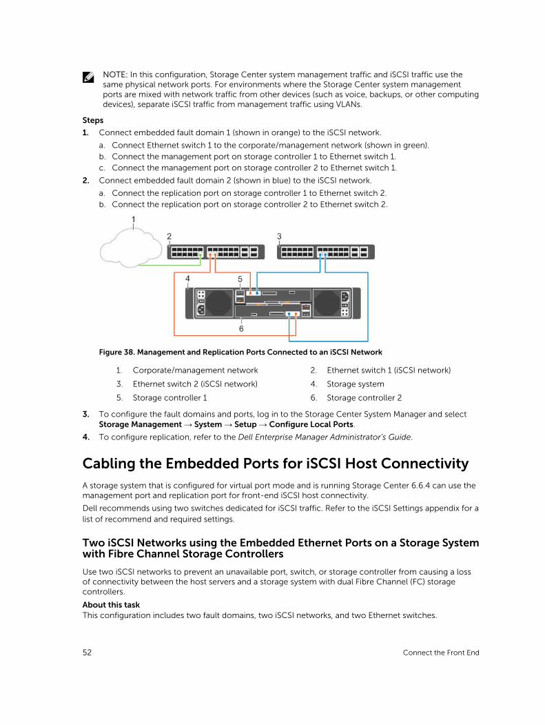
NOTE: In this configuration, Storage Center system management traffic and iSCSI traffic use the same physical network ports. For environments where the Storage Center system management ports are mixed with network traffic from other devices (such as voice, backups, or other computing devices), separate iSCSI traffic from management traffic using VLANs.
Steps
1. Connect embedded fault domain 1 (shown in orange) to the iSCSI network.
a. Connect Ethernet switch 1 to the corporate/management network (shown in green).
b. Connect the management port on storage controller 1 to Ethernet switch 1.
c. Connect the management port on storage controller 2 to Ethernet switch 1.
2. Connect embedded fault domain 2 (shown in blue) to the iSCSI network.
a. Connect the replication port on storage controller 1 to Ethernet switch 2.
b. Connect the replication port on storage controller 2 to Ethernet switch 2.
Figure 38. Management and Replication Ports Connected to an iSCSI Network
1. Corporate/management network 2. Ethernet switch 1 (iSCSI network)
3. Ethernet switch 2 (iSCSI network) 4. Storage system
5. Storage controller 1 6. Storage controller 2
3. To configure the fault domains and ports, log in to the Storage Center System Manager and select Storage Management → System → Setup → Configure Local Ports.
4. To configure replication, refer to the Dell Enterprise Manager Administrator’s Guide.
Cabling the Embedded Ports for iSCSI Host ConnectivityA storage system that is configured for virtual port mode and is running Storage Center 6.6.4 can use the management port and replication port for front-end iSCSI host connectivity.
Dell recommends using two switches dedicated for iSCSI traffic. Refer to the iSCSI Settings appendix for a list of recommend and required settings.
Two iSCSI Networks using the Embedded Ethernet Ports on a Storage System with Fibre Channel Storage Controllers
Use two iSCSI networks to prevent an unavailable port, switch, or storage controller from causing a loss of connectivity between the host servers and a storage system with dual Fibre Channel (FC) storage controllers.
About this taskThis configuration includes two fault domains, two iSCSI networks, and two Ethernet switches.
52 Connect the Front End
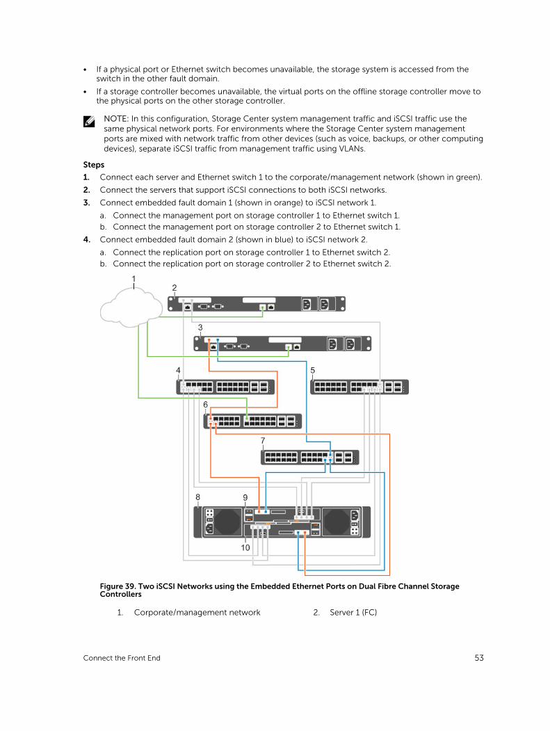
• If a physical port or Ethernet switch becomes unavailable, the storage system is accessed from the switch in the other fault domain.
• If a storage controller becomes unavailable, the virtual ports on the offline storage controller move to the physical ports on the other storage controller.
NOTE: In this configuration, Storage Center system management traffic and iSCSI traffic use the same physical network ports. For environments where the Storage Center system management ports are mixed with network traffic from other devices (such as voice, backups, or other computing devices), separate iSCSI traffic from management traffic using VLANs.
Steps
1. Connect each server and Ethernet switch 1 to the corporate/management network (shown in green).
2. Connect the servers that support iSCSI connections to both iSCSI networks.
3. Connect embedded fault domain 1 (shown in orange) to iSCSI network 1.
a. Connect the management port on storage controller 1 to Ethernet switch 1.
b. Connect the management port on storage controller 2 to Ethernet switch 1.
4. Connect embedded fault domain 2 (shown in blue) to iSCSI network 2.
a. Connect the replication port on storage controller 1 to Ethernet switch 2.
b. Connect the replication port on storage controller 2 to Ethernet switch 2.
Figure 39. Two iSCSI Networks using the Embedded Ethernet Ports on Dual Fibre Channel Storage Controllers
1. Corporate/management network 2. Server 1 (FC)
Connect the Front End 53
3. Server 2 (iSCSI) 4. FC Switch 1 (fault domain 1 for FC fabric)
5. FC Switch 2 (fault domain 2 for FC fabric) 6. Ethernet switch 1 (fault domain 1)
7. Ethernet switch 2 (fault domain 2) 8. Storage system
9. Storage controller 1 10. Storage controller 2
5. To configure the fault domains and ports, log in to the Storage Center System Manager and select Storage Management → System → Setup → Configure Local Ports.
Next stepsInstall or enable MPIO on the host servers.
NOTE: For the latest best practices, see the Dell Storage Center Best Practices document on the Dell TechCenter site (http://en.community.dell.com/techcenter/storage/).
Two iSCSI Networks Using the Embedded Ethernet Ports on a Storage System with iSCSI Storage Controllers
Use two iSCSI networks to prevent an unavailable port, switch or storage controller from causing a loss of connectivity between the host servers and a storage system with dual iSCSI storage controllers.
About this taskThis configuration includes two fault domains, two iSCSI networks, and two Ethernet switches.
• If a physical port or Ethernet switch becomes unavailable, the storage system is accessed from the switch in the other fault domain.
• If a storage controller becomes unavailable, the virtual ports on the offline storage controller move to the physical ports on the other storage controller.
NOTE: In this configuration, Storage Center system management traffic and iSCSI traffic use the same physical network ports. For environments where the Storage Center system management ports are mixed with network traffic from other devices (such as voice, backups, or other computing devices), separate iSCSI traffic from management traffic using VLANs.
Steps
1. Connect each server and Ethernet switch 1 to the corporate/management network (shown in green).
2. Connect each server to both iSCSI networks.
3. Connect embedded fault domain 1 (shown in orange) to iSCSI network 1.
a. Connect the management port on storage controller 1 to Ethernet switch 1.
b. Connect the management port on storage controller 2 to Ethernet switch 1
4. Connect embedded fault domain 2 (shown in blue) to iSCSI network 2.
a. Connect the replication port on storage controller 1 to Ethernet switch 2.
b. Connect the replication port on storage controller 2 to Ethernet switch 2.
54 Connect the Front End
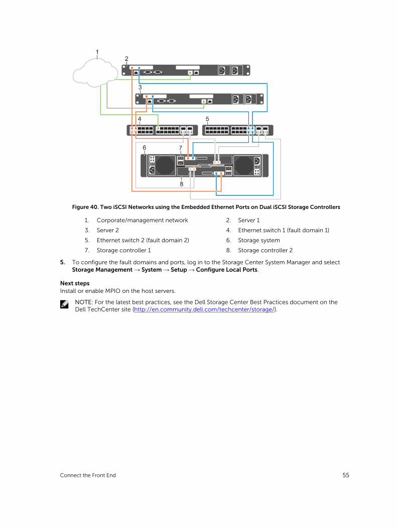
Figure 40. Two iSCSI Networks using the Embedded Ethernet Ports on Dual iSCSI Storage Controllers
1. Corporate/management network 2. Server 1
3. Server 2 4. Ethernet switch 1 (fault domain 1)
5. Ethernet switch 2 (fault domain 2) 6. Storage system
7. Storage controller 1 8. Storage controller 2
5. To configure the fault domains and ports, log in to the Storage Center System Manager and select Storage Management → System → Setup → Configure Local Ports.
Next stepsInstall or enable MPIO on the host servers.
NOTE: For the latest best practices, see the Dell Storage Center Best Practices document on the Dell TechCenter site (http://en.community.dell.com/techcenter/storage/).
Connect the Front End 55
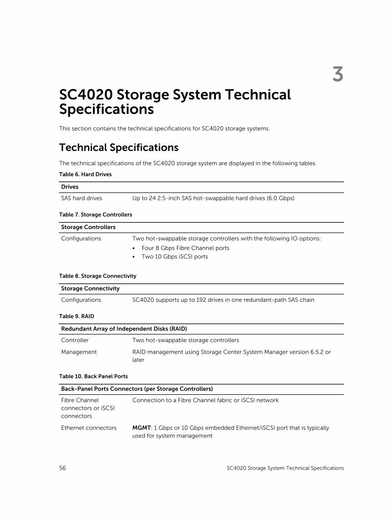
3SC4020 Storage System Technical SpecificationsThis section contains the technical specifications for SC4020 storage systems.
Technical SpecificationsThe technical specifications of the SC4020 storage system are displayed in the following tables.
Table 6. Hard Drives
Drives
SAS hard drives Up to 24 2.5-inch SAS hot-swappable hard drives (6.0 Gbps)
Table 7. Storage Controllers
Storage Controllers
Configurations Two hot-swappable storage controllers with the following IO options:
• Four 8 Gbps Fibre Channel ports
• Two 10 Gbps iSCSI ports
Table 8. Storage Connectivity
Storage Connectivity
Configurations SC4020 supports up to 192 drives in one redundant-path SAS chain
Table 9. RAID
Redundant Array of Independent Disks (RAID)
Controller Two hot-swappable storage controllers
Management RAID management using Storage Center System Manager version 6.5.2 or later
Table 10. Back Panel Ports
Back-Panel Ports Connectors (per Storage Controllers)
Fibre Channel connectors or iSCSI connectors
Connection to a Fibre Channel fabric or iSCSI network
Ethernet connectors MGMT: 1 Gbps or 10 Gbps embedded Ethernet/iSCSI port that is typically used for system management
56 SC4020 Storage System Technical Specifications
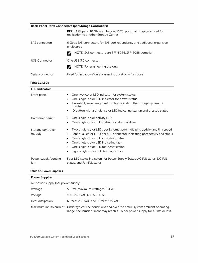
Back-Panel Ports Connectors (per Storage Controllers)
REPL: 1 Gbps or 10 Gbps embedded iSCSI port that is typically used for replication to another Storage Center
SAS connectors 6 Gbps SAS connectors for SAS port redundancy and additional expansion enclosures
NOTE: SAS connectors are SFF-8086/SFF-8088 compliant
USB Connector One USB 3.0 connector
NOTE: For engineering use only
Serial connector Used for initial configuration and support only functions
Table 11. LEDs
LED Indicators
Front panel • One two-color LED indicator for system status.
• One single-color LED indicator for power status.
• Two-digit, seven-segment display indicating the storage system ID number
• ID button with a single-color LED indicating startup and pressed states
Hard drive carrier • One single-color activity LED
• One single-color LED status indicator per drive
Storage controller module
• Two single-color LEDs per Ethernet port indicating activity and link speed
• Four dual-color LEDs per SAS connector indicating port activity and status
• One single-color LED indicating status
• One single-color LED indicating fault
• One single-color LED for identification
• Eight single-color LED for diagnostics
Power supply/cooling fan
Four LED status indicators for Power Supply Status, AC Fail status, DC Fail status, and Fan Fail status
Table 12. Power Supplies
Power Supplies
AC power supply (per power supply)
Wattage 580 W (maximum wattage: 584 W)
Voltage 100–240 VAC (7.6 A–3.0 A)
Heat dissipation 65 W at 230 VAC and 99 W at 115 VAC
Maximum inrush current Under typical line conditions and over the entire system ambient operating range, the inrush current may reach 45 A per power supply for 40 ms or less
SC4020 Storage System Technical Specifications 57
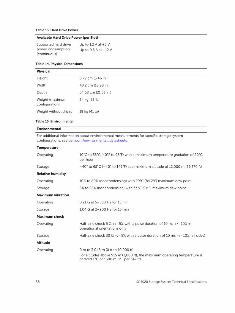
Table 13. Hard Drive Power
Available Hard Drive Power (per Slot)
Supported hard drive power consumption (continuous)
Up to 1.2 A at +5 V
Up to 0.5 A at +12 V
Table 14. Physical Dimensions
Physical
Height 8.79 cm (3.46 in.)
Width 48.2 cm (18.98 in.)
Depth 54.68 cm (21.53 in.)
Weight (maximum configuration)
24 kg (53 lb)
Weight without drives 19 kg (41 lb)
Table 15. Environmental
Environmental
For additional information about environmental measurements for specific storage system configurations, see dell.com/environmental_datasheets.
Temperature
Operating 10°C to 35°C (40°F to 95°F) with a maximum temperature gradation of 20°C per hour
Storage –40° to 65°C (–40° to 149°F) at a maximum altitude of 12,000 m (39,370 ft)
Relative humidity
Operating 10% to 80% (noncondensing) with 29°C (84.2°F) maximum dew point
Storage 5% to 95% (noncondensing) with 33°C (91°F) maximum dew point
Maximum vibration
Operating 0.21 G at 5–500 Hz for 15 min
Storage 1.04 G at 2–200 Hz for 15 min
Maximum shock
Operating Half-sine shock 5 G +/- 5% with a pulse duration of 10 ms +/- 10% in operational orientations only
Storage Half-sine shock 30 G +/- 5% with a pulse duration of 10 ms +/- 10% (all sides)
Altitude
Operating 0 m to 3,048 m (0 ft to 10,000 ft)
For altitudes above 915 m (3,000 ft), the maximum operating temperature is derated 1°C per 300 m (1°F per 547 ft)
58 SC4020 Storage System Technical Specifications

Environmental
Storage –300 m to 12,192 m (–1000 ft to 40,000 ft)
Airborne Contaminant Level
Class G1 or lower as defined by ISA-S71.04-1985
SC4020 Storage System Technical Specifications 59