Embed Size (px)
Citation preview
tech
nic
al
cata
log
ue
Del
Ph
i ser
ies J
UL
16
REV.
13
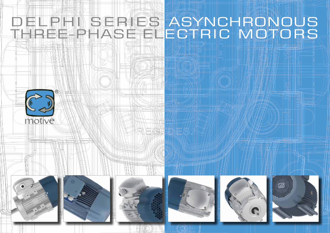
dELphi sERiEs asynchRonoUs thREE-phasE ELEctRic motoRs

CERTIFICATONr 50 100 1185 - Rev. 08Si attesta che / This is to certify that
IL SISTEMA QUALITÀ DITHE QUALITY SYSTEM OF
MOTIVE S.r.l.SEDE LEGALE E OPERATIVA:REGISTERED OFFICE AND OPERATIONAL SITE:
VIA LE GHISELLE 20I-25014 CASTENEDOLO (BS)È CONFORME AI REQUISITI DELLA NORMA
HAS BEEN FOUND TO COMPLY WITH THE REQUIREMENTS OFUNI EN ISO 9001:2008QUESTO CERTIFICATO È VALIDO PER IL SEGUENTE CAMPO DI APPLICAZIONETHIS CERTIFICATE IS VALID FOR THE FOLLOWING SCOPE
Progettazione e fabbricazione di motori elettrici, riduttori meccanici e inverter per la trasmissione di potenza (IAF 18, 19)
Design and manufacture of electrical motors, mechanical reducers and inverter for power transmissions (IAF 18, 19)
Per l’Organismo di CertificazioneFor the Certification BodyTÜV Italia S.r.l.Validità /Validity
Dal / From: 2016-04-26Al / To: 2018-09-14
Data emissione / Printing DateAndrea CosciaDirettore Divisione Management Service 2016-04-26PRIMA CERTIFICAZIONE / FIRST CERTIFICATION: 2001-07-20“LA VALIDITÀ DEL PRESENTE CERTIFICATO È SUBORDINATA A SORVEGLIANZA PERIODICA A 12 MESI E AL RIESAME COMPLETO DEL SISTEMA DI
GESTIONE AZIENDALE CON PERIODICITÀ TRIENNALE”
“THE VALIDITY OF THE PRESENT CERTIFICATE DEPENDS ON THE ANNUAL SURVEILLANCE EVERY 12 MONTHS AND ON THE COMPLETE REVIEW OF
COMPANY'S MANAGEMENT SYSTEM AFTER THREE-YEARS”
DataAndrea CosciaDirettore Divisione Management Service
VISIT AND KNOW MOTIVE THANKS TO THE MOVIE ON WWW.MOTIVE.IT
230 ± 10% 230 ± 5% 1 1 0,83 1,2 0,83 0,83 0,83230 ± 10% 230 ± 10% 1 0,95 0,83 1,2 0,83 0,83 0,83230 ± 10% 240 ± 5% 1,05 1 0,87 1,2 0,87 0,87 0,87400 ± 10% 380 ± 5% 1 1 0,83 1,2 0,83 0,83 0,83400 ± 10% 400 ± 10% 1 0,95 0,83 1,2 0,83 0,83 0,83400 ± 10% 415 ± 10% 1,05 1 0,87 1,2 0,87 0,87 0,87400 ± 10% 440 ± 10% 1,10 1 0,90 1,2 0,93 0,93 0,93400 ± 10% 460 ± 5% 1,15 1 0,96 1,2 0,96 0,96 0,96400 ± 10% 480 ± 5% 1,20 1 1 1,2 1 1 1
Volt 230 380 400 440 690
In 1,74 1,05 1,00 0,91 0,64
In Corrente nominale:In è la corrente espressa in Ampereassorbita dal motore quando è alimentatoalla tensione nominale Vn [V] ed erogala potenza nominale Pn [W]. Si ottienedalla formula:
Nelle seguenti tabelle prestazionali,le correnti nominali sono riferite allatensione di 400 V. Per altre tensionile correnti si possono ritenereinversamente proporzionali al rapportodelle tensioni.es:
I motori sono in grado di sopportareanche temporanei sovraccarichi, conincremento di corrente pari a 1,5volte quella nominale per un tempo dialmeno 2 minuti.
Corrente di spunto Is o avviamento(o a rotore bloccato):Vedi grafico
Cn(Nm)
rpmIs(A)
Cs(Nm)
per maggiori informazioni consultare il capitolo “schemi di collegamento” a pag. 12Il "datasheet creator" nell'area di download del sito www.miotive.it, permette di vedere i dati prestazionaliriparametrati in base a Volt ed Hz impostati dall'utente.
Potenza nominale:è la potenza meccanica misurataall’albero, espressa secondo le ultimeindicazioni date dai comitati internazionaliin Watt o multipl i (W o KW).Molto usata, tuttavia, nel settoretecn ico, è ancora la potenzaespressa in cavalli (HP)
Tensione nominale:la tensione espressa in Volt daapplicare ai morsetti del motoreconformemente a quanto specificatonelle successive tabelle
Frequenza:In questo catalogo tutti i dati tecnicisono riferiti a motori trifase avvolti a50Hz. Gli stessi possono esserealimentati a 60 Hz tenendo conto deicoefficenti moltiplicativi della tabella:
Velocità sincrona:si esprime in rpm ed è data dallaformula
f 120/p dovef= frequenza di alimentazione Hzp= numero di paia di poli
Coppia nominale:Cn è la coppia espressa in Nmcorrispondente alla potenza nominale eai giri nominali. E’ data dal prodotto di unaforza per il braccio (distanza) e si misurain Nm poiché la forza è espressa in Newtone la distanza in metri. Il valore della coppianominale si ottiene dalla formula
Cn (Nm) = Pn x 9550 / rpmPn= potenza nominale in KWrpm = velocità di rotazione nominale
Coppia di spunto o di avviamento(o a rotore bloccato):Cs è la coppia fornita dalmotore e rotore fermo conalimentazione a tensione efrequenze nominali.
Coppia massima:Cmax è la coppia massima cheil motore può svilupparedurante il suo funzionamentocon alimentazione a tensione efrequenza nominali, in funzionedelle velocità.Rappresenta anche il valoredella coppia resistente oltre la quale ilmotore si blocca.
Fattore di potenza o cos :rappresenta il coseno dell’angolo disfasamento tra la tensione e lacorrente.
TargaVolt a 50Hz
IpotesiVolt a 60Hz
potenza kW
In(A)
Le caratteristiche tecniche elettriche sono elencate nelle tabelle tecniche prestazionali riportate di seguito. Per comprenderne i contenuti, si premettono alcune definizionidi carattere generale:
DATI TECNICI
Rendimento: si esprime in % ed è dato dal
rapporto tra la potenza utile e lasomma della potenza utile e le perditesul motore, ovvero la potenza realeassorbita dal motore.Le perdite sui motori elettrici sonoprincipalmente di due tipi: per effettojoule (rotore e statore) e le perditedovute alle caratteristiche fisiche dellelamiere. Queste ultime produconoessenzialmente calore.Un rendimento più alto significamotori più efficienti e risparmi dienergia. Più un motore è piccolo,più la presenza di paraolio a doppiolabbro di tenuta come quelli usatisul lato trasmissione dei motoridelphi flangiati (B5 o B14) puòinfluire, a seguito dell'attritogenerato, sul rendimento.I motori B3 fino alla taglia 132,invece, montano dei v-ring conattrito pressoché nullo. Persemplicità, le seguenti tabelleprestazionali riportano gli
assorbimenti ed i rendimenti misuratisu motori B14 per la taglia 56, emotori B3 dalla taglia 63 in su.
Cmax(Nm)
24
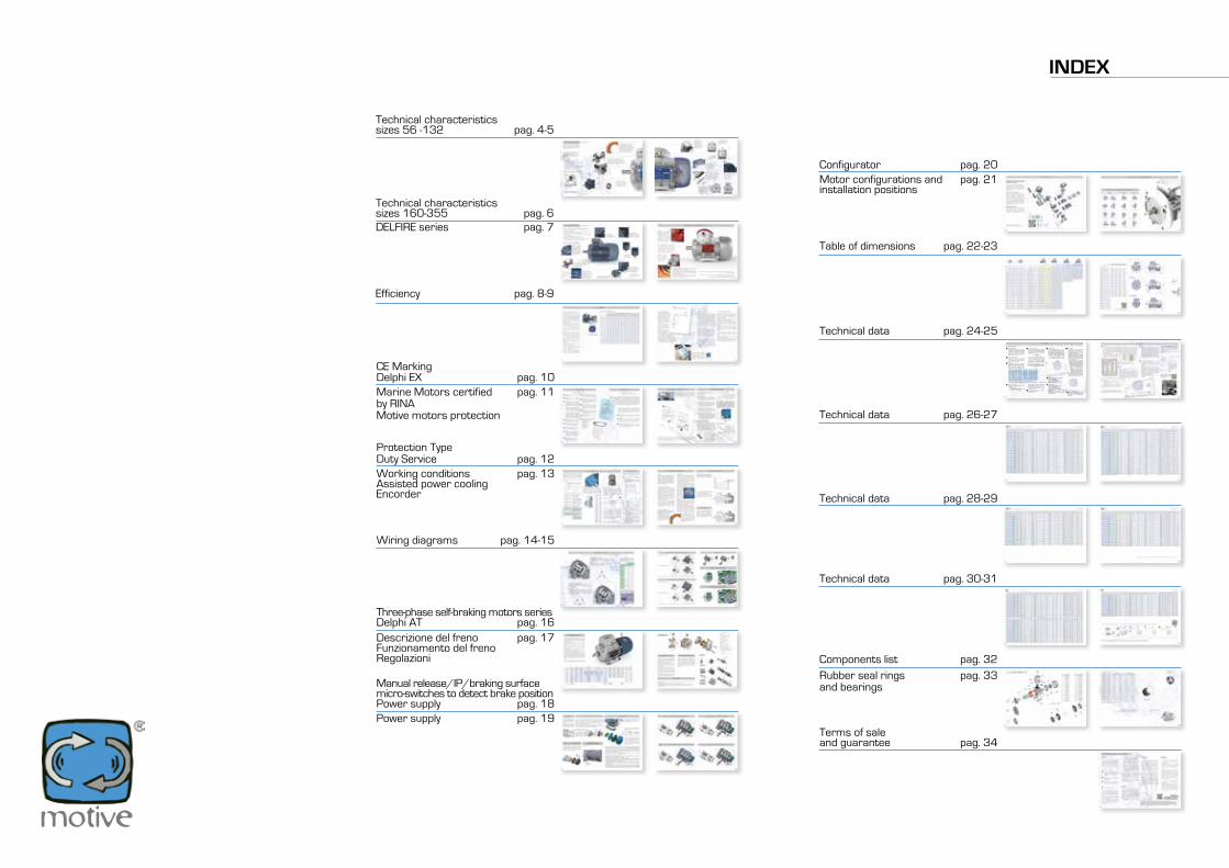
INDEX
Technical characteristics sizes 56 -132 pag. 4-5
Efficiency pag. 8-9
Wiring diagrams pag. 14-15
Three-phase self-braking motors seriesDelphi AT pag. 16Descrizione del freno pag. 17Funzionamento del frenoRegolazioni
Manual release/IP/braking surfacemicro-switches to detect brake positionPower supply pag. 18Power supply pag. 19
Configurator pag. 20Motor configurations and pag. 21installation positions
Table of dimensions pag. 22-23
Technical data pag. 24-25
Technical data pag. 26-27
Technical data pag. 28-29
Technical data pag. 30-31
Terms of saleand guarantee pag. 34
Components list pag. 32Rubber seal rings pag. 33and bearings
CE MarkingDelphi EX pag. 10Marine Motors certified pag. 11by RINA Motive motors protection
Protection TypeDuty Service pag. 12Working conditions pag. 13Assisted power coolingEncorder
Technical characteristics sizes 160-355 pag. 6DElFIRE series pag. 7
IE2, high efficiency class IEC 60034-30-1IE3, premium efficiency class IEC 60034-30-1
MONOI motori motive sono realizzati secondo le norme internazionali di unificazione; ogni dimensione, per tutte le forme costruttive, è stata dedotta facendo riferimento alle tabelle relative alla norma IEC 72-1.La carcassa è ottenuta da pressofusione in lega d’alluminio.
Tutti i motori MONO sono:monofase 230V 50Hz. Su richiesta voltaggi speciali e frequenza 60Hzclasse di isolamento F, (H su richiesta)servizio continuo S1,protezione IP55, (IP56, 66 e 67 su richiesta)
condensatore per alta coppia di spunto opzionale
Lo speciale avvolgimento permette una coppia di spunto sufficiente anche senza un doppio condensatore di marcia e avviamento
Solo cuscinetti selezionati per la loro silenziosità e affidabilità nel tempo, e, per gli stessi obiettivi, il rotore viene equilibrato dinamicamente
Per assicurare la loro ermeticità sono dotati di importanti dettagli come i pressacavi antistrappo e l’abbinamento di cuscinetti schermati e paraolio su entrambi i lati del motore
la cassetta connessioni è predisposta per invertire con facilità la posizione del pressacavo
la cassetta connessioni può girare su sè stessa
I piedini sono staccabili e montabili su 3 lati predisposti, in modo da poter posizionare il coprimorsettiera sul lato desiderato del motore.
1
TECHNICAl CHARACTERISTICS
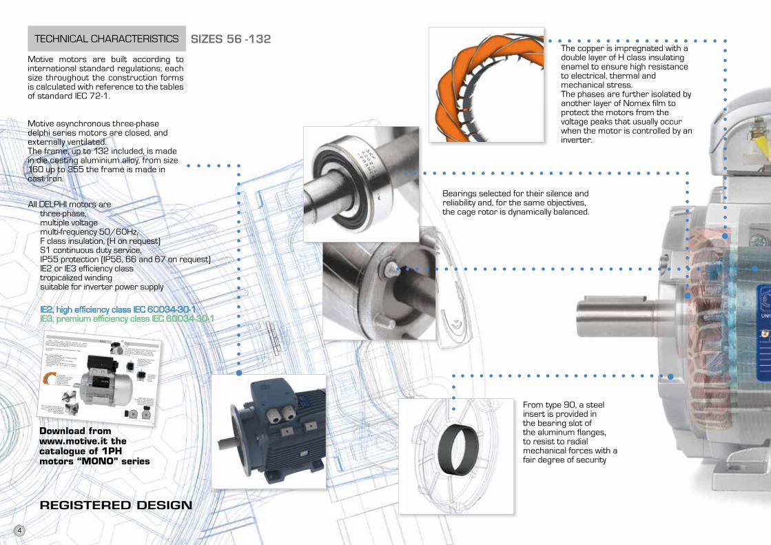
Motive motors are built according to international standard regulations; each size throughout the construction forms is calculated with reference to the tables of standard IEC 72-1.
Motive asynchronous three-phase delphi series motors are closed, and externally ventilated.The frame, up to 132 included, is made in die casting aluminium alloy, from size 160 up to 355 the frame is made in cast iron.
The copper is impregnated with a double layer of H class insulating enamel to ensure high resistance to electrical, thermal and mechanical stress.The phases are further isolated byanother layer of Nomex film to protect the motors from the voltage peaks that usually occur when the motor is controlled by an inverter.
From type 90, a steel insert is provided in the bearing slot of the aluminum flanges, to resist to radial mechanical forces with a fair degree of security
registered design
Download from www.motive.it the catalogue of 1PH motors “MONO” series
siZes 56 -132
All DElPHI motors arethree-phase,multiple voltagemulti-frequency 50/60Hz,F class insulation, (H on request)S1 continuous duty service,IP55 protection (IP56, 66 and 67 on request)IE2 or IE3 efficiency classtropicalized windingsuitable for inverter power supply
Bearings selected for their silence and reliability and, for the same objectives, the cage rotor is dynamically balanced.
4
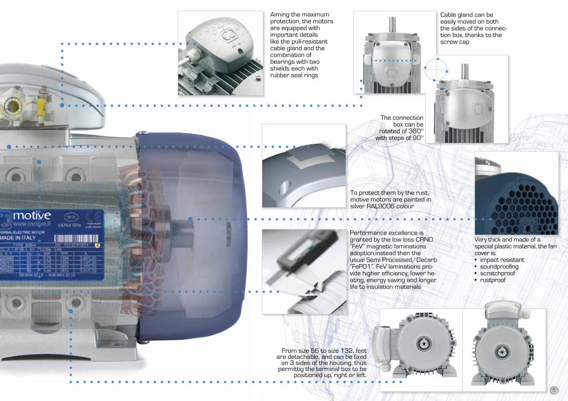
Aiming the maximumprotection, the motors are equipped with important details like the pull-resistant cable gland and the combination ofbearings with two shields each with rubber seal rings
Cable gland can be easily moved on both the sides of the connec-tion box, thanks to the screw cap
The connection box can be
rotated of 360° with steps of 90°
To protect them by the rust, motive motors are painted in silver RAl9006 colour
From size 56 to size 132, feet are detachable, and can be fixed
on 3 sides of the housing, thus permittig the terminal box to be
positioned up, right or left.
Performance excellence is granted by the low loss CRNO “FeV” magnetic laminations adoption,instead then the usual Semi Processed/Decarb “FeP01”. FeV laminations pro-vide higher efficiency, lower he-ating, energy saving and longer life to insulation materials
Very thick and made of a special plastic material, the fan cover is:• impact resistant• soundproofing• scratchproof• rustproof
5
IE2, high efficiency class IEC 60034-30-1IE3, premium efficiency class IEC 60034-30-1
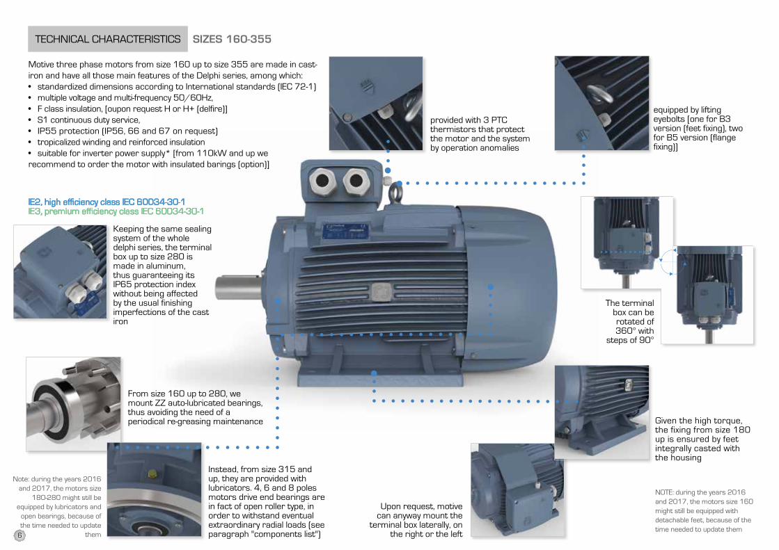
Motive three phase motors from size 160 up to size 355 are made in cast-iron and have all those main features of the Delphi series, among which:• standardized dimensions according to International standards (IEC 72-1)• multiple voltage and multi-frequency 50/60Hz,• F class insulation, [oupon request H or H+ (delfire)]• S1 continuous duty service,• IP55 protection (IP56, 66 and 67 on request)• tropicalized winding and reinforced insulation• suitable for inverter power supply* [from 110kW and up we recommend to order the motor with insulated barings (option)]
provided with 3 PTC thermistors that protect the motor and the system by operation anomalies
Keeping the same sealing system of the whole delphi series, the terminal box up to size 280 is made in aluminum, thus guaranteeing its IP65 protection index without being affected by the usual finishing imperfections of the cast iron
From size 160 up to 280, we mount ZZ auto-lubricated bearings, thus avoiding the need of a periodical re-greasing maintenance
Instead, from size 315 and up, they are provided with lubricators. 4, 6 and 8 poles motors drive end bearings are in fact of open roller type, in order to withstand eventual extraordinary radial loads (see paragraph "components list")
Note: during the years 2016 and 2017, the motors size
180-280 might still be equipped by lubricators and
open bearings, because of the time needed to update
them
equipped by lifting eyebolts [one for B3 version (feet fixing), two for B5 version (flange fixing)]
Given the high torque, the fixing from size 180 up is ensured by feet integrally casted with the housing
The terminal box can berotated of 360° with
steps of 90°
Upon request, motive can anyway mount the
terminal box laterally, on the right or the left
TECHNICAl CHARACTERISTICS siZes 160-355
NOTE: during the years 2016 and 2017, the motors size 160 might still be equipped with detachable feet, because of the time needed to update them
6
DElFIRE SERIES, 100°C RESISTANT MOTORS
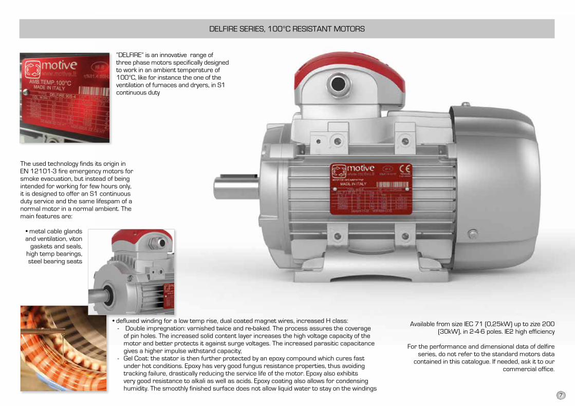
“DElFIRE” is an innovative range of three phase motors specifically designed to work in an ambient temperature of 100°C, like for instance the one of the ventilation of furnaces and dryers, in S1 continuous duty
• defluxed winding for a low temp rise, dual coated magnet wires, increased H class:- Double impregnation: varnished twice and re-baked. The process assures the coverage
of pin holes. The increased solid content layer increases the high voltage capacity of the motor and better protects it against surge voltages. The increased parasitic capacitance gives a higher impulse withstand capacity;
- Gel Coat: the stator is then further protected by an epoxy compound which cures fast under hot conditions. Epoxy has very good fungus resistance properties, thus avoiding tracking failure, drastically reducing the service life of the motor. Epoxy also exhibits very good resistance to alkali as well as acids. Epoxy coating also allows for condensing humidity. The smoothly finished surface does not allow liquid water to stay on the windings
Available from size IEC 71 (0,25kW) up to zize 200 (30kW), in 2-4-6 poles. IE2 high efficiency
For the performance and dimensional data of delfire series, do not refer to the standard motors data
contained in this catalogue. If needed, ask it to our commercial office.
The used technology finds its origin in EN 12101-3 fire emergency motors for smoke evacuation, but instead of being intended for working for few hours only, it is designed to offer an S1 continuous duty service and the same lifespam of a normal motor in a normal ambient. The main features are:
• metal cable glands and ventilation, viton
gaskets and seals, high temp bearings, steel bearing seats
7
KW Hp
0,12 0,18 45,0 50,0 38,3 31,0 53,6 59,1 50,6 39,8 60,8 64,8 57,7 50,70,18 0,25 52,8 57,0 45,5 38,0 60,4 64,7 56,6 45,9 65,9 69,9 63,9 58,70,25 0,35 58,2 61,5 52,1 43,4 64,8 68,5 61,6 50,6 69,7 73,5 68,6 64,10,37 0,5 63,9 66,0 59,7 49,7 69,5 72,7 67,6 56,1 73,8 77,3 73,5 69,30,55 0,75 69,0 70,0 65,8 56,1 74,1 77,1 73,1 61,7 77,8 80,8 77,2 73,00,75 1 72,1 72,1 70,0 61,2 77,4 79,6 75,9 66,2 80,7 82,5 78,9 75,01,1 1,5 75,0 75,0 72,9 66,5 79,6 81,4 78,1 70,8 82,7 84,1 81,0 77,71,5 2 77,2 77,2 75,2 70,2 81,3 82,8 79,8 74,1 84,2 85,3 82,5 79,72,2 3 79,7 79,7 77,7 74,2 83,2 84,3 81,8 77,6 85,9 86,7 84,3 81,93 4 81,5 81,5 79,7 77,0 84,6 85,5 83,3 80,0 87,1 87,7 85,6 83,54 5,5 83,1 83,1 81,4 79,2 85,8 86,6 84,6 81,9 88,1 88,6 86,8 84,8
5,5 7,5 84,7 84,7 83,1 81,4 87,0 87,7 86,0 83,8 89,2 89,6 88,0 86,27,5 10 86,0 86,0 84,7 83,1 88,1 88,7 87,2 85,3 90,1 90,4 89,1 87,311 15 87,6 87,6 86,5 85,0 89,4 89,8 88,7 86,9 91,2 91,4 90,3 88,615 20 88,7 88,7 87,7 86,2 90,3 90,6 89,7 88,0 91,9 92,3 91,2 89,6
18,5 25 89,3 89,3 88,6 86,9 90,9 91,2 90,4 88,6 92,4 92,6 91,7 90,122 30 89,9 89,9 89,2 87,4 91,3 91,6 90,9 89,1 92,7 93,0 92,2 90,630 40 90,7 90,7 90,2 88,3 92,0 92,3 91,7 89,8 93,3 93,6 92,9 91,337 50 91,2 91,2 90,8 88,8 92,5 92,7 92,2 90,3 93,7 93,9 93,3 91,845 60 91,7 91,7 91,4 89,2 92,9 93,1 92,7 90,7 94,0 94,2 93,7 92,255 75 92,1 92,1 91,9 89,7 93,2 93,5 93,1 91,0 94,3 94,6 94,1 92,575 100 92,7 92,7 92,6 90,3 93,8 94,0 93,7 91,6 94,7 95,0 94,6 93,190 120 93,0 93,0 92,9 90,7 94,1 94,2 94,0 91,9 95,0 95,2 94,9 93,4
110 150 93,3 93,3 93,3 91,1 94,3 94,5 94,3 92,3 95,2 95,4 95,1 93,7132 180 93,5 93,5 93,5 91,5 94,6 94,7 94,6 92,6 95,4 95,6 95,4 94,0160 220 93,8 93,8 93,8 91,9 94,8 94,9 94,8 93,0 95,6 95,8 95,6 94,3200 270 94,0 94,0 94,0 92,5 95,0 95,1 95,0 93,5 95,8 96,0 95,8 94,6250 335 94,0 94,0 94,0 92,5 95,0 95,1 95,0 93,5 95,8 96,0 95,8 94,6315 423 94,0 94,0 94,0 92,5 95,0 95,1 95,0 93,5 95,8 96,0 95,8 94,6355 483 94,0 94,0 94,0 92,5 95,0 95,1 95,0 93,5 95,8 96,0 95,8 94,6
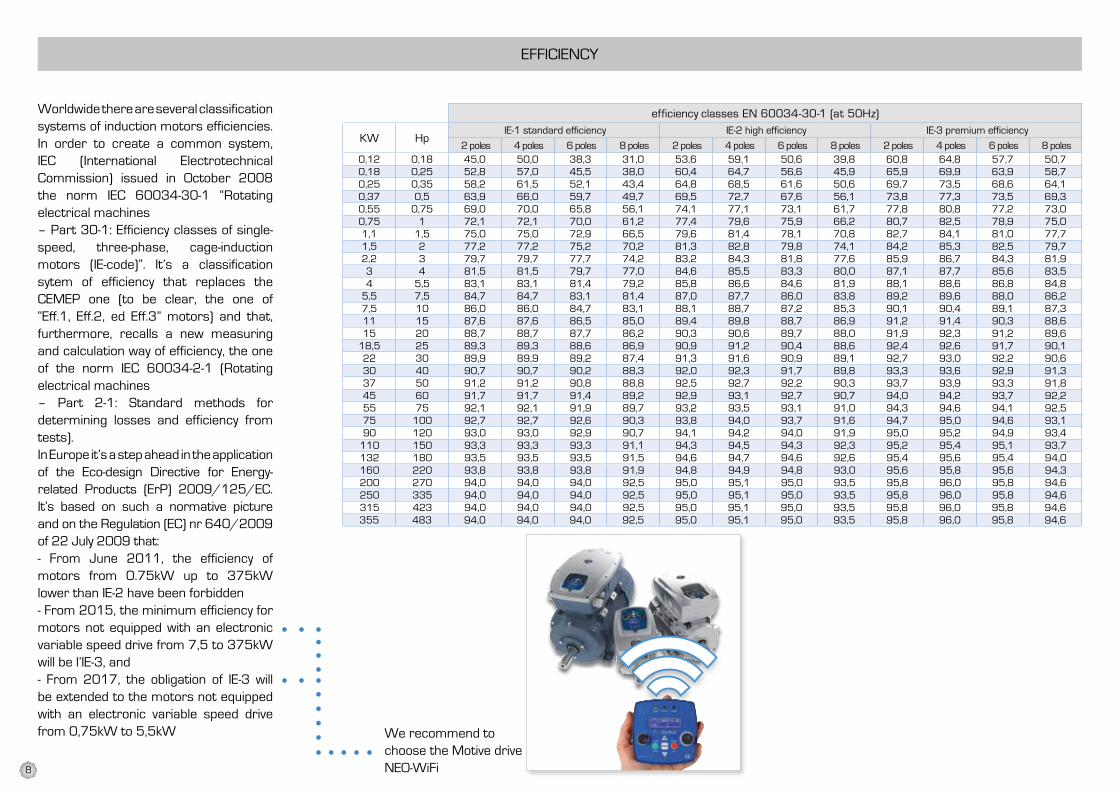
Worldwide there are several classification systems of induction motors efficiencies. In order to create a common system, IEC (International Electrotechnical Commission) issued in October 2008 the norm IEC 60034-30-1 “Rotating electrical machines– Part 30-1: Efficiency classes of single- speed, three-phase, cage-induction motors (IE-code)”. It’s a classification sytem of efficiency that replaces the CEMEP one (to be clear, the one of “Eff.1, Eff.2, ed Eff.3” motors) and that, furthermore, recalls a new measuring and calculation way of efficiency, the one of the norm IEC 60034-2-1 (Rotating electrical machines– Part 2-1: Standard methods for determining losses and efficiency from tests).In Europe it’s a step ahead in the application of the Eco-design Directive for Energy- related Products (ErP) 2009/125/EC. It’s based on such a normative picture and on the Regulation (EC) nr 640/2009 of 22 July 2009 that:- From June 2011, the efficiency of motors from 0.75kW up to 375kW lower than IE-2 have been forbidden- From 2015, the minimum efficiency for motors not equipped with an electronic variable speed drive from 7,5 to 375kW will be l’IE-3, and- From 2017, the obligation of IE-3 will be extended to the motors not equipped with an electronic variable speed drive from 0,75kW to 5,5kW
efficiency classes EN 60034-30-1 (at 50Hz)
EFFICIENCY
IE-1 standard efficiency IE-2 high efficiency IE-3 premium efficiency
2 poles 4 poles 6 poles 8 poles 2 poles 4 poles 6 poles 8 poles 2 poles 4 poles 6 poles 8 poles
We recommend to choose the Motive drive NEO-WiFi 8
Clients benefits are of many kinds:
BIll EFFECTSThe purchase cost of a motor is about 2-3% of the total costs of its life. The balanceis energy consumption costs. ComparingIE3 motors to IE2, the purchase pricedifference is recovered in about one yearof energy saving. Of course, such periodlength depends by the specific motor, theuse of it and the local energy costs of eachCountry.
DURABIlITY EFFECTSHigher efficiency motors heat less, slowingdown the aging cycle of the insulatingmaterials and living longer. The average life is approximately from 35 to 40,000 hours for IE2 motors up to 15kW and 60,000 for IE2 bigger motors. IE3 motors can live approx 40% longer than IE2 motors.
AMBIENT EFFECTSElectric motors use 65% of all electricityin industry. Higher efficiency motors havethe further objective of sustainabledevelopment, reduction of CO2 emissionsand consequent improvement o fthe quality of the atmosphere with anobjective of sustainable development,Reduction of CO2 emissions and consequentimprovement of the quality of theatmosphere.
How to make a more efficient motor?
High efficiency can be seen in many ways: like the relation between output power and input absorbed power, or like a measure of the losses that born when converting the electric power in mechanical energy.From another perspective, high efficiency motors consume less energy to produce the same torque on the shaft. Basically, an high efficiency motor is the result of precise machining, lower frictions, a dynamically balanced rotor, smaller space between rotor and stator and of the use of better materials. The main factors for the design are based on the choice of the type of lamination sheets and windings. Motive motors are made with “FeV” magnetic lamination sheets, rather than the customary iron lamination sheets.Composition and thickness give to magnetic lamination sheets a very low W/Kg loosing factor.lower specific losses mean less magnetisingcurrent for the same Power and torque (thus less heating).
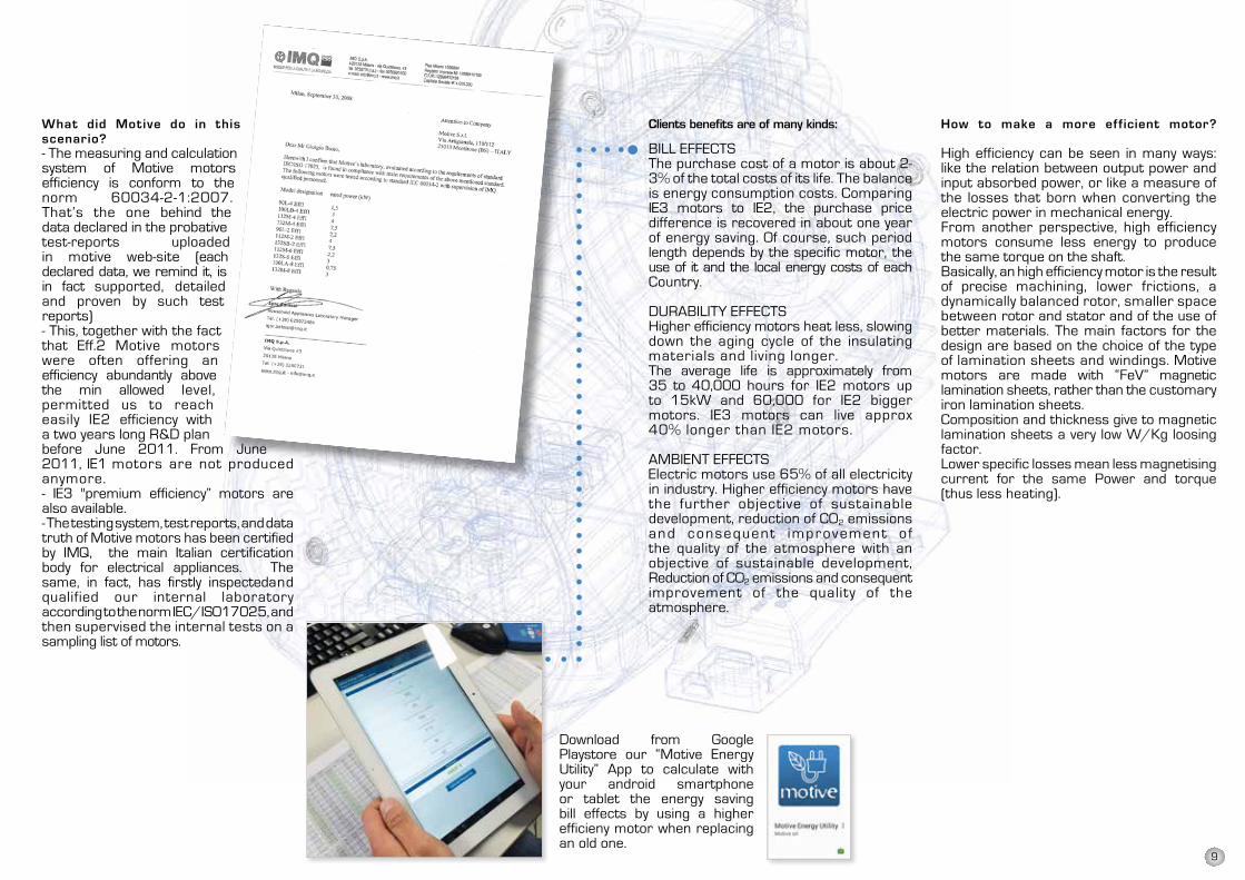
What did Motive do in this scenario?- The measuring and calculation system of Motive motors efficiency is conform to the norm 60034-2-1:2007. That’s the one behind the data declared in the probativetest-reports uploaded in motive web-site (each declared data, we remind it, is in fact supported, detailed and proven by such test reports)- This, together with the fact that Eff.2 Motive motors were often offering an efficiency abundantly above the min allowed level, permitted us to reach easily IE2 efficiency with a two years long R&D planbefore June 2011. From June 2011, IE1 motors are not produced anymore.- IE3 "premium efficiency” motors are also available.- The testing system, test reports, and data truth of Motive motors has been certified by IMQ, the main Italian certification body for electrical appliances. The same, in fact, has firstly inspectedand qualified our internal laboratoryaccording to the norm IEC/ISO17025, andthen supervised the internal tests on asampling list of motors.
Download from Google Playstore our “Motive Energy Utility” App to calculate with your android smartphone or tablet the energy saving bill effects by using a higher efficieny motor when replacing an old one.
9
II 3G Ex nA IIB T4 GcII 3D Ex tc IIIB T125°C Dc
Low Voltage 06/95 EEC
EMC Electromagnetic Compatibility04/108/EEC
Eco-design Directive for Energy-relatedProducts (ErP) 2009/125/EC
Note: The Machinery Directive (MD)2006/42/EC excludes from itsscope the electric motors (Art.1,comma 2)
CE marking is put by Motive as avisible sign of the product compliancewith the requirements of abovementioned directives. In order to reachthis conformity, Motive productsrespect the following productstandards:
EN 60034-1 (last issue). Rotatingelectrical machines. Part 1: ratingand performance
EN 60034-5 (last issue). Rotatingelectrical machines. Part 5:classification of degrees of protection
EN 60034-6 (last issue). Rotatingelectrical machines. Part 6: methodsof cooling (IC code)
EN60034-7 Rotating ElectricalMachines - Part 7: Classificationof Types of Construction,Mounting Arrangements andTerminal Box Position (IM Code)
EN60034-8 Rotating electricalmachines–Part 8: Terminalmarkings and direction of rotation
marking is referred to:
CE MARKING SERIE DELPHI EX
EN60034-2-1 (last issue). Rotatingelectrical machines. Standardmethods for determining lossesand efficiency from tests
EN60034-30 (last issue). Rotatingelectrical machines - Part 30:Efficiency classes of single-speed,three-phase, cage-induction motors
EN50347 General purpose three-phase induction motors havingstandard dimensions and outputs.Frame numbers 56 to 315 andflange numbers 65 to 740
EN60335-1 Household and similarelectrical appliances – Safety
EN61000-6-4 Electromagneticcompatibility (EMC) - Part 6: Genericstandards - Section 4: Emissionstandard for industrial environments
EN 60034-9 (last issue). Rotatingelectrical machines. Part 9: noise limits
IEC 72-1 Dimensions and output series for rotating electrical machines Part 1: Frame numbers 56 to 400 and flange numbers 55 to 1080
EN60079-0 Electrical apparatus for explosive gasatmospheres - Part 0: General requirements
EN60079-15 Electrical apparatus for explosive gasatmospheres - Part 15: Construction, test andmarking of type of protection, "n" electrical apparatus
EN60079-31 Explosive atmospheresPart 31: Equipment dust ignition protection byenclosure “t”
EN50281-2-1 Electrical apparatus for use in thepresence of combustible dust. Test methods. Methodsof determining minimum ignition temperatures
Motive delphi Ex motors are designed to be used inthe zone 22 (II 3 D T125°') and/or zone 2 (II 3 GT125°'), according to the classification stated in theplate, and for the voltage and frequency field A describedby the norm EN 60034 part 1 Cap. 6.3.
II 3 GDEx nA T4Ex tD A22 IP65 125°C
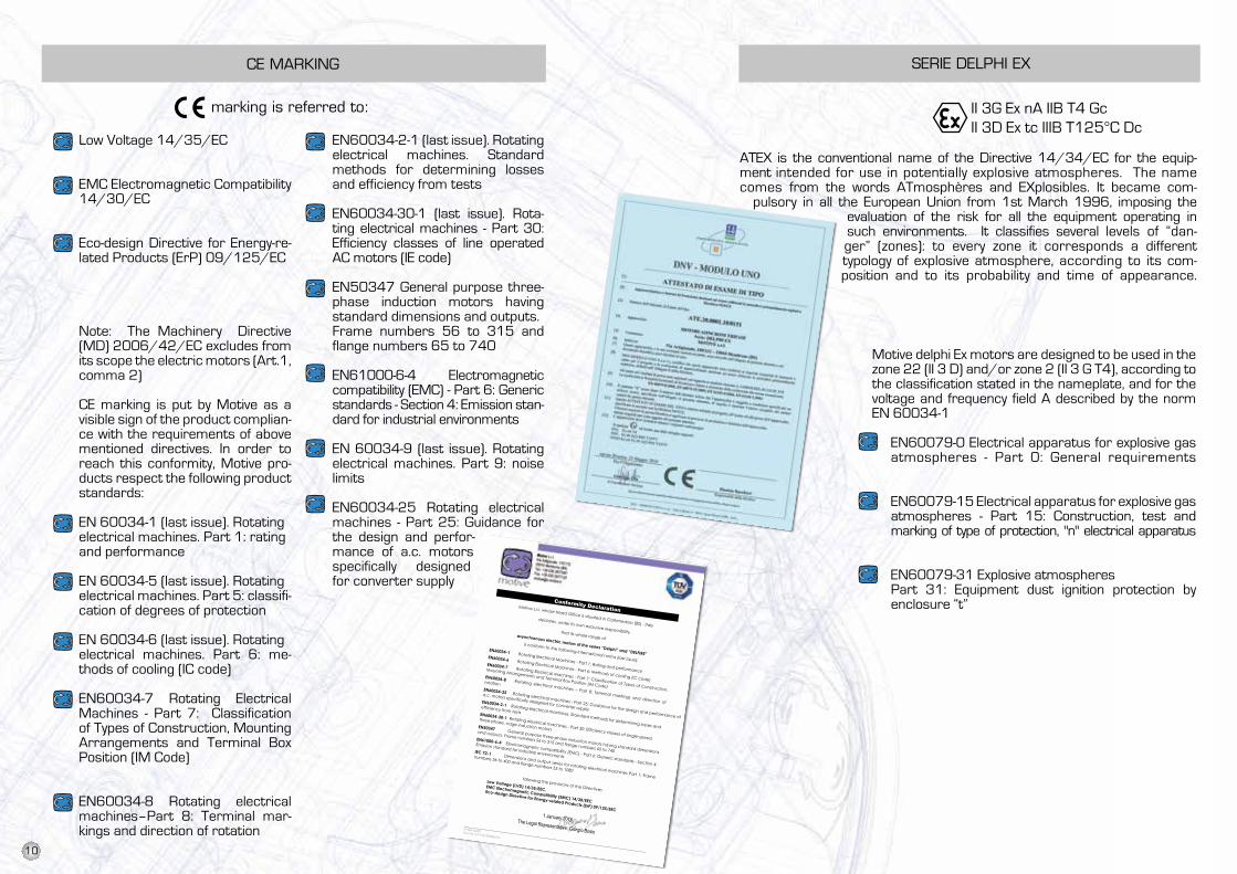
ATEX is the conventional name of the Directive 94/9/EC for the equipmentintended for use in potentially explosive atmospheres. The name comesfrom the words ATmosphères and EXplosibles. It became compulsory in allthe European Union from 1st March 1996, imposing the evaluation of therisk for all the equipment operating in such environments. It classifies several
levels of "danger" (zones): to every zone it corresponds a different typology of explosive atmosphere, according to its composition and to its probability and time of appearance.
The client is responsible of the choice of the right motor based on the criteria described in the norm EN 61241-14. EN 61241-14.
low Voltage 14/35/EC
EMC Electromagnetic Compatibility14/30/EC
Eco-design Directive for Energy-re-lated Products (ErP) 09/125/EC
Note: The Machinery Directive (MD) 2006/42/EC excludes from its scope the electric motors (Art.1,comma 2)
CE marking is put by Motive as a visible sign of the product complian-ce with the requirements of above mentioned directives. In order to reach this conformity, Motive pro-ducts respect the following productstandards:
EN 60034-1 (last issue). Rotatingelectrical machines. Part 1: ratingand performance
EN 60034-5 (last issue). Rotatingelectrical machines. Part 5: classifi-cation of degrees of protection
EN 60034-6 (last issue). Rotatingelectrical machines. Part 6: me-thods of cooling (IC code)
EN60034-7 Rotating Electrical Machines - Part 7: Classification of Types of Construction, Mounting Arrangements and Terminal Box Position (IM Code)
EN60034-8 Rotating electrical machines–Part 8: Terminal mar-kings and direction of rotation
EN60034-2-1 (last issue). Rotating electrical machines. Standard methods for determining losses and efficiency from tests
EN60034-30-1 (last issue). Rota-ting electrical machines - Part 30: Efficiency classes of line operated AC motors (IE code)
EN50347 General purpose three- phase induction motors having standard dimensions and outputs.Frame numbers 56 to 315 and flange numbers 65 to 740
EN61000-6-4 Electromagnetic compatibility (EMC) - Part 6: Generic standards - Section 4: Emission stan-dard for industrial environments
EN 60034-9 (last issue). Rotating electrical machines. Part 9: noise limits
EN60034-25 Rotating electrical machines - Part 25: Guidance for the design and perfor-mance of a.c. motors specifically designed for converter supply
ATEX is the conventional name of the Directive 14/34/EC for the equip-ment intended for use in potentially explosive atmospheres. The name comes from the words ATmosphères and EXplosibles. It became com-
pulsory in all the European Union from 1st March 1996, imposing the evaluation of the risk for all the equipment operating in such environments. It classifies several levels of “dan-ger” (zones): to every zone it corresponds a different typology of explosive atmosphere, according to its com-position and to its probability and time of appearance.
N. REA 422301 Cod. Fisc. e P. IVA 03580280174
Motive s.r.l. Via Le Ghiselle, 20 25014 Castenedolo (BS) Tel.: +39 030 2677087 Fax: +39 030 2677125 [email protected]
Conformity Declaration Motive s.r.l. whose Head Office is situated in Castenedolo (BS) - Italy
declares, under its own exclusive responsibility, that its whole range of asynchronous electric motors of the series “Delphi” and “DELFIRE”
is conform to the following international norms (last issue):
EN60034-1 Rotating Electrical Machines - Part 1: Rating and performance
EN60034-6 Rotating Electrical Machines - Part 6: Methods of cooling (IC code)
EN60034-7 Rotating Electrical Machines - Part 7: Classification of Types of Construction,
Mounting Arrangements and Terminal Box Position (IM Code)
EN60034-8 Rotating electrical machines – Part 8: Terminal markings and direction of
rotation EN60034-25 Rotating electrical machines - Part 25: Guidance for the design and performance of
a.c. motors specifically designed for converter supply
EN60034-2-1 Rotating electrical machines. Standard methods for determining losses and
efficiency from tests EN60034-30-1 Rotating electrical machines - Part 30: Efficiency classes of single-speed,
three-phase, cage-induction motors EN50347 General purpose three-phase induction motors having standard dimensions
and outputs. Frame numbers 56 to 315 and flange numbers 65 to 740
EN61000-6-4 Electromagnetic compatibility (EMC) - Part 6: Generic standards - Section 4:
Emission standard for industrial environments IEC 72-1 Dimensions and output series for rotating electrical machines Part 1: Frame
numbers 56 to 400 and flange numbers 55 to 1080
following the provisions of the Directives
Low Voltage (LVD) 14/35/EEC, EMC Electromagnetic Compatibility (EMC) 14/30/EEC
Eco-design Directive for Energy-related Products (ErP) 09/125/EEC 1 January 2016 The Legal Representative: Giorgio Bosio
Motive delphi Ex motors are designed to be used in the zone 22 (II 3 D) and/or zone 2 (II 3 G T4), according to the classification stated in the nameplate, and for the voltage and frequency field A described by the norm EN 60034-1
EN60079-0 Electrical apparatus for explosive gasatmospheres - Part 0: General requirements
EN60079-15 Electrical apparatus for explosive gasatmospheres - Part 15: Construction, test andmarking of type of protection, "n" electrical apparatus
EN60079-31 Explosive atmospheresPart 31: Equipment dust ignition protection byenclosure “t”
10
MARINE MOTORS CERTIFIED BY RINA MOTIVE MOTORS PROTECTION
Protections must be chosen based on the specific running conditions, according to standards EN 60204-1
external protectionsProtection against overloads. A thermal cut-out relay, which automatically controls a knife switch.
Protection against peak currents by magnetic relay that controls an automatic knife switch, or by fuses; these must be set to the locked rotor current.
If the application requires, protection against excessive speed of the electric motor, for example if the mechanical load may drive the electric motor itself and thereby create a hazardous situation.
If special conditions or synchronised operation with other machines or parts of machines require it, protection against power failures or dips by means of a minimum voltage relay that controls an automatic power knife switch.
inner thermal overload cut-out switches(per CEI 2-3/IEC 34-1)
The electrical protections on the motorpower line may not be sufficient to protectagainst overloads. If the cooling conditionsworsen, the motor overheats but theelectrical conditions do not change, whichinhibits line protections. Installing built-inprotections on the windings solves thisproblem:
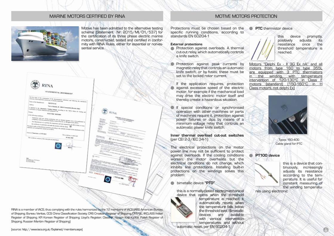
bimetallic device “PtO”
this is a normally-closed electromechanical device that opens when the threshold
temperature is reached; it automatically resets when the temperature falls below the threshold level. Bimetallic devices are available with various intervention temperatures and without
automatic reset, per EN 60204-1.
Motive has been admitted to the alternative testing scheme (Statement Nr. 2015/MI/01/537) for the certification of its three phase electric marine motors, constructed, tested and certified in confor-mity with RINA Rules, either for essential or non-es-sential service.
RINA is a member of IACS, thus complying with the rules harmonized by the 12 members of IACS (ABS American Bureau of Shipping; Bureau Veritas, CCS China Classification Society; CRS Croatian Register of Shipping; DNV-Gl; IRClASS Indian Register of Shipping; KR Korean Register of Shipping; lloyd’s Register; ClassNK Nippon Kaiji Kyokai; Polish Register of Shipping; Russian Maritim Register of Shipping)
(source: http://www.iacs.org.uk/Explained/members.aspx)
PtC thermistor device
this device promptly,positively adjusts itsresistance once thethreshold temperature is reached.
Motors “Delphi Ex - II 3G Ex nA” and allmotors from type 160 to type 355lare equipped with 3 PTC thermistorsin the winding, with temperatureintervention of 120-130°C in Class Fmotors (standard) (150-160°C in HClass motors, not delphi Ex)
Types 160-400Cable gland for PTC
Pt100 device
this is a device that con-tinuously, increasingly adjusts its resistance according to the tem-perature. It is useful for constant measuring of the winding temperatu-
res using electronic
11
N
a
b
c
d
Tmax0
1
2
3
4
5
6
7
DUTY SERVICE
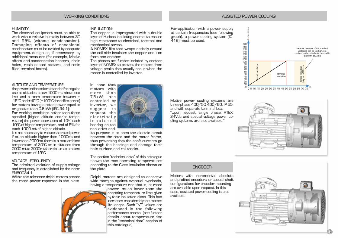
All Motive motors shown in this catalogue aremade for S1 continuous duty service, as perIEC 34-1 norm. The duty service class is shownon the rating plate.Below are described the various types ofservice:S1 - Continuous service: operating at constantload of duration N in order to reach a thermalbalance.
S2 - Limited-duration service.S3 - Periodic intermittent service.S4 - Periodic intermittent service with start-
up.S5 - Periodic intermittent service with electric
braking.S6 - Uninterrupted periodic service with
intermittent load.S7 - Uninterrupted periodic service with
electric braking.S8 - Uninterrupted periodic service with
correlated load and velocity variations.S9 - Service with non-periodic variations in
load and speed.
no protection
protection againstsolid corps biggerthan 50mm
protection againstsolid corps biggerthan 12mm
protection againstsolid corps biggerthan a 2,5mm
protection againstsolid corps biggerthan 1 mm
protection againstharmful dustdeposits
complete protectionagainst the totalpenetration of dust
no protection
protection againstvertical water drops
protection againstwater drops fall upto 15° of inclination
protection againstwater drops up to60° of inclination
protection againstwater sprayed byall directions
protection against waterlaunched by a nozzle of6,3mm D with a watercapacity 12,5lt/min ata distance of maximum3 mt for 3 min
protection against waterprojections similar tosea waves
protection fromtemporary submersionin water, up to 1 meterin depth
protection fromextended periods ofimmersion, up to aspecific depth
1° number 2° number
The protection against people accidentalcontacts and/or the entry of corps and/orthe entry of water is expressed at internationallevel (EN60529) by a symbolic acronymcomposed by a group of 2 letters and 2numbers.
IP index of protection reference letters
1° num. Protection of people against contactsand protection against the entry of solid corps
2° num. Protection against harmful entry ofwater
Motive motors are IP55 protected
PROTECTION TYPE
a = loadb = electric lossesc = temperatured = timeN = steady load operating timeTmax= max temperature achieved
RAIN SHIELD OR CLEAN FLOW FAN COWLFOR TEXTILE INDUSTRYFor outdoor applications with V5 - V18 - V1 - V15installation, we recommend to mount a rain shield.This configuration may also be used in textilesprocessing industry.
TYPE63718090S90L100112132S132M160M160L180M180L200L225S225M250M280S280M315S315M315L355M355L400
L215323369403428469453573613770825915955
102511551160122012651315154015701680184018702290O
PTI
ON
AL
OPTI
ON
AL
OPTI
ON
AL
STAN
DARD
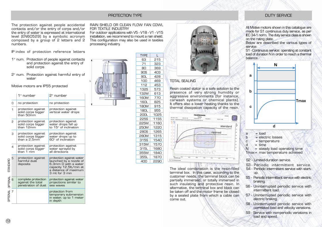
TOTAL SEALING
Resin coated stator is a safe solution to thepresence of very strong humidity oraggressive environments (for instance,carwash systems or chemical plants).It offers also a lower heating thanks to thethermal dissipation capacity of the resin.
The ideal combination is the resin-filledterminal box. In this case, according to thecustomer needs, the terminal block can bepartially immersed, or totally immersed insuch insulating and protective resin. Inalternative, the terminal box and block canbe taken off and the motor frame be closedby a sealed plate from which a cable cancome out.
Note: rotors are painted against oxidationas a standard
standard
resined
DUTY SERVICE
All Motive motors shown in this catalogue aremade for S1 continuous duty service, as perIEC 34-1 norm. The duty service class is shownon the rating plate.Below are described the various types ofservice:S1 - Continuous service: operating at constantload of duration N in order to reach a thermalbalance.
S2 - Limited-duration service.S3 - Periodic intermittent service.S4 - Periodic intermittent service with start-
up.S5 - Periodic intermittent service with electric
braking.S6 - Uninterrupted periodic service with
intermittent load.S7 - Uninterrupted periodic service with
electric braking.S8 - Uninterrupted periodic service with
correlated load and velocity variations.S9 - Service with non-periodic variations in
load and speed.
no protection
protection againstsolid corps biggerthan 50mm
protection againstsolid corps biggerthan 12mm
protection againstsolid corps biggerthan a 2,5mm
protection againstsolid corps biggerthan 1 mm
protection againstharmful dustdeposits
complete protectionagainst the totalpenetration of dust
no protection
protection againstvertical water drops
protection againstwater drops fall upto 15° of inclination
protection againstwater drops up to60° of inclination
protection againstwater sprayed byall directions
protection against waterlaunched by a nozzle of6,3mm D with a watercapacity 12,5lt/min ata distance of maximum3 mt for 3 min
protection against waterprojections similar tosea waves
protection fromtemporary submersionin water, up to 1 meterin depth
protection fromextended periods ofimmersion, up to aspecific depth
1° number 2° number
The protection against people accidentalcontacts and/or the entry of corps and/orthe entry of water is expressed at internationallevel (EN60529) by a symbolic acronymcomposed by a group of 2 letters and 2numbers.
IP index of protection reference letters
1° num. Protection of people against contactsand protection against the entry of solid corps
2° num. Protection against harmful entry ofwater
Motive motors are IP55 protected
PROTECTION TYPE
a = loadb = electric lossesc = temperatured = timeN = steady load operating timeTmax= max temperature achieved
RAIN SHIELD OR CLEAN FLOW FAN COWLFOR TEXTILE INDUSTRYFor outdoor applications with V5 - V18 - V1 - V15installation, we recommend to mount a rain shield.This configuration may also be used in textilesprocessing industry.
TYPE63718090S90L100112132S132M160M160L180M180L200L225S225M250M280S280M315S315M315L355M355L400
L215323369403428469453573613770825915955
102511551160122012651315154015701680184018702290O
PTI
ON
AL
OPTI
ON
AL
OPTI
ON
AL
STAN
DARD
TOTAL SEALING
Resin coated stator is a safe solution to thepresence of very strong humidity oraggressive environments (for instance,carwash systems or chemical plants).It offers also a lower heating thanks to thethermal dissipation capacity of the resin.
The ideal combination is the resin-filledterminal box. In this case, according to thecustomer needs, the terminal block can bepartially immersed, or totally immersed insuch insulating and protective resin. Inalternative, the terminal box and block canbe taken off and the motor frame be closedby a sealed plate from which a cable cancome out.
Note: rotors are painted against oxidationas a standard
standard
resined
12
WORKING CONDITIONS
HUMIDITY:The electrical equipment must be able towork with a relative humidity between 30and 95% (without condensation).Damaging ef fects of occasionalcondensation must be avoided by adequateequipment design or, if necessary, byadditional measures (for example, Motiveoffers anti-condensation heaters, drainholes, resin coated stators, and resinfilled terminal boxes).
ALTITUDE AND TEMPERATURE:the powers indicated are intended for regularuse at altitudes below 1000 mt above sealevel and a room temperature between +5°Cand +40°C for motors having a rated powerbelow 0.6 kW, or between -15°C and 40°Cfor motors having a rated power equal toor greater than 0.6 kW (IEC 34-1): Forworking conditionsrather than those specified (higher altitudeand/or temperature) the power decreasesof 10% each 10°C of higher temperature,and of 8% for each 1000 mt of higheraltitude.It is not necessary to reduce the rated powerif at an altitude higher than 1000mt andlower than 2000mt there is a max ambienttemperature of 30°C or, in altitudes from2000 mt to 3000mt there is a max ambienttemperature of 19°C.
VOLTAGE - FREQUENCY:The admitted variation of supply voltageand frequency is established by the normEN60034-1Within this tolerance delphi motors providethe rated power reported in the plate.
ASSISTED POWER COOLING
Motors with encoder or special shaftconfigurations for encoder mountingare available upon request. In thiscase, assisted power cooling is alsoavailable, supported by brackets onthe fan cover
For application with a power supplyat certain frequencies (see followinggraph), a power cooling system (IC-416) must be used.
INSULATION:The copper is impregnated with a doublelayer of H class insulating enamel to ensurehigh resistance to electrical, thermal andmechanical stress.A NOMEX film that wraps entirely aroundthe coil side insulates the copper and ironfrom one another.The phases are further isolated by anotherlayer of NOMEX to protect the motors fromvoltage peaks that usually occur when themotor is controlled by inverter.
In case thatmotors withm o r e t h a n7 5 k W a r econtrolled byinver ter, werecommend torequest thee l e c t r i c a l l yi n s u l a t e dbearing on thenon drive end.Its purpose is to open the electric circuitbetween the rotor and the motor frame,thus preventing that the shaft currents gothrough the bearings and damage theirballs surface and roll tracks.
The section “technical data” of this catalogueshows the max operating temperaturesaccording to the Class insulation shown onthe plate.
Delphi motors are designed to conservewide margins against eventual overloads,having a temperature rise that is, at rated
power, much lower than theoperating temperature limit givenby their insulation class. This factincreases considerably the motorslife lenght. Such "ΔT" values areevidenced in the fol lowingperformance charts. (see furtherdetails about temperature risein the “technical data” section ofthis catalogue)
forc
ed v
entil
atio
n
forc
ed v
entil
atio
n(o
nly
for
n>36
00 r
pm)
Motive power cooling systems arethree-phase 400/50 400/60, IP55, and with separate terminal box.Upon request, single phase and specialvoltage power cooling systems arealso available.
standardventilation
because the noise of the standardventilation can be too high, not
conform to the noise limits reported inthe norm IEC 34-9
% o
f ven
tilat
ion
ENCODER
In case thatmotors withm o r e t h a n7 5 k W a r econtrolled byinverter, wesuggest torequest thee l e c t r i c a l l yi n s u l a t e dbearing on thenon drive end.
AlTITUDE AND TEMPERATURE:the powers indicated are intended for regularuse at altitudes below 1000 mt above sealevel and a room temperature between + -15°C and +40°C (+100°C for delfire series)for motors having a rated power equal toor greater than 0.6 kW (IEC 34-1): For working conditions rather than those specified (higher altitude and/or tempe-rature) the power decreases of 10% each 10°C of higher temperature, and of 8% for each 1000 mt of higher altitude.It is not necessary to reduce the rated powerif at an altitude higher than 1000mt andlower than 2000mt there is a max ambienttemperature of 30°C or, in altitudes from2000 mt to 3000mt there is a max ambienttemperature of 19°C.
Motive power cooling systems are three-phase 400/50 400/60, IP 55, and with separate terminal box."Upon request, single phase, ATEX, 24Vdc and special voltage power co-oling systems are also available."
Motors with incremental, absolute and profinet encoders or special shaftconfigurations for encoder mountingare available upon request. In thiscase, assisted power cooling is alsoavailable.
13
56-132
50±5%
230 400
220 380
240 415
60±5%
260 440
220 380
265 460
280 480
112-355
50±5%
400 690
380 660
415 720
60±5%
440 760
380 660
460 795
480 830
DELTA CONNECTIONDelta connection is obtained by connecting the end of aphase with the beginning of the following one.The phase current Iph and the phase voltage Uph arerepectively:Iph = In / 3 -2Uph = Unwhere In and Un are referred to Delta connection.
WIRING DIAGRAMS
Motive three phase motors can be connected “Star” or “Delta”.
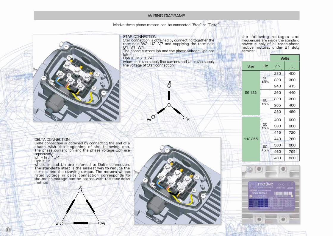
STAR CONNECTIONStar connection is obtained by connecting together theterminals W2, U2, V2 and supplying the terminalsU1, V1, W1.The phase current and voltage are respectively:Iph = InUph = Un / 3 -2where In is the supply line current and Un is the supplyline voltage of Star connection
the fo l lowing vo l tages andfrequencies are inside the standardpower supply of all three-phasemotive motors, under S1 dutyservice:
Size
Volts
Hz
STAR CONNECTIONStar connection is obtained by connecting together theterminals W2, U2, V2 and supplying the terminalsU1, V1, W1.The phase current Iph and the phase voltage Uph areIph = InUph = Un / 1,74where In is the supply line current and Un is the supplyline voltage of Star connection
DElTA CONNECTIONDelta connection is obtained by connecting the end of aphase with the beginning of the following one. The phase current Iph and the phase voltage Uph are repectively:Iph = In / 1,74 Uph = Unwhere In and Un are referred to Delta connection.The star-delta start is the easiest way to reduce the current and the starting torque. The motors whose rated voltage in delta connection corresponds to the mains voltage can be stared with the star-delta method
14
U2
U1
U1
U1
U2
V2
V1
V1
V1
V2
W2
W1
W1
W1
W2
High-speed connection
Low-speed connection
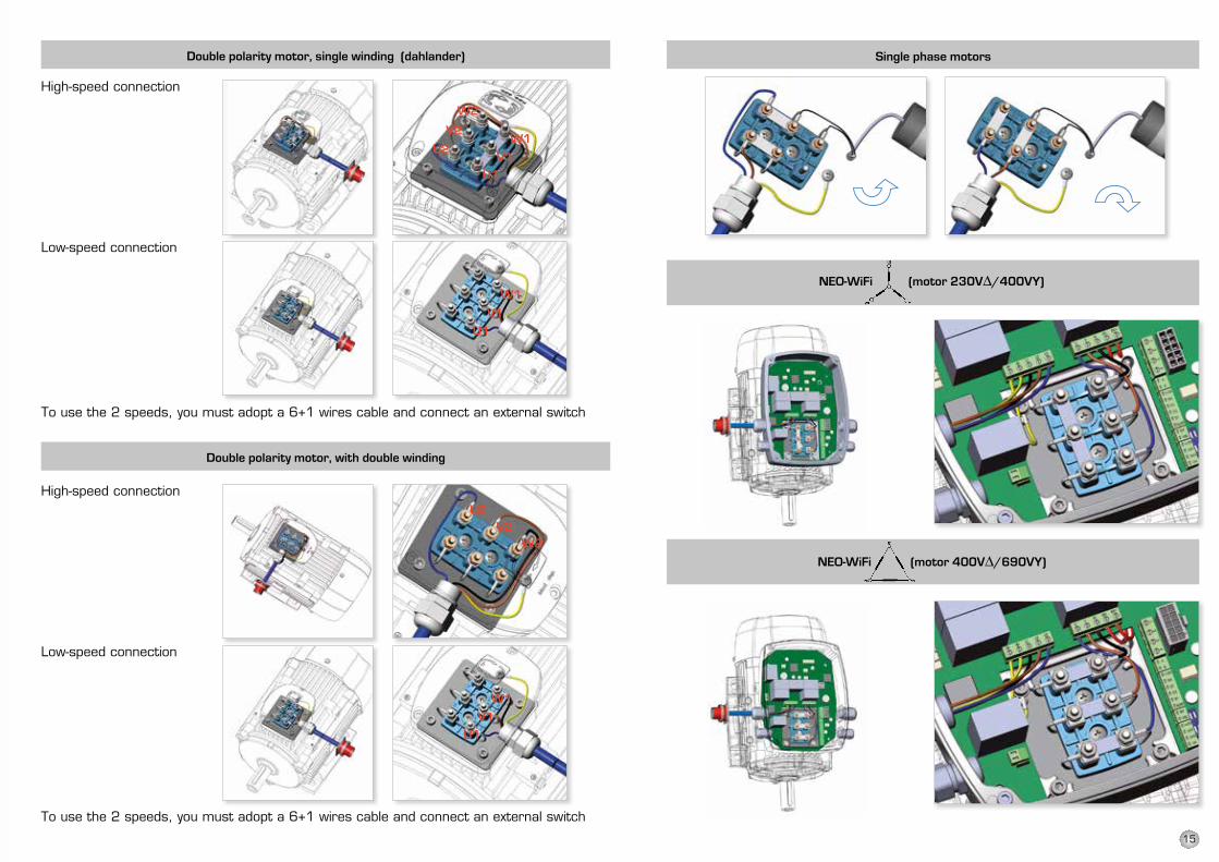
Double polarity motor, single winding (dahlander) Single phase motors
NEO-WiFi (motor 400VΔ/690VY)
NEO-WiFi (motor 230VΔ/400VY)
To use the 2 speeds, you must adopt a 6+1 wires cable and connect an external switch
Double polarity motor, with double winding
To use the 2 speeds, you must adopt a 6+1 wires cable and connect an external switch
High-speed connection
Low-speed connection
15
ATDC AT24 ATDCAT24
ATTD ATTD24
ATTD=ATDCx2
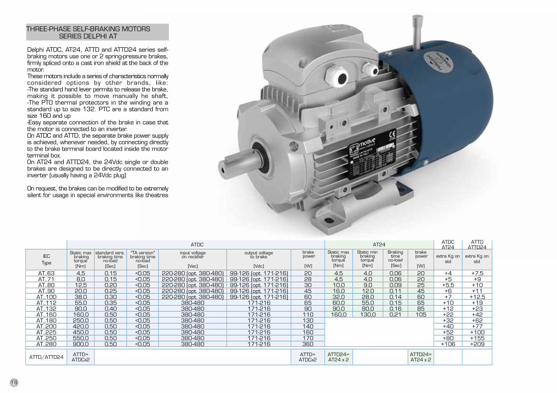
AT..63 4,5 0,15 <0,05 220-280 (opt. 380-480) 99-126 (opt. 171-216) 20 4,5 4,0 0,06 20 +4 +7,5AT..71 8,0 0,15 <0,05 220-280 (opt. 380-480) 99-126 (opt. 171-216) 28 4,5 4,0 0,06 20 +5 +9AT..80 12,5 0,20 <0,05 220-280 (opt. 380-480) 99-126 (opt. 171-216) 30 10,0 9,0 0,09 25 +5,5 +10AT..90 20,0 0,25 <0,05 220-280 (opt. 380-480) 99-126 (opt. 171-216) 45 16,0 12,0 0,11 45 +6 +11
AT..100 38,0 0,30 <0,05 220-280 (opt. 380-480) 99-126 (opt. 171-216) 60 32,0 28,0 0,14 60 +7 +12,5AT..112 55,0 0,35 <0,05 380-480 171-216 65 60,0 55,0 0,15 65 +10 +19AT..132 90,0 0,40 <0,05 380-480 171-216 90 90,0 80,0 0,16 85 +12 +23AT..160 160,0 0,50 <0,05 380-480 171-216 110 160,0 130,0 0,21 105 +22 +42AT..180 250,0 0,50 <0,05 380-480 171-216 130 +32 +62AT..200 420,0 0,50 <0,05 380-480 171-216 140 +40 +77AT..225 450,0 0,50 <0,05 380-480 171-216 160 +52 +100AT..250 550,0 0,50 <0,05 380-480 171-216 170 +80 +155AT..280 900,0 0,50 <0,05 380-480 171-216 360 +106 +209
ATTD/ATTD24 ATTD=ATDCx2
ATTD24=AT24 x 2
ATTD24=AT24 x 2
DELPHI AT
Delphi ATDC, AT24, ATTD and ATTD24 series self-braking motors use one or 2 spring-pressure brakes,firmly spliced onto a cast iron shield at the back of themotor.These motors include a series of characteristics normallyconsidered options by other brands, like:-The standard hand lever permits to release the brake,making it possible to move manually he shaft,-The PTO thermal protectors in the winding are astandard up to size 132. PTC are a standard fromsize 160 and up-Easy separate connection of the brake in case thatthe motor is connected to an inverter.On ATDC and ATTD, the separate brake power supplyis achieved, whenever needed, by connecting directlyto the brake terminal board located inside the motorterminal box.On AT24 and ATTD24, the 24Vdc single or doublebrakes are designed to be directly connected to aninverter (usually having a 24Vdc plug)
On request, the brakes can be modified to be extremelysilent for usage in special environments like theatres
Static minbrakingtorque[Nm]
Brakingtime
no-load [Sec]
IECType
Static maxbrakingtorque[Nm]
standard vers.braking time
no-load[Sec]
output voltageto brake
[Vdc]
Static max brakingtorque[Nm)
input voltageon rectifier
[Vac]
extra Kg onstd
extra Kg onstd
"TA version"braking time
no-load[Sec]
brake power
[W]
brake power
[W]
THREE-PHASE SElF-BRAKING MOTORSSERIES DElPHI AT
16
AT24
ATTD24
ATTD
SATDCDELPHI AT
Delphi ATDC, AT24, ATTD and ATTD24 series self-braking motors use one or 2 spring-pressure brakes,firmly spliced onto a cast iron shield at the back of themotor.These motors include a series of characteristics normallyconsidered options by other brands, like:-The standard hand lever permits to release the brake,making it possible to move manually he shaft,-The PTO thermal protectors in the winding are astandard up to size 132. PTC are a standard fromsize 160 and up-Easy separate connection of the brake in case thatthe motor is connected to an inverter.On ATDC and ATTD, the separate brake power supplyis achieved, whenever needed, by connecting directlyto the brake terminal board located inside the motorterminal box.On AT24 and ATTD24, the 24Vdc single or doublebrakes are designed to be directly connected to aninverter (usually having a 24Vdc plug)
On request, the brakes can be modified to be extremelysilent for usage in special environments like theatres
Static minbrakingtorque[Nm]
Brakingtime
no-load [Sec]
IECType
Static maxbrakingtorque[Nm]
standard vers.braking time
no-load[Sec]
output voltageto brake
[Vdc]
Static max brakingtorque[Nm)
input voltageon rectifier
[Vac]
extra Kg onstd
extra Kg onstd
"TA version"braking time
no-load[Sec]
brake power
[W]
brake power
[W]
BRAKE DESCRIPTION BRAKE OPERATION ADJUSTMENT
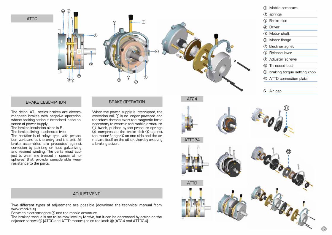
The adjustment is made by using thethreaded bushes �, using a thicknessgauge to make sure that the wished airgap is reached.
Braking torque adjustmentThe braking torque is set to its max level by Motive, but it can be decreased by actingon the adjuster screws � (ATDC and ATTD motors) or on the knob � (AT24 andATTD24).
Two different types of adjustment are possible
S air gap adjustmentFor proper operation, the air gap S between electromagnet � and the mobile armature� must be between the following indicated limits:
When the power supply is interrupted, theexcitation coil � is no longer powered andtherefore doesn’t exert the magnetic forcenecessary to restrain the mobile armature�, hwich, pushed by the pressure springs�, compresses the brake disk � againstthe motor flange � on one side and thearmature itself on the other, thereby creatinga braking action.
The delphi AT... series brakes areelectromagnetic brakes with negativeoperation, whose braking action is exercisedin the absence of power supply.The brakes insulation class is F.The brakes lining is asbestos-free.The rectifier is of relays type, with protectionvaristors at the entry and the exit. All brakeassemblies are protected against corrosionby painting or heat galvanizing and resinedwinding. The parts most subject to wearare treated in special atmospheres thatprovide considerable wear resistance tothe parts.
Mobile armature
springs
Brake disc
Driver
Motor shaft
Motor flange
Electromagnet
Release lever
Adjuster screws
Threaded bush
braking torque setting knob
ATTD connection plate
Air gap
MOTOR TYPE S AIR GAP (mm)
63˜71 0.40˜0.50
80˜160 0.50˜0.60
BRAKE DESCRIPTION BRAKE OPERATION ADJUSTMENT
The adjustment is made by using thethreaded bushes �, using a thicknessgauge to make sure that the wished airgap is reached.
Braking torque adjustmentThe braking torque is set to its max level by Motive, but it can be decreased by actingon the adjuster screws � (ATDC and ATTD motors) or on the knob � (AT24 andATTD24).
Two different types of adjustment are possible
S air gap adjustmentFor proper operation, the air gap S between electromagnet � and the mobile armature� must be between the following indicated limits:
When the power supply is interrupted, theexcitation coil � is no longer powered andtherefore doesn’t exert the magnetic forcenecessary to restrain the mobile armature�, hwich, pushed by the pressure springs�, compresses the brake disk � againstthe motor flange � on one side and thearmature itself on the other, thereby creatinga braking action.
The delphi AT... series brakes areelectromagnetic brakes with negativeoperation, whose braking action is exercisedin the absence of power supply.The brakes insulation class is F.The brakes lining is asbestos-free.The rectifier is of relays type, with protectionvaristors at the entry and the exit. All brakeassemblies are protected against corrosionby painting or heat galvanizing and resinedwinding. The parts most subject to wearare treated in special atmospheres thatprovide considerable wear resistance tothe parts.
Mobile armature
springs
Brake disc
Driver
Motor shaft
Motor flange
Electromagnet
Release lever
Adjuster screws
Threaded bush
braking torque setting knob
ATTD connection plate
Air gap
MOTOR TYPE S AIR GAP (mm)
63˜71 0.40˜0.50
80˜160 0.50˜0.60
The delphi AT... series brakes are electro-magnetic brakes with negative operation, whose braking action is exercised in the ab-sence of power supply.The brakes insulation class is F.The brakes lining is asbestos-free.The rectifier is of relays type, with protec-tion varistors at the entry and the exit. All brake assemblies are protected against corrosion by painting or heat galvanizing and resined winding. The parts most sub-ject to wear are treated in special atmo-spheres that provide considerable wear resistance to the parts.
When the power supply is interrupted, the excitation coil is no longer powered and therefore doesn’t exert the magnetic force necessary to restrain the mobile armature
, hwich, pushed by the pressure springs , compresses the brake disk against
the motor flange on one side and the ar-mature itself on the other, thereby creating a braking action.
Two different types of adjustment are possible (download the technical manual from www.motive.it)Between electromagnet and the mobile armature.The braking torque is set to its max level by Motive, but it can be decreased by acting on the adjuster screws (ATDC and ATTD motors) or on the knob (AT24 and ATTD24).
17
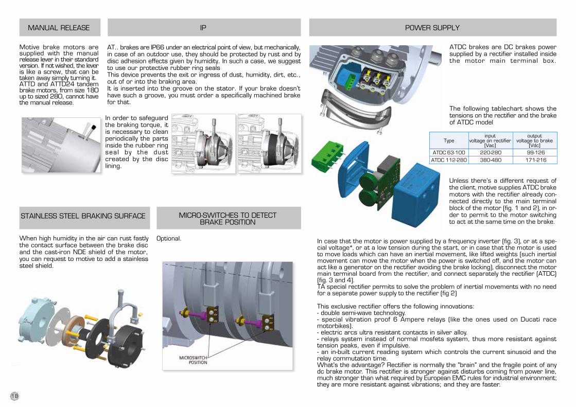
ATDC 63-100 220-280 99-126 ATDC 112-280 380-480 171-216
MANUAL RELEASE
Motive brake motors aresupplied with the manualrelease lever in their standardversion. If not wished, the leveris like a screw, that can betaken away simply turning it.ATTD and ATTD24 tandembrake motors, from size 180up to sized 280, cannot havethe manual release.
IP
AT.. brakes are IP66 under an electrical point of view, but mechanically,in case of an outdoor use, they should be protected by rust and bydisc adhesion effects given by humidity. In such a case, we suggestto use our protective rubber ring sealsThis device prevents the exit or ingress of dust, humidity, dirt, etc.,out of or into the braking area.It is inserted into the groove on the stator. If your brake doesn’thave such a groove, you must order a specifically machined brakefor that.
STAINLESS STEEL BRAKING SURFACE
When high humidity in the air can rust fastlythe contact surface between the brake discand the cast-iron NDE shield of the motor,you can request to motive to add a stainlesssteel shield.
MICRO-SWITCHES TO DETECTBRAKE POSITION
Optional.
In order to safeguardthe braking torque, itis necessary to cleanperiodically the partsinside the rubber ringseal by the dustcreated by the disclining.
POWER SUPPLY
ATDC brakes are DC brakes powersupplied by a rectifier installed insidethe motor main terminal box.
The following tablechart shows thetensions on the rectifier and the brakeof ATDC model
Unless there’s a different request ofthe client, motive supplies ATDC brakemotors with the rectifier alreadyconnected directly to the main terminalblock of the motor (fig. 1, 2, 3 and4), in order to permit to the motorswitching to act at the same time onthe brake.
inputvoltage on rectifier
[Vac]
outputvoltage to brake
[Vdc]Type
In case that the motor is power supplied by a frequency inverter (fig. 5a and 5b),or at a special voltage*, or at a low tension during the start, or in case that themotor is used to move loads which can have an inertial movement, like lifted weights(such inertial movement can move the motor when the power is switched off, andthe motor can act like a generator on the rectifier avoiding the brake locking),disconnect the motor main terminal board from the rectifier, and connect separatelythe rectifier (ATDC) (fig. 5a, 5b, 6 and 7).TA special rectifier permits to solve the problem of inertial movements with no needfor a separate power supply to the rectifier (fig 3 and 4)
This exclusive rectifier offers the following innovations:- double semi-wave technology.- special vibration proof 6 Ampere relays (like the ones used on Ducati racemotorbikes).- electric arcs ultra resistant contacts in silver alloy.- relays system instead of normal mosfets system, thus more resistant againsttension peaks, even if impulsive.- an in-built current reading system which controls the current sinusoid and therelay commutation time.What's the advantage? Rectifier is normally the "brain" and the fragile point of anydc brake motor. This rectifier is stronger against disturbs coming from power line,much stronger than what required by European EMC rules for industrial environment;they are more resistant against vibrations; and they are faster.
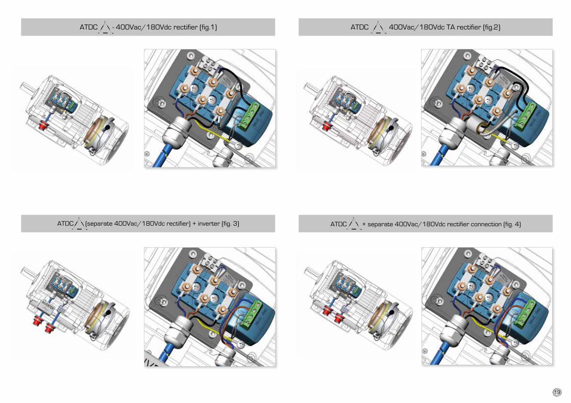
Unless there’s a different request of the client, motive supplies ATDC brakemotors with the rectifier already con-nected directly to the main terminal block of the motor (fig. 1 and 2), in or-der to permit to the motor switching to act at the same time on the brake.
In case that the motor is power supplied by a frequency inverter (fig. 3), or at a spe-cial voltage*, or at a low tension during the start, or in case that the motor is used to move loads which can have an inertial movement, like lifted weights (such inertial movement can move the motor when the power is switched off, and the motor can act like a generator on the rectifier avoiding the brake locking), disconnect the motor main terminal board from the rectifier, and connect separately the rectifier (ATDC) (fig. 3 and 4).TA special rectifier permits to solve the problem of inertial movements with no need for a separate power supply to the rectifier (fig 2)
18
MANUAL RELEASE
Motive brake motors aresupplied with the manualrelease lever in their standardversion. If not wished, the leveris like a screw, that can betaken away simply turning it.ATTD and ATTD24 tandembrake motors, from size 180up to sized 280, cannot havethe manual release.
IP
AT.. brakes are IP66 under an electrical point of view, but mechanically,in case of an outdoor use, they should be protected by rust and bydisc adhesion effects given by humidity. In such a case, we suggestto use our protective rubber ring sealsThis device prevents the exit or ingress of dust, humidity, dirt, etc.,out of or into the braking area.It is inserted into the groove on the stator. If your brake doesn’thave such a groove, you must order a specifically machined brakefor that.
STAINLESS STEEL BRAKING SURFACE
When high humidity in the air can rust fastlythe contact surface between the brake discand the cast-iron NDE shield of the motor,you can request to motive to add a stainlesssteel shield.
MICRO-SWITCHES TO DETECTBRAKE POSITION
Optional.
In order to safeguardthe braking torque, itis necessary to cleanperiodically the partsinside the rubber ringseal by the dustcreated by the disclining.
POWER SUPPLY
ATDC brakes are DC brakes powersupplied by a rectifier installed insidethe motor main terminal box.
The following tablechart shows thetensions on the rectifier and the brakeof ATDC model
Unless there’s a different request ofthe client, motive supplies ATDC brakemotors with the rectifier alreadyconnected directly to the main terminalblock of the motor (fig. 1, 2, 3 and4), in order to permit to the motorswitching to act at the same time onthe brake.
inputvoltage on rectifier
[Vac]
outputvoltage to brake
[Vdc]Type
In case that the motor is power supplied by a frequency inverter (fig. 5a and 5b),or at a special voltage*, or at a low tension during the start, or in case that themotor is used to move loads which can have an inertial movement, like lifted weights(such inertial movement can move the motor when the power is switched off, andthe motor can act like a generator on the rectifier avoiding the brake locking),disconnect the motor main terminal board from the rectifier, and connect separatelythe rectifier (ATDC) (fig. 5a, 5b, 6 and 7).TA special rectifier permits to solve the problem of inertial movements with no needfor a separate power supply to the rectifier (fig 3 and 4)
This exclusive rectifier offers the following innovations:- double semi-wave technology.- special vibration proof 6 Ampere relays (like the ones used on Ducati racemotorbikes).- electric arcs ultra resistant contacts in silver alloy.- relays system instead of normal mosfets system, thus more resistant againsttension peaks, even if impulsive.- an in-built current reading system which controls the current sinusoid and therelay commutation time.What's the advantage? Rectifier is normally the "brain" and the fragile point of anydc brake motor. This rectifier is stronger against disturbs coming from power line,much stronger than what required by European EMC rules for industrial environment;they are more resistant against vibrations; and they are faster.
ATDC - 400Vac/180Vdc rectifier (fig.1)
ATDC (separate 400Vac/180Vdc rectifier) + inverter (fig. 3)
ATDC 400Vac/180Vdc TA rectifier (fig.2)
ATDC + separate 400Vac/180Vdc rectifier connection (fig. 4)
19
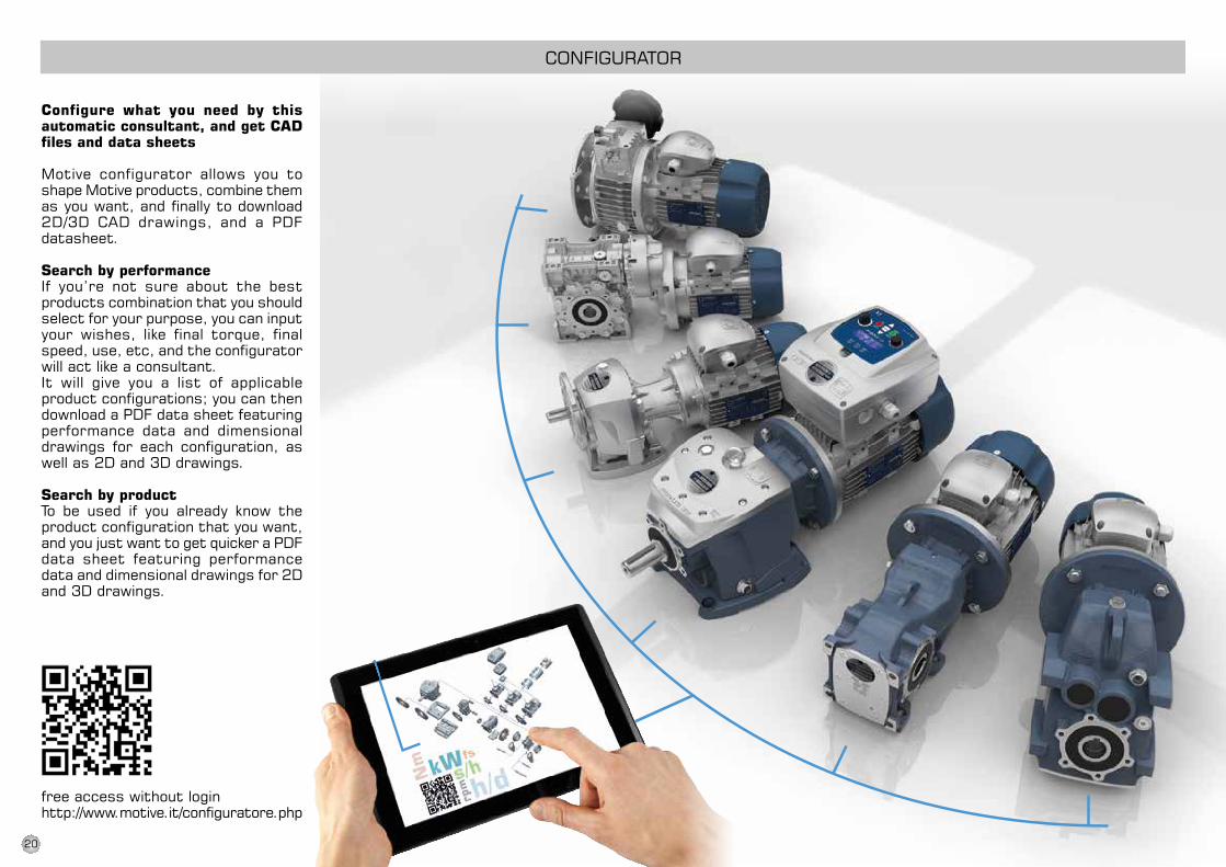
Configure what you need by this automatic consultant, and get CAD files and data sheets
Motive configurator allows you to shape Motive products, combine them as you want, and finally to download 2D/3D CAD drawings, and a PDF datasheet.
Search by performanceIf you’re not sure about the best products combination that you should select for your purpose, you can input your wishes, like final torque, final speed, use, etc, and the configurator will act like a consultant.It will give you a list of applicable product configurations; you can then download a PDF data sheet featuring performance data and dimensional drawings for each configuration, as well as 2D and 3D drawings.
Search by productTo be used if you already know the product configuration that you want, and you just want to get quicker a PDF data sheet featuring performance data and dimensional drawings for 2D and 3D drawings.
free access without loginhttp://www.motive.it/configuratore.php
ConFIgurATor
20
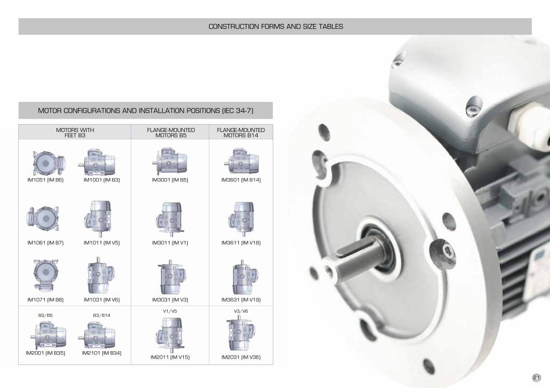
IM1051 (IM B6) IM1001 (IM B3) IM3001 (IM B5) IM3601 (IM B14)
IM1061 (IM B7) IM1011 (IM V5) IM3011 (IM V1) IM3611 (IM V18)
IM1071 (IM B8) IM1031 (IM V6) IM3031 (IM V3) IM3631 (IM V19)
B3/B5 B3/B14V1/V5 V3/V6
IM2001 (IM B35) IM2101 (IM B34)IM2011 (IM V15) IM2031 (IM V36)
FLANGE-MOUNTEDMOTORS B14
FLANGE-MOUNTEDMOTORS B5
MOTORS WITHFEET B3
CONSTRUCTION FORMS AND SIZE TABLES
MOTOR CONFIGURATIONS AND INSTALLATION POSITIONS (IEC 34-7)
21
no ATDC/ATTD ATDC/ATTDie2 ie3 B3 B5 B14 B5r / B14B
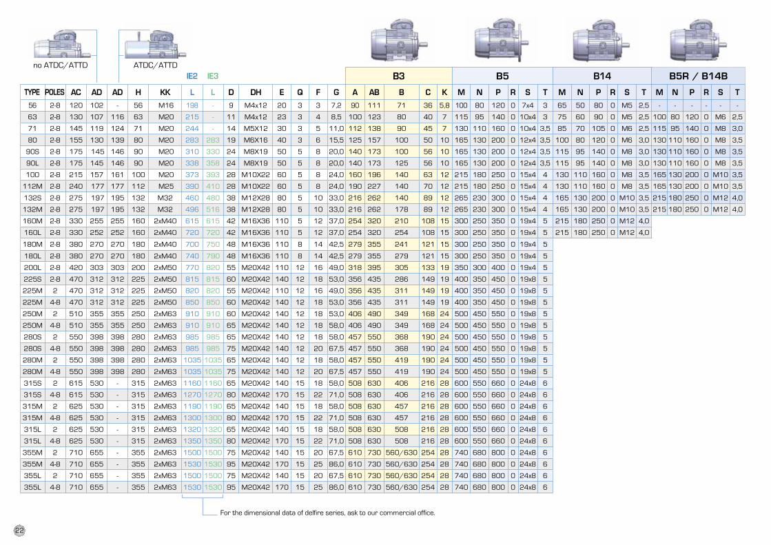
AC Ad Ad H KK L L d dH e Q F g A AB B C K M n P r s t M n P r s t M n P r s t
56 2-8 120 102 - 56 M16 198 - 9 M4x12 20 3 3 7,2 90 111 71 36 5,8 100 80 120 0 7x4 3 65 50 80 0 M5 2,5 - - - - - -
63 2-8 130 107 116 63 M20 215 - 11 M4x12 23 3 4 8,5 100 123 80 40 7 115 95 140 0 10x4 3 75 60 90 0 M5 2,5 100 80 120 0 M6 2,5
71 2-8 145 119 124 71 M20 244 - 14 M5X12 30 3 5 11,0 112 138 90 45 7 130 110 160 0 10x4 3,5 85 70 105 0 M6 2,5 115 95 140 0 M8 3,0
80 2-8 155 130 139 80 M20 283 283 19 M6X16 40 3 6 15,5 125 157 100 50 10 165 130 200 0 12x4 3,5 100 80 120 0 M6 3,0 130 110 160 0 M8 3,5
90S 2-8 175 145 146 90 M20 310 330 24 M8X19 50 5 8 20,0 140 173 100 56 10 165 130 200 0 12x4 3,5 115 95 140 0 M8 3,0 130 110 160 0 M8 3,5
90l 2-8 175 145 146 90 M20 338 358 24 M8X19 50 5 8 20,0 140 173 125 56 10 165 130 200 0 12x4 3,5 115 95 140 0 M8 3,0 130 110 160 0 M8 3,5
100 2-8 215 157 161 100 M20 373 393 28 M10X22 60 5 8 24,0 160 196 140 63 12 215 180 250 0 15x4 4 130 110 160 0 M8 3,5 165 130 200 0 M10 3,5
112M 2-8 240 177 177 112 M25 390 410 28 M10X22 60 5 8 24,0 190 227 140 70 12 215 180 250 0 15x4 4 130 110 160 0 M8 3,5 165 130 200 0 M10 3,5
132S 2-8 275 197 195 132 M32 460 480 38 M12X28 80 5 10 33,0 216 262 140 89 12 265 230 300 0 15x4 4 165 130 200 0 M10 3,5 215 180 250 0 M12 4,0
132M 2-8 275 197 195 132 M32 496 516 38 M12X28 80 5 10 33,0 216 262 178 89 12 265 230 300 0 15x4 4 165 130 200 0 M10 3,5 215 180 250 0 M12 4,0
160M 2-8 330 255 255 160 2xM40 615 615 42 M16X36 110 5 12 37,0 254 320 210 108 15 300 250 350 0 19x4 5 215 180 250 0 M12 4,0
160l 2-8 330 252 252 160 2xM40 720 720 42 M16X36 110 5 12 37,0 254 320 254 108 15 300 250 350 0 19x4 5 215 180 250 0 M12 4,0
180M 2-8 380 270 270 180 2xM40 700 750 48 M16X36 110 8 14 42,5 279 355 241 121 15 300 250 350 0 19x4 5
180l 2-8 380 270 270 180 2xM40 740 790 48 M16X36 110 8 14 42,5 279 355 279 121 15 300 250 350 0 19x4 5
200l 2-8 420 303 303 200 2xM50 770 820 55 M20X42 110 12 16 49,0 318 395 305 133 19 350 300 400 0 19x4 5
225S 2-8 470 312 312 225 2xM50 815 815 60 M20X42 140 12 18 53,0 356 435 286 149 19 400 350 450 0 19x8 5
225M 2 470 312 312 225 2xM50 820 820 55 M20X42 110 12 16 49,0 356 435 311 149 19 400 350 450 0 19x8 5
225M 4-8 470 312 312 225 2xM50 850 850 60 M20X42 140 12 18 53,0 356 435 311 149 19 400 350 450 0 19x8 5
250M 2 510 355 355 250 2xM63 910 910 60 M20X42 140 12 18 53,0 406 490 349 168 24 500 450 550 0 19x8 5
250M 4-8 510 355 355 250 2xM63 910 910 65 M20X42 140 12 18 58,0 406 490 349 168 24 500 450 550 0 19x8 5
280S 2 550 398 398 280 2xM63 985 985 65 M20X42 140 12 18 58,0 457 550 368 190 24 500 450 550 0 19x8 5
280S 4-8 550 398 398 280 2xM63 985 985 75 M20X42 140 12 20 67,5 457 550 368 190 24 500 450 550 0 19x8 5
280M 2 550 398 398 280 2xM63 1035 1035 65 M20X42 140 12 18 58,0 457 550 419 190 24 500 450 550 0 19x8 5
280M 4-8 550 398 398 280 2xM63 1035 1035 75 M20X42 140 12 20 67,5 457 550 419 190 24 500 450 550 0 19x8 5
315S 2 615 530 - 315 2xM63 1160 1160 65 M20X42 140 15 18 58,0 508 630 406 216 28 600 550 660 0 24x8 6
315S 4-8 615 530 - 315 2xM63 1270 1270 80 M20X42 170 15 22 71,0 508 630 406 216 28 600 550 660 0 24x8 6
315M 2 625 530 - 315 2xM63 1190 1190 65 M20X42 140 15 18 58,0 508 630 457 216 28 600 550 660 0 24x8 6
315M 4-8 625 530 - 315 2xM63 1300 1300 80 M20X42 170 15 22 71,0 508 630 457 216 28 600 550 660 0 24x8 6
315l 2 625 530 - 315 2xM63 1320 1320 65 M20X42 140 15 18 58,0 508 630 508 216 28 600 550 660 0 24x8 6
315l 4-8 625 530 - 315 2xM63 1350 1350 80 M20X42 170 15 22 71,0 508 630 508 216 28 600 550 660 0 24x8 6
355M 2 710 655 - 355 2xM63 1500 1500 75 M20X42 140 15 20 67,5 610 730 560/630 254 28 740 680 800 0 24x8 6
355M 4-8 710 655 - 355 2xM63 1530 1530 95 M20X42 170 15 25 86,0 610 730 560/630 254 28 740 680 800 0 24x8 6
355l 2 710 655 - 355 2xM63 1500 1500 75 M20X42 140 15 20 67,5 610 730 560/630 254 28 740 680 800 0 24x8 6
355l 4-8 710 655 - 355 2xM63 1530 1530 95 M20X42 170 15 25 86,0 610 730 560/630 254 28 740 680 800 0 24x8 6
tyPe POLes
For the dimensional data of delfire series, ask to our commercial office.
22
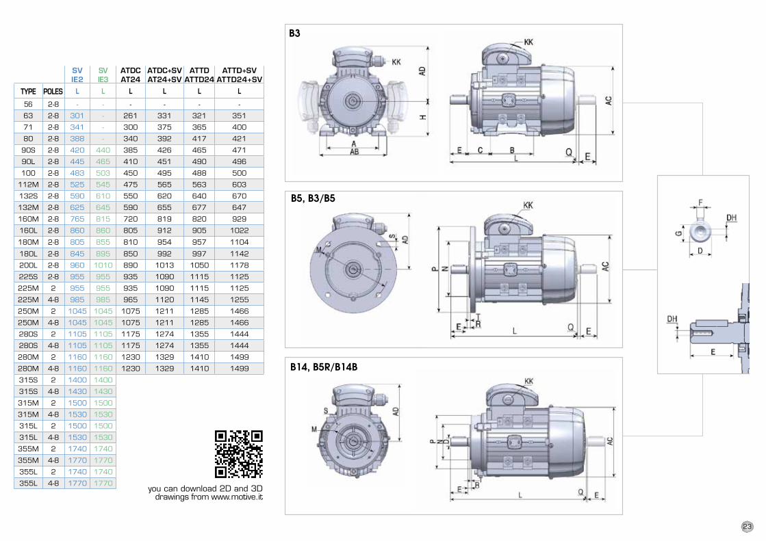
B3
B5, B3/B5
B14, B5R/B14B
SVIE2
SVIE3
ATDCAT24
ATDC+SVAT24+SV
ATTD ATTD24
ATTD+SVATTD24+SV
L L L L L L
56 2-8 - - - - - -
63 2-8 301 - 261 331 321 351
71 2-8 341 - 300 375 365 400
80 2-8 388 - 340 392 417 421
90S 2-8 420 440 385 426 465 471
90L 2-8 445 465 410 451 490 496
100 2-8 483 503 450 495 488 500
112M 2-8 525 545 475 565 563 603
132S 2-8 590 610 550 620 640 670
132M 2-8 625 645 590 655 677 647
160M 2-8 765 815 720 819 820 929
160L 2-8 860 860 805 912 905 1022
180M 2-8 805 855 810 954 957 1104
180L 2-8 845 895 850 992 997 1142
200L 2-8 960 1010 890 1013 1050 1178
225S 2-8 955 955 935 1090 1115 1125
225M 2 955 955 935 1090 1115 1125
225M 4-8 985 985 965 1120 1145 1255
250M 2 1045 1045 1075 1211 1285 1466
250M 4-8 1045 1045 1075 1211 1285 1466
280S 2 1105 1105 1175 1274 1355 1444
280S 4-8 1105 1105 1175 1274 1355 1444
280M 2 1160 1160 1230 1329 1410 1499
280M 4-8 1160 1160 1230 1329 1410 1499
315S 2 1400 1400
315S 4-8 1430 1430
315M 2 1500 1500
315M 4-8 1530 1530
315L 2 1500 1500
315L 4-8 1530 1530
355M 2 1740 1740
355M 4-8 1770 1770
355L 2 1740 1740
355L 4-8 1770 1770
TYPE POLES
you can download 2D and 3Ddrawings from www.motive.it
TypE poLES
23
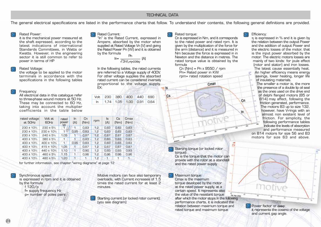
230 ± 10% 230 ± 5% 1 1 0,83 1,2 0,83 0,83 0,83230 ± 10% 230 ± 10% 1 0,95 0,83 1,2 0,83 0,83 0,83230 ± 10% 240 ± 5% 1,05 1 0,87 1,2 0,87 0,87 0,87400 ± 10% 380 ± 5% 1 1 0,83 1,2 0,83 0,83 0,83400 ± 10% 400 ± 10% 1 0,95 0,83 1,2 0,83 0,83 0,83400 ± 10% 415 ± 10% 1,05 1 0,87 1,2 0,87 0,87 0,87400 ± 10% 440 ± 10% 1,10 1 0,90 1,2 0,93 0,93 0,93400 ± 10% 460 ± 5% 1,15 1 0,96 1,2 0,96 0,96 0,96400 ± 10% 480 ± 5% 1,20 1 1 1,2 1 1 1
Volt 230 380 400 440 690
In 1,74 1,05 1,00 0,91 0,64
The general electrical specifications are listed in the performance charts that follow. To understand their contents, the following general definitions are provided.
TECHNICAL DATA
Rated Current:“In” is the Rated Current, expressed inAmpere, absorbed by the motor whensupplied at Rated Voltage Vn (V) and givingthe Rated Power Pn (W) and it is obtainedby the formula
In the following tables, the rated currentsare referred to a Voltage supply of 400V.For other voltage supplies the absorbedrated current can be considered inverselyproportional to the voltage supply.EX:
Motive motors can face also temporaryoverloads, with Current increases of 1.5times the rated current for at least 2minutes.
Starting current (or locked rotor current):(you see diagram)
Rated Power:it is the mechanical power measured atthe shaft expressed, according to thelatest indications of internationalStandards Committees, in Watts orKwatts. However, in the engineeringsector it is still common to refer topower in terms of HP
Rated Voltage:the voltage to be applied to the motorterminals in accordance with thespecifications in the following tables
Frequency:All electrical data in this catalogue referto three-phase wound motors at 50 Hz.These may be connected to 60 Hz,taking into account the multipliercoeff icients in the table below
Synchronous speed:is expressed in rpm and it is obtainedby the formula
f 120/pf= supply frequency Hzp= number of poles pairs
Rated torque:Cn is expressed in Nm, and it correspondsto the rated power and rated rpm. It isgiven by the multiplication of the force forthe arm (distance) and it is measured inNm because the force is expressed in inNewton and the distance in metres. Therated torque value is obtained by theformula
Cn (Nm) = Pn x 9550 / rpmPn= Rated power in KWrpm= rated rotation speed
Starting torque (or locked rotortorque):Cs is the torque that the motor canprovide with the rotor at a standstilland the rated power supply.
Maximum torque:Cmax is the maximumtorque developed by the motorat the rated power supply, at acertain speed. It represents alsothe value of the resistant torqueafter which the motor stops.In the followingperformance charts, it is indicated therelation between maximum torque andrated torque and maximum torque
Efficiency:η is expressed in % and it is given bythe relation between the output Powerand the addition of output Power andthe electric losses of the motor, thatis the input power absorbed by themotor. The electric motors losses aremainly of two kinds: for joule effect(rotor and stator) and iron losses.The latest cause essentially heat.An higher efficiency means energysavings, lower heating, longer lifeof insulating materials.The smaller a motor is, the morethe presence of a double lip oil sealas the ones used on the drive endof delphi flanged motors (B5 orB14) may affect, following thefriction generated, performance.The motors B3 up to size 132,however, have V-rings with analmost non existent level offriction. For simplicity, thefollowing performance tablesindicate the levels of absorptionand performance measured
on B14 motors for size 56 and B3motors for size 63 and above.
Power factor or cosϕ:it represents the coseno of the voltageand current gap angle.
rated voltageat 50Hz
Volt at60Hz
ratedpower
W
for further information, see chapter "wiring diagrams" at page 12
Cn(Nm)
rpmIs(A)
Cs(Nm)
In(A)
Cmax(Nm)
24
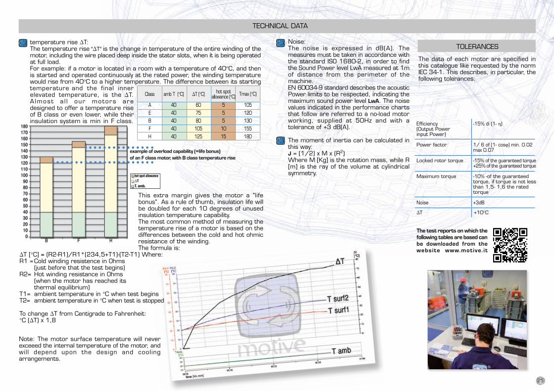
Noise:The noise is expressed in dB(A). Themeasures must be taken in accordance withthe standard ISO 1680-2, in order to findthe Sound Power level LwA measured at 1mof distance from the perimeter of themachine.EN 60034-9 standard describes the acousticPower limits to be respected, indicating themaximum sound power level LwA. The noisevalues indicated in the performance chartsthat follow are referred to a no-load motorworking, supplied at 50Hz and with atolerance of +3 dB(A).
The moment of inertia can be calculated inthis way:J = (1/2) x M x (R2)Where M [Kg] is the rotation mass, while R[m] is the ray of the volume at cylindricalsymmetry.
TOLERANCES
Efficiency -15% di (1- η)(Output Powerinput Power)
Power factor 1/ 6 of (1- cosϕ) min. 0.02max 0.07
Locked rotor torque -15% of the guaranteed torque+25% of the guaranteed torque
Maximum torque -10% -of the guaranteed torque, if torque is not lessthan 1,5- 1,6 the rated torque
Noise +3dB
∆T +10°C
The data of each motor are specified inthis catalogue like requested by the normIEC 34-1. This describes, in particular, thefollowing tolerances:
example of overload capability (=life bonus)of an F class motor, with B class temperature rise
temperature rise ∆T:The temperature rise "∆T" is the change in temperature of the entire winding of themotor, including the wire placed deep inside the stator slots, when it is being operatedat full load.For example: if a motor is located in a room with a temperature of 40°C, and thenis started and operated continuously at the rated power, the winding temperaturewould rise from 40°C to a higher temperature. The difference between its startingtemperature and the final innerelevated temperature, is the ∆T.A lmost a l l our motors aredesigned to offer a temperature riseof B class or even lower, while theirinsulation system is min in F class.
This extra margin gives the motor a "lifebonus". As a rule of thumb, insulation life willbe doubled for each 10 degrees of unusedinsulation temperature capability.The most common method of measuring thetemperature rise of a motor is based on thedifferences between the cold and hot ohmicresistance of the winding.The formula is:
∆T [°C] = (R2-R1)/R1*(234,5+T1)-(T2-T1) Where:R1 =Cold winding resistence in Ohms
(just before that the test begins)R2= Hot winding resistance in Ohms
(when the motor has reached itsthermal equilibrium)
T1= ambient temperature in °C when test beginsT2= ambient temperature in °C when test is stopped
To change ∆T from Centigrade to Fahrenheit:°C (∆T) x 1,8
Note: The motor surface temperature will neverexceeed the internal temperature of the motor, andwil l depend upon the design and coolingarrangements.
Class amb T (°C) ∆T (°C) hot spotallowance (°C) Tmax (°C)
A 40 60 5 105E 40 75 5 120B 40 80 5 130F 40 105 10 155H 40 125 15 180
The test reports on which thefollowing tables are based canbe downloaded from thewebsite www.motive. it
TECHNICAL DATA
hot spot allowanceΔTT. amb.
25
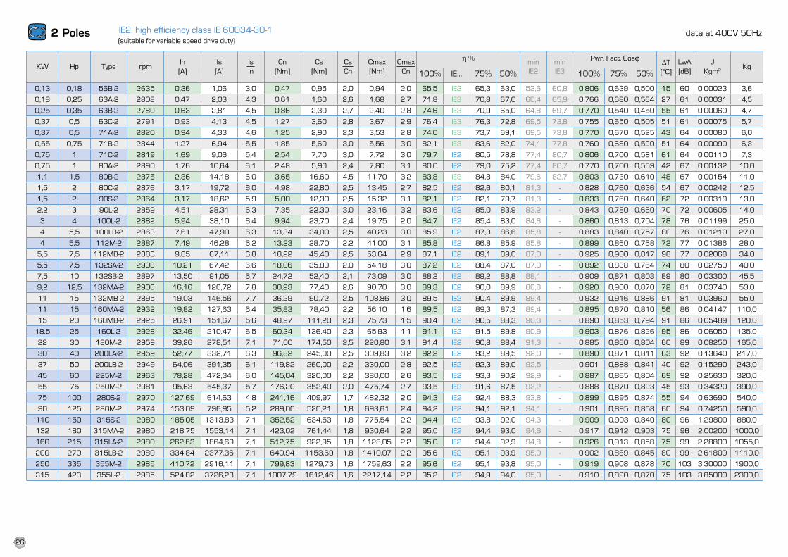
0,13 0,18 56B-2 2635 0,36 1,06 3,0 0,47 0,95 2,0 0,94 2,0 65,5 IE3 65,3 63,0 53,6 60,8 0,806 0,639 0,500 15 60 0,00023 3,6
0,18 0,25 63A-2 2808 0,47 2,03 4,3 0,61 1,60 2,6 1,68 2,7 71,8 IE3 70,8 67,0 60,4 65,9 0,766 0,680 0,564 27 61 0,00031 4,5
0,25 0,35 63B-2 2780 0,63 2,81 4,5 0,86 2,30 2,7 2,40 2,8 74,6 IE3 70,9 65,0 64,8 69,7 0,770 0,540 0,450 55 61 0,00060 4,7
0,37 0,5 63C-2 2791 0,93 4,13 4,5 1,27 3,60 2,8 3,67 2,9 76,4 IE3 76,3 72,8 69,5 73,8 0,755 0,650 0,505 51 61 0,00075 5,7
0,37 0,5 71A-2 2820 0,94 4,33 4,6 1,25 2,90 2,3 3,53 2,8 74,0 IE3 73,7 69,1 69,5 73,8 0,770 0,670 0,525 43 64 0,00080 6,0
0,55 0,75 71B-2 2844 1,27 6,94 5,5 1,85 5,60 3,0 5,56 3,0 82,1 IE3 83,6 82,0 74,1 77,8 0,760 0,680 0,520 51 64 0,00090 6,3
0,75 1 71C-2 2819 1,69 9,06 5,4 2,54 7,70 3,0 7,72 3,0 79,7 IE2 80,5 78,8 77,4 80,7 0,806 0,700 0,581 61 64 0,00110 7,3
0,75 1 80A-2 2890 1,76 10,64 6,1 2,48 5,90 2,4 7,80 3,1 80,0 IE2 79,0 75,2 77,4 80,7 0,770 0,700 0,559 42 67 0,00132 10,0
1,1 1,5 80B-2 2875 2,36 14,18 6,0 3,65 16,60 4,5 11,70 3,2 83,8 IE3 84,8 84,0 79,6 82,7 0,803 0,730 0,610 48 67 0,00154 11,0
1,5 2 80C-2 2876 3,17 19,72 6,0 4,98 22,80 2,5 13,45 2,7 82,5 IE2 82,6 80,1 81,3 - 0,828 0,760 0,636 54 67 0,00242 12,5
1,5 2 90S-2 2864 3,17 18,62 5,9 5,00 12,30 2,5 15,32 3,1 82,1 IE2 82,1 79,7 81,3 - 0,833 0,760 0,640 62 72 0,00319 13,0
2,2 3 90l-2 2859 4,51 28,31 6,3 7,35 22,30 3,0 23,16 3,2 83,6 IE2 85,0 83,9 83,2 - 0,843 0,780 0,660 70 72 0,00605 14,0
3 4 100l-2 2882 5,94 38,10 6,4 9,94 23,70 2,4 19,75 2,0 84,7 IE2 85,4 83,0 84,6 - 0,860 0,813 0,704 78 76 0,01199 25,0
4 5,5 100lB-2 2863 7,61 47,90 6,3 13,34 34,00 2,5 40,23 3,0 85,9 IE2 87,3 86,6 85,8 - 0,883 0,840 0,757 80 76 0,01210 27,0
4 5,5 112M-2 2887 7,49 46,28 6,2 13,23 28,70 2,2 41,00 3,1 85,8 IE2 86,8 85,9 85,8 - 0,899 0,860 0,768 72 77 0,01386 28,0
5,5 7,5 112MB-2 2883 9,85 67,11 6,8 18,22 45,40 2,5 53,64 2,9 87,1 IE2 89,1 89,0 87,0 - 0,925 0,900 0,817 98 77 0,02068 34,0
5,5 7,5 132SA-2 2908 10,21 67,42 6,6 18,06 35,80 2,0 54,18 3,0 87,2 IE2 88,4 87,0 87,0 - 0,892 0,838 0,764 74 80 0,02750 40,0
7,5 10 132SB-2 2897 13,50 91,05 6,7 24,72 52,40 2,1 73,09 3,0 88,2 IE2 89,2 88,8 88,1 - 0,909 0,871 0,803 89 80 0,03300 45,5
9,2 12,5 132MA-2 2906 16,16 126,72 7,8 30,23 77,40 2,6 90,70 3,0 89,3 IE2 90,0 89,9 88,8 - 0,920 0,900 0,870 72 81 0,03740 53,0
11 15 132MB-2 2895 19,03 146,56 7,7 36,29 90,72 2,5 108,86 3,0 89,5 IE2 90,4 89,9 89,4 - 0,932 0,916 0,886 91 81 0,03960 55,0
11 15 160MA-2 2932 19,82 127,63 6,4 35,83 78,40 2,2 56,10 1,6 89,5 IE2 89,3 87,3 89,4 - 0,895 0,870 0,810 56 86 0,04147 110,0
15 20 160MB-2 2925 26,91 151,67 5,6 48,97 111,20 2,3 75,73 1,5 90,4 IE2 90,5 88,3 90,3 - 0,890 0,853 0,794 91 86 0,05489 120,0
18,5 25 160l-2 2928 32,46 210,47 6,5 60,34 136,40 2,3 65,93 1,1 91,1 IE2 91,5 89,8 90,9 - 0,903 0,876 0,826 95 86 0,06050 135,0
22 30 180M-2 2959 39,26 278,51 7,1 71,00 174,50 2,5 220,80 3,1 91,4 IE2 90,8 88,4 91,3 - 0,885 0,860 0,804 60 89 0,08250 165,0
30 40 200lA-2 2959 52,77 332,71 6,3 96,82 245,00 2,5 309,83 3,2 92,2 IE2 93,2 89,5 92,0 - 0,890 0,871 0,811 63 92 0,13640 217,0
37 50 200lB-2 2949 64,06 391,35 6,1 119,82 260,00 2,2 330,00 2,8 92,5 IE2 92,3 89,0 92,5 - 0,901 0,888 0,841 40 92 0,15290 243,0
45 60 225M-2 2963 78,28 472,34 6,0 145,04 320,00 2,2 380,00 2,6 93,5 IE2 93,3 90,2 92,9 - 0,887 0,865 0,804 69 92 0,25630 320,0
55 75 250M-2 2981 95,63 545,37 5,7 176,20 352,40 2,0 475,74 2,7 93,5 IE2 91,6 87,5 93,2 - 0,888 0,870 0,823 45 93 0,34320 390,0
75 100 280S-2 2970 127,69 614,63 4,8 241,16 409,97 1,7 482,32 2,0 94,3 IE2 92,4 88,3 93,8 - 0,899 0,895 0,874 55 94 0,63690 540,0
90 125 280M-2 2974 153,09 796,95 5,2 289,00 520,21 1,8 693,61 2,4 94,2 IE2 94,1 92,1 94,1 - 0,901 0,895 0,858 60 94 0,74250 590,0
110 150 315S-2 2980 185,05 1313,83 7,1 352,52 634,53 1,8 775,54 2,2 94,4 IE2 93,8 92,0 94,3 - 0,909 0,903 0,840 80 96 1,29800 880,0
132 180 315MA-2 2980 218,75 1553,14 7,1 423,02 761,44 1,8 930,64 2,2 95,0 IE2 94,4 93,0 94,6 - 0,917 0,912 0,903 75 96 2,00200 1000,0
160 215 315lA-2 2980 262,63 1864,69 7,1 512,75 922,95 1,8 1128,05 2,2 95,0 IE2 94,4 92,9 94,8 - 0,926 0,913 0,858 75 99 2,28800 1055,0
200 270 315lB-2 2980 334,84 2377,36 7,1 640,94 1153,69 1,8 1410,07 2,2 95,6 IE2 95,1 93,9 95,0 - 0,902 0,889 0,845 80 99 2,61800 1110,0
250 335 355M-2 2985 410,72 2916,11 7,1 799,83 1279,73 1,6 1759,63 2,2 95,6 IE2 95,1 93,8 95,0 - 0,919 0,908 0,878 70 103 3,30000 1900,0
315 423 355l-2 2985 524,82 3726,23 7,1 1007,79 1612,46 1,6 2217,14 2,2 95,2 IE2 94,9 94,0 95,0 - 0,910 0,890 0,870 75 103 3,85000 2300,0
IE2, high efficiency class IE 60034-30-12 Poles asynchronous speed 3000 rpm
KW HP Type rpmIs----In
Cn(Nm)
Cs----Cn
In(A)
KgIs(A)
Cs(Nm)
Cmax(Nm)
Pwr. Fact.cosϕ
100% 75% 50%
LwA
(dB)
∆T
(°C)
J
Kgm2
Cmax----Cn
η %
100% 75% 50%
min
IE2
data at 400V 50Hz(suitable for variable speed drive duty)
KW Hp Type rpmIn[A]
Is[A]
IsIn
Cn[Nm]
Cs[Nm]
CsCn
Cmax[Nm]
CmaxCn
h % minIE2
minIE3
Pwr. Fact. Cosj DT[°C]
lwA[dB]
JKgm2 Kg
100% IE… 75% 50% 100% 75% 50%
26
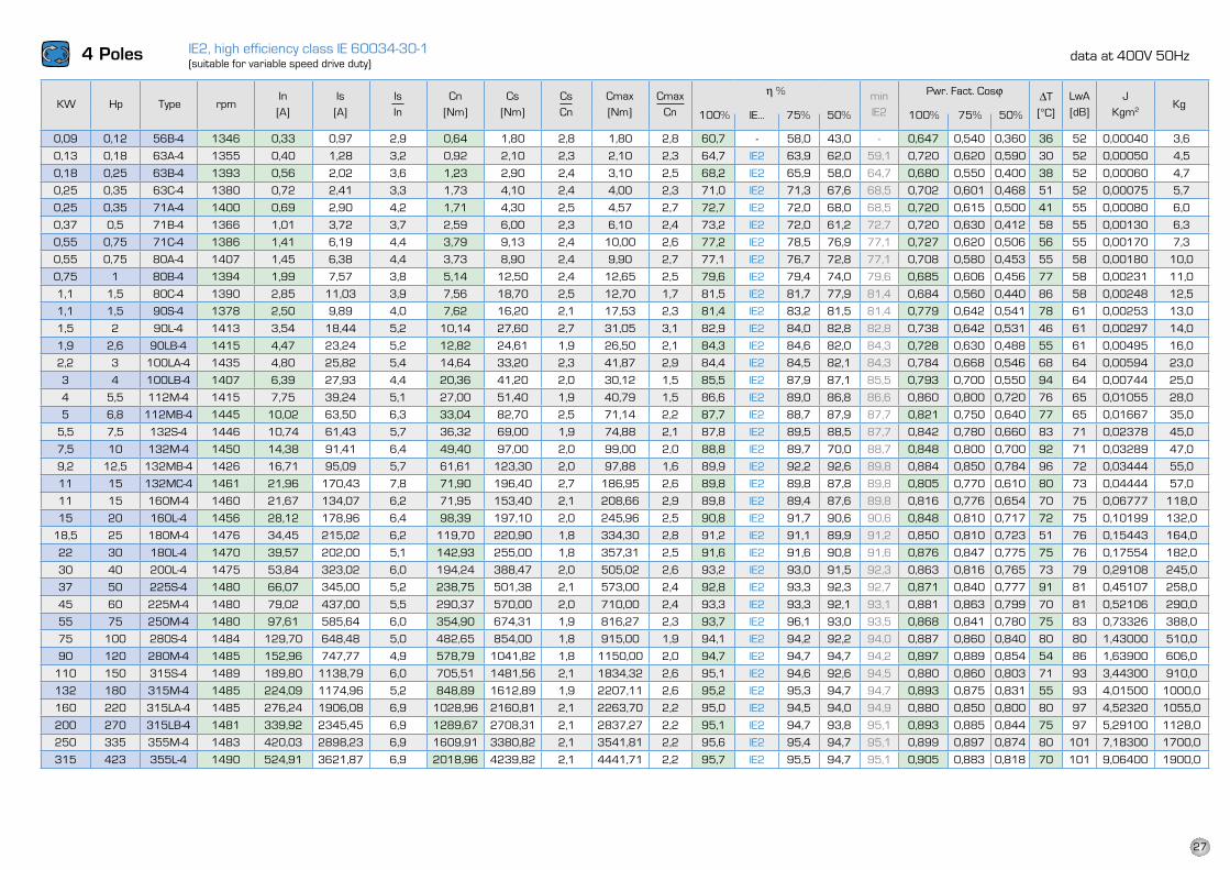
0,09 0,12 56B-4 1346 0,33 0,97 2,9 0,64 1,80 2,8 1,80 2,8 60,7 - 58,0 43,0 - 0,647 0,540 0,360 36 52 0,00040 3,6
0,13 0,18 63A-4 1355 0,40 1,28 3,2 0,92 2,10 2,3 2,10 2,3 64,7 IE2 63,9 62,0 59,1 0,720 0,620 0,590 30 52 0,00050 4,5
0,18 0,25 63B-4 1393 0,56 2,02 3,6 1,23 2,90 2,4 3,10 2,5 68,2 IE2 65,9 58,0 64,7 0,680 0,550 0,400 38 52 0,00060 4,7
0,25 0,35 63C-4 1380 0,72 2,41 3,3 1,73 4,10 2,4 4,00 2,3 71,0 IE2 71,3 67,6 68,5 0,702 0,601 0,468 51 52 0,00075 5,7
0,25 0,35 71A-4 1400 0,69 2,90 4,2 1,71 4,30 2,5 4,57 2,7 72,7 IE2 72,0 68,0 68,5 0,720 0,615 0,500 41 55 0,00080 6,0
0,37 0,5 71B-4 1366 1,01 3,72 3,7 2,59 6,00 2,3 6,10 2,4 73,2 IE2 72,0 61,2 72,7 0,720 0,630 0,412 58 55 0,00130 6,3
0,55 0,75 71C-4 1386 1,41 6,19 4,4 3,79 9,13 2,4 10,00 2,6 77,2 IE2 78,5 76,9 77,1 0,727 0,620 0,506 56 55 0,00170 7,3
0,55 0,75 80A-4 1407 1,45 6,38 4,4 3,73 8,90 2,4 9,90 2,7 77,1 IE2 76,7 72,8 77,1 0,708 0,580 0,453 55 58 0,00180 10,0
0,75 1 80B-4 1394 1,99 7,57 3,8 5,14 12,50 2,4 12,65 2,5 79,6 IE2 79,4 74,0 79,6 0,685 0,606 0,456 77 58 0,00231 11,0
1,1 1,5 80C-4 1390 2,85 11,03 3,9 7,56 18,70 2,5 12,70 1,7 81,5 IE2 81,7 77,9 81,4 0,684 0,560 0,440 86 58 0,00248 12,5
1,1 1,5 90S-4 1378 2,50 9,89 4,0 7,62 16,20 2,1 17,53 2,3 81,4 IE2 83,2 81,5 81,4 0,779 0,642 0,541 78 61 0,00253 13,0
1,5 2 90l-4 1413 3,54 18,44 5,2 10,14 27,60 2,7 31,05 3,1 82,9 IE2 84,0 82,8 82,8 0,738 0,642 0,531 46 61 0,00297 14,0
1,9 2,6 90lB-4 1415 4,47 23,24 5,2 12,82 24,61 1,9 26,50 2,1 84,3 IE2 84,6 82,0 84,3 0,728 0,630 0,488 55 61 0,00495 16,0
2,2 3 100lA-4 1435 4,80 25,82 5,4 14,64 33,20 2,3 41,87 2,9 84,4 IE2 84,5 82,1 84,3 0,784 0,668 0,546 68 64 0,00594 23,0
3 4 100lB-4 1407 6,39 27,93 4,4 20,36 41,20 2,0 30,12 1,5 85,5 IE2 87,9 87,1 85,5 0,793 0,700 0,550 94 64 0,00744 25,0
4 5,5 112M-4 1415 7,75 39,24 5,1 27,00 51,40 1,9 40,79 1,5 86,6 IE2 89,0 86,8 86,6 0,860 0,800 0,720 76 65 0,01055 28,0
5 6,8 112MB-4 1445 10,02 63,50 6,3 33,04 82,70 2,5 71,14 2,2 87,7 IE2 88,7 87,9 87,7 0,821 0,750 0,640 77 65 0,01667 35,0
5,5 7,5 132S-4 1446 10,74 61,43 5,7 36,32 69,00 1,9 74,88 2,1 87,8 IE2 89,5 88,5 87,7 0,842 0,780 0,660 83 71 0,02378 45,0
7,5 10 132M-4 1450 14,38 91,41 6,4 49,40 97,00 2,0 99,00 2,0 88,8 IE2 89,7 70,0 88,7 0,848 0,800 0,700 92 71 0,03289 47,0
9,2 12,5 132MB-4 1426 16,71 95,09 5,7 61,61 123,30 2,0 97,88 1,6 89,9 IE2 92,2 92,6 89,8 0,884 0,850 0,784 96 72 0,03444 55,0
11 15 132MC-4 1461 21,96 170,43 7,8 71,90 196,40 2,7 186,95 2,6 89,8 IE2 89,8 87,8 89,8 0,805 0,770 0,610 80 73 0,04444 57,0
11 15 160M-4 1460 21,67 134,07 6,2 71,95 153,40 2,1 208,66 2,9 89,8 IE2 89,4 87,6 89,8 0,816 0,776 0,654 70 75 0,06777 118,0
15 20 160l-4 1456 28,12 178,96 6,4 98,39 197,10 2,0 245,96 2,5 90,8 IE2 91,7 90,6 90,6 0,848 0,810 0,717 72 75 0,10199 132,0
18,5 25 180M-4 1476 34,45 215,02 6,2 119,70 220,90 1,8 334,30 2,8 91,2 IE2 91,1 89,9 91,2 0,850 0,810 0,723 51 76 0,15443 164,0
22 30 180l-4 1470 39,57 202,00 5,1 142,93 255,00 1,8 357,31 2,5 91,6 IE2 91,6 90,8 91,6 0,876 0,847 0,775 75 76 0,17554 182,0
30 40 200l-4 1475 53,84 323,02 6,0 194,24 388,47 2,0 505,02 2,6 93,2 IE2 93,0 91,5 92,3 0,863 0,816 0,765 73 79 0,29108 245,0
37 50 225S-4 1480 66,07 345,00 5,2 238,75 501,38 2,1 573,00 2,4 92,8 IE2 93,3 92,3 92,7 0,871 0,840 0,777 91 81 0,45107 258,0
45 60 225M-4 1480 79,02 437,00 5,5 290,37 570,00 2,0 710,00 2,4 93,3 IE2 93,3 92,1 93,1 0,881 0,863 0,799 70 81 0,52106 290,0
55 75 250M-4 1480 97,61 585,64 6,0 354,90 674,31 1,9 816,27 2,3 93,7 IE2 96,1 93,0 93,5 0,868 0,841 0,780 75 83 0,73326 388,0
75 100 280S-4 1484 129,70 648,48 5,0 482,65 854,00 1,8 915,00 1,9 94,1 IE2 94,2 92,2 94,0 0,887 0,860 0,840 80 80 1,43000 510,0
90 120 280M-4 1485 152,96 747,77 4,9 578,79 1041,82 1,8 1150,00 2,0 94,7 IE2 94,7 94,7 94,2 0,897 0,889 0,854 54 86 1,63900 606,0
110 150 315S-4 1489 189,80 1138,79 6,0 705,51 1481,56 2,1 1834,32 2,6 95,1 IE2 94,6 92,6 94,5 0,880 0,860 0,803 71 93 3,44300 910,0
132 180 315M-4 1485 224,09 1174,96 5,2 848,89 1612,89 1,9 2207,11 2,6 95,2 IE2 95,3 94,7 94,7 0,893 0,875 0,831 55 93 4,01500 1000,0
160 220 315lA-4 1485 276,24 1906,08 6,9 1028,96 2160,81 2,1 2263,70 2,2 95,0 IE2 94,5 94,0 94,9 0,880 0,850 0,800 80 97 4,52320 1055,0
200 270 315lB-4 1481 339,92 2345,45 6,9 1289,67 2708,31 2,1 2837,27 2,2 95,1 IE2 94,7 93,8 95,1 0,893 0,885 0,844 75 97 5,29100 1128,0
250 335 355M-4 1483 420,03 2898,23 6,9 1609,91 3380,82 2,1 3541,81 2,2 95,6 IE2 95,4 94,7 95,1 0,899 0,897 0,874 80 101 7,18300 1700,0
315 423 355l-4 1490 524,91 3621,87 6,9 2018,96 4239,82 2,1 4441,71 2,2 95,7 IE2 95,5 94,7 95,1 0,905 0,883 0,818 70 101 9,06400 1900,0
IE2, high efficiency class IE 60034-30-14 Poles asynchronous speed 1500 rpm
KW HP Type rpmIs----In
Cn(Nm)
Cs----Cn
In(A)
KgIs(A)
Cs(Nm)
Cmax(Nm)
LwA
(dB)
J
Kgm2
∆T
(°C)
Pwr. Fact. cosϕ
100% 75% 50%
Cmax----Cn
η %
100% 75% 50%
min
IE2
data at 400V 50Hz(suitable for variable speed drive duty)
KW Hp Type rpmIn[A]
Is[A]
IsIn
Cn[Nm]
Cs[Nm]
CsCn
Cmax[Nm]
CmaxCn
h % minIE2
Pwr. Fact. Cosj DT[°C]
lwA[dB]
JKgm2
Kg100% IE… 75% 50% 100% 75% 50%
27
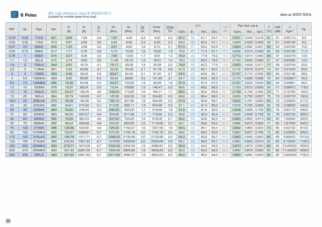
IE2, high efficiency class IE 60034-30-1
0,18 0,25 71A-6 921 0,66 1,93 2,9 1,87 4,20 2,3 4,30 2,3 62,7 IE2 61,1 53,7 56,6 0,631 0,540 0,418 41 51 0,00110 6,0
0,25 0,35 71B-6 910 0,87 2,62 3,0 2,62 6,00 2,3 6,00 2,3 64,0 IE2 62,5 57,1 61,6 0,650 0,550 0,426 54 51 0,00140 6,3
0,37 0,5 80A-6 928 1,20 3,58 3,0 3,81 6,80 1,8 8,10 2,1 67,3 IE1 66,0 60,9 67,6 0,660 0,562 0,451 58 53 0,00160 10,0
0,55 0,75 80B-6 917 1,71 4,72 2,8 5,73 10,40 1,8 10,60 1,9 70,5 IE1 71,4 67,7 73,1 0,658 0,574 0,440 80 53 0,00190 11,0
0,75 1 90S-6 915 2,01 5,98 3,0 7,83 13,00 1,7 9,97 1,3 76,0 IE2 77,9 75,2 75,9 0,710 0,610 0,480 69 57 0,00319 13,0
1,1 1,5 90l-6 915 2,74 9,93 3,6 11,48 22,10 1,9 16,57 1,4 78,3 IE2 80,2 79,3 78,1 0,740 0,650 0,560 67 57 0,00385 14,0
1,5 2 100l-6 944 3,91 16,15 4,1 15,17 29,39 1,9 35,09 2,3 79,9 IE2 80,3 77,6 79,8 0,693 0,609 0,477 71 58 0,00759 23,0
2,2 3 112M-6 951 5,45 25,84 4,7 22,09 45,40 2,1 57,79 2,6 81,9 IE2 82,7 80,4 81,8 0,712 0,610 0,475 74 61 0,01540 25,0
3 4 132S-6 969 6,95 38,23 5,5 29,57 62,40 2,1 81,20 2,7 84,5 IE2 84,6 82,1 83,3 0,737 0,710 0,536 63 64 0,03146 28,0
4 5,5 132MA-6 969 8,85 56,55 6,4 39,42 89,90 2,3 121,80 3,1 84,7 IE2 84,5 82,0 84,6 0,770 0,690 0,566 76 64 0,03927 45,0
5,5 7,5 132MB-6 966 12,38 65,09 5,3 54,37 103,20 1,9 95,28 1,8 87,0 IE2 87,5 87,0 86,0 0,737 0,653 0,545 64 64 0,04961 55,0
7,5 10 160M-6 978 16,97 88,24 5,2 73,24 109,85 1,5 146,47 2,0 88,6 IE2 89,2 88,5 87,2 0,720 0,670 0,600 50 71 0,08910 118,0
11 15 160l-6 970 23,37 106,35 4,6 108,30 173,28 1,6 184,11 1,7 89,5 IE2 90,5 89,9 88,7 0,759 0,700 0,582 70 71 0,12760 125,0
15 20 180l-6 984 29,79 140,65 4,7 145,58 232,93 1,6 334,83 2,3 89,8 IE2 89,4 88,0 89,7 0,809 0,750 0,657 75 73 0,22770 160,0
18,5 25 200lA-6 970 35,28 183,46 5,2 182,14 327,85 1,8 454,99 2,5 91,0 IE2 90,8 89,7 90,4 0,832 0,781 0,685 60 76 0,34650 217,0
22 30 200lB-6 982 42,61 215,40 5,1 213,95 385,11 1,8 534,88 2,5 91,1 IE2 91,0 89,3 90,9 0,818 0,763 0,668 80 76 0,39600 244,0
30 40 225M-6 980 55,62 236,55 4,3 292,35 503,00 1,7 518,00 1,8 91,8 IE2 91,6 92,0 91,7 0,848 0,828 0,759 60 76 0,60170 295,0
37 50 250M-6 983 68,00 297,27 4,4 359,46 611,08 1,7 718,92 2,0 92,6 IE2 92,3 92,4 92,2 0,848 0,828 0,759 56 78 0,92730 365,0
45 60 280S-6 982 78,93 360,33 4,6 437,63 700,20 1,6 919,02 2,1 93,2 IE2 93,6 92,2 92,7 0,883 0,865 0,813 42 80 1,52900 500,0
55 75 280M-6 985 96,24 459,99 4,8 533,25 853,20 1,6 1119,82 2,1 93,1 IE2 93,6 93,2 93,1 0,886 0,873 0,822 71 80 1,81500 545,0
75 100 315S-6 986 132,96 534,60 4,0 726,42 1162,27 1,6 1307,56 1,8 94,5 IE2 95,1 94,4 93,7 0,862 0,860 0,820 70 85 4,52100 810,0
90 125 315MA-6 985 159,67 1069,81 6,7 872,59 1745,18 2,0 1745,18 2,0 94,6 IE2 94,5 93,6 94,0 0,860 0,831 0,766 75 85 5,25800 900,0
110 150 315lA-6 985 195,78 1311,71 6,7 1066,50 2132,99 2,0 2132,99 2,0 94,3 IE2 93,9 93,7 94,3 0,860 0,840 0,820 80 85 5,99500 1010,0
132 180 315lB-6 985 233,94 1567,40 6,7 1279,80 2559,59 2,0 2559,59 2,0 94,7 IE2 94,2 93,7 94,6 0,860 0,840 0,810 80 85 6,73200 1140,0
160 220 355MA-6 990 279,71 1874,08 6,7 1543,43 2932,53 1,9 3086,87 2,0 94,9 IE2 94,2 93,3 94,8 0,870 0,870 0,850 80 92 10,45000 1550,0
200 270 355MB-6 990 341,43 2287,55 6,7 1929,29 3665,66 1,9 3858,59 2,0 95,0 IE2 94,5 94,0 95,0 0,890 0,870 0,850 80 92 11,44000 1600,0
250 335 355l-6 990 431,63 2891,93 6,7 2411,62 4582,07 1,9 4823,23 2,0 95,0 IE2 95,0 94,0 95,0 0,880 0,860 0,840 80 92 13,64000 1700,0
6 Poles asynchronous speed 1000 rpm
KW HP Type rpmIs----In
Cn(Nm)
Cs----Cn
In(A)
J
Kgm2 KgIs(A)
Cs(Nm)
Cmax(Nm)
LwA
(dB)
∆T
(°C)
Pwr. fact. cosϕ
100% 75% 50%
Cmax----Cn
η %
100% 75% 50%
min
IE2
data at 400V 50Hz(suitable for variable speed drive duty)
KW Hp Type rpmIn[A]
Is[A]
IsIn
Cn[Nm]
Cs[Nm]
CsCn
Cmax[Nm]
CmaxCn
h % minIE2
Pwr. fact. cos j T[°C]
lwA[dB]
JKgm2
Kg100% IE… 75% 50% 100% 75% 50%
28
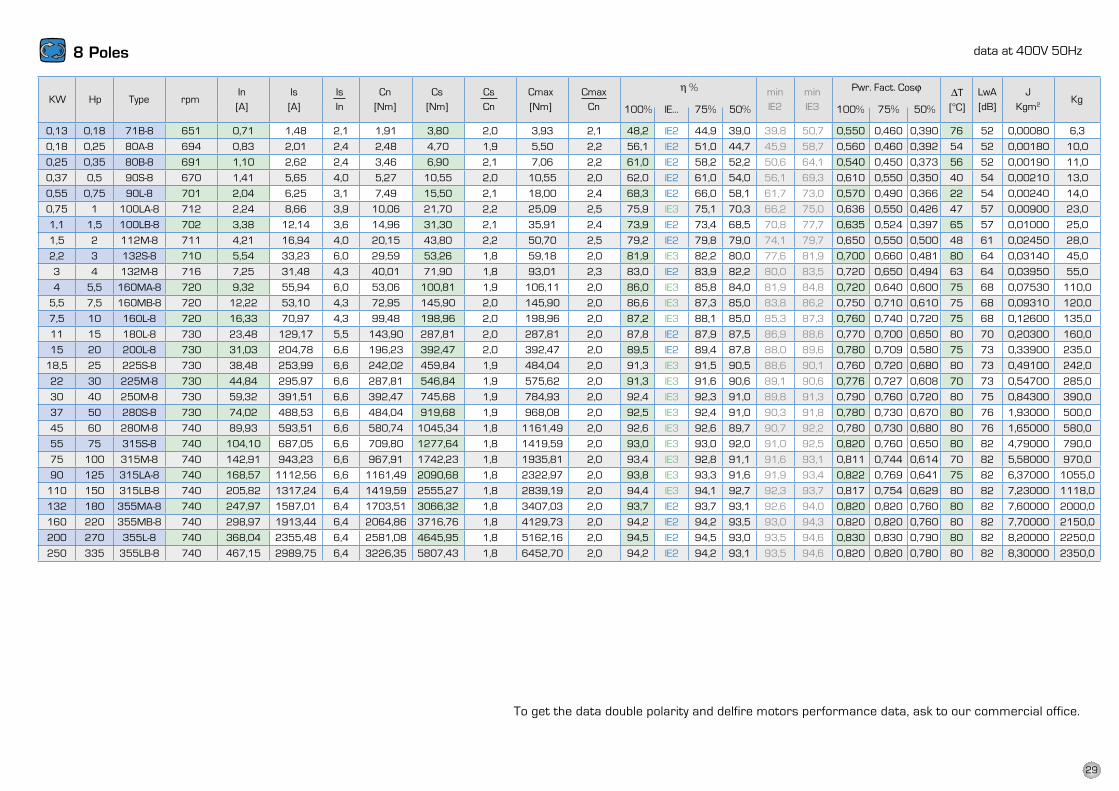
0,13 0,18 71B-8 651 0,71 1,48 2,1 1,91 3,80 2,0 3,93 2,1 48,2 IE2 44,9 39,0 39,8 50,7 0,550 0,460 0,390 76 52 0,00080 6,3
0,18 0,25 80A-8 694 0,83 2,01 2,4 2,48 4,70 1,9 5,50 2,2 56,1 IE2 51,0 44,7 45,9 58,7 0,560 0,460 0,392 54 52 0,00180 10,0
0,25 0,35 80B-8 691 1,10 2,62 2,4 3,46 6,90 2,1 7,06 2,2 61,0 IE2 58,2 52,2 50,6 64,1 0,540 0,450 0,373 56 52 0,00190 11,0
0,37 0,5 90S-8 670 1,41 5,65 4,0 5,27 10,55 2,0 10,55 2,0 62,0 IE2 61,0 54,0 56,1 69,3 0,610 0,550 0,350 40 54 0,00210 13,0
0,55 0,75 90l-8 701 2,04 6,25 3,1 7,49 15,50 2,1 18,00 2,4 68,3 IE2 66,0 58,1 61,7 73,0 0,570 0,490 0,366 22 54 0,00240 14,0
0,75 1 100lA-8 712 2,24 8,66 3,9 10,06 21,70 2,2 25,09 2,5 75,9 IE3 75,1 70,3 66,2 75,0 0,636 0,550 0,426 47 57 0,00900 23,0
1,1 1,5 100lB-8 702 3,38 12,14 3,6 14,96 31,30 2,1 35,91 2,4 73,9 IE2 73,4 68,5 70,8 77,7 0,635 0,524 0,397 65 57 0,01000 25,0
1,5 2 112M-8 711 4,21 16,94 4,0 20,15 43,80 2,2 50,70 2,5 79,2 IE2 79,8 79,0 74,1 79,7 0,650 0,550 0,500 48 61 0,02450 28,0
2,2 3 132S-8 710 5,54 33,23 6,0 29,59 53,26 1,8 59,18 2,0 81,9 IE3 82,2 80,0 77,6 81,9 0,700 0,660 0,481 80 64 0,03140 45,0
3 4 132M-8 716 7,25 31,48 4,3 40,01 71,90 1,8 93,01 2,3 83,0 IE2 83,9 82,2 80,0 83,5 0,720 0,650 0,494 63 64 0,03950 55,0
4 5,5 160MA-8 720 9,32 55,94 6,0 53,06 100,81 1,9 106,11 2,0 86,0 IE3 85,8 84,0 81,9 84,8 0,720 0,640 0,600 75 68 0,07530 110,0
5,5 7,5 160MB-8 720 12,22 53,10 4,3 72,95 145,90 2,0 145,90 2,0 86,6 IE3 87,3 85,0 83,8 86,2 0,750 0,710 0,610 75 68 0,09310 120,0
7,5 10 160l-8 720 16,33 70,97 4,3 99,48 198,96 2,0 198,96 2,0 87,2 IE3 88,1 85,0 85,3 87,3 0,760 0,740 0,720 75 68 0,12600 135,0
11 15 180l-8 730 23,48 129,17 5,5 143,90 287,81 2,0 287,81 2,0 87,8 IE2 87,9 87,5 86,9 88,6 0,770 0,700 0,650 80 70 0,20300 160,0
15 20 200l-8 730 31,03 204,78 6,6 196,23 392,47 2,0 392,47 2,0 89,5 IE2 89,4 87,8 88,0 89,6 0,780 0,709 0,580 75 73 0,33900 235,0
18,5 25 225S-8 730 38,48 253,99 6,6 242,02 459,84 1,9 484,04 2,0 91,3 IE3 91,5 90,5 88,6 90,1 0,760 0,720 0,680 80 73 0,49100 242,0
22 30 225M-8 730 44,84 295,97 6,6 287,81 546,84 1,9 575,62 2,0 91,3 IE3 91,6 90,6 89,1 90,6 0,776 0,727 0,608 70 73 0,54700 285,0
30 40 250M-8 730 59,32 391,51 6,6 392,47 745,68 1,9 784,93 2,0 92,4 IE3 92,3 91,0 89,8 91,3 0,790 0,760 0,720 80 75 0,84300 390,0
37 50 280S-8 730 74,02 488,53 6,6 484,04 919,68 1,9 968,08 2,0 92,5 IE3 92,4 91,0 90,3 91,8 0,780 0,730 0,670 80 76 1,93000 500,0
45 60 280M-8 740 89,93 593,51 6,6 580,74 1045,34 1,8 1161,49 2,0 92,6 IE3 92,6 89,7 90,7 92,2 0,780 0,730 0,680 80 76 1,65000 580,0
55 75 315S-8 740 104,10 687,05 6,6 709,80 1277,64 1,8 1419,59 2,0 93,0 IE3 93,0 92,0 91,0 92,5 0,820 0,760 0,650 80 82 4,79000 790,0
75 100 315M-8 740 142,91 943,23 6,6 967,91 1742,23 1,8 1935,81 2,0 93,4 IE3 92,8 91,1 91,6 93,1 0,811 0,744 0,614 70 82 5,58000 970,0
90 125 315lA-8 740 168,57 1112,56 6,6 1161,49 2090,68 1,8 2322,97 2,0 93,8 IE3 93,3 91,6 91,9 93,4 0,822 0,769 0,641 75 82 6,37000 1055,0
110 150 315lB-8 740 205,82 1317,24 6,4 1419,59 2555,27 1,8 2839,19 2,0 94,4 IE3 94,1 92,7 92,3 93,7 0,817 0,754 0,629 80 82 7,23000 1118,0
132 180 355MA-8 740 247,97 1587,01 6,4 1703,51 3066,32 1,8 3407,03 2,0 93,7 IE2 93,7 93,1 92,6 94,0 0,820 0,820 0,760 80 82 7,60000 2000,0
160 220 355MB-8 740 298,97 1913,44 6,4 2064,86 3716,76 1,8 4129,73 2,0 94,2 IE2 94,2 93,5 93,0 94,3 0,820 0,820 0,760 80 82 7,70000 2150,0
200 270 355l-8 740 368,04 2355,48 6,4 2581,08 4645,95 1,8 5162,16 2,0 94,5 IE2 94,5 93,0 93,5 94,6 0,830 0,830 0,790 80 82 8,20000 2250,0
250 335 355lB-8 740 467,15 2989,75 6,4 3226,35 5807,43 1,8 6452,70 2,0 94,2 IE2 94,2 93,1 93,5 94,6 0,820 0,820 0,780 80 82 8,30000 2350,0
8 Poles asynchronous speed 750 rpm
KW HP Type rpmIs----In
Cn(Nm)
Cs----Cn
Cmax----Cn
In(A)
J
Kgm2 KgIs(A)
Cs(Nm)
Cmax(Nm)
To get the data double polarity motors, contact our export office.
LwA
(dB)
∆T
(°C)
Pwr. fact. cosϕ
100% 75% 50%
η %
100% 75% 50%
data at 400V 50Hz
KW Hp Type rpmIn[A]
Is[A]
IsIn
Cn[Nm]
Cs[Nm]
CsCn
Cmax[Nm]
CmaxCn
h % minIE2
minIE3
Pwr. Fact. Cosj DT[°C]
lwA[dB]
JKgm2
Kg100% IE… 75% 50% 100% 75% 50%
To get the data double polarity and delfire motors performance data, ask to our commercial office.
29
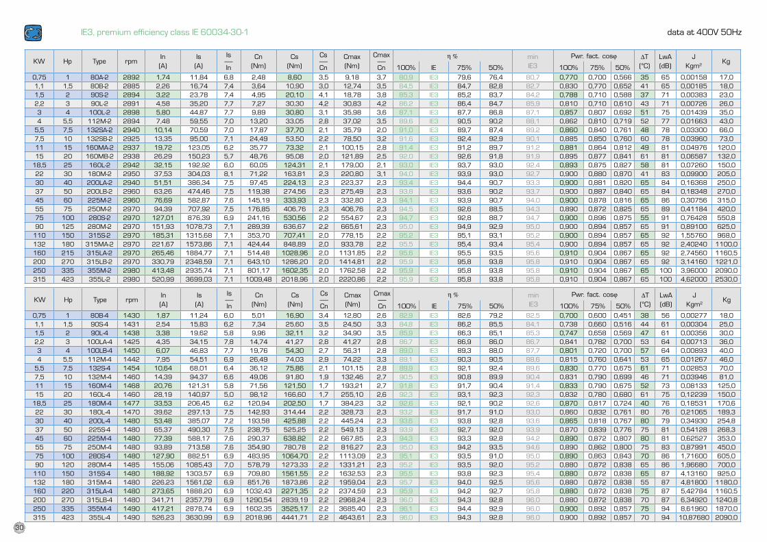
0,75 1 80A-2 2892 1,74 11,84 6,8 2,48 8,60 3,5 9,18 3,7 80,9 IE3 79,6 76,4 80,7 0,770 0,700 0,566 35 65 0,00158 17,01,1 1,5 80B-2 2885 2,26 16,74 7,4 3,64 10,90 3,0 12,74 3,5 84,5 IE3 84,7 82,8 82,7 0,830 0,770 0,652 41 65 0,00185 18,01,5 2 90S-2 2894 3,22 23,78 7,4 4,95 20,10 4,1 18,78 3,8 85,3 IE3 85,2 83,7 84,2 0,788 0,710 0,588 37 71 0,00383 23,02,2 3 90l-2 2891 4,58 35,20 7,7 7,27 30,30 4,2 30,83 4,2 86,2 IE3 86,4 84,7 85,9 0,810 0,710 0,610 43 71 0,00726 26,03 4 100l-2 2898 5,80 44,87 7,7 9,89 30,80 3,1 35,98 3,6 87,1 IE3 87,7 86,8 87,1 0,857 0,807 0,692 51 75 0,01439 35,04 5,5 112M-2 2894 7,48 59,55 7,0 13,20 33,05 2,8 37,02 3,5 89,6 IE3 90,5 90,2 88,1 0,862 0,810 0,719 52 77 0,01663 43,0
5,5 7,5 132SA-2 2940 10,14 70,59 7,0 17,87 37,70 2,1 35,79 2,0 91,0 IE3 89,7 87,4 89,2 0,860 0,840 0,761 48 78 0,03300 66,07,5 10 132SB-2 2925 13,35 95,00 7,1 24,49 53,50 2,2 78,50 3,2 91,6 IE3 92,4 92,9 90,1 0,885 0,850 0,760 60 78 0,03960 73,011 15 160MA-2 2937 19,72 123,05 6,2 35,77 73,32 2,1 100,15 2,8 91,4 IE3 91,2 89,7 91,2 0,881 0,864 0,812 49 81 0,04976 120,015 20 160MB-2 2938 26,29 150,23 5,7 48,76 95,08 2,0 121,89 2,5 92,0 IE3 92,6 91,8 91,9 0,895 0,877 0,841 61 81 0,06587 132,0
18,5 25 160l-2 2942 32,15 192,92 6,0 60,05 124,31 2,1 179,00 2,1 93,0 IE3 93,7 93,0 92,4 0,893 0,875 0,827 58 81 0,07260 150,022 30 180M-2 2950 37,53 304,03 8,1 71,22 163,81 2,3 220,80 3,1 94,0 IE3 93,9 93,0 92,7 0,900 0,880 0,870 41 83 0,09900 205,030 40 200lA-2 2940 51,51 386,34 7,5 97,45 224,13 2,3 223,37 2,3 93,4 IE3 94,4 90,7 93,3 0,900 0,881 0,820 65 84 0,16368 250,037 50 200lB-2 2960 63,26 474,46 7,5 119,38 274,56 2,3 275,49 2,3 93,8 IE3 93,6 90,2 93,7 0,900 0,887 0,840 65 84 0,18348 270,045 60 225M-2 2960 76,69 582,87 7,6 145,19 333,93 2,3 332,80 2,3 94,1 IE3 93,9 90,7 94,0 0,900 0,878 0,816 65 86 0,30756 315,055 75 250M-2 2970 94,39 707,92 7,5 176,85 406,76 2,3 406,76 2,3 94,5 IE3 92,6 88,5 94,3 0,890 0,872 0,825 65 89 0,41184 420,075 100 280S-2 2970 127,01 876,39 6,9 241,16 530,56 2,2 554,67 2,3 94,7 IE3 92,8 88,7 94,7 0,900 0,896 0,875 55 91 0,76428 550,890 125 280M-2 2970 151,93 1078,73 7,1 289,39 636,67 2,2 665,61 2,3 95,0 IE3 94,9 92,9 95,0 0,900 0,894 0,857 65 91 0,89100 625,0
110 150 315S-2 2970 185,31 1315,68 7,1 353,70 707,41 2,0 778,15 2,2 95,2 IE3 95,1 93,1 95,2 0,900 0,894 0,857 65 92 1,55760 968,0132 180 315MA-2 2970 221,67 1573,86 7,1 424,44 848,89 2,0 933,78 2,2 95,5 IE3 95,4 93,4 95,4 0,900 0,894 0,857 65 92 2,40240 1100,0160 215 315lA-2 2970 265,46 1884,77 7,1 514,48 1028,96 2,0 1131,85 2,2 95,6 IE3 95,5 93,5 95,6 0,910 0,904 0,867 65 92 2,74560 1160,5200 270 315lB-2 2970 330,79 2348,59 7,1 643,10 1286,20 2,0 1414,81 2,2 95,9 IE3 95,8 93,8 95,8 0,910 0,904 0,867 65 92 3,14160 1221,0250 335 355M-2 2980 413,48 2935,74 7,1 801,17 1602,35 2,0 1762,58 2,2 95,9 IE3 95,8 93,8 95,8 0,910 0,904 0,867 65 100 3,96000 2090,0315 423 355l-2 2980 520,99 3699,03 7,1 1009,48 2018,96 2,0 2220,86 2,2 95,9 IE3 95,8 93,8 95,8 0,910 0,904 0,867 65 100 4,62000 2530,0
0,75 1 80B-4 1430 1,87 11,24 6,0 5,01 16,90 3,4 12,80 2,6 82,9 IE3 82,6 79,2 82,5 0,700 0,600 0,451 38 56 0,00277 18,01,1 1,5 90S-4 1431 2,54 15,83 6,2 7,34 25,60 3,5 24,50 3,3 84,8 IE3 86,2 85,5 84,1 0,738 0,660 0,516 44 61 0,00304 25,01,5 2 90l-4 1438 3,38 19,62 5,8 9,96 32,11 3,2 34,90 3,5 85,9 IE3 86,3 85,1 85,3 0,747 0,658 0,569 47 61 0,00356 30,02,2 3 100lA-4 1425 4,35 34,15 7,8 14,74 41,27 2,8 41,27 2,8 86,7 IE3 86,9 86,0 86,7 0,841 0,782 0,700 53 64 0,00713 36,03 4 100lB-4 1450 6,07 46,83 7,7 19,76 54,30 2,7 56,31 2,8 89,0 IE3 89,3 88,0 87,7 0,801 0,720 0,700 57 64 0,00893 40,04 5,5 112M-4 1442 7,95 54,51 6,9 26,49 74,03 2,9 74,22 3,3 89,1 IE3 90,3 90,5 88,6 0,815 0,760 0,641 53 65 0,01267 46,0
5,5 7,5 132S-4 1454 10,64 68,01 6,4 36,12 75,86 2,1 101,15 2,8 89,9 IE3 92,1 92,4 89,6 0,830 0,770 0,675 61 71 0,02853 70,07,5 10 132M-4 1460 14,39 94,37 6,6 49,06 91,80 1,9 132,46 2,7 90,5 IE3 90,8 89,9 90,4 0,831 0,790 0,699 46 71 0,03946 81,011 15 160M-4 1468 20,76 121,31 5,8 71,56 121,50 1,7 193,21 2,7 91,8 IE3 91,7 90,4 91,4 0,833 0,790 0,675 52 73 0,08133 125,015 20 160l-4 1460 28,19 140,97 5,0 98,12 166,60 1,7 255,10 2,6 92,3 IE3 93,1 92,3 92,3 0,832 0,780 0,680 61 75 0,12239 150,0
18,5 25 180M-4 1477 33,53 206,45 6,2 120,94 202,50 1,7 384,23 3,2 92,6 IE3 92,1 90,2 92,6 0,870 0,817 0,724 40 76 0,18531 170,622 30 180l-4 1470 39,62 297,13 7,5 142,93 314,44 2,2 328,73 2,3 93,2 IE3 91,7 91,0 93,0 0,860 0,832 0,761 80 76 0,21065 189,330 40 200l-4 1480 53,48 385,07 7,2 193,58 425,88 2,2 445,24 2,3 93,6 IE3 93,8 92,8 93,6 0,865 0,818 0,767 80 79 0,34930 254,837 50 225S-4 1480 65,37 490,30 7,5 238,75 525,25 2,2 549,13 2,3 93,9 IE3 92,7 92,0 93,9 0,870 0,839 0,776 75 81 0,54128 268,345 60 225M-4 1480 77,39 588,17 7,6 290,37 638,82 2,2 667,85 2,3 94,3 IE3 93,3 92,8 94,2 0,890 0,872 0,807 80 81 0,62527 353,055 75 250M-4 1480 93,89 713,58 7,6 354,90 780,78 2,2 816,27 2,3 95,0 IE3 94,2 93,5 94,6 0,890 0,862 0,800 75 83 0,87991 450,075 100 280S-4 1480 127,90 882,51 6,9 483,95 1064,70 2,2 1113,09 2,3 95,1 IE3 93,5 91,0 95,0 0,890 0,863 0,843 70 86 1,71600 605,090 120 280M-4 1485 155,06 1085,43 7,0 578,79 1273,33 2,2 1331,21 2,3 95,2 IE3 93,5 92,0 95,2 0,880 0,872 0,838 65 86 1,96680 700,0
110 150 315S-4 1480 188,92 1303,57 6,9 709,80 1561,55 2,2 1632,53 2,3 95,5 IE3 93,8 92,3 95,4 0,880 0,872 0,838 65 87 4,13160 925,0132 180 315M-4 1480 226,23 1561,02 6,9 851,76 1873,86 2,2 1959,04 2,3 95,7 IE3 94,0 92,5 95,6 0,880 0,872 0,838 55 87 4,81800 1180,0160 220 315lA-4 1480 273,65 1888,20 6,9 1032,43 2271,35 2,2 2374,59 2,3 95,9 IE3 94,2 92,7 95,8 0,880 0,872 0,838 75 87 5,42784 1160,5200 270 315lB-4 1480 341,71 2357,79 6,9 1290,54 2839,19 2,2 2968,24 2,3 96,0 IE3 94,3 92,8 96,0 0,880 0,872 0,838 70 87 6,34920 1240,8250 335 355M-4 1490 417,21 2878,74 6,9 1602,35 3525,17 2,2 3685,40 2,3 96,1 IE3 94,4 92,9 96,0 0,900 0,892 0,857 75 94 8,61960 1870,0315 423 355l-4 1490 526,23 3630,99 6,9 2018,96 4441,71 2,2 4643,61 2,3 96,0 IE3 94,3 92,8 96,0 0,900 0,892 0,857 70 94 10,87680 2090,0
IE3, premium efficiency class IE 60034-30-1 data at 400V 50Hz
KW Hp Type rpmIn(A)
Is(A)
Is-----In
Cn(Nm)
Cs(Nm)
Cs-----Cn
Cmax(Nm)
Cmax-----Cn
h % minIE3
Pwr. fact. cosj DT(°C)
LwA(dB)
JKgm2
Kg100% IE 75% 50% 100% 75% 50%
KW Hp Type rpmIn(A)
Is(A)
Is-----In
Cn(Nm)
Cs(Nm)
Cs-----Cn
Cmax(Nm)
Cmax-----Cn
h % minIE3
Pwr. fact. cosj DT(°C)
LwA(dB)
JKgm2
Kg100% IE 75% 50% 100% 75% 50%
30
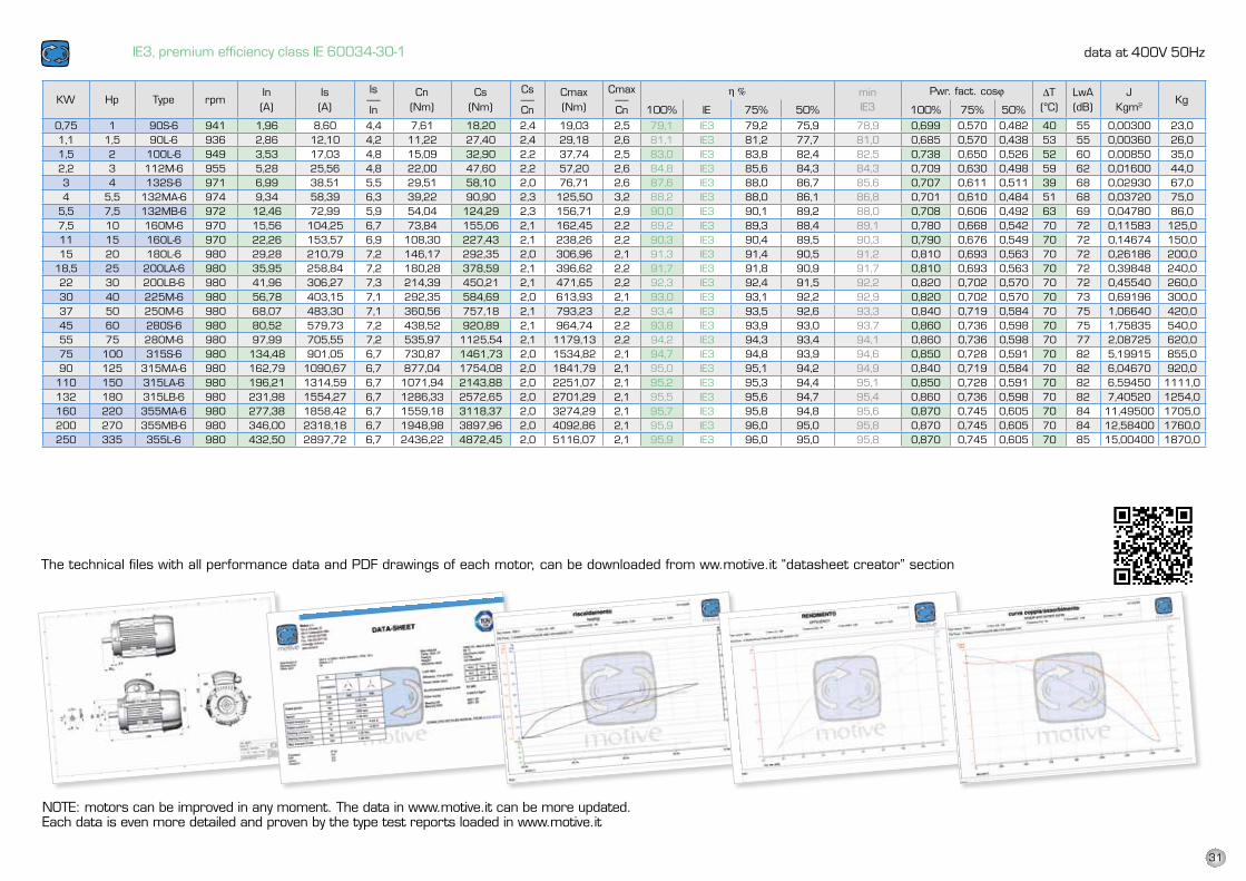
0,75 1 90S-6 941 1,96 8,60 4,4 7,61 18,20 2,4 19,03 2,5 79,1 IE3 79,2 75,9 78,9 0,699 0,570 0,482 40 55 0,00300 23,01,1 1,5 90l-6 936 2,86 12,10 4,2 11,22 27,40 2,4 29,18 2,6 81,1 IE3 81,2 77,7 81,0 0,685 0,570 0,438 53 55 0,00360 26,01,5 2 100l-6 949 3,53 17,03 4,8 15,09 32,90 2,2 37,74 2,5 83,0 IE3 83,8 82,4 82,5 0,738 0,650 0,526 52 60 0,00850 35,02,2 3 112M-6 955 5,28 25,56 4,8 22,00 47,60 2,2 57,20 2,6 84,8 IE3 85,6 84,3 84,3 0,709 0,630 0,498 59 62 0,01600 44,03 4 132S-6 971 6,99 38,51 5,5 29,51 58,10 2,0 76,71 2,6 87,6 IE3 88,0 86,7 85,6 0,707 0,611 0,511 39 68 0,02930 67,04 5,5 132MA-6 974 9,34 58,39 6,3 39,22 90,90 2,3 125,50 3,2 88,2 IE3 88,0 86,1 86,8 0,701 0,610 0,484 51 68 0,03720 75,0
5,5 7,5 132MB-6 972 12,46 72,99 5,9 54,04 124,29 2,3 156,71 2,9 90,0 IE3 90,1 89,2 88,0 0,708 0,606 0,492 63 69 0,04780 86,07,5 10 160M-6 970 15,56 104,25 6,7 73,84 155,06 2,1 162,45 2,2 89,2 IE3 89,3 88,4 89,1 0,780 0,668 0,542 70 72 0,11583 125,011 15 160l-6 970 22,26 153,57 6,9 108,30 227,43 2,1 238,26 2,2 90,3 IE3 90,4 89,5 90,3 0,790 0,676 0,549 70 72 0,14674 150,015 20 180l-6 980 29,28 210,79 7,2 146,17 292,35 2,0 306,96 2,1 91,3 IE3 91,4 90,5 91,2 0,810 0,693 0,563 70 72 0,26186 200,0
18,5 25 200lA-6 980 35,95 258,84 7,2 180,28 378,59 2,1 396,62 2,2 91,7 IE3 91,8 90,9 91,7 0,810 0,693 0,563 70 72 0,39848 240,022 30 200lB-6 980 41,96 306,27 7,3 214,39 450,21 2,1 471,65 2,2 92,3 IE3 92,4 91,5 92,2 0,820 0,702 0,570 70 72 0,45540 260,030 40 225M-6 980 56,78 403,15 7,1 292,35 584,69 2,0 613,93 2,1 93,0 IE3 93,1 92,2 92,9 0,820 0,702 0,570 70 73 0,69196 300,037 50 250M-6 980 68,07 483,30 7,1 360,56 757,18 2,1 793,23 2,2 93,4 IE3 93,5 92,6 93,3 0,840 0,719 0,584 70 75 1,06640 420,045 60 280S-6 980 80,52 579,73 7,2 438,52 920,89 2,1 964,74 2,2 93,8 IE3 93,9 93,0 93,7 0,860 0,736 0,598 70 75 1,75835 540,055 75 280M-6 980 97,99 705,55 7,2 535,97 1125,54 2,1 1179,13 2,2 94,2 IE3 94,3 93,4 94,1 0,860 0,736 0,598 70 77 2,08725 620,075 100 315S-6 980 134,48 901,05 6,7 730,87 1461,73 2,0 1534,82 2,1 94,7 IE3 94,8 93,9 94,6 0,850 0,728 0,591 70 82 5,19915 855,090 125 315MA-6 980 162,79 1090,67 6,7 877,04 1754,08 2,0 1841,79 2,1 95,0 IE3 95,1 94,2 94,9 0,840 0,719 0,584 70 82 6,04670 920,0
110 150 315lA-6 980 196,21 1314,59 6,7 1071,94 2143,88 2,0 2251,07 2,1 95,2 IE3 95,3 94,4 95,1 0,850 0,728 0,591 70 82 6,59450 1111,0132 180 315lB-6 980 231,98 1554,27 6,7 1286,33 2572,65 2,0 2701,29 2,1 95,5 IE3 95,6 94,7 95,4 0,860 0,736 0,598 70 82 7,40520 1254,0160 220 355MA-6 980 277,38 1858,42 6,7 1559,18 3118,37 2,0 3274,29 2,1 95,7 IE3 95,8 94,8 95,6 0,870 0,745 0,605 70 84 11,49500 1705,0200 270 355MB-6 980 346,00 2318,18 6,7 1948,98 3897,96 2,0 4092,86 2,1 95,9 IE3 96,0 95,0 95,8 0,870 0,745 0,605 70 84 12,58400 1760,0250 335 355l-6 980 432,50 2897,72 6,7 2436,22 4872,45 2,0 5116,07 2,1 95,9 IE3 96,0 95,0 95,8 0,870 0,745 0,605 70 85 15,00400 1870,0
IE3, premium efficiency class IE 60034-30-1
NOTE: motors can be improved in any moment. The data in www.motive.it can be more updated.Each data is even more detailed and proven by the type test reports loaded in www.motive.it
IE3 motors can be distinguished by the colour of their terminal box cap and the plate data
KW HP Type rpmIs----In
Cn(Nm)
Cs----Cn
Cmax----Cn
In(A)
LwA
(dB)
J
Kgm2 KgIs(A)
Cs(Nm)
∆T
(°C)
Cmax(Nm)
η % 100% IE 75% 50%
Pwr. fact. cosϕ100% 75% 50%
minIE3
The technical files with all performance data and PDF drawings of each motor, can be downloaded from ww.motive.it “datasheet creator” section
data at 400V 50Hz
KW Hp Type rpmIn(A)
Is(A)
Is-----In
Cn(Nm)
Cs(Nm)
Cs-----Cn
Cmax(Nm)
Cmax-----Cn
h % minIE3
Pwr. fact. cosj DT(°C)
LwA(dB)
JKgm2
Kg100% IE 75% 50% 100% 75% 50%
31
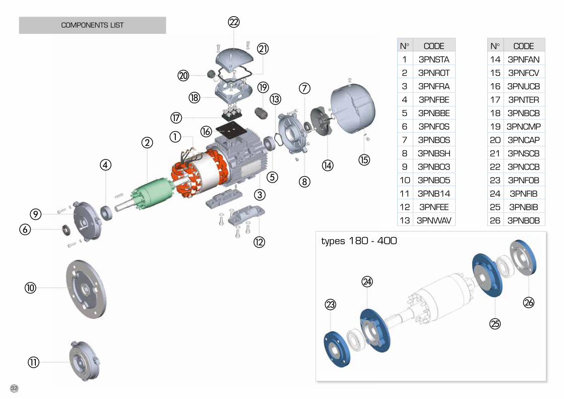
COMPONENTS LIST
N°
1
2
3
4
5
6
7
8
9
10
11
12
13
CODE
3PNSTA
3PNROT
3PNFRA
3PNFBE
3PNBBE
3PNFOS
3PNBOS
3PNBSH
3PNB03
3PNB05
3PNB14
3PNFEE
3PNWAV
N°
14
15
16
17
18
19
20
21
22
23
24
25
26
CODE
3PNFAN
3PNFCV
3PNUCB
3PNTER
3PNBCB
3PNCMP
3PNCAP
3PNSCB
3PNCCB
3PNFOB
3PNFIB
3PNBIB
3PNBOB
types 180 - 400
32
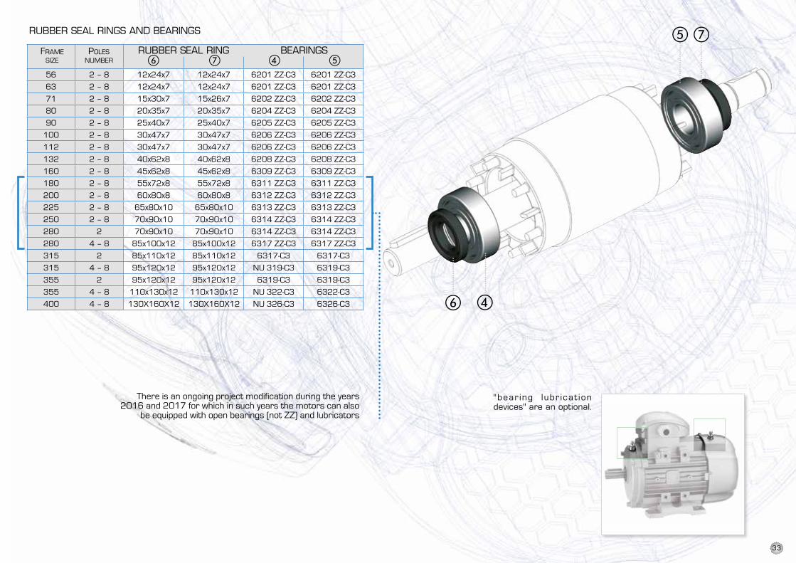
56 2 – 8 12x24x7 12x24x7 6201 ZZ-C3 6201 ZZ-C3
63 2 – 8 12x24x7 12x24x7 6201 ZZ-C3 6201 ZZ-C3
71 2 – 8 15x30x7 15x26x7 6202 ZZ-C3 6202 ZZ-C3
80 2 – 8 20x35x7 20x35x7 6204 ZZ-C3 6204 ZZ-C3
90 2 – 8 25x40x7 25x40x7 6205 ZZ-C3 6205 ZZ-C3
100 2 – 8 30x47x7 30x47x7 6206 ZZ-C3 6206 ZZ-C3
112 2 – 8 30x47x7 30x47x7 6206 ZZ-C3 6206 ZZ-C3
132 2 – 8 40x62x8 40x62x8 6208 ZZ-C3 6208 ZZ-C3
160 2 – 8 45x62x8 45x62x8 6309 ZZ-C3 6309 ZZ-C3
180 2 – 8 55x72x8 55x72x8 6311 ZZ-C3 6311 ZZ-C3
200 2 – 8 60x80x8 60x80x8 6312 ZZ-C3 6312 ZZ-C3
225 2 – 8 65x80x10 65x80x10 6313 ZZ-C3 6313 ZZ-C3
250 2 – 8 70x90x10 70x90x10 6314 ZZ-C3 6314 ZZ-C3
280 2 70x90x10 70x90x10 6314 ZZ-C3 6314 ZZ-C3
280 4 – 8 85x100x12 85x100x12 6317 ZZ-C3 6317 ZZ-C3
315 2 85x110x12 85x110x12 6317-C3 6317-C3
315 4 – 8 95x120x12 95x120x12 NU 319-C3 6319-C3
355 2 95x120x12 95x120x12 6319-C3 6319-C3
355 4 – 8 110x130x12 110x130x12 NU 322-C3 6322-C3
400 4 – 8 130X160X12 130X160X12 NU 326-C3 6326-C3
RUBBER SEAL RINGS AND BEARINGS
FRAME POLES SIZE NUMBER � � � �
RUBBER SEAL RING BEARINGS
2 bearings lubricationdevices on the front andthe back shield areprovided in motors fromsize 180 and up.Other motors mountstaunch bearings pre-lubricated for life.Motors 180-400 arealready supplied withlithium grease.
"bear ing lubr icat iondevices" are an optionalon motors size 56-160.
"bear ing lubr icat iondevices" are an optional.
There is an ongoing project modification during the years 2016 and 2017 for which in such years the motors can also
be equipped with open bearings (not ZZ) and lubricators
33
ALL DATA HAVE BEEN WRITTEN AND CHECKED WITH THE GREATEST CARE.WE DO NOT TAKE ANY RESPONSIBILITY FOR POSSIBLE ERRORS OR OMISSIONS.MOTIVE CAN CHANGE THE CHARACTERISTICS OF THE SOLD ITEMS ON HIS FIRM OPINIONAND IN EVERY MOMENT.
TERMS OF SALE AND GUARANTEE
ARTICLE 3DELIVERY
3.1. Any liability for damages ensuingfrom total or partial delayed or faileddelivery, shall be excluded.
3.2. Unless differently communicatedby written to the Client, the transportterms have to be intended ex-works
a) To supply the Buyer with products of thesame type and quality as those havingproven defective and not complying withagreements, free ex-works; in aforesaidcase, Motive shall have the right torequest, at the Buyer’s charge, earlyreturn of defective goods, which shallbecome Motive’s property;
b) To repair, at its charge, the defectiveproduct or to modify the product whichdoes not comply with agreements, byperforming aforesaid action at itsfacilities; in aforesaid cases, all costsregarding product transport shall besustained by the Buyer.
c) To send spare parts free of charge:all costs regarding product transportshall be sustained by the Buyer.
1.3 The guarantee herein shall assimilate andreplace legal guarantees for defects anddiscrepancies, and shall exclude any othereventual Motive liability, however caused bysupplied products; in particular, the Buyershall have no right to submit any further claims.Motive shall not be liable for the enforcementof any further claims, as of the date theguarantee’s term of validity expires.
ARTICLE 2CLAIMS
2.1. Without prejudice to the applicationof provisions in Law, dated June 21,1971, and as per Article 1:Claims, regarding quantity, weight, grossweight and colour, or claims regardingfaults and defects in qual ity orcompliance, and which the Buyer maydiscover on goods delivery, shall besubmitted by a max. 7 days of aforesaiddiscovery, under penalty of nullity.
ARTICLE 1GARANTEE
1.1. Barring written agreements,entered into between the parties heretoeach time, Motive hereby guaranteescompliance of products supplied andcompliance with specific agreements.The guarantee for defects shall berestricted to product defects followingdesign, materials or manufacturingdefects leading back to Motive.
The Guarantee shall not include:
faults or damages ensuing fromtransport., faults or damagesensuing from installation defects;incompetent use of the product, orany other unsuitable use.
tampering or damages ensuing fromuse by non - authorised staff and/oruse of non - original parts and/orspare parts;Defects and/or damages ensuing fromchemical agents and/or atmosphericphenomena (e.g. burnt out material,etc.);routine maintenance and requiredaction or checks;
Products lacking a plate or havinga tampered plate.
1.2. Returns to credit or replace will beaccepted only in exceptional cases; Howeverreturns of goods already used to credit orreplace won’t be accepted in any case.The guarantee shall be effective for all Motiveproducts, with a term of validity of 12 months,starting from the date of shipment.The guarantee shall be subject to specificwritten request for Motive to takeaction,according to statements, as describedat the paragraphs hereinbelow. By virtue ofaforesaid approval, and as regards the claim,Motive shall be bound, at its discretion, andwithin a reasonable time-limit,to alternativelytake the following action:
ARTICLE 4PAYMENT
4.1. Any delayed or irregular paymentsshall entitle Motive to cancel ongoingagreements, including agreements whichdo not regard the payments at issue,as well as entitling Motive to claimdamages, if any. Motive shall, however,have the right, as of the payment’s duedate and without placing in arrears, toclaim interest for arrears, to the extentof the discount rate in force in Italy,increased by 5 points. Motive shall alsohave the right to withhold material underrepair for replacement. In the case offailed payment, Motive shall have theright to cancel all guarantees onmaterials, as regards the insolventClient.
4.2. The Buyer shall be bound tocomplete payment, including caseswhereby claims or disputes areunderway.
DoWNloAD the teChNiCAl mANuAl from
WWW.motive.it
*
*
*
*
34
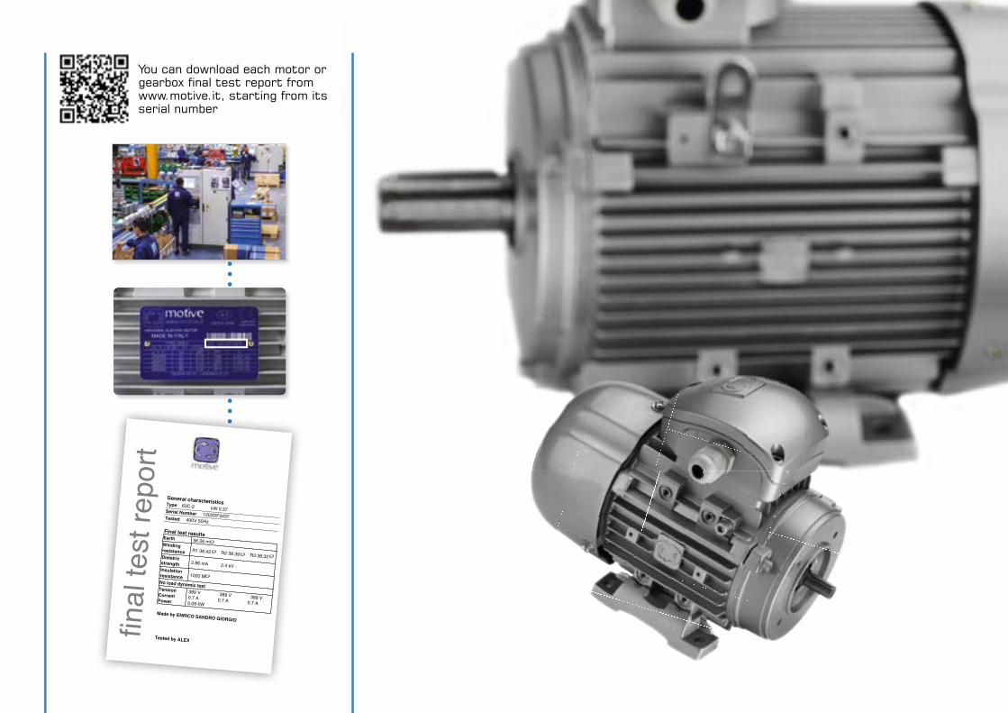
final
test
repo
rt
General characteristicsType 63C-2 kW 0.37Serial Number 1203DF3437Tested 400V 50Hz
Final test resultsEarth 56.26 mWindingresistance
R1 38.42 R2 38.39 R3 38.32 Dieletricstrength
2.86 mA 2.4 kVInsulationresistance
1000 MNo load dynamic testTensionCurrentPower
389 V 389 V 389 V 0.7 A 0.7 A 0.7 A 0.09 kW
Made by ENRICO SANDRO GIORGIO
Tested by ALEX
You can download each motor or gearbox final test report from www.motive.it, starting from its serial number
Motive s.r.l.
Via Le Ghiselle, 20
25014 Castenedolo (BS) - Italy
Tel.: +39.030.2677087 - Fax: +39.030.2677125
web site: www.motive.it
e-mail: [email protected]
LOO
KS
GOOD, PERFORMS BETTE
R
ASK OUR FURTHER CATALOGUES:
TECH
NIC
AL
CATA
LOG
UE
DEL
PH
I SER
IES J
UL
16
REV.
13
AREA DISTRIBUTOR
BOX SERIES WORMGEAR UNITS
BOX SERIES WORMGEAR UNITS
BOX SERIES WORMGEAR UNITS
STON SHAFT MOSTON SHAFT MOSTON SHAFT MOSTON SHAFT MOSTON SHAFT MOSTON SHAFT MOSTON SHAFT MOSTON SHAFT MOSTON SHAFT MOSTON SHAFT MOSTON SHAFT MOSTON SHAFT MOUNTEDUNTEDUNTEDUNTEDUNTEDUNTEDUNTEDUNTEDUNTEDUNTEDUNTEDUNTED GEARBOXGEARBOXGEARBOXGEARBOXGEARBOXGEARBOXGEARBOXGEARBOXGEARBOXGEARBOXGEARBOXGEARBOXGEARBOXGEARBOXGEARBOXGEARBOXGEARBOXGEARBOXGEARBOXGEARBOXGEARBOXGEARBOXGEARBOXGEARBOXGEARBOXGEARBOXGEARBOX
ROBUS in-line hROBUS in-line hROBUS in-line helical geaelical geaelical geaRBORBORBORBORBORBORBORBORBORBORBORBOROBUS in-line hROBUS in-line hROBUS in-line hROBUS in-line hROBUS in-line hROBUS in-line hROBUS in-line hROBUS in-line hROBUS in-line hROBUS in-line hROBUS in-line hROBUS in-line hROBUS in-line hROBUS in-line hROBUS in-line hROBUS in-line hROBUS in-line hROBUS in-line hVARIABLE SPEED D
VARIABLE SPEED DVARIABLE SPEED DVARIABLE SPEED DVARIABLE SPEED DVARIABLE SPEED DVARIABLE SPEED DVARIABLE SPEED DVARIABLE SPEED DVARIABLE SPEED DVARIABLE SPEED DVARIABLE SPEED DVARIABLE SPEED DVARIABLE SPEED DVARIABLE SPEED DVARIABLE SPEED DVARIABLE SPEED DVARIABLE SPEED DVARIABLE SPEED DVARIABLE SPEED DVARIABLE SPEED DVARIABLE SPEED DVARIABLE SPEED DVARIABLE SPEED DVARIABLE SPEED DVARIABLE SPEED DVARIABLE SPEED DVARIABLE SPEED DVARIABLE SPEED DVARIABLE SPEED DVARIABLE SPEED DVARIABLE SPEED DVARIABLE SPEED DVARIABLE SPEED DVARIABLE SPEED DVARIABLE SPEED DVARIABLE SPEED DVARIABLE SPEED DVARIABLE SPEED DVARIABLE SPEED DVARIABLE SPEED DVARIABLE SPEED DVARIABLE SPEED DVARIABLE SPEED DVARIABLE SPEED DVARIABLE SPEED DVARIABLE SPEED DVARIABLE SPEED DRIVE NEO-WRIVE NEO-WRIVE NEO-WRIVE NEO-WRIVE NEO-WRIVE NEO-WRIVE NEO-WRIVE NEO-WRIVE NEO-WRIVE NEO-WRIVE NEO-WRIVE NEO-WRIVE NEO-WRIVE NEO-WRIVE NEO-WRIVE NEO-WRIVE NEO-WRIVE NEO-WRIVE NEO-WRIVE NEO-WRIVE NEO-WRIVE NEO-WRIVE NEO-WRIVE NEO-WRIVE NEO-WRIVE NEO-WRIVE NEO-WRIVE NEO-WRIVE NEO-WRIVE NEO-WRIVE NEO-WRIVE NEO-WRIVE NEO-WRIVE NEO-WRIVE NEO-WRIVE NEO-WRIVE NEO-WRIVE NEO-WRIVE NEO-WRIVE NEO-WRIVE NEO-WRIVE NEO-WRIVE NEO-WRIVE NEO-WRIVE NEO-WRIVE NEO-WRIVE NEO-WRIVE NEO-WRIVE NEO-WRIVE NEO-WRIVE NEO-WRIVE NEO-WRIVE NEO-WRIVE NEO-WRIVE NEO-WRIVE NEO-WRIVE NEO-WRIVE NEO-WRIVE NEO-WRIVE NEO-WIIIIII
ROBUS in-line hROBUS in-line hROBUS in-line hIROBUS in-line hROBUS in-line hROBUS in-line hIROBUS in-line hROBUS in-line hROBUS in-line hIROBUS in-line hROBUS in-line hROBUS in-line hIIIFFFFFFFFFIIIIIIIII
ENDURO BEVEL HENDURO BEVEL HENDURO BEVEL HENDURO BEVEL HENDURO BEVEL HENDURO BEVEL HENDURO BEVEL HENDURO BEVEL HENDURO BEVEL HENDURO BEVEL HENDURO BEVEL HENDURO BEVEL HENDURO BEVEL HENDURO BEVEL HENDURO BEVEL HENDURO BEVEL HENDURO BEVEL HENDURO BEVEL HENDURO BEVEL HENDURO BEVEL HENDURO BEVEL HELICAL GEARBOX
ELICAL GEARBOXELICAL GEARBOXELICAL GEARBOXELICAL GEARBOXELICAL GEARBOXELICAL GEARBOXELICAL GEARBOXELICAL GEARBOXELICAL GEARBOXELICAL GEARBOXELICAL GEARBOXELICAL GEARBOXELICAL GEARBOXELICAL GEARBOX
ENDURO BEVEL HENDURO BEVEL HENDURO BEVEL HENDURO BEVEL HENDURO BEVEL HENDURO BEVEL HENDURO BEVEL HENDURO BEVEL HENDURO BEVEL HENDURO BEVEL HENDURO BEVEL HENDURO BEVEL HENDURO BEVEL HENDURO BEVEL HENDURO BEVEL HENDURO BEVEL HENDURO BEVEL HENDURO BEVEL HENDURO BEVEL HENDURO BEVEL HENDURO BEVEL H
G E N E R A L CG E N E R A L CG E N E R A L CG E N E R A L CG E N E R A L CG E N E R A L CG E N E R A L CG E N E R A L CG E N E R A L CG E N E R A L CG E N E R A L CG E N E R A L C A T A L O G U E
A T A L O G U EA T A L O G U EA T A L O G U EA T A L O G U EA T A L O G U EA T A L O G U EA T A L O G U EA T A L O G U EA T A L O G U EA T A L O G U EA T A L O G U EA T A L O G U EA T A L O G U EA T A L O G U EA T A L O G U EA T A L O G U EA T A L O G U EA T A L O G U EA T A L O G U EA T A L O G U EA T A L O G U EA T A L O G U EA T A L O G U EA T A L O G U EA T A L O G U EA T A L O G U EA T A L O G U EA T A L O G U EA T A L O G U EA T A L O G U EA T A L O G U EA T A L O G U EA T A L O G U EA T A L O G U EA T A L O G U EA T A L O G U EA T A L O G U EA T A L O G U EA T A L O G U EA T A L O G U EA T A L O G U EA T A L O G U EA T A L O G U EA T A L O G U EA T A L O G U EA T A L O G U EA T A L O G U EA T A L O G U EA T A L O G U EA T A L O G U EA T A L O G U EA T A L O G U EA T A L O G U EA T A L O G U EA T A L O G U EA T A L O G U EA T A L O G U EA T A L O G U EA T A L O G U EA T A L O G U EA T A L O G U EA T A L O G U EA T A L O G U EA T A L O G U EA T A L O G U EA T A L O G U EA T A L O G U EA T A L O G U EA T A L O G U EA T A L O G U EA T A L O G U EA T A L O G U EA T A L O G U EA T A L O G U EA T A L O G U EA T A L O G U EA T A L O G U EA T A L O G U EA T A L O G U EA T A L O G U E