Embed Size (px)
Citation preview

Commercial valve solutions
2
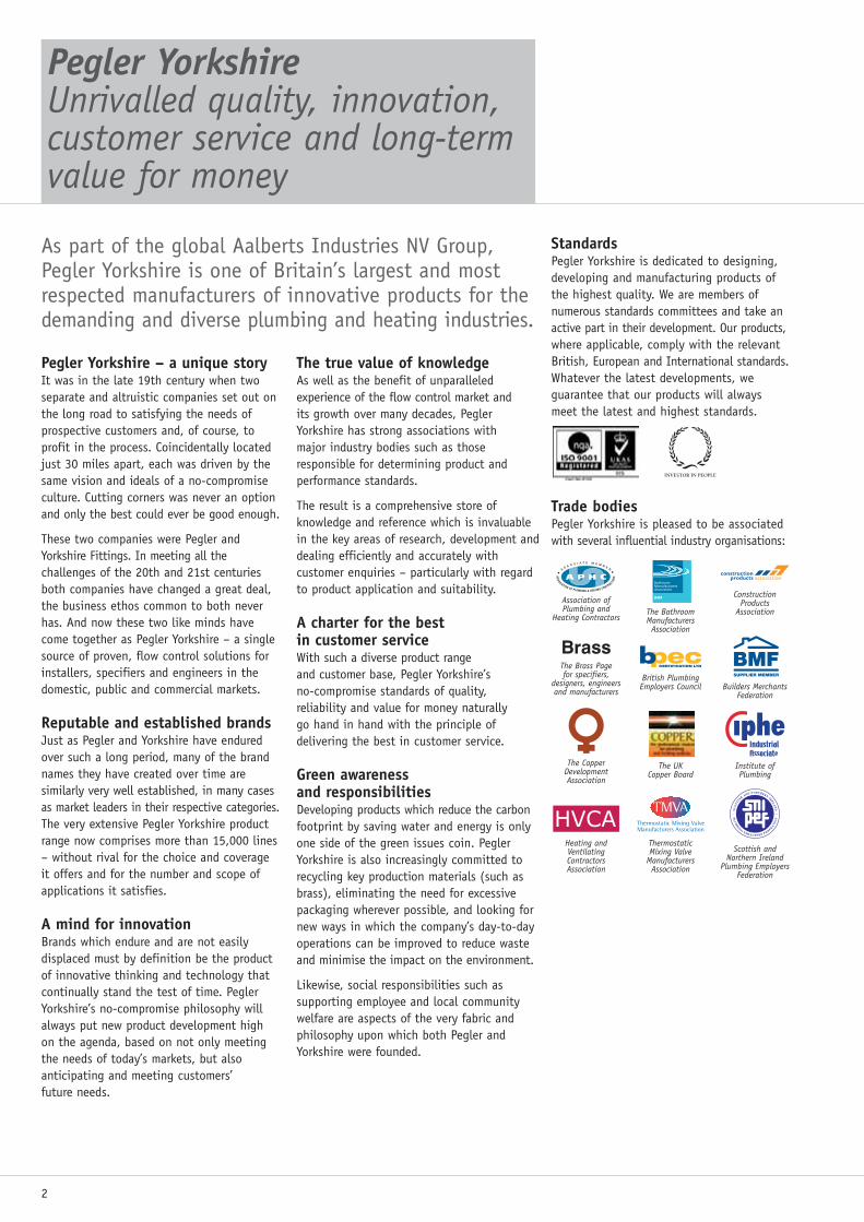
Pegler YorkshireUnrivalled quality, innovation,customer service and long-termvalue for money
As part of the global Aalberts Industries NV Group,Pegler Yorkshire is one of Britain’s largest and mostrespected manufacturers of innovative products for thedemanding and diverse plumbing and heating industries.
Pegler Yorkshire – a unique storyIt was in the late 19th century when twoseparate and altruistic companies set out onthe long road to satisfying the needs ofprospective customers and, of course, toprofit in the process. Coincidentally locatedjust 30 miles apart, each was driven by thesame vision and ideals of a no-compromiseculture. Cutting corners was never an optionand only the best could ever be good enough.
These two companies were Pegler andYorkshire Fittings. In meeting all thechallenges of the 20th and 21st centuriesboth companies have changed a great deal,the business ethos common to both neverhas. And now these two like minds havecome together as Pegler Yorkshire – a singlesource of proven, flow control solutions forinstallers, specifiers and engineers in thedomestic, public and commercial markets.
Reputable and established brandsJust as Pegler and Yorkshire have enduredover such a long period, many of the brandnames they have created over time aresimilarly very well established, in many casesas market leaders in their respective categories.The very extensive Pegler Yorkshire productrange now comprises more than 15,000 lines– without rival for the choice and coverageit offers and for the number and scope ofapplications it satisfies.
A mind for innovationBrands which endure and are not easilydisplaced must by definition be the productof innovative thinking and technology thatcontinually stand the test of time. PeglerYorkshire’s no-compromise philosophy willalways put new product development highon the agenda, based on not only meetingthe needs of today’s markets, but alsoanticipating and meeting customers’ future needs.
The true value of knowledgeAs well as the benefit of unparalleledexperience of the flow control market and its growth over many decades, Pegler Yorkshire has strong associations with major industry bodies such as thoseresponsible for determining product andperformance standards.
The result is a comprehensive store ofknowledge and reference which is invaluablein the key areas of research, development anddealing efficiently and accurately withcustomer enquiries – particularly with regardto product application and suitability.
A charter for the best in customer serviceWith such a diverse product range and customer base, Pegler Yorkshire’s no-compromise standards of quality, reliability and value for money naturally go hand in hand with the principle ofdelivering the best in customer service.
Green awareness and responsibilitiesDeveloping products which reduce the carbonfootprint by saving water and energy is onlyone side of the green issues coin. PeglerYorkshire is also increasingly committed torecycling key production materials (such asbrass), eliminating the need for excessivepackaging wherever possible, and looking fornew ways in which the company’s day-to-dayoperations can be improved to reduce wasteand minimise the impact on the environment.
Likewise, social responsibilities such assupporting employee and local communitywelfare are aspects of the very fabric andphilosophy upon which both Pegler andYorkshire were founded.
StandardsPegler Yorkshire is dedicated to designing,developing and manufacturing products ofthe highest quality. We are members ofnumerous standards committees and take anactive part in their development. Our products,where applicable, comply with the relevantBritish, European and International standards.Whatever the latest developments, weguarantee that our products will alwaysmeet the latest and highest standards.
Trade bodiesPegler Yorkshire is pleased to be associatedwith several influential industry organisations:
ConstructionProducts
Association
Heating andVentilatingContractorsAssociation
Association ofPlumbing and
Heating ContractorsThe BathroomManufacturersAssociation
Builders MerchantsFederation
British PlumbingEmployers Council
The Brass Page for specifiers,
designers, engineersand manufacturers
The CopperDevelopmentAssociation
Institute ofPlumbing
Scottish andNorthern Ireland
Plumbing EmployersFederation
Thermostatic Mixing Valve
ManufacturersAssociation
The UK Copper Board
pecCERTIFICATION LTD
Brass
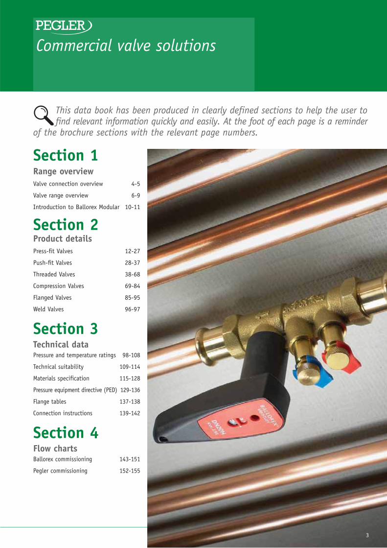
This data book has been produced in clearly defined sections to help the user tofind relevant information quickly and easily. At the foot of each page is a reminder
of the brochure sections with the relevant page numbers.
Commercial valve solutions
Section 1Range overviewValve connection overview 4-5
Valve range overview 6-9
Introduction to Ballorex Modular 10-11
Section 2Product detailsPress-fit Valves 12-27
Push-fit Valves 28-37
Threaded Valves 38-68
Compression Valves 69-84
Flanged Valves 85-95
Weld Valves 96-97
Section 3Technical dataPressure and temperature ratings 98-108
Technical suitability 109-114
Materials specification 115-128
Pressure equipment directive (PED) 129-136
Flange tables 137-138
Connection instructions 139-142
Section 4Flow chartsBallorex commissioning 143-151
Pegler commissioning 152-155
3

4 1 Range overview 2 Product details 3 Technical data 4 Flow charts
Commercial valve solutionsValve connection overview
Press-fit connectionsA quick, clean, heat-free jointing technologyfor copper, stainless steel and carbon steelpipe work up to 54mm. Unique ‘Leak BeforePress’ feature on all connection sizes up to54mm (DN50 Screwed valves).
� Simple and fast, reduces time on site withgood repetition of joint quality
� Uses one simple, inexpensive tool with no additional materials
� Intrinsically clean, no flushing to remove residues
� No hot works permits and associatedinsurance implications or health & safety hazards
� Suitable for both heating, chilled andpotable water (where WRAS Approved)
� Valves available in Bronze, Duplex Brassand DZR to suit operating duty.
Features� Unique design and using bronze permits
jointing of all materials – one connectorfits all
Push-fit connectionsA fast, cost effective jointing system idealfor copper and steel (stainless and carbon),with joints created in seconds withoutcomplex clamping, the application of heatand extended preparation and adhesivecuring delays.
Features� Major time savings� Permits rapid installation and removal
(if required)� No special tools required� Heat-free for enhanced safety, with no
localised annealing� No carbon deposits, reduced corrosion risk� Perfectly clean internal bore, less
finishing/cleaning� Valves available in Bronze, Duplex Brass
and DZR to suit operating duty.
ThreadedconnectionsA heat free jointing method particularlysuited to smaller, fixed systems usingEN10255 mild steel tube, where theinstallation is expected to remainunchanged for long periods of time.Products are available (dependent on style)for three types of thread.
Features� BS EN 10226 (BS21) taper thread� ISO 228 parallel thread� ANSI (NPT) American taper thread� Suitable for heating, cooling and potable
water applications (where materialsuitability and relevant standards areapplicable or WRAS Approved is required)
� Valves available in Bronze, Duplex Brassand DZR.
Pegler Yorkshire has been a major force in valves and fittings for over 100 yearsand our new commercial valves package for the HVAC market is built upon theunique strengths in design and manufacture accumulated over this period.As well as offering traditional threaded andcompression connections the Pegler commercialvalves range also offers the new connectiontechnology of press-fit and push-fit jointingand sets a new standard for the industry.
When pipe sizing reaches 2” sizes andabove, particular consideration should begiven to material selection. The Peglercommercial valves package also offers castiron and steel valves in a range of types
and sizes. Steel valve applications arefocused on district heating but also formpart of the Pegler commercial package with flanged and welded end valves being available.

1 Range overview 2 Product details 3 Technical data 4 Flow charts 5
1
CompressionconnectionsA traditional heat free mechanical jointingsystem making it easy to undo and re-makejoints. Ideal for applications wheremaintenance and repair are required.
Features� Major time saving compared to soldering
and brazing� Intrinsically clean bore, less
flushing/cleaning� No hot works permits and associated
insurance implications� Suitable for heating, cooling and potable
water applications (where materialsuitability and relevant standards areapplicable or WRAS Approved is required)
� Valves available in Duplex Brass, DZR and Gunmetal.
Flanged connectionsA robust jointing mechanism for pipediameters of DN65 and upwards. Ideally suited to applications where pipework is likely to be dismantled for valvemaintenance/replacement. Very quick and easy to undo and re-make joints orwhere pre fabrication is the chosenconstruction method.
Features� Valves available in Steel and Cast Iron in
gate, ball, butterfly, swing and dual platecheck valves
� Suitable for heating, cooling and potablewater applications (where materialsuitability and relevant standards are applicable).
Weld connectionsA high integrity, leak proof jointing methodideal for pipelines where operatingtemperatures and pressures determine thatwelding is the optimal jointing method.Ideal for systems where maintenance is not required.
Features� Valves available in Steel � Available in weld prepared and extended
connection piece tail styles� Ball valves available to PN40� Live weld in tapping kits and
valves available.

6 1 Range overview 2 Product details 3 Technical data 4 Flow charts
Commercial valve solutionsValve range overview
Commissioning valvesA class leading, comprehensive range of fixedorifice double regulating commissioningvalves including high performance BallorexVenturi principle and traditional obliquepattern screwed and flanged valves.
Features� DN15 – DN300 size range� Choice of press-fit, push-fit, threaded,
compression and flanged connections� Range includes Dynamic valves with direct
flow verification and utilizing the highlyaccurate Venturi principle and actuators
� Low, standard and high flow optionsavailable (DN15 – DN20)
� DN15 – DN50 manufactured in DZR� WRAS approval *where stated.
Quarter turn ball valvesCompact, easy to operate, quarter turn ballvalves in the Pegler Commercial range aredesigned for long, trouble free service.Available in lever, ‘T’ handle and keyoperated lockshield designs, they provide anideal means of isolating a range of fluids inpipe lines.
Features� DN15 – DN100 size range� PN16, PN25, PN40 pressure rated
options available� Available in Brass, Chrome Plated Brass
unplated DZR� Full bore� Choice of press-fit, push-fit, threaded and
compression connections� Optional locking devices available.
Gate valvesOptimally designed, traditional full way gatevalves either in wheel head or lockshield areideal for isolating a range of fluids in pipe lines.
Features� DN15 – DN100 size range� Choice of press-fit, push-fit, threaded,
compression and flanged connections *where applicable
� Brass, DZR, Bronze and Cast Ironconstruction materials.

1 Range overview 2 Product details 3 Technical data 4 Flow charts 7
1Ballomax ball valvesFull bore Ballomax steel ball valves are idealfor district heating systems, general heatingsystems and a host of industrial applications.
Features� DN15 – DN400 standard size range� PN16, PN25, PN40 pressure rating available� Full welded, full bore, ball seal compensated,
steel valves� Screwed, weld ends and flanged connections
available� Hot (live tapping kits) available (DN15 –
DN100 branch size)� Lever, lockshield, gearbox, manhole, electric
actuation and mobile operation available.
Butterfly valvesButterfly valves are ideal where a slimprofile, low weight isolation and throttlingis required on DN65 and above pipe sizes.
Features� DN65 – DN300 standard size range
(larger sizes are available)� PN16 rated� Fully lugged and semi-lugged options
available� Stainless steel disc as standard� Lever and gearbox operation options.
Check valvesAn extensive range of single and doublevalves in Bronze, Brass and Cast Iron.Designs include swing, horizontal lift, dualplate and spring/foot – as well as stainlesssteel wafer pattern.
Features� DN15 – DN300 standard size range� PN16 ratings for flange, ratings to PN32
on thread valves� Choice of press-fit, push-fit, threaded,
compression and flanged connections� Bronze, Brass, DZR and Cast Iron
construction materials� WRAS approval *where stated.

8 1 Range overview 2 Product details 3 Technical data 4 Flow charts
Commercial valve solutionsValve range overview
StrainersY-pattern strainers with mesh filters providehighly effective protection from systemdebris causing damage to sensitive controlsand valves in a pipe line. A heavy patternstrainer with capped test points is includedin the range for measuring pressure drops inidentifying the need for mesh cleaning.
Features� DN15 – DN300 size range� PN16 – 32 ratings� Y-pattern and isolating options available� Choice of press-fit, push-fit, threaded and
flanged connections * where applicable� Stainless steel mesh as standard� Cast Iron Y-pattern strainer.
Globe valvesGlobe valves offer the ideal solution wherecontrol or throttling is required to controlor regulate the flow of fluids in a pipe line.
Features� DN8 – DN50 size range� PN32 rated� Renewable or metal disc options available� Bronze construction materials.
Thermal circulationvalvesPegler thermostatically-controlled circulationvalves permit water to flow in closed,pumped domestic services ensuring effectiveflow temperatures and, helping to prevent thehealth dangers posed by Legionella. Alsominimizes scalding and water consumption.
Features� DN15 – DN25 size range� PN16 rated� Bronze construction� Female screwed and male screwed
connections available� User set, automatic thermal balancing and
circulation functions� Isolation, drain off and regulating
contained within one valve� Accessories include, custom insulation
jackets and temperature gauge.

1 Range overview 2 Product details 3 Technical data 4 Flow charts 9
1
Draincocks andancillariesPegler draincocks, gland and ball drainvalves offer a wide range of solutions for draining down pipe lines or to take draw offs.
Features� DN15 – DN25 size range� Screwed connections available� Bronze, Brass and DZR materials of
construction available.
Ballofix isolatingservice valvesBallofix in-line isolation valves offer a wide range of both body styles and endconnections for potable and hot and cold water, oil and compressed air and gas services.
Features� DN8 – DN25 size range, 15mm to 28mm� PN10 rated � Press-fit, push-fit, compression and
threaded connections available� Filter options available� DZR brass unplated and chrome
plated options.

10 1 Range overview 2 Product details 3 Technical data 4 Flow charts
Commercial valve solutionsIntroduction to Ballorex Modular
Connections are made via female BSP,Tectite Pro or compression joints to themain pipework system; and via compressionfittings – suitable for copper or multilayerpipe systems – to the terminal unit.
Advantages ofBallorex ModularThe primary advantage of the BallorexModular system is its ability to be suppliedin a wide variety of configurations in linewith the specifiers’ particular needs. Anycomponent combination can be requested,and will be assembled specifically to meetindividual requirements.
Other advantages of Ballorex Modular include:
Operational capabilities� Can carry out any water flow control
function required by a terminal unit –forward flush, bypass or backflush.
� The flow rate can be adjusted and setthrough the Ballorex Venturicommissioning valve.
Installation� Installation planning is straightforward as
all functions are contained within one unit.� Requires no on-site or in situ adaptation
prior to installation.� A compact system, due to the valves’
multifunctional capabilities and the ability to specify the flow and returncentre spacing.
Maintenance and practicalities� Valves with extended spindles contain a
unique integral non-rotating outer spindle.This ensures that the vapour seal ismaintained once insulation is applied andthe valve opened or closed.
� Ball valve handles are colour coded red or blue to indicate heating or chilled water respectively.
� Colour coded test points throughout theunit allow temperature and pressuremeasurements to be taken.
� Strainers can easily be removed without the need to drain water from the installation.
Ballorex ModularcomponentsEach Ballorex Modular system is made up of a number of components, each with aparticular function. Following specificationthese components are factory configured,tested and packaged as a complete unit.
Tube and pipecompatibilityBallorex Modular valves can be used withcopper tube to BS EN 1057, carbon steeltube to DIN 2394/NEN 1982, steel tube toBS 1387 and multilayer tube as indicated in column I opposite.
InstallationEach Ballorex Modular unit is supplied pre-assembled or with the specifiedindividual components for self-assembly.Jointing instructions can be made availablefrom our technical department.
Pre-commissioningPre-commissioning the Ballorex Modularsystem can be carried out in three simplesteps – bypass operation, forward flushoperation and backflush operation.Together, these flushing operations clearany debris which could have potentiallyentered the system during its assembly(refer to the adjacent illustrations andhandle positions).
The strainer basket will need to be emptiedof debris following prolonged use of theforward flush operation. However, an in-built design feature means this is notnecessary for the backflush operation.
Ballorex Modular is a bespoke system made up of a variety of interlinked multifunctional valves andcomponents manufactured from DZR brass. These areassembled into a complete unit that allows connection,regulation, isolation, flushing and draining.
Normal operation
Bypass operation
Forward flushoperation
Backflushoperation

1 Range overview 2 Product details 3 Technical data 4 Flow charts 11
1Ballorex Modular specificationoptionsSimply select the required components from left to right. The corresponding codes will makeup the unique order references as illustrated.
A
Size
B
H module
C
Valve module
DAccessorymodule
EBallorexVenturi
FVenturileft/right
GHandlecolour
HPipeworkconnections
ITerminal unit connections
43 DN15 730 H module 99mm C Ball valve 0- None L Low flow L Left 0 Red 01⁄2" BSPfemale 23 15mm copper Eurocone
compression
44 DN20 731 H module 145mm D Ball valve with extended spindle 1- Airvent left S Standard
flow R Right 1 Blue 13⁄4" BSP female 26 22mm copper Eurocone
compression
53 ABVDN15 735 H module 99mm
hanger extension left E Ball valve with test point 2- Test point left H High flow 2 15mm
Tectite Pro 31 3⁄4" male flat face
54 ABV DN20 736 H module 145mm
hanger extension left FBall valve with test points and extended spindles
3- Drain left 3 22mm Tectite Pro 59 15mm Tectite Pro
63 ABV MDN15 740 H module 99mm
hanger extension right GBall valve with extended test points and extended spindles
4- Airvent right 15mm Press end 60 22mm Tectite Pro
73 ABV MO DN15 741 H module 145mm
hanger extension right H Y-Strainer 5- Test point right 7 22mm Press end
64 ABV MDN20 745 H module 99mm
hanger extension both I Y-Strainer with extended spindles 6- Drain right 8 18mm
Press end
74 ABV MO DN20 746 H module 145mm
hanger extension both J Y-Strainer with test points 7- Airvent both
KY-Strainer with test points and extended spindles
8- Test point both
LY-Strainer with extended test points and extended spindles
9- Drain both
22mm copper Eurocone compression to terminal unit1⁄2" BSP female inletHandle colour redBallorex Venturi leftBallorex Venturi low flowAirvent leftBall valve with test pointH module with 145mm centre distanceDN15 unit size
A B C D E F G H I43 733 E 1-L L 0 0 26
ColumnOption
6
12 1 Range overview 2 Product details 3 Technical data 4 Flow charts
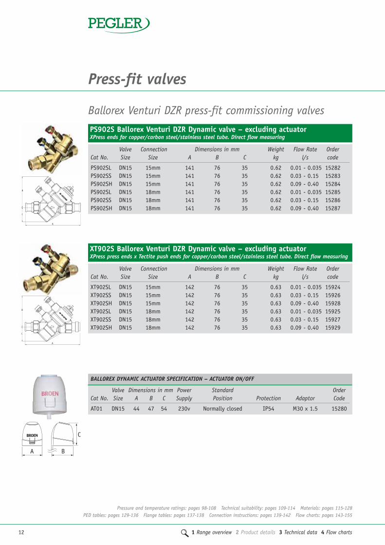
Press-fit valves
PS902S Ballorex Venturi DZR Dynamic valve – excluding actuatorXPress ends for copper/carbon steel/stainless steel tube. Direct flow measuring
Valve Connection Dimensions in mm Weight Flow Rate OrderCat No. Size Size A B C kg l/s code
PS902SL DN15 15mm 141 76 35 0.62 0.01 - 0.035 15282PS902SS DN15 15mm 141 76 35 0.62 0.03 - 0.15 15283PS902SH DN15 15mm 141 76 35 0.62 0.09 - 0.40 15284PS902SL DN15 18mm 141 76 35 0.62 0.01 - 0.035 15285PS902SS DN15 18mm 141 76 35 0.62 0.03 - 0.15 15286PS902SH DN15 18mm 141 76 35 0.62 0.09 - 0.40 15287
Ballorex Venturi DZR press-fit commissioning valves
B
C
A
XT902S Ballorex Venturi DZR Dynamic valve – excluding actuatorXPress press ends x Tectite push ends for copper/carbon steel/stainless steel tube. Direct flow measuring
Valve Connection Dimensions in mm Weight Flow Rate OrderCat No. Size Size A B C kg l/s code
XT902SL DN15 15mm 142 76 35 0.63 0.01 - 0.035 15924XT902SS DN15 15mm 142 76 35 0.63 0.03 - 0.15 15926XT902SH DN15 15mm 142 76 35 0.63 0.09 - 0.40 15928XT902SL DN15 18mm 142 76 35 0.63 0.01 - 0.035 15925XT902SS DN15 18mm 142 76 35 0.63 0.03 - 0.15 15927XT902SH DN15 18mm 142 76 35 0.63 0.09 - 0.40 15929
B
C
A
Valve Dimensions in mm Power Standard OrderCat No. Size A B C Supply Position Protection Adaptor Code
AT01 DN15 44 47 54 230v Normally closed IP54 M30 x 1.5 15280
BALLOREX DYNAMIC ACTUATOR SPECIFICATION – ACTUATOR ON/OFF
A B
C
Pressure and temperature ratings: pages 98-108 Technical suitability: pages 109-114 Materials: pages 115-128PED tables: pages 129-136 Flange tables: pages 137-138 Connection instructions: pages 139-142 Flow charts: pages 143-155

1 Range overview 2 Product details 3 Technical data 4 Flow charts 13
22
PS900S Ballorex Venturi DZR Static commissioning station (FODRV)With regulation, isolation and flow measurement functions. XPress ends for copper/carbon steel/stainless steel tube
Valve Connection Dimensions in mm Weight Kvs Kv Loss OrderCat No. Size Size A B C D kg m3/h m3/h Factor code
PS900SL DN15 15mm 138 75 162 76 0.49 0.359 0.629 0.33 15550PS900SS DN15 15mm 138 75 162 76 0.49 0.749 1.620 0.21 15551PS900SH DN15 15mm 138 75 162 76 0.49 1.560 2.490 0.39 15552PS900SL DN15 18mm 138 75 162 76 0.49 0.359 0.629 0.33 15553PS900SS DN15 18mm 138 75 162 76 0.49 0.749 1.620 0.21 15554PS900SH DN15 18mm 138 75 162 76 0.49 1.560 2.490 0.39 15555PS900SL DN20 15mm 143 75 166 79 0.51 0.746 1.430 0.27 15556PS900SS DN20 15mm 143 75 166 79 0.51 1.560 2.820 0.31 15557PS900SH DN20 15mm 143 75 166 79 0.51 2.950 5.720 0.27 15558PS900SL DN20 18mm 143 75 166 79 0.51 0.746 1.430 0.27 15559PS900SS DN20 18mm 143 75 166 79 0.51 1.560 2.820 0.31 15560PS900SH DN20 18mm 143 75 166 79 0.51 2.950 5.720 0.27 15561PS900SL DN20 22mm 147 75 166 79 0.52 0.746 1.430 0.27 15562PS900SS DN20 22mm 147 75 166 79 0.52 1.560 2.820 0.31 15563PS900SH DN20 22mm 147 75 166 79 0.52 2.950 5.720 0.27 15564PS900SS DN25 28mm 165 75 177 83 0.88 2.950 7.540 0.15 15565PS900SH DN25 28mm 165 75 177 83 0.88 6.010 12.10 0.25 15566PS900SH DN32 35mm 188 122 237 109 1.62 6.010 13.200 0.21 15567PS900SH DN40 42mm 194 122 240 113 2.18 9.200 22.000 0.17 15568PS900SH DN50 54mm 243 122 265 120 3.38 17.100 36.000 0.23 15569
Valve Dimensions in mm Power Control Voltage Standard OrderCat No. Size A B C Supply Input Position Protection Adaptor Code
AE01 DN15 64 44 55 24v AC 0-10v DC Normally closed IP54 M30 x 1.5 15281
BALLOREX DYNAMIC ACTUATOR SPECIFICATION – ACTUATOR MODULATING
A B
C
Pressure and temperature ratings: pages 98-108 Technical suitability: pages 109-114 Materials: pages 115-128PED tables: pages 129-136 Flange tables: pages 137-138 Connection instructions: pages 139-142 Flow charts: pages 143-155

14 1 Range overview 2 Product details 3 Technical data 4 Flow charts
Press-fit valves
PS901S Ballorex Venturi DZR double regulating valve (DRV)With regulation and isolation functions. XPress ends for copper/carbon steel/stainless steel tube
Valve Connection Dimensions in mm Weight Kv OrderCat No. Size Size A B C D kg m3/h code
PS901SL DN15 15mm 101 75 126 76 0.31 1.62 15570PS901SS DN15 15mm 101 75 126 76 0.31 2.10 15571PS901SL DN15 18mm 101 75 126 76 0.31 1.62 15572PS901SS DN15 18mm 101 75 126 76 0.32 2.10 15573PS901SL DN20 15mm 105 75 128 79 0.39 4.26 15574PS901SS DN20 15mm 105 75 128 79 0.39 4.79 15575PS901SL DN20 18mm 105 75 128 79 0.39 4.26 15576PS901SS DN20 18mm 105 75 128 79 0.39 4.79 15577PS901SL DN20 22mm 109 75 128 79 0.40 4.26 15578PS901SS DN20 22mm 109 75 128 79 0.40 4.79 15579PS901SS DN25 28mm 128 75 140 83 0.68 12.80 15580PS901SS DN32 35mm 146 122 195 109 1.35 13.28 15581PS901SS DN40 42mm 170 122 198 113 1.77 23.30 15582PS901SS DN50 54mm 202 122 198 113 2.81 35.30 15583
XT900S Ballorex Venturi DZR Static commissioning station (FODRV)With regulation, isolation and flow measurement functions. XPress press ends x Tectite push ends for copper/carbon steel/stainless steel tube
Valve Connection Dimensions in mm Weight Kvs Kv Loss OrderCat No. Size Size A B C D kg m3/h m3/h Factor code
XT900SL DN15 15mm 141 75 162 76 0.49 0.359 0.629 0.33 15620XT900SS DN15 15mm 141 75 162 76 0.49 0.749 1.620 0.21 15621XT900SH DN15 15mm 141 75 162 76 0.49 1.560 2.490 0.39 15622XT900SL DN15 18mm 142 75 163 76 0.49 0.359 0.629 0.33 15623XT900SS DN15 18mm 142 75 163 76 0.49 0.749 1.620 0.21 15624XT900SH DN15 18mm 142 75 163 76 0.49 1.560 2.490 0.39 15625XT900SL DN20 15mm 147 75 161 79 0.52 0.746 1.430 0.27 15626XT900SS DN20 15mm 147 75 161 79 0.52 1.560 2.820 0.31 15627XT900SH DN20 15mm 147 75 161 79 0.52 2.950 5.720 0.27 15628XT900SL DN20 18mm 148 75 166 79 0.52 0.746 1.430 0.27 15629XT900SS DN20 18mm 148 75 166 79 0.52 1.560 2.820 0.31 15630XT900SH DN20 18mm 148 75 166 79 0.52 2.950 5.720 0.27 15631XT900SL DN20 22mm 153 75 167 79 0.53 0.746 1.430 0.27 15632XT900SS DN20 22mm 153 75 167 79 0.53 1.560 2.820 0.31 15633XT900SH DN20 22mm 153 75 167 79 0.53 2.950 5.720 0.27 15634XT900SS DN25 28mm 171 75 177 83 0.88 2.950 7.540 0.15 15635XT900SH DN25 28mm 171 75 177 83 0.88 6.010 12.10 0.25 15636XT900SH DN32 35mm 219 122 237 109 1.71 6.010 13.200 0.21 15637XT900SH DN40 42mm 239 122 249 113 2.25 9.200 22.000 0.17 15638XT900SH DN50 54mm 256 122 264 120 3.37 17.100 36.000 0.23 15639
Pressure and temperature ratings: pages 98-108 Technical suitability: pages 109-114 Materials: pages 115-128PED tables: pages 129-136 Flange tables: pages 137-138 Connection instructions: pages 139-142 Flow charts: pages 143-155

1 Range overview 2 Product details 3 Technical data 4 Flow charts 15
2XT901S Ballorex Venturi DZR double regulating valve (DRV)With regulation and isolation functions.XPress press ends x Tectite push ends for copper/carbon steel/stainless steel tube
Valve Connection Dimensions in mm Weight Kv OrderCat No. Size Size A B C D kg m3/h code
XT901SL DN15 15mm 104 75 126 76 0.30 1.62 15910XT901SS DN15 15mm 104 75 126 76 0.30 2.10 15911XT901SL DN15 18mm 105 75 127 76 0.31 1.62 15912XT901SS DN15 18mm 105 75 127 76 0.31 2.10 15913XT901SL DN20 15mm 109 75 127 79 0.40 4.26 15914XT901SS DN20 15mm 109 75 127 79 0.40 4.79 15915XT901SL DN20 18mm 110 75 128 79 0.40 4.26 15916XT901SS DN20 18mm 110 75 128 79 0.40 4.79 15917XT901SL DN20 22mm 115 75 129 79 0.41 4.26 15918XT901SS DN20 22mm 115 75 129 79 0.41 4.79 15919XT901SS DN25 28mm 134 75 140 83 0.68 12.80 15920XT901SS DN32 35mm 177 122 195 109 1.45 13.28 15921XT901SS DN40 42mm 197 122 207 113 1.83 23.30 15922XT901SS DN50 54mm 225 122 223 120 2.81 35.30 15923
Pressure and temperature ratings: pages 98-108 Technical suitability: pages 109-114 Materials: pages 115-128PED tables: pages 129-136 Flange tables: pages 137-138 Connection instructions: pages 139-142 Flow charts: pages 143-155

16 1 Range overview 2 Product details 3 Technical data 4 Flow charts
Press-fit valves
Ballorex Venturi accessories
A
C
B
Insulation jackets for Ballorex Venturi valve
Size A B C Order code1/2" 92 112 70 152503/4" 98 118 75 152511" 110 124 80 1525211/4" 128 133 94 1525311/2" 138 140 100 152542" 153 152 118 15255
DZR Red and blue self seal test pointsMale taper connection
Size A B Weight kg Order code1/4" x 36mm 14 36 0.03 1260411/4" x 75mm 14 75 0.06 126042
910TP Red and blue Venturi test pointsMale taper thread
Size A B Weight kg Order code1/4" 14 38 0.03 15201
920EX Venturi test point extension kitMale taper thread
Size A B Weight kg Order code1/4" x 50mm 17 65 0.09 15205
A
B
B
A
A
B
Pressure and temperature ratings: pages 98-108 Technical suitability: pages 109-114 Materials: pages 115-128PED tables: pages 129-136 Flange tables: pages 137-138 Connection instructions: pages 139-142 Flow charts: pages 143-155

1 Range overview 2 Product details 3 Technical data 4 Flow charts 17
2DZR press-fit commissioning valves
PS1200 Double regulating valve (DRV)DZR brass body, XPress ends for copper/carbon steel/stainless steel tube
Size A B Weight kg Kv m3/h Order code
15mm standard flow 127 106 0.56 0.40 12600918mm standard flow 127 106 0.58 2.30 12613122mm standard flow 136 106 0.64 2.48 12601028mm standard flow 157 113 1.00 7.15 12601135mm standard flow 181 120 1.48 15.08 12601242mm standard flow 195 123 1.89 20.84 12601354mm standard flow 235 138 3.29 28.89 126014
A
B
XT1200 Double regulating valve (DRV)DZR brass body, XPress press end x Tectite push end for copper/carbon steel/stainless steel tube
Size A B Weight kg Kv m3/h Order code
15mm standard flow 126 106 0.56 0.40 12620918mm standard flow 127 106 0.56 2.30 12621022mm standard flow 139 106 0.65 2.48 12621128mm standard flow 162 113 1.00 7.15 12621235mm standard flow 210 120 1.61 15.08 12621342mm standard flow 226 123 2.12 20.84 12621454mm standard flow 267 138 3.54 28.89 126215
A
B
A
B
PS1260 Commissioning valve (FODRV)DZR brass body with test points, XPress ends for copper/carbon steel/stainless steel tube
Size A B Weight kg Kv m3/h Kvs m3/h Order code
15mm low flow 127 106 0.61 0.40 0.41 12602915mm standard flow 127 106 0.60 1.86 2.15 12603018mm low flow 127 106 0.61 0.40 0.41 12613418mm standard flow 127 106 0.60 1.86 2.15 12613522mm standard flow 136 106 0.68 2.27 4.78 12603128mm standard flow 157 113 1.04 6.11 8.11 12603235mm standard flow 181 120 1.50 12.65 15.41 12603342mm standard flow 195 123 1.96 19.00 22.23 12603454mm standard flow 235 138 3.36 28.42 48.21 126035
Pressure and temperature ratings: pages 98-108 Technical suitability: pages 109-114 Materials: pages 115-128PED tables: pages 129-136 Flange tables: pages 137-138 Connection instructions: pages 139-142 Flow charts: pages 143-155

18 1 Range overview 2 Product details 3 Technical data 4 Flow charts
Press-fit valves
DZR press-fit metering stationsPS1250 DZR metering stationDZR brass body with test points, XPress ends for copper/carbon steel/stainless steel tube
Size A B Weight kg Kvs m3/h Order code
15mm low flow 96 40 0.29 0.41 12607015mm standard flow 96 40 0.29 2.15 12607118mm low flow 96 40 0.29 0.41 12613218mm standard flow 96 40 0.29 2.15 12613322mm standard flow 101 42 0.34 4.78 12607228mm standard flow 117 46 0.54 8.11 12607335mm standard flow 127 52 0.76 15.41 12607442mm standard flow 139 52 0.89 22.23 12607554mm standard flow 153 57 1.32 48.21 126076
A
B
XT1250 DZR metering stationDZR brass body with test points, XPress press end x Tectite push end for copper/carbon steel/stainless steel tube
Size A B Weight kg Kvs m3/h Order code
15mm low flow 95 65 0.33 0.41 12621615mm standard flow 95 65 0.33 2.15 12621718mm low flow 96 65 0.33 0.41 12621818mm standard flow 96 65 0.33 2.15 12621922mm standard flow 104 68 0.40 4.78 12622028mm standard flow 122 78 0.60 8.11 12622135mm standard flow 156 83 0.98 15.41 12622242mm standard flow 170 89 1.18 22.23 12622354mm standard flow 185 103 1.64 48.21 126224
A
B
A
B
XT1260 Commissioning valve (FODRV)DZR brass body with test points, XPress press end x Tectite push end for copper/carbon steel/stainless steel tube
Size A B Weight kg Kv m3/h Kvs m3/h Order code
15mm low flow 126 106 0.61 0.40 0.41 12620015mm standard flow 126 106 0.61 1.86 2.15 12620118mm low flow 127 106 0.60 0.40 0.41 12620218mm standard flow 127 106 0.60 1.86 2.15 12620322mm standard flow 139 106 0.69 2.27 4.78 12620428mm standard flow 162 113 1.05 6.11 8.11 12620535mm standard flow 210 120 1.67 12.65 15.41 12620642mm standard flow 226 123 2.18 19.00 22.23 12620754mm standard flow 267 138 3.61 28.42 48.21 126208
Pressure and temperature ratings: pages 98-108 Technical suitability: pages 109-114 Materials: pages 115-128PED tables: pages 129-136 Flange tables: pages 137-138 Connection instructions: pages 139-142 Flow charts: pages 143-155
Temperature range: -10ºC to +110ºC
Temperature range: -10ºC to +110ºC
Temperature range: -10ºC to +110ºC

1 Range overview 2 Product details 3 Technical data 4 Flow charts 19
2
Size Connection A B Weight kg Kv m3/h Order code
DN15 15mm 98 85 0.39 14.00 103301DN15 18mm 98 85 0.39 14.00 103302DN20 22mm 104 95 0.56 32.00 103303DN25 28mm 117 110 0.84 57.00 103304DN32 35mm 130 125 1.26 90.00 103305DN40 42mm 141 145 1.69 129.00 103306DN50 54mm 165 170 2.67 230.00 103307
PS1070/125 Bronze full way gate valveXPress ends for copper/carbon steel/stainless steel tube
A
B
A
B
Size Connection A B Weight kg Kv m3/h Order code
DN15 15mm 97.5 75 0.39 14.00 103311DN15 18mm 103.5 85 0.39 14.00 103312DN20 22mm 103.5 85 0.56 32.00 103313DN25 28mm 116.5 100 0.84 57.00 103314DN32 35mm 129.5 110 1.26 90.00 103315DN40 42mm 140.5 130 1.69 129.00 103316DN54 54mm 164.5 155 2.67 230.00 103317
PS1070/125LS Bronze full way gate valve with lockshieldXPress ends for copper/carbon steel/stainless steel tube
A
B
Size Connection A B Weight kg Kv m3/h Order code
DN15 15mm 97.5 85 0.38 14.00 204056DN15 18mm 103.5 95 0.38 14.00 204057DN20 22mm 103.5 95 0.56 32.00 204058DN25 28mm 116.5 110 0.87 57.00 204059DN32 35mm 129.5 125 1.30 90.00 204060DN40 42mm 140.5 145 1.62 129.00 204061DN50 54mm 164.5 170 2.84 230.00 204062
PS1078 DZR full way gate valveXPress ends for copper/carbon steel/stainless steel tube
Bronze press-fit gate valves
Pressure and temperature ratings: pages 98-108 Technical suitability: pages 109-114 Materials: pages 115-128PED tables: pages 129-136 Flange tables: pages 137-138 Connection instructions: pages 139-142 Flow charts: pages 143-155
Temperature range: -10ºC to +110ºC
Temperature range: -10ºC to +110ºC
Temperature range: -10ºC to +110ºC

20 1 Range overview 2 Product details 3 Technical data 4 Flow charts
Size Connection A B Weight kg Kv m3/h Order code
DN15 15mm 97.5 75 0.38 14.00 204063DN15 18mm 103.5 85 0.38 14.00 204064DN20 22mm 103.5 85 0.56 32.00 204065DN25 28mm 116.5 100 0.87 57.00 204066DN30 35mm 129.5 110 1.30 90.00 204067DN40 42mm 140.5 130 1.62 129.00 204068DN50 54mm 164.5 155 2.84 230.00 204069
PS1078LS DZR full way gate valve with lockshieldXPress ends for copper/carbon steel/stainless steel tube
Size Connection A B Weight kg Kv m3/h Order code
DN15 15mm 98 85 0.38 14.00 203301DN15 18mm 98 85 0.38 14.00 203302DN20 22mm 104 95 0.56 32.00 203303DN25 28mm 117 110 0.87 57.00 203304DN32 35mm 130 125 1.30 90.00 203305DN40 42mm 141 145 1.62 129.00 203306DN50 54mm 165 170 2.84 230.00 203307
PS1068 Brass full way gate valveXPress ends for copper/carbon steel/stainless steel tube
A
B
Size Connection A B Weight kg Kv m3/h Order code
DN15 15mm 99 85 0.39 14.00 203320DN15 18mm 100 85 0.39 14.00 203321DN20 22mm 109 95 0.56 32.00 203322DN25 28mm 124 110 0.85 57.00 203323DN32 35mm 162 125 1.41 90.00 203324DN40 42mm 175 145 1.90 129.00 203325DN50 54mm 200 170 2.92 230.00 203326
XT1068 Brass full way gate valveXPress press ends x Tectite push ends for copper/carbon steel/stainless steel tube
A
B
Brass press-fit gate valves
B
A
Press-fit valves
Pressure and temperature ratings: pages 98-108 Technical suitability: pages 109-114 Materials: pages 115-128PED tables: pages 129-136 Flange tables: pages 137-138 Connection instructions: pages 139-142 Flow charts: pages 143-155
Temperature range: -10ºC to +110ºC
Temperature range: -10ºC to +110ºC
Temperature range: 15mm to 28mm -10ºC to +110ºC35mm to 54mm -10ºC to +90ºC

1 Range overview 2 Product details 3 Technical data 4 Flow charts 21
2
Size Connection A B Weight kg Kv m3/h Order code
DN15 15mm 98 85 0.38 14.00 203311DN15 18mm 98 85 0.38 14.00 203312DN20 22mm 104 95 0.56 32.00 203313DN25 28mm 117 110 0.87 57.00 203314DN32 35mm 130 125 1.30 90.00 203315DN40 42mm 141 145 1.62 129.00 203316DN50 54mm 165 170 2.84 230.00 203317
PS1068LS Brass full way gate valve with lockshieldXPress ends for copper/carbon steel/stainless steel tube
B
A
Size Connection A B Weight kg Kv m3/h Order code
DN15 15mm 99 85 0.39 14.00 203327DN15 18mm 100 85 0.39 14.00 203328DN20 22mm 109 95 0.56 32.00 203329DN25 28mm 124 110 0.85 57.00 203330DN32 35mm 162 125 1.41 90.00 203331DN40 42mm 175 145 1.90 129.00 203332DN50 54mm 200 170 2.92 230.00 203333
XT1068LS Brass full way gate valve with lockshieldXPress press ends x Tectite push ends for copper/carbon steel/stainless steel tube
B
A
Size Connection A B Weight kg Kv m3/h Order code
DN15 15mm 105 39 0.30 17.00 242301DN15 18mm 105 39 0.31 17.00 242302DN20 22mm 115 50 0.50 41.00 242303DN25 28mm 131 55 0.75 70.00 242304DN32 35mm 152 62 1.17 121.00 242305DN40 42mm 165 78 1.85 200.00 242306DN50 54mm 197 84 3.00 292.00 242307
PS500 Brass chrome plated ball valve with lever, full boreXPress ends for copper/carbon steel/stainless steel tube
A
B
DZR Brass press-fit ball valves
Pressure and temperature ratings: pages 98-108 Technical suitability: pages 109-114 Materials: pages 115-128PED tables: pages 129-136 Flange tables: pages 137-138 Connection instructions: pages 139-142 Flow charts: pages 143-155
Temperature range: -10ºC to +110ºC
Temperature range: -10ºC to +110ºC
Temperature range: 15mm to 28mm -10ºC to +110ºC35mm to 54mm -10ºC to +90ºC

22 1 Range overview 2 Product details 3 Technical data 4 Flow charts
Size Connection A B Weight kg Kv m3/h Order code
DN15 15mm 105 40 0.30 17.00 243301DN15 18mm 105 40 0.31 17.00 243302DN20 22mm 115 51 0.50 41.00 243303DN25 28mm 131 55 0.75 70.00 243304
PS500T Brass chrome plated ball valve with tee, full boreXPress ends for copper/carbon steel/stainless steel tube
Size Connection A B Weight kg Kv m3/h Order code
DN15 15mm 105 39 0.30 17.00 245220DN15 18mm 105 39 0.31 17.00 245221DN20 22mm 115 50 0.50 41.00 245222DN25 28mm 131 55 0.75 70.00 245223DN32 35mm 152 62 1.17 121.00 245224DN40 42mm 165 78 1.85 200.00 245225DN50 54mm 197 84 3.00 292.00 245226
PS550 DZR ball valve with lever, full boreXPress ends for copper/carbon steel/stainless steel tube
A
B
Size Connection A B Weight kg Kv m3/h Order code
DN15 15mm 105 40 0.30 17.00 245230DN15 18mm 105 40 0.31 17.00 245231DN20 22mm 115 51 0.50 41.00 245232DN25 28mm 131 55 0.75 70.00 245233
PS550T DZR ball valve with tee, full boreXPress ends for copper/carbon steel/stainless steel tube
B
A
Press-fit valves
B
A
Size Connection A B Weight kg Kv m3/h Order code
DN15 15mm 106 39 0.22 17.00 243320DN15 18mm 107 39 0.22 17.00 243321DN20 22mm 121 51 0.33 41.00 243322DN25 28mm 139 55 0.56 70.00 243323DN32 35mm 184 62 0.99 121.00 243324DN40 42mm 199 78 1.45 200.00 243325DN50 54mm 234 84 2.82 292.00 243326
XT500 Brass chrome plated ball valve with lever, full boreXPress press ends x Tectite push fit for copper/carbon steel/stainless steel tube
A
B
Pressure and temperature ratings: pages 98-108 Technical suitability: pages 109-114 Materials: pages 115-128PED tables: pages 129-136 Flange tables: pages 137-138 Connection instructions: pages 139-142 Flow charts: pages 143-155
Temperature range: -10ºC to +110ºC
Temperature range: -10ºC to +110ºC
Temperature range: -10ºC to +110ºC
Temperature range: 15mm to 28mm -10ºC to +110ºC35mm to 54mm -10ºC to +90ºC

1 Range overview 2 Product details 3 Technical data 4 Flow charts 23
2
Size Connection A B Weight kg Kv m3/h Order code
DN15 15mm 106 39 0.30 17.00 245120DN15 18mm 107 39 0.30 17.00 245121DN20 22mm 121 50 0.50 41.00 245122DN25 28mm 139 55 0.76 70.00 245123DN32 35mm 184 62 1.33 121.00 245124DN40 42mm 199 78 1.84 200.00 245125DN50 54mm 234 84 2.82 292.00 245126
XT550 DZR ball valve with lever, full boreXPress press ends x Tectite push ends for copper/carbon steel/stainless steel tube
A
B
Size Connection A B Weight kg Kv m3/h Order code
DN15 15mm 106 78.3 0.37 17.00 245273DN15 18mm 107 78.3 0.58 17.00 245274DN20 22mm 121 97 0.61 41.00 245275DN25 28mm 139 101 0.86 70.00 245276DN32 35mm 184 108 1.42 121.00 245277DN40 42mm 199 128 2.00 200.00 245278DN50 54mm 234 146.2 3.08 292.00 245279
XT550EL DZR ball valve with extended lever, full boreXPress press ends x Tectite push ends for copper/carbon steel/stainless steel tube
A
B
Size Connection A B Weight kg Kv m3/h Order code
DN15 15mm 105 78.3 0.372 17.00 245300DN15 18mm 105 78.3 0.374 17.00 245301DN20 22mm 115 97 0.598 41.00 245302DN25 28mm 131 101 0.72 70.00 245303DN32 35mm 152 108 1.25 121.00 245304DN40 42mm 165 128 1.77 200.00 245305DN50 54mm 197 146.2 2.81 292.00 245306
PS550EL DZR ball valve with extended lever, full boreXPress press ends x Tectite push ends for copper/carbon steel/stainless steel tube
A
B
Pressure and temperature ratings: pages 98-108 Technical suitability: pages 109-114 Materials: pages 115-128PED tables: pages 129-136 Flange tables: pages 137-138 Connection instructions: pages 139-142 Flow charts: pages 143-155
Temperature range: -10ºC to +110ºC
Temperature range: 15mm to 28mm -10ºC to +110ºC35mm to 54mm -10ºC to +90ºC
Temperature range: 15mm to 28mm -10ºC to +110ºC35mm to 54mm -10ºC to +90ºC

24 1 Range overview 2 Product details 3 Technical data 4 Flow charts
Press-fit valves
Locking device (for standard lever handle products)
Pattern No. Suitable for Order code
LD1 1/4", 3/8", 1/2" 258001LD2 3/4", 1", 11/4" 258002LD3 11/2", 2" 258003
Padlock and key
Pattern No. Suitable for Order code
PDK3 1/4", 3/8", 1/2", 3/4", 1", 11/4" 258011PDK4 11/2", 2" 258012
PBSEK Stem extension kits (suitable for PB500 ranges)
Pattern No. Suitable for Order code
PBSEK7 1/4", 3/8", 1/2", 15mm 227027PBSEK8 3/4", 1", 11/4", 22mm, 28mm, 35mm 227028PBSEK9 11/2", 2", 42mm, 54mm 227029PBSEK10 21/2" 227030PBSEK11 3", 4" 227031
Ball valve accessories
Pressure and temperature ratings: pages 98-108 Technical suitability: pages 109-114 Materials: pages 115-128PED tables: pages 129-136 Flange tables: pages 137-138 Connection instructions: pages 139-142 Flow charts: pages 143-155

1 Range overview 2 Product details 3 Technical data 4 Flow charts 25
2
Size Connection A B Weight kg Flow l/s Kv m3/h Order code
DN15 15mm 108 45 0.45 0.04 1.80 1223010.10 3.700.20 5.100.40 5.70
DN15 18mm 108 45 0.45 0.04 1.80 1223020.10 3.700.20 5.100.40 5.70
DN20 22mm 124 55 0.68 0.04 2.70 1223030.10 5.500.40 13.601.00 15.30
DN25 28mm 135 60 1.01 0.01 7.70 1223040.20 13.900.30 18.401.00 25.30
DN32 35mm 151 65 1.49 0.20 15.00 1223050.30 26.600.40 25.301.00 32.60
DN40 42mm 170 75 1.95 0.40 30.30 1223060.60 40.200.80 48.503.00 54.40
DN50 54mm 200 90 3.05 0.60 42.00 1223070.80 54.001.50 86.204.00 98.00
PS1060A Press-fit swing check valveXPress ends for copper/carbon steel/stainless steel tube
Bronze press-fit check valves
B
A
Pressure and temperature ratings: pages 98-108 Technical suitability: pages 109-114 Materials: pages 115-128PED tables: pages 129-136 Flange tables: pages 137-138 Connection instructions: pages 139-142 Flow charts: pages 143-155
Temperature range: -10ºC to +110ºC

26 1 Range overview 2 Product details 3 Technical data 4 Flow charts
Press-fit valves
Ballofix DZR isolating ball valves
Size Pattern No A Weight kg Order code
15mm 4381ZA 83 0.16 1306022mm 4481ZA 88 0.20 13061
Ballofix Isolating ball valve – straight patternXPress ends for copper/carbon steel/stainless steel tube. Screw driver slot
Size Pattern No A Weight kg Order code
15mm 4381ZP 83 0.17 13062
Ballofix Isolating ball valve – straight patternXPress ends for copper/carbon steel/stainless steel tube. Black plastic handle
B
A
B
A
Size Connection A B Weight kg Order code
DN15 15mm 89.5 44 0.30 15472DN15 18mm 94.5 47 0.30 15473DN20 22mm 94.5 47 0.41 15474DN25 28mm 109.5 58 0.59 15475DN32 35mm 124.5 68 0.96 15476DN40 42mm 142.5 78 1.19 15477DN50 54mm 172.5 98 2.00 15478
PS913 Bronze Y pattern strainerXPress ends for copper/carbon steel/stainless steel tube
Bronze press-fit strainers
B
A
Size A B Weight kg Order code
15mm 116 58 0.43 1543018mm 116 58 0.43 1543122mm 128 75 0.63 1543228mm 152 88 0.99 1543335mm 177 108 1.55 1543442mm 195 124 1.94 1543554mm 235 161 3.50 15436
PS954 Bronze Y strainerXPress ends for copper/carbon steel/stainless steel tube
B
A
Pressure and temperature ratings: pages 98-108 Technical suitability: pages 109-114 Materials: pages 115-128PED tables: pages 129-136 Flange tables: pages 137-138 Connection instructions: pages 139-142 Flow charts: pages 143-155
Temperature range: -10ºC to +110ºC
Temperature range: 15mm to 28mm -10ºC to +110ºC35mm to 54mm -10ºC to +90ºC

1 Range overview 2 Product details 3 Technical data 4 Flow charts 27
Small plastic handle – with hexagon spigot
Order code
CPT0059 Black 13712
Large plastic handle – with hexagon spigot
Order code
CPT0073 Black 13721
Ballofix accessories
Small plastic handle – with screw
Order code
ERG Black 13724ERG Red 13728ERG Blue 13729ERG Chrome 13732
Large plastic handle – with screw
Order code
ERG Black 13725
Pressure and temperature ratings: pages 98-108 Technical suitability: pages 109-114 Materials: pages 115-128PED tables: pages 129-136 Flange tables: pages 137-138 Connection instructions: pages 139-142 Flow charts: pages 143-155

28 1 Range overview 2 Product details 3 Technical data 4 Flow charts
Push-fit valves
PT902S Ballorex Venturi DZR Dynamic valve – excluding actuatorTectite ends for copper/carbon steel/stainless steel tube. Direct flow measuring
Valve Connection Dimensions in mm Weight Flow Rate OrderCat No. Size Size A B C kg l/s code
PT902SL DN15 15mm 144 76 35 0.62 0.01 - 0.035 15288PT902SS DN15 15mm 144 76 35 0.62 0.03 - 0.15 15289PT902SH DN15 15mm 144 76 35 0.62 0.09 - 0.40 15290PT902SL DN15 18mm 144 76 35 0.62 0.01 - 0.035 15291PT902SS DN15 18mm 144 76 35 0.62 0.03 - 0.15 15292PT902SH DN15 18mm 144 76 35 0.62 0.09 - 0.40 15293
Ballorex Venturi DZR push-fit commissioning valves
B
C
A
Valve Dimensions in mm Power Standard OrderCat No. Size A B C Supply Position Protection Adaptor Code
AT01 DN15 44 47 54 230v Normally closed IP54 M30 x 1.5 15280
BALLOREX DYNAMIC ACTUATOR SPECIFICATION – ACTUATOR ON/OFF
A B
C
Valve Dimensions in mm Power Control Voltage Standard OrderCat No. Size A B C Supply Input Position Protection Adaptor Code
AE01 DN15 64 44 55 24v AC 0-10v DC Normally closed IP54 M30 x 1.5 15281
BALLOREX DYNAMIC ACTUATOR SPECIFICATION – ACTUATOR MODULATING
A B
C
Pressure and temperature ratings: pages 98-108 Technical suitability: pages 109-114 Materials: pages 115-128PED tables: pages 129-136 Flange tables: pages 137-138 Connection instructions: pages 139-142 Flow charts: pages 143-155

1 Range overview 2 Product details 3 Technical data 4 Flow charts 29
2Ballorex Venturi DZR push-fit commissioning valves
Valve Connection Dimensions in mm Weight Kvs Kv Loss OrderCat No. Size Size A B C D kg m3/h m3/h Factor code
PT900SL DN15 15mm 143 75 162 76 0.48 0.359 0.629 0.33 15584PT900SS DN15 15mm 143 75 162 76 0.48 0.749 1.620 0.21 15585PT900SH DN15 15mm 143 75 162 76 0.48 1.560 2.490 0.39 15586PT900SL DN15 18mm 143 75 162 76 0.48 0.359 0.629 0.33 15587PT900SS DN15 18mm 143 75 162 76 0.48 0.749 1.620 0.21 15588PT900SH DN15 18mm 143 75 162 76 0.48 1.560 2.490 0.39 15589PT900SL DN20 15mm 143 75 166 79 0.52 0.746 1.430 0.27 15590PT900SS DN20 15mm 143 75 166 79 0.52 1.560 2.820 0.31 15591PT900SH DN20 15mm 143 75 166 79 0.52 2.950 5.720 0.27 15592PT900SL DN20 18mm 143 75 166 79 0.52 0.746 1.430 0.27 15593PT900SS DN20 18mm 143 75 166 79 0.52 1.560 2.820 0.31 15594PT900SH DN20 18mm 143 75 166 79 0.52 2.950 5.720 0.27 15595PT900SL DN20 22mm 149 75 166 79 0.52 0.746 1.430 0.27 15596PT900SS DN20 22mm 149 75 166 79 0.52 1.560 2.820 0.31 15597PT900SH DN20 22mm 149 75 166 79 0.52 2.950 5.720 0.27 15598PT900SS DN25 28mm 179 75 177 83 0.85 2.950 7.540 0.15 15599PT900SH DN25 28mm 179 75 177 83 0.85 6.010 12.100 0.25 15600PT900SH DN32 35mm 229 122 237 109 1.78 6.010 13.200 0.21 15601PT900SH DN40 42mm 251 122 240 113 2.40 9.200 22.000 0.17 15602PT900SH DN50 54mm 280 122 265 120 3.26 17.100 36.000 0.23 15603
PT900S Ballorex Venturi DZR static commissioning valve (FODRV)Tectite push-fit ends for copper, carbon and stainless steel tube
PT901S Ballorex Venturi DZR double regulating valve (DRV)Tectite push-fit ends for copper, carbon and stainless steel tube
Valve Connection Dimensions in mm Weight Kv OrderCat No. Size Size A B C D kg m3/h code
PT901SL DN15 15mm 106 75 126 76 0.30 1.62 15604PT901SS DN15 15mm 106 75 126 76 0.30 2.10 15605PT901SL DN15 18mm 106 75 126 76 0.30 1.62 15606PT901SS DN15 18mm 106 75 126 76 0.30 2.10 15607PT901SL DN20 15mm 121 75 128 79 0.40 4.26 15608PT901SS DN20 15mm 121 75 128 79 0.40 4.79 15609PT901SL DN20 18mm 121 75 128 79 0.40 4.26 15610PT901SS DN20 18mm 121 75 128 79 0.40 4.79 15611PT901SL DN20 22mm 121 75 128 79 0.40 4.26 15612PT901SS DN20 22mm 121 75 128 79 0.40 4.79 15613PT901SS DN25 28mm 142 75 140 83 0.65 12.80 15614PT901SS DN32 35mm 187 122 195 109 1.52 13.28 15615PT901SS DN40 42mm 209 122 198 113 1.98 23.30 15616PT901SS DN50 54mm 239 122 198 113 2.69 35.30 15617
AC
D
B
Pressure and temperature ratings: pages 98-108 Technical suitability: pages 109-114 Materials: pages 115-128PED tables: pages 129-136 Flange tables: pages 137-138 Connection instructions: pages 139-142 Flow charts: pages 143-155

30 1 Range overview 2 Product details 3 Technical data 4 Flow charts
Push-fit valves
DZR push-fit metering stations
PT1250 DZR metering stationComplete with DZR test points, dual seal, XPress ends for copper, carbon and stainless steel tube
Size A B Weight kg Kv m3/h Order code
DN15/18mm low flow 96 40 0.33 0.41 126136DN15/18mm standard flow 96 40 0.33 2.15 126137DN15/15mm low flow 97 40 0.33 0.41 126060DN15/15mm standard flow 97 40 0.33 2.15 126061DN20/22mm standard flow 119 42 0.36 4.78 126062DN25/28mm standard flow 138 46 0.50 8.11 126063DN32/35mm standard flow 169 52 1.00 15.41 126064DN40/42mm standard flow 182 52 1.25 22.23 126065DN50/54mm standard flow 199 57 1.91 48.21 126066
A
B
Pressure and temperature ratings: pages 98-108 Technical suitability: pages 109-114 Materials: pages 115-128PED tables: pages 129-136 Flange tables: pages 137-138 Connection instructions: pages 139-142 Flow charts: pages 143-155
Temperature range: -10ºC to +114ºC

1 Range overview 2 Product details 3 Technical data 4 Flow charts 31
22
910TP Red and blue Venturi test pointsMale taper thread
Size A B Weight kg Order code1/4" 14 38 0.03 15201
920EX Venturi test point extension kitMale taper thread
Size A B Weight kg Order code1/4" x 50mm 17 65 0.09 15205
Insulation jackets for Ballorex Venturi valve
Size A B C Order code1/2" 92 112 70 152503/4" 98 118 75 152511" 110 124 80 1525211/4" 128 133 94 1525311/2" 138 140 100 152542" 153 152 118 15255
DZR Red and blue self seal test pointsMale taper thread
Size A B Weight kg Order code1/4" x 36mm 14 36 0.03 1260411/4" x 75mm 14 75 0.06 126042
Ballorex Venturi accessories
A
C
B
A
B
A
B
B
A
Pressure and temperature ratings: pages 98-108 Technical suitability: pages 109-114 Materials: pages 115-128PED tables: pages 129-136 Flange tables: pages 137-138 Connection instructions: pages 139-142 Flow charts: pages 143-155

32 1 Range overview 2 Product details 3 Technical data 4 Flow charts
Push-fit valves
Size Connection A B Weight kg Kv m3/h Order code
DN15 15mm 101 85 0.39 14.00 103400DN15 18mm 105 95 0.40 32.00 103401DN20 22mm 124 110 0.57 57.00 103402DN25 28mm 140 125 0.87 90.00 103403DN32 35mm 175 145 1.54 129.00 103404DN40 42mm 187 170 2.14 230.00 103405DN50 54mm 214 205 3.17 428.00 103406
PT1070/125 Bronze full way gate valveTectite push-fit ends for copper, carbon and stainless steel tube
A
B
Size Connection A B Weight kg Kv m3/h Order code
DN15 15mm 101 85 0.39 14.00 103410DN15 18mm 105 95 0.40 32.00 103411DN20 22mm 124 110 0.57 57.00 103412DN25 28mm 140 125 0.87 90.00 103413DN32 35mm 175 145 1.54 129.00 103414DN40 42mm 187 170 2.14 230.00 103415DN50 54mm 214 205 3.17 428.00 103416
PT1070/125LS Bronze full way gate valve with lockshieldTectite push-fit ends for copper, carbon and stainless steel tube
A
B
Size Connection A B Weight kg Kv m3/h Order code
DN15 15mm 101 85 0.38 14.00 203400DN15 18mm 105 95 0.39 32.00 203401DN20 22mm 124 110 0.57 57.00 203402DN25 28mm 140 125 0.90 90.00 203403DN32 35mm 175 145 1.58 129.00 203404DN40 42mm 187 170 2.07 230.00 203405DN50 54mm 214 205 3.34 428.00 203406
PT1068 Brass full way gate valveTectite push-fit ends for copper, carbon and stainless steel tube
A
B
Bronze push-fit gate valves
Pressure and temperature ratings: pages 98-108 Technical suitability: pages 109-114 Materials: pages 115-128PED tables: pages 129-136 Flange tables: pages 137-138 Connection instructions: pages 139-142 Flow charts: pages 143-155
Temperature range: 15mm to 28mm -10ºC to +114ºC35mm to 54mm -10ºC to +90ºC
Temperature range: 15mm to 28mm -10ºC to +114ºC35mm to 54mm -10ºC to +90ºC
Temperature range: 15mm to 28mm -10ºC to +114ºC35mm to 54mm -10ºC to +90ºC

1 Range overview 2 Product details 3 Technical data 4 Flow charts 33
2
Size Connection A B Weight kg Kv m3/h Order code
DN15 15mm 101 85 0.38 14.00 203410DN15 18mm 105 95 0.39 32.00 203411DN20 22mm 124 110 0.57 57.00 203412DN25 28mm 140 125 0.90 90.00 203413DN32 35mm 175 145 1.58 129.00 203414DN40 42mm 187 170 2.07 230.00 203415DN50 54mm 214 205 3.34 428.00 203416
PT1068LS Brass full way gate valve with lockshieldTectite push-fit ends for copper, carbon and stainless steel tube
B
A
Size Connection A B Weight kg Kv m3/h Order code
DN15 15mm 108 40 0.31 17.00 243350DN15 18mm 115 51 0.31 17.00 243351DN20 22mm 126 51 0.75 41.00 243352DN25 28mm 147 55 0.78 70.00 243353
PT500T Brass chrome plated ball valve with tee – full boreTectite push-fit ends for copper, carbon and stainless steel tube
B
A
Size Connection A B Weight kg Kv m3/h Order code
DN15 15mm 108 39 0.31 17.00 242350DN15 18mm 115 51 0.31 17.00 242351DN20 22mm 126 51 0.75 41.00 242352DN25 28mm 147 55 0.78 70.00 242353DN32 35mm 194 62 1.46 121.00 242354DN40 42mm 211 78 2.31 200.00 242355DN50 54mm 246 84 3.50 292.00 242356
PT500 Brass chrome plated ball valve with lever – full boreTectite push-fit ends for copper, carbon and stainless steel tube
A
B
Brass push-fit ball valves
Pressure and temperature ratings: pages 98-108 Technical suitability: pages 109-114 Materials: pages 115-128PED tables: pages 129-136 Flange tables: pages 137-138 Connection instructions: pages 139-142 Flow charts: pages 143-155
Temperature range: 15mm to 28mm -10ºC to +114ºC35mm to 54mm -10ºC to +90ºC
Temperature range: 15mm to 28mm -10ºC to +114ºC35mm to 54mm -10ºC to +90ºC
Temperature range: -10ºC to +114ºC

34 1 Range overview 2 Product details 3 Technical data 4 Flow charts
Size Connection A B Weight kg Kv m3/h Order code
DN15 15mm 107 39 0.31 17.00 245240DN15 18mm 115 50 0.75 41.00 245241DN20 22mm 126 50 0.75 41.00 245242DN25 28mm 176 55 0.78 70.00 245243DN32 35mm 194 62 1.46 121.00 245244DN40 42mm 211 78 2.31 200.00 245245DN50 54mm 246 84 3.50 292.00 245246
PT550 DZR ball valve with lever – full boreTectite push-fit ends for copper, carbon and stainless steel tube
Size Connection A B Weight kg Kv m3/h Order code
DN15 15mm 107 39 0.31 17.00 245250DN15 18mm 115 50 0.31 17.00 245251DN20 22mm 126 50 0.75 41.00 245252DN25 28mm 176 55 0.78 70.00 245253
PT550T DZR ball valve with tee – full boreTectite push-fit ends for copper, carbon and stainless steel tube
DZR push-fit ball valves
Push-fit valves
TX490L Brass quarter turn ball valve – full boreTectite push-fit ends for copper and carbon steel tube
Size Connection A Weight kg Kv m3/h Order code
DN15 15mm 83 0.24 17.00 65962DN20 22mm 94 0.40 41.00 65964A
Brass quarter turn ball valves
B
A
A
B
Pressure and temperature ratings: pages 98-108 Technical suitability: pages 109-114 Materials: pages 115-128PED tables: pages 129-136 Flange tables: pages 137-138 Connection instructions: pages 139-142 Flow charts: pages 143-155
Temperature range: -10ºC to +114ºC
Temperature range: -10ºC to +114ºC
Temperature range: 15mm to 28mm -10ºC to +114ºC35mm to 54mm -10ºC to +90ºC

1 Range overview 2 Product details 3 Technical data 4 Flow charts 35
2
Locking device (for standard lever handle products)
Pattern No. Suitable for Order code
LD1 1/4", 3/8", 1/2" 258001LD2 3/4", 1", 11/4" 258002LD3 11/2", 2" 258003
Padlock and key
Pattern No. Suitable for Order code
PDK3 1/4", 3/8", 1/2", 3/4", 1", 11/4" 258011PDK4 11/2", 2" 258012
PBSEK Stem extension kit (suitable for PB500 ranges)
Pattern No. Suitable for Order code
PBSEK7 1/4", 3/8", 1/2", 15mm 227027PBSEK8 3/4", 1", 11/4", 22mm, 28mm, 35mm 227028PBSEK9 11/2", 2", 42mm, 54mm 227029PBSEK10 21/2" 227030PBSEK11 3", 4" 227031
Ball valve accessories
Pressure and temperature ratings: pages 98-108 Technical suitability: pages 109-114 Materials: pages 115-128PED tables: pages 129-136 Flange tables: pages 137-138 Connection instructions: pages 139-142 Flow charts: pages 143-155

36 1 Range overview 2 Product details 3 Technical data 4 Flow charts
Push-fit valves
Size Connection A B Weight kg Flow l/s Kv m3/h Order code
DN15 15mm 111 45 0.45 0.04 1.80 1223500.10 3.700.20 5.100.40 5.70
DN15 18mm 125 55 0.69 0.04 2.70 1223510.10 5.500.40 13.601.00 15.30
DN20 22mm 135 55 0.69 0.04 2.70 1223520.10 5.500.40 13.601.00 15.30
DN25 28mm 150 60 1.04 0.01 7.70 1223530.20 13.900.30 18.401.00 25.30
DN32 35mm 144 65 1.77 0.20 15.00 1223540.30 20.600.40 25.301.00 32.60
DN40 42mm 216 75 2.40 0.40 30.30 1223550.60 40.200.80 48.503.00 54.40
DN50 54mm 249 90 3.55 0.60 42.00 1223560.80 54.001.50 86.204.00 98.00
PT1060A Swing check valveTectite push-fit ends for copper, carbon and stainless steel tube
B
A
Bronze push-fit check valves
Size Connection A B Weight kg Order code
DN15 15mm 107 44 0.30 15480DN15 18mm 118 47 0.31 15481DN20 22mm 128 47 0.43 15482DN25 28mm 149 58 0.62 15483DN32 35mm 197 68 1.25 15484DN40 42mm 220 78 1.90 15485DN50 54mm 255 98 2.49 15486
PT913 Bronze Y pattern strainerTectite push-fit ends for copper, carbon and stainless steel tube
B
A
Bronze push-fit strainers
Pressure and temperature ratings: pages 98-108 Technical suitability: pages 109-114 Materials: pages 115-128PED tables: pages 129-136 Flange tables: pages 137-138 Connection instructions: pages 139-142 Flow charts: pages 143-155
Temperature range: 15mm to 28mm -10ºC to +114ºC35mm to 54mm -10ºC to +90ºC
Temperature range: 15mm to 28mm -10ºC to +114ºC35mm to 54mm -10ºC to +90ºC

1 Range overview 2 Product details 3 Technical data 4 Flow charts 37
2
Size Connection Pattern No. A Weight kg Order code
DN15 15mm 6381ZA 85 0.14 13073DN20 22mm 6481ZA 100 0.20 13074
Ballofix Isolating ball valve - straight patternTectite push-fit ends for copper, carbon and stainless steel tube, CP DZR
A
Size Connection Pattern No. A Weight kg Order code
DN15 15mm 6381ZP 85 0.15 13081DN20 22mm 6481ZP 100 0.21 13082
Ballofix Isolating ball valve - straight patternTectite push-fit ends for copper, carbon and stainless steel tube, plastic lever operation
A
Ballofix DZR isolating ball valves
Small plastic handle - with hexagon spigot
Order code
CPT0059 Black 13712
Large plastic handle - with hexagon spigot
Order code
CPT0073 Black 13721
Ballofix accessories
Small plastic handle - with screw
Order code
ERG Black 13724ERG Red 13728ERG Blue 13729ERG Chrome 13732
Large plastic handle - with screw
Order code
ERG Black 13725
Pressure and temperature ratings: pages 98-108 Technical suitability: pages 109-114 Materials: pages 115-128PED tables: pages 129-136 Flange tables: pages 137-138 Connection instructions: pages 139-142 Flow charts: pages 143-155

38 1 Range overview 2 Product details 3 Technical data 4 Flow charts
Threaded valves
Ballorex Venturi DZR threaded commissioning valves
B
C
A
902S Ballorex Venturi DZR Dynamic valve excluding actuatorISO 7/1 Parallel threads
Valve Connection Dimensions in mm Weight Flow Rate OrderCat No. Size Size A B C kg l/s code
902SL DN15 1/2" BSP 95 76 35 0.55 0.01 - 0.035 15230902SS DN15 1/2" BSP 95 76 35 0.55 0.03 - 0.15 15231902SH DN15 1/2" BSP 95 76 35 0.55 0.09 - 0.40 15232
Valve Dimensions in mm Power Standard OrderCat No. Size A B C Supply Position Protection Adaptor Code
AT01 DN15 44 47 54 230v Normally closed IP54 M30 x 1.5 15280
BALLOREX DYNAMIC ACTUATOR SPECIFICATION – ACTUATOR ON/OFF
Valve Dimensions in mm Power Control Voltage Standard OrderCat No. Size A B C Supply Input Position Protection Adaptor Code
AE01 DN15 64 44 55 24v AC 0-10v DC Normally closed IP54 M30 x 1.5 15281
BALLOREX DYNAMIC ACTUATOR SPECIFICATION – ACTUATOR MODULATING
A B
C
A B
C
Pressure and temperature ratings: pages 98-108 Technical suitability: pages 109-114 Materials: pages 115-128PED tables: pages 129-136 Flange tables: pages 137-138 Connection instructions: pages 139-142 Flow charts: pages 143-155

1 Range overview 2 Product details 3 Technical data 4 Flow charts 39
22
Dimensions in mm Weight Kvs Kv Loss OrderCat No. Size A B C D kg m3/h m3/h Factor code
900SL 1/2" BSP 94 75 140 76 0.41 0.359 0.629 0.33 15006900SS 1/2" BSP 94 75 140 76 0.41 0.746 1.620 0.21 15000900SH 1/2" BSP 94 75 140 76 0.41 1.560 2.490 0.39 16404900SL 3/4" BSP 100 75 144 79 0.41 0.746 1.430 0.27 15007900SS 3/4" BSP 100 75 144 79 0.41 1.560 2.820 0.31 15001900SH 3/4" BSP 100 75 144 79 0.41 2.950 5.720 0.27 16405900SS 1" BSP 112 75 150 83 0.67 2.950 7.540 0.15 15002900SH 1" BSP 112 75 150 83 0.67 6.010 12.100 0.25 15181900SH 11/4" BSP 130 122 208 109 1.27 6.010 13.200 0.21 15003900SH 11/2" BSP 140 122 213 113 1.66 9.200 22.000 0.17 15004900SH 2" BSP 156 122 221 120 2.37 17.100 36.000 0.23 15005
900S Ballorex Venturi DZR commissioning valve (FODRV)ISO 7/1 Parallel threads, with regulation, isolation and flow measurement functions
Dimensions in mm Weight Kv OrderCat No. Size A B C D kg m3/h code
901SL 1/2" BSP 57 75 104 76 0.23 1.62 15042901SS 1/2" BSP 57 75 104 76 0.23 2.10 15036901SL 3/4" BSP 62 75 106 79 0.29 4.26 15043901SS 3/4" BSP 62 75 106 79 0.29 4.79 15037901SS 1" BSP 75 75 113 83 0.47 12.80 15038901SS 11/4" BSP 88 122 166 109 1.01 13.28 15039901SS 11/2" BSP 98 122 171 113 1.24 23.30 15040901SS 2" BSP 115 122 180 120 1.80 35.30 15041
901S Ballorex Venturi DZR double regulating valve (DRV)ISO 7/1 Parallel threads, with regulation and isolation functions
Pressure and temperature ratings: pages 98-108 Technical suitability: pages 109-114 Materials: pages 115-128PED tables: pages 129-136 Flange tables: pages 137-138 Connection instructions: pages 139-142 Flow charts: pages 143-155

40 1 Range overview 2 Product details 3 Technical data 4 Flow charts
Threaded valves
Ballorex Venturi accessories
A
C
B
Insulation jackets for Ballorex Venturi valve
Size A B C Order code1/2" 92 112 70 152503/4" 98 118 75 152511" 110 124 80 1525211/4" 128 133 94 1525311/2" 138 140 100 152542" 153 152 118 15255
DZR Red and blue self seal test pointsMale taper connection
Size A B Weight kg Order code1/4" x 36mm 14 36 0.03 1260411/4" x 75mm 14 75 0.06 126042
910TP Red and blue Venturi test pointsMale taper thread
Size A B Weight kg Order code1/4" 14 38 0.03 15201
920EX Venturi test point extension kitMale taper thread
Size A B Weight kg Order code1/4" x 50mm 17 65 0.09 15205
A
B
B
A
A
B
Pressure and temperature ratings: pages 98-108 Technical suitability: pages 109-114 Materials: pages 115-128PED tables: pages 129-136 Flange tables: pages 137-138 Connection instructions: pages 139-142 Flow charts: pages 143-155

1 Range overview 2 Product details 3 Technical data 4 Flow charts 41
2
1200 DZR Double regulating valve (DRV)ISO 228 parallel thread, with regulation and isolation functions
Size A B Weight kg Kv m3/h Order code1/2" standard flow 79 106 0.49 2.30 1260023/4" standard flow 86 106 0.55 2.48 1260031" standard flow 103 113 0.86 7.15 12600411/4" standard flow 121 120 1.24 15.08 12600511/2" standard flow 127 123 1.62 20.84 1260062" standard flow 157 138 2.90 28.89 126007
A
B
Threaded commissioning valves
1250 DZR Fixed orifice commissioning stationISO 228 parallel thread, with regulation and isolation functions
Size A B Weight kg Kvs m3/h Order code1/2" low flow 48 40 0.22 0.41 1260901/2" standard flow 48 40 0.22 2.15 1260913/4" standard flow 51 42 0.25 4.78 1260921" standard flow 63 46 0.39 8.11 12609311/4" standard flow 67 52 0.54 15.41 12609411/2" standard flow 71 52 0.59 22.23 1260952" standard flow 75 57 0.92 48.21 126096
A
B
1260 DZR Fixed orifice commissioning valve (FODRV)ISO 228 parallel thread, with regulation, isolation and flow measurement functions
Size A B Weight kg Kv m3/h Kvs m3/h Order code1/2" low flow 79 106 0.54 0.40 0.41 1260221/2" standard flow 79 106 0.53 1.86 2.15 1260233/4" standard flow 86 106 0.59 2.27 4.78 1260241" standard flow 103 113 0.90 6.11 8.11 12602511/4" standard flow 121 120 1.29 12.65 15.41 12602611/2" standard flow 127 123 1.68 19.00 22.23 1260272" standard flow 157 138 2.97 28.42 48.21 126028
A
B
Pressure and temperature ratings: pages 98-108 Technical suitability: pages 109-114 Materials: pages 115-128PED tables: pages 129-136 Flange tables: pages 137-138 Connection instructions: pages 139-142 Flow charts: pages 143-155

42 1 Range overview 2 Product details 3 Technical data 4 Flow charts
1072 Bronze full way gate valveBS 5154 PN32 series
Size A B Weight kg Kv m3/h Cv – US GPM Order code
EN 10226 taper thread1/2" 64 100 0.47 14.00 1011033/4" 65 110 0.69 32.00 1011041" 75 130 1.02 57.00 10110511/4" 90 145 1.57 90.00 10110611/2" 97 165 2.44 129.00 1011072" 105 200 3.43 230.00 101108
ISO 228 (BS 2779), parallel thread (PT)1/2" 64 100 0.47 14.00 1011233/4" 65 110 0.69 32.00 1011241" 75 130 1.02 57.00 10112511/4" 90 145 1.57 90.00 10112611/2" 97 165 2.44 129.00 1011272" 105 200 3.43 230.00 101128
American NPT taper thread (AT)1/2" 64 100 0.47 14.00 16.40 1011433/4" 65 110 0.69 32.00 37.40 1011441" 75 130 1.02 57.00 66.70 10114511/4" 90 145 1.57 90.00 105.30 10114611/2" 97 165 2.44 129.00 150.90 1011472" 105 200 3.43 230.00 269.10 101148
Threaded gate valves
A
B
1070/125 Bronze full way gate valveBS 5154 PN20 series B
Size A B Weight kg Kv m3/h Order code
EN 10226 taper thread1/2" 52 85 0.32 14.00 1030073/4" 56 95 0.46 32.00 1030081" 65 110 0.69 57.00 10300911/4" 73 125 1.03 90.00 10301011/2" 76 145 1.40 129.00 1030112" 90 170 2.28 230.00 10301221/2" 102 205 3.68 428.00 1030133" 114 240 5.42 680.00 1030144" 134 290 10.59 1088.00 103015
A
B
Threaded valves
Pressure and temperature ratings: pages 98-108 Technical suitability: pages 109-114 Materials: pages 115-128PED tables: pages 129-136 Flange tables: pages 137-138 Connection instructions: pages 139-142 Flow charts: pages 143-155
Temperature range: -10ºC to +180ºC
Temperature range: -10ºC to +180ºC

1 Range overview 2 Product details 3 Technical data 4 Flow charts 43
2
1070/125LS Bronze full way gate valve with lockshieldBS 5154 PN20 series B
Size A B Weight kg Kv m3/h Order code
EN 10226 taper thread1/2" 52 85 0.32 14.00 1030573/4" 56 95 0.46 32.00 1030581" 65 110 0.69 57.00 10305911/4" 73 125 1.03 90.00 10306011/2" 76 145 1.40 129.00 1030612" 90 170 2.28 230.00 103062
Size A B Weight kg Kv m3/h Order code
ISO 228 (BS 2779), parallel thread (PT)1/2" 52 85 0.32 14.00 1030473/4" 56 95 0.46 32.00 1030481" 65 110 0.69 57.00 10304911/4" 73 125 1.03 90.00 10305011/2" 76 145 1.40 129.00 1030512" 90 170 2.28 230.00 10305221/2" 102 205 3.68 428.00 1030533" 114 240 5.42 680.00 103054
1070/125 Bronze full way gate valve – continuedBS 5154 PN20 series B
A
B
1078 DZR full way gate valveBS 5154 PN20 series B
Size A B Weight kg Kv m3/h Order code
EN 10226 taper thread1/2" 52 85 0.31 14.00 2040073/4" 56 95 0.46 32.00 2040081" 65 110 0.72 57.00 20400911/4" 73 125 1.07 90.00 20401011/2" 76 145 1.33 129.00 2040112" 90 170 2.45 230.00 204012
A
B
Pressure and temperature ratings: pages 98-108 Technical suitability: pages 109-114 Materials: pages 115-128PED tables: pages 129-136 Flange tables: pages 137-138 Connection instructions: pages 139-142 Flow charts: pages 143-155
Temperature range: -10ºC to +180ºC
Temperature range: -10ºC to +180ºC
Temperature range: -10ºC to +180ºC

44 1 Range overview 2 Product details 3 Technical data 4 Flow charts
Threaded valves
1078LS DZR full way gate valve with lockshieldBS 5154 PN20 series B
Size A B Weight kg Kv m3/h Order code
EN 10226 taper thread1/2" 52 85 0.32 14.00 2040503/4" 56 95 0.46 32.00 2040511" 65 110 0.69 57.00 20405211/4" 73 125 1.03 90.00 20405311/2" 76 145 1.40 129.00 2040542" 90 170 2.28 230.00 204055
1068 Forged brass full way gate valveBS 5154 PN20 series B
Size A B Weight kg Kv m3/h Cv – US GPM Order code
EN 10226 taper thread1/2" 52 85 0.32 14.00 2030073/4" 56 95 0.46 32.00 2030081" 65 110 0.69 57.00 20300911/4" 73 125 1.03 90.00 20301011/2" 76 145 1.40 129.00 2030112" 90 170 2.28 230.00 20301221/2" 102 205 3.68 428.00 2030133" 114 240 5.42 680.00 2030144" 134 290 10.59 1088.00 203015
ISO 228 (BS 2779), parallel thread (PT)1/2" 52 85 0.32 14.00 2030473/4" 56 95 0.46 32.00 2030481" 65 110 0.69 57.00 20304911/4" 73 125 1.03 90.00 20305011/2" 76 145 1.40 129.00 2030512" 90 170 2.28 230.00 20305221/2" 102 205 3.68 428.00 2030533" 114 240 5.42 680.00 203054
American NPT taper thread (AT)1/2" 52 85 0.32 14.00 16.40 2030273/4" 56 95 0.46 32.00 37.40 2030281" 65 110 0.69 57.00 66.70 20302911/4" 73 125 1.03 90.00 105.30 20303011/2" 76 145 1.40 129.00 150.90 2030312" 90 170 2.28 230.00 269.10 20303221/2" 102 205 3.68 428.00 500.80 2030333" 114 240 5.42 680.00 795.60 2030344" 134 290 10.59 1088.00 1273.00 203035
A
B
A
B
1/2"-2"
Pressure and temperature ratings: pages 98-108 Technical suitability: pages 109-114 Materials: pages 115-128PED tables: pages 129-136 Flange tables: pages 137-138 Connection instructions: pages 139-142 Flow charts: pages 143-155
Temperature range: -10ºC to +180ºC
Temperature range: -10ºC to +180ºC

1 Range overview 2 Product details 3 Technical data 4 Flow charts 45
21068LS Forged brass full way gate valve with lockshieldBS 5154 PN20 series B
Size A B Weight kg Kv m3/h Order code
EN 10226 taper thread1/2" 52 85 0.32 14.00 2030673/4" 56 95 0.46 32.00 2030681" 65 110 0.69 57.00 20306911/4" 73 125 1.03 90.00 20307011/2" 76 145 1.40 129.00 2030712" 90 170 2.28 230.00 203072
A
B
1065 Forged brass full way gate valve17.5bar at 93°C
Suitable for: Flow chart: Figure 00, page 00
Size A B Weight kg Kv m3/h Cv – US GPM Order code
BS 21 taper thread1/2" 46 70 0.27 14.00 2020073/4" 50 80 0.37 32.00 2020081" 57 95 0.58 57.00 20200911/4" 64 115 0.94 90.00 20201011/2" 68 125 1.19 129.00 2020112" 81 155 2.09 230.00 202012
American NPT taper thread (AT)1/2" 46 70 0.27 14.00 16.40 2020423/4" 50 80 0.37 32.00 37.40 2020431" 57 95 0.58 57.00 66.70 20204411/4" 64 115 0.94 90.00 105.30 20204511/2" 68 125 1.19 129.00 150.90 2020462" 81 155 2.09 230.00 269.10 202047
A
B
Pressure and temperature ratings: pages 98-108 Technical suitability: pages 109-114 Materials: pages 115-128PED tables: pages 129-136 Flange tables: pages 137-138 Connection instructions: pages 139-142 Flow charts: pages 143-155
Temperature range: -10ºC to +180ºC
46 1 Range overview 2 Product details 3 Technical data 4 Flow charts
Threaded valves
Threaded quarter turn ball valves
Pressure and temperature ratings: pages 98-108 Technical suitability: pages 109-114 Materials: pages 115-128PED tables: pages 129-136 Flange tables: pages 137-138 Connection instructions: pages 139-142 Flow charts: pages 143-155
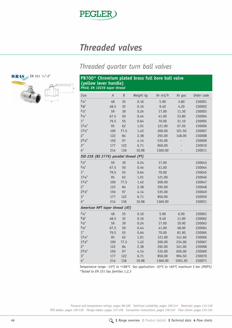
PB700* Chromium plated brass full bore ball valve (yellow lever handle)PN40, EN 10226 taper thread
A
B
Size A B Weight kg Kv m3/h Kv gas Order code1/4" 48 35 0.16 5.90 3.80 2300013/8" 48.5 35 0.16 9.40 4.20 2300021/2" 59 39 0.24 17.00 11.30 2300033/4" 67.5 50 0.44 41.00 23.80 2300041" 79.5 55 0.64 70.00 31.10 23000511/4" 95 62 1.01 121.00 67.20 23000611/2" 100 77.5 1.42 200.00 101.50 2300072" 122 84 2.38 292.00 148.00 23000821/2" 150 97 4.14 535.00 - 2300093" 177 122 6.71 850.00 - 2300104" 214 136 10.98 1360.00 - 230011
ISO 228 (BS 2779) parallel thread (PT)1/2" 59 39 0.24 17.00 2300433/4" 67.5 50 0.44 41.00 2300441" 79.5 55 0.64 70.00 23004511/4" 95 62 1.01 121.00 23004611/2" 100 77.5 1.42 200.00 2300472" 122 84 2.38 292.00 23004821/2" 150 97 4.14 535.00 2300493" 177 122 6.71 850.00 2300504" 214 136 10.98 1360.00 230051
American NPT taper thread (AT)1/4" 48 35 0.16 5.90 6.90 2300613/8" 48.5 35 0.16 9.40 11.00 2300621/2" 59 39 0.24 17.00 19.90 2300633/4" 67.5 50 0.44 41.00 48.00 2300641" 79.5 55 0.64 70.00 81.90 23006511/4" 95 62 1.01 121.00 141.60 23006611/2" 100 77.5 1.42 200.00 234.00 2300672" 122 84 2.38 292.00 341.00 23006821/2" 150 97 4.14 535.00 626.00 2300693" 177 122 6.71 850.00 994.50 2300704" 214 136 10.98 1360.00 1591.20 230071
EN 331 1/4"-2"
Temperature range: -10ºC to +186ºC Gas application: -20ºC to +60ºC maximum 5 bar (MOP5)*Tested to EN 331 Gas families 1,2,3

1 Range overview 2 Product details 3 Technical data 4 Flow charts 47
2PB700T* Chromium plated brass full bore ball valve (yellow ‘T’ handle) PN40
A
BSize A B Weight kg Kv m3/h Kv gas Order code
EN 10226 taper thread1/4" 48 36.5 0.14 5.90 3.80 2310013/8" 48.5 36.5 0.26 9.40 4.20 2310021/2" 59 40 0.27 17.00 11.30 2310033/4" 67.5 50.5 0.49 41.00 23.80 2310041" 79.5 55 0.72 70.00 31.10 231005
PB500 Chromium plated brass full bore ball valve (red lever handle) PN25Size A B Weight kg Kv m3/h Cv – US GPM Order code
EN 10226 taper thread1/4" 48 35 0.15 5.90 2420013/8" 48.5 35 0.15 9.40 2420021/2" 59 39 0.23 17.00 2420033/4" 67.5 50 0.40 41.00 2420041" 79.5 55 0.61 70.00 24200511/4" 95 62 0.95 121.00 24200611/2" 100 77.5 1.33 200.00 2420072" 122 84 2.18 292.00 24200821/2" 150 97 3.75 535.00 2420093" 177 122 6.20 850.00 2420104" 214 136 10.45 1360.00 242011
ISO 228 (BS 2779) parallel thread (PT)1/2" 59 39 0.23 17.00 2420233/4" 67.5 50 0.40 41.00 2420241" 79.5 55 0.61 70.00 24202511/4" 95 62 0.95 121.00 24202611/2" 100 77.5 1.33 200.00 2420272" 122 84 2.18 292.00 24202821/2" 150 97 3.75 535.00 2420293" 177 122 6.20 850.00 242030
American NPT taper thread (AT)1/2" 59 39 0.23 17.00 19.90 2420433/4" 67.5 50 0.40 41.00 48.00 2420441" 79.5 55 0.61 70.00 81.90 24204511/4" 95 62 0.95 121.00 141.60 24204611/2" 100 77.5 1.33 200.00 234.00 2420472" 122 84 2.18 292.00 341.60 24204821/2" 150 97 3.75 535.00 626.00 2420493" 177 122 6.20 850.00 994.50 2420504" 214 136 10.45 1360.00 1591.20 242051
A
B
EN 331
Pressure and temperature ratings: pages 98-108 Technical suitability: pages 109-114 Materials: pages 115-128PED tables: pages 129-136 Flange tables: pages 137-138 Connection instructions: pages 139-142 Flow charts: pages 143-155
Temperature range: -10ºC to +186ºC Gas application: -20ºC to +60ºC maximum 5 bar (MOP5)*Tested to EN 331 Gas families 1,2,3
Temperature range: -10ºC to +150ºC
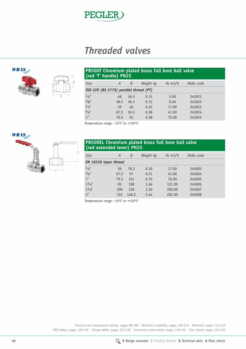
48 1 Range overview 2 Product details 3 Technical data 4 Flow charts
Threaded valves
PB500EL Chromium plated brass full bore ball valve (red extended lever) PN25Size A B Weight kg Kv m3/h Order code
EN 10226 taper thread1/2" 59 78.3 0.30 17.00 2450033/4" 67.5 97 0.51 41.00 2450041" 79.5 101 0.70 70.00 24500511/4" 95 108 1.04 121.00 24500611/2" 100 128 1.50 200.00 2450072" 124 146.2 2.44 292.00 245008
A
B
Pressure and temperature ratings: pages 98-108 Technical suitability: pages 109-114 Materials: pages 115-128PED tables: pages 129-136 Flange tables: pages 137-138 Connection instructions: pages 139-142 Flow charts: pages 143-155
PB500T Chromium plated brass full bore ball valve (red ‘T’ handle) PN25Size A B Weight kg Kv m3/h Order code
ISO 228 (BS 2779) parallel thread (PT)1/4" 48 36.5 0.15 5.90 2430213/8" 48.5 36.5 0.15 9.40 2430221/2" 59 40 0.22 17.00 2430233/4" 67.5 50.5 0.38 41.00 2430241" 79.5 55 0.58 70.00 243025
B
A
Temperature range: -10ºC to +150ºC
Temperature range: -10ºC to +150ºC

1 Range overview 2 Product details 3 Technical data 4 Flow charts 49
2PB500* Yellow Chromium plated brass full bore ball valve (yellow lever handle) PN25
Size A B Weight kg Kv m3/h Cv – US GPM Order code
EN 10226 taper thread1/4" 48 35 0.15 5.90 2421013/8" 48.5 35 0.15 9.40 2421021/2" 59 39 0.23 17.00 2421033/4" 67.5 50 0.40 41.00 2421041" 79.5 55 0.61 70.00 24210511/4" 95 62 0.95 121.00 24210611/2" 100 77.5 1.33 200.00 2421072" 122 84 2.18 292.00 24210821/2" 150 97 3.75 535.00 2421093" 177 122 6.20 850.00 2421104" 214 136 10.45 1360.00 242111
American NPT taper thread (AT)1/4" 48 35 0.15 5.90 6.90 2421213/8" 48.5 35 0.15 9.40 11.00 2421221/2" 59 39 0.23 17.00 19.90 2421233/4" 67.5 50 0.40 41.00 48.00 2421241" 79.5 55 0.61 70.00 81.90 24212511/4" 95 62 0.95 121.00 141.60 24212611/2" 100 77.5 1.33 200.00 234.00 2421272" 122 84 2.18 292.00 314.60 242128
A
B
DZR threaded ball valves
A
B
PB550DR Full bore DZR lever ball valveBlue lever handle, female ends, PN25, EN 10226 taper thread
Size A B Weight kg Kv m3/h Order code1/2" 59 39 0.23 17.00 2452013/4" 68 51 0.41 41.00 2452021" 80 56 0.61 70.00 24520311/4" 95 63 0.94 121.00 24520411/2" 100 78 1.33 200.00 2452052" 124 86 2.21 292.00 245206
EN 331 1/4"-2"
Pressure and temperature ratings: pages 98-108 Technical suitability: pages 109-114 Materials: pages 115-128PED tables: pages 129-136 Flange tables: pages 137-138 Connection instructions: pages 139-142 Flow charts: pages 143-155
Temperature range: -10ºC to +150ºC Gas application: -20ºC to +60ºC maximum 5 bar (MOP5)*Tested to EN 331 Gas families 1,2,3
Temperature range: -10ºC to +150ºC

50 1 Range overview 2 Product details 3 Technical data 4 Flow charts
Threaded valves
PB560 DZR combi ball valve and strainer with tee handleThreaded ends to EN 10226, PN20
Size A B Weight kg Order code3/4" blue tee 143 52 0.86 2455003/4" red tee 143 52 0.86 245501
B
A
Pressure and temperature ratings: pages 98-108 Technical suitability: pages 109-114 Materials: pages 115-128PED tables: pages 129-136 Flange tables: pages 137-138 Connection instructions: pages 139-142 Flow charts: pages 143-155
A
B
PB550DR EL DZR Brass full bore ball valve with lever handlePN25, EN 10226 taper thread
Size A B Weight kg Kv m3/h Order code1/2" 59 78.3 0.30 17.00 2452833/4" 68 97 0.51 41.00 2452841" 80 101 0.70 70.00 24528511/4" 95 108 1.04 212.00 24528611/2" 100 128 1.50 200.00 2452872" 124 146.2 2.44 292.00 245288
A
B
PB550DR LS DZR Brass full bore ball valve with lockshieldPN25, EN 10226 taper thread
Size A B Weight kg Kv m3/h Order code1/2" 59 45 0.21 17.00 2452603/4" 68 53 0.37 41.00 2452611" 80 58 0.57 70.00 24526211/4" 95 65 1.15 212.00 24526311/2" 100 81 1.21 200.00 2452642" 124 89 2.79 292.00 245265
B
A
PB550DR T DZR Brass full bore ball valveBlue tee handle, female ends, PN25, EN 10226 taper thread
Size A B Weight kg Kv m3/h Order code1/2" 59 39 0.22 17.00 2452113/4" 67 51 0.38 41.00 2452121" 80 56 0.58 70.00 245213
Temperature range: -10ºC to +150ºC
Temperature range: -10ºC to +150ºC
Temperature range: -10ºC to +150ºC
Temperature range: -10ºC to +150ºC

1 Range overview 2 Product details 3 Technical data 4 Flow charts 51
2
A
B
PB100* Chromium plated brass full bore ball valve(Red lever handle)PN25 to 2", PN16 21/2", 3" and 4"
Temperature range: -10ºC to +150ºC*PBSEK, LD and PDK are not suitable for use with PB100 ball valves.
Size A B Weight kg Kv m3/h Cv – US GPM Order code
EN 10226 taper thread1/2" 50 46 0.18 17.00 2700013/4" 58 50 0.25 41.00 2700021" 69 52 0.38 70.00 27000311/4" 81 70 0.62 121.00 27000411/2" 88.5 76 0.84 200.00 2700052" 110 83 1.45 292.00 27000621/2" 136 109 3.00 535.00 2700073" 163 119 4.50 850.00 2700084" 192 155 7.50 1360.00 270009
ISO 228 (BS 2779) parallel thread (PT)1/2" 50 46 0.18 17.00 2700213/4" 58 50 0.25 41.00 2700221" 69 52 0.38 70.00 27002311/4" 81 70 0.62 121.00 27002411/2" 88.5 76 0.84 200.00 2700252" 110 83 1.45 292.00 270026
American NPT taper thread (AT)1/2" 50 46 0.18 17.00 19.90 2700413/4" 58 50 0.25 41.00 48.00 2700421" 69 52 0.38 70.00 81.90 27004311/4" 81 70 0.62 121.00 141.60 27004411/2" 88.5 76 0.84 200.00 234.00 2700452" 110 83 1.45 292.00 341.60 27004621/2" 136 109 3.00 535.00 626.00 2700473" 163 119 4.50 850.00 994.50 2700484" 192 155 7.50 1360.00 1591.20 270049
B
A
PB560EXT DZR combi ball valve and strainer with extended tee handleThreaded ends to EN 10226, PN20
Size A B Weight kg Order code3/4" blue tee 143 99 0.95 2455023/4" red tee 143 99 0.95 245503
Pressure and temperature ratings: pages 98-108 Technical suitability: pages 109-114 Materials: pages 115-128PED tables: pages 129-136 Flange tables: pages 137-138 Connection instructions: pages 139-142 Flow charts: pages 143-155
Temperature range: -10ºC to +150ºC

52 1 Range overview 2 Product details 3 Technical data 4 Flow charts
Threaded valves
Pattern No. Suitable for Order code
LD1 1/4", 3/8", 1/2" 258001LD2 3/4", 1", 11/4" 258002LD3 11/2", 2" 258003
Padlock and key (suitable for PB700, PB500 and PB300 ranges)
Pattern No. Suitable for Order code
PDK3 1/4", 3/8", 1/2", 3/4", 1", 11/4" 258011PDK4 11/2", 2" 258012
PBSEK Stem extension kit (suitable for PB700, PB500 andPB300 ranges)
Locking device (for standard lever handle products suitable forPB700, PB500 and PB300 ranges)
Pattern No. Suitable for Order code
PBSEK7 1/4", 3/8", 1/2", 15mm 227027PBSEK8 3/4", 1", 11/4", 22mm, 28mm, 35mm 227028PBSEK9 11/2", 2", 42mm, 54mm 227029PBSEK10 21/2" 227030PBSEK11 3", 4" 227031
Ball valve accessories
Lockshield key (suitable for PB350/550 DR LS)
Pattern No. Suitable for Weight kg Order code
PB LS cross key 1/2" - 11/4" 15mm - 35mm 0.11 227040PB LS cross key 11/2" - 2" 42mm - 54mm 0.38 227041
Pressure and temperature ratings: pages 98-108 Technical suitability: pages 109-114 Materials: pages 115-128PED tables: pages 129-136 Flange tables: pages 137-138 Connection instructions: pages 139-142 Flow charts: pages 143-155

1 Range overview 2 Product details 3 Technical data 4 Flow charts 53
2
PB1000 Ballomax steel ball valveBSP parallel female ends, standard PN40, lever operated
Size A B Weight kg Kv m3/h Order code1/2" x 1/2" 61100015 65 116 0.60 6.00 139513/4" x 3/4" 64100020 75 115 0.70 20.00 139521" x 1" 64100025 90 120 0.90 26.00 1395311/4" x 11/4" 64100032 105 124 1.20 43.00 1395411/2" x 11/2" 64100040 120 129 1.90 64.00 139552" x 2" 64100050 145 135 2.90 100.00 13956
A
B
PB1001 Ballomax steel ball valveBSP parallel female thread x weld, standard PN40, lever operated
Size A B C Weight kg Kv m3/h Order code1/2" x 1/2" 61101015 33 105 116 0.70 6.00 139573/4" x 3/4" 64101020 38 115 115 0.80 20.00 139621" x 1" 64101025 45 115 120 0.90 26.00 1395811/4" x 11/4" 64101032 53 139 124 1.30 43.00 1395911/2" x 11/2" 64101040 60 130 129 2.00 64.00 139602" x 2" 64101050 73 150 135 2.90 100.00 13961
A B
C
Ballomax steel ball valves
Hot tapping tool kit with caseStandard PN25
Size Order code
DN15-50mm 68500015 14007DN65-100mm 68500100 14008
Ballomax accessories
Pressure and temperature ratings: pages 98-108 Technical suitability: pages 109-114 Materials: pages 115-128PED tables: pages 129-136 Flange tables: pages 137-138 Connection instructions: pages 139-142 Flow charts: pages 143-155

54 1 Range overview 2 Product details 3 Technical data 4 Flow charts
Threaded valves
Size A B C D Weight kg Kv m3/h Order code1/2" 93 45 45 89 0.26 9.40 2620013/4" 93 45 50 94 0.32 17.00 262002
PB50HU Chrome plated hose union ball type bibtapRed lever
Size A B C D Weight kg Cv Order code1/2" 93 45 45 86 0.22 9.40 262003
PB50 Chrome plated ball type bibtap with 3/4" American thread on noseRed lever
D
B
A
C
A
B
C
D
Size A B C D Weight kg Kv m3/h Order code1/2" 88 45 45 105 0.28 9.40 2620213/4" 88 45 50 105 0.36 17.00 262022
PB52HU Chrome plated brass hose union ball type bib tapA
B
C
D
A
B
1111BV Brass three way vent valveT port, ISO 228 parallel threads, PN25, nickel plated
Size A B Weight kg Kv m3/h Order code
1" 104 76 0.63 70.00 24510011/4" 119 82 1.10 121.00 24510111/2" 139 97 2.08 200.00 2451022" 166 120 3.13 292.00 245103
Pressure and temperature ratings: pages 98-108 Technical suitability: pages 109-114 Materials: pages 115-128PED tables: pages 129-136 Flange tables: pages 137-138 Connection instructions: pages 139-142 Flow charts: pages 143-155

1 Range overview 2 Product details 3 Technical data 4 Flow charts 55
2
1060A Bronze swing type check valveBS 5154 PN25 series B, metal disk
Size A B Weight kg Flow l/s Kv m3/h Cv – US GPM Order code
EN 10226 taper thread1/2" 62 45 0.38 0.04 1.80 122007
0.10 3.700.20 5.100.40 5.70
3/4" 76 55 0.58 0.04 2.70 1220080.10 5.500.40 13.601.00 15.30
1" 83 60 0.86 0.01 7.70 1220090.20 13.900.30 18.401.00 25.30
11/4" 94 65 1.26 0.20 15.00 1220100.30 20.600.40 25.301.00 32.60
11/2" 105 75 1.66 0.40 30.30 1220110.60 40.200.80 48.503.00 54.40
2" 125 90 2.66 0.60 42.00 1220120.80 54.001.50 86.204.00 98.00
21/2" 148 110 4.80 1.50 97.60 1220133.00 135.304.00 156.00
3" 175 125 6.79 2.00 144.60 1220143.00 168.405.00 229.00
4" 222 130 13.07 - - 122015
ISO 228 (BS 2779) parallel thread (PT)1/2" 62 45 0.38 0.04 1.80 122047
0.10 3.700.20 5.100.40 5.70
3/4" 76 55 0.58 0.04 2.70 1220480.10 5.500.40 13.601.00 15.30
1" 83 60 0.86 0.01 7.70 1220490.20 13.900.30 18.401.00 25.30
B
A
Threaded check valves
Pressure and temperature ratings: pages 98-108 Technical suitability: pages 109-114 Materials: pages 115-128PED tables: pages 129-136 Flange tables: pages 137-138 Connection instructions: pages 139-142 Flow charts: pages 143-155
Temperature range: -10ºC to +186ºC

56 1 Range overview 2 Product details 3 Technical data 4 Flow charts
Threaded valves
1060A Bronze swing type check valve – continuedBS 5154 PN25 series B, metal disk
Size A B Weight kg Flow l/s Kv m3/h Cv Order code
ISO 228 (BS 2779) parallel thread (PT)
11/4" 94 65 1.26 0.20 15.00 1220500.30 20.600.40 25.301.00 32.60
11/2" 105 75 1.66 0.40 30.30 1220510.60 40.200.80 48.503.00 54.40
2" 125 90 2.66 0.60 42.00 1220520.80 54.001.50 86.204.00 98.00
American NPT taper thread (AT)1/2" 62 45 0.38 0.04 1.80 2.10 122027
0.10 3.70 4.300.20 5.10 5.900.40 5.70 6.50
3/4" 76 55 0.58 0.04 2.70 3.10 1220280.10 5.50 6.300.40 13.60 15.601.00 15.30 17.60
1" 83 60 0.86 0.01 7.70 8.80 1220290.20 13.90 16.000.30 18.40 21.10
11/4" 94 65 1.26 0.20 15.00 17.2 1220300.30 20.60 23.70.40 25.30 29.11.00 32.60 37.5
11/2" 105 75 1.66 0.40 30.30 34.80 1220310.60 40.20 46.200.80 48.50 55.703.00 54.40 62.50
2" 125 90 2.66 0.60 42.00 48.30 1220320.80 54.00 62.001.50 86.20 99.004.00 98.00 112.60
21/2" 148 110 4.80 1.50 97.60 1220333.00 135.304.00 156.00
3" 175 125 6.79 2.00 144.60 1220343.00 168.405.00 229.00
Pressure and temperature ratings: pages 98-108 Technical suitability: pages 109-114 Materials: pages 115-128PED tables: pages 129-136 Flange tables: pages 137-138 Connection instructions: pages 139-142 Flow charts: pages 143-155
B
A
Temperature range: -10ºC to +186ºC

1 Range overview 2 Product details 3 Technical data 4 Flow charts 57
21039 Horizontal lift type check valveBS 5154 PN32 series B metal disk
Size A B Weight kg Flow l/s Kv m3/h Order code
EN 10226 taper thread1/2" 57 30 0.28 0.025 0.80 119007
0.050 1.500.100 1.900.200 2.60
3/4" 65 40 0.44 0.075 2.40 1190080.100 2.900.150 3.400.200 3.50
1" 78 45 0.68 0.050 1.90 1190090.100 3.600.200 6.300.400 8.50
11/4" 89 55 1.14 0.060 2.20 1190100.080 2.900.200 6.800.600 13.90
11/2" 100 60 1.46 0.100 3.90 1190110.300 10.700.500 16.800.700 21.40
2" 121 65 2.24 0.200 6.90 1190120.400 13.400.800 25.401.400 39.70
ISO 228 (BS 2779) parallel thread (PT)1/2" 57 30 0.025 0.80 119047
0.050 1.500.100 1.900.200 2.60
3/4" 65 40 0.075 2.40 1190480.100 2.900.150 3.400.200 3.50
1" 78 45 0.050 1.90 1190490.100 3.600.200 6.300.400 8.50
B
A
Pressure and temperature ratings: pages 98-108 Technical suitability: pages 109-114 Materials: pages 115-128PED tables: pages 129-136 Flange tables: pages 137-138 Connection instructions: pages 139-142 Flow charts: pages 143-155
Temperature range: -10ºC to +198ºC

58 1 Range overview 2 Product details 3 Technical data 4 Flow charts
Threaded valves
Size A B Weight kg Flow l/s Kv m3/h Order code1/2" 58 34 0.27 0.04 1.80 124007
0.10 3.700.20 5.100.40 5.70
3/4" 72 40 0.48 0.04 2.70 1240080.10 5.500.40 13.601.00 15.30
1" 83 51 0.72 0.01 7.70 1240090.20 13.900.30 18.401.00 25.30
1062 Forged brass swing type check valveBS 5154 PN25 Series B, metal disk, EN 10226 taper thread
Size A B Weight kg Order code
ISO 228 (BS 2779) parallel thread (PT)1/2" 49.5 34 0.12 1241213/4" 57.5 41.5 0.23 1241221" 61.5 47 0.25 12412311/4" 66 58.5 0.39 12412411/2" 76 69 0.58 1241252" 87 84.5 0.85 12412621/2" 100 103 1.38 1241273" 110 112 1.97 1241284" 114 145 2.83 124129
1063 Forged brass spring check valve3/8" to 1" 12bar, 11/4" to 2" 10bar, 21/2" to 4" 8bar
A
B
A
B
Pressure and temperature ratings: pages 98-108 Technical suitability: pages 109-114 Materials: pages 115-128PED tables: pages 129-136 Flange tables: pages 137-138 Connection instructions: pages 139-142 Flow charts: pages 143-155
Temperature range: -10ºC to +186ºC
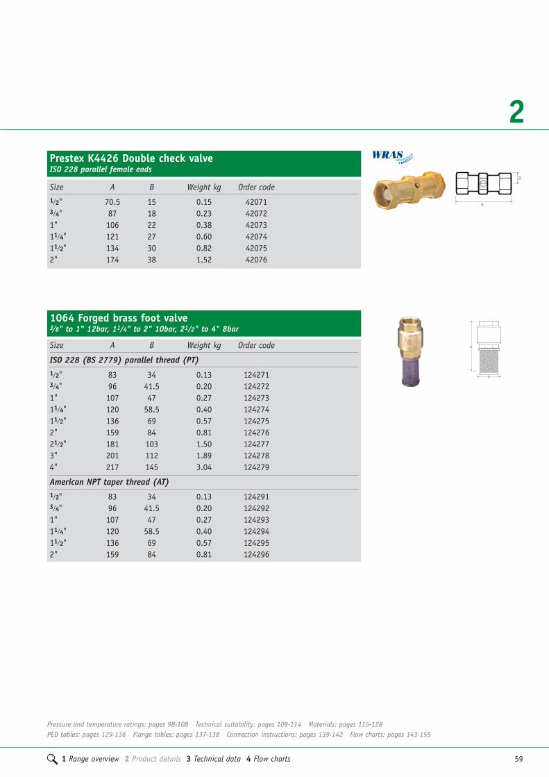
1 Range overview 2 Product details 3 Technical data 4 Flow charts 59
2Prestex K4426 Double check valveISO 228 parallel female ends
B
A
Size A B Weight kg Order code1/2" 70.5 15 0.15 420713/4" 87 18 0.23 420721" 106 22 0.38 4207311/4" 121 27 0.60 4207411/2" 134 30 0.82 420752" 174 38 1.52 42076
Size A B Weight kg Order code
ISO 228 (BS 2779) parallel thread (PT)1/2" 83 34 0.13 1242713/4" 96 41.5 0.20 1242721" 107 47 0.27 12427311/4" 120 58.5 0.40 12427411/2" 136 69 0.57 1242752" 159 84 0.81 12427621/2" 181 103 1.50 1242773" 201 112 1.89 1242784" 217 145 3.04 124279
American NPT taper thread (AT)1/2" 83 34 0.13 1242913/4" 96 41.5 0.20 1242921" 107 47 0.27 12429311/4" 120 58.5 0.40 12429411/2" 136 69 0.57 1242952" 159 84 0.81 124296
1064 Forged brass foot valve3/8" to 1" 12bar, 11/4" to 2" 10bar, 21/2" to 4" 8bar
A
B
Pressure and temperature ratings: pages 98-108 Technical suitability: pages 109-114 Materials: pages 115-128PED tables: pages 129-136 Flange tables: pages 137-138 Connection instructions: pages 139-142 Flow charts: pages 143-155

60 1 Range overview 2 Product details 3 Technical data 4 Flow charts
Threaded valves
1029 Bronze globe valveBS 5154 PN32 series B/NM, non metallic renewable disk
Size A B Weight kg Kv m3/h Cv Order code
EN 10226 taper thread1/4" 48 76 0.20 0.70 1100053/8" 46 76 0.22 1.10 1100061/2" 57 95 0.38 2.00 1100073/4" 65 98 0.54 5.00 1100081" 78 114 0.84 10.00 11000911/4" 89 138 1.36 16.00 11001011/2" 100 159 1.76 23.00 1100112" 121 170 2.62 42.00 110012
ISO 228 (BS 2779), parallel thread (PT)1/2" 57 95 0.38 2.00 1100473/4" 65 98 0.54 5.00 1100481" 78 114 0.84 10.00 11004911/4" 89 138 1.36 16.00 11005011/2" 100 159 1.76 23.00 1100512" 121 170 2.62 42.00 110052
American NPT taper thread (AT)1/2" 57 95 0.38 2.00 2.30 1100273/4" 65 98 0.54 5.00 5.90 1100281" 78 114 0.84 10.00 11.70 11002911/4" 89 138 1.36 16.00 18.70 11003011/2" 100 159 1.76 23.00 26.90 1100312" 121 170 2.62 42.00 49.10 110032
Threaded globe valves
A
BFULLYOPEN
1031 Bronze globe valveBS 5154 PN32 series B, metal disk
Size A B Weight kg Kv m3/h Order code
EN 10226 taper thread1/2" 57 95 0.39 2.30 1120073/4" 65 98 0.55 5.90 1120081" 78 114 0.87 11.70 11200911/4" 89 138 1.45 18.70 11201011/2" 100 159 1.83 26.90 1120112" 121 170 2.61 49.10 112012
A
BFULLYOPEN
Pressure and temperature ratings: pages 98-108 Technical suitability: pages 109-114 Materials: pages 115-128PED tables: pages 129-136 Flange tables: pages 137-138 Connection instructions: pages 139-142 Flow charts: pages 143-155
Temperature range: -10ºC to +198ºC
Temperature range: -10ºC to +198ºC

1 Range overview 2 Product details 3 Technical data 4 Flow charts 61
2
V954 Bronze strainerFemale x female, EN 10226 Taper thread, PN32
B
A
Size A B Weight kg Order code1/2" 70 58 0.36 154903/4" 80 75 0.54 154911" 100 88 0.85 1549211/4" 120 108 1.34 1549311/2" 130 124 1.67 154942" 160 161 3.13 15495
V913 Bronze strainer, Y patternFemale x female, EN 10226 Taper thread, PN16 Series B
B
A
Size A B Weight kg Order code1/2" 58 44 0.23 153483/4" 69 47 0.32 153491" 82 58 0.45 1535011/4" 98 68 0.74 1535111/2" 109 78 0.92 153522" 131 98 1.06 15353
Bronze threaded strainers
Pressure and temperature ratings: pages 98-108 Technical suitability: pages 109-114 Materials: pages 115-128PED tables: pages 129-136 Flange tables: pages 137-138 Connection instructions: pages 139-142 Flow charts: pages 143-155
Temperature range: -10ºC to +198ºC
Temperature range: -10ºC to +120ºC

62 1 Range overview 2 Product details 3 Technical data 4 Flow charts
Threaded valves
Rg
A
C
E
Ø63
D
B
Circulation valves
P603 Bronze circulation valveISO 228-G parallel thread, female x female
Weight OrderSize A B C D E kg code1/2" DN15 fxf 30°-50°C 57 75 35.5 98 136 0.64 165003/4" DN20 fxf 30°-50°C 57 75 45 125 147 0.82 16501
P604 Bronze circulation valveISO 228-G parallel thread, male x male
Weight OrderSize A B C D E kg code1/2" DN15 mxm 30°-50°C 57 75 35.5 98 136 0.62 165053/4" DN20 mxm 30°-50°C 57 75 34 103 136 0.71 16506
P605 Bronze circulation valveISO 228-G parallel thread, female x female
Weight OrderSize A B C D E kg code1/2" DN15 fxf 50°-60°C 57 75 35.5 98 136 0.63 165023/4" DN20 fxf 50°-60°C 57 75 45 125 147 0.82 165031" DN25 fxf 50°-60°C 57 75 51.5 136 150 0.96 16504
P606 Bronze circulation valveISO 228-G parallel thread, male x male
Weight OrderSize A B C D E kg code1/2" DN15 mxm 50°-60°C 57 75 35.5 98 136 0.63 165073/4" DN20 mxm 50°-60°C 57 75 51.5 103 136 0.73 165081" DN25 mxm 50°-60°C 57 75 40 113 138.5 0.78 16509
Pressure and temperature ratings: pages 98-108 Technical suitability: pages 109-114 Materials: pages 115-128PED tables: pages 129-136 Flange tables: pages 137-138 Connection instructions: pages 139-142 Flow charts: pages 143-155

1 Range overview 2 Product details 3 Technical data 4 Flow charts 63
2
PCV1 Circulation valve regulation cartridge
Size Order code
DN15 16510DN20 16511
PCV2 Circulation valve regulation cartridge
Size Order code
DN15 16512DN20 16513DN25 16514
Circulation valve accessories
Bimetallic thermometer for Circulation valves
Stop and drain unit for Circulation valves
Order code
16518
Order code
16519
Insulation jacket
Description A B C D E Order code
For circulation valve DN15 143 162 82 41 54 16515For circulation valve DN20 143 162 90 41 54 16516For circulation valve DN25 157 162 110 55 54 16517
RgA
C
B
D
E
Pressure and temperature ratings: pages 98-108 Technical suitability: pages 109-114 Materials: pages 115-128PED tables: pages 129-136 Flange tables: pages 137-138 Connection instructions: pages 139-142 Flow charts: pages 143-155

64 1 Range overview 2 Product details 3 Technical data 4 Flow charts
Threaded valves
Ballofix isolating ball valve – threadedMale x male, chrome plated, screw driver operation
Size A Weight kg Order code1/2" 3390ZA 45 0.10 13356
Ballofix isolating ball valve – threadedFemale x female, screw driver operation
Size A Weight kg Order code1/4" 3205YA 45 0.09 131581/2" 3350YA 47 0.11 135323/4" 3450YA 65 0.23 135591" 3550YA 62 0.42 13573
A
A
Ballofix isolating ball valve – threadedFemale x female, screw driver operation
Size A Weight kg Order code1/4" x 1/4" 3205ZA 45 0.08 131613/8" x 3/8" 3250ZA 46 0.07 131891/2" x 1/2" 3350ZA 47 0.11 135353/4" x 3/4" 3450ZA 65 0.23 13560
Ballofix isolating ball valve – threadedMale x female, screw driver operation
Size A Weight kg Order code1/4" x 1/4" 3200YA 44 0.07 131483/8" x 3/8" 3210YA 45 0.06 131661/2" x 1/2" 3310YA 44 0.10 135383/4" x 3/4" 3410YA 63 0.20 133741" x 1" 3510YA 61 0.36 13445
A
A
Ballofix DZR threaded isolating ball valves
Pressure and temperature ratings: pages 98-108 Technical suitability: pages 109-114 Materials: pages 115-128PED tables: pages 129-136 Flange tables: pages 137-138 Connection instructions: pages 139-142 Flow charts: pages 143-155

1 Range overview 2 Product details 3 Technical data 4 Flow charts 65
2
Ballofix isolating ball valve – threadedMale x female, plastic lever operation
Size A Weight kg Order code1/2" x 1/2" 3310YP 44 0.10 13226
Ballofix isolating ball valve – threadedMale x female, chrome plated, plastic lever operation
Size A Weight kg Order code1/2" x 1/2" 3310ZP 44 0.10 13228
A
A
Ballofix radiator valve – straight pattern BSP parallel female thread x male iron union, screw driver operation
Size A Weight kg Order code3/4" 5060BA 82 0.37 13367
A
Ballofix radiator valve – angle patternCompression x male iron union, screw driver operation
Size A Weight kg Order code
15mm x 1/2" 5045CA 59 0.28 13242BALLOFIX
A
Ballofix isolating ball valve – threadedMale x female, chrome plated, screw driver operation
Size A Weight kg Order code1/4" x 1/4" 3200ZA 44 0.07 131511/2" x 1/2" 3310ZA 44 0.26 135393/4" x 3/4" 3410ZA 63 0.19 133771" x 1" 3510ZA 61 0.36 13448
A
Pressure and temperature ratings: pages 98-108 Technical suitability: pages 109-114 Materials: pages 115-128PED tables: pages 129-136 Flange tables: pages 137-138 Connection instructions: pages 139-142 Flow charts: pages 143-155

66 1 Range overview 2 Product details 3 Technical data 4 Flow charts
Threaded valves
Ballofix filter valve BSP parallel female ends, plastic lever operation
Size A Weight kg Order code1/2" 33624ZP 45 0.12 14814
A
Ballofix gas valveBSP taper female ends, screw driver operation
Size A Weight kg Order code1/2" 33504BGA 56 0.14 13282
A
Ballofix draincockScrew driver operation
Size A Weight kg Order code1/2" 5095CA Chrome Plated 26 0.08 131761/2" 5095BA Nickel 26 0.08 13175
BALLOFIX
A
A
B
SW
Prestex 775 Brass automatic air vent10bar at 120°C
Size A B SW Weight kg Order code1/2" 47 106 26 0.12 538009
Automatic air vent
Pressure and temperature ratings: pages 98-108 Technical suitability: pages 109-114 Materials: pages 115-128PED tables: pages 129-136 Flange tables: pages 137-138 Connection instructions: pages 139-142 Flow charts: pages 143-155

1 Range overview 2 Product details 3 Technical data 4 Flow charts 67
2
1832 Bronze gland cockMale x hose union, 10bar 120°C, ISO 228 (BS 2779), parallel thread (PT).Supplied complete with malleable iron lever
Size A B C Weight kg Kv m3/h Order code1/2" 93 10.3 86 0.44 17.00 1300073/4" 117 13.5 95 0.76 41.00 1300081" 145 15.9 121 1.32 70.00 130009
A
B
C
Small plastic handle - with hexagon spigot
Order code
CPT0059 Black 13712
Large plastic handle - with hexagon spigot
Order code
CPT0073 Black 13721
Ballofix accessories
Draincocks
Small plastic handle - with screw
Order code
ERG Black 13724ERG Red 13728ERG Blue 13729ERG Chrome 13732
Large plastic handle - with screw
Order code
ERG Black 13725
Pressure and temperature ratings: pages 98-108 Technical suitability: pages 109-114 Materials: pages 115-128PED tables: pages 129-136 Flange tables: pages 137-138 Connection instructions: pages 139-142 Flow charts: pages 143-155
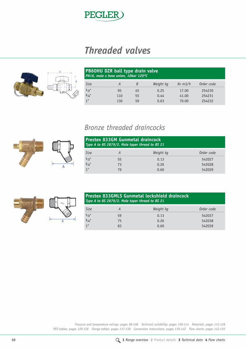
68 1 Range overview 2 Product details 3 Technical data 4 Flow charts
Threaded valves
PB60HU DZR ball type drain valvePN16, male x hose union, 10bar 120ºC
Size A B Weight kg Kv m3/h Order code1/2" 95 45 0.25 17.00 2542303/4" 110 55 0.44 41.00 2542311" 130 59 0.63 70.00 254232
B
A
Prestex 833GM Gunmetal draincockType A to BS 2879/2. Male taper thread to BS 21
Size A Weight kg Order code1/2" 55 0.13 5420273/4" 73 0.26 5420281" 79 0.60 542029
A
Prestex 833GMLS Gunmetal lockshield draincockType A to BS 2879/2. Male taper thread to BS 21
Size A Weight kg Order code1/2" 59 0.13 5420373/4" 75 0.26 5420381" 83 0.60 542039
A
Bronze threaded draincocks
Pressure and temperature ratings: pages 98-108 Technical suitability: pages 109-114 Materials: pages 115-128PED tables: pages 129-136 Flange tables: pages 137-138 Connection instructions: pages 139-142 Flow charts: pages 143-155

1 Range overview 2 Product details 3 Technical data 4 Flow charts 69
2Ballorex Venturi compression commissioning valves
Valve Connection Dimensions in mm Weight Kvs Kv Loss OrderCat No. Size Size A B C D kg m3/h m3/h Factor code
900SCL DN15 15mm 99 75 164 76 0.54 0.359 0.629 0.33 15015900SCS DN15 15mm 99 75 164 76 0.54 0.746 1.620 0.21 15009900SCH DN15 15mm 99 75 164 76 0.54 1.560 2.490 0.39 16406900SCL DN20 22mm 105 75 170 79 0.72 0.746 1.430 0.27 15016900SCS DN20 22mm 105 75 170 79 0.72 1.56 5.720 0.27 15010900SCH DN20 22mm 105 75 170 79 0.72 2.95 2.820 0.31 16407900SCS DN25 28mm 118 75 177 83 1.00 2.95 12.100 0.25 15011900SCH DN25 28mm 118 75 177 83 1.00 6.01 7.540 0.15 15183900SCH DN32 35mm 135 122 241 109 1.81 6.010 13.200 0.21 15012900SCH DN40 42mm 149 122 253 113 2.51 9.200 22.000 0.17 15013900SCH DN50 54mm 167 122 265 120 3.82 17.100 36.000 0.23 15014
900SC Ballorex Venturi DZR commissioning station (FODRV)Compression ends to EN 1254/2 for copper. With regulation, isolation and flow measurement functions
Dimensions in mm Weight Kv OrderCat No. Size A B C D kg m3/h code
901SCL 15mm 62 75 128 76 0.37 1.62 15050901SCS 15mm 62 75 128 76 0.37 2.10 15044901SCL 22mm 67 75 132 79 0.51 4.26 15051901SCS 22mm 67 75 132 79 0.51 4.79 15045901SCS 28mm 81 75 140 83 0.80 12.80 15046901SCS 35mm 93 122 199 109 1.55 13.28 15047901SCS 42mm 107 122 211 113 2.12 23.30 15048901SCS 54mm 126 122 224 120 3.25 35.30 15049
901SC Ballorex Venturi DZR double regulating valve (DRV)Compression ends to EN 1254/2 for copper. With regulation and isolation functions
Compression valves
Pressure and temperature ratings: pages 98-108 Technical suitability: pages 109-114 Materials: pages 115-128PED tables: pages 129-136 Flange tables: pages 137-138 Connection instructions: pages 139-142 Flow charts: pages 143-155

70 1 Range overview 2 Product details 3 Technical data 4 Flow charts
Ballorex Venturi accessories
A
C
B
Insulation jackets for Ballorex Venturi valve
Size A B C Order code1/2" 92 112 70 152503/4" 98 118 75 152511" 110 124 80 1525211/4" 128 133 94 1525311/2" 138 140 100 152542" 153 152 118 15255
DZR Red and blue self seal test pointsMale taper connection
Size A B Weight kg Order code1/4" x 36mm 14 36 0.03 1260411/4" x 75mm 14 75 0.06 126042
910TP Red and blue Venturi test pointsMale taper thread
Size A B Weight kg Order code1/4" 14 38 0.03 15201
920EX Venturi test point extension kitMale taper thread
Size A B Weight kg Order code1/4" x 50mm 17 65 0.09 15205
A
B
B
A
A
B
Compression valves
Pressure and temperature ratings: pages 98-108 Technical suitability: pages 109-114 Materials: pages 115-128PED tables: pages 129-136 Flange tables: pages 137-138 Connection instructions: pages 139-142 Flow charts: pages 143-155

1 Range overview 2 Product details 3 Technical data 4 Flow charts 71
2Compression commissioning valves
1200C DZR double regulating valve (DRV)Compression ends to EN 1254/2. With regulation and isolation functions
Size A B Weight kg Kv m3/h Order code
15mm standard flow 133 106 0.53 2.30 12601622mm standard flow 148 106 0.59 2.48 12601728mm standard flow 171 113 0.90 7.15 12601835mm standard flow 217 120 1.29 15.08 12601942mm standard flow 235 123 1.68 20.84 12602054mm standard flow 267 138 2.97 28.89 126021
1260C Fixed orifice commissioning set (FODRV)DZR body, bonnet, disc and stem. Compression ends to EN 1254/2. With regulation,isolation and flow measurement functions
Size A B Weight kg Kv m3/h Kvs m3/h Order code
15mm low flow 133 106 0.50 0.40 0.41 12603615mm standard flow 133 106 0.49 1.86 2.15 12603722mm standard flow 148 106 0.55 2.27 4.78 12603828mm standard flow 171 113 0.86 6.11 8.11 12604435mm standard flow 217 120 1.24 12.65 15.41 12604542mm standard flow 235 123 1.62 19.00 22.23 12604654mm standard flow 267 138 2.90 28.42 48.21 126047
A
B
A
B
1250C DZR metering stationDZR body, bonnet, disc and stem. Compression ends to EN 1254/2. With flow measurement function
Size A B Weight kg Kvs m3/h Order code
15mm low flow 102 65 0.35 0.41 12608015mm standard flow 102 65 0.35 2.15 12608122mm standard flow 113 68 0.50 4.78 12608228mm standard flow 131 78 0.71 8.11 12608335mm standard flow 163 83 1.06 15.41 12608442mm standard flow 179 89 1.45 22.23 12608554mm standard flow 185 103 2.43 48.21 126086
A
B
Pressure and temperature ratings: pages 98-108 Technical suitability: pages 109-114 Materials: pages 115-128PED tables: pages 129-136 Flange tables: pages 137-138 Connection instructions: pages 139-142 Flow charts: pages 143-155

72 1 Range overview 2 Product details 3 Technical data 4 Flow charts
Compression valves
Compression gate valves
Prestex 63 Brass full bore gate valveCompression ends to EN 1254/2, PN16
A
B
A
B
Size A B Weight kg Kv m3/h Order code
15mm 72 83 0.31 14.00 50600722mm 81 93 0.47 32.00 50600828mm 90 111 0.65 57.00 50600935mm 107 124 1.26 90.00 50701042mm 113 146 1.60 129.00 50701154mm 129 174 2.70 230.00 507012
Prestex 63LS Brass full bore gate valve with lockshieldCompression ends to EN 1254/2, PN16
Size A B Weight kg Kv m3/h Order code
15mm 72 83 0.31 14.00 50603722mm 81 93 0.47 32.00 50603828mm 90 111 0.65 57.00 506039
K416GM Gunmetal full bore gate valveCompression ends to EN 1254/2, PN16
Size A B Weight kg Kv m3/h Order code
15mm 70 69 0.31 14.00 5598522mm 80 80 0.42 32.00 5598628mm 90 100 0.61 57.00 5598735mm 90 113 1.02 90.00 5598842mm 112 125 1.40 129.00 5598954mm 134 150 2.43 230.00 5599067mm 160 218 5.10 428.00 5599776mm 183 248 5.98 680.00 55998
B
A
15mm-35mm
B
A15-54mm
67-76mm
K416GMLS Gunmetal full bore gate valve with lockshieldCompression ends to EN 1254/2, PN16
Size A B Weight kg Kv m3/h Order code
15mm 70 65 0.18 14.00 5599122mm 80 75 0.37 32.00 5599228mm 90 93 0.68 57.00 5599335mm 90 110 1.14 90.00 5599442mm 112 127 1.20 129.00 5599554mm 134 147 2.61 230.00 55996
A
B
Pressure and temperature ratings: pages 98-108 Technical suitability: pages 109-114 Materials: pages 115-128PED tables: pages 129-136 Flange tables: pages 137-138 Connection instructions: pages 139-142 Flow charts: pages 143-155
Temperature range: -10ºC to +120ºC
Temperature range: -10ºC to +120ºC
Temperature range: -10ºC to +110ºC
Temperature range: -10ºC to +110ºC

1 Range overview 2 Product details 3 Technical data 4 Flow charts 73
2Compression ball valves
A
B
PB350 DZR lever ball valveDZR body. Compression ends to EN 1254/2, PN16. Blue lever handle
Size A B Weight kg Kv m3/h Order code
15mm 78 39 0.28 17.00 25420122mm 88 51 0.45 41.00 25420228mm 96 56 0.68 70.00 25420335mm 119 63 1.11 121.00 25420442mm 133 78 1.61 200.00 25420554mm 162 86 2.66 292.00 254206
A
B
PB350T DZR tee ball valveDZR body. Compression ends to EN 1254/2, PN16. Blue tee handle
Size A B Weight kg Kv m3/h Order code
15mm 78 39 0.26 17.00 25421122mm 88 51 0.42 41.00 25421228mm 96 56 0.65 70.00 254213
A
B
PB350LS DZR ball valve with lockshieldDZR body. Compression ends to EN 1254/2, PN16
Size A B Weight kg Kv m3/h Order code
15mm 78 45 0.25 17.00 25422022mm 88 54 0.41 41.00 25422128mm 96 58 0.65 70.00 25422235mm 119 65 1.06 121.00 25422342mm 133 81 1.47 200.00 25422454mm 162 89 3.06 292.00 254225
A
B
PB350EL DZR ball valve with extended leverDZR body. Compression ends to EN 1254/2, PN16
Size A B Weight kg Kv m3/h Order code
15mm 78 78 0.35 17.00 25424322mm 88 97 0.54 41.00 25424428mm 96 101 0.78 70.00 25424535mm 119 108 1.20 121.00 25424642mm 133 128 1.77 200.00 25424754mm 162 146 2.90 292.00 254248
Pressure and temperature ratings: pages 98-108 Technical suitability: pages 109-114 Materials: pages 115-128PED tables: pages 129-136 Flange tables: pages 137-138 Connection instructions: pages 139-142 Flow charts: pages 143-155
Temperature range: -10ºC to +120ºC
Temperature range: -10ºC to +120ºC
Temperature range: -10ºC to +120ºC
Temperature range: -10ºC to +120ºC

74 1 Range overview 2 Product details 3 Technical data 4 Flow charts
Compression valves
Prestex PB300 Chromium plated brass full bore ball valve (red lever handle) PN16DZR body. Compression ends to EN 1254/2, PN16
Size A B Weight kg Kv m3/h Order code
15mm 77.5 39 0.28 17.00 25400122mm 88 50 0.48 41.00 25400228mm 96 55 0.73 70.00 25400335mm 119 62 1.32 121.00 25400442mm 132.5 77.5 1.92 200.00 25400554mm 161.5 84 3.24 292.00 254006
A
B
Prestex PB300T Chromium plated brass full bore ball valve (red ‘T’ handle) PN16DZR body. Compression ends to EN 1254/2, PN16
Size A B C Weight kg Kv m3/h Order code
15mm 77.5 40 48.5 0.30 17.00 25500122mm 88 50.5 60 0.52 41.00 25500228mm 96 55 60 0.77 70.00 255003
A
B
C
A
B
Prestex PB300T Chromium plated brass full bore ball valve (green ‘T’ handle)Compression ends to EN 1254/2, PN16
Size A B C Weight kg Kv m3/h Order code
15mm 77.5 40 48.5 0.30 17.00 4501322mm 88 50.5 60 0.52 41.00 45014
A
B
C
Prestex PB300 Chromium plated brass full bore ball valve (green lever handle)Compression ends to EN 1254/2, PN16
Size A B Weight kg Kv m3/h Order code
15mm 77.5 39 0.28 17.00 4500122mm 88 50 0.48 41.00 4500228mm 96 55 0.73 70.00 45003
EN331
EN331
Pressure and temperature ratings: pages 98-108 Technical suitability: pages 109-114 Materials: pages 115-128PED tables: pages 129-136 Flange tables: pages 137-138 Connection instructions: pages 139-142 Flow charts: pages 143-155
Temperature range: -10ºC to +120ºC
Temperature range: -10ºC to +120ºC
Temperature range: -10ºC to +120ºC
Temperature range: -10ºC to +120ºC

1 Range overview 2 Product details 3 Technical data 4 Flow charts 75
2
A
B
Prestex PB300T* Chromium plated brass full bore ball valve (yellow ‘T’ handle)Compression ends to EN 1254/2, PN16
Size A B C Weight kg Kv m3/h Order code
15mm 77.5 40 48.5 0.30 17.00 25502122mm 88 50.5 60 0.52 41.00 25502228mm 96 55 60 0.77 70.00 255023
A
B
C
Prestex PB300* Chromium plated brass full bore ball valve (yellow lever handle)Compression ends to EN 1254/2, PN16
Size A B Weight kg Kv m3/h Order code
15mm 77.5 39 0.28 17.00 25401122mm 88 50 0.48 41.00 25401228mm 96 55 0.73 70.00 254013
EN331
EN331
Prestex PB300 Chromium plated brass full bore ball valve (blue lever handle)Compression ends to EN 1254/2, PN16
Size A B Weight kg Kv m3/h Order code
15mm 77.5 39 0.28 17.00 25402122mm 88 50 0.48 41.00 25402228mm 96 55 0.73 70.00 25402335mm 119 62 1.32 121.00 25402442mm 132.5 77.5 1.92 200.00 25402554mm 161.5 84 3.24 292.00 254026
A
B
Prestex PB300T Chromium plated brass full bore ball valve (blue ‘T’ handle)Compression ends to EN 1254/2, PN16
Size A B C Weight kg Kv m3/h Order code
15mm 77.5 40 48.5 0.38 17.00 25501122mm 88 50.5 60 0.52 41.00 25501228mm 96 55 60 0.77 70.00 255013
A
B
C
Pressure and temperature ratings: pages 98-108 Technical suitability: pages 109-114 Materials: pages 115-128PED tables: pages 129-136 Flange tables: pages 137-138 Connection instructions: pages 139-142 Flow charts: pages 143-155
Temperature range: -10ºC to +120ºC
Temperature range: -10ºC to +120ºC
Temperature range: -10ºC to +120ºC Gas application: -20ºC to +60ºC maximum 5 bar (MOP5)*Tested to EN 331 Gas families 1,2,3
Temperature range: -10ºC to +120ºC Gas application: -20ºC to +60ºC maximum 5 bar (MOP5)*Tested to EN 331 Gas families 1,2,3

76 1 Range overview 2 Product details 3 Technical data 4 Flow charts
Compression valves
PBSEK Stem extension kit (suitable for PB700, PB500 andPB300 ranges)
Pattern No. Suitable for Order code
PBSEK7 1/4", 3/8", 1/2", 15mm 227027PBSEK8 3/4", 1", 11/4", 22mm, 28mm, 35mm 227028PBSEK9 11/2", 2", 42mm, 54mm 227029PBSEK10 21/2" 227030PBSEK11 3", 4" 227031
Ball valve accessories
Locking device (for standard lever handle products, suitable forPB700, PB500 and PB300 ranges)
Pattern No. Suitable for Order code
LD1 1/4", 3/8", 1/2" 258001LD2 3/4", 1", 11/4" 258002LD3 11/2", 2" 258003
Padlock and key (suitable for PB700, PB500 and PB300 ranges)
Pattern No. Suitable for Order code
PDK3 1/4", 3/8", 1/2", 3/4", 1", 11/4" 258011PDK4 11/2", 2" 258012
Lockshield key (suitable for PB350/550 DR LS)
Pattern No. Suitable for Weight kg Order code
PB LS cross key 1/2" - 11/4" 15mm - 35mm 0.11 227040PB LS cross key 11/2" - 2" 42mm - 54mm 0.38 227041
Pressure and temperature ratings: pages 98-108 Technical suitability: pages 109-114 Materials: pages 115-128PED tables: pages 129-136 Flange tables: pages 137-138 Connection instructions: pages 139-142 Flow charts: pages 143-155

1 Range overview 2 Product details 3 Technical data 4 Flow charts 77
2
Ballofix double check valveCompression ends
Size A Weight kg Order code
15mm 0015YA 100 0.20 13521
A
Ballofix double check valveCompression ends
Size A Weight kg Order code
15mm 0015ZA 100 0.20 13522
A
Compression check valves
Size A Weight kg Order code
15mm 57 0.11 4206222mm 69 0.24 42063
Prestex K424 DZR single check valveCompression ends, copper x copper, BS 6282 A
Size A Weight kg Order code
15mm 58 0.18 42090
Prestex K4424CP DZR chrome plated double check valveCompression ends, copper x copper, BS 6282 A
Size A Weight kg Order code
15mm 58 0.18 4206822mm 65 0.23 4206928mm 67 0.49 42070
Prestex K4424 DZR double check valveCompression ends, copper x copper, BS 6282 A
Pressure and temperature ratings: pages 98-108 Technical suitability: pages 109-114 Materials: pages 115-128PED tables: pages 129-136 Flange tables: pages 137-138 Connection instructions: pages 139-142 Flow charts: pages 143-155

78 1 Range overview 2 Product details 3 Technical data 4 Flow charts
Compression valves
Ballofix compression isolating ball valves
Size A Weight kg Order code
15mm 3381YA 41 0.14 1354022mm 3481YA 57 0.22 1356328mm 3581YA 65 0.54 13575
Ballofix isolating ball valve – straight patternCompression ends. Screwdriver operation. DZR brass, plain finishA
A
Size A Weight kg Order code
15mm 3381ZA 41 0.14 1354322mm 3481ZA 57 0.22 1356428mm 3581ZA 65 0.54 13576
Ballofix isolating ball valve – straight patternCompression ends. Screwdriver operation. DZR brass, commercial chrome finish
Size A Weight kg Order code
15mm 3381YP 41 0.17 13541
Ballofix isolating ball valve – straight patternCompression ends. Plastic lever operation. DZR brass, plain finishA
Size A Weight kg Order code
15mm 3381ZM 41 0.17 13545
Ballofix isolating ball valve – straight patternCompression ends. Plastic CP lever operation. DZR brass, commercial chrome finishA
Pressure and temperature ratings: pages 98-108 Technical suitability: pages 109-114 Materials: pages 115-128PED tables: pages 129-136 Flange tables: pages 137-138 Connection instructions: pages 139-142 Flow charts: pages 143-155

1 Range overview 2 Product details 3 Technical data 4 Flow charts 79
2
Size A Weight kg Order code
15mm 3331YA 51 0.12 1353022mm 3431YA 53 0.25 13384
Ballofix isolating ball valve – straight patternCompression x BSP parallel female thread. Screwdriver operation. DZR, plain finish A
Size A Weight kg Order code
15mm 3381ZP 41 0.15 13544
Ballofix isolating ball valve – straight patternCompression ends. Black plastic lever operation A
Size A Weight kg Order code
15mm 3331ZA 51 0.10 13531
Ballofix isolating ball valve – straight patternCompression x BSP parallel female thread. Screwdriver operation. DZR, commercial chrome finish
Size A Weight kg Order code
15mm 3331YP 51 0.13 13233
Ballofix isolating ball valve – straight patternCompression x BSP parallel female thread. Plastic lever operation. DZR, plain finish
A
A
Size A Weight kg Order code
15mm 3331ZP 51 0.13 13236
Ballofix isolating ball valve – straight patternCompression x BSP parallel female thread. Plastic lever operation. DZR, commercial chrome finish
A
Pressure and temperature ratings: pages 98-108 Technical suitability: pages 109-114 Materials: pages 115-128PED tables: pages 129-136 Flange tables: pages 137-138 Connection instructions: pages 139-142 Flow charts: pages 143-155

80 1 Range overview 2 Product details 3 Technical data 4 Flow charts
Compression valves
Size A Weight kg Order code
15mm 3375YA 40 0.13 13311
Ballofix isolating ball valve – straight patternCompression x BSP parallel male thread. Screwdriver operation. DZR, plain finishA
Ballofix isolating ball valve – angle patternCompression ends. Screwdriver operation
Size A Weight kg Order code
15mm 3380YA 20 0.12 13321BALLOFIX
A
Ballofix isolating ball valve – angle patternCompression ends. Screwdriver operation
Size A Weight kg Order code
15mm 3380ZA 23 0.12 13324BALLOFIX
A
Ballofix isolating ball valve – angle patternCompression ends. Plastic lever operation
Size A Weight kg Order code
15mm 3380YP 20 0.13 13323BALLOFIX
A
Pressure and temperature ratings: pages 98-108 Technical suitability: pages 109-114 Materials: pages 115-128PED tables: pages 129-136 Flange tables: pages 137-138 Connection instructions: pages 139-142 Flow charts: pages 143-155

1 Range overview 2 Product details 3 Technical data 4 Flow charts 81
2Ballofix isolating ball valve – angle patternCompression ends. Plastic lever operation
Size A Weight kg Order code
15mm 3380ZP 20 0.13 13326 BALLOFIX
A
Ballofix minibore isolating ball valve – straight patternCompression ends. Screwdriver operation
Size A Weight kg Order code
15mm 1581YA 41 0.11 13108
A
Ballofix minibore isolating ball valve – straight patternCompression ends. Screwdriver operation
Size A Weight kg Order code
15mm 1581ZA 41 0.11 13111
A
Ballofix service valve – straight swivel pattern Compression x BSP union nut. Screwdriver operation
Size A Weight kg Order code
15mm x 1/2" 3140ZA 41 0.12 13133
A
Ballofix service valve – straight swivel pattern Compression x BSP union nut. Screwdriver operation
Size A Weight kg Order code
15mm x 1/2" 3140YA 41 0.12 13658
A
Ballofix compression service valves
Pressure and temperature ratings: pages 98-108 Technical suitability: pages 109-114 Materials: pages 115-128PED tables: pages 129-136 Flange tables: pages 137-138 Connection instructions: pages 139-142 Flow charts: pages 143-155

82 1 Range overview 2 Product details 3 Technical data 4 Flow charts
Compression valves
Ballofix service valve – straight swivel pattern Compression x BSP union nut. Plastic lever operation
Size A Weight kg Order code
15mm x 1/2" 3140ZP 41 0.13 13135
A
Ballofix service valve – angle swivel pattern Compression x BSP union nut. Screwdriver operation
Size A Weight kg Order code
15mm 3160YA 22 0.14 13523BALLOFIX
A
Ballofix service valve – angle swivel patternCompression x BSP union nut. Screwdriver operation
Size A Weight kg Order code
15mm 3160ZA 22 0.14 13143BALLOFIX
A
Ballofix compression filter valves
Ballofix filter valveCompression ends. Screwdriver operation. Removable filter
Size A Weight kg Order code
15mm 33615ZA 45 0.16 13304
A
Ballofix filter valveCompression ends. Screwdriver operation. Removable filter
Size A Weight kg Order code
22mm 34622ZA 50 0.27 13416
A
Pressure and temperature ratings: pages 98-108 Technical suitability: pages 109-114 Materials: pages 115-128PED tables: pages 129-136 Flange tables: pages 137-138 Connection instructions: pages 139-142 Flow charts: pages 143-155

1 Range overview 2 Product details 3 Technical data 4 Flow charts 83
2Ballofix filter valveCompression ends. Plastic lever operation
Size A Weight kg Order code
15mm 33615ZP 45 0.16 13305
A
Ballofix radiator valve - straight patternCompression x male iron union. Screwdriver operation
Size A Weight kg Order code
15mm x 1/2" 5035CA 69 0.24 13248
A
Small plastic handle - with hexagon spigot
Order code
CPT0059 Black 13712
Large plastic handle - with hexagon spigot
Order code
CPT0073 Black 13721
Ballofix accessories
Small plastic handle - with screw
Order code
ERG Black 13724ERG Red 13728ERG Blue 13729ERG Chrome 13732
Large plastic handle - with screw
Order code
ERG Black 13725
Pressure and temperature ratings: pages 98-108 Technical suitability: pages 109-114 Materials: pages 115-128PED tables: pages 129-136 Flange tables: pages 137-138 Connection instructions: pages 139-142 Flow charts: pages 143-155

84 1 Range overview 2 Product details 3 Technical data 4 Flow charts
Compression valves
Compression nuts
Compression nutBrass, plain finish
Size Order code
15mm CPT0021 1485322mm CPT0023 13686
Compression nut Brass, commercial chrome finish
Size Order code
15mm CPT0022 1368522mm CPT0024 14854
Compression ringBrass, plain finish
Size Order code
15mm CPT0044 1369822mm CPT0045 13699
Flow regulator insertTo maintain a defined flow rate
Size Flow rate Colour Order code
15mm 4 l/m Pink 1377915mm 6 l/m Grey 1378015mm 8 l/m White 1378115mm 9/10 l/m Yellow 1378215mm 12 l/m Brown 1378322mm 12 l/m Orange 1378422mm 18 l/m Brown 13785
Pressure and temperature ratings: pages 98-108 Technical suitability: pages 109-114 Materials: pages 115-128PED tables: pages 129-136 Flange tables: pages 137-138 Connection instructions: pages 139-142 Flow charts: pages 143-155

1 Range overview 2 Product details 3 Technical data 4 Flow charts 85
2
Valve Dimensions in mm No. of Weight Kvs Kv Loss OrderCat No. Size A B C D Holes kg m3/h m3/h Factor code
Standard pattern
900XSS DN65 182 185 285 100 4 13.30 37.40 78.20 0.23 15028900XSS DN80 249 200 295 100 8 16.20 72.90 169.00 0.19 15029900XSS DN100 325 220 310 160 8 23.00 129.00 360.00 0.13 15030900XSS DN125 341 250 325 160 8 30.00 190.00 502.00 0.14 15031900XSS DN150 354 285 340 160 8 36.00 348.00 1010.00 0.12 15032900XSS DN200 378 340 430 200 12 55.00 586.00 1910.00 0.09 15033900XSS DN250 411 405 465 200 12 78.00 861.00 2540.00 0.11 15034900XSS DN300 465 460 535 250 12 105.00 1513.00 4850.00 0.10 15035
Extended pattern
900XSL DN65 455 185 285 100 4 16.80 37.40 78.20 0.23 15023900XSL DN80 570 200 295 100 8 22.00 72.90 169.00 0.19 15024900XSL DN100 735 220 310 160 8 34.00 129.00 360.00 0.13 15025900XSL DN125 865 250 325 160 8 47.00 190.00 502.00 0.14 15026900XSL DN150 1010 285 340 160 8 63.00 348.00 1010.00 0.12 15027
900XS Ballorex Venturi steel commissioning station (FODRV)With regulation, isolation and flow measurement functions
Ballorex Venturi flanged commissioning valves
Valve Dimensions in mm No. of Weight Kv OrderCat No. Size A B C D Holes kg m3/h code
901XS DN65 45 185 285 100 4 6.10 148.00 15056901XS DN80 46 200 295 100 8 6.30 237.00 15057901XS DN100 52 220 310 160 8 10.60 603.00 15058901XS DN125 55 250 325 160 8 12.60 888.00 15059901XS DN150 56 285 340 160 8 14.10 2341.00 15060901XS DN200 60 340 430 200 12 23.20 2845.00 15061901XS DN250 68 405 465 200 12 33.70 4549.00 15062901XS DN300 78 460 535 250 12 48.70 7761.00 15063
901XS Ballorex Venturi steel double regulating valve (DRV)With regulation and isolation functions
A
C
D
B
C
B
D
A
A
Flanged valves
Pressure and temperature ratings: pages 98-108 Technical suitability: pages 109-114 Materials: pages 115-128PED tables: pages 129-136 Flange tables: pages 137-138 Connection instructions: pages 139-142 Flow charts: pages 143-155
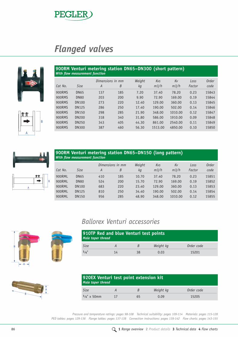
86 1 Range overview 2 Product details 3 Technical data 4 Flow charts
Flanged valves
Dimensions in mm Weight Kvs Kv Loss OrderCat No. Size A B kg m3/h m3/h Factor code
900RMS DN65 137 185 7.20 37.40 78.20 0.23 15843900RMS DN80 203 200 9.90 72.90 169.00 0.19 15844900RMS DN100 273 220 12.40 129.00 360.00 0.13 15845900RMS DN125 286 250 17.40 190.00 502.00 0.14 15846900RMS DN150 298 285 21.90 348.00 1010.00 0.12 15847900RMS DN200 318 340 31.80 586.00 1910.00 0.09 15848900RMS DN250 343 405 44.30 861.00 2540.00 0.11 15849900RMS DN300 387 460 56.30 1513.00 4850.00 0.10 15850
900RM Venturi metering station DN65–DN300 (short pattern)With flow measurement function
Dimensions in mm Weight Kvs Kv Loss OrderCat No. Size A B kg m3/h m3/h Factor code
900RML DN65 410 185 10.70 37.40 78.20 0.23 15851900RML DN80 524 200 15.70 72.90 169.00 0.19 15852900RML DN100 683 220 23.40 129.00 360.00 0.13 15853900RML DN125 810 250 34.40 190.00 502.00 0.14 15854900RML DN150 956 285 48.90 348.00 1010.00 0.12 15855
900RM Venturi metering station DN65–DN150 (long pattern)With flow measurement function
A
B
A
B
Ballorex Venturi accessories
910TP Red and blue Venturi test pointsMale taper thread
Size A B Weight kg Order code1/4" 14 38 0.03 15201
920EX Venturi test point extension kitMale taper thread
Size A B Weight kg Order code1/4" x 50mm 17 65 0.09 15205
A
B
B
A
Pressure and temperature ratings: pages 98-108 Technical suitability: pages 109-114 Materials: pages 115-128PED tables: pages 129-136 Flange tables: pages 137-138 Connection instructions: pages 139-142 Flow charts: pages 143-155

1 Range overview 2 Product details 3 Technical data 4 Flow charts 87
22Cast iron flanged commissioning valves
Size A B Weight kg Order code
DN50 230 260 12.00 15530DN65 290 293 18.00 15531DN80 310 305 23.00 15532DN100 350 323 33.50 15533DN125 400 353 49.00 15534DN150 480 388 62.00 15535DN200 600 453 96.00 15536
V952 Cast iron double regulating valveWith regulating and isolating functions
A
B
Size A B Weight kg Order code
DN50 230 260 12.00 15503DN65 290 293 18.00 15504DN80 310 305 23.00 15505DN100 350 323 33.50 15506DN125 400 353 49.00 15507DN150 480 388 62.00 15508DN200 600 453 96.00 15509
V952V VODRV Cast iron variable orifice double regulating valveWith regulating, isolating and measurement functions
A
B
Size 1 2 3 4 5 6 7 8 9 10 11 12 13 14
DN50 7.10 16.80 24.70 30.20 34.10 37.40 40.90 42.10 - - - - - -DN65 12.10 19.70 28.00 39.40 51.70 64.70 74.00 80.90 - - - - - -DN80 20.60 28.70 39.60 53.50 71.50 86.60 97.40 108.40 - - - - - -DN100 25.70 55.00 78.90 112.30 145.20 170.90 192.50 210.30 - - - - - -DN125 42.80 60.00 77.60 99.80 129.50 155.50 172.00 196.20 213.20 233.60 256.20 278.00 298.20 310.40DN150 45.50 77.90 94.30 110.90 133.50 163.80 201.40 233.90 261.90 293.00 326.50 361.30 414.30 414.30DN200 64.40 134.00 171.80 219.80 286.00 329.30 389.80 441.30 483.90 542.10 595.60 650.60 711.30 753.80
V952/V952V Kv valuesm3/h@1kg/cm2 Pressure drop
Pressure and temperature ratings: pages 98-108 Technical suitability: pages 109-114 Materials: pages 115-128PED tables: pages 129-136 Flange tables: pages 137-138 Connection instructions: pages 139-142 Flow charts: pages 143-155

88 1 Range overview 2 Product details 3 Technical data 4 Flow charts
Cast iron flanged gate valves
Size A B C Weight kg Order code
DN50 109 148 20 1.40 15540DN65 129 158 20 1.90 15541DN80 144 166 20 2.20 15542DN100 164 176 20 2.40 15543DN125 194 191 20 3.10 15544DN150 220 204 20 3.40 15545DN200 275 232 20 4.70 15546DN250 358 273 20 6.08 15547DN300 386 287 20 7.60 15548
V953 Metering station304 Stainless steel, flanges BS EN 1092-1 PN16, complete with test points andstainless steel extensions with flow measurement function
A
C B
Size A B Weight kg Kv m3/h Order code
DN65 170 222 13.10 230.00 15520DN80 180 250 18.50 360.00 15521DN100 190 303 22.30 923.00 15522DN125 200 351 38.00 1443.00 15523DN150 210 411 39.00 2077.00 15524DN200 230 498 63.00 3693.00 15525
V951 Cast iron gate valve PN6BS EN 1171:2002 PN6, 6bar from -10°C to 120°C, 5.4bar 150°C
A
B
Flanged valves
Size A B Weight kg Kv m3/h Order code
DN50 178 327 16.10 230.00 15510DN65 191 322 19.12 360.00 15511DN80 203 340 22.14 519.00 15512DN100 229 420 28.00 923.00 15513DN125 254 477 35.00 1443.00 15514DN150 267 542 43.00 2077.00 15515DN200 292 608 86.00 3693.00 15516DN250 330 750 147.00 5771.00 15517DN300 356 835 209.00 8310.00 15518
V950 Ductile iron gate valve PN16BS EN 1171:2002 PN16, 16bar from -10°C to 120°C, 11.8bar 230°C
A
B
Pressure and temperature ratings: pages 98-108 Technical suitability: pages 109-114 Materials: pages 115-128PED tables: pages 129-136 Flange tables: pages 137-138 Connection instructions: pages 139-142 Flow charts: pages 143-155

1 Range overview 2 Product details 3 Technical data 4 Flow charts 89
2
PB1006 Ballomax steel ball valveFlanged PN16, lever operated
Size A B Weight kg Kv m3/h Order code
DN65 64103065 270 144 9.90 160.00 13972DN80 64103080 280 154 13.20 280.00 13973DN100 64103100 300 193 18.30 450.00 13974DN125 61103125 325 221 25.10 690.00 13885DN150 64103150 350 245 38.20 1100.00 13886DN200 64103200 400 289 61.70 1500.00 13887DN250 64103250 650 306 140.00 2770.00 13888DN300 64103300 750 336 225.00 4620.00 13860DN350 64103350 850 395 300.00 7250.00 13861DN400 64103400 950 445 450.00 10540.00 13862DN500 64103500 1150 522 705.00 11780.00 13863
A
B
B
A
PB1005 Ballomax steel ball valveFlanged PN40, lever operated
Size A B Weight kg Kv m3/h Order code
DN15 61103015 130 116 1.50 6.00 13984DN20 64103020 150 85 2.90 14.00 13985DN25 64103025 160 89 3.50 26.00 13986DN32 64103032 180 93 4.80 43.00 13987DN40 64103040 200 108 6.20 64.00 13988DN50 64103050 230 114 8.20 100.00 13971
A
B
Ballomax steel flanged isolating ball valves
DN65-DN100
DN125-DN500
Pressure and temperature ratings: pages 98-108 Technical suitability: pages 109-114 Materials: pages 115-128PED tables: pages 129-136 Flange tables: pages 137-138 Connection instructions: pages 139-142 Flow charts: pages 143-155

90 1 Range overview 2 Product details 3 Technical data 4 Flow charts
Flanged valves
Size A B C D Weight kg Kv m3/h Order code
DN65 46 70 181 200 5.00 229.32 15332DN80 46 89 187 200 5.50 353.34 15333DN100 52 106 211 290 8.40 702.00 15334DN125 56 120 226 290 9.80 1195.74 15335DN150 56 132 239 290 11.80 1847.43 15336DN200 60 164 293 450 23.00 3669.12 15337
V907 Cast iron butterfly valve
Size A B C D Weight kg Kv m3/h Order code
DN250 68 200 469 341 35.80 6247.80 15338DN300 78 238 494 341 49.80 9652.50 15339
V907G Cast iron butterfly valve geared
B
C
D
A
B
C
D
A
Cast iron flanged butterfly valves
Hot tapping tool kit with caseStandard PN25
Size Order code
DN15-50mm 68500015 14007DN65-100mm 68500100 14008
Ballomax accessories
Pressure and temperature ratings: pages 98-108 Technical suitability: pages 109-114 Materials: pages 115-128PED tables: pages 129-136 Flange tables: pages 137-138 Connection instructions: pages 139-142 Flow charts: pages 143-155

1 Range overview 2 Product details 3 Technical data 4 Flow charts 91
2
Size A B C D Weight kg Kv m3/h Order code
DN65 46 70 181 200 4.40 229.32 15316DN80 46 89 187 200 5.00 353.34 15317DN100 52 106 211 290 6.10 702.00 15318DN125 56 120 226 290 8.00 1195.74 15319DN150 56 132 239 290 9.60 1847.43 15320DN200 60 164 293 450 15.10 3669.12 15321
V906 Cast iron butterfly valveSemi lugged, to BS EN 593:2004, face to face dimensions to BS EN 558:2008
B
C
D
A
Size A B C D Weight kg Kv m3/h Order code
DN250 68 200 469 341 31.50 6247.80 15322DN300 78 238 494 341 50.50 9652.50 15323
V906G Cast iron butterfly valve gearedSemi lugged, to BS EN 593:2004, face to face dimensions to BS EN 558:2008
B
C
D
A
Size A B C D Weight kg Kv m3/h Order code
DN65 46 70 181 200 5.80 229.32 15300DN80 46 89 187 200 6.00 353.34 15301DN100 52 106 211 290 10.30 702.00 15302DN125 56 120 226 290 13.50 1195.74 15303DN150 56 132 239 290 14.60 1847.43 15304DN200 60 164 293 450 21.40 3669.12 15305
V905 Cast iron butterfly valveFully lugged, to BS EN 593:2004, face to face dimensions to BS EN 558:2008
B
C
D
A
Size A B C D Weight kg Kv m3/h Order code
DN250 68 200 469 341 42.00 6247.80 15306DN300 78 238 494 341 67.00 9652.50 15307
V905G Cast iron butterfly valve gearedFully lugged, to BS EN 593:2004, face to face dimensions to BS EN 558:2008
B
C
D
A
Pressure and temperature ratings: pages 98-108 Technical suitability: pages 109-114 Materials: pages 115-128PED tables: pages 129-136 Flange tables: pages 137-138 Connection instructions: pages 139-142 Flow charts: pages 143-155

92 1 Range overview 2 Product details 3 Technical data 4 Flow charts
Flanged valves
Cast iron flanged swing check valves
Size A B C D Weight kg Flow l/s Kv m3/h Order code
DN65 215.9 185 122 132.5 17.30 1.50 63.00 153785.00 150.008.00 161.00
DN80 241.3 200 138 141.5 24.50 2.00 75.00 153796.00 202.0012.00 328.0020.00 428.00
DN100 292.1 220 158 163.0 37.50 4.00 168.00 1538010.00 353.0015.00 447.0020.00 516.00
DN125 330.2 250 188 197.0 40.95 5.00 173.00 1538110.00 361.0020.00 602.0030.00 689.00
DN150 355.6 285 212 212.0 51.72 7.00 298.00 1538220.00 735.0040.00 1231.00
DN200 495.3 340 268 257.0 120.00 15.00 520.00 1538340.00 1210.0090.00 1835.00
DN250 622.3 405 320 298.5 218.00 Fully open 2725.00 15384DN300 698.5 460 378 330.5 281.00 Fully open 3850.00 15385
V914 Cast iron swing check valveBS EN 12334:2001 PN16, 16bar from -10°C to 120°C, 11.8bar 230°C
A
BC
D
Pressure and temperature ratings: pages 98-108 Technical suitability: pages 109-114 Materials: pages 115-128PED tables: pages 129-136 Flange tables: pages 137-138 Connection instructions: pages 139-142 Flow charts: pages 143-155

1 Range overview 2 Product details 3 Technical data 4 Flow charts 93
2Cast iron flanged check valves
Size A B C Weight kg Flow l/h Kv m3/h Order code
DN65 54 78 126 2.39 1.50 57.00 153982.50 81.006.00 126.0010.00 139.00
DN80 57 90 141 3.20 1.50 55.00 153992.50 85.006.00 140.0010.00 167.00
DN100 64 115 161 4.80 2.50 101.00 154008.00 200.0015.00 243.0025.00 259.00
DN125 70 141 191 7.60 4.00 135.00 154016.00 190.0015.00 336.0030.00 413.00
DN150 76 170 217 10.00 6.00 216.00 1540210.00 338.0020.00 556.0040.00 747.00
DN200 95 210 272 14.00 10.00 423.00 1540320.00 797.0040.00 1340.0080.00 1770.00
DN250 108 273 327 23.56 160.00 2600.00 15404DN300 143 324 382 36.00 220.00 4300.00 15405
V909 Cast iron wafer pattern check valveWafer dual plate check valve, 16bar from -10°C to 120°C. BS EN 12334:2001 and face to face dimensions comply to BS EN 558-1
A
BC
Pressure and temperature ratings: pages 98-108 Technical suitability: pages 109-114 Materials: pages 115-128PED tables: pages 129-136 Flange tables: pages 137-138 Connection instructions: pages 139-142 Flow charts: pages 143-155

94 1 Range overview 2 Product details 3 Technical data 4 Flow charts
Flanged valves
Size 10º 20º 30º 40º 50º 60º 70º 80º 90º
DN65 21/2" 0.08569 5.141388 10.28278 21.42245 38.56041 64.26735 101.9709 152.5278 167.952DN80 3" 0.17138 7.712082 15.42416 33.41902 59.98286 99.40017 156.8123 235.647 258.7832DN100 4" 0.257069 14.56727 30.84833 66.83805 119.1088 197.0865 311.9109 467.8663 514.1388DN125 5" 0.428449 24.85004 52.27078 113.9674 203.0848 335.904 531.2768 796.9152 875.7498DN150 6" 0.685518 38.56041 81.40531 175.6641 313.6247 518.4233 820.9083 1231.362 1353.042DN200 8" 1.713796 76.26392 161.0968 349.6144 622.9649 1029.991 1630.677 2445.587 2687.232DN250 10" 2.570694 129.3916 274.2074 594.6872 1059.983 1754.07 2776.35 4163.668 4575.835DN300 12" 3.427592 200.5141 424.1654 918.5947 1637.532 2709.512 4288.775 6432.734 7069.409
V909 and V911 Kv valuesValve sizing coefficients (m3@1Δp)
Size 10º 20º 30º 40º 50º 60º 70º 80º 90º
DN65 21/2" 0.10 6.00 12.00 25.00 45.00 75.00 119.00 178.00 196.00DN80 3" 0.20 9.00 18.00 39.00 70.00 116.00 183.00 275.00 302.00DN100 4" 0.30 17.00 36.00 78.00 139.00 230.00 364.00 546.00 600.00DN125 5" 0.50 29.00 61.00 133.00 237.00 392.00 620.00 930.00 1022.00DN150 6" 0.80 45.00 95.00 205.00 366.00 605.00 958.00 1437.00 1579.00DN200 8" 2.00 89.00 188.00 408.00 727.00 1202.00 1903.00 2854.00 3136.00DN250 10" 3.00 151.00 320.00 694.00 1237.00 2047.00 3240.00 4859.00 5340.00DN300 12" 4.00 234.00 495.00 1072.00 1911.00 3162.00 5005.00 7507.00 8250.00
V909 and V911 Cv valuesValve sizing coefficients (US-GPM@1Δp)
Size A B C Weight kg Flow l/h Kv m3/h Order code
DN80 54 16 144 1.70 1.50 89.00 154182.50 104.003.00 106.004.00 108.00
DN100 71 16 162 2.00 1.50 111.00 154192.50 149.005.00 202.0010.00 212.00
DN125 95 16 194 3.00 4.00 227.00 154206.00 297.0020.00 412.0035.00 446.00
DN150 114 19 220 4.55 6.00 359.00 1542112.00 370.0020.00 374.0040.00 388.00
V911 Single plate wafer pattern stainless steel check valveFits between flanges BS 4505 PN16
A
B
C
Pressure and temperature ratings: pages 98-108 Technical suitability: pages 109-114 Materials: pages 115-128PED tables: pages 129-136 Flange tables: pages 137-138 Connection instructions: pages 139-142 Flow charts: pages 143-155

1 Range overview 2 Product details 3 Technical data 4 Flow charts 95
2Cast iron flanged strainers
Size A B Weight kg Order code
DN65 290 134 14.50 15361DN80 310 165 17.50 15362DN100 350 215 31.25 15363DN125 400 265 43.00 15364DN150 480 295 62.50 15365DN200 600 360 107.00 15366DN250 730 465 196.67 15367DN300 850 560 253.00 15368
V912 Cast iron Y type strainerPN16, -10°C to 120°C 13bar at 220°C. Raised flanges in accordance with BS EN 1092-2:1997 PN16
A
B
Pressure and temperature ratings: pages 98-108 Technical suitability: pages 109-114 Materials: pages 115-128PED tables: pages 129-136 Flange tables: pages 137-138 Connection instructions: pages 139-142 Flow charts: pages 143-155

96 1 Range overview 2 Product details 3 Technical data 4 Flow charts
Ballomax steel weld ball valves
PB1004 Ballomax steel ball valveWeld x weld, standard PN25, no lever
Size A B Weight kg Kv m3/h Order code
5" x 5" 61102125 390 221 17.30 690.00 139816" x 6" 61102150 390 245 26.90 1100.00 139828" x 8" 61102200 390 289 43.50 1500.00 1398310" x 10" 61102250 630 306 115.00 2770.00 1393612" x 12" 61102300 710 336 195.00 4620.00 1393714" x 14" 61102350 750 395 235.00 7250.00 1393816" x 16" 61102400 860 445 390.00 10540.00 1393920" x 20" 61102500 970 522 610.00 11780.00 13940
A
B
PB1002 Ballomax steel ball valveWeld x weld, standard PN40, lever operated
Size A B Weight kg Kv m3/h Order code1/2" x 1/2" 61102015 210 116 0.80 6.00 136643/4" x 3/4" 64102020 230 115 0.80 14.00 136651" x 1" 64102025 230 120 1.00 26.00 1366611/4" x 11/4" 64102032 260 124 1.40 43.00 1366711/2" x 11/2" 64102040 260 129 2.10 64.00 136682" x 2" 64102050 300 135 3.00 100.00 13977
A
B
PB1003 Ballomax steel ball valveWeld x weld, standard PN25, lever operated
Size A B Weight kg Kv m3/h Order code
21/2" x 21/2" 64102065 360 144 4.50 160.00 139783" x 3" 64102080 370 154 6.00 280.00 139794" x 4" 64102100 390 193 9.70 450.00 13980
A
B
Weld valves
Pressure and temperature ratings: pages 98-108 Technical suitability: pages 109-114 Materials: pages 115-128PED tables: pages 129-136 Flange tables: pages 137-138 Connection instructions: pages 139-142 Flow charts: pages 143-155

1 Range overview 2 Product details 3 Technical data 4 Flow charts 97
22
Hot tapping tool kit with caseStandard PN25
Size Order code
DN15-50mm 68500015 14007DN65-100mm 68500100 14008
Ballomax accessories
Pressure and temperature ratings: pages 98-108 Technical suitability: pages 109-114 Materials: pages 115-128PED tables: pages 129-136 Flange tables: pages 137-138 Connection instructions: pages 139-142 Flow charts: pages 143-155

98 1 Range overview 2 Product details 3 Technical data 4 Flow charts
Technical dataPressure and temperature ratings
All Press-fit valves
Press-fit valves
Conversion formulas
Product Size Temp bar Temp bar Temp psi Temp psi Shell Seat Shell Seat
Press-fit valves DN15 to DN54 30°C max 16 up to 110°C 16 up to 86°F 232.1 up to 230°F 232.1 24 17.6 348 255.3
Commissioning valves and metering station
Product Size Temp bar Temp bar Temp psi Temp psi Shell Seat Shell Seat
902S DN15 to DN20 100°C 20 120°C 16 80°F 232.1 243°F 745 24 17.6 348 255.3
900S 1/2" to 2" 100°C 20 135°C 16 212°F 290.1 275°F 232.1 30 22 435.1 319.1
901S 1/2" to 2" 100°C 20 135°C 16 212°F 290.1 275°F 232.1 30 22 435.1 319.1
1200, 1260, 1250 1/2" to 2" 100°C 20 120°C 16 212°F 290.1 275°F 232.1 30 22 435.1 319.1
V952 DN50 to DN200 105°C 16 105°C 16 212°F 232.1 212°F 232.1 24 17.6 348 255.3
Threaded valves
Temperature:
(9 x ºC)5 ºF = + 32
Celsius to Fahrenheit(ºF – 32)
9ºC = x 5
Fahrenheit to Celsius
Pressure:Bar to psix 14.5038
psi to bar+ 14.5038
Max. working Max. working Test pressurepressure (bar) pressure (psi) (bar) (psi)
Max. working Max. working Test pressurepressure (bar) pressure (psi) (bar) (psi)
All Push-fit valves
Push-fit valves
Product Size Temp bar Temp bar Temp psi Temp psi Shell Seat Shell Seat
Push-fit valves DN15 to DN50 30°C max 16 up to 95°C 6 up to 86°F 232.1 up to 230°F 87 24 17.6 348 255.3
Max. working Max. working Test pressurepressure (bar) pressure (psi) (bar) (psi)
All XT press-fit x push-fit valves
XT press-fit x push-fit valves
Product Size Temp bar Temp bar Temp psi Temp psi Shell Seat Shell Seat
Press-fit x push-fit valves DN15 to DN50 30°C max 16 up to 95°C 6 up to 86°F 232.1 up to 230°F 87 24 17.6 348 255.3
Max. working Max. working Test pressurepressure (bar) pressure (psi) (bar) (psi)

1 Range overview 2 Product details 3 Technical data 4 Flow charts 99
3
Gate valves
Product Size Temp bar Temp bar Temp psi Temp psi Shell Seat Shell Seat
1072 1/2" to 2" up to 100°C 32 up to 198°C 14.5 up to 212°F 464.1 up to 389°F 210.3 48 35.2 696.2 510.5
1070/125, 1/4" to 4" up to 100°C 20 up to 180°C 9 212°F 290.1 356°F 130.5 30 22 435.1 319.1
1070/125LS
1078, 1078LS 1/2" to 4" up to 100°C 20 up to 180°C 9 212°F 290.1 356°F 130.5 30 22 435.1 319.1
1068, 1068LS 1/2" to 4" up to 100°C 20 up to 180°C 9 212°F 290.1 356°F 130.5 30 22 435.1 319.1
1065 1/2" to 4" up to 25°C 17.5 up to 93°C 17.5 up to 77°F 253.8 up to 200°F 253.8 26.3 19.3 381.5 279.5
Threaded valves – continued
Ball valves
Product Size Temp bar Temp bar Temp psi Temp psi Shell Seat Shell Seat
PB700, PB700T 1/4" to 4" up to 110°C 40 up to 186°C 10 212°F 580.2 389°F 145 60 44 870.2 638.2
PB500, PB500T1/4" to 4" up to 100°C 25 up to 150°C 16.5 212°F 362.6 302°F 293.3 37.5 27.5 543.9 398.9
PB500EL
PB550DR, PB550DRT,1/2" to 2" up to 100°C 25 up to 150°C 16.5 212°F 362.6 302°F 293.3 37.5 27.5 543.9 398.9
PB550LS, PB550EL
PB560, PB560EXT 3/4" up to 30°C 20 up to 114°C 10 up to 86°F 290.1 up to 237°F 145 30 22 435.1 319.1
PB100 1/2" to 2" up to 20°C 25 up to 120°C 4 up to 68°F 362.6 up to 248°F 58 37.5 27.5 543.9 398.9
PB100 21/2" to 4" up to 20°C 16 up to 120°C 4 up to 68°F 232.1 up to 248°F 58 24 17.5 348.1 253.8
Max. working Max. working Test pressurepressure (bar) pressure (psi) (bar) (psi)
Max. working Max. working Test pressurepressure (bar) pressure (psi) (bar) (psi)
Ballomax steel ball valves
Product Size Temp bar Temp bar Temp psi Temp psi Shell Seat Shell Seat
PB1000, PB1001 1/2" to 2" up to 100°C 40 up to 165°C 16 212°F 580.2 329°F 232.1 60 44 870.2 638.2
Max. working Max. working Test pressurepressure (bar) pressure (psi) (bar) (psi)

100 1 Range overview 2 Product details 3 Technical data 4 Flow charts
Technical dataPressure and temperature ratings
Check valves
Product Size Temp bar Temp bar Temp psi Temp psi Shell Seat Shell Seat
1060A 1/2" to 2" up to 100°C 25 up to 186°C 10.5 up to 212°F 362.6 up to 367°F 152.3 37.5 27.5 543.9 398.9
1060A 21/2" to 4" up to 110°C 16 up to 140°C 10 up to 230°F 232.1 up to 284°F 145 24 17.5 348.1 253.8
1039 1/2" to 2" up to 100°C 32 up to 198°C 14 212°F 290.1 up to 389°F 203.1 48 35.2 696.2 510.5
1062 1/2" to 1" up to 100°C 25 up to 186°C 10.5 212°F 362.6 up to 389°F 152.3 37.5 27.5 543.9 398.9
1063, 1064 1/2" to 3/4" max 90°C 12 - - max 194°F 174 - - 18 13.2 261.1 191.4
1063, 1064 1" to 2" max 90°C 10 - - max 194°F 145 - - 15 11 217.6 159.5
1063, 1064 21/2" to 4" max 90°C 8 - - max 194°F 116 - - 12 8.8 174 127.6
K4426 1/2" to 2" max 95°C 16 - - max 203°F 232.1 - - 24 17.6 348.1 253.8
Globe valves
Product Size Temp bar Temp bar Temp psi Temp psi Shell Seat Shell Seat
1029 1/4" to 2" up to 100°C 32 up to 198°C 14 up to 86°F 464.1 up to 248°F 203.1 48 35.2 696.1 510.5
1031 1/2" to 2" up to 100°C 32 up to 198°C 14 212°F 464.1 up to 389°F 203.1 48 35.2 696.2 510.5
Bibtaps and vent valves
Product Size Temp bar Temp bar Temp psi Temp psi Shell Seat Shell Seat
PB50HU, PB50, 1/2", 3/4" up to 60°C 16 up to 100°C 8 up to 140°F 232.1 212°F 116 24 17.6 348.1 253.8
PB52HU
1111BV 1" to 2" up to 80°C 25 up to 150°C 5 176°F 362.6 302°F 72.5 37.5 27.5 543.9 398.9
Threaded valves – continued
Max. working Max. working Test pressurepressure (bar) pressure (psi) (bar) (psi)
Max. working Max. working Test pressurepressure (bar) pressure (psi) (bar) (psi)
Max. working Max. working Test pressurepressure (bar) pressure (psi) (bar) (psi)

1 Range overview 2 Product details 3 Technical data 4 Flow charts 101
3
Miscellaneous
Product Size Temp bar Temp bar Temp psi Temp psi Shell Seat Shell Seat
1832 1/2" to 1" up to 120°C 10 up to 120°C 10 up to 248°F 145 up to 248°F 145 15 11 217.6 159.5
PB60HU 1/2" to 1" up to 30°C 16 up to 120°C 5 up to 77°F 232.1 up to 200°F 72.5 24 17.6 348.1 253.8
833GM, 833GMLS 1/2" to 1" max 120°C 20 up to 120°C 20 max 212°F 290.1 max 212°F 290.1 30 22 435.1 319.1
775 1/2" to 1" up to 30°C 16 up to 120°C 5 up to 77°F 232.1 up to 200°F 72.5 24 17.6 348.1 253.8
K416 15 to 76mm 20°C 20 max 110°C 6 68°F 290.1 230°F 87 30 22 435.1 319.1
Strainers
Product Size Temp bar Temp bar Temp psi Temp psi Shell Seat Shell Seat
V954 1/2" to 2" up to 100°C 32 up to 198°C 14 212°F 464.1 up to 389°F 203.1 48 35.2 696.2 510.5
V913 1/2" to 2" up to 100°C 25 up to 186°C 10.5 212°F 362.6 up to 389°F 152.3 37.5 27.5 543.9 398.9
Circulation valves
Product Size Temp bar Temp bar Temp psi Temp psi Shell Seat Shell Seat
P603, P605, DN15 to DN25 90°C 10 - - 140°F 232 140°F 232 15 11 348 255.3
P604, P606
Compression valves
Check valves
Product Size Temp bar Temp bar Temp psi Temp psi Shell Seat Shell Seat
K424, K4424, 15 to 28mm max 95°C 16 - - max 203°F 232.1 - - 24 17.6 348.1 253.8
K4424CP
Max. working Max. working Test pressurepressure (bar) pressure (psi) (bar) (psi)
Max. working Max. working Test pressurepressure (bar) pressure (psi) (bar) (psi)
Max. working Max. working Test pressurepressure (bar) pressure (psi) (bar) (psi)
Max. working Max. working Test pressurepressure (bar) pressure (psi) (bar) (psi)

102 1 Range overview 2 Product details 3 Technical data 4 Flow charts
Technical dataPressure and temperature ratings
Flanged valves
All Compression valve products
Product Size Temp bar Temp bar Temp psi Temp psi Shell Seat Shell Seat
Any Compression 15 to 76mm 30°C 16 110°C 6 77°F 232.1 230°F 87 24 17.6 348 255.3
valve products
Compression valves – continued
Ballofix isolating ball valves
Product Size Temp bar Temp bar Temp psi Temp psi Shell Seat Shell Seat
Ballofix 15 to 28mm for max 120°C 16 max 120°C 16 248°F 232.1 248°F 232.1 24 17.6 348.1 253.8
water services
Ballofix 1/4" to 11/4" for max 120°C 16 max 120°C 16 248°F 232.1 248°F 232.1 24 17.6 348.1 253.8
water services
Ballofix 15mm for max 60°C 4 - - max 140°F - - 39.2 6 4.4 87 63.8
gas services
Ballofix 1/4" to 1" for max 60°C 4 - - max 140°F - - 39.2 6 4.4 87 63.8
gas services
Commissioning valves
Product Size Temp bar Temp bar Temp psi Temp psi Shell Seat Shell Seat
900XSS, 900XSL, DN65 to DN150 105°C 16 105°C 16 221°F 232.1 221°F 232.1 24 17.6 348.1 253.8
900RMS, 901XS
900XSS, 900RMS, DN65 to DN300 105°C 16 105°C 16 221°F 232.1 221°F 232.1 24 17.6 348.1 253.8
901XS
Gate valves
Product Size Temp bar Temp bar Temp psi Temp psi Shell Seat Shell Seat
V950 DN65 to DN200 120°C 16 230°C 11.8 248°F 232.1 446°F 171.1 24 17.6 348.1 253.8
V951 DN50 to DN300 120°C 10 230°C 7.4 248°F 145 446°F 101.3 15 11 217.6 159.5
Max. working Max. working Test pressurepressure (bar) pressure (psi) (bar) (psi)
Max. working Max. working Test pressurepressure (bar) pressure (psi) (bar) (psi)
Max. working Max. working Test pressurepressure (bar) pressure (psi) (bar) (psi)
Max. working Max. working Test pressurepressure (bar) pressure (psi) (bar) (psi)

1 Range overview 2 Product details 3 Technical data 4 Flow charts 103
3
Check valves
Product Size Temp bar Temp bar Temp psi Temp psi Shell Seat Shell Seat
V914 DN65 to DN300 120°C 16 230°C 11.8 248°F 232.1 446°F 171.1 24 17.6 348.1 253.8
V909 DN50 to DN300 120°C 16 120°C 16 248°F 232.1 248°F 232.1 24 17.6 348.1 253.8
V911 DN80 to DN150 120°C 16 120°C 16 248°F 232.1 248°F 232.1 24 17.6 348.1 253.8
Butterfly valves
Product Size Temp bar Temp bar Temp psi Temp psi Shell Seat Shell Seat
V907, V907G DN65 to DN300 120°C 16 120°C 16 248°F 232.1 248°F 232.1 24 17.6 348.1 253.8
V906, V906GDN65 to DN300 120°C 16 120°C 16 248°F 232.1 248°F 232.1 24 17.6 348.1 253.8
V905, V905G
Ballomax ball valves
Product Size Temp bar Temp bar Temp psi Temp psi Shell Seat Shell Seat
PB1005 DN15 to DN50 100°C 16 165°C 16 212°F 580 329°F 232 60 44 870 638
PB1006 DN65 to DN500 165°C 16 185°C 5 329°F 232 365°F 725 24 17.6 348 255.2
Strainers
Product Size Temp bar Temp bar Temp psi Temp psi Shell Seat Shell Seat
V912 DN65 to DN300 120°C 16 220°C 13 248°F 232.1 428°F 188.5 24 17.6 348.1 253.8
Flanged valves
Product Size Temp bar Temp bar Temp psi Temp psi Shell Seat Shell Seat
PB1002 DN15 to DN50 up to 100°C 40 max 165°C 16 up to 212°F 580.2 max 329°F 232.1 60 44 870.2 638.2
PB1003 DN65 to DN500 up to 100°C 25 max 165°C 16 up to 212°F 362.6 max 329°F 232.1 37.5 27.5 543.9 398.9
PB1004 DN65 to DN500 up to 100°C 40 max 165°C 16 up to 212°F 580.2 max 329°F 232.1 60 44 870.2 638.2
Weld valves
Max. working Max. working Test pressurepressure (bar) pressure (psi) (bar) (psi)
Max. working Max. working Test pressurepressure (bar) pressure (psi) (bar) (psi)
Max. working Max. working Test pressurepressure (bar) pressure (psi) (bar) (psi)
Max. working Max. working Test pressurepressure (bar) pressure (psi) (bar) (psi)
Max. working Max. working Test pressurepressure (bar) pressure (psi) (bar) (psi)

104 1 Range overview 2 Product details 3 Technical data 4 Flow charts
Technical dataPressure and temperature ratings
PN16 Press-fit valvesPS902, PS900, PS901, PS1200, PS1260, PS1250,PS1070/125, PS1070/125LS, PS1068, PS1068LS,PS1078, PS1078LS, PS500, PS500T, PS550, PS550T, PS1060A, PS913, PS954
40 80 160 2000
12
16
120
2
10
14
-10 20 60 140 180100
4
6
8
SATURATED STEAM
TEMPERATURE ºC
WOR
KIN
G PR
ESSU
RE B
AR
40 80 160 2000
12
16
120
2
10
14
-10 20 60 140 180100
4
6
8
TEMPERATURE ºC
WOR
KIN
G PR
ESSU
RE B
AR
8/10/12bar/90ºC Threaded valves1063, 1064
TEMPERATURE ºC
WOR
KIN
G PR
ESSU
RE B
AR
0
4
8
12
16
2
6
10
14
18
10 20 30 40 50 60 70 80 90 100 120 140-10
1/2” to 3/4”
1” to 2”
21/2” to 4”
PN10 Threaded valves1832, PB60HU
40 80 160 2000
12
16
120
2
10
14
-10 20 60 140 180100
4
6
8
SATURATED STEAM
TEMPERATURE ºC
WOR
KIN
G PR
ESSU
RE B
AR
PN16 Push-fit valvesPT900, PT901, PT1070/125, PT1070/125LS, PT1068,PT1068LS, PT500, PT500T, TX490L, PT550, PT550T,PT1060A, PT913, PT1250, XT1260, XT1200, XT1250, XT900,XT901, XT902, XT1068, XT1068LS, XT500, XT550, XT550EL

1 Range overview 2 Product details 3 Technical data 4 Flow charts 105
3PN16 Threaded valvesV913
TEMPERATURE ºC
40 80 160 2000
12
16
120
2
10
14
-10 20 60 140 180100
WOR
KIN
G PR
ESSU
RE B
AR
4
6
8
PN16 Threaded and flanged valvesV907, V907G, P603, P604, P605, P606
TEMPERATURE ºC
40 80 160 2000
12
16
120
2
10
14
-10 20 60 140 180100
WOR
KIN
G PR
ESSU
RE B
AR
4
6
8
17.5bar/93ºC Threaded valves1065
TEMPERATURE ºC
WOR
KIN
G PR
ESSU
RE B
AR
0
4
8
12
16
2
6
10
14
18
10 20 30 40 50 60 70 80 90 100 120 140-10
PN20 Threaded valves902, 900, 901, 1200, 1260, 1250, 1070/125, 1070/125LS, 1078, 1078LS, 1068, 1068LS, PB560
TEMPERATURE ºC
40 80 160 2000
18
24
120
3
15
21
-10 20 60 140 180100
WOR
KIN
G PR
ESSU
RE B
AR
6
9
12
SATURATED STEAM

106 1 Range overview 2 Product details 3 Technical data 4 Flow charts
Technical dataPressure and temperature ratings
PN32 Threaded valves1072, 1039, 1029, 1031, V954
TEMPERATURE ºC
40 80 160 2000
16
24
32
120
4
12
20
28
-10 20 60 140 180100
WOR
KIN
G PR
ESSU
RE B
AR
8
SATURATED STEAM
PN25 Threaded valvesPB500, PB500T, PB500EL, PB550, PB550T,PB550LS, PB550EL, 1060A, 1062, 1111BV
TEMPERATURE ºC
40 80 160 2000
18
24
120
3
15
21
-10 20 60 140 180100
WOR
KIN
G PR
ESSU
RE B
AR
6
9
12
SATURATED STEAM
25bar/16bar/20ºC Threaded valvesPB100
40 80 160 2000
18
24
120
3
15
21
-10 20 60 140 180100
WOR
KIN
G PR
ESSU
RE B
AR
6
9
12
2½" - 4"
½" - 2"
TEMPERATURE ºC
PN40 Threaded valvesPB700, PB700T
TEMPERATURE ºC
40 80 160 2000
10
20
30
40
120
5
15
25
35
-10 20 60 140 180100
WOR
KIN
G PR
ESSU
RE B
AR
SATURATED STEAM
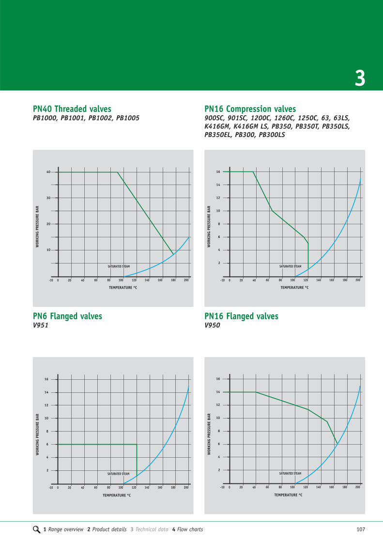
1 Range overview 2 Product details 3 Technical data 4 Flow charts 107
3PN40 Threaded valvesPB1000, PB1001, PB1002, PB1005
40 80 160 2000 120-10 20 60 140 180100
10
20
30
40
SATURATED STEAM
TEMPERATURE ºC
WOR
KIN
G PR
ESSU
RE B
AR
PN16 Compression valves900SC, 901SC, 1200C, 1260C, 1250C, 63, 63LS,K416GM, K416GM LS, PB350, PB350T, PB350LS,PB350EL, PB300, PB300LS
40 80 160 2000
12
16
120
2
10
14
-10 20 60 140 180100
4
6
8
SATURATED STEAM
TEMPERATURE ºC
WOR
KIN
G PR
ESSU
RE B
AR
PN6 Flanged valvesV951
TEMPERATURE ºC
40 80 160 2000
12
16
120
2
10
14
-10 20 60 140 180100
WOR
KIN
G PR
ESSU
RE B
AR
4
6
8
SATURATED STEAM
PN16 Flanged valvesV950
TEMPERATURE ºC
40 80 160 2000
12
16
120
2
10
14
-10 20 60 140 180100
WOR
KIN
G PR
ESSU
RE B
AR
4
6
8
SATURATED STEAM

108 1 Range overview 2 Product details 3 Technical data 4 Flow charts
Technical dataPressure and temperature ratings
PN16 Flanged valvesV952, V952V, 906, 906G, 905, 905G, 900XS,901XS, 900RM, V914, V909, V911, V912
TEMPERATURE ºC
40 80 160 2000
12
16
120
2
10
14
-10 20 60 140 180100
WOR
KIN
G PR
ESSU
RE B
AR
4
6
8
SATURATED STEAM
PN16 Flanged valvesV953
40 80 160 2000
12
16
120
2
10
14
-10 20 60 140 180100
4
6
8
SATURATED STEAM
TEMPERATURE ºC
WOR
KIN
G PR
ESSU
RE B
AR
PN16 Flanged valvesPB1006
40 80 160 2000 120-10 20 60 140 180100
10
20
30
40
SATURATED STEAM
TEMPERATURE ºC
WOR
KIN
G PR
ESSU
RE B
AR
PN25 Weld valvesPB1003, PB1004
40 80 160 2000 120-10 20 60 140 180100
10
20
30
40
SATURATED STEAM
TEMPERATURE ºC
WOR
KIN
G PR
ESSU
RE B
AR

1 Range overview 2 Product details 3 Technical data 4 Flow charts 109
3Technical dataTechnical suitability
Ballorex Venturi dynamic valvesVALVE SUITABILITY
Steam Water Oil Air Gas Gas Gas GasProduct Inert Combustible† Corrosive†† Oxygen
PS902S, 902S, PT902S, XT902 � � � � � � � �
Ballorex Venturi commissioning valvesVALVE SUITABILITY
Steam Water Oil Air Gas Gas Gas GasProduct Inert Combustible† Corrosive†† Oxygen
PS900S, PT900S, 900S, � � � � � � � �
900SC, 900XS, XT900
†The valves are suitable for British Gas Applications Family Gases 1, 2 and 3. ††Suitable in applications where moisture is completely absent
VALVE SUITABILITY
Steam Water Oil Air Gas Gas Gas GasProduct Inert Combustible† Corrosive†† Oxygen
PS901S, PT901S, 901S, � � � � � � � �
901SC, 901XS, XT901
VALVE SUITABILITY
Steam Water Oil Air Gas Gas Gas GasProduct Inert Combustible† Corrosive†† Oxygen
PS1260, 1260, 1260C, PS1250,
1250C, 900RM, V953, � � � � � � � �
PT1250, XT1260, XT1250, V952V
Ballorex Venturi double regulating valves
Commissioning valves and metering stations
Double regulating valvesVALVE SUITABILITY
Steam Water Oil Air Gas Gas Gas GasProduct Inert Combustible† Corrosive†† Oxygen
PS1200, 1200, 1200C, XT1200, V952 � � � � � � � �

110 1 Range overview 2 Product details 3 Technical data 4 Flow charts
Technical dataTechnical suitability
Circulation valves
†The valves are suitable for British Gas Applications Family Gases 1, 2 and 3. ††Suitable in applications where moisture is completely absent
*Air to maximum 10bar.
VALVE SUITABILITY
Steam Water Oil Air Gas Gas Gas GasProduct Inert Combustible† Corrosive†† Oxygen
PB1000, PB1001, PB1002, � � � � � � � �
PB1003, PB1004
Ballomax steel ball valves
VALVE SUITABILITY
Steam Water Oil Air Gas Gas Gas GasProduct Inert Combustible† Corrosive†† Oxygen
P603, P605, P604, P606 � � � � � � � �
Gate valvesVALVE SUITABILITY
Steam Water Oil Air Gas Gas Gas GasProduct Inert Combustible† Corrosive†† Oxygen
1072, 1070/125, 63, 63LS � � � � � � � �
Quarter turn ball valvesVALVE SUITABILITY
Steam Water Oil Air* Gas Gas Gas GasProduct Inert Combustible† Corrosive†† Oxygen
PB700, PB700T, PB500 Yellow,
PB300 Yellow, PB300T Yellow, � � � � � � � �
PB300 Green, PB300T Green
PS500, PT500, PS550, PS550EL,
PT550, PS550T, PT550T, XT500, � � � � � � � �
XT550, XT550EL
PB500T, PB550DR, PB550DR T,
PB550DR LS, PB560, PB560EXT,
PB500EL, PB550EL, PB350EL, � � � � � � � �
PB350, PB350T, PB350LS,
PB300 Red, PB300 Blue,
PB300T Red, PB300T Blue
PB100 � � � � � � � �
PB50HU, PB50, PB52HU, 1111BV � � � � � � � �

1 Range overview 2 Product details 3 Technical data 4 Flow charts 111
3
Globe valves
Gate valves – continuedVALVE SUITABILITY
Steam Water Oil Air Gas Gas Gas GasProduct Inert Combustible† Corrosive†† Oxygen
PS1070/125, PT1070/125,
PS1070/125LS, PT1070/125LS,
PS1078, PT1078, PS1078LS, � � � � � � � �
PT1078LS, PS1068, PT1068,
V951, V950, XT1068, XT1068LS
1070/125LS, 1078, 1078LS, 1068LS,� � � � � � � �
K416GM, K416GMLS
1068 � � � � � � � �
1065 � � � � � � � �
Check valvesVALVE SUITABILITY
Steam Water Oil Air* Gas Gas Gas GasProduct Inert Combustible† Corrosive†† Oxygen
PS1060A, PT1060A, K424, K4426
K4424, K4424CP, V914, V909, � � � � � � � �
V911, V912,
1060A, 1039, � � � � � � � �
1063, 1064 � � � � � � � �
0015YA, 0015ZA � � � � � � � �
VALVE SUITABILITY
Steam Water Oil Air Gas Gas Gas GasProduct Inert Combustible† Corrosive†† Oxygen
1029 � � � � � � � �
1031 � � � � � � � �
*Air to maximum 5bar.

112 1 Range overview 2 Product details 3 Technical data 4 Flow charts
Technical dataTechnical suitability
†The valves are suitable for British Gas Applications Family Gases 1, 2 and 3. ††Suitable in applications where moisture is completely absent
Ballofix isolating ball valvesVALVE SUITABILITY
Steam Water Oil Air Gas Gas Gas GasProduct Inert Combustible† Corrosive†† Oxygen
3390ZA, 3205YA, 3305YA, 3405YA,
3505YA, 3205ZA, 3250ZA, 3350ZA,
3405ZA, 3200YA, 3210YA, 3310YA,
3410YA, 3510YA, 3200ZA, 3310ZA, � � � � � � � �
3410ZA, 3510ZA, 3310YP, 3310ZP
5035CA, 5060BA, 5045CA, 5095CA,
5095BA, 3381YA
33504BGA � � � � � � � �
3481YA, 3581YA, 4381ZA, 4481ZA,
6381ZA, 6481ZA, 3381ZA, 3481ZA,
3581ZA, 4381ZP, 6381ZP, 6481ZP,
3381YP, 3481YP, 3381ZM, 3381ZP, � � � � � � � �
3331YA, 3431YA, 3331ZA, 3331YP,
3331ZP, 3375YA, 3380YA, 3380ZA,
3380YP, 3380ZP, 1581YA, 1581ZA
Drain cocksVALVE SUITABILITY
Steam Water Oil Air Gas Gas Gas GasProduct Inert Combustible† Corrosive†† Oxygen
1832, 833GM � � � � � � � �
833GM LS � � � � � � � �
PB60HU � � � � � � � �
StrainersVALVE SUITABILITY
Steam Water Oil Air Gas Gas Gas GasProduct Inert Combustible† Corrosive†† Oxygen
V954, PS913, PT913, V913, PS954 � � � � � � � �

1 Range overview 2 Product details 3 Technical data 4 Flow charts 113
3Ballofix compression filter valves
VALVE SUITABILITY
Steam Water Oil Air Gas Gas Gas GasProduct Inert Combustible† Corrosive†† Oxygen
33615ZA, 34622ZA, 33615ZP, � � � � � � � �
5035CA
Ballofix service valvesVALVE SUITABILITY
Steam Water Oil Air Gas Gas Gas GasProduct Inert Combustible† Corrosive†† Oxygen
3140YA, 3140ZA, 3140ZP, 3160YA, � � � � � � � �
3160ZA
Butterfly valvesVALVE SUITABILITY
Steam Water Oil Air Gas Gas Gas GasProduct Inert Combustible† Corrosive†† Oxygen
V906, V906G, V905, V905G � � � � � � � �
V907, V907G, � � � � � � � �
Ball valveVALVE SUITABILITY
Steam Water Oil Air Gas Gas Gas GasProduct Inert Combustible† Corrosive†† Oxygen
TX490L � � � � � � � �
Automatic air ventVALVE SUITABILITY
Steam Water Oil Air Gas Gas Gas GasProduct Inert Combustible† Corrosive†† Oxygen
775 � � � � � � � �

114 1 Range overview 2 Product details 3 Technical data 4 Flow charts
Technical dataTechnical suitability
†The valves are suitable for British Gas Applications Family Gases 1, 2 and 3. ††Suitable in applications where moisture is completely absent
Ballomax ball valvesVALVE SUITABILITY
Steam Water Oil Air Gas Gas Gas GasProduct Inert Combustible† Corrosive†† Oxygen
PB1005, PB1006 � � � � � � � �
Where indicated Pegler valves are suitablefor use with water, steam, oil and certaingases. It is common practice for manufac-turers to claim that their valves are suitablewith gas. In fact, gases vary widely intheir properties and the followingexplanation is offered for guidance.
Gases may be classified as follows:
Class 1. INERTAir, argon, carbon dioxide, helium, nitrogen
Class 2. COMBUSTIBLEHydrogen, methane, natural gas, town gas
Class 3. CORROSIVEChlorine, sulphur dioxide
Class 4. OXYGEN
Gas applications
Class 1. INERTEntirely suitable. We recommend therenewable disk valves for preference. When ordering please state the specificpurpose for which the valve is required.
Class 2. COMBUSTIBLEThere is no technical reason why our valvesshould not be used. However, in view ofthe hazards involved and the specialrequirements and approvals required byBritish Gas, we do not make any generalrecommendation for this class of gas unlessspecified, but will be pleased to discussspecific applications.
Class 3. CORROSIVECopper alloy valves are only suitable forsuch application if moisture is completelyabsent.
Class 4. OXYGENOxygen can react dangerously with oils and greases, and normal lubricants cannotbe used so brass/bronze valves are notrecommended for this use.
The suitability of Pegler Yorkshire valvesfor handling different classes of gas

1 Range overview 2 Product details 3 Technical data 4 Flow charts 115
3Technical dataMaterials specification
Ballorex Venturi dynamic valves
Ballorex Venturi commissioning valves
Double regulating valves
COMPONENT PS902S, PT902S, 902S, XT902
Body DZR brass
Spindle DZR brass
Venturi DZR brass
End connection Gunmetal body (PS902S)
End connection ‘O’ ring EPDM (PS902S)
Ballorex Venturi double regulating valvesCOMPONENT PS901S, PT901S, 901S, 901SC, 901XS, XT901
Body DZR brass
Spindle DZR brass
Ball adjusting screw DZR brass, chrome plated
Gaskets PTFE
‘O’ rings EPDM
Handle Polyamide
End connection Gunmetal body (PS901S)
End connection ‘O’ ring EPDM (PS901S)
End connection DZR brass body (PT901S)
End connection ‘O’ ring EPDM (PT901S)
Grab ring Stainless steel, SS316 (PT901S)
Compression nut Forged brass, chrome plated (901SC)
Compression cone Brass (901SC)
Ballorex Venturi double regulating valvesCOMPONENT 901XS
Body Cast iron, fully lugged
Venturi pipe Carbon steel
Measuring P/T plug DZR brass
Rubber in P/T plug EPDM
Disc Stainless steel
Shaft Stainless steel
Backing ring EPDM
Drive pin Stainless steel
Shaft seal NBR 1
Bearing Lubricated bronze
End connection Gunmetal body (PS1200)
End connection ‘O’ ring EPDM (PS1200)
Compression nut Forged brass, chrome plated (1200SC)
Compression cone Brass (1200SC)
Ballorex Venturi commissioning valvesCOMPONENT 900XS
Body Cast iron, fully lugged
Disc Stainless steel
Shaft Stainless steel
Backing ring EPDM
Drive pin Stainless steel
Shaft seal NBR 1
Bearing Lubricated gunmetal
COMPONENT V952, V952V
Body Ductile iron
Bonnet Ductile iron
Disc Ductile iron, EPDM Coated
Disc nail Brass
‘O’ ring EPDM
Stem Stainless steel
Gasket Graphite
Handwheel Carbon steel (50-100)
Handwheel Ductile iron (125-200)
Test point DZR Brass (V952V)
COMPONENT PS900S, PT900S, 900S, 900SC, XT900
Body DZR brass
Spindle DZR brass
Venturi, ball, needle DZR brass, chrome plated
Seals PTFE
‘O’ rings EPDM
Handle Polyamide
Measuring P/T plug DZR brass
End connection Gunmetal body (PS900S)
End connection ‘O’ ring EPDM (PS900S)
End connection DZR brass body (PT900S)
End connection ‘O’ ring EPDM (PT900S)
Grab ring Stainless steel, SS316 (PT900S)
Compression nut Forged brass, chrome plated (900SC)
Compression cone Brass (900SC)

116 1 Range overview 2 Product details 3 Technical data 4 Flow charts
Technical dataMaterials specification
Double regulating valves
Metering stations
COMPONENT PS1200, 1200, 1200C, XT1200
Body GDCBr. BSEN 1982, CC 752S
Bonnet EBB. BSEN 12164, CW 617N
Spindle EBB. BSEN 12164, CW 617N
Disc EBB. BSEN 12164, CW 617N
Gland Packing Piece EBB, BSEN 12164, CW 617N
‘O’ rings EPTO
Circlip Carbon spring steel
Adjustment screw EBB. BSEN 12164, CW 617N
Seals EPTO
Handle 30% Glass filled nylon 66
Set screw Brass
End connection Gunmetal body (PS1200)
End connection ‘O’ ring EPDM (PS1200)
Compression nut Forged brass (1200SC)
Compression cone Brass (1200SC)
COMPONENT PS1250, PT1250, 1250, 1250C, XT1250
Body GDCBr. BSEN 1982, CC 752S
Test point DZR brass
Seals EPDM
Orifice plate
End connection Gunmetal body (PS1250)
End connection ‘O’ ring EPDM (PS1250)
End connection DZR brass body (PT1250)
End connection ‘O’ ring EPDM (PT1250)
Grab ring Stainless steel, SS316 (PT1250)
Compression nut Forged brass, chrome plated (1250C)
Compression cone Brass (1250C)
Commissioning valvesCOMPONENT PS1260, 1260, 1260C, XT1260
Body GDCBr. BSEN 1982, CC 752S
Bonnet EBB. BSEN 12164, CW 617N
Spindle EBB. BSEN 12164, CW 617N
Disc EBB. BSEN 12164, CW 617N
Gland Packing Piece EBB. BSEN 12164, CW 617N
‘O’ rings EPTO
Orifice plate EBB. BSEN 12164, CW 617N
Circlip Carbon spring steel
Adjustment screw EBB. BSEN 12164, CW 617N
Test points DZR brass
Seals EPTO
Handle 30% Glass filled nylon 66
Set screw Brass
End connection Gunmetal body (PS1260)
End connection ‘O’ ring EPDM (PS1260)
Compression nut Forged brass (1260C)
Compression cone Brass (1260C)
COMPONENT V953
Body Stainless steel
Test point DZR brass
Extension Stainless steel
Stainless steel metering station
Steel metering stationsCOMPONENT Venturi cast iron metering stations
Body Cast iron
Venturi Carbon steel
Test points DZR brass
Seal and cap seal EPDM

1 Range overview 2 Product details 3 Technical data 4 Flow charts 117
3
Circulation valvesCOMPONENT P603, P605, P604, P606
Body Gunmetal
Valve washer EPM/PTFE
Adjuster EPP, B2
Thermal actuator Gunmetal
Drain valve body Gunmetal
Valve outlet Gunmetal
COMPONENT PB560, PB560EXT
Body DZR brass
Tee handle Aluminium, painted
Strainer mesh Stainless steel
Exterior sleeve PA6.6 - 20% GF
Securing screws Iron, chrome plated
Stem extension CW614N
Ball Brass, chrome plated
Stem DZR brass
‘O’ ring EPDM
Ball seat PTFE (Teflon)
Quarter turn ball valvesQuarter turn ball valves
Quarter turn ball valvesCOMPONENT PS500, PT500, PB500, PS500T, PT500T,
PB500EL, PB500T, XT500
Body Forged brass, chrome plated (1/4" to 2")
Gravity die cast brass, chrome plated (21/2" to 4")
End piece Forged brass, chrome plated (1/4" to 2")
Gravity die cast brass, chrome plated (21/2" to 4")
Ball Brass bar, chrome plated (1/4" to 1/2")
Forged brass, chrome plated (3/4" to 2")
Gravity die cast brass, chrome plated (21/2" to 4")
Stem Brass bar
Seats PTFE (Teflon)
Thrust washer PTFE (Teflon)
Stem ‘O’ ring Viton
Lever handle High temperature PVC insulated zinc plated steel
Nut (self locking) Zinc plated steel
Tee handle Aluminium, painted
Security screws Nickel plated brass
End connection Gunmetal body (PS500/PS500T) (15 to 54) (15 to 28)
End connection ‘O’ ring EPDM (PS500/PS500T) (15 to 54) (15 to 28)
End connection DZR brass body (PT500/PT500T) (15 to 54) (15 to 28)
End connection ‘O’ ring EPDM (PT500/PT500T) (15 to 54) (15 to 28)
Grab ring Stainless steel, SS316
(PT500/PT500T) (15 to 54) (15 to 28)
Sleeve Brass (EL)
Ext Stem Brass (EL)
Fixing screw Steel (EL)
Washer Brass (EL)
COMPONENT PS550, PS550T, PT550, PT550T, XT550, PS550EL, XT550EL
Body DZR brass
Ball Brass, chrome plated
Seat/thrust washer PTFE (Teflon)
Stem ‘O’ ring Viton
Lever handle High temperature PVC insulated
Nut (self locking) Zinc plated steel
Tee handle Aluminium, painted
Security screws Nickel plated brass
Stem DZR brass
End connection Gunmetal body (PS550/PS550T) (15 to 54) (15 to 28)
End connection ‘O’ ring EPDM (PS550/PS550T) (15 to 54) (15 to 28)
End connection DZR brass body (PT550/PT550T) (15 to 54) (15 to 28)
End connection ‘O’ ring EPDM (PT550/PT550T) (15 to 54) (15 to 28)
Grab ring Stainless steel, SS316
(PT550/PT550T) (15 to 54) (15 to 28)
Sleeve Brass (EL)
Ext Stem Brass (EL)
Fixing screw Steel (EL)
Washer Brass (EL)
Quarter turn ball valvesCOMPONENT PB700, PB700T
Body Forged brass, chrome plated (1/4" to 2")
Gravity die cast brass, chrome plated (21/2" to 4")
End piece Forged brass, chrome plated (1/4" to 2")
Gravity die cast brass, chrome plated (21/2" to 4")
Ball Brass bar, chrome plated (1/4" to 1/2")
Forged brass, chrome plated (3/4" to 2")
Gravity die cast brass, chrome plated (21/2" to 4")
Stem Brass bar
Seats PTFE (Teflon)
Thrust washer PTFE (Teflon)
Stem ‘O’ ring Viton
Lever handle High temperature PVC insulated zinc plated steel
Nut (self locking) Zinc plated steel
Tee handle Aluminium, painted
Security screws Nickel plated brass

118 1 Range overview 2 Product details 3 Technical data 4 Flow charts
Technical dataMaterials specification
COMPONENT PB300, PB300T
Body Forged brass, chrome plated
End piece Forged brass, chrome plated
Ball Brass bar, chrome plated (15mm)
Forged brass, chrome plated (22 to 54mm)
Stem Brass bar
Seats PTFE (Teflon)
Stem ‘O’ ring Viton
Lever handle High temperature PVC insulated zinc plated steel
Nut (self locking) Zinc plated steel
Tee handle Aluminium, painted
Security screws Nickel plated brass
Compression nut Forged brass, chrome plated
Compression cone Brass
Quarter turn ball valves
COMPONENT PB50, PB50HU, PB52HU
Body Brass, chrome plated
Cap Brass, chrome plated
Ball Brass, chrome plated
Ball seal PTFE (Teflon)
Spindle Brass, chrome plated
Spindle seal NBR
Hose pipe Brass, chrome plated
Hose nut Brass, chrome plated
Hose union ‘O’ ring NBR
Lever Steel (PB50HU, PB50)
Cast aluminium, painted black (PB52HU)
Lever nut Brass
Lever securing screw Brass, chrome plated
Lever grip PVC
Gland nut Brass, chrome plated
Flow straightener Polyethylene
Quarter turn ball valves
Quarter turn ball valves
Quarter turn ball valves
COMPONENT PB350, PB350T, PB350LS, PB350EL
Body DZR brass
Ball Brass, chrome plated
Stem Brass
Stem ‘O’ ring Viton
Seat rings PTFE (Teflon)
Lever handle Steel
Lever nut self locking Zinc plated steel
Tee handle Aluminium, painted (PB550DR T)
Tee handle security screw Nickel plated brass
Lockshield cap Plastic
Lockshield Brass
Lockshield security screw Brass
Compression nut Brass
Compression cone Brass
Sleeve Brass (EL)
Ext Stem Brass (EL)
Fixing screw Steel (EL)
Washer Brass (EL)
COMPONENT PB550DR, PB550DR T, PB550DR LS, PB550EL
Body DZR brass
Ball Brass, chrome plated
Stem DZR brass
Stem ‘O’ ring Viton
Seat rings PTFE (Teflon)
Lever handle Steel
Tee handle Aluminium, painted (PB550DR T)
Lever nut self locking Zinc plated steel
Tee handle security screw Nickel plated brass
Lockshield dust cap Plastic (PB550DR LS)
Lockshield Brass
Lockshield security screw Brass
Sleeve Brass (EL)
Ext Stem Brass (EL)
Fixing screw Steel (EL)
Washer Brass (EL)

1 Range overview 2 Product details 3 Technical data 4 Flow charts 119
3
COMPONENT 1111BV
Body Forged brass, nickel plated
Body cap Forged brass, nickel plated
Ball Forged brass, chrome plated
Ball seal PTFE
Stem Brass, nickel plated
Lever Steel, PVC coated
Nut Steel, nickel plated
Quarter turn ball valves
Quarter turn ball valves
COMPONENT PB1000, PB1001, PB1002, PB1003, PB1004
Body Steel
Ball Stainless steel
Seat PTFE
Friction packing PTFE, 20% C
‘O’ ring EPDM, viton
Female end Steel
Back up spring Spring steel
Back up ring Stainless steel
Neck ring, handle Steel
Intermediate ring Stainless steel
Stop pin Steel hardened
Cap nut Steel
Spindle guide Steel
Spindle Stainless steel
Ballomax steel ball valves
COMPONENT PB100
Body Forged brass, chrome plated
End piece Forged brass, chrome plated
Ball Brass, chrome plated
Stem Brass
Seats PTFE
Lever handle Dip-coated on CP steel
Handle nut Steel
Friction washer PTFE
‘O’ rings Nitrile rubber
COMPONENT 1072
Body Gunmetal
Bonnet Gunmetal
Stem Gunmetal
Wedge Gunmetal
Stem ring Gunmetal
Gland Brass bar
Gland nut Brass bar
Handwheel Aluminium
Handwheel nut Brass bar
Gland packing PTFE
Rating disc Aluminium
Gate valves
COMPONENT PS1070/125, PT1070/125, 1070/125
Body Gunmetal
Bonnet Forged brass (1/4" to 3")
Gravity die cast brass (4")
Stem Brass bar
Wedge Brass
Stem ring Brass bar
Gland Brass bar
Gland Nut Brass bar (1/4" to 1")
Forged brass (11/4" to 4")
Handwheel Aluminium
Handwheel nut Brass bar
Gland packing PTFE
Rating disc Aluminium
End connection Gunmetal body (PS1070/125) (15 to 54)
End connection ‘O’ ring EPDM (PS1070/125) (15 to 54)
End connection DZR brass body (PT1070/125) (15 to 54)
End connection ‘O’ ring EPDM (PT1070/125) (15 to 54)
Grab ring Stainless steel SS316 (PT1070/125) (15 to 54)
Gate valves

COMPONENT PS1068, PS1068LS, PT1068, PT1068LS,1068, 1068LS, XT1068, XT1068LS
120 1 Range overview 2 Product details 3 Technical data 4 Flow charts
Technical dataMaterials specification
COMPONENT PS1070/125LS,PT1070/125LS, 1070/125LS
Body Gunmetal
Bonnet Forged brass (1/4" to 3")
Gravity die cast brass (4")
Stem Brass bar
Wedge Brass
Stem ring Brass bar
Gland Brass bar
Gland Nut Brass bar (1/4" to 1")
Forged brass (11/4" to 4")
Handwheel Aluminium
Handwheel nut Brass bar
Gland packing PTFE
Rating disc Aluminium
Lockshield Brass
End connection Gunmetal body
(PS1070/125, PS1070/125 LS) (15 to 54)
End connection ‘O’ ring EPDM (PS1070/125, PS1070/125 LS) (15 to 54)
End connection DZR brass body
(PT1070/125, PT1070/125 LS) (15 to 54)
End connection ‘O’ ring EPDM (PT1070/125, PT1070/125 LS) (15 to 54)
Grab ring Stainless steel SS316
(PT1070/125, PT1070/125 LS) (15 to 54)
COMPONENT PS1078, 1078, PS1078LS, 1078LS
Body DZR brass
Bonnet DZR brass
Stem DZR brass
Wedge DZR brass
Stem ring DZR brass
Gland Brass bar
Gland Nut Brass bar
Handwheel Aluminium
Handwheel nut Brass
Gland packing PTFE
Rating disc Aluminium
Lockshield Brass
End connection Gunmetal body (PS1078, PS1078LS)
End connection ‘O’ ring EPDM (PS1078, PS1078LS)
Body Forged brass (1/4" to 2")
Gravity die cast brass (21/2" to 4")
Bonnet Forged brass (1/4" to 3")
Gravity die cast brass (4")
Stem Brass bar
Wedge Forged brass (1/4" to 21/2")
Gravity die cast brass (3" & 4")
Stem ring Brass bar
Gland Brass bar
Gland nut Brass bar (1/4" to 1")
Forged brass (11/4" to 4")
Handwheel Aluminium
Handwheel nut Brass bar
Gland packing PTFE
Rating disc Aluminium
Lockshield Brass bar
End connection Gunmetal body (PS500/PS500T) (15 to 54) (15 to 58)
End connection ‘O’ ring EPDM (PS500/PS500T) (15 to 54) (15 to 58)
End connection DZR brass body (PT500/PT500T) (15 to 54) (15 to 58)
End connection ‘O’ ring EPDM (PT500/PT500T) (15 to 54) (15 to 58)
Grab ring Stainless steel SS316
(PT500/PT500T) (15 to 54) (15 to 58)
Gate valves
Gate valves Gate valves
Gate valvesCOMPONENT 1065
Body Forged brass
Bonnet Forged brass
Stem Brass bar
Wedge Forged brass
Gland nut Brass bar
Handwheel Aluminium
Handwheel nut Brass bar
Rating disc Aluminium
‘O’ rings Nitrile rubber

1 Range overview 2 Product details 3 Technical data 4 Flow charts 121
3Gate valvesCOMPONENT 63, 63LS
Body Forged brass
Bonnet Forged brass
Stem Brass bar
Wedge Brass
Stem ring Brass bar
Gland Brass bar
Gland nut Brass bar (15 and 22mm)
Forged brass (28 to 54mm)
Handwheel Aluminium
Handwheel nut Brass bar
Rating disc Aluminium
Lockshield Brass bar (Prestex 63LS)
Compression nut Forged brass, chrome plated
Compression cone Brass
Gate valves
Gate valves
COMPONENT K416GM, K416GMLS
Body Gunmetal
Bonnet Gunmetal
Stem Gunmetal
Gland nuts Brass
Gland Brass
Packing flange and bolts Gunmetal
Handwheel Aluminium
Nameplate Aluminium
Handle screw Steel
Compression nut Brass
Compression cone Brass
COMPONENT V951
Body Cast iron
Bonnet Cast iron
Bonnet gasket EPDM
Stem Steel
Wedge Cast iron
Wedge nut Brass
Gland packing Brass
Gland follower Ductile iron
Packing Graphite non asbestos
Stuffing box Cast iron
Stuffing box gasket Graphite non asbestos
Handwheel Cast iron
Yoke joint Cast iron
Yoke sleeve Gunmetal
Gate valvesCOMPONENT V950
Body Ductile iron
Body seat ring Gunmetal
Bonnet Ductile iron
Bonnet gasket EPDM
Stem Stainless steel
Wedge Ductile iron
Wedge trim Gunmetal
Wedge nut Gunmetal
Gland flange Ductile iron
Gland Ductile iron
Gland packing Graphite non asbestos
Stuffing box Ductile iron
Stuffing box gasket Compressed graphite
Handwheel Ductile iron

122 1 Range overview 2 Product details 3 Technical data 4 Flow charts
COMPONENT 1029
Body Gunmetal
Bonnet Forged brass
Stem Brass bar
Disk holder Brass bar
Disk ring Brass bar
Disk Glass filled PTFE
Disk nut Brass bar
Gland Brass bar
Gland nut Brass bar
Packing PTFE
Handwheel Aluminium
Handwheel nut Brass bar
Rating disc Aluminium
COMPONENT 1031
Body Gunmetal
Bonnet Forged brass
Stem Brass bar
Disk ring Brass bar
Disk Brass bar
Gland Brass bar
Gland nut Brass bar
Packing PTFE
Handwheel Aluminium
Handwheel nut Brass bar
Rating disc Aluminium
COMPONENT PS1060A, PT1060A, 1060A
Body Gunmetal
Cap Forged brass (1/4" to 2")
Gunmetal (21/2" to 4")
Valve Gunmetal
Swinger Brass bar (1/4" to 1")
Gunmetal (11/4" to 4")
Swinger pin Brass bar
Swinger pin cap Brass bar (21/2" to 4")
Nut Brass bar
Rating disc Tinned iron sheet
End connection Gunmetal body (PS1060A) (15 to 54)
End connection ‘O’ ring EPDM (PS1060A) (15 to 54)
End connection DZR brass body (PT1060A) (15 to 54)
End connection ‘O’ ring EPDM (PT1060A) (15 to 54)
Grab ring Stainless steel, SS316 (PT1060A) (15 to 54)
Globe valves
Globe valves Check valves
Check valvesCOMPONENT 1039
Body Gunmetal
Cap Forged brass
Valve Brass bar
Rating Disc Aluminium
Check valvesCOMPONENT 1062
Body Forged brass (1/2" to 3/4")
Gravity die cast brass (1")
Cap Forged brass
Swinger Brass bar
Swinger pin Brass bar
Bush Brass bar
Valve Brass bar
Nut Brass bar
Rating disc Aluminium
Technical dataMaterials specification

1 Range overview 2 Product details 3 Technical data 4 Flow charts 123
3Check valves
Check valves
COMPONENT 1063
Body Brass
Pin ABS
Pin washer ABS
Sealing washer EPDM
Spring Stainless steel
COMPONENT 0015YA, 0015ZA
Body DZR brass
Ball Nickel plated DZR brass
‘O’ Rings EPDM
Compression nut Brass
Compression cone Brass
Check valves
Check valves
Check valves
Check valves
COMPONENT K424
Body DZR brass
Non-return valve Nylon
Circlip Stainless steel
Washer DZR brass
Compression nut Brass
Compression ring Brass
COMPONENT K4426
Body DZR brass
Test plug DZR brass
Non-return valve Nylon
Test plug seal ‘O’ ring WRAS approved elastnor
Circlip Stainless steel
Washer DZR copper alloy
COMPONENT K4424, K4424CP
Body DZR brass, chrome plated
Check valve Nylon
Test plug DZR brass
Test plug seal ‘O’ ring WRAS approved elastnor
Circlip Stainless steel
Washer DZR Brass
Compression nut Brass, chrome plated
Compression ring Brass
COMPONENT 1064
Body Brass
Pin ABS
Pin washer ABS
Sealing washer EPDM
Spring Stainless steel
Filter Stainless steel
Filter/body connection ABS
Check valvesCOMPONENT V914
Body Cast iron
Body seating Gunmetal
Disc Cast iron
Disc assembly Cast iron
Disk facing ring Gunmetal
Disc nut Brass
Cover Cast iron
Cover gasket Graphite non asbestos
Hinge pin Stainless steel
Hinge pin plug Brass
Hinge Ductile iron
Stop pin Stainless steel
Seat EPDM
Seat ring Gunmetal
Gasket Asbestos free
Springs Stainless steel
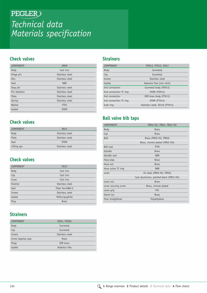
124 1 Range overview 2 Product details 3 Technical data 4 Flow charts
Technical dataMaterials specification
Check valves
Check valves
Check valves
COMPONENT V909
Body Cast iron
Hinge pin Stainless steel
Disc Stainless steel
Seat NBR
Stop pin Stainless steel
Pin retainers Stainless steel
Plate Stainless steel
Spring Stainless steel
Washer PTFE
Gasket EPDM
COMPONENT V911
Body Stainless steel
Plate Stainless steel
Seal EPDM
Lifting eye Stainless steel
COMPONENT V912
Body Cast iron
Cap Cast iron
Cover Cast iron
Strainer Stainless steel
Seal Fibre TesnitBA-U
Screen Stainless steel
Gasket Teflon/graphite
Plug Brass
COMPONENT V954, PS954
Body Gunmetal
Cap Gunmetal
Screen Stainless steel
Screw tapping caps Brass
Plugs DZR brass
Gasket Asbestos free
COMPONENT PS913, PT913, V913
Body Gunmetal
Cap Gunmetal
Screen Stainless steel
Gasket Asbestos free (non stick)
End connection Gunmetal body (PS913)
End connection ‘O’ ring EPDM (PS913)
End connection DZR brass body (PT913)
End connection ‘O’ ring EPDM (PT913)
Grab ring Stainless steel, SS316 (PT913)
Strainers
Strainers
COMPONENT PB50 HU, PB50, PB52 HU
Body Brass
Cap Brass
Ball Brass (PB50 HU, PB50)
Brass, chrome plated (PB52 HU)
Ball seal PTFE
Spindle Brass
Spindle seal NBR
Hose pipe Brass
Hose nut Brass
Hose union ‘O’ ring NBR
Lever A3 steel (PB50 HU, PB50)
Cast aluminium, painted black (PB52 HU)
Lever nut Brass
Lever securing screw Brass, chrome plated
Lever grip PVC
Gland nut Brass
Flow straightener Polyethylene
Ball valve bib taps

1 Range overview 2 Product details 3 Technical data 4 Flow charts 125
3
COMPONENT 1832
Body Gunmetal
Plug Gunmetal
Gland Brass bar (1/2" and 3/4")
Forged brass (1")
Bolt Brass bar
Gland Packing PTFE
Lever Cast iron
Pipe Brass bar
Boss Brass bar (1/2")
Forged brass (3/4" and 1")
Cap Brass bar
‘O’ ring WRAS approved rubber
Washer Akulon (3/4" and 1")
Strap Nylon 6
Miscellaneous
Miscellaneous
Miscellaneous
COMPONENT PB60HU
Body DZR brass
Cap Brass bar
Hose union pipe Brass
Strap Nylon 6
Tee handle Aluminium, painted
Locking screw Brass
‘O’ ring Viton
Stem DZR brass
Ball Brass
COMPONENT 833GM, 833GMLS
Body Gunmetal
Headwork Brass
Spindle Brass
Washer EPDM
Spindle ‘O’ ring EPDM
Cap ‘O’ ring EPDM
LS cover Brass
Ballofix isolating ball valves
Ballofix isolating ball valves
Body DZR brass
Ball DZR brass, nickel plated
‘O’ Rings EPDM nitrile (33504BGA)
Compression nut Forged brass
Compression cone Brass
COMPONENT 3205YA, 3350YA, 3450YA, 3550YA, 3200YA, 3210YA, 3310YA, 3410YA, 3510YA, 5060BA, 5045CA,
33504BGA, 5095CA, 5095BA, 3381YA, 3481YA,3581YA, 3331YA, 3431YA, 3375YA, 3380YA, 1581YA
Body DZR brass, chrome plated
Ball DZR brass, nickel plated
‘O’ rings EPDM
Handle Nylon PA6.6 (30% glass reinforced)
Compression nut Forged brass, chrome plated
Compression cone Brass
COMPONENT 3390ZA, 3205ZA, 3250ZA, 3350ZA, 3450ZA, 3200ZA, 3310ZA, 3410ZA, 3510ZA, 4381ZA, 4481ZA, 6381ZA, 6481ZA, 3381ZA, 3481ZA, 3581ZA,
3331ZA, 3380ZA, 1581ZA
Ballofix isolating ball valves
Ballofix isolating ball valvesCOMPONENT 4381ZP, 6381ZP, 3381ZM, 3381ZP, 3331ZP, 3380ZP
Body DZR brass, chrome plated
Ball DZR brass, nickel plated
‘O’ rings EPDM
Handle Nylon PA6.6 (30% glass reinforced)
Compression nut Forged brass, chrome plated
Compression cone Brass
COMPONENT 3381YP, 3481YP, 3381YP, 3331YP, 3380YP
Body DZR brass
Ball DZR brass, nickel plated
‘O’ rings EPDM
Compression nut Forged Brass
Compression cone Brass

126 1 Range overview 2 Product details 3 Technical data 4 Flow charts
Technical dataMaterials specification
COMPONENT 3140YA, 3160YA
Body DZR brass
Ball DZR brass, nickel plated
‘O’ rings EPDM
Compression nut Forged brass
Compression cone Brass
COMPONENT 3140ZA, 3160ZA
Body DZR brass, chrome plated
Ball DZR brass, nickel plated
‘O’ rings EPDM
Compression nut Forged brass, chrome plated
Compression cone Brass
Ballofix service valves
Ballofix service valves
COMPONENT 33615ZP
Body DZR brass, chrome plated
Ball DZR brass, nickel plated
‘O’ rings EPDM
Handle Nylon PA6.6 (30% glass reinforced)
Compression nut Forged brass, chrome plated
Compression cone Brass
Ballofix service valves
Ballofix filter valves
Ballofix filter valves
COMPONENT 3140ZP
Body DZR brass, chrome plated
Ball DZR brass, nickel plated
‘O’ rings EPDM
Handle Nylon PA6.6 (30% glass reinforced)
Compression nut Forged brass, chrome plated
Compression cone Brass
COMPONENT 33615ZA, 346227ZA, 5035CA
Body DZR brass, chrome plated
Ball DZR brass, nickel plated
‘O’ rings EPDM
Compression nut Forged brass, chrome plated
Compression cone Brass
Ball valveCOMPONENT TX490L
Body DZR brass, chrome plated
Ball Brass ball, chrome plated
Lever Steel PVC covered
Lever nut Steel
Ball seal PTFE
End connection DZR brass, chrome plated
End connection ‘O’ ring EPDM
Grab ring Stainless steel, SS316
Automatic air vent
Butterfly valves
COMPONENT 775
Body Brass
Float Polypropylene
Big cap Brass
‘0’ ring 1 NBR
Plastic bonnet Polyacetalic
End cap Brass
Rubber seal NBR
Spring link Stainless steel, SS302
Plastic disc Polyacetalic
‘0’ ring 2 NBR 70 shore
Check valve body Brass
Spring Stainless steel, SS302
Plastic bore Polypropylene
‘0’ ring 3 NBR 70 shore
COMPONENT V907, V907G
Body Cast iron
Shaft Stainless steel
Disc Stainless steel
Bushes up to 100mm PTFE
Bushes up to 125mm Gunmetal
‘O’ ring EPDM
Liner Nitrile

1 Range overview 2 Product details 3 Technical data 4 Flow charts 127
3Butterfly valvesCOMPONENT V906, V906G, V905, V905G
Body Ductile iron
Shaft Stainless steel
Disc Stainless steel
Bushes up to 100mm PTFE
Bushes up to 125mm Gunmetal
‘O’ ring EPDM
Liner EPDM
Ballomax ball valves valvesCOMPONENT PB1005, PB1006
Body Steel
Ball Steel
Bottom Steel
Cover disc Steel
Key Steel
Back up ring Steel
Plan bearing Steel bush with PTFE
Seger circlip Spring steel
Back up ring seat packing PTFE
Spindle Steel
Spindle guide Steel
Spiral spring Steel

128 1 Range overview 2 Product details 3 Technical data 4 Flow charts
Threaded valvesEnsure that the valve is fully open duringinstallation.
Fix the threaded pipe into a vice and applysealing compound on to the male pipethreads.
Use sealing compounds that do not overpack the threads. Preferred materials arePTFE thread tape or suitable liquid/pastesealant.
Do not use hemp.
Screw the valve on to the pipe.
Use the spanner flats adjacent to thepipe joint being made. Do not use theflats at the opposite end of the valve.
Ensure that good quality, close fittingtools are used.
Avoid tightening to such an extent thatthe female end becomes permanentlydeformed.
Valves must not be over-tightened.
Use suitable hangers close to both ends of the valve in order to remove stressestransmitted by the pipe.
Compression ended valvesThe range is designed for use with coppertube to BS EN 1057:1996 (formerly BS 2871:Part 1), BS 2871:Part 2, orstainless steel tube to BS 4127:1994.
To make a joint:
Ensure that the fitting is the correct size forthe pipe being used. Cut the pipe to length,making sure that the cut is square and thepipe is not deformed. Remove any burrsfrom the cut ends.
EITHER
Insert the pipe into the fitting withoutremoving the cone, ensuring that the coneis in the correct position and that the pipemakes firm contact with the stop in thebody of the valve.
OR
Unscrew the cap nut and cone from thefitting. Slide the cap nut and cone onto thepipe and insert the pipe into the fitting asfar as the stop.
In both cases, tighten the cap nut onto thevalve until the pipe cannot be rotated byhand. A drop of light machine oil on thethreads will facilitate tightening-particularly on the larger size valves.
� Over tightening will not produce a better joint, and may lead to problems in service
� Jointing compounds or sealants are notnecessary with Pegler Yorkshirecompression ended valves; the use ofthese materials could impair theefficiency of the joint and maycontravene water regulations
� Use the spanner flats on thecompression nuts adjacent to the jointbeing made. Do not use the flats atthe opposite end of the valve
� Ensure that good quality close fittingtools are used
� Avoid tightening to such an extentthat the compression nuts becomepermanently deformed
� Valve compression nuts must not be over tightened
� Cap nuts are made from brass� The valve should be operated from fully
open to fully closed to test that it hasbeen correctly installed
� Make sure that a ball valve is fully openduring installation.
Materials selection
Avoiding stresscorrosion cracking(SCC)Pegler Yorkshire do not recommend the useof brass valves and fittings in chilled waterapplications.
SCC occurs occasionally in Brass valves andCompression fittings, where high levels ofstress in the component combined with acorrosive environment can cause cracks toform and grow.
High stresses are most commonly introducedby over-tightening compression nuts andthreaded connections and for this reason itis very important that joints are assembledexactly in accordance with the publishedinstructions.
The most common corrosive environment for brass items contains ammonia, orammoniacal compounds.
These can be found in cleaning fluids,refrigeration gases, sewage waste products,building materials, insulating materials(especially foams) and flame and smokeretardant treatments. In addition, thepresence of moisture, particularlycondensation, can further concentrate thecorrosive effects of such an environment.
SCC can be avoided completely by selectingitems made from copper or gunmetal. Wherethis is not feasible SCC can be avoided byensuring joints are not over-tightenedduring assembly and are then isolated froma potentially corrosive environment bywrapping it in a vapour barrier or coatingwith impermeable paint
InstallationUnpack the valve.
Check that the valve is correct for itsintended use.
Check that the flow paths are clear and thatthe threads are clean and free from debris.
Technical dataMaterials specification

1 Range overview 2 Product details 3 Technical data 4 Flow charts 129
3Commercial valve solutionsPressure Equipment Directive
The PressureEquipment Directive97/23/EC & CE MarkingThe Pressure Equipment Regulations 1999(SI 1999/2001) have now been introducedinto United Kingdom law. Valves with amaximum allowable pressure greater than0.5 bar are covered by these newRegulations. Valves are categorisedaccording to their maximum workingpressure, size and rising level of hazard. Thelevel of hazard varies according to the fluidbeing carried. Fluids are classified as Group1 ,dangerous fluids or Group 2, all otherfluids including steam. The categoriesdesignated are SEP (sound engineeringpractice). Valves up to and including 25mm(1") are designated SEP regardless of thefluid group. Those identified as havingincreased hazard are categorised as, I, II,III or IV. All valves designated as SEP donot bear the CE mark nor require aDeclaration of Conformity. Categories I, II,III or IV carry the CE mark and require aDeclaration of Conformity. Valves classifiedfrom the piping chart would not be includedin Category IV.
CE Marking and theAtex Directive 94/9/ECConcerning equipment and protectionsystems intended for use in potentiallyexplosive atmospheres. This has beenimplemented in United Kingdom law by theEquipment and Protective Systems Intendedfor Use in Potentially Explosive AtmosphereRegulations 1996(31 1996/192) andamended by The Equipment and ProtectiveSystems (amendment) Regulations 2001(SI2001/3766). The regulations apply to allvalves where each valve: a) has its ownpotential source of ignition. b) operates in a potentially explosive atmospherecreated by:
i) the presence of air/dust mixturesexternal to the valve.
ii) the presence of gases, vapours, mistsreleased from the valve through leakage.
The regulations will not apply to a valvewithout a potential source of ignition,which operates in a dust free environment
and the fluid being transported is cold,inert gas or non-flammable liquid. Therequisite level of protection for valves notexempt from the regulations is defined asGroup II category 2 and shall bear thefollowing markings: Ex II 2 GD X
Valve selectionSelection, storage and protectionValves must be properly selected for theirintended service conditions. Provided it isinstalled correctly and receives adequatepreventative maintenance it should giveyears of trouble-free service. They must becompatible with the system design, pressureand temperature requirements and must besuitable for the fluids that they are intendedto carry. Interactions between metals in thepipe system and the valve must beconsidered as part of the valve selection.
Valves should be stored off the ground in aclean, dry, indoor area. Where desiccant bagsare included with the valve these should bechanged after a period of 6 months.
Pegler valves are supplied in appropriatepacking to give adequate protection fromdamage. Cast iron and steel valves may alsohave end protection caps.
When Pegler valves are fitted with pressureequipment or assemblies, suitable protectivedevices may be required.
Pressure andtemperature ratingValves must be installed in a piping systemwhose normal pressure and temperaturedoes not exceed the stated rating of thevalve. The maximum allowable pressure invalves as specified in the standards is fornon-shock conditions. Water hammer andimpact should also be avoided.
If system testing will subject the valve topressures in excess of the working pressurerating, this should be within the ‘shell testpressure for the body’ to a maximum of 1.5times the PN rating and conducted with thevalve fully opened.
It may be hazardous to use these valvesoutside of their specified pressure andtemperature limitations and also when not used for the correct application.
Location/end-of-lineserviceTo ensure ease of operation, adjustment,maintenance and repair, valve siting shouldbe decided during the system design phase.To prevent imposing strain on the valveseat, pipe work and valves they must beadequately supported.
Where valves are installed for end-of-line service a blanking plug must be fitted to the downstream end of the valve.Pegler Ball, Globe, Check, Flanged Gate andButterfly valves are not suitable for end-of-line service.
Pre-installationHealth & SafetyBefore starting work on any installation arisk assessment must be made to considerthe possibility of operational limits beingexceeded and reduction or elimination ofany potential hazards.
1. Protective clothing and safety equipmentmust be utilised as appropriate to thehazard presented by the nature of theprocess to which the valve is being installedor maintained.
2. Before installing or removing a valve thepipeline circulating pumps (when fitted)must be turned off. The pipeline must bedepressurised, drained and vented. Valvesmust be fully opened to ensure release ofany pipeline or valve pressure.
3. Fitters must be trained in manual andmechanical handling to enable them tosafely lift and install Pegler valves.
4. The valve selected must be suitable forthe required service conditions. The pressureand temperature limitations are indicatedon the valve nameplate, body or data plate.These must not be exceeded.
5. Valve seats, seals and internalcomponents can be damaged by systemdebris. Protective devices may need to befitted and system flushing may be required.
6. Any flushing fluid used to clean thepipeline must not cause any damage to thevalve and its components.

130 1 Range overview 2 Product details 3 Technical data 4 Flow charts
Commercial valve solutionsPressure Equipment Directive
7. Pegler valves must not be misused bylifting them by their hand wheels, levers or stems.
8. Pegler valves are not suitable for fatigueloading, cree conditions, fire testing, firehazard environment, corrosive or erosiveservice, or for carrying fluids containingabrasive solids. There is no allowance forcorrosion in the design of these valves.Designs for this valve do not allow fordecomposition of unstable fluids and mustnot be used where this could occur.
9. Pegler valves are not designed towithstand the effects of fire, wind,earthquakes and traffic.
10. All Health and Safety Rules must be followed when installing and maintaining valves.
InstallationUnpack the valve and check that the flowpaths and valve connections are clean andfree from debris. Check the body markingsand nameplate to ensure that the correctvalve has been selected for installation.
Gate valves may be fixed in ‘Vertical pipe work with stemhorizontal’ or ‘Horizontal pipe work with stemvertical and upright’. Make sure that a gatevalve is fully closed during installation.
Fitting a gate valve in the open position maycause twisting and the gate and seating maynot mate properly. The valve should beoperated from fully open to fully closed totest that it has been correctly installed.
The valve should not be installed inhorizontal pipe work with stem horizontalbecause full closure may be impeded by anaccumulation of system debris. Pegler Valvesare manufactured to exacting standards and,therefore, should not be subjected to misuse.Gate valves in cast iron may be fitted withgeared handle mechanisms with handwheelrotation for opening and closing.
Globe valvesGlobe valves should be installed with thestems in a vertical position where possible.These valves perform better when there is apressure under the valve’s disk.
Gate valves and ball valvesThese valves perform best when they areinstalled in an upright position. Thedirection of flow through these valves is notimportant. They are fitted when the valve isin an open position.
Gate valves and ball valvesThese valves perform best when they areinstalled in an upright position. Thedirection of flow through these valves is not important. They are fitted when thevalve is in an open position.
Horizontal check valvesEach valve body will have a directional flowarrow and this should be followed. Inoperation the seats will close when there isenough back flow to close off the flow andsecure a seal.
Horizontal lift check valves must beinstalled in a level horizontal position toallow the internal valve parts to rise andfall freely according to the pressure of fluidflowing through the valve
Swing check valvesEach swing check is marked with adirectional flow arrow. This should beobserved and fitted in the pipe workaccordingly. A swing check valve may fittedhorizontally or vertically, ensuring that thearrow is pointing upwards if fittingvertically. They should not be used in closeproximity to equipment with ‘pulsating flow’.
Wafer Check valvesWafer pattern swing check valves should bepositioned with the hinge pin in ahorizontal installation.
Directional arrows indicate the flowdirection required to operate the valve.
The valve should be sited between twomatching flanges with gaskets positioned onthe valve faces. Bolts of the appropriatetype and size should be used to completethe assembly, using nuts to make the jointswater tight.
Butterfly valvesButterfly valves should be assembled withthe valve in a closed position to avoiddamage to the disc edge. Butterfly valvesare assembled between two mating flangeswith the extended portion of the lineracting as a gasket .The flanges with the
butterfly valve can be secured with theappropriate bolts and nuts to achieve asuccessful joint.
Thread jointsConfirm that the pipe threading length iscorrect to avoid excessive penetration of thepipe into the valve that would otherwisecause damage. Care should be taken toapply jointing compound to the pipe onlyand not in the valve threads. Surpluscompound will then be forced outwards andwill not enter the valve. Over use ofcompound can lead to valve failure on thebody ends. Threads should be engagedcorrectly when tightening the valve ontothe pipe. The wrench should always befitted on the body end adjacent to the jointbeing made. Severe damage can occur tostems, valves and seats by the use of handwheels or levers larger than those originallysupplied by the manufacturer, and by wheel keys.
The Pegler range of valves now includesboth push and press ends suitable fordifferent tube connections. Installationguidance is provided with the product oravailable on the Pegler Yorkshire website.
Any electrical component e.g. actuators,limit switches must be explosion proof andcomply with the ATEX Directive andStandards as listed in BS EN 1127-1 clause 6.4.5.
OperationGate valvesTo open – an anti-clockwise rotation of thehand wheel will open the valve. When it willgo no further return the hand wheelclockwise 1/2 turn. To close the valve aclockwise rotation of the hand wheel willclose the valve. Closure will be confirmedwhen the handle can be turned no further.
Caution: Service applications withextremes of temperature may cause thewedge to become tight in the valve. Thevalve may be become stiff to operate inthese circumstances. Suitable handprotection should be worn when operatingvalves used in extreme temperatureapplications. The valve should only be usedin the fully open or fully closed position.Gate valves are not suitable for regulatingand throttling service.

1 Range overview 2 Product details 3 Technical data 4 Flow charts 131
3PB T Models have lockable handles for usein both open and closed positions. In thefully open position the T handle is in linewith the pipe work. To lock the valve in theopen position a hexagon key of theappropriate size can be used to remove thesecuring screw. The T handle can then belifted from the valve. This should then berotated through 180° and refitted on to thevalve spindle ensuring the handle slotengages on to the body lug. Insert thesecuring screw and re-tighten with thehexagon key.
PB SEK kits are available giving anextended spindle mechanism that lifts thelever away from the body and is particularlyuseful when pipe insulation is being used.This version is only available with astandard lever handle.
Caution: Service applications with extremesof temperature may cause the ball to becometight in the valve. The valve may be becomestiff to operate in these circumstances.Suitable hand protection should be wornwhen operating valves used in extremetemperature applications. The valve shouldonly be used in the fully open or fully closedposition. Ball valves are not suitable forregulating or throttling applications.
MaintenanceA regular maintenance program is the mostefficient method of ensuring longer termoperational efficiency of the selected valve.Such a program would need to include a riskassessment and a planned procedure of howthe maintenance will be carried out. Thepossibility of operational limits beingexceeded and the potential hazards ensuingmust be considered as part of thisassessment. This should be implemented toinclude visual checks on the valve’s conditionand any development of unforeseenconditions, which could lead to failure. Thecorrect fitting tools and equipment should beused for valve maintenance work. Separatemeans of draining the pipe work must beprovided when carrying out any maintenanceto valves. Where there may be any systemdebris this should be collected and/orfiltered by installation of the appropriateprotective device.
Gland Adjustment – The gland may needadjustment during installation and thenperiodically thereafter to maintain a stemgland seal.
NOTE: It is recommended that within the 1styear the gland be inspected at 3 monthlyintervals to check for gland leakage.
Gland Replacement – Under normal workingconditions Pegler gate and globe valves donot normally require any maintenance,however, in the event of maintenance beingnecessary, the following procedure shouldbe followed:
Before starting work, de-pressurise thesystem, turn off any circulating pumps.Slacken the hand wheel nut and remove thenut, nameplate and hand wheel. Remove thegland nut and gland ring. Using a suitabletool, lift out the existing packing and makesure the stem and stuffing box are clean &free from debris. Care must be taken not todamage the valve stem.
Fit a replacement Pegler packing gland into the stuffing box and push down firmly.
Re-assemble the gland ring and gland nut.
Re-attach the handwheel, nameplate and nut.
Tighten the gland nut and confirm stemresistance while operating the valve. Onceline pressure is re-established a check forleak tightness should be made, furtheradjust the gland nut as required necessaryto achieve a satisfactory seal.
Globe valvesTo open – an anti-clockwise rotation of thehand wheel will open the valve. When it willgo no further return the hand wheelclockwise 1/2 turn. To close the valve aclockwise rotation of the hand wheel willclose the valve. Closure will be confirmedwhen the handle can be turned no further.
Caution: Suitable hand protection shouldbe worn when operating valves used inextreme temperature applications. Globevalves are suitable for regulating andthrottling service.
Check valvesThe Horizontal/vertical pattern check valvesoperate according to the flow within thepipeline and there is no external method of operation.
All check valves are self acting with somepatterns having spring assisted closure.
Butterfly valvesButterfly valves are opened by depressingthe spring loaded handle, rotating thespindle through 90° from closed to openposition. Cast iron commissioning anddouble regulating have a ‘memory stop’feature to enable a closed valve to return to a pre-set position.
Ball valvesPB LEVER HANDLE To open – turn thelever 90° so that it is in line with the piperun in which it is installed. To close – turnthe lever 90° so that it is across the line ofthe pipe in which it is installed. Fullopening and closing is completed when afull 90° is achieved and the lever is firmlyset against the stop on the valve body.
PB LOCKSHIELD BALL VALVESTo open – remove dust cap. Select theappropriate cross key. Turn the key through90° so that it is in line with the pipe run.To close – turn the key through 90° so thatit is across the line of the pipe in which itis installed. Full opening and closing iscomplete when a 90° is achieved and thekey rotation is firmly set against the stopon the valve body. Replace the dust cap.
132 1 Range overview 2 Product details 3 Technical data 4 Flow charts
Commercial valve solutionsPressure Equipment Directive
NB. Permanent removal of the gland nutand/or the Data. Plate will invalidate theCE compliance of this valve. Pegler Ballvalves and Check valves are generally NOTsuitable for maintenance.
According to valve type, gland packing andvalve discs may be replaced. Valves withinthe scope of the ATEX Directive with aprotective level defined as Group IIcategory 2 will operate in Zone 1 (gases/vapours) or Zone 21 (dust) designated inBS1127-1 Explosion prevention andprotection. Tools are either ‘single spark’e.g. screwdriver, spanner, impact screwdriveror ‘shower of sparks’ e.g. sawing orgrinding. Only steel ‘single spark’ tools arepermitted in Zones 1 & 21. Tools causingshowers of sparks are only permissible if: a) no hazardous explosive atmosphere ispresent. b) dust deposits have beenremoved and no dust cloud is present. The use of tools on equipment in Zones 1and 21 should be subject to a ‘permit towork’ system.
1029 Renewable Valve Disc Replacement.Before starting work de-pressurise thesystem, turn off any circulating pumps, andensure the valve is empty of fluid. Using asuitable wrench remove the complete bonnetassembly from the valve. Care should betaken to ensure the pipework is held securelyduring this process so that there is nodistortion to the valve threads. Any damageto the threads could lead to valve failure.Slacken and remove disc nut and disc.
Assess damage to valve seat replacing thewhole valve if necessary.
The valve disc can be replaced with anequivalent size disc and type as appropriate.Re-attach a replacement disc and disc nut.Re-assemble the bonnet in to the valvebody, checking for damage. Ensure the valvebonnet is joined securely to body and willnot leak.
N.B. The 1029 Globe valves have non-metallic PTFE valve discs.
Installation, Operating & MaintenanceInstructions are available from the Sales Office. Pegler recommended sparesmust be used. Refer to Pegler TechnicalDepartment for further information.
Product life spanWhen a valve is properly selected for itsservice conditions it should give years oftrouble-free service provided it Is installedcorrectly and receives adequate preventativemaintenance. By not considering thecompatibility of the system design and thepressure and temperature requirements thelife expectancy of the valves can beadversely affected and valve failure mayoccur. The nature of the fluid being carriedthrough the valve could also affect thevalve performance as this could lead topremature valve failure.
There may also be interactions betweenmetals in the pipe system and the valvewhich need to be considered. Appropriateflushing and cleaning of the pIpe workInstallation should take place whencommissioning the system as this wouldhelp extend the valve life.
Reference Material: Pegler Valves PackageBrochure. A Technical File is held atDoncaster as part of the requirements forcompliance to the European PressureEquipment Directive (PED 97/23 EC).
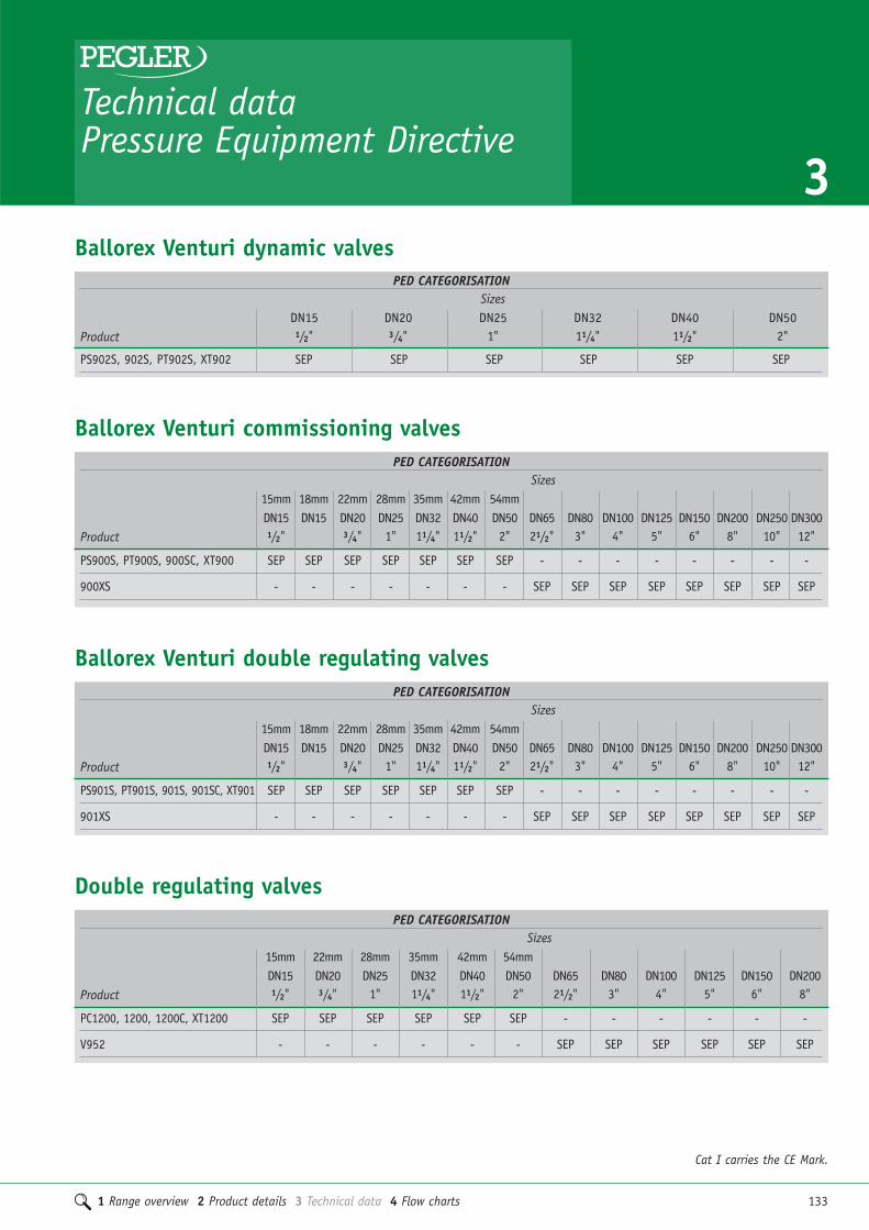
1 Range overview 2 Product details 3 Technical data 4 Flow charts 133
3Technical dataPressure Equipment Directive
Ballorex Venturi dynamic valvesPED CATEGORISATION
SizesDN15 DN20 DN25 DN32 DN40 DN50
Product 1/2" 3/4" 1" 11/4" 11/2" 2"
PS902S, 902S, PT902S, XT902 SEP SEP SEP SEP SEP SEP
PED CATEGORISATIONSizes
15mm 18mm 22mm 28mm 35mm 42mm 54mmDN15 DN15 DN20 DN25 DN32 DN40 DN50 DN65 DN80 DN100 DN125 DN150 DN200 DN250 DN300
Product 1/2" 3/4" 1" 11/4" 11/2" 2" 21/2" 3" 4" 5" 6" 8" 10" 12"
PS900S, PT900S, 900SC, XT900 SEP SEP SEP SEP SEP SEP SEP - - - - - - - -
900XS - - - - - - - SEP SEP SEP SEP SEP SEP SEP SEP
PED CATEGORISATIONSizes
15mm 18mm 22mm 28mm 35mm 42mm 54mmDN15 DN15 DN20 DN25 DN32 DN40 DN50 DN65 DN80 DN100 DN125 DN150 DN200 DN250 DN300
Product 1/2" 3/4" 1" 11/4" 11/2" 2" 21/2" 3" 4" 5" 6" 8" 10" 12"
PS901S, PT901S, 901S, 901SC, XT901 SEP SEP SEP SEP SEP SEP SEP - - - - - - - -
901XS - - - - - - - SEP SEP SEP SEP SEP SEP SEP SEP
Cat I carries the CE Mark.
Ballorex Venturi commissioning valves
Ballorex Venturi double regulating valves
PED CATEGORISATIONSizes
15mm 22mm 28mm 35mm 42mm 54mmDN15 DN20 DN25 DN32 DN40 DN50 DN65 DN80 DN100 DN125 DN150 DN200
Product 1/2" 3/4" 1" 11/4" 11/2" 2" 21/2" 3" 4" 5" 6" 8"
PC1200, 1200, 1200C, XT1200 SEP SEP SEP SEP SEP SEP - - - - - -
V952 - - - - - - SEP SEP SEP SEP SEP SEP
Double regulating valves

PED CATEGORISATIONSizes
DN15 DN20 DN25 DN32 DN40 DN50 DN65 DN80 DN100 DN125 DN150 DN200 DN250 DN300 DN350 DN400 DN500Product 1/2" 3/4" 1" 11/4" 11/2" 2" 21/2" 3" 4" 5" 6" 8" 10" 12" 14" 16" 20"
PB1000, PB1001, PB1002 Cat III Cat III Cat III Cat III Cat III Cat III - - - - - - - - - - -
PB1003 - - - - - - Cat III Cat III Cat III - - - - - - - -
PB1004 - - - - - - - - - Cat III Cat III Cat III Cat III Cat III Cat III Cat III Cat III
Ballomax ball valves
134 1 Range overview 2 Product details 3 Technical data 4 Flow charts
Technical dataPressure Equipment Directive
PED CATEGORISATIONSizes
15mm 18mm 22mm 28mm 35mm 42mm 54mmDN15 DN15 DN20 DN25 DN32 DN40 DN50 DN65 DN80 DN100 DN125 DN150 DN200 DN250 DN300
Product 1/2" 3/4" 1" 11/4" 11/2" 2" 21/2" 3" 4" 5" 6" 8" 10" 12"
PS1260, 1260, 1260C, PS1250,
PT1250, 1250, 1250C, SEP SEP SEP SEP SEP SEP SEP - - - - - - - -
XT1250, XT1260
900RM, V953 - - - - - - SEP SEP SEP SEP SEP SEP SEP SEP SEP
Commissioning valves and metering stations
PED CATEGORISATIONSizes
15mm 22mm 28mm 35mm 42mm 54mmDN8 DN10 DN15 DN20 DN25 DN32 DN40 DN50 DN65 DN80 DN100
Product 1/4" 3/8" 1/2" 3/4" 1" 11/4" 11/2" 2" 21/2" 3" 4"
PB700, PB700T, PB500 (yellow) SEP SEP SEP SEP SEP Cat I Cat I Cat I Cat I Cat I Cat I
PB500 (red), PB500T (red) SEP SEP SEP SEP SEP SEP SEP SEP SEP SEP SEP
PS500, PT500, XT500 - - SEP SEP SEP SEP SEP SEP - - -
PS500T, PT500T, PB500T SEP SEP SEP SEP SEP - - - - - -
PS550, PT550, PB550DR, PB550DR T, PB550DR LS, XT550, - - SEP SEP SEP SEP SEP SEP - - -PB500EL, PB550EL, XT550EL,PS550EL, PB350, PB350LS, PB300, PB350EL
PS550T, PT550T, PB350T, PB300T - - SEP SEP SEP - - - - - -
PB560, PB560EXT,- - SEP SEP - - - - - -
PB50HU, PB52HU
PB100 - - SEP SEP SEP SEP SEP SEP SEP SEP SEP
1111BV - - - - SEP SEP SEP SEP - - -
TX490L - - SEP SEP - - - - - - -
Quarter turn ball valves
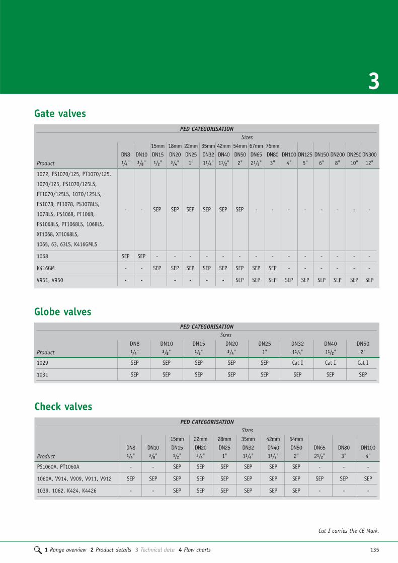
1 Range overview 2 Product details 3 Technical data 4 Flow charts 135
3
Cat I carries the CE Mark.
Gate valvesPED CATEGORISATION
Sizes15mm 18mm 22mm 35mm 42mm 54mm 67mm 76mm
DN8 DN10 DN15 DN20 DN25 DN32 DN40 DN50 DN65 DN80 DN100 DN125 DN150 DN200 DN250DN300Product 1/4" 3/8" 1/2" 3/4" 1" 11/4" 11/2" 2" 21/2" 3" 4" 5" 6" 8" 10" 12"
1072, PS1070/125, PT1070/125,
1070/125, PS1070/125LS,
PT1070/125LS, 1070/125LS,
PS1078, PT1078, PS1078LS, - - SEP SEP SEP SEP SEP SEP - - - - - - - -
1078LS, PS1068, PT1068,
PS1068LS, PT1068LS, 1068LS,
XT1068, XT1068LS,
1065, 63, 63LS, K416GMLS
1068 SEP SEP - - - - - - - - - - - - - -
K416GM - - SEP SEP SEP SEP SEP SEP SEP SEP - - - - - -
V951, V950 - - - - - - SEP SEP SEP SEP SEP SEP SEP SEP SEP
Globe valvesPED CATEGORISATION
SizesDN8 DN10 DN15 DN20 DN25 DN32 DN40 DN50
Product 1/4" 3/8" 1/2" 3/4" 1" 11/4" 11/2" 2"
1029 SEP SEP SEP SEP SEP Cat I Cat I Cat I
1031 SEP SEP SEP SEP SEP SEP SEP SEP
PED CATEGORISATIONSizes
15mm 22mm 28mm 35mm 42mm 54mmDN8 DN10 DN15 DN20 DN25 DN32 DN40 DN50 DN65 DN80 DN100
Product 1/4" 3/8" 1/2" 3/4" 1" 11/4" 11/2" 2" 21/2" 3" 4"
PS1060A, PT1060A - - SEP SEP SEP SEP SEP SEP - - -
1060A, V914, V909, V911, V912 SEP SEP SEP SEP SEP SEP SEP SEP SEP SEP SEP
1039, 1062, K424, K4426 - - SEP SEP SEP SEP SEP SEP - - -
Check valves

136 1 Range overview 2 Product details 3 Technical data 4 Flow charts
Technical dataPressure Equipment Directive
StrainersPED CATEGORISATION
Sizes15/18mm 22mm 28mm 35mm 42mm 54mm
DN15 DN20 DN25 DN32 DN40 DN50Product 1/2" 3/4" 1" 11/4" 11/2" 2"
V954, PS954, PS913, PT913, V913 SEP SEP SEP SEP SEP SEP
DraincocksPED CATEGORISATION
SizesDN15 DN20 DN25
Product 1/2" 3/4" 1"
1832, PB60HU, 833GM, 833GM LS SEP SEP SEP
Butterfly valvesPED CATEGORISATION
SizesDN65 DN80 DN100 DN125 DN150 DN200 DN250 DN300
Product 21/2" 3" 4" 5" 6" 8" 10" 12"
V907, V907G, V906, V906G,SEP SEP SEP SEP SEP SEP SEP SEP
V905, V905G
PED CATEGORISATIONSizes
DN15 DN20 DN25 DN32 DN40 DN50 DN65 DN80 DN100 DN125 DN150 DN200 DN250 DN300 DN350 DN400 DN500Product 1/2" 3/4" 1" 11/4" 11/2" 2" 21/2" 3" 4" 5" 6" 8" 10" 12" 14" 16" 20"
PB1005 Cat III Cat III Cat III Cat III Cat III Cat III - - - - - - - - - - -
PB1006 - - - - - - Cat III Cat III Cat III Cat III Cat III Cat III Cat III Cat III Cat III Cat III Cat III
Ballomax ball valves

1 Range overview 2 Product details 3 Technical data 4 Flow charts 137
3Technical dataFlange tables
PN16 BS EN 1092-1:2007 DN65-DN300 – 900XSS, 900XSL, 901XS, V905, V905G, V906, V906G
Flange Pitch Circle No. Bolt Hole Raised Face Raised Face ThicknessDiameter Diameter of Diameter Diameter Diameter Height of Flange
(mm) (mm) Bolts (mm) (mm) (mm) (mm) (mm)
DN65 185 145 4 (2) M16 19 - - 20
DN80 200 160 8 M16 19 - - 22
DN100 220 180 8 M16 19 - - 24
DN125 250 210 8 M16 19 - - 26
DN150 285 240 8 M20 23 - - 26
DN200 340 295 12 M20 23 - - 30
DN250 405 (2) 355 12 M24 28 - - 32
DN300 460 (2) 410 12 M24 28 - - 32
PN6 BS EN 1092-1:1997 DN65-DN300 – V907, V907G, V951
Flange Pitch Circle No. Bolt Hole Raised Face Raised Face ThicknessDiameter Diameter of Diameter Diameter Diameter Height of Flange
(mm) (mm) Bolts (mm) (mm) (mm) (mm) (mm)
DN65 160 130 4 M12 14 - - 16
DN80 190 150 4 M16 19 - - 18
DN100 210 170 4 M16 19 - - 18
DN125 240 200 8 M16 19 - - 20
DN150 265 225 8 M16 19 - - 20
DN200 320 280 8 M16 19 - - 22
DN250 375 335 12 M16 19 - - 24
DN300 440 395 12 M20 23 - - 24
PN16 BS EN 1092-1:1997 DN65-DN300 – V914, V912, V950, V952
Flange Pitch Circle No. Bolt Hole Raised Face Raised Face ThicknessDiameter Diameter of Diameter Diameter Diameter Height of Flange
(mm) (mm) Bolts (mm) (mm) (mm) (mm) (mm)
DN65 185 145 4 (2) M16 19 - - 20
DN80 200 160 8 M16 19 - - 22
DN100 220 180 8 M16 19 - - 24
DN125 250 210 8 M16 19 - - 26
DN150 285 240 8 M20 23 - - 26
DN200 340 295 12 M20 23 - - 30
DN250 405 (2) 355 12 M24 28 - - 32
DN300 460 (2) 410 12 M24 28 - - 32

138 1 Range overview 2 Product details 3 Technical data 4 Flow charts
PN16 DIN2633 DN65-DN500 – PB1006
Flange Pitch Circle No. Bolt Hole Raised Face Raised Face ThicknessDiameter Diameter of Diameter Diameter Diameter Height of Flange
(mm) (mm) Bolts (mm) (mm) (mm) (mm) (mm)
DN65 185 145 4 (2) M16 18 122 3 14
DN80 200 160 8 M16 18 138 2 20
DN100 220 180 8 M16 18 158 2 20
DN125 250 210 8 M16 18 188 2 22
DN150 285 240 8 M20 22 212 2 22
DN200 340 295 12 M20 22 268 2 24
DN250 405 (2) 355 12 M24 26 320 2 26
DN300 460 (2) 410 12 M24 26 370 2 28
DN350 520 470 16 M24 26 438 2 30
DN400 580 525 16 M27 30 490 2 32
DN500 715 650 20 M30 33 610 2 44 (2)
PN40 DIN2633 DN15-DN50 – PB1005
Flange Pitch Circle No. Bolt Hole Raised Face Raised Face ThicknessDiameter Diameter of Diameter Diameter Diameter Height of Flange
(mm) (mm) Bolts (mm) (mm) (mm) (mm) (mm)
DN15 95 65 4 M12 14 45 2 16
DN20 105 75 4 M12 14 58 2 18
DN25 115 85 4 M12 14 68 2 18
DN32 140 100 4 M16 18 78 2 18
DN40 150 110 4 M16 18 88 2 18
DN50 165 125 4 M16 18 102 2 20
Technical dataFlange tables

1 Range overview 2 Product details 3 Technical data 4 Flow charts 139
3Commercial valve solutionsConnection instructions
1. Select the correct size of tube and fittingfor the job. Ensure that both are clean, ingood condition and free from damage andimperfections.
2. Cut the tube square using a rotary tubecutter whenever possible. If a hacksaw isused to cut the tube, a fine toothed bladeshould be used, care must be taken to ensurethat the tube is cut square and properly de-burred.
When using plastic coated carbon steel tube, the coating must be removed to theexact socket depth of the fitting and thetube deburred.
3. The tube end should then be wiped cleanof all swarf and debris, to avoid damage tothe 'O' ring upon tube insertion.
4. To make a perfect joint, the tube must befully inserted into the fitting until it meetsthe tube stop.
5. Ensure that the 'O' ring is seated correctlywithin the fitting socket.
Jointing1. Assemble the joint, ensuring that the tubeis inserted into the connection until itmeets the tube stop. The mark on the tubemade earlier should be used as a guide toensure this is the case. For plastic coatedcarbon steel tube, the mouth of the fittingshould be in contact with the plasticcoating. Only when the tube reaches thetube stop should the pressing operation be undertaken.
2. With the correctly sized jaws inserted intothe press tool, place them over the bead atthe mouth of the fitting. A 90º angle betweentube and jaws must be maintained to ensurea sound joint is made.
3. Depressing the trigger or button willcommence the compression cycle of the tool,which is complete when the jaws fully enclosethe mouth of the fitting. The jaws shouldthen be released from around the fitting.Please refer to the tool manufacturersinstructions for further detailed information.
Spacing
In order to make a joint correctly sufficientclearance around each fitting must be left to allow press-fit jaws to be attachedwithout hindrance.
For full installation details refer to XPress data book.
Press-fit connections
FITTING SOCKET DEPTHSSize Copper/Stainless/Carbon
15mm 20mm18mm 20mm22mm 21mm28mm 23mm35mm 26mm42mm 30mm54mm 35mm

140 1 Range overview 2 Product details 3 Technical data 4 Flow charts
Commercial valve solutionsConnection instructions
Ensure that threads are prepared correctly toprovide a good and long lasting service.
Pipe compound should be applied to pipeends only and not directly into the valve.
Valves should not be over tightened with a wrench.
Ensure the pipe is threaded to the correcttype and length. If the pipe is threaded tooshort a leak may occur. If the pipe isthreaded too long then damage may bemade to the valve.
Ensure that good quality tools are used toprovide an accurate joint and thereforeavoiding the risk of leaking.
Thread tape may be used and applied to theexternal of the pipe thread after the threadshave been cleaned.
Joining the valve and pipe.Fix the threaded pipe into a vice and thenturn the valve on to the pipe.
A close fitting spanner should be applied to the valve hexagon/octagon flats beingfixed. By tightening the valve onto the pipe in this way, the valve avoids beingdistorted with the consequential damage to internal parts.
Threaded connections
For joints 15 to 54mm1. Always cut the tube square, using a rotarytube cutter whenever possible.
If you are using PEX or PB pipe cut the pipeusing pipe shears. When using plasticcoated carbon steel tube remove thecoating using the S115 stripping tool.
Deburr the tube end, both internally andexternally to create a 1mm chamfer on theoutside of the tube.
Check the tube ends are free from damageand clean, wiping away any swarf to avoiddamaging the ‘O’ ring on tube insertion.Tube end must also be free from stickers,tape and adhesive residues.
Where using PEX or PB you must use alwaysinsert a support liner ensuring it is thecorrect liner as specified by the pipemanufacturer. If the pipe has been used onprevious installations you will need to cut itback to behind the teeth or score marks.
Mark the socket depth with a marker.
For chrome plated copper tube you mustscribe the tube using the correct TectiteScribing tool.
Select the correct type and size of fittingfor pipework.
Push-fit solutionsThe fitting should be kept in its bag untilpoint of use to protect the ‘O’ ring.
2. Inspect the fitting ensuring that the grabrings/‘O’ rings have not been contaminatedwith grit or debits. Insert the pipe into themouth of the fitting to rest against the grab ring.
3. Push the tube firmly with a slight twistingaction until it reaches the tube stop.
4. Ensure the depth insertion markcorresponds with the mouth of the fittingand then pull firmly on the tube to ensurethe fitting is secure.
35mm to 54mm sizesThe first thing to consider when it comes to installation of 35mm to 54mm fittings iswhether you plan to demount any fittings inthe system on a regular basis. If you do,then we recommend you replace the standardend cap with the appropriately sized TDXdemounting end cap.
To ensure the fittings stay clean and the 'O'ring is protected from damage, never removethe fitting from its packaging untilimmediately prior to installation.
5. Insert the tube through the end cap to rest against the grab ring.
6. Now push the tube firmly with a slight twisting action until it reaches the tube stop.
7. Ensure the depth insertion markcorresponds with the mouth of the fitting,then pull firmly on the tube to ensure thatthe fitting is secure.
NOTE: We recommend all systems arethoroughly pressure tested to 1.5 timesworking pressure before the hand-over to the customer.
For full installation details refer to Tectite data book.
Push-fit connections
FITTING SOCKET DEPTHS FOR TECTITESize Sprint & Copper/Stainless/
Advance* Carbon
10mm 15mm 23mm15mm 18mm 23mm18mm - 23mm22mm 19mm 27mm28mm 20mm 31mm35mm 31mm* 57mm42mm 32mm* 62mm54mm 37mm* 68mm

1 Range overview 2 Product details 3 Technical data 4 Flow charts 141
3
1. Select the correct size of tube for the job.Ensure that it is clean, in good condition andfree from damage and imperfections. If thetube is oval or damaged, use a re-roundingtool. Copper tube should be of half-hard(R250) or hard (R290) temper. Annealed soft temper tube (R220) can be used.
2. Cut the tube square using a rotary tubecutter wherever possible. If a hacksaw is usedto cut the tube, a fine toothed blade shouldbe used.
3. Remove any burr from the inside andoutside of the tube ends using a fine toothedfile or a S120 deburring tool from the XPressaccessories range.
Connecting copper tubeThere are two methods of making acompression joint.
1. Insert the tube firmly into the compressionfitting, ensuring that the compression ring
seats centrally and that the tube makes firmcontact with the tube stop in the body ofthe fitting.
2. Remove the compression nut andcompression ring, then put the nut and thenthe ring on the tube. Insert the tube end upto the fitting's tube stop. Slide the ring andthe nut down to the fitting body.
3. Tighten the nut using your fingers until tight.
4. Tighten the nut further using high qualityopen ended or adjustable spanners. Spannerflats are incorporated into the design of thefitting bodies. The second spanner must beused to prevent the fitting rotating as the nutis tightened. For normal joint making, tightenthe nut 1 turn (360°) for fittings in sizesfrom 6mm to 12mm, or 3⁄4 turn (270°) forfittings in sizes from 15mm to 54mm. A fewdrops of light oil on the threads will assist,especially on sizes 35mm and above. Whenjointing stainless steel or R220 copper tubesome variation may be needed – the nut maybe tightened further if necessary. Take carenot to over tighten the compression nut, asthis will not result in a stronger joint andcould lead to problems in service.
Connecting half-hard thick walled R250 copper tubeThis copper tube is significantly thicker thanother varieties and special care needs to betaken during installation.
1. Ensure pipework is supported during andafter installation, as thick-walled coppertube is less tolerant of stress on the joints.The pipework should be clipped as close aspossible to the fittings, particularly wherelong runs are involved.
2. Use spanners of the correct size andlength. More torque is required to tightenfittings with thick walled copper tube, andcare should be taken to ensure neighbouringjoints are not disturbed.
3. Apply a light oil to the threads andchamfers where possible. This will reduceassembly torque and minimise the risk ofdamage. This is essential on sizes above 28mm.
4. If a sealant is required, use a suitable PTFEbased compound, eg. Loctite 577 or PTFE tape.
Connecting imperial copper tubePegler valves with compression connectionscan be used in maintenance applications toconnect copper tube to former imperial sizes,such as BS 3931.
Connecting carbon steel and stainless steel tubeStainless steel tube to BS EN 10312 (formerlyBS 4127), DVGW GW541; and carbon steeltube to DIN 2394/ NEN 1982, can be jointedin sizes up to and including 28mm usingPegler compression fittings. Carbon steeltubes are for use on non potable closedcircuit systems only. To achieve sound joints,the following precautions should be taken:
1. Ensure no flats or score marks are visibleon the outside surface of the tube. The weldbead should not be visible.
2. A suitable jointing compound should be applied to the sealing faces prior totightening of the compression nuts. Sealantswith PTFE fillers are preferred, with PTFEtape as an alternative.
Compressionconnections

142 1 Range overview 2 Product details 3 Technical data 4 Flow charts
Commercial valve solutionsConnection instructions
Flange material specification:
� Pressure and temperature must not exceedits rating.
� Gasket selection must be in line with therating of the flange.
� The fluid being handled will affect thegasket selection.
� All bolts must be compatible with theflange being used.
Pipe and its mating flanges should becleaned and made ready for assembly.
A clean and appropriate gasket should beselected for the flange type being used. Flatface and raised faces should not be mixed.
Piping should being properly supported with use of correctly sized hanging orsecuring brackets.
Flange components have their own designlimitations and correct selection andcompatibility is vital.
All pipes need to be aligned correctly to ensure that the valve integrity ismaintained, avoiding twisting and distortionof the valve’s structure and valve damage.
As the valve is assembled ensure that the bolts are placed and secured with nuts at hand tightness employing thecrossover method of tightening to secure a sound joint.
Butterfly valves provide positive shut off inboth flow directions. The disc profile isdesigned to give sealing properties atminimum torque. Raised seat profile provides positive flange seal.
Flange connections
Welded joints should be made by qualifiedinstallers having carried out the requisiterisk assessments and health and safety considerations.
Welded connections

1 Range overview 2 Product details 3 Technical data 4 Flow charts 143
Calculation of flow rate: FODRV DN 15L - Low flow
Sign
al Kv
s = 0
,359
0,007 0,008 0,01 0,02 0,03 0,04 0,05 0,06 0,07 0,08 0,10,0252 0,0288 0,036 0,072 0,108 0,144 0,180 0,216 0,252 0,288 0,36
1009080
70
60
50
40
30
20
1098
7
6
5
4
3
2
1
Bold area indicates signal between 10 – 60 kPa, for flow range according to BS 7350.
SignalkPammH2
2O x 10
l/sm3/h
Flow rate
FODRV DN 15S - Standard flow
1009080
70
60
50
40
30
20
1098
7
6
5
4
3
2
1
Sign
al Kv
s = 0
,746
0,01 0,02 0,03 0,04 0,05 0,06 0,07 0,08 0,1 0,20,036 0,072 0,108 0,144 0,180 0,216 0,252 0,288 0,36 0,72
Bold area indicates signal between 10 – 60 kPa, for flow range according to BS 7350.
l/sm3/h
Flow rate
SignalkPammH2
2O x 10
FODRV DN 15H - High flow
1009080
70
60
50
40
30
20
1098
7
6
5
4
3
2
1
Sign
al Kv
s = 1
,56
0,03 0,04 0,05 0,06 0,07 0,08 0,1 0,2 0,3 0,4 0,5 0,6 0,70,108 0,144 0,180 0,216 0,252 0,288 0,36 0,72 1,08 1,44 1,80 2,16 2,52
Bold area indicates signal between 10 – 60 kPa, for flow range according to BS 7350.
l/sm3/h
Flow rate
SignalkPammH2
2O x 10
Kvs x ΔP36 Q =
WhereQ = Flow rate (l/s)ΔP = Signal (kPa)Kvs = Signal coefficient
4Commercial valve solutionsBallorex Commissioning productsFlow charts

144 1 Range overview 2 Product details 3 Technical data 4 Flow charts
Commercial valve solutionsBallorex Commissioning productsFlow charts
FODRV DN 20L - Low flowSignalkPammH2
2O x 10
l/sm3/h
Flow rate
1009080
70
60
50
40
30
20
1098
7
6
5
4
3
2
1
Sign
al Kv
s = 0
,746
0,01 0,02 0,03 0,04 0,05 0,06 0,07 0,08 0,1 0,20,036 0,072 0,108 0,144 0,180 0,216 0,252 0,288 0,36 0,72
Bold area indicates signal between 10 – 60 kPa, for flow range according to BS 7350.
FODRV DN 20S - Standard flow
1009080
70
60
50
40
30
20
1098
7
6
5
4
3
2
1
Sign
al Kv
s = 1
,56
0,03 0,04 0,05 0,06 0,07 0,08 0,1 0,2 0,3 0,4 0,5 0,6 0,70,108 0,144 0,180 0,216 0,252 0,288 0,36 0,72 1,08 1,44 1,80 2,16 2,52
Bold area indicates signal between 10 – 60 kPa, for flow range according to BS 7350.
SignalkPammH2
2O x 10
l/sm3/h
Flow rate
FODRV DN 20H - High flow
1009080
70
60
50
40
30
20
1098
7
6
5
4
3
2
1
Sign
al Kv
s = 2
,95
0,05 0,06 0,07 0,08 0,1 0,2 0,3 0,4 0,5 0,6 0,7 0,8 1,00,180 0,216 0,252 0,288 0,36 0,72 1,08 1,44 1,80 2,16 2,52 2,88 3,6
Bold area indicates signal between 10 – 60 kPa, for flow range according to BS 7350.
SignalkPammH2
2O x 10
l/sm3/h
Flow rate
FODRV DN 25S - Standard flow
1009080
70
60
50
40
30
20
1098
7
6
5
4
3
2
1
Sign
al Kv
s = 2
,95
0,06 0,07 0,08 0,1 0,2 0,3 0,4 0,5 0,6 0,7 0,8 1,00,216 0,252 0,288 0,36 0,72 1,08 1,44 1,80 2,16 2,52 2,88 3,6
Bold area indicates signal between 10 – 60 kPa, for flow range according to BS 7350.
l/sm3/h
Flow rate
SignalkPammH2
2O x 10

1 Range overview 2 Product details 3 Technical data 4 Flow charts 145
4FODRV DN 25H - High flow FODRV DN 32H - High flow
1009080
70
60
50
40
30
20
1098
7
6
5
4
3
2
1
Sign
al Kv
s = 6
,01
0,1 0,2 0,3 0,4 0,5 0,6 0,7 0,8 1,0 0,20,36 0,72 1,08 1,44 1,80 2,16 2,52 2,88 3,6 7,2
Bold area indicates signal between 10 – 60 kPa, for flow range according to BS 7350.
l/sm3/h
Flow rate
SignalkPammH2
2O x 10
1009080
70
60
50
40
30
20
1098
7
6
5
4
3
2
1
Sign
al Kv
s = 6
,01
0,1 0,2 0,3 0,4 0,5 0,6 0,7 0,8 1,0 2,00,36 0,72 1,08 1,44 1,80 2,16 2,52 2,88 3,6 7,2
Bold area indicates signal between 10 – 60 kPa, for flow range according to BS 7350.
SignalkPammH2
2O x 10
l/sm3/h
Flow rate
FODRV DN 40H - High flow
Sign
al Kv
s = 9
,2
0,2 0,3 0,4 0,5 0,6 0,7 0,8 1,0 2,0 3,0 4,00,72 1,08 1,44 1,80 2,16 2,52 2,88 3,6 7,2 10,8 14,4
1009080
70
60
50
40
30
20
1098
7
6
5
4
3
2
1
Bold area indicates signal between 10 – 60 kPa, for flow range according to BS 7350.
SignalkPammH2
2O x 10
l/sm3/h
Flow rate
FODRV DN 50H - High flow
Sign
al Kv
s = 1
7,1
0,4 0,5 0,6 0,7 0,8 1,0 2,0 3,0 4,0 5,0 6,0 7,0 8,0 101,44 1,80 2,16 2,52 2,88 3,6 7,2 10,8 14,4 18,0 21,6 25,2 28,8 36
1009080
70
60
50
40
30
20
1098
7
6
5
4
3
2
1
Bold area indicates signal between 10 – 60 kPa, for flow range according to BS 7350.
SignalkPammH2
2O x 10
l/sm3/h
Flow rate

146 1 Range overview 2 Product details 3 Technical data 4 Flow charts
Commercial valve solutionsBallorex Commissioning productsFlow charts
FODRV DN 65 - Standard and ExtendedSi
gnal
Kvs =
37,
4
0,6 0,7 0,8 1,0 2,0 3,0 4,0 5,0 6,0 7,0 8,0 102,16 2,52 2,88 3,6 7,2 10,8 14,4 18,0 21,6 25,2 28,8 36
1009080
70
60
50
40
30
20
1098
7
6
5
4
3
2
1
Bold area indicates signal between 10 – 60 kPa, for flow range according to BS 7350.
l/sm3/h
Flow rate
SignalkPammH2
2O x 10
FODRV DN 80 - Standard and Extended
Sign
al Kv
s = 7
2,9
1,0 2,0 3,0 4,0 5,0 6,0 7,0 8,0 10 203,6 7,2 10,8 14,4 18,0 21,6 25,2 28,8 36 72
1009080
70
60
50
40
30
20
1098
7
6
5
4
3
2
1
Bold area indicates signal between 10 – 60 kPa, for flow range according to BS 7350.
l/sm3/h
Flow rate
SignalkPammH2
2O x 10
FODRV DN 100 - Standard and Extended
Sign
al K
vs =
129
2,0 3,0 4,0 5,0 6,0 7,0 8,0 10 20 30 407,2 10,8 14,4 18,0 21,6 25,2 28,8 36 72 108 144
1009080
70
60
50
40
30
20
1098
7
6
5
4
3
2
1
Bold area indicates signal between 10 – 60 kPa, for flow range according to BS 7350.
l/sm3/h
Flow rate
SignalkPammH2
2O x 10
FODRV DN 125 - Standard and Extended
Sign
al Kv
s = 1
90
3,0 4,0 5,0 6,0 7,0 8,0 10 20 30 40 50 60 7010,8 14,4 18,0 21,6 25,2 28,8 36 72 108 144 180 216 252
1009080
70
60
50
40
30
20
1098
7
6
5
4
3
2
1
Bold area indicates signal between 10 – 60 kPa, for flow range according to BS 7350.
SignalkPammH2
2O x 10
l/sm3/h
Flow rate

1 Range overview 2 Product details 3 Technical data 4 Flow charts 147
4FODRV DN 150 - Standard and Extended FODRV DN 200 - Standard
Sign
al Kv
s = 5
86
10 20 30 40 50 60 70 80 100 20036 72 108 144 180 216 252 288 360 720
1009080
70
60
50
40
30
20
1098
7
6
5
4
3
2
1
Bold area indicates signal between 10 – 60 kPa, for flow range according to BS 7350.
l/sm3/h
Flow rate
SignalkPammH2
2O x 10
Sign
al Kv
s = 3
48
7,0 8,0 10 20 30 40 50 60 70 80 10025,2 28,8 36 72 108 144 180 216 252 288 360
1009080
70
60
50
40
30
20
1098
7
6
5
4
3
2
1
Bold area indicates signal between 10 – 60 kPa, for flow range according to BS 7350.
l/sm3/h
Flow rate
SignalkPammH2
2O x 10
FODRV DN 250 - Standard
Sign
al Kv
s = 8
61
20 30 40 50 60 70 80 100 200 300 40072 108 144 180 216 252 288 360 720 1080 1440
1009080
70
60
50
40
30
20
1098
7
6
5
4
3
2
1
Bold area indicates signal between 10 – 60 kPa, for flow range according to BS 7350.
l/sm3/h
Flow rate
SignalkPammH2
2O x 10
FODRV DN 300 - Standard
Sign
al Kv
s = 1
513
30 40 50 60 70 80 100 200 300 400 500 600 700108 144 180 216 252 288 360 720 1080 1440 1800 2160 2520
1009080
70
60
50
40
30
20
1098
7
6
5
4
3
2
1
Bold area indicates signal between 10 – 60 kPa, for flow range according to BS 7350.
l/sm3/h
Flow rate
SignalkPammH2
2O x 10

148 1 Range overview 2 Product details 3 Technical data 4 Flow charts
Commercial valve solutionsBallorex Commissioning productsFlow charts
DRV DN 15L - Low flow
Posit
ion
0.0
Posit
ion
1.0
Posit
ion
2.0
Posit
ion
3.0
Posit
ion
4.0
Posit
ion
6.0
Posit
ion
5.0
Posit
ion
7.0
Posit
ion
8.0
Posit
ion
9.0
Posit
ion
9.9
Position
Position 0.0 1.0 2.0 3.0 4.0 5.0 6.0 7.0 8.0 9.0 9.9
Kv 0,083 0,095 0,159 0,248 0,365 0,519 0,712 0,932 1,16 1,40 1,62
0,008 0,01 0,02 0,03 0,04 0,05 0,06 0,07 0,08 0,1 0,20,028 0,036 0,072 0,108 0,144 0,180 0,216 0,252 0,288 0,36 0,72
1009080
70
60
50
40
30
20
1098
7
6
5
4
3
2
1l/s
m3/h
Flow rate
SignalkPammH2
2O x 10
DRV DN 15S - Standard flow
1009080
70
60
50
40
30
20
1098
7
6
5
4
3
2
1
Posit
ion
0.0
Posit
ion
1.0
Posit
ion
2.0
Posit
ion
3.0
Posit
ion
4.0
Posit
ion
6.0
Posit
ion
5.0
Posit
ion
7.0
Posit
ion
8.0
Posit
ion
9.0
Posit
ion
9.9
Position
Position 0.0 1.0 2.0 3.0 4.0 5.0 6.0 7.0 8.0 9.0 9.9
Kv 0,261 0,267 0,334 0,449 0,601 0,785 1,00 1,26 1,55 1,86 2,11
0,02 0,03 0,04 0,05 0,06 0,07 0,08 0,1 0,2 0,3 0,4 0,50,072 0,108 0,144 0,180 0,216 0,252 0,288 0,36 0,72 1,08 1,44 1,80
l/sm3/h
Flow rate
SignalkPammH2
2O x 10
DRV DN 20L - Low flow
Position 0.0 1.0 2.0 3.0 4.0 5.0 6.0 7.0 8.0 9.0 9.9
Kv 0,094 0,250 0,541 0,870 1,22 1,60 2,03 2,53 3,07 3,67 4,26
Posit
ion
0.0
Posit
ion
1.0
Posit
ion
2.0
Posit
ion
3.0
Posit
ion
4.0
Posit
ion
6.0
Posit
ion
5.0
Posit
ion
7.0
Posit
ion
8.0
Posit
ion
9.0
Posit
ion
9.9
Position
0,02 0,03 0,04 0,05 0,06 0,07 0,08 0,1 0,2 0,3 0,4 0,50,072 0,108 0,144 0,180 0,216 0,252 0,288 0,36 0,72 1,08 1,44 1,80
1009080
70
60
50
40
30
20
1098
7
6
5
4
3
2
1l/s
m3/h
Flow rate
SignalkPammH2
2O x 10
DRV DN 20S - Standard flow
1009080
70
60
50
40
30
20
1098
7
6
5
4
3
2
10,03 0,04 0,05 0,06 0,07 0,08 0,1 0,2 0,3 0,4 0,5 0,6 0,70,108 0,144 0,180 0,216 0,252 0,288 0,36 0,72 1,08 1,44 1,80 2,16 2,52
Position 0.0 1.0 2.0 3.0 4.0 5.0 6.0 7.0 8.0 9.0 9.9
Kv 0,325 0,494 0,778 1,12 1,50 1,93 2,41 2,93 3,48 4,10 4,81
Position 0.0 1.0 2.0 3.0 4.0 5.0 6.0 7.0 8.0 9.0 9.9
Kv 0,325 0,494 0,778 1,12 1,50 1,93 2,41 2,93 3,48 4,10 4,81
Position 0.0 1.0 2.0 3.0 4.0 5.0 6.0 7.0 8.0 9.0 9.9
Kv 0,325 0,494 0,778 1,12 1,50 1,93 2,41 2,93 3,48 4,10 4,81
Position 0.0 1.0 2.0 3.0 4.0 5.0 6.0 7.0 8.0 9.0 9.9
Kv 0,325 0,494 0,778 1,12 1,50 1,93 2,41 2,93 3,48 4,10 4,81
Posit
ion
0.0
Posit
ion
1.0
Posit
ion
2.0
Posit
ion
3.0
Posit
ion
4.0
Posit
ion
6.0
Posit
ion
5.0
Posit
ion
7.0
Posit
ion
8.0
Posit
ion
9.0
Posit
ion
9.9
Position
l/sm3/h
Flow rate
SignalkPammH2
2O x 10

1 Range overview 2 Product details 3 Technical data 4 Flow charts 149
4DRV DN 25S - Standard flow DRV DN 32S - Standard flow
1009080
70
60
50
40
30
20
1098
7
6
5
4
3
2
1
Position 0.0 1.0 2.0 3.0 4.0 5.0 6.0 7.0 8.0 9.0 9.9
Kv 1,95 2,32 3,05 3,97 5,00 6,12 7,36 8,70 10,1 11,7 13,3
Posit
ion
0.0
Posit
ion
1.0
Posit
ion
2.0
Posit
ion
3.0
Posit
ion
4.0
Posit
ion
6.0
Posit
ion
5.0
Posit
ion
7.0
Posit
ion
8.0
Posit
ion
9.0
Posit
ion
9.9
Position
0,1 0,2 0,3 0,4 0,5 0,6 0,7 0,8 1,0 2,00,36 0,72 1,08 1,44 1,80 2,16 2,52 2,88 3,6 7,2
SignalkPammH2
2O x 10
l/sm3/h
Flow rate
1009080
70
60
50
40
30
20
1098
7
6
5
4
3
2
1
Position
Position 0.0 1.0 2.0 3.0 4.0 5.0 6.0 7.0 8.0 9.0 9.9
Kv 0,921 1,26 1,86 2,58 3,38 4,24 5,21 6,29 7,49 8,78 9,94
Posit
ion
0.0
Posit
ion
1.0
Posit
ion
2.0
Posit
ion
3.0
Posit
ion
4.0
Posit
ion
6.0
Posit
ion
5.0
Posit
ion
7.0
Posit
ion
8.0
Posit
ion
9.0
Posit
ion
9.9
0,08 0,1 0,2 0,3 0,4 0,5 0,6 0,7 0,8 1,0 2,00,288 0,36 0,72 1,08 1,44 1,80 2,16 2,52 2,88 3,6 7,2
l/sm3/h
Flow rate
SignalkPammH2
2O x 10
DRV DN 40S - Standard flow
1009080
70
60
50
40
30
20
1098
7
6
5
4
3
2
1
Position
Position 0.0 1.0 2.0 3.0 4.0 5.0 6.0 7.0 8.0 9.0 9.9
Kv 2,60 3,48 4,86 6,50 8,31 10,3 12,4 14,6 17,1 20,0 23,3
Posit
ion
0.0
Posit
ion
1.0
Posit
ion
2.0
Posit
ion
3.0
Posit
ion
4.0
Posit
ion
6.0
Posit
ion
5.0
Posit
ion
7.0
Posit
ion
8.0
Posit
ion
9.0
Posit
ion
9.9
0,1 0,2 0,3 0,4 0,5 0,6 0,7 0,8 1,0 2,0 3,00,36 0,72 1,08 1,44 1,80 2,16 2,52 2,88 3,6 7,2 10,8
SignalkPammH2
2O x 10
l/sm3/h
Flow rate
DRV DN 50S - Standard flow
1009080
70
60
50
40
30
20
1098
7
6
5
4
3
2
1
Position
0,3 0,4 0,5 0,6 0,7 0,8 1,0 2,0 3,0 4,0 5,0 6,0 7,0 8,01,08 1,44 1,80 2,16 2,52 2,88 3,6 7,2 10,8 14,4 18,0 21,6 25,2 28,8
Position 0.0 1.0 2.0 3.0 4.0 5.0 6.0 7.0 8.0 9.0 9.9
Kv 5,37 6,95 9,25 11,6 14,0 16,8 20,0 23,4 26,9 30,7 35,3
Posit
ion
0.0
Posit
ion
1.0
Posit
ion
2.0
Posit
ion
3.0
Posit
ion
4.0
Posit
ion
6.0
Posit
ion
5.0
Posit
ion
7.0
Posit
ion
8.0
Posit
ion
9.0
Posit
ion
9.9
SignalkPammH2
2O x 10
l/sm3/h
Flow rate

150 1 Range overview 2 Product details 3 Technical data 4 Flow charts
Commercial valve solutionsBallorex Commissioning productsFlow charts
DRV DN 65
1009080
70
60
50
40
30
20
1098
7
6
5
4
3
2
1
Position 2 3 4 5 6
Kv 18,34 45,9 92,5 136 148
Posit
ion
2
Posit
ion
3
Posit
ion
4
Posit
ion
5Po
sitio
n 6
S = ClosedO = Open
Position
1,0 2,0 3,0 4,0 5,0 6,0 7,0 8,0 10 20 303,6 7,2 10,8 14,4 18,0 21,6 25,2 28,8 36 72 108
SignalkPammH2
2O x 10
l/sm3/h
Flow rate
DRV DN 80
1009080
70
60
50
40
30
20
1098
7
6
5
4
3
2
1
Position 2 3 4 5 6
Kv 28,3 62,5 128 222 237
S = ClosedO = Open
Position
Posit
ion
2
Posit
ion
3
Posit
ion
4
Posit
ion
5Po
sitio
n 6
2,0 3,0 4,0 5,0 6,0 7,0 8,0 10 20 30 40 507,2 10,8 14,4 18,0 21,6 25,2 28,8 36 72 108 144 180
l/sm3/h
Flow rate
SignalkPammH2
2O x 10
DRV DN 100
1009080
70
60
50
40
30
20
1098
7
6
5
4
3
2
1
Position 2 3 4 5 6
Kv 14,1 58,3 139 315 603
S = ClosedO = Open
Position
Posit
ion
2
Posit
ion
3
Posit
ion
4
Posit
ion
5
Posit
ion
6
2,0 3,0 4,0 5,0 6,0 7,0 8,0 10 20 30 40 50 607,2 10,8 14,4 18,0 21,6 25,2 28,8 36 72 108 144 180 216
l/sm3/h
Flow rate
SignalkPammH2
2O x 10
DRV DN 125
1009080
70
60
50
40
30
20
1098
7
6
5
4
3
2
13,0 4,0 5,0 6,0 7,0 8,0 10 20 30 40 50 60 70 80
10,8 14,4 18,0 21,6 25,2 28,8 36 72 108 144 180 216 252 288
Position 2 3 4 5 6
Kv 30,5 121 275 610 888
S = ClosedO = Open
Position
Posit
ion
2
Posit
ion
3
Posit
ion
4
Posit
ion
5Po
sitio
n 6
SignalkPammH2
2O x 10
l/sm3/h
Flow rate

1 Range overview 2 Product details 3 Technical data 4 Flow charts 151
4DRV DN 150
1009080
70
60
50
40
30
20
1098
7
6
5
4
3
2
1
Position 2 3 4 5 6
Kv 71,9 201 396 1288 2341
S = ClosedO = Open
Position
Posit
ion
2
Posit
ion
3
Posit
ion
4
Posit
ion
5
Posit
ion
6
8,0 10 20 30 40 50 60 70 80 100 20028,8 36 72 108 144 180 216 252 288 360 720
SignalkPammH2
2O x 10
l/sm3/h
Flow rate25,27,0
DRV DN 200
1009080
70
60
50
40
30
20
1098
7
6
5
4
3
2
1
Posit
ion
2
Posit
ion
3
Posit
ion
4
Posit
ion
5
Posit
ion
6
8,0 10 20 30 40 50 60 70 80 100 20028,8 36 72 108 144 180 216 252 288 360 720
S = ClosedO = Open
Position
l/sm3/h
Flow ratePosition 2 3 4 5 6
Kv 127 353 726 1806 2845
SignalkPammH2
2O x 10
DRV DN 250
100
90
80
70
60
50
40
30
20
10
9
8
7
6
5
4
3
2
1
S = ClosedO = Open
Position
Posit
ion 2
Posit
ion 3
Posit
ion 4
Posit
ion 5
Posit
ion 6
20 30 40 50 60 70 80 100 200 300 400 500 60072 108 144 180 216 252 288 360 720 1080 1440 1800 2160
l/sm3/h
Flow rate
SignalkPammH2
2O x 10
Position 2 3 4 5 6
Kv 234 642 1513 3297 4549
DRV DN 300
1009080
70
60
50
40
30
20
1098
7
6
5
4
3
2
1
S = ClosedO = Open
Position
Posit
ion
2
Posit
ion
3
Posit
ion
4
Posit
ion
5
Posit
ion
6
40 50 60 70 80 100 200 300 400 500 600 700 800 1000144 180 216 252 288 360 720 1080 1440 1800 2160 2520 2880 3600
Position 2 3 4 5 6
Kv 819 1422 2537 5331 7761
l/sm3/h
Flow rate
SignalkPammH2
2O x 10

152 1 Range overview 2 Product details 3 Technical data 4 Flow charts
Commercial valve solutionsPegler Commissioning productsFlow charts
FODRV 15mm DN 15 & DN 18 - Low flow
1009080
70
60
50
40
30
20
987
6
5
4
3
2
1
0
Bold area indicates signal between 10 – 60 kPa, for flow range according to BS 7350.
SignalkPammH2
2O x 10
10
0,010,036
0,020,072
0,03 0,04 0,05 0,1 0,2 0,3 0,4 0,5 0,6 0,70,108 0,144 0,180 0,360 0,72 1,08 1,44 1,80 2,16 2,52
0,82,88
1,03,60
Flow rate
l/sm3/h
Sign
al K
vs =
0,4
1
FODRV 15mm DN 15 & DN 18 - Standard flow
Sign
al K
vs =
2,1
5
10
Bold area indicates signal between 10 – 60 kPa, for flow range according to BS 7350.
SignalkPammH2
2O x 10
0,010,036
0,020,072
0,03 0,04 0,05 0,1 0,2 0,3 0,4 0,5 0,6 0,70,108 0,144 0,180 0,360 0,72 1,08 1,44 1,80 2,16 2,52
0,82,88
1,03,60
Flow rate
l/sm3/h
9
8
7
6
5
4
3
2
1
0
FODRV 22mm DN 20 - Standard flow
Sign
al K
vs =
4,7
8
10
Bold area indicates signal between 10 – 60 kPa, for flow range according to BS 7350.
SignalkPammH2
2O x 10
0,010,036
0,020,072
0,03 0,04 0,05 0,1 0,2 0,3 0,4 0,5 0,6 0,70,108 0,144 0,180 0,360 0,72 1,08 1,44 1,80 2,16 2,52
0,82,88
1,03,60
Flow rate
l/sm3/h
9
8
7
6
5
4
3
2
1
0
FODRV 28mm DN 25 - Standard flow
Sign
al K
vs =
8,1
1
10
Bold area indicates signal between 10 – 60 kPa, for flow range according to BS 7350.
SignalkPammH2
2O x 10
0,010,036
0,020,072
0,03 0,04 0,05 0,1 0,2 0,3 0,4 0,5 0,6 0,70,108 0,144 0,180 0,360 0,72 1,08 1,44 1,80 2,16 2,52
0,82,88
1,03,60
Flow rate
l/sm3/h
9
8
7
6
5
4
3
2
1
0

1 Range overview 2 Product details 3 Technical data 4 Flow charts 153
4FODRV 35mm DN 32 - Standard flow
Sign
al K
vs =
15,
41
10
11
12
13
14
15
Bold area indicates signal between 10 – 60 kPa, for flow range according to BS 7350.
SignalkPammH2
2O x 10
0,010,036
Flow rate
l/sm3/h
9
8
7
6
5
4
3
2
1
00,020,072
0,03 0,05 0,1 0,2 0,3 0,4 0,50,108 0,180 0,360 0,72 1,08 1,44 1,80
0,82,88
1,03,6
2,07,2
3,010,8
5,018,0
10,036,0
FODRV 42mm DN 40 - Standard flow
Sign
al K
vs =
22,
23
10
Bold area indicates signal between 10 – 60 kPa, for flow range according to BS 7350.
SignalkPammH2
2O x 10
0,010,036
Flow rate
l/sm3/h
9
8
7
6
5
4
3
2
1
00,020,072
0,03 0,05 0,1 0,2 0,3 0,4 0,50,108 0,180 0,360 0,72 1,08 1,44 1,80
0,82,88
1,03,60
2,07,2
3,010,8
5,018,0
10,036,0
FODRV 54mm DN 50 - Standard flow
Sign
al K
vs =
49,
00
10
Bold area indicates signal between 10 – 60 kPa, for flow range according to BS 7350.
SignalkPammH2
2O x 10
0,010,036
Flow rate
l/sm3/h
9
8
7
6
5
4
3
2
1
00,020,072
0,03 0,05 0,1 0,2 0,3 0,4 0,50,108 0,180 0,360 0,72 1,08 1,44 1,80
0,82,88
1,03,60
2,07,2
3,010,8
5,018,0
10,036,0
DRV 1/2" 1200 - Low flow
Position 1.0
Position 2.0
Position 3.0
Position 4.0
Position 5.0
Position 6.0
Position 7.0
Pressure Drop (kPa)
1000
1
10
100
200
300
400
500
600700800900
90807060
50
40
30
20
98765
4
3
2
Bold area indicates signal between 10 – 60 kPa, for flow range according to BS 7350.
SignalkPammH2
2O x 10
0,0100,036
0,1000,360
0,2000,720
0,3001,080
0,4001,440
0,5001,800
0,6002,160
0,0800,288
0,0600,216
0,0700,252
0,0500,180
0,0400,144
0,0300,108
0,0200,072
1,0003,600
Flow rate
l/sm3/h

154 1 Range overview 2 Product details 3 Technical data 4 Flow charts
Commercial valve solutionsPegler Commissioning productsFlow charts
DRV 1/2" 1200 - Standard flow
Position 1.0
Position 2.0
Position 3.0
Position 4.0
Position 5.0
Position 6.0
Position 7.0
Pressure Drop (kPa)
1000
1
10
100
200
300
400
500
600700800900
90807060
50
40
30
20
98765
4
3
2
Bold area indicates signal between 10 – 60 kPa, for flow range according to BS 7350.
SignalkPammH2
2O x 10
0,0100,036
0,1000,360
0,2000,720
0,3000,108
0,4000,144
0,5000,180
0,6000,216
0,0800,288
0,0600,216
0,0700,252
0,0500,180
0,0400,144
0,0300,108
0,0200,072
1,0003,600
Flow rate
l/sm3/h
DRV 3/4" 1200 - Standard flow
Position 1.0
Position 2.0
Position 3.0
Position 4.0
Position 5.0
Position 6.0
Position 7.0
Pressure Drop (kPa)
1000
1
10
100
200
300
400
500
600700800900
90807060
50
40
30
20
98765
4
3
2
Bold area indicates signal between 10 – 60 kPa, for flow range according to BS 7350.
SignalkPammH2
2O x 10
0,10,36
0,51,80
0,6 0,72,52
0,82,88
0,93,242,16
0,41,44
0,31,08
0,20,72
1,03,60
Flow rate
l/sm3/h
DRV 1" 1200 - Standard flow
Position 1.0
Position 2.0
Position 3.0
Position 4.0
Position 5.0
Position 6.0
Position 7.0
Pressure Drop (kPa)
1000
2000
3000
400050006000700080009000
10000
1
10
100
200
300
400500600700800900
9080706050
40
30
20
987654
3
2
Bold area indicates signal between 10 – 60 kPa, for flow range according to BS 7350.
SignalkPammH2
2O x 10
0,10,36
0,51,80
0,6 0,72,52
0,82,88
0,93,242,16
0,41,44
0,31,08
0,20,72
1,03,60
Flow rate
l/sm3/h
DRV 11/4" 1200 - Standard flow
Position 1.0
Position 2.0
Position 3.0
Position 4.0
Position 5.0
Position 6.0
Position 7.0
Pressure Drop (kPa)
1000
1
10
100
200
300
400
500
600700800900
90807060
50
40
30
20
98765
4
3
2
Bold area indicates signal between 10 – 60 kPa, for flow range according to BS 7350.
SignalkPammH2
2O x 10
0,10,36
1,03,60
2,07,2
3,010,8
4,014,4
5,018,0
6,021,6
8,028,8
0,82,88
0,62,16
0,72,52
0,51,80
0,41,44
0,31,08
0,20,72
10,03,60
Flow rate
l/sm3/h

1 Range overview 2 Product details 3 Technical data 4 Flow charts 155
DRV 11/2" 1200 - Standard flow
Position 1.0
Position 2.0
Position 3.0
Position 4.0
Position 5.0
Position 6.0
Position 7.0
Pressure Drop (kPa)
1000
1
10
100
200
300
400
500
600700800900
90807060
50
40
30
20
98765
4
3
2
Bold area indicates signal between 10 – 60 kPa, for flow range according to BS 7350.
SignalkPammH2
2O x 10
Flow rate
l/sm3/h
1,03,60
2,07,2
3,010,8
4,014,4
5,018,0
6,021,6
8,028,8
9,032,4
7,025,2
10,036,0
DRV 2" 1200 - Standard flow
Position 1.0
Position 2.0
Position 3.0
Position 4.0
Position 5.0
Position 6.0
Position 7.0
Pressure Drop (kPa)
Bold area indicates signal between 10 – 60 kPa, for flow range according to BS 7350.
SignalkPammH2
2O x 10
1,03,60
Flow rate
l/sm3/h
1000
2000
3000
400050006000700080009000
10000
1
10
100
200
300
400500600700800900
9080706050
40
30
20
987654
3
2
2,07,2
3,010,8
4,014,4
5,018,0
6,021,6
8,028,8
9,032,4
7,025,2
10,036,0

156
Commercial valve solutionsNotes

157
158
Commercial valve solutionsNotes

159

UK salesFree Phone: 0800 156 0010Free Fax: 0808 156 1011Email: [email protected]
ExportTel: +44 (0) 1302 855 656Fax: +44 (0) 1302 730 513Email: [email protected]
Technical HelpFree Phone: 0800 156 0050Free Fax: 0808 156 1012Email: [email protected]
Brochure HotlineFree Phone: 0800 156 0020Free Fax: 0808 156 1011Email: [email protected]
www.pegleryorkshire.co.uk
Pegler Yorkshire Group LimitedSt. Catherine’s Avenue, Doncaster, South Yorkshire, DN4 8DF, England.Tel: 0844 243 4400 Fax: 0844 243 9870
Registered in England Company No. 00401507Registered Office: Haigh Park Road, Stourton, Leeds,West Yorkshire, LS10 1RT, England.
All brand names and logo styles are registered trademarks.Maintaining a policy of continual product development,Pegler Yorkshire reserves the right to change specifications, designand materials of products listed in this publication without prior notice.
LIT.REF: 880137.01.10
Pegler Yorkshire
Our brands:
SOLAR PUMP SOLUTIONS
LUXURY TAP SOLUTIONS