Embed Size (px)
Citation preview
Publ. 1 - AM0710 - A 12 / 2001 / FB Replaces : L14 - 10710 - 1
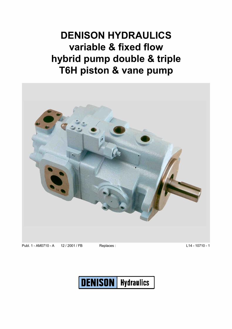
DENISON HYDRAULICSvariable & fixed flow
hybrid pump double & tripleT6H piston & vane pump
CONTENTS
Features........................................................................................................................... 3Instructions ..................................................................................................................... 3Minimum & maximum speeds ....................................................................................... 4Pressure ratings............................................................................................................... 4Priming at starting........................................................................................................... 4Minimum allowable inlet pressure ................................................................................. 5General characteristics.................................................................................................... 5Pump selection : Routine and example .......................................................................... 6Intermittent pressure rating............................................................................................. 6Formulas ......................................................................................................................... 7Description...................................................................................................................... 8Application advantages................................................................................................... 8Controls C, F & L & X................................................................................................... 9Hydraulic fluids ............................................................................................................ 10Shafts ............................................................................................................................ 11
Ordering code & Operating characteristics .................................................................. 12Dimensions ................................................................................................................... 13Technical data ............................................................................................................... 14Technical data ............................................................................................................... 15
Ordering code & Operating characteristics .................................................................. 16Dimensions ................................................................................................................... 17Technical data ............................................................................................................... 18Technical data ............................................................................................................... 19
Ordering code & Operating characteristics .................................................................. 20Dimensions ................................................................................................................... 21Technical data ............................................................................................................... 22
Ordering code & Operating characteristics .................................................................. 23Dimensions ................................................................................................................... 24Technical data ............................................................................................................... 25
Porting diagrams .......................................................................................................... 26Porting diagrams .......................................................................................................... 26Porting diagrams .......................................................................................................... 27
GENERAL
T6H20B - T6H20CT6H20B - T6H20CT6H20BT6H20C
T6H29B - T6H29CT6H29B - T6H29CT6H29BT6H29C
T6H29DT6H29DT6H29D
T6H29DBT6H29DBT6H29DB
T6H20B - T6H20CT6H29B - T6H29C - T6H29DT6H29DB
2
FEATURES
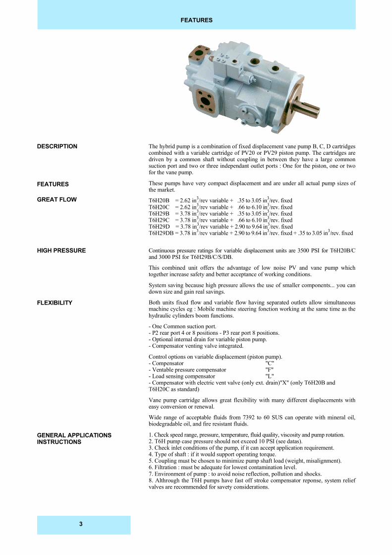
The hybrid pump is a combination of fixed displacement vane pump B, C, D cartridgescombined with a variable cartridge of PV20 or PV29 piston pump. The cartridges aredriven by a common shaft without coupling in between they have a large commonsuction port and two or three independant outlet ports : One for the piston, one or twofor the vane pump.
These pumps have very compact displacement and are under all actual pump sizes ofthe market.
T6H20B = 2.62 in3/rev variable + .35 to 3.05 in3/rev. fixedT6H20C = 2.62 in3/rev variable + .66 to 6.10 in3/rev. fixedT6H29B = 3.78 in3/rev variable + .35 to 3.05 in3/rev. fixedT6H29C = 3.78 in3/rev variable + .66 to 6.10 in3/rev. fixedT6H29D = 3.78 in3/rev variable + 2.90 to 9.64 in3/rev. fixedT6H29DB = 3.78 in3/rev variable + 2.90 to 9.64 in3/rev. fixed + .35 to 3.05 in3/rev. fixed
Continuous pressure ratings for variable displacement units are 3500 PSI for T6H20B/Cand 3000 PSI for T6H29B/C/S/DB.
This combined unit offers the advantage of low noise PV and vane pump whichtogether increase safety and better acceptance of working conditions.
System saving because high pressure allows the use of smaller components... you candown size and gain real savings.
Both units fixed flow and variable flow having separated outlets allow simultaneousmachine cycles eg : Mobile machine steering fonction working at the same time as thehydraulic cylinders boom functions.
- One Common suction port.- P2 rear port 4 or 8 positions - P3 rear port 8 positions.- Optional internal drain for variable piston pump.- Compensator venting valve integrated.
Control options on variable displacement (piston pump).- Compensator "C"- Ventable pressure compensator "F"- Load sensing compensator "L"- Compensator with electric vent valve (only ext. drain)"X" (only T6H20B andT6H20C as standard)
Vane pump cartridge allows great flexibility with many different displacements witheasy conversion or renewal.
Wide range of acceptable fluids from 7392 to 60 SUS can operate with mineral oil,biodegradable oil, and fire resistant fluids.
1. Check speed range, pressure, temperature, fluid quality, viscosity and pump rotation.2. T6H pump case pressure should not exceed 10 PSI (see datas).3. Check inlet conditions of the pump, if it can accept application requirement.4. Type of shaft : if it would support operating torque.5. Coupling must be chosen to minimize pump shaft load (weight, misalignment).6. Filtration : must be adequate for lowest contamination level.7. Environment of pump : to avoid noise reflection, pollution and shocks.8. Althrough the T6H pumps have fast off stroke compensator reponse, system reliefvalves are recommended for savety considerations.
DESCRIPTION
FEATURES
GREAT FLOW
HIGH PRESSURE
FLEXIBILITY
GENERAL APPLICATIONSINSTRUCTIONS
3
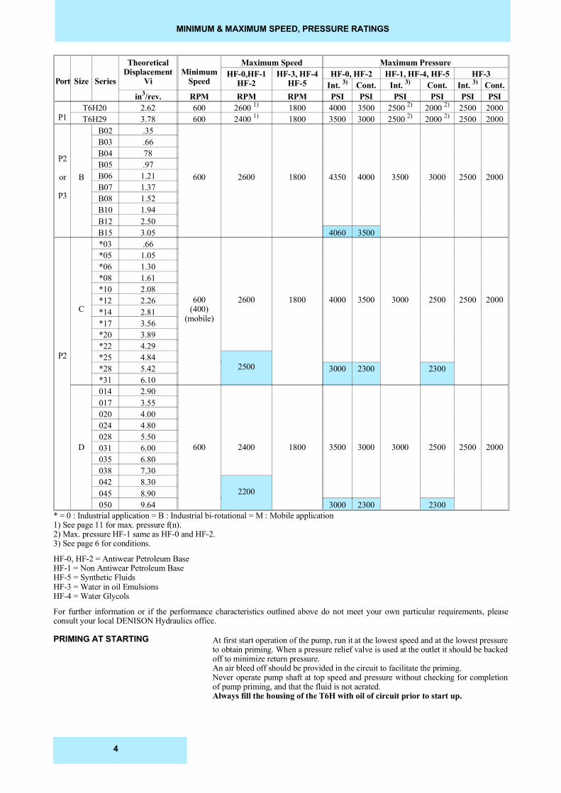
MINIMUM & MAXIMUM SPEED, PRESSURE RATINGS
Port Size Series
TheoreticalDisplacement
ViMinimum
Speed
Maximum Speed Maximum PressureHF-0,HF-1
HF-2HF-3, HF-4
HF-5HF-0, HF-2 HF-1, HF-4, HF-5 HF-3
Int. 3) Cont. Int. 3) Cont. Int. 3) Cont.in3/rev. RPM RPM RPM PSI PSI PSI PSI PSI PSI
P1T6H20 2.62 600 2600 1) 1800 4000 3500 2500 2) 2000 2) 2500 2000T6H29 3.78 600 2400 1) 1800 3500 3000 2500 2) 2000 2) 2500 2000
P2
or
P3
B
B02 .35
600 2600 1800 4350 4000 3500 3000 2500 2000
B03 .66B04 78B05 .97B06 1.21B07 1.37B08 1.52B10 1.94B12 2.50B15 3.05 4060 3500
P2
C
*03 .66
600(400)
(mobile)
2600 1800 4000 3500 3000 2500 2500 2000
*05 1.05*06 1.30*08 1.61*10 2.08*12 2.26*14 2.81*17 3.56*20 3.89*22 4.29*25 4.84
2500*28 5.42 3000 2300 2300*31 6.10
D
014 2.90
600 2400 1800 3500 3000 3000 2500 2500 2000
017 3.55020 4.00024 4.80028 5.50031 6.00035 6.80038 7.30042 8.30
2200045 8.90050 9.64 3000 2300 2300
* = 0 : Industrial application = B : Industrial bi-rotational = M : Mobile application1) See page 11 for max. pressure f(n).2) Max. pressure HF-1 same as HF-0 and HF-2.3) See page 6 for conditions.
HF-0, HF-2 = Antiwear Petroleum BaseHF-1 = Non Antiwear Petroleum BaseHF-5 = Synthetic FluidsHF-3 = Water in oil EmulsionsHF-4 = Water Glycols
For further information or if the performance characteristics outlined above do not meet your own particular requirements, pleaseconsult your local DENISON Hydraulics office.
At first start operation of the pump, run it at the lowest speed and at the lowest pressureto obtain priming. When a pressure relief valve is used at the outlet it should be backedoff to minimize return pressure.An air bleed off should be provided in the circuit to facilitate the priming.Never operate pump shaft at top speed and pressure without checking for completionof pump priming, and that the fluid is not aerated.Always fill the housing of the T6H with oil of circuit prior to start up.
PRIMING AT STARTING
4
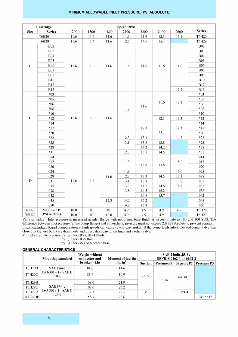
MINIMUM ALLOWABLE INLET PRESSURE (PSI ABSOLUTE)
Cartridge Speed RPMSeriesSize Series 1200 1500 1800 2100 2200 2400 2600
T6H20 11.6 11.6 11.6 11.6 11.6 12.3 13.1 T6H20T6H29 11.6 11.6 11.6 12.5 14.5 15.1 T6H29
B
B02
11.6 11.6 11.6 11.6 11.6 11.6 11.6
B02B03 B03B04 B04B05 B05B06 B06B07 B07B08 B08B10 B10B12 B12B15 12.2 B15
C
*03
11.6 11.6 11.6
11.611.6
11.6 13.1
*03*05 *05*06 *06*08 *08*10 *10*12 12.3 13.3 *12*14
13.8*14
*17 12.313.1
*17*20 *20*22 12.3 13.1 14.2 *22*25 13.1 13.8 13.8 *25*28 14.2 14.2 *28*31 12.3 13.1 14.5 *31
D
014
11.6 11.611.6
11.612.8 13.8
14.5014
017 017020 020024 11.9 16.0 025028 12.3 13.3 14.5 17.1 028031 13.1 13.8 17.8 031035 13.3 14.2 14.8 18.7 035038 13.8 14.5 15.2 038042 14.8 15.7 042045 12.3 14.2 15.2 045050 14.8 15.8 050
T6H20 Max. case P(PSI relative)
10.0 10.0 10. 4.9 4.9 4.9 4.9 T6H20T6H29 10.0 10.0 10.0 4.9 4.9 4.9 T6H29
Vane cartridge : Inlet pressure is measured at inlet flange with petroleum base fluids at viscosity between 60 and 300 SUS. Thedifference between inlet pressure (at the pump flange) and atmospheric pressure must not exceed 2.9 PSI absolute to prevent aeration.Piston cartridge : Rapid compensation at high speeds can cause severe case spikes. If the pump feeds into a blocked center valve thatclose quickly, use both case drain ports and direct short case drain lines and a relief valve.Multiply absolute pressure by 1,25 for HF-3, HF-4 fluids. by 1,35 for HF-5 fluid. by 1,10 for ester or rapeseed base.
GENERAL CHARACTERISTICS
Mounting standardWeight withoutconnector andbracket - Lbs
Moment of inertialb. in2
SAE 4 bolts J518cISO/DIS 6162-1 or 6162-2
Suction Pressure P1 Pressure P2 Pressure P3T6H20B SAE J744c
ISO-3019-1 - SAE B101-2
81.6 14.6
2"1/21"1/4
3/4" or 1"T6H20C 81.6 19.9
T6H29BSAE J744c
ISO-3019-1 - SAE C127-2
108.0 21.9T6H29C 108.0 23.2T6H29D 132.3 27.5 3" 1"1/4
T6H29DB 158.7 28.6 3/4" or 1"
5
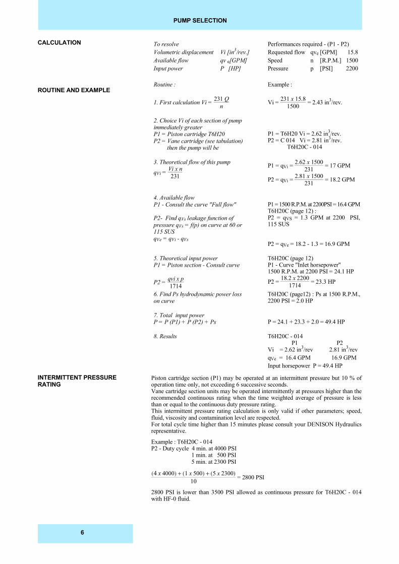
PUMP SELECTION
To resolve Performances required - (P1 - P2)Volumetric displacement Vi [in3/rev.] Requested flow qve [GPM] 15.8Available flow qv e[GPM] Speed n [R.P.M.] 1500Input power P [HP] Pressure p [PSI] 2200
Routine : Example :
1. First calculation Vi = 231 Qn Vi = 231 x 15.8
1500 = 2.43 in3/rev.
2. Choice Vi of each section of pumpimmediately greater P1 = Piston cartridge T6H20P2 = Vane cartridge (see tabulation) then the pump will be
P1 = T6H20 Vi = 2.62 in3/rev.P2 = C 014 Vi = 2.81 in3/rev. T6H20C - 014
3. Theoretical flow of this pump
qVi = Vi x n231
P1 = qVi = 2.62 x 1500231 = 17 GPM
P2 = qVi = 2.81 x 1500231 = 18.2 GPM
4. Available flowP1 - Consult the curve "Full flow"
P2- Find qVs leakage function ofpressure qVs = f(p) on curve at 60 or115 SUSqVe = qVi - qVs
P1 = 1500 R.P.M. at 2200PSI = 16.4 GPMT6H20C (page 12) :P2 = qVS = 1.3 GPM at 2200 PSI,115 SUS
P2 = qVe = 18.2 - 1.3 = 16.9 GPM
5. Theoretical input power P1 = Piston section - Consult curve
P2 = qvi x p1714
T6H20C (page 12)P1 - Curve "Inlet horsepower"1500 R.P.M. at 2200 PSI = 24.1 HP
P2 = 18.2 x 22001714 = 23.3 HP
6. Find Ps hydrodynamic power losson curve
T6H20C (page12) : Ps at 1500 R.P.M.,2200 PSI = 2.0 HP
7. Total input power P = P (P1) + P (P2) + Ps P = 24.1 + 23.3 + 2.0 = 49.4 HP
8. Results T6H20C - 014 P1 P2Vi = 2.62 in3/rev 2.81 in3/revqVe = 16.4 GPM 16.9 GPMInput horsepower P = 49.4 HP
Piston cartridge section (P1) may be operated at an intermittent pressure but 10 % ofoperation time only, not exceeding 6 successive seconds.Vane cartridge section units may be operated intermittently at pressures higher than therecommended continuous rating when the time weighted average of pressure is lessthan or equal to the continuous duty pressure rating.This intermittent pressure rating calculation is only valid if other parameters; speed,fluid, viscosity and contamination level are respected.For total cycle time higher than 15 minutes please consult your DENISON Hydraulicsrepresentative.
Example : T6H20C - 014P2 - Duty cycle 4 min. at 4000 PSI 1 min. at 500 PSI 5 min. at 2300 PSI
�4 x 4000� � �1 x 500� � �5 x 2300�10 = 2800 PSI
2800 PSI is lower than 3500 PSI allowed as continuous pressure for T6H20C - 014with HF-0 fluid.
INTERMITTENT PRESSURERATING
CALCULATION
ROUTINE AND EXAMPLE
6
FORMULAS
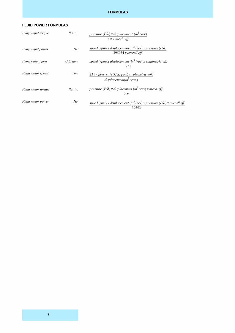
FLUID POWER FORMULAS
Pump input torque lbs. in.
Pump input power HP
Pump output flow U.S. gpm
Fluid motor speed rpm
Fluid motor torque lbs. in.
Fluid motor power HP
pressure �PSI� x displacement �in3 � rev�2 � x mech. eff.
speed �rpm� x displacement �in3 � rev� x pressure �PSI�395934 x overall eff.
speed �rpm� x displacement �in3 � rev� x volumetric eff.231
231 x flow rate �U.S. gpm� x volumetric eff.displacement �in3 � rev.�
pressure �PSI� x displacement �in3 � rev� x mech. eff.2 �
speed �rpm� x displacement �in3 � rev� x pressure �PSI� x overall eff.395934
7
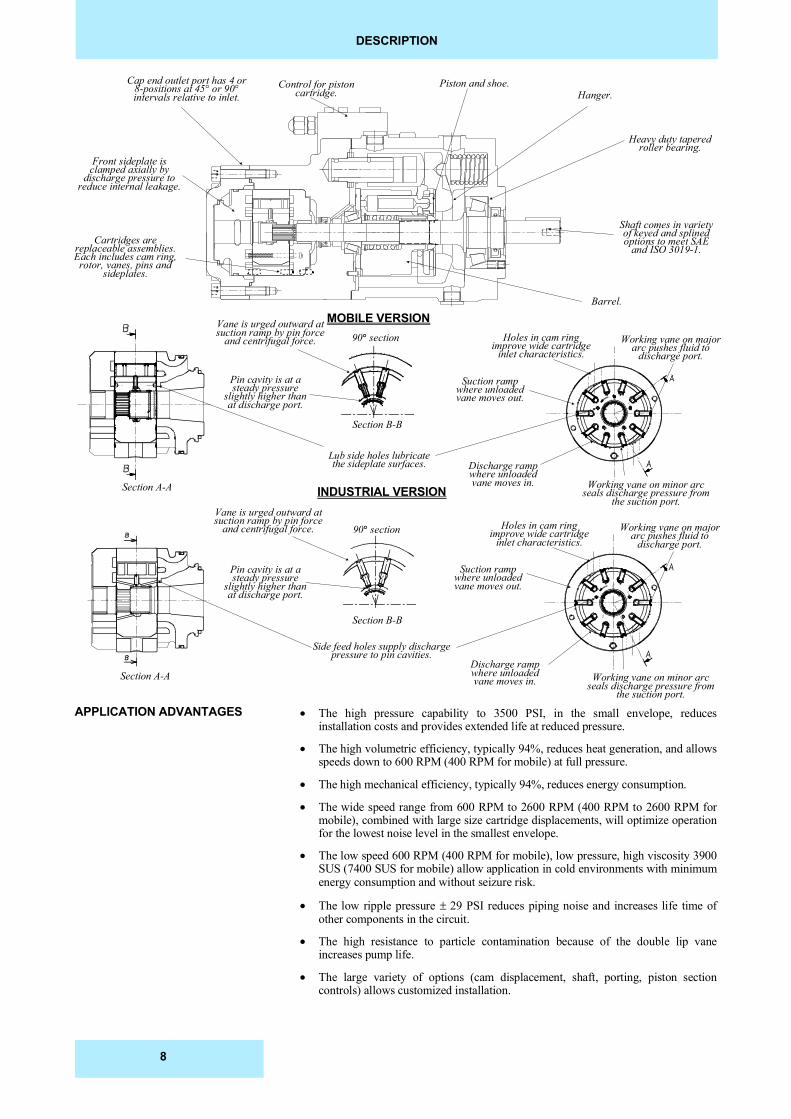
DESCRIPTION
Cap end outlet port has 4 or8-positions at 45° or 90°intervals relative to inlet.
Control for pistoncartridge.
Piston and shoe.
Shaft comes in varietyof keyed and splinedoptions to meet SAE
and ISO 3019-1.
Heavy duty taperedroller bearing.
Front sideplate isclamped axially by
discharge pressure toreduce internal leakage.
Cartridges arereplaceable assemblies.Each includes cam ring,rotor, vanes, pins and
sideplates.
Hanger.
Vane is urged outward atsuction ramp by pin force
and centrifugal force. 90� section Holes in cam ringimprove wide cartridge
inlet characteristics.Working vane on major
arc pushes fluid todischarge port.
Suction rampwhere unloadedvane moves out.
Section B-B
Section A-A
Pin cavity is at asteady pressure
slightly higher thanat discharge port.
Discharge rampwhere unloadedvane moves in.
Lub side holes lubricatethe sideplate surfaces.
Working vane on minor arcseals discharge pressure from
the suction port.
Barrel.
INDUSTRIAL VERSION
MOBILE VERSION
Section B-B
90� section
Section A-A
Vane is urged outward atsuction ramp by pin force
and centrifugal force. Holes in cam ringimprove wide cartridge
inlet characteristics.Working vane on major
arc pushes fluid todischarge port.
Suction rampwhere unloadedvane moves out.
Pin cavity is at asteady pressure
slightly higher thanat discharge port.
Discharge rampwhere unloadedvane moves in.
Side feed holes supply dischargepressure to pin cavities.
Working vane on minor arcseals discharge pressure from
the suction port.
� The high pressure capability to 3500 PSI, in the small envelope, reducesinstallation costs and provides extended life at reduced pressure.
� The high volumetric efficiency, typically 94%, reduces heat generation, and allowsspeeds down to 600 RPM (400 RPM for mobile) at full pressure.
� The high mechanical efficiency, typically 94%, reduces energy consumption.
� The wide speed range from 600 RPM to 2600 RPM (400 RPM to 2600 RPM formobile), combined with large size cartridge displacements, will optimize operationfor the lowest noise level in the smallest envelope.
� The low speed 600 RPM (400 RPM for mobile), low pressure, high viscosity 3900SUS (7400 SUS for mobile) allow application in cold environments with minimumenergy consumption and without seizure risk.
� The low ripple pressure�� 29 PSI reduces piping noise and increases life time ofother components in the circuit.
� The high resistance to particle contamination because of the double lip vaneincreases pump life.
� The large variety of options (cam displacement, shaft, porting, piston sectioncontrols) allows customized installation.
APPLICATION ADVANTAGES
8
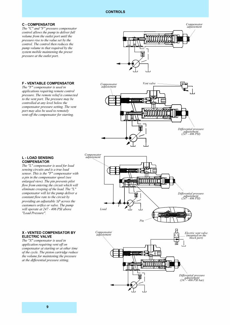
C - COMPENSATORThe "C" and "F" pressure compensatorcontrol allows the pump to deliver fullvolume from the outlet port until thepressure rise to the value set by thecontrol. The control then reduces thepump volume to that required by thesystem mobile maintening the presetpressure at the outlet port.
F - VENTABLE COMPENSATORThe "F" compensator is used inapplications requiring remote controlpressure. The remote relief is connectedto the vent port. The pressure may becontrolled at any level below thecompensator pressure setting. The ventport may also be used to remotelyvent-off the compensator for starting.
L - LOAD SENSINGCOMPENSATORThe "L" compensator is used for loadsensing circuits and is a true loadsensor. This is the "F" compensator witha pin in the compensator spool (seeenlarged view). The pin prevents pilotflow from entering the circuit which willeliminate creeping of the load. The "L"compensator will let the pump deliver aconstant flow rate to the circuit byproviding an adjustable P across thecustomers orifice or valve. The pumpwill operate at 247 - 406 PSI above"Load Pressure".
X - VENTED COMPENSATOR BYELECTRIC VALVEThe "X" compensator is used inapplication requiring vent off oncompensator at starting or at other timeof the cycle. The piston cartridge reducethe volume for maintening the pressureat the differential pressure sitting.
CONTROLS
Compensatoradjustement
Compensatoradjustement
Vent valve
Differential pressureadjustement
(247 - 406 PSI)
Compensatoradjustement
Differential pressureadjustement
(247 - 406 PSI)
Load
Pin
Compensatoradjustement
Differential pressureadjustement
(247 - 406 PSI bar)
Electric vent valve(mounted on the
block port)
9
HYDRAULIC FLUIDS
FLUIDSRECOMMENDED FLUIDS
ACCEPTABLE ALTERNATEFLUIDS
VISCOSITY
VISCOSITY INDEX
FLUID CLEANLINESS
OPERATING TEMPERATURESAND VISCOSITIES
WATER CONTAMINATION INTHE FLUID
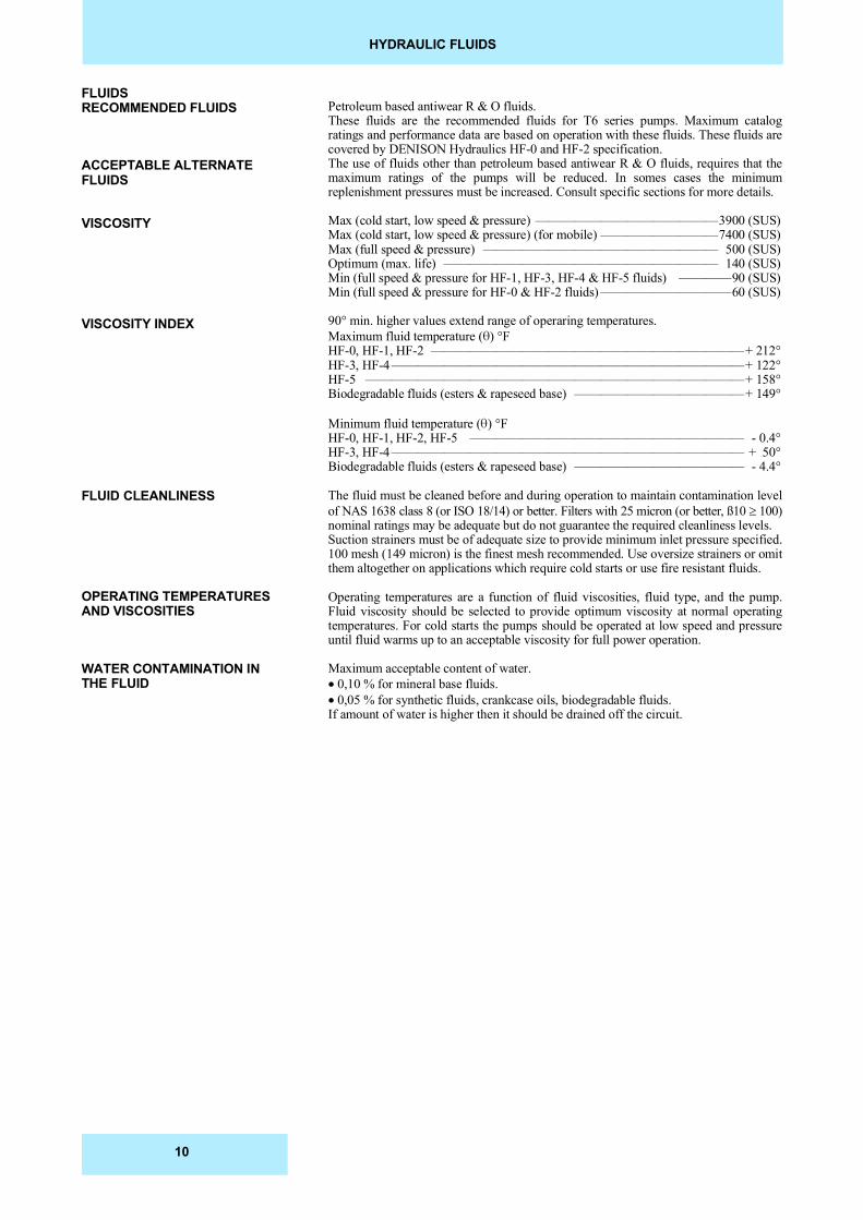
Petroleum based antiwear R & O fluids.These fluids are the recommended fluids for T6 series pumps. Maximum catalogratings and performance data are based on operation with these fluids. These fluids arecovered by DENISON Hydraulics HF-0 and HF-2 specification.The use of fluids other than petroleum based antiwear R & O fluids, requires that themaximum ratings of the pumps will be reduced. In somes cases the minimumreplenishment pressures must be increased. Consult specific sections for more details.
Max (cold start, low speed & pressure) ——————————————3900 (SUS)Max (cold start, low speed & pressure) (for mobile) —————————7400 (SUS)Max (full speed & pressure) —————————————————— 500 (SUS)Optimum (max. life) ————————————————————— 140 (SUS)Min (full speed & pressure for HF-1, HF-3, HF-4 & HF-5 fluids) ————90 (SUS)Min (full speed & pressure for HF-0 & HF-2 fluids) ——————————60 (SUS)
90° min. higher values extend range of operaring temperatures.Maximum fluid temperature () °FHF-0, HF-1, HF-2 ————————————————————————+ 212°HF-3, HF-4 ———————————————————————————+ 122°HF-5 —————————————————————————————+ 158°Biodegradable fluids (esters & rapeseed base) —————————————+ 149°
Minimum fluid temperature () °FHF-0, HF-1, HF-2, HF-5 ————————————————————— - 0.4°HF-3, HF-4 ——————————————————————————— + 50°Biodegradable fluids (esters & rapeseed base) ————————————— - 4.4°
The fluid must be cleaned before and during operation to maintain contamination levelof NAS 1638 class 8 (or ISO 18/14) or better. Filters with 25 micron (or better, ß10 � 100)nominal ratings may be adequate but do not guarantee the required cleanliness levels.Suction strainers must be of adequate size to provide minimum inlet pressure specified.100 mesh (149 micron) is the finest mesh recommended. Use oversize strainers or omitthem altogether on applications which require cold starts or use fire resistant fluids.
Operating temperatures are a function of fluid viscosities, fluid type, and the pump.Fluid viscosity should be selected to provide optimum viscosity at normal operatingtemperatures. For cold starts the pumps should be operated at low speed and pressureuntil fluid warms up to an acceptable viscosity for full power operation.
Maximum acceptable content of water.��0,10 % for mineral base fluids.� 0,05 % for synthetic fluids, crankcase oils, biodegradable fluids.If amount of water is higher then it should be drained off the circuit.
10
SHAFTS
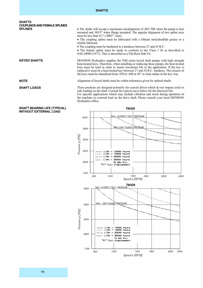
� The shafts will accept a maximum misalignment of .003 TIR when the pump is footmounted and .0015" when flange mounted. The angular alignment of two spline axesmust be less than 0,1° (.0001" /mm).� The coupling spline must be lubricated with a lithium molydisulfide grease or asimilar lubricant.� The coupling must be hardened to a hardness between 27 and 45 R.C.� The female spline must be made to conform to the Class 1 fit as described inSAE-J498b (1971). This is described as a Flat Root Side Fit.
DENISON Hydraulics supplies the T6H series keyed shaft pumps with high strengthheat-treated keys. Therefore, when installing or replacing these pumps, the heat-treatedkeys must be used in order to insure maximum life in the application. If the key isreplaced it must be a heat-treated key between 27 and 34 R.C. hardness. The corners ofthe keys must be chamfered from .030 to .040 at 45° to clear radius in the key way.
Alignment of keyed shafts must be within tolerances given for splined shafts.
These products are designed primarily for coaxial drives which do not impose axial orside loading on the shaft. Consult the typical curve below for the theorical life.For specific applications which may include vibration and stock during operation ofthe machine or external load on the drive shaft. Please consult your local DENISONHydraulics office.
SHAFTSCOUPLINGS AND FEMALE SPLINESSPLINES
KEYED SHAFTS
NOTE
SHAFT LOADS
Pres
sure
p [P
SI]
Speed n [RPM]
Pres
sure
p [P
SI]
Speed n [RPM]
T6H20
T6H29
SHAFT BEARING LIFE (TYPICAL)WITHOUT EXTERNAL LOAD
11
ORDERING CODE & OPERATING CHARACTERISTICS - T6H20B - T6H20C SERIES
OPERATING CHARACTERISTICS - TYPICAL [115 SUS]
* = 0 = Indust. uni-rotational / B = Indust. bi-rotational / M = Mobile bi-rotational
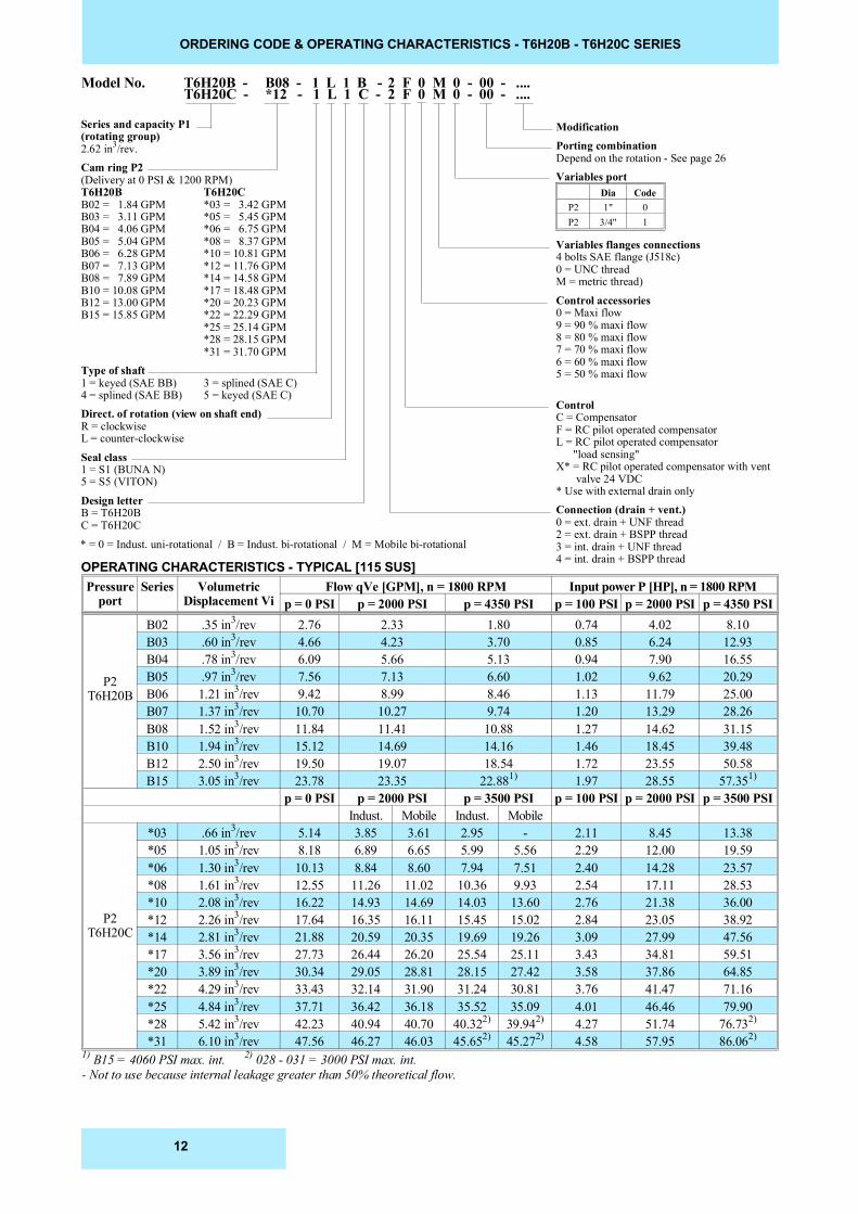
Model No. T6H20B - B08 - 1 L 1 B - 2 F 0 M 0 - 00 - ....
Series and capacity P1(rotating group)2.62 in3/rev.Cam ring P2(Delivery at 0 PSI & 1200 RPM)T6H20B T6H20CB02 = 1.84 GPM *03 = 3.42 GPMB03 = 3.11 GPM *05 = 5.45 GPMB04 = 4.06 GPM *06 = 6.75 GPMB05 = 5.04 GPM *08 = 8.37 GPMB06 = 6.28 GPM *10 = 10.81 GPMB07 = 7.13 GPM *12 = 11.76 GPMB08 = 7.89 GPM *14 = 14.58 GPMB10 = 10.08 GPM *17 = 18.48 GPMB12 = 13.00 GPM *20 = 20.23 GPMB15 = 15.85 GPM *22 = 22.29 GPM
*25 = 25.14 GPM*28 = 28.15 GPM*31 = 31.70 GPM
Type of shaft1 = keyed (SAE BB) 3 = splined (SAE C)4 = splined (SAE BB) 5 = keyed (SAE C)Direct. of rotation (view on shaft end)R = clockwiseL = counter-clockwise
Seal class1 = S1 (BUNA N)5 = S5 (VITON)
Design letterB = T6H20BC = T6H20C
ModificationPorting combinationDepend on the rotation - See page 26Variables port
Variables flanges connections4 bolts SAE flange (J518c)0 = UNC threadM = metric thread)
Control accessories0 = Maxi flow9 = 90 % maxi flow8 = 80 % maxi flow7 = 70 % maxi flow6 = 60 % maxi flow5 = 50 % maxi flow
ControlC = CompensatorF = RC pilot operated compensatorL = RC pilot operated compensator "load sensing"X* = RC pilot operated compensator with vent valve 24 VDC* Use with external drain onlyConnection (drain + vent.)0 = ext. drain + UNF thread2 = ext. drain + BSPP thread3 = int. drain + UNF thread4 = int. drain + BSPP thread
T6H20C - *12 - 1 L 1 C - 2 F 0 M 0 - 00 - ....
Pressureport
Series VolumetricDisplacement Vi
Flow qVe [GPM], n = 1800 RPM Input power P [HP], n = 1800 RPM p = 0 PSI p = 2000 PSI p = 4350 PSI p = 100 PSI p = 2000 PSI p = 4350 PSI
P2T6H20B
B02 .35 in3/rev 2.76 2.33 1.80 0.74 4.02 8.10B03 .60 in3/rev 4.66 4.23 3.70 0.85 6.24 12.93B04 .78 in3/rev 6.09 5.66 5.13 0.94 7.90 16.55B05 .97 in3/rev 7.56 7.13 6.60 1.02 9.62 20.29B06 1.21 in3/rev 9.42 8.99 8.46 1.13 11.79 25.00B07 1.37 in3/rev 10.70 10.27 9.74 1.20 13.29 28.26B08 1.52 in3/rev 11.84 11.41 10.88 1.27 14.62 31.15B10 1.94 in3/rev 15.12 14.69 14.16 1.46 18.45 39.48B12 2.50 in3/rev 19.50 19.07 18.54 1.72 23.55 50.58B15 3.05 in3/rev 23.78 23.35 22.881) 1.97 28.55 57.351)
p = 0 PSI p = 2000 PSI p = 3500 PSI p = 100 PSI p = 2000 PSI p = 3500 PSIIndust. Mobile Indust. Mobile
P2T6H20C
*03 .66 in3/rev 5.14 3.85 3.61 2.95 - 2.11 8.45 13.38*05 1.05 in3/rev 8.18 6.89 6.65 5.99 5.56 2.29 12.00 19.59*06 1.30 in3/rev 10.13 8.84 8.60 7.94 7.51 2.40 14.28 23.57*08 1.61 in3/rev 12.55 11.26 11.02 10.36 9.93 2.54 17.11 28.53*10 2.08 in3/rev 16.22 14.93 14.69 14.03 13.60 2.76 21.38 36.00*12 2.26 in3/rev 17.64 16.35 16.11 15.45 15.02 2.84 23.05 38.92*14 2.81 in3/rev 21.88 20.59 20.35 19.69 19.26 3.09 27.99 47.56*17 3.56 in3/rev 27.73 26.44 26.20 25.54 25.11 3.43 34.81 59.51*20 3.89 in3/rev 30.34 29.05 28.81 28.15 27.42 3.58 37.86 64.85*22 4.29 in3/rev 33.43 32.14 31.90 31.24 30.81 3.76 41.47 71.16*25 4.84 in3/rev 37.71 36.42 36.18 35.52 35.09 4.01 46.46 79.90*28 5.42 in3/rev 42.23 40.94 40.70 40.322) 39.942) 4.27 51.74 76.732)
*31 6.10 in3/rev 47.56 46.27 46.03 45.652) 45.272) 4.58 57.95 86.062)
1) B15 = 4060 PSI max. int. 2) 028 - 031 = 3000 PSI max. int.- Not to use because internal leakage greater than 50% theoretical flow.
Dia CodeP2 1" 0P2 3/4" 1
12
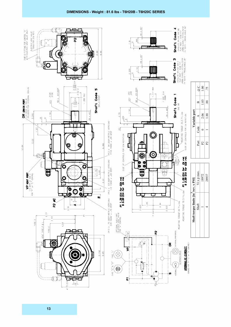
DIMENSIONS - Weight : 81.6 lbs - T6H20B - T6H20C SERIES
Var
iabl
e po
rt
��C
1.00 .75
B 1.03 .88
A 2.06
1.88
Cod
e0 1
Port
P2 P2
Shaf
t tor
que
limits
[in3 /r
ev. x
PSI
]V
i x p
max
.18
972
2893
7
Shaf
t1 4
13
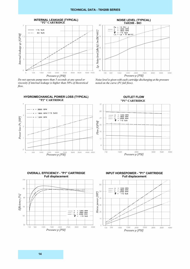
TECHNICAL DATA - T6H20B SERIES
T6H20B - B03
OVERALL EFFICIENCY - "P1" CARTRIDGEFull displacement
INPUT HORSEPOWER - "P1" CARTRIDGEFull displacement
HYDROMECHANICAL POWER LOSS (TYPICAL) OUTLET FLOW
Effic
ienc
y [%
]
Hor
se p
ower
[HP]
Flow
[GPM
]
Powe
r los
s Ps [
HP]
Pressure p [PSI] Pressure p [PSI]
Pressure p [PSI]Pressure p [PSI]
INTERNAL LEAKAGE (TYPICAL) NOISE LEVEL (TYPICAL)
Lp. N
oise
leve
l [db
(A)]
1m IS
O 44
12
Inte
rnal
leak
age q
s [G
PM]
Pressure p [PSI]Pressure p [PSI]
"P2" CARTRIDGE
Do not operate pump more than 5 seconds at any speed orviscosity if internal leakage is higher than 50% of theoreticalflow.
Noise level is given with each cartridge discharging at the pressurenoted on the curve (P1 full flow).
"P1" CARTRIDGE"P2" CARTRIDGE
14
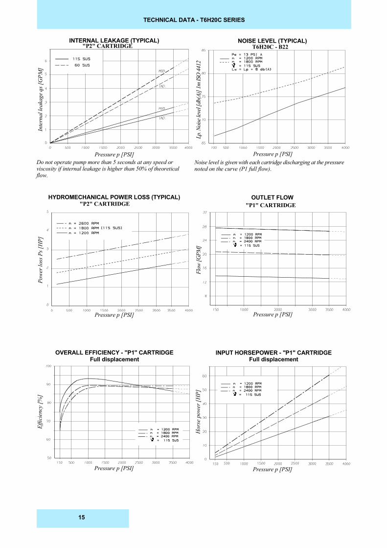
TECHNICAL DATA - T6H20C SERIES
HYDROMECHANICAL POWER LOSS (TYPICAL)
Effic
ienc
y [%
]
Flow
[GPM
]
Pressure p [PSI]
Pressure p [PSI]Pressure p [PSI]
Lp. N
oise
leve
l [db
(A)]
1m IS
O 44
12
Inte
rnal
leak
age q
s [G
PM]
Pressure p [PSI]Pressure p [PSI]Do not operate pump more than 5 seconds at any speed orviscosity if internal leakage is higher than 50% of theoreticalflow.
OVERALL EFFICIENCY - "P1" CARTRIDGEFull displacement
Hor
se p
ower
[HP]
Pressure p [PSI]
"P1" CARTRIDGE"P2" CARTRIDGE
T6H20C - B22INTERNAL LEAKAGE (TYPICAL) NOISE LEVEL (TYPICAL)
"P2" CARTRIDGE
INPUT HORSEPOWER - "P1" CARTRIDGEFull displacement
OUTLET FLOW
Noise level is given with each cartridge discharging at the pressurenoted on the curve (P1 full flow).
Powe
r los
s Ps [
HP]
15
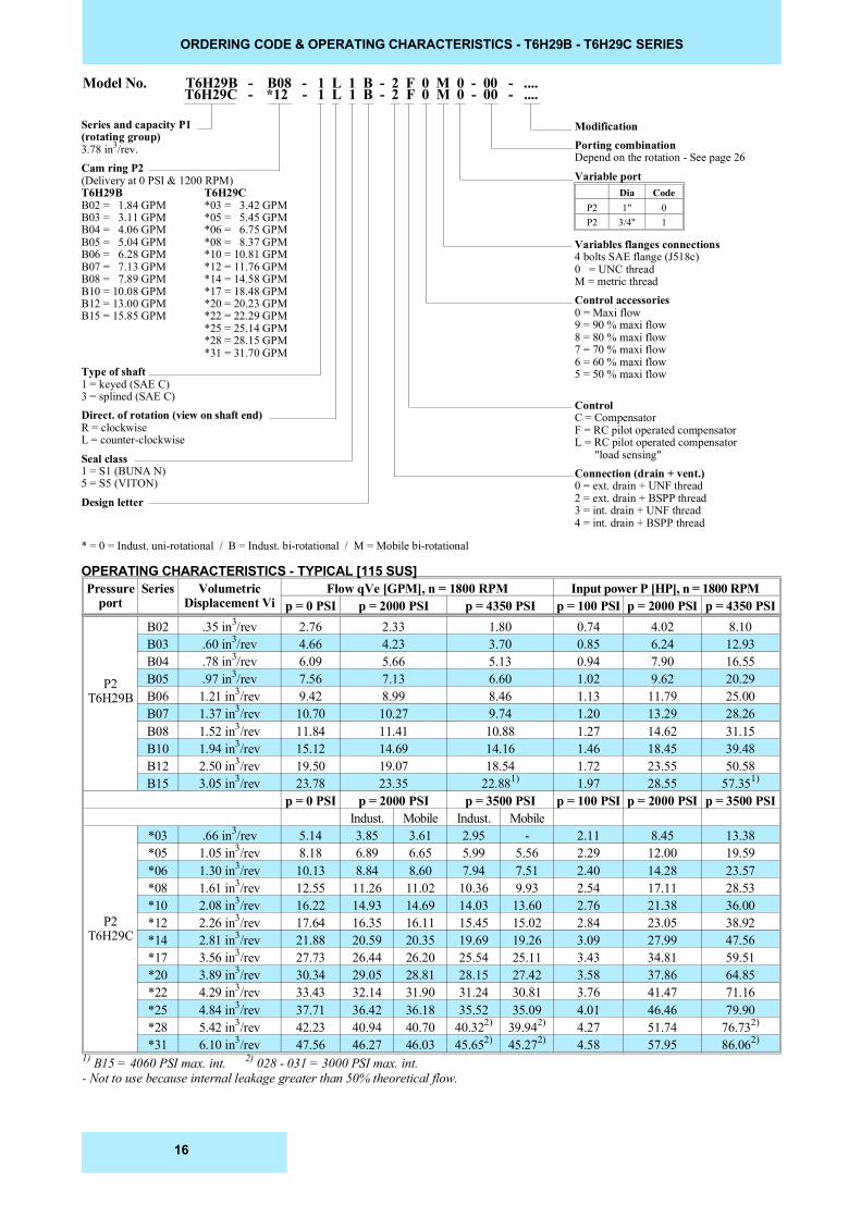
ORDERING CODE & OPERATING CHARACTERISTICS - T6H29B - T6H29C SERIES
Series and capacity P1(rotating group)3.78 in3/rev.Cam ring P2(Delivery at 0 PSI & 1200 RPM)T6H29B T6H29CB02 = 1.84 GPM *03 = 3.42 GPMB03 = 3.11 GPM *05 = 5.45 GPMB04 = 4.06 GPM *06 = 6.75 GPMB05 = 5.04 GPM *08 = 8.37 GPMB06 = 6.28 GPM *10 = 10.81 GPMB07 = 7.13 GPM *12 = 11.76 GPMB08 = 7.89 GPM *14 = 14.58 GPMB10 = 10.08 GPM *17 = 18.48 GPMB12 = 13.00 GPM *20 = 20.23 GPMB15 = 15.85 GPM *22 = 22.29 GPM
*25 = 25.14 GPM*28 = 28.15 GPM*31 = 31.70 GPM
Type of shaft1 = keyed (SAE C)3 = splined (SAE C)Direct. of rotation (view on shaft end)R = clockwiseL = counter-clockwise
Seal class1 = S1 (BUNA N)5 = S5 (VITON)
Design letter
ModificationPorting combinationDepend on the rotation - See page 26
Variable port
Variables flanges connections4 bolts SAE flange (J518c)0 = UNC threadM = metric threadControl accessories0 = Maxi flow9 = 90 % maxi flow8 = 80 % maxi flow7 = 70 % maxi flow6 = 60 % maxi flow5 = 50 % maxi flow
ControlC = CompensatorF = RC pilot operated compensatorL = RC pilot operated compensator "load sensing"Connection (drain + vent.)0 = ext. drain + UNF thread2 = ext. drain + BSPP thread3 = int. drain + UNF thread4 = int. drain + BSPP thread
Model No. T6H29B - B08 - 1 L 1 B - 2 F 0 M 0 - 00 - ....T6H29C - *12 - 1 L 1 B - 2 F 0 M 0 - 00 - ....
OPERATING CHARACTERISTICS - TYPICAL [115 SUS]
* = 0 = Indust. uni-rotational / B = Indust. bi-rotational / M = Mobile bi-rotational
Dia CodeP2 1" 0P2 3/4" 1
Pressureport
Series VolumetricDisplacement Vi
Flow qVe [GPM], n = 1800 RPM Input power P [HP], n = 1800 RPM p = 0 PSI p = 2000 PSI p = 4350 PSI p = 100 PSI p = 2000 PSI p = 4350 PSI
P2T6H29B
B02 .35 in3/rev 2.76 2.33 1.80 0.74 4.02 8.10B03 .60 in3/rev 4.66 4.23 3.70 0.85 6.24 12.93B04 .78 in3/rev 6.09 5.66 5.13 0.94 7.90 16.55B05 .97 in3/rev 7.56 7.13 6.60 1.02 9.62 20.29B06 1.21 in3/rev 9.42 8.99 8.46 1.13 11.79 25.00B07 1.37 in3/rev 10.70 10.27 9.74 1.20 13.29 28.26B08 1.52 in3/rev 11.84 11.41 10.88 1.27 14.62 31.15B10 1.94 in3/rev 15.12 14.69 14.16 1.46 18.45 39.48B12 2.50 in3/rev 19.50 19.07 18.54 1.72 23.55 50.58B15 3.05 in3/rev 23.78 23.35 22.881) 1.97 28.55 57.351)
p = 0 PSI p = 2000 PSI p = 3500 PSI p = 100 PSI p = 2000 PSI p = 3500 PSIIndust. Mobile Indust. Mobile
P2T6H29C
*03 .66 in3/rev 5.14 3.85 3.61 2.95 - 2.11 8.45 13.38*05 1.05 in3/rev 8.18 6.89 6.65 5.99 5.56 2.29 12.00 19.59*06 1.30 in3/rev 10.13 8.84 8.60 7.94 7.51 2.40 14.28 23.57*08 1.61 in3/rev 12.55 11.26 11.02 10.36 9.93 2.54 17.11 28.53*10 2.08 in3/rev 16.22 14.93 14.69 14.03 13.60 2.76 21.38 36.00*12 2.26 in3/rev 17.64 16.35 16.11 15.45 15.02 2.84 23.05 38.92*14 2.81 in3/rev 21.88 20.59 20.35 19.69 19.26 3.09 27.99 47.56*17 3.56 in3/rev 27.73 26.44 26.20 25.54 25.11 3.43 34.81 59.51*20 3.89 in3/rev 30.34 29.05 28.81 28.15 27.42 3.58 37.86 64.85*22 4.29 in3/rev 33.43 32.14 31.90 31.24 30.81 3.76 41.47 71.16*25 4.84 in3/rev 37.71 36.42 36.18 35.52 35.09 4.01 46.46 79.90*28 5.42 in3/rev 42.23 40.94 40.70 40.322) 39.942) 4.27 51.74 76.732)
*31 6.10 in3/rev 47.56 46.27 46.03 45.652) 45.272) 4.58 57.95 86.062)
1) B15 = 4060 PSI max. int. 2) 028 - 031 = 3000 PSI max. int.- Not to use because internal leakage greater than 50% theoretical flow.
16
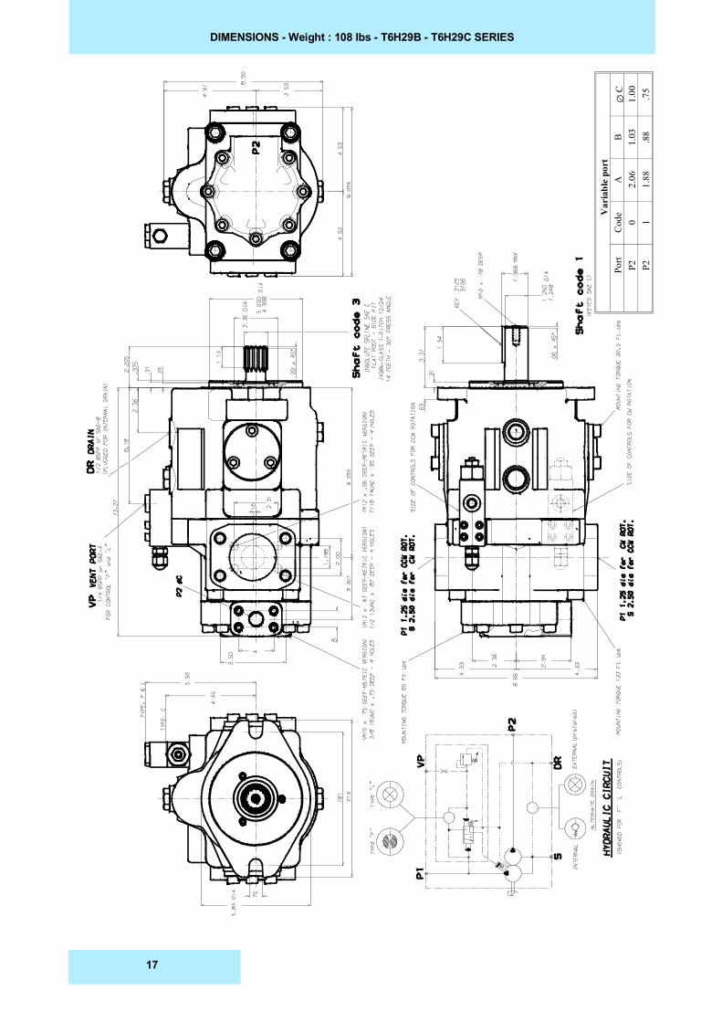
DIMENSIONS - Weight : 108 lbs - T6H29B - T6H29C SERIES
Var
iabl
e po
rt
��C
1.00 .75
B 1.03 .88
A 2.06
1.88
Cod
e0 1
Port
P2 P2
17
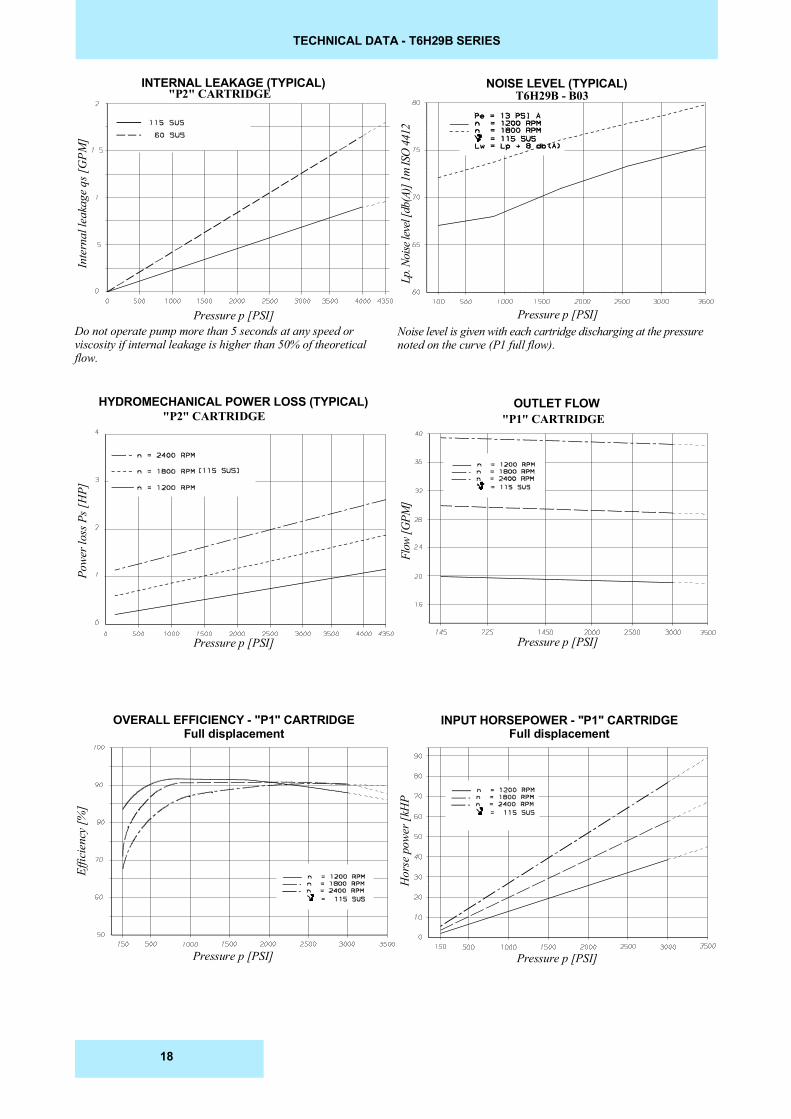
TECHNICAL DATA - T6H29B SERIES
HYDROMECHANICAL POWER LOSS (TYPICAL)
Effic
ienc
y [%
]
Flow
[GPM
]
Pressure p [PSI]
Pressure p [PSI]Pressure p [PSI]
Lp. N
oise
leve
l [db
(A)]
1m IS
O 44
12
Inte
rnal
leak
age q
s [G
PM]
Pressure p [PSI]Pressure p [PSI]Do not operate pump more than 5 seconds at any speed orviscosity if internal leakage is higher than 50% of theoreticalflow.
OVERALL EFFICIENCY - "P1" CARTRIDGEFull displacement
Hor
se p
ower
[kH
P
Pressure p [PSI]
"P1" CARTRIDGE"P2" CARTRIDGE
T6H29B - B03INTERNAL LEAKAGE (TYPICAL) NOISE LEVEL (TYPICAL)
"P2" CARTRIDGE
INPUT HORSEPOWER - "P1" CARTRIDGEFull displacement
OUTLET FLOW
Noise level is given with each cartridge discharging at the pressurenoted on the curve (P1 full flow).
Powe
r los
s Ps [
HP]
18
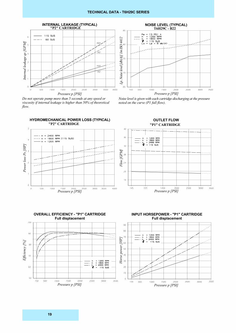
TECHNICAL DATA - T6H29C SERIES
HYDROMECHANICAL POWER LOSS (TYPICAL)
Effic
ienc
y [%
]
Flow
[GPM
]
Pressure p [PSI]
Pressure p [PSI]Pressure p [PSI]
Lp. N
oise
leve
l [db
(A)]
1m IS
O 44
12
Inte
rnal
leak
age q
s [G
PM]
Pressure p [PSI]Pressure p [PSI]Do not operate pump more than 5 seconds at any speed orviscosity if internal leakage is higher than 50% of theoreticalflow.
OVERALL EFFICIENCY - "P1" CARTRIDGEFull displacement
Hor
se p
ower
[HP]
Pressure p [PSI]
"P1" CARTRIDGE"P2" CARTRIDGE
T6H29C - B22INTERNAL LEAKAGE (TYPICAL) NOISE LEVEL (TYPICAL)
"P2" CARTRIDGE
INPUT HORSEPOWER - "P1" CARTRIDGEFull displacement
OUTLET FLOW
Noise level is given with each cartridge discharging at the pressurenoted on the curve (P1 full flow).
Powe
r los
s Ps [
HP]
19
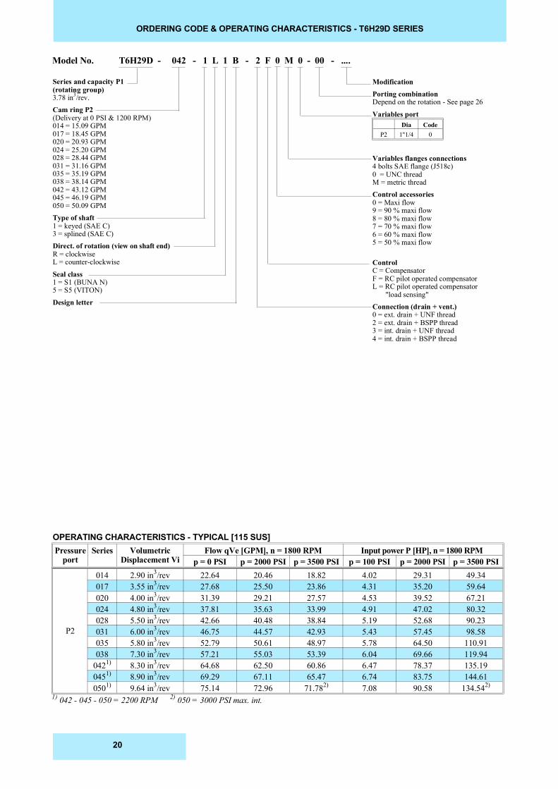
ORDERING CODE & OPERATING CHARACTERISTICS - T6H29D SERIES
Model No. T6H29D - 042 - 1 L 1 B - 2 F 0 M 0 - 00 - ....
Series and capacity P1(rotating group)3.78 in3/rev.Cam ring P2(Delivery at 0 PSI & 1200 RPM)014 = 15.09 GPM017 = 18.45 GPM020 = 20.93 GPM024 = 25.20 GPM028 = 28.44 GPM031 = 31.16 GPM035 = 35.19 GPM038 = 38.14 GPM042 = 43.12 GPM045 = 46.19 GPM050 = 50.09 GPMType of shaft1 = keyed (SAE C)3 = splined (SAE C)Direct. of rotation (view on shaft end)R = clockwiseL = counter-clockwise
Seal class1 = S1 (BUNA N)5 = S5 (VITON)
Design letter
OPERATING CHARACTERISTICS - TYPICAL [115 SUS]
ModificationPorting combinationDepend on the rotation - See page 26
Variables port
Variables flanges connections4 bolts SAE flange (J518c)0 = UNC threadM = metric threadControl accessories0 = Maxi flow9 = 90 % maxi flow8 = 80 % maxi flow7 = 70 % maxi flow6 = 60 % maxi flow5 = 50 % maxi flow
ControlC = CompensatorF = RC pilot operated compensatorL = RC pilot operated compensator "load sensing"Connection (drain + vent.)0 = ext. drain + UNF thread2 = ext. drain + BSPP thread3 = int. drain + UNF thread4 = int. drain + BSPP thread
Pressureport
Series VolumetricDisplacement Vi
Flow qVe [GPM], n = 1800 RPM Input power P [HP], n = 1800 RPM p = 0 PSI p = 2000 PSI p = 3500 PSI p = 100 PSI p = 2000 PSI p = 3500 PSI
P2
014 2.90 in3/rev 22.64 20.46 18.82 4.02 29.31 49.34017 3.55 in3/rev 27.68 25.50 23.86 4.31 35.20 59.64020 4.00 in3/rev 31.39 29.21 27.57 4.53 39.52 67.21024 4.80 in3/rev 37.81 35.63 33.99 4.91 47.02 80.32028 5.50 in3/rev 42.66 40.48 38.84 5.19 52.68 90.23031 6.00 in3/rev 46.75 44.57 42.93 5.43 57.45 98.58035 5.80 in3/rev 52.79 50.61 48.97 5.78 64.50 110.91038 7.30 in3/rev 57.21 55.03 53.39 6.04 69.66 119.94
0421) 8.30 in3/rev 64.68 62.50 60.86 6.47 78.37 135.190451) 8.90 in3/rev 69.29 67.11 65.47 6.74 83.75 144.610501) 9.64 in3/rev 75.14 72.96 71.782) 7.08 90.58 134.542)
1) 042 - 045 - 050 = 2200 RPM 2) 050 = 3000 PSI max. int.
Dia CodeP2 1"1/4 0
20
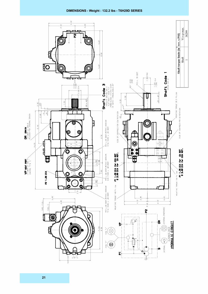
DIMENSIONS - Weight : 132.2 lbs - T6H29D SERIES
Shaf
t tor
que
limits
[in3 /r
ev. x
PSI
]V
i x p
max
.38
299
Shaf
t1
21
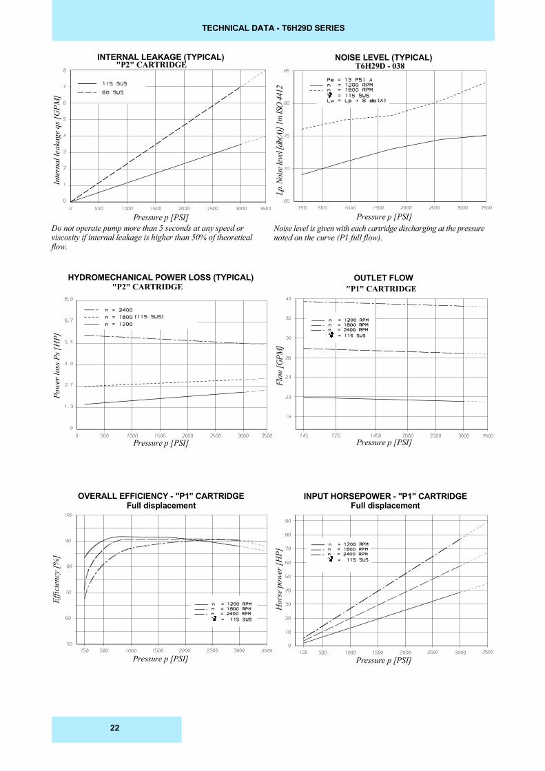
TECHNICAL DATA - T6H29D SERIES
HYDROMECHANICAL POWER LOSS (TYPICAL)
Effic
ienc
y [%
]
Flow
[GPM
]
Pressure p [PSI]
Pressure p [PSI]Pressure p [PSI]
Lp. N
oise
leve
l [db
(A)]
1m IS
O 44
12
Inte
rnal
leak
age q
s [G
PM]
Pressure p [PSI]Pressure p [PSI]Do not operate pump more than 5 seconds at any speed orviscosity if internal leakage is higher than 50% of theoreticalflow.
OVERALL EFFICIENCY - "P1" CARTRIDGEFull displacement
Hor
se p
ower
[HP]
Pressure p [PSI]
"P1" CARTRIDGE"P2" CARTRIDGE
T6H29D - 038INTERNAL LEAKAGE (TYPICAL) NOISE LEVEL (TYPICAL)
"P2" CARTRIDGE
INPUT HORSEPOWER - "P1" CARTRIDGEFull displacement
OUTLET FLOW
Noise level is given with each cartridge discharging at the pressurenoted on the curve (P1 full flow).
Powe
r los
s Ps [
HP]
22
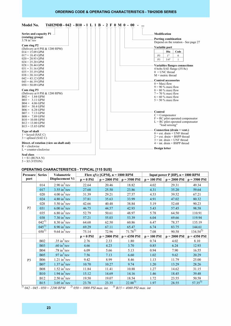
ORDERING CODE & OPERATING CHARACTERISTICS - T6H29DB SERIES
Model No. T6H29DB - 042 - B10 - 1 L 1 B - 2 F 0 M 0 - 00 - ...
Series and capacity P1(rotating group)3.78 in3/revCam ring P2(Delivery at 0 PSI & 1200 RPM)014 = 15.09 GPM017 = 18.45 GPM020 = 20.93 GPM024 = 25.20 GPM028 = 28.44 GPM031 = 31.16 GPM035 = 35.19 GPM038 = 38.14 GPM042 = 43.12 GPM045 = 46.19 GPM050 = 50.09 GPM Cam ring P3(Delivery at 0 PSI & 1200 RPM)B02 = 1.84 GPMB03 = 3.11 GPMB04 = 4.06 GPMB05 = 50.4 GPMB06 = 6.28 GPMB07 = 7.13 GPMB08 = 7.89 GPMB10 = 10.08 GPMB12 = 13.00 GPMB15 = 15.85 GPMType of shaft1 = keyed (SAE C)3 = splined (SAE C)Direct. of rotation (view on shaft end)R = clockwiseL = counter-clockwise
Seal class1 = S1 (BUNA N)5 = S5 (VITON)
OPERATING CHARACTERISTICS - TYPICAL [115 SUS]
ModificationPorting combinationDepend on the rotation - See page 27
Variable port
Variables flanges connections4 bolts SAE flange (J518c)0 = UNC threadM = metric threadControl accessories0 = Maxi flow9 = 90 % maxi flow8 = 80 % maxi flow7 = 70 % maxi flow6 = 60 % maxi flow5 = 50 % maxi flow
ControlC = CompensatorF = RC pilot operated compensatorL = RC pilot operated compensator "load sensing"Connection (drain + vent.)0 = ext. drain + UNF thread2 = ext. drain + BSPP thread3 = int. drain + UNF thread4 = int. drain + BSPP threadDesign letter
Dia CodeP3 1" 0P3 3/4" 1
Pressureport
Series VolumetricDisplacement Vi
Flow qVe [GPM], n = 1800 RPM Input power P [HP], n = 1800 RPM p = 0 PSI p = 2000 PSI p = 3500 PSI p = 100 PSI p = 2000 PSI p = 3500 PSI
P2
014 2.90 in3/rev 22.64 20.46 18.82 4.02 29.31 49.34017 3.55 in3/rev 27.68 25.50 23.86 4.31 35.20 59.64020 4.00 in3/rev 31.39 29.21 27.57 4.53 39.52 67.21024 4.80 in3/rev 37.81 35.63 33.99 4.91 47.02 80.32028 5.50 in3/rev 42.66 40.48 38.84 5.19 52.68 90.23031 6.00 in3/rev 46.75 44.57 42.93 5.43 57.45 98.58035 6.80 in3/rev 52.79 50.61 48.97 5.78 64.50 110.91038 7.30 in3/rev 57.21 55.03 53.39 6.04 69.66 119.94
0421) 8.30 in3/rev 64.68 62.50 60.86 6.47 78.37 135.190451) 8.90 in3/rev 69.29 67.11 65.47 6.74 83.75 144.610501) 9.64 in3/rev 75.14 72.96 71.782) 7.08 90.58 134.542)
p = 0 PSI p = 2000 PSI p = 4350 PSI p = 100 PSI p = 2000 PSI p = 4350 PSI
P3
B02 .35 in3/rev 2.76 2.33 1.80 0.74 4.02 8.10B03 .60 in3/rev 4.66 4.23 3.70 0.85 6.24 12.93B04 .78 in3/rev 6.09 5.66 5.13 0.94 7.90 16.55B05 .97 in3/rev 7.56 7.13 6.60 1.02 9.62 20.29B06 1.21 in3/rev 9.42 8.99 8.46 1.13 11.79 25.00B07 1.37 in3/rev 10.70 10.27 9.74 1.20 13.29 28.26B08 1.52 in3/rev 11.84 11.41 10.88 1.27 14.62 31.15B10 1.94 in3/rev 15.12 14.69 14.16 1.46 18.45 39.48B12 2.50 in3/rev 19.50 19.07 18.54 1.72 23.55 50.58B15 3.05 in3/rev 23.78 23.35 22.883) 1.97 28.55 57.353)
1) 042 - 045 - 050 = 2200 RPM 2) 050 = 3000 PSI max. int. 3) B15 = 4060 PSI max. int
23
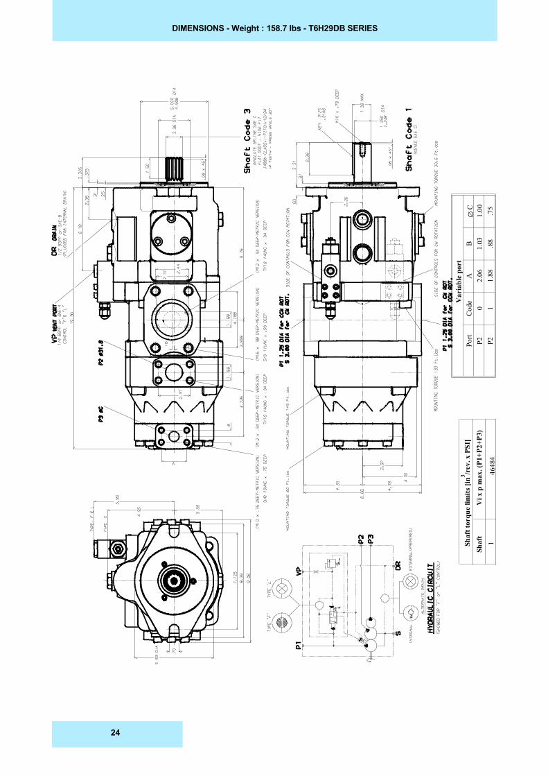
DIMENSIONS - Weight : 158.7 lbs - T6H29DB SERIES
Shaf
t tor
que
limits
[in3 /r
ev. x
PSI
]V
i x p
max
. (P1
+P2+
P3)
Shaf
t
4648
41
Var
iabl
e po
rt
��C
1.00 .75
B 1.03 .88
A 2.06
1.88
Cod
e0 1
Port
P2 P2
24
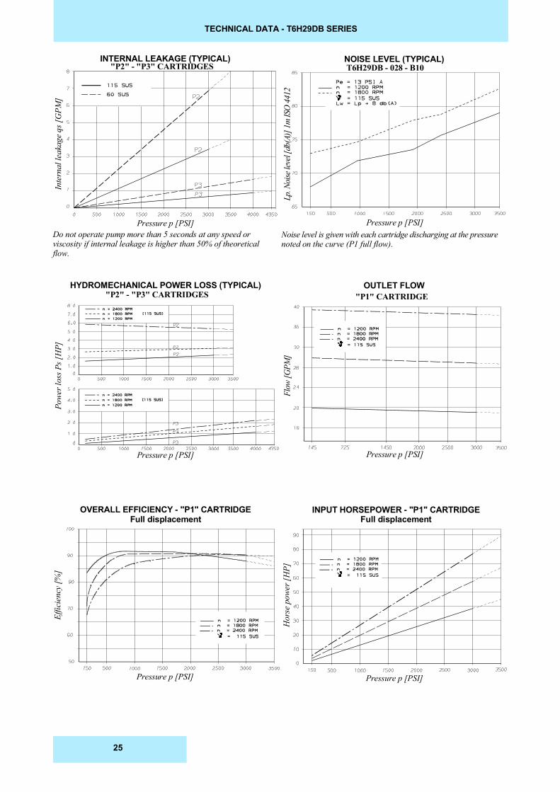
TECHNICAL DATA - T6H29DB SERIES
HYDROMECHANICAL POWER LOSS (TYPICAL)
Effic
ienc
y [%
]
Flow
[GPM
]
Pressure p [PSI]
Pressure p [PSI]Pressure p [PSI]
Lp. N
oise
leve
l [db
(A)]
1m IS
O 44
12
Inte
rnal
leak
age q
s [G
PM]
Pressure p [PSI]Pressure p [PSI]Do not operate pump more than 5 seconds at any speed orviscosity if internal leakage is higher than 50% of theoreticalflow.
OVERALL EFFICIENCY - "P1" CARTRIDGEFull displacement
Hor
se p
ower
[HP]
Pressure p [PSI]
"P1" CARTRIDGE"P2" - "P3" CARTRIDGES
T6H29DB - 028 - B10INTERNAL LEAKAGE (TYPICAL) NOISE LEVEL (TYPICAL)
"P2" - "P3" CARTRIDGES
INPUT HORSEPOWER - "P1" CARTRIDGEFull displacement
OUTLET FLOW
Noise level is given with each cartridge discharging at the pressurenoted on the curve (P1 full flow).
Powe
r los
s Ps [
HP]
25
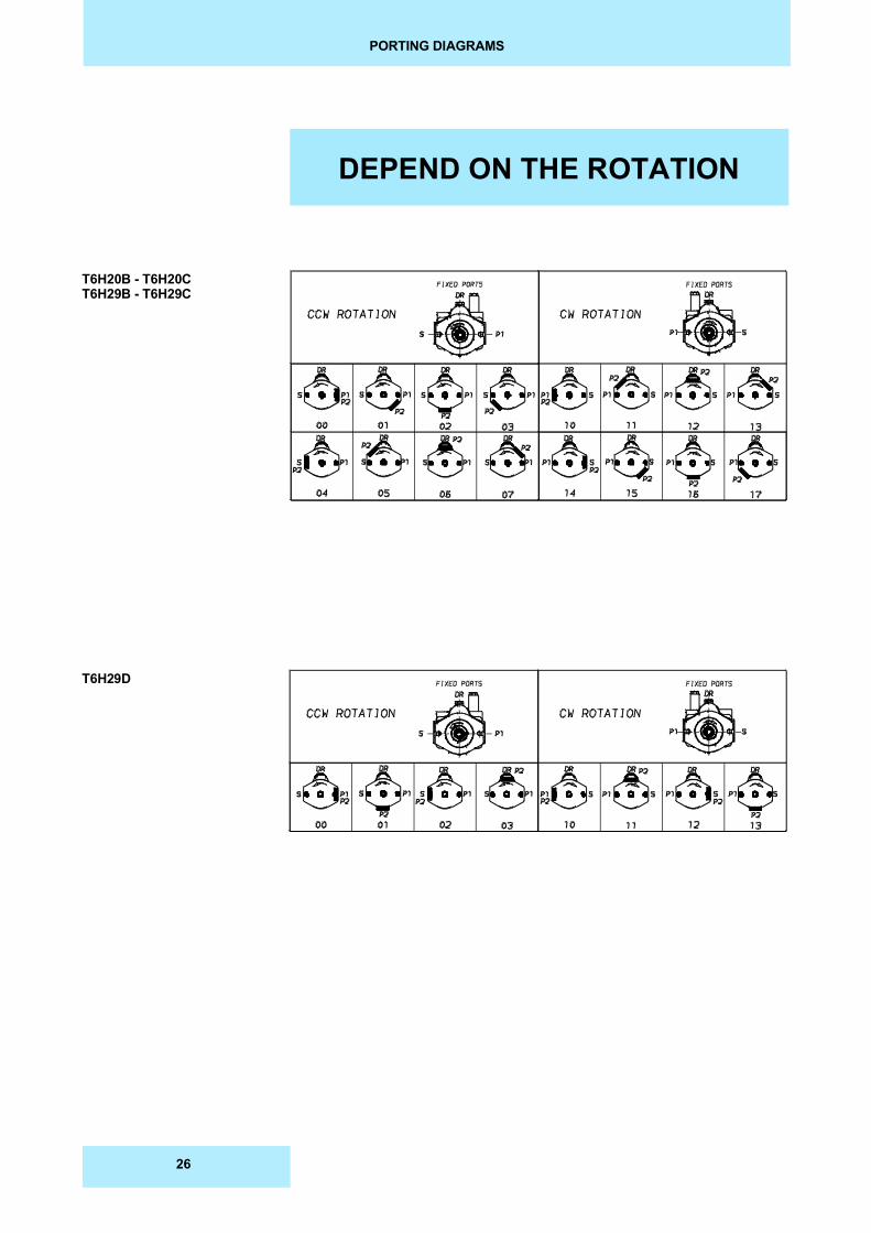
PORTING DIAGRAMS
T6H20B - T6H20CT6H29B - T6H29C
T6H29D
DEPEND ON THE ROTATION
26
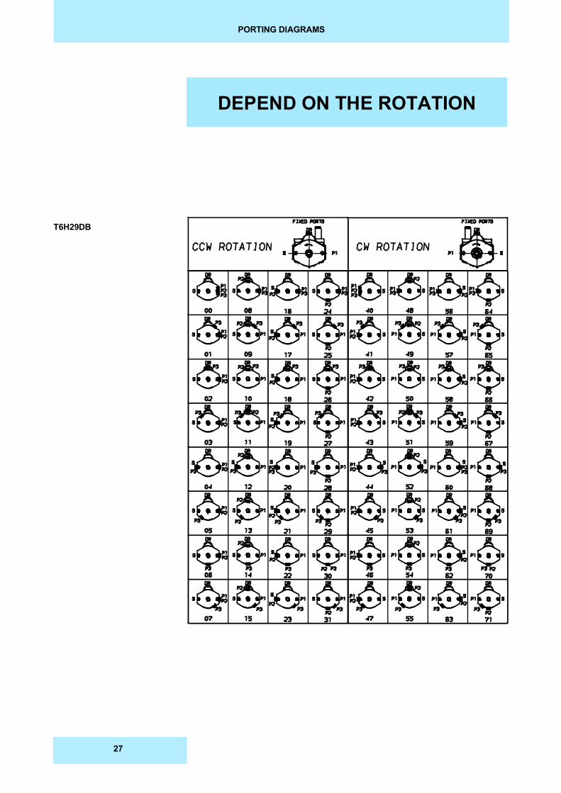
PORTING DIAGRAMS
T6H29DB
DEPEND ON THE ROTATION
27