Embed Size (px)
Citation preview
Appendix E - Manufactured Products
Pennsylvania StormwaterBest Management Practices
ManualDRAFT - JANUARY, 2005

This page intentionally left blank.
PAD
EP B
MP
Man
ual
Sect
ion
Ref
eren
ces
# 1
E &
S
Con
stru
ctio
n P
hase
S
edim
ent
Con
trol
# 2
FGM
Fl
exib
le
grow
th
med
ium
for
reve
geta
tion
# 3
EC
Bs
E
rosi
on
Con
trol
Bla
nket
s
# 4
TRM
s
Turf
R
einf
orce
men
t M
ats
# 5
AC
Bs
A
rticl
uatin
g C
oncr
ete
Blo
cks
# 6
CC
Cel
lula
r C
onfin
emen
t
# 7
WM
PP
W
ire M
esh
Por
ous
pavi
ng
# 8
PP
PS
P
last
ic
Por
ous
Pav
ing
Sys
tem
s
#9 G
CL
G
eosy
n-
th
etic
Cla
y lin
ers
# 10
MP
SS
M
odul
ar
Pla
stic
S
tora
ge
Sys
tem
s
# 11
Geo
s G
eosy
nthe
tic
Rei
nfor
ce-
m
ent
# 12
A
ncho
rs
and
Rod
s
#13
Wat
er Q
ualit
y In
serts
Sect
ion
5.4
BM
Ps: P
reve
ntiv
e
Non
-St
ruct
ural
BM
Ps
1.0
Prot
ect s
ensi
tive
and
spec
ial v
alue
reso
urce
s
BM
P 1
.1 P
rote
ct S
ensi
tive/
Spe
cial
Val
ue F
eatu
res
xx
xx
xx
xx
x
BM
P 1
.2 P
rote
ct/C
onse
rve
Enh
ance
Rip
aria
n A
reas
xx
xx
xx
xx
x
BM
P 1
.3 P
rote
ct/U
tiliz
e N
atur
al F
low
Pat
hway
s in
O
vera
ll S
torm
wat
er P
lann
ing
and
Des
ign
xx
xx
xx
xx
x
2.0
Clu
ster
and
Con
cent
rate
BM
P 2
.1 C
lust
er U
ses
at E
ach
Site
;Bui
ld o
n S
mal
lest
Are
a P
ossi
ble
xx
xx
xx
xx
xx
x
BM
P 2
.2 C
once
ntra
te U
ses
Are
awid
e th
roug
h S
mar
t G
row
th P
ract
ices
xx
x
3.0
Min
imiz
e D
istu
rban
ce a
nd m
inim
ize
Mai
nten
ance
BM
P 3
.1 M
inim
ize
Tota
l Dis
turb
ed A
rea
� G
radi
ngx
xx
xx
xx
xx
xx
x
BM
P 3
.2 M
inim
ize
Soi
l Com
pact
ion
in D
istu
rbed
A
reas
xx
xx
xx
xx
xx
xx
BM
P 3
.3 R
e-V
eget
ate
and
Re-
Fore
st D
istu
rbed
A
reas
, Usi
ng N
ativ
e S
peci
esx
xx
xx
x
4.0
Red
uce
Impe
rvio
us C
over
BM
P 4
.1 R
educ
e S
treet
Impe
rvio
usne
ssx
xx
xx
xx
xB
MP
4.2
Red
uce
park
ing
Impe
rvio
usne
ssx
xx
xx
xx
x
5.0
Dis
conn
ect -
Dis
trib
ute
- Dec
entr
aliz
e
BM
P 5
.1 R
oofto
p D
isco
nnec
tion
x
xx
xx
x
BM
P 5
.2 D
isco
nnec
tion
from
Sto
rm S
ewer
sx
xx
xx
xx
xx
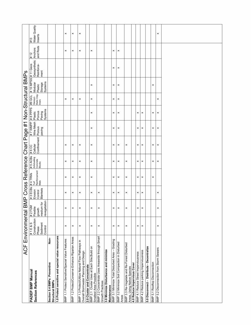
AC
F E
nviro
nmen
tal B
MP
Cro
ss R
efer
ence
Cha
rt P
age
#1 N
on-S
truct
ural
BM
Ps
PAD
EP B
MP
Man
ual
Sect
ion
Ref
eren
ces
# 1
E &
S
Con
stru
ctio
n P
hase
S
edim
ent
Con
trol
# 2
FGM
Fl
exib
le
grow
th
med
ium
for
reve
geta
tion
# 3
EC
Bs
E
rosi
on
Con
trol
Bla
nket
s
# 4
TRM
s
Turf
R
einf
orce
men
t M
ats
# 5
AC
Bs
A
rticl
uatin
g C
oncr
ete
Blo
cks
# 6
CC
Cel
lula
r C
onfin
emen
t
# 7
WM
PP
W
ire M
esh
Por
ous
pavi
ng
# 8
PP
PS
P
last
ic
Por
ous
Pav
ing
Sys
tem
s
#9 G
CL
G
eosy
n-
th
etic
Cla
y lin
ers
# 10
MP
SS
M
odul
ar
Pla
stic
S
tora
ge
Sys
tem
s
# 11
Geo
s G
eosy
nthe
tic
Rei
nfor
ce-
m
ent
# 12
A
ncho
rs
and
Rod
s
#13
Wat
er Q
ualit
y In
serts
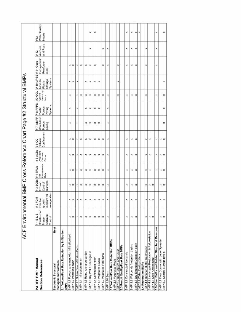
Sect
ion
6: S
truc
tura
l
B
est
man
agem
ent P
ract
ices
6.1
Volu
me/
Peak
Rat
e R
educ
tion
by In
filtr
atio
n B
MPs
BM
P 1
.1 P
orou
s pa
vem
ent w
ith in
filtra
tion
bed
xx
xx
xx
xx
xx
xB
MP
1.2
Infil
tratio
n ba
sin
xx
xx
xx
xx
BM
P 1
.3 S
ubsu
rface
Infil
tratio
n B
eds
xx
xx
xx
xx
xx
xB
MP
1.4
Inf
iltra
tion
trenc
hx
xx
xx
xx
x
BM
P 1
.5 R
ain
/ rec
harg
e ga
rden
xx
xx
xx
xx
xx
xB
MP
1.6
Dry
Wel
l / S
eepa
ge P
itx
xx
xx
xx
xx
xx
xx
BM
P 1
.7 C
onst
ruct
ed F
ilter
xx
xx
xx
xx
xx
xx
BM
P 1
.8 V
eget
ated
Sw
ale
xx
xx
xx
xx
xx
BM
P 1
.9 V
eget
ated
Filt
er S
trip
xx
xx
xx
xx
xB
MP
1.1
0 B
erm
xx
xx
xx
xx
xx
x6.
2 Vo
lum
e/Pe
ak R
ate
Red
uctio
n B
MPs
BM
P 2
.1 V
eget
ated
Roo
fsB
MP
2.2
Roo
f Cap
ture
and
Reu
sex
xx
x6.
3 R
unof
f Qua
lity/
Peak
Rat
e B
MPs
BM
P 3
.1 C
onst
ruct
ed W
etla
nds
xx
xx
xx
xx
xx
BM
P 3
.2 W
et p
onds
/ re
tent
ion
basi
nsx
xx
xx
xx
xx
xB
MP
3.3
Dry
Ext
ende
d D
eten
tion
basi
nx
xx
xx
xx
xx
xB
MP
3.4
Wat
er Q
ualit
y Fi
lters
x6.
4 R
esto
ratio
n B
MPs
BM
P 4
.1 R
ipar
ian
Buf
fer R
esto
ratio
nx
xx
xx
xx
xx
BM
P 4
.2 L
ands
cape
Res
tora
tion
& R
efor
esta
tion
xx
xx
xx
BM
P 4
.3 S
oils
Am
endm
ent
xx
x6.
5 O
ther
BM
Ps a
nd R
elat
ed S
truc
tura
l Mea
sure
sx
xx
xx
xx
BM
P 5
.1 F
low
Con
trol w
ith L
evel
Spr
eade
rx
xx
xx
xB
MP
5.2
Spe
cial
Sto
rage
BM
Ps
xx
xx
xx
xx
xx
x
AC
F E
nviro
nmen
tal B
MP
Cro
ss R
efer
ence
Cha
rt P
age
#2 S
truct
ural
BM
Ps
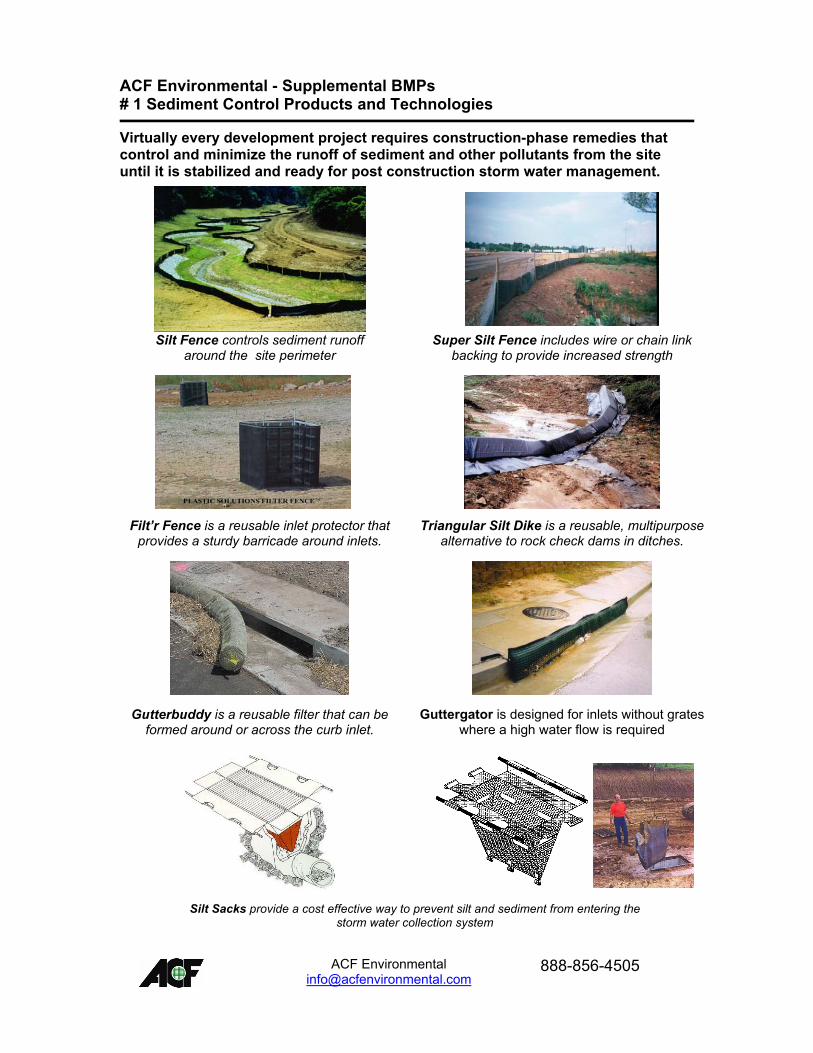
ACF Environmental - Supplemental BMPs # 1 Sediment Control Products and Technologies
Virtually every development project requires construction-phase remedies that control and minimize the runoff of sediment and other pollutants from the site until it is stabilized and ready for post construction storm water management.
Silt Fence controls sediment runoff
around the site perimeter Super Silt Fence includes wire or chain link
backing to provide increased strength
Filt�r Fence is a reusable inlet protector that provides a sturdy barricade around inlets.
Triangular Silt Dike is a reusable, multipurpose alternative to rock check dams in ditches.
Gutterbuddy is a reusable filter that can be formed around or across the curb inlet.
Guttergator is designed for inlets without grates where a high water flow is required
Silt Sacks provide a cost effective way to prevent silt and sediment from entering the
storm water collection system
ACF Environmental
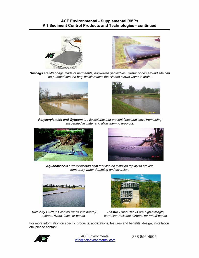
ACF Environmental - Supplemental BMPs # 1 Sediment Control Products and Technologies - continued
Dirtbags are filter bags made of permeable, nonwoven geotextiles. Water ponds around site can be pumped into the bag, which retains the silt and allows water to drain.
Polyacrylamide and Gypsum are flocculants that prevent fines and clays from being suspended in water and allow them to drop out.
Aquabarrier is a water inflated dam that can be installed rapidly to provide temporary water damming and diversion.
Turbidity Curtains control runoff into nearby oceans, rivers, lakes or ponds.
Plastic Trash Racks are high-strength, corrosion-resistant screens for runoff ponds.
For more information on specific products, applications, features and benefits, design, installation etc, please contact:
ACF Environmental
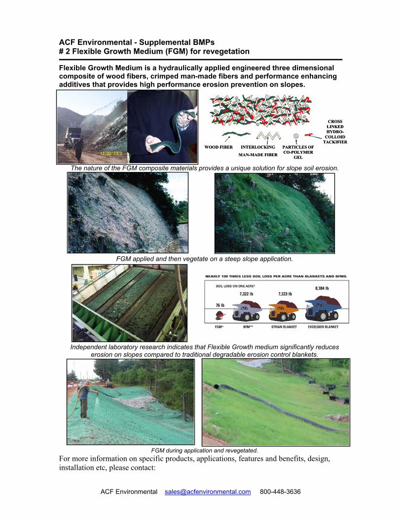
ACF Environmental - Supplemental BMPs # 2 Flexible Growth Medium (FGM) for revegetation
Flexible Growth Medium is a hydraulically applied engineered three dimensional composite of wood fibers, crimped man-made fibers and performance enhancing additives that provides high performance erosion prevention on slopes.
The nature of the FGM composite materials provides a unique solution for slope soil erosion.
FGM applied and then vegetate on a steep slope application.
Independent laboratory research indicates that Flexible Growth medium significantly reduces erosion on slopes compared to traditional degradable erosion control blankets.
FGM during application and revegetated.
WOOD FIBER PARTICLES OF CO-POLYMER
GEL
CROSS LINKED HYDRO-
COLLOID TACKIFIER
INTERLOCKING
MAN-MADE FIBER
WOOD FIBER PARTICLES OF CO-POLYMER
GEL
CROSS LINKED HYDRO-
COLLOID TACKIFIER
INTERLOCKING
MAN-MADE FIBER
For more information on specific products, applications, features and benefits, design, installation etc, please contact:
ACF Environmental [email protected] 800-448-3636
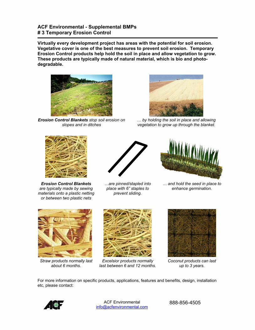
ACF Environmental - Supplemental BMPs # 3 Temporary Erosion Control
Virtually every development project has areas with the potential for soil erosion. Vegetative cover is one of the best measures to prevent soil erosion. Temporary Erosion Control products help hold the soil in place and allow vegetation to grow. These products are typically made of natural material, which is bio and photo-degradable.
Erosion Control Blankets stop soil erosion on
slopes and in ditches
� by holding the soil in place and allowing vegetation to grow up through the blanket.
Erosion Control Blankets are typically made by sewing
materials onto a plastic netting or between two plastic nets
�are pinned/stapled into place with 6� staples to
prevent sliding.
� and hold the seed in place to enhance germination.
Straw products normally last
about 6 months. Excelsior products normally
last between 6 and 12 months.Coconut products can last
up to 3 years.
For more information on specific products, applications, features and benefits, design, installation etc, please contact:
ACF Environmental
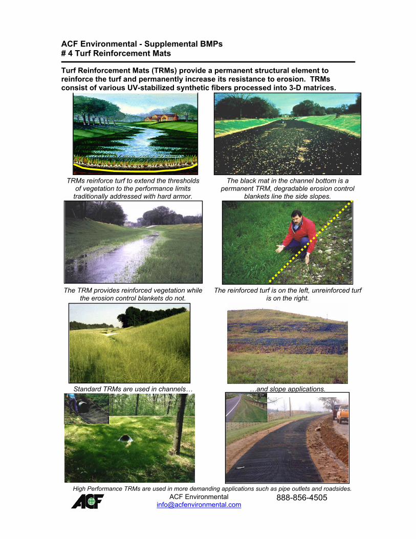
ACF Environmental - Supplemental BMPs # 4 Turf Reinforcement Mats
Turf Reinforcement Mats (TRMs) provide a permanent structural element to reinforce the turf and permanently increase its resistance to erosion. TRMs consist of various UV-stabilized synthetic fibers processed into 3-D matrices.
TRMs reinforce turf to extend the thresholds
of vegetation to the performance limits traditionally addressed with hard armor.
The black mat in the channel bottom is a permanent TRM, degradable erosion control
blankets line the side slopes.
The TRM provides reinforced vegetation while the erosion control blankets do not.
The reinforced turf is on the left, unreinforced turf is on the right.
Standard TRMs are used in channels� �and slope applications.
High Performance TRMs are used in more demanding applications such as pipe outlets and roadsides.
Landlok TRMs intro slideLandlok TRMs intro slide
pipe outlet afterpipe outlet after
ACF Environmental
ACF Environmental - Supplemental BMPs # 4 Turf Reinforcement Mats - continued
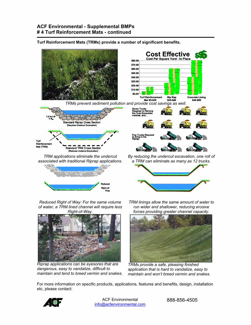
Turf Reinforcement Mats (TRMs) provide a number of significant benefits.
TRMs prevent sediment pollution and provide cost savings as well.
TRM applications eliminate the undercut associated with traditional Riprap applications.
By reducing the undercut excavation, one roll of a TRM can eliminate as many as 12 trucks.
Reduced Right of Way: For the same volume of water, a TRM lined channel will require less
Right-of-Way.
TRM linings allow the same amount of water to run wider and shallower, reducing erosive forces providing greater channel capacity.
Riprap applications can be eyesores that are dangerous, easy to vandalize, difficult to maintain and tend to breed vermin and snakes.
TRMs provide a safe, pleasing finished application that is hard to vandalize, easy to maintain and won�t breed vermin and snakes.
Cost EffectiveCost EffectiveCost Per Square Yard - In Place
$0.00
$10.00$20.00
$30.00$40.00
$50.00
$60.00$70.00
$80.00
Turf ReinforcementMat $5-$20
Rip Rap$25-$60
Concrete Lining $40-$80
Cost EffectiveCost EffectiveCost Per Square Yard - In Place
$0.00
$10.00$20.00
$30.00$40.00
$50.00
$60.00$70.00
$80.00
Turf ReinforcementMat $5-$20
Rip Rap$25-$60
Concrete Lining $40-$80
1.5 to 2.0x d50
Standard Riprap Cross Section(Requires Undercut Excavation)
Turf Reinforcement Mat (TRM) Standard TRM Cross Section
(Reduces Undercut Excavation)
1.5 to 2.0x d50
Standard Riprap Cross Section(Requires Undercut Excavation)
1.5 to 2.0x d50
Standard Riprap Cross Section(Requires Undercut Excavation)
Turf Reinforcement Mat (TRM) Standard TRM Cross Section
(Reduces Undercut Excavation)
Turf Reinforcement Mat (TRM) Standard TRM Cross Section
(Reduces Undercut Excavation)
Five Trucks Required to Bring in the Riprap.
Seven Trucks Required to Remove the Over-Excavated material, and...
Five Trucks Required to Bring in the Riprap.
Five Trucks Required to Bring in the Riprap.
Seven Trucks Required to Remove the Over-Excavated material, and...
Seven Trucks Required to Remove the Over-Excavated material, and...
Reduced
Right-of-Way
Reduced
Right-of-Way
Reduced
Right-of-Way
For more information on specific products, applications, features and benefits, design, installation etc, please contact:
ACF Environmental
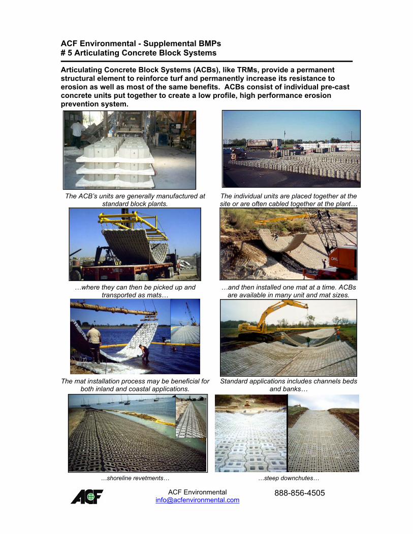
ACF Environmental - Supplemental BMPs # 5 Articulating Concrete Block Systems
Articulating Concrete Block Systems (ACBs), like TRMs, provide a permanent structural element to reinforce turf and permanently increase its resistance to erosion as well as most of the same benefits. ACBs consist of individual pre-cast concrete units put together to create a low profile, high performance erosion prevention system.
The ACB�s units are generally manufactured at
standard block plants. The individual units are placed together at the site or are often cabled together at the plant�
�where they can then be picked up and
transported as mats� �and then installed one mat at a time. ACBs
are available in many unit and mat sizes.
The mat installation process may be beneficial for
both inland and coastal applications. Standard applications includes channels beds
and banks�
�shoreline revetments� �steep downchutes�
ACF Environmental
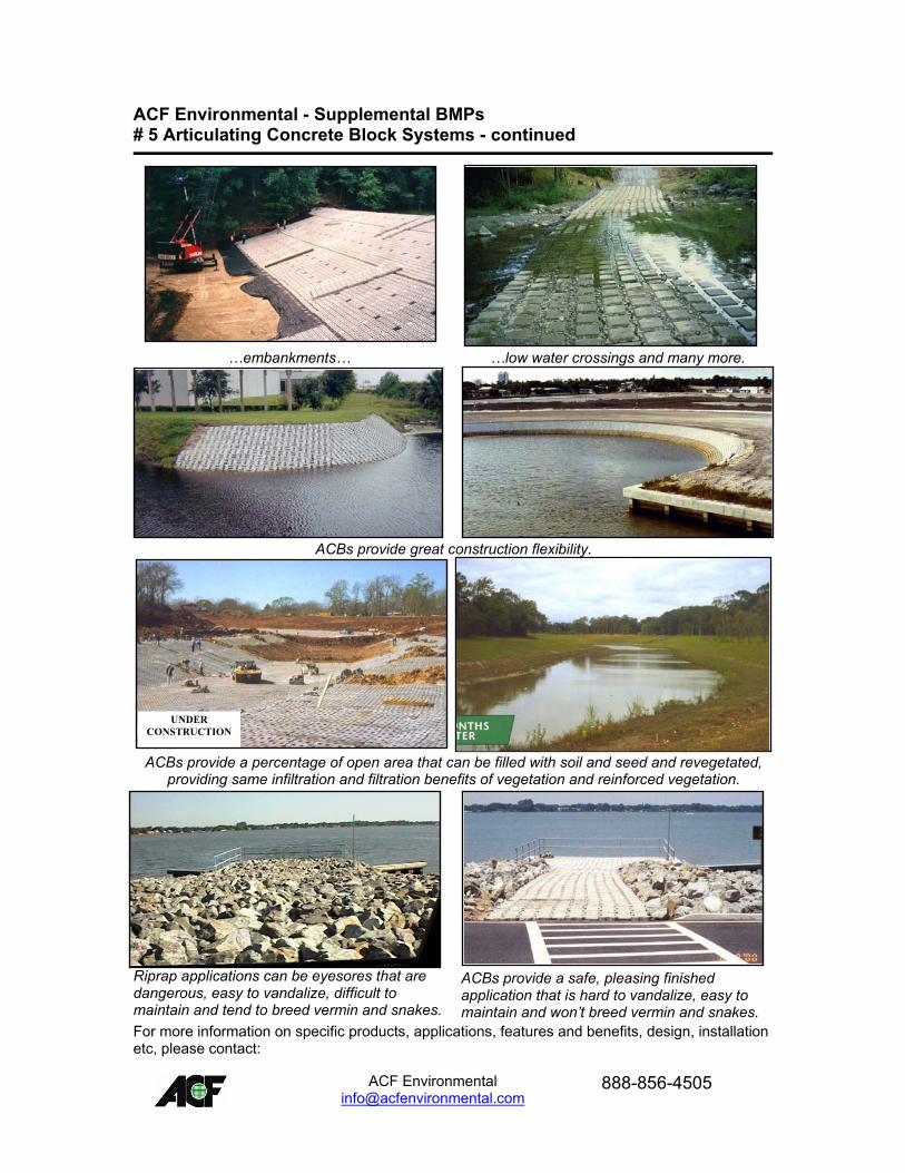
ACF Environmental - Supplemental BMPs # 5 Articulating Concrete Block Systems - continued
�embankments� �low water crossings and many more.
ACBs provide great construction flexibility.
ACBs provide a percentage of open area that can be filled with soil and seed and revegetated, providing same infiltration and filtration benefits of vegetation and reinforced vegetation.
Riprap applications can be eyesores that are dangerous, easy to vandalize, difficult to maintain and tend to breed vermin and snakes.
ACBs provide a safe, pleasing finished application that is hard to vandalize, easy to maintain and won�t breed vermin and snakes.
6 MONTHSLATER
6 MONTHSLATER
UNDERCONSTRUCTION
UNDERCONSTRUCTION
For more information on specific products, applications, features and benefits, design, installation etc, please contact:
ACF Environmental
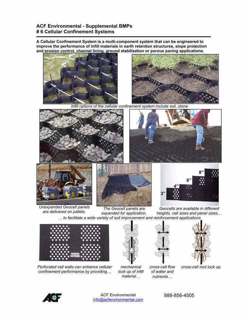
ACF Environmental - Supplemental BMPs # 6 Cellular Confinement Systems
A Cellular Confinement System is a multi-component system that can be engineered to improve the performance of infill materials in earth retention structures, slope protection and erosion control, channel lining, ground stabilization or porous paving applications.
Infill options of the cellular confinement system include soil, stone
Unexpanded Geocell panels
are delivered on pallets.
The Geocell panels are
expanded for application.
8�
3�4�
6�
8�
3�4�
6�
Geocells are available in different
heights, cell sizes and panel sizes� � to facilitate a wide variety of soil improvement and reinforcement applications
Perforated cell walls can enhance cellular confinement performance by providing�
mechanical lock up of infill
material�
cross-cell flow of water and nutrients�
cross-cell root lock up.
ACF Environmental
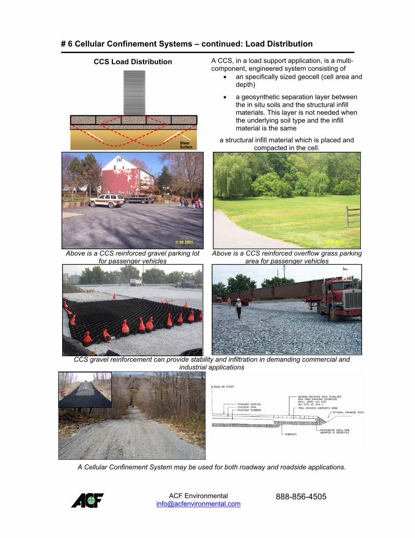
# 6 Cellular Confinement Systems � continued: Load Distribution
A CCS, in a load support application, is a multi-component, engineered system consisting of
• an specifically sized geocell (cell area and depth)
• a geosynthetic separation layer between the in situ soils and the structural infill materials. This layer is not needed when the underlying soil type and the infill material is the same
a structural infill material which is placed and compacted in the cell.
Above is a CCS reinforced gravel parking lot
for passenger vehicles Above is a CCS reinforced overflow grass parking
area for passenger vehicles
CCS gravel reinforcement can provide stability and infiltration in demanding commercial and
industrial applications
A Cellular Confinement System may be used for both roadway and roadside applications.
CCS Load Distribution
ShearSurface
CCS Load Distribution
ShearSurfaceShearSurface
ACF Environmental
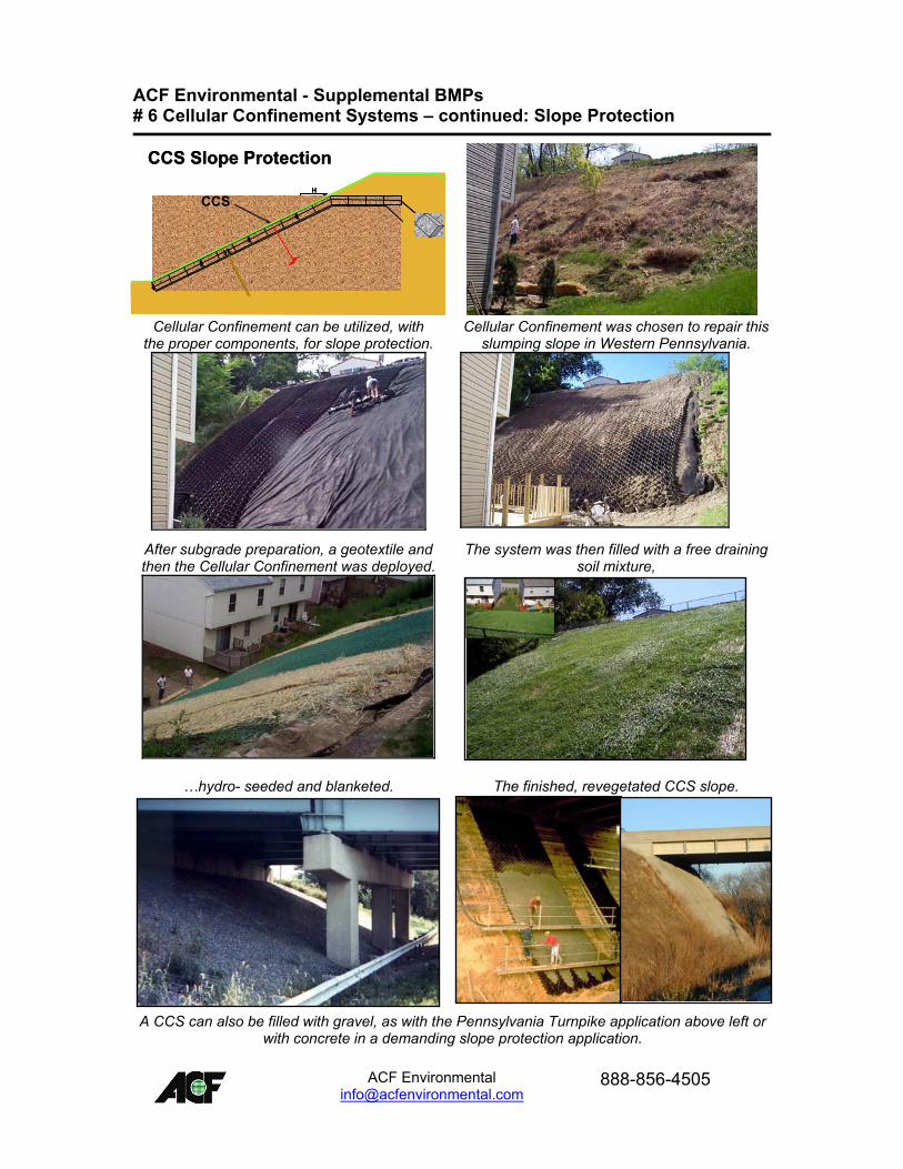
ACF Environmental - Supplemental BMPs # 6 Cellular Confinement Systems � continued: Slope Protection
Cellular Confinement can be utilized, with the proper components, for slope protection.
Cellular Confinement was chosen to repair this slumping slope in Western Pennsylvania.
After subgrade preparation, a geotextile and then the Cellular Confinement was deployed.
The system was then filled with a free draining soil mixture,
�hydro- seeded and blanketed. The finished, revegetated CCS slope.
A CCS can also be filled with gravel, as with the Pennsylvania Turnpike application above left or with concrete in a demanding slope protection application.
CCS Slope Protection
VH
CCS
CCS Slope Protection
VH
CCS
ACF Environmental
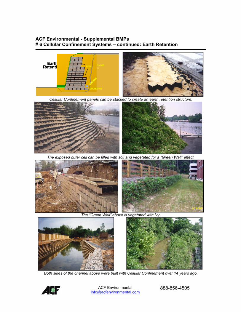
ACF Environmental - Supplemental BMPs # 6 Cellular Confinement Systems � continued: Earth Retention
Cellular Confinement panels can be stacked to create an earth retention structure.
The exposed outer cell can be filled with soil and vegetated for a �Green Wall� effect.
The �Green Wall� above is vegetated with ivy.
Both sides of the channel above were built with Cellular Confinement over 14 years ago.
Earth
Retention RETAINEDSOIL
INFILL
GEOTEXTILE
SUBDRAIN
Earth Retention RETAINED
SOILINFILL
GEOTEXTILEGEOTEXTILE
SUBDRAIN
SUBDRAIN
ACF Environmental
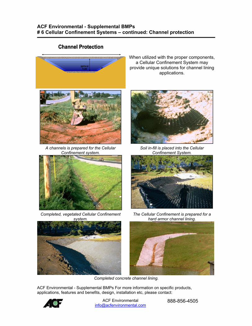
ACF Environmental - Supplemental BMPs # 6 Cellular Confinement Systems � continued: Channel protection
When utilized with the proper components, a Cellular Confinement System may
provide unique solutions for channel lining applications.
A channels is prepared for the Cellular
Confinement system. Soil in-fill is placed into the Cellular
Confinement System.
Completed, vegetated Cellular Confinement
system. The Cellular Confinement is prepared for a
hard armor channel lining.
Completed concrete channel lining.
Channel ProtectionTOP WIDTH
HV
DEPTH OFFLOW
Channel ProtectionTOP WIDTH
HV
HV
DEPTH OFFLOW
DEPTH OFFLOW
ACF Environmental - Supplemental BMPs For more information on specific products, applications, features and benefits, design, installation etc, please contact:
ACF Environmental
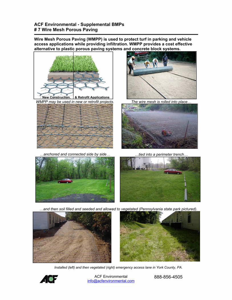
ACF Environmental - Supplemental BMPs # 7 Wire Mesh Porous Paving
Wire Mesh Porous Paving (WMPP) is used to protect turf in parking and vehicle access applications while providing infiltration. WMPP provides a cost effective alternative to plastic porous paving systems and concrete block systems.
WMPP may be used in new or retrofit projects. The wire mesh is rolled into place�
�anchored and connected side by side� �tied into a perimeter trench�
�and then soil filled and seeded and allowed to vegetated (Pennsylvania state park pictured).
Installed (left) and then vegetated (right) emergency access lane in York County, PA.
New Construction, & Retrofit ApplicationsNew Construction, & Retrofit Applications
ACF Environmental
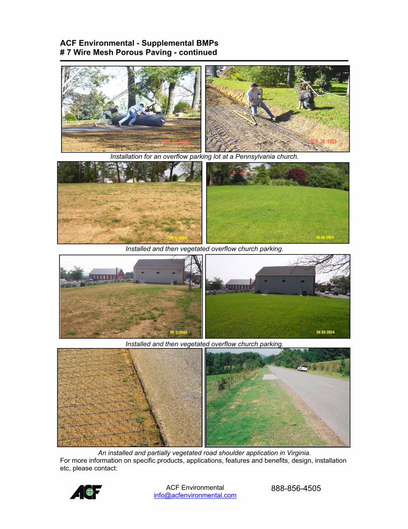
ACF Environmental - Supplemental BMPs # 7 Wire Mesh Porous Paving - continued
Installation for an overflow parking lot at a Pennsylvania church.
Installed and then vegetated overflow church parking.
Installed and then vegetated overflow church parking.
An installed and partially vegetated road shoulder application in Virginia.
For more information on specific products, applications, features and benefits, design, installation etc, please contact:
ACF Environmental
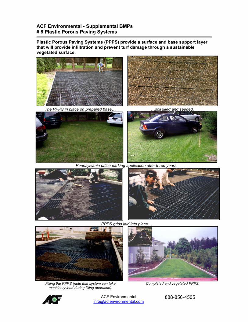
ACF Environmental - Supplemental BMPs # 8 Plastic Porous Paving Systems
Plastic Porous Paving Systems (PPPS) provide a surface and base support layer that will provide infiltration and prevent turf damage through a sustainable vegetated surface.
The PPPS in place on prepared base� �soil filled and seeded.
Pennsylvania office parking application after three years.
PPPS grids laid into place�
Filling the PPPS (note that system can take machinery load during filling operation).
Completed and vegetated PPPS.
ACF Environmental
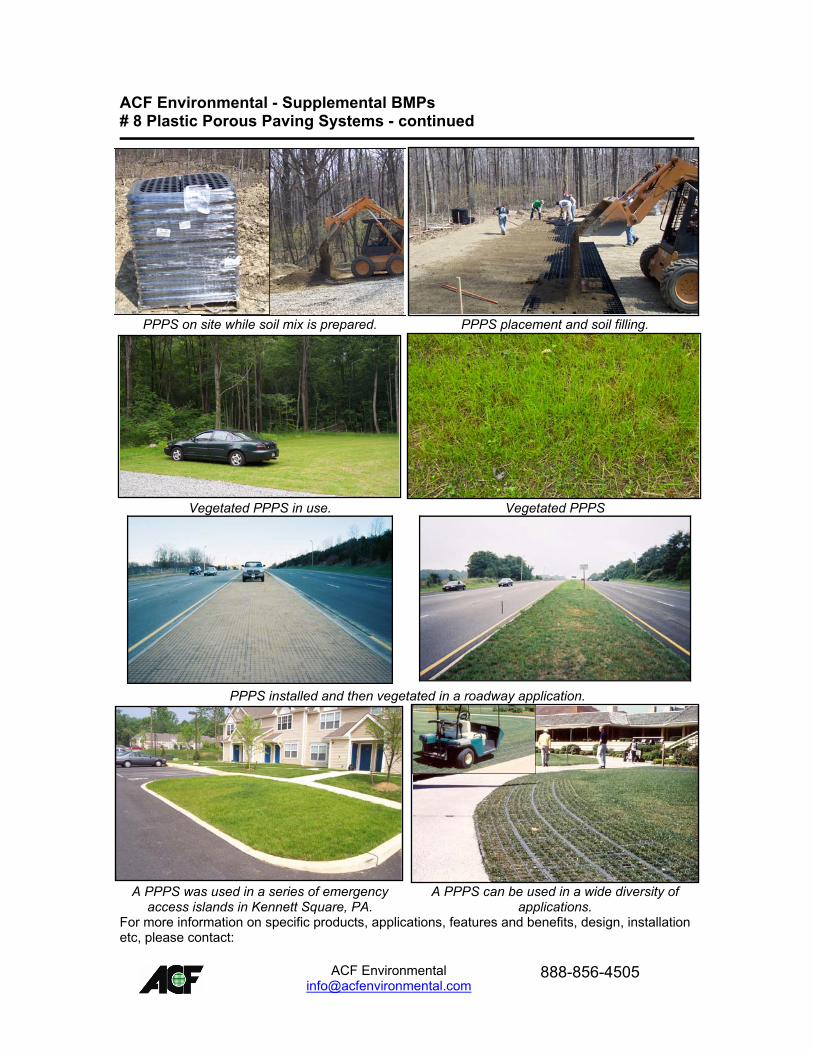
ACF Environmental - Supplemental BMPs # 8 Plastic Porous Paving Systems - continued
PPPS on site while soil mix is prepared. PPPS placement and soil filling.
Vegetated PPPS in use. Vegetated PPPS
PPPS installed and then vegetated in a roadway application.
A PPPS was used in a series of emergency access islands in Kennett Square, PA.
A PPPS can be used in a wide diversity of applications.
For more information on specific products, applications, features and benefits, design, installation etc, please contact:
ACF Environmental
ACF Environmental - Supplemental BMPs # 9 Geosynthetic Clay Liner (GCL)
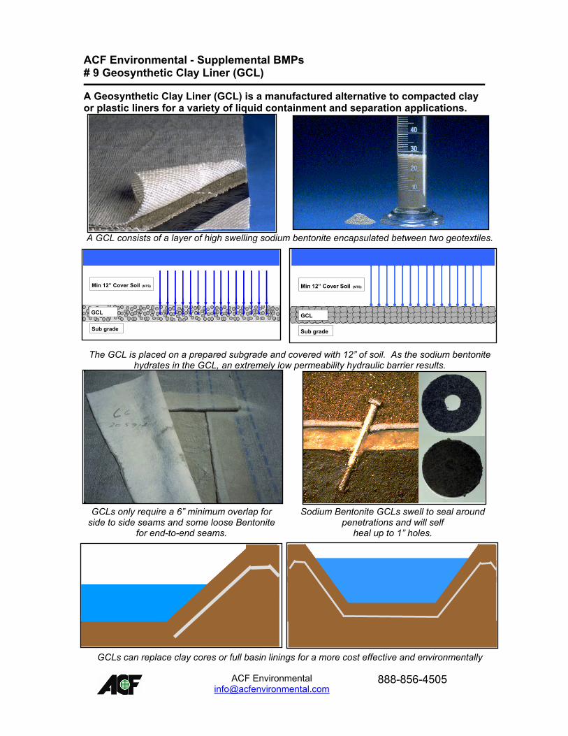
A Geosynthetic Clay Liner (GCL) is a manufactured alternative to compacted clay or plastic liners for a variety of liquid containment and separation applications.
A GCL consists of a layer of high swelling sodium bentonite encapsulated between two geotextiles.
The GCL is placed on a prepared subgrade and covered with 12� of soil. As the sodium bentonite hydrates in the GCL, an extremely low permeability hydraulic barrier results.
GCLs only require a 6� minimum overlap for side to side seams and some loose Bentonite
for end-to-end seams.
Sodium Bentonite GCLs swell to seal around penetrations and will self
heal up to 1� holes.
GCLs can replace clay cores or full basin linings for a more cost effective and environmentally
Sub grade
Min 12� Cover Soil (NTS)
GCL
Sub grade
Min 12� Cover Soil (NTS)
GCL
Sub grade
GCL
Min 12� Cover Soil (NTS)
Sub grade
GCLGCL
Min 12� Cover Soil (NTS)Min 12� Cover Soil (NTS)
ACF Environmental
friendly application. ACF Environmental - Supplemental BMPs # 9 Geosynthetic Clay Liner (GCL) - continued
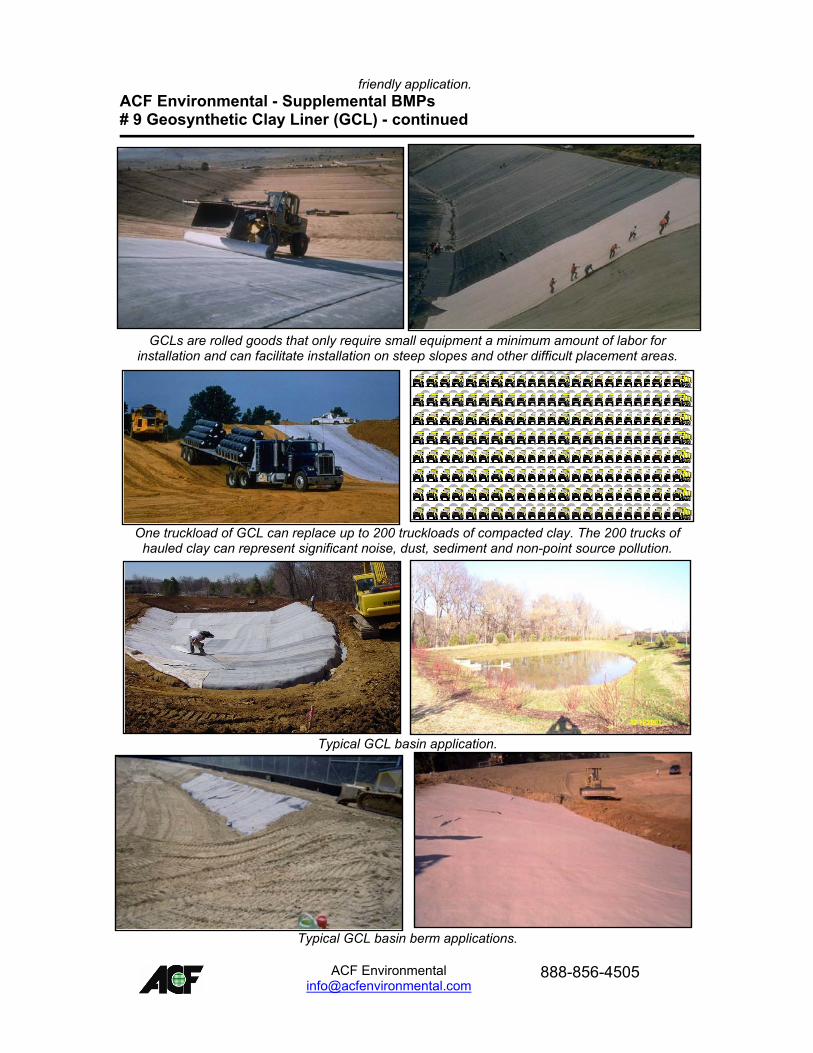
GCLs are rolled goods that only require small equipment a minimum amount of labor for installation and can facilitate installation on steep slopes and other difficult placement areas.
One truckload of GCL can replace up to 200 truckloads of compacted clay. The 200 trucks of hauled clay can represent significant noise, dust, sediment and non-point source pollution.
Typical GCL basin application.
Typical GCL basin berm applications.
ACF Environmental

ACF Environmental
For more information on specific products, applications, features and benefits, design, installation etc, please contact:
ACF Environmental - Supplemental BMPs # 10 Modular Plastic Storage Systems (MPSS)
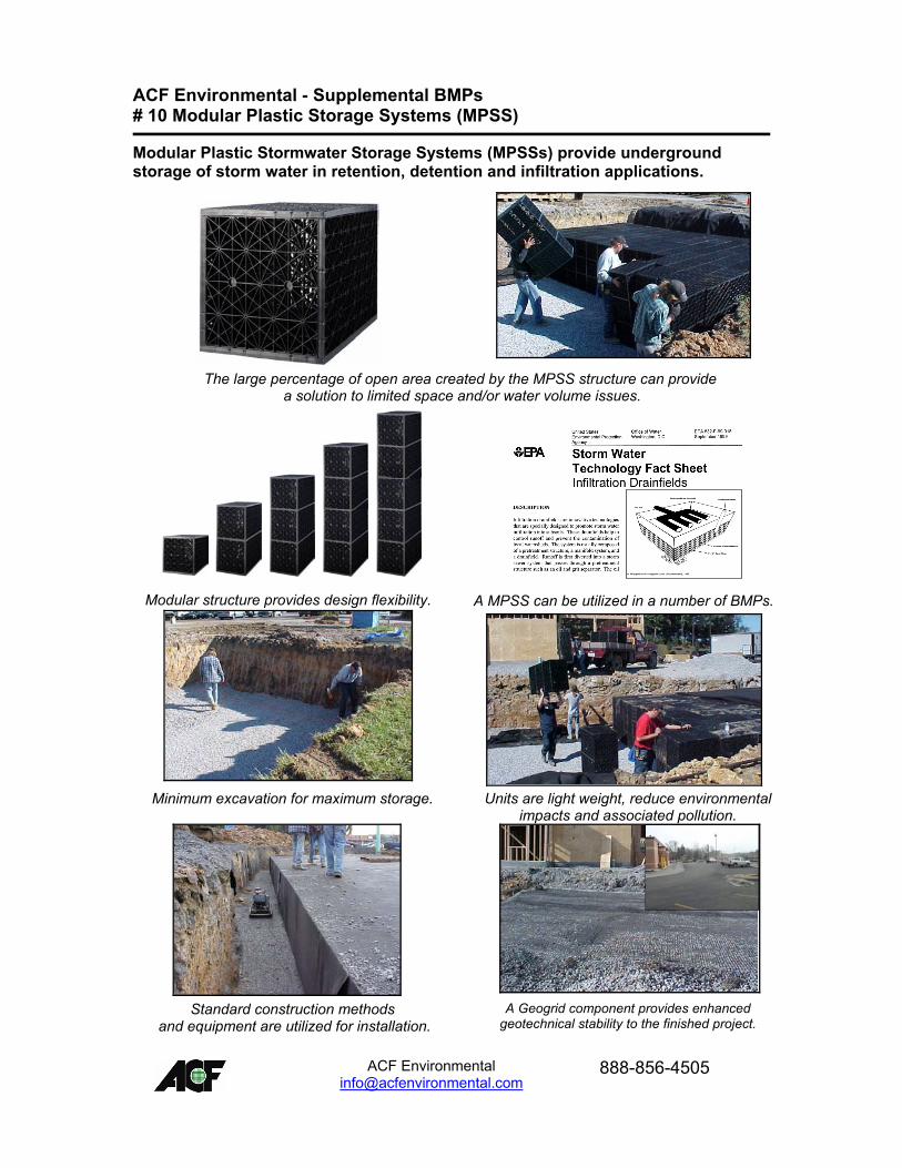
Modular Plastic Stormwater Storage Systems (MPSSs) provide underground storage of storm water in retention, detention and infiltration applications.
The large percentage of open area created by the MPSS structure can provide
a solution to limited space and/or water volume issues.
Modular structure provides design flexibility. A MPSS can be utilized in a number of BMPs.
Minimum excavation for maximum storage. Units are light weight, reduce environmental
impacts and associated pollution.
Standard construction methods
and equipment are utilized for installation. A Geogrid component provides enhanced
geotechnical stability to the finished project.
ACF Environmental
ACF Environmental - Supplemental BMPs # 10 Modular Plastic Storage Systems (MPSS) - continued
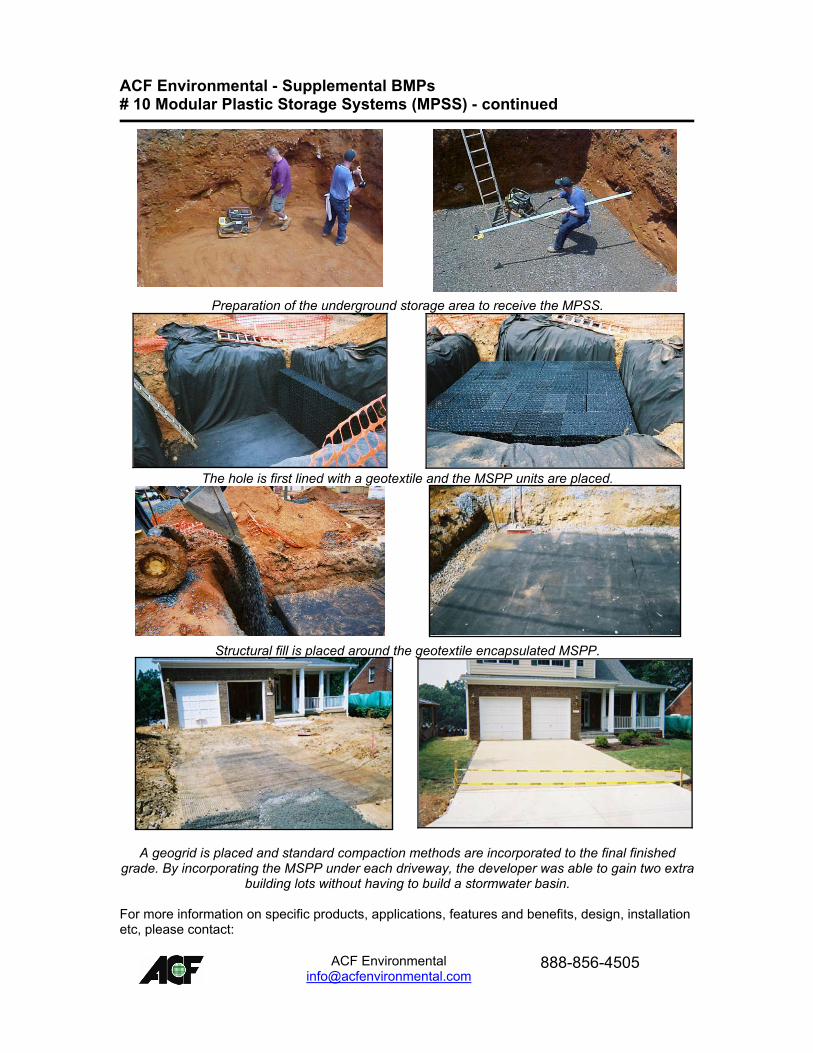
Preparation of the underground storage area to receive the MPSS.
The hole is first lined with a geotextile and the MSPP units are placed.
Structural fill is placed around the geotextile encapsulated MSPP.
A geogrid is placed and standard compaction methods are incorporated to the final finished grade. By incorporating the MSPP under each driveway, the developer was able to gain two extra
building lots without having to build a stormwater basin. For more information on specific products, applications, features and benefits, design, installation etc, please contact:
ACF Environmental
ACF Environmental - Supplemental BMPs # 11 Geosynthetic Base Reinforcement
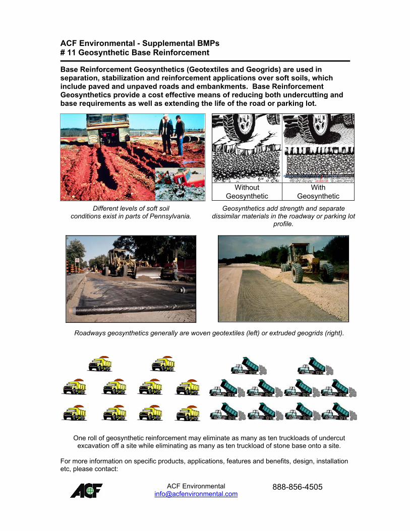
Base Reinforcement Geosynthetics (Geotextiles and Geogrids) are used in separation, stabilization and reinforcement applications over soft soils, which include paved and unpaved roads and embankments. Base Reinforcement Geosynthetics provide a cost effective means of reducing both undercutting and base requirements as well as extending the life of the road or parking lot.
Without Geosynthetic
With Geosynthetic
Without Geosynthetic
With Geosynthetic
Different levels of soft soil conditions exist in parts of Pennsylvania.
Geosynthetics add strength and separate dissimilar materials in the roadway or parking lot
profile.
Roadways geosynthetics generally are woven geotextiles (left) or extruded geogrids (right).
One roll of geosynthetic reinforcement may eliminate as many as ten truckloads of undercut excavation off a site while eliminating as many as ten truckload of stone base onto a site.
For more information on specific products, applications, features and benefits, design, installation etc, please contact:
ACF Environmental
ACF Environmental - Supplemental BMPs # 12 Earth Anchors and Rods
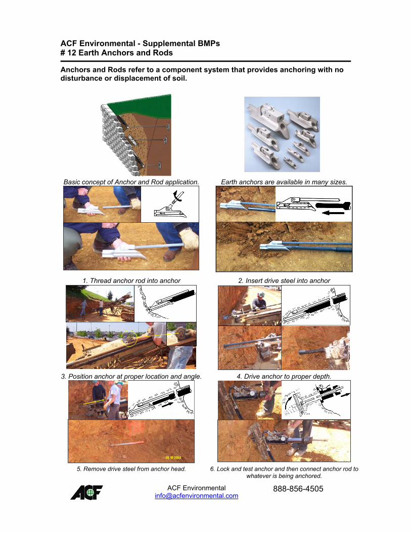
Anchors and Rods refer to a component system that provides anchoring with no disturbance or displacement of soil.
Basic concept of Anchor and Rod application. Earth anchors are available in many sizes.
1. Thread anchor rod into anchor 2. Insert drive steel into anchor
3. Position anchor at proper location and angle. 4. Drive anchor to proper depth.
5. Remove drive steel from anchor head. 6. Lock and test anchor and then connect anchor rod to
whatever is being anchored.
ACF Environmental
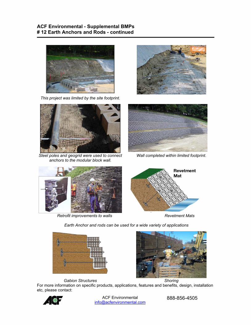
ACF Environmental - Supplemental BMPs # 12 Earth Anchors and Rods - continued
This project was limited by the site footprint.
Steel poles and geogrid were used to connect anchors to the modular block wall.
Wall completed within limited footprint.
Retrofit improvements to walls Revetment Mats
Earth Anchor and rods can be used for a wide variety of applications
Gabion Structures Shoring
For more information on specific products, applications, features and benefits, design, installation etc, please contact:
ACF Environmental
ACF Environmental - Supplemental BMPs # 13 Water Quality Inserts
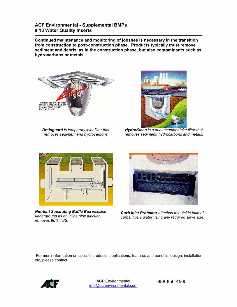
Continued maintenance and monitoring of jobsites is necessary in the transition from construction to post-construction phase. Products typically must remove sediment and debris, as in the construction phase, but also contaminants such as hydrocarbons or metals.
Drainguard is temporary inlet filter that removes sediment and hydrocarbons
HydroKleen is a dual-chamber inlet filter that removes sediment, hydrocarbons and metals.
Nutrient Separating Baffle Box installed underground as an inline pipe junction, removes 90% TSS.
Curb Inlet Protector attaches to outside face of curbs, filters water using any required sieve size.
For more information on specific products, applications, features and benefits, design, installation etc, please contact:
ACF Environmental
Structural BMP Criteria BMP #: Manufactured Treatment Device (MTD) TERRE KLEEN� B IO T AG R E E N R O O F SP A V E R SS T R E E T S W E E P E R S
F ILT E R SIN F ILT R A T IO ND E T E N T IO NR IV E RL A K E
M AN U F AC T U R E D T R E A T M E N T D E V IC E O C E A N
IN L E T S
G E N E R IC
IN S E R T
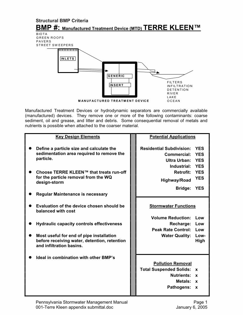
Manufactured Treatment Devices or hydrodynamic separators are commercially available (manufactured) devices. They remove one or more of the following contaminants: coarse sediment, oil and grease, and litter and debris. Some consequential removal of metals and nutrients is possible when attached to the coarser material.
Key Design Elements Potential Applications
! Residential Subdivision: YES
Commercial: YES
Define a particle size and calculate the sedimentation area required to remove the particle. Ultra Urban: YES
Industrial: YES ! Retrofit: YES
Choose TERRE KLEEN� that treats run-off for the particle removal from the WQ design-storm Highway/Road YES
Bridge: YES ! Regular Maintenance is necessary
! Stormwater Functions
Evaluation of the device chosen should be balanced with cost
Volume Reduction: Low ! Hydraulic capacity controls effectiveness Recharge: Low
Peak Rate Control: Low ! Water Quality:
Most useful for end of pipe installation before receiving water, detention, retention and infiltration basins.
Low-High
! Ideal in combination with other BMP�s
Pollution Removal Total Suspended Solids: x Nutrients: x Metals: x Pathogens: x
Pennsylvania Stormwater Management Manual Page 1 001-Terre Kleen appendix submittal.doc January 6, 2005
Description
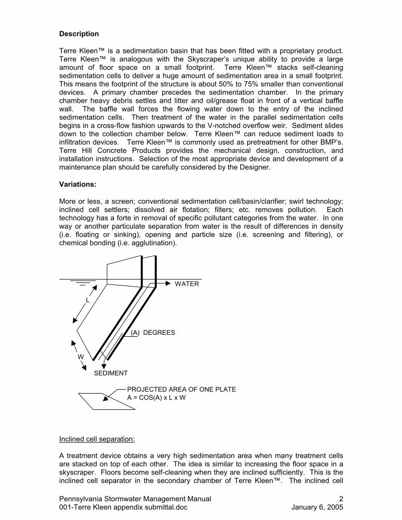
Terre Kleen� is a sedimentation basin that has been fitted with a proprietary product. Terre Kleen� is analogous with the Skyscraper�s unique ability to provide a large amount of floor space on a small footprint. Terre Kleen� stacks self-cleaning sedimentation cells to deliver a huge amount of sedimentation area in a small footprint. This means the footprint of the structure is about 50% to 75% smaller than conventional devices. A primary chamber precedes the sedimentation chamber. In the primary chamber heavy debris settles and litter and oil/grease float in front of a vertical baffle wall. The baffle wall forces the flowing water down to the entry of the inclined sedimentation cells. Then treatment of the water in the parallel sedimentation cells begins in a cross-flow fashion upwards to the V-notched overflow weir. Sediment slides down to the collection chamber below. Terre Kleen� can reduce sediment loads to infiltration devices. Terre Kleen� is commonly used as pretreatment for other BMP�s. Terre Hill Concrete Products provides the mechanical design, construction, and installation instructions. Selection of the most appropriate device and development of a maintenance plan should be carefully considered by the Designer.
Variations:
More or less, a screen; conventional sedimentation cell/basin/clarifier; swirl technology; inclined cell settlers; dissolved air flotation; filters; etc. removes pollution. Each technology has a forte in removal of specific pollutant categories from the water. In one way or another particulate separation from water is the result of differences in density (i.e. floating or sinking), opening and particle size (i.e. screening and filtering), or chemical bonding (i.e. agglutination).
WATER
L
(A) DEGREES
W
SEDIMENT
PROJECTED AREA OF ONE PLATEA = COS(A) x L x W
Inclined cell separation: A treatment device obtains a very high sedimentation area when many treatment cells are stacked on top of each other. The idea is similar to increasing the floor space in a skyscraper. Floors become self-cleaning when they are inclined sufficiently. This is the inclined cell separator in the secondary chamber of Terre Kleen�. The inclined cell
Pennsylvania Stormwater Management Manual 2 001-Terre Kleen appendix submittal.doc January 6, 2005
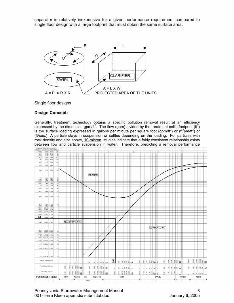
separator is relatively inexpensive for a given performance requirement compared to single floor design with a large footprint that must obtain the same surface area.
R L
W
A = L X WA = PI X R X R PROJECTED AREA OF THE UNITS
SWIRLCLARIFIER
Single floor designs Design Concept:
Generally, treatment technology obtains a specific pollution removal result at an efficiency expressed by the dimension gpm/ft2. The flow (gpm) divided by the treatment cell�s footprint (ft2) is the surface loading expressed in gallons per minute per square foot (gpm/ft2) or (ft3pm/ft2) or (ft/sec.) A particle stays in suspension or settles depending on the loading. For particles with rock density and size above, 10-micron, studies indicate that a fairly consistent relationship exists between flow and particle suspension in water. Therefore, predicting a removal performance
Pennsylvania Stormwater Management Manual 3 001-Terre Kleen appendix submittal.doc January 6, 2005
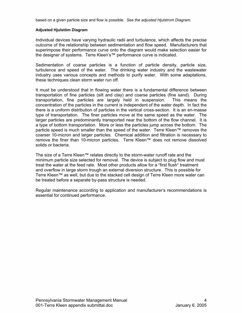
based on a given particle size and flow is possible. See the adjusted Hjulstrom Diagram.
Adjusted Hjulstöm Diagram
Individual devices have varying hydraulic radii and turbulence, which affects the precise outcome of the relationship between sedimentation and flow speed. Manufacturers that superimpose their performance curve onto the diagram would make selection easier for the designer of systems. Terre Kleen�s� performance curve is indicated. Sedimentation of coarse particles is a function of particle density, particle size, turbulence and speed of the water. The drinking water industry and the wastewater industry uses various concepts and methods to purify water. With some adaptations, these techniques clean storm water run off. It must be understood that in flowing water there is a fundamental difference between transportation of fine particles (silt and clay) and coarse particles (fine sand). During transportation, fine particles are largely held in suspension. This means the concentration of the particles in the current is independent of the water depth. In fact the there is a uniform distribution of particles in the vertical cross-section. It is an en-masse type of transportation. The finer particles move at the same speed as the water. The larger particles are predominantly transported near the bottom of the flow channel. It is a type of bottom transportation. More or less the particles jump across the bottom. The particle speed is much smaller than the speed of the water. Terre Kleen� removes the coarser 10-micron and larger particles. Chemical addition and filtration is necessary to remove the finer than 10-micron particles. Terre Kleen� does not remove dissolved solids or bacteria. The size of a Terre Kleen� relates directly to the storm-water runoff rate and the minimum particle size selected for removal. The device is subject to plug flow and must treat the water at the feed rate. Most other products allow for a �first flush� treatment and overflow in large storm trough an external diversion structure. This is possible for Terre Kleen� as well, but due to the stacked cell design of Terre Kleen more water can be treated before a separate by-pass structure is needed.
Regular maintenance according to application and manufacturer�s recommendations is essential for continued performance.
Pennsylvania Stormwater Management Manual 4 001-Terre Kleen appendix submittal.doc January 6, 2005
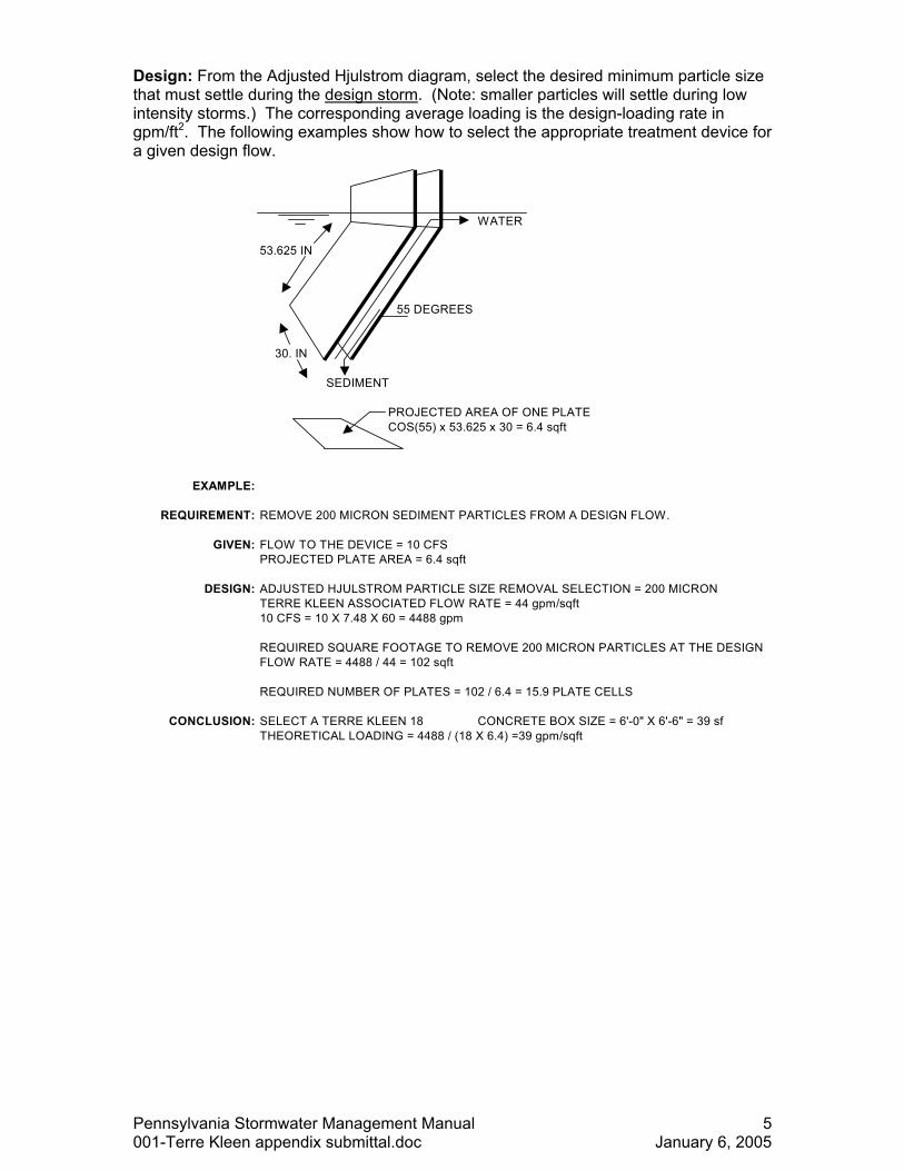
Design: From the Adjusted Hjulstrom diagram, select the desired minimum particle size that must settle during the design storm. (Note: smaller particles will settle during low intensity storms.) The corresponding average loading is the design-loading rate in gpm/ft2. The following examples show how to select the appropriate treatment device for a given design flow.
WATER
53.625 IN
55 DEGREES
30. IN
SEDIMENT
PROJECTED AREA OF ONE PLATECOS(55) x 53.625 x 30 = 6.4 sqft
EXAMPLE:
REQUIREMENT: REMOVE 200 MICRON SEDIMENT PARTICLES FROM A DESIGN FLOW.
GIVEN: FLOW TO THE DEVICE = 10 CFSPROJECTED PLATE AREA = 6.4 sqft
DESIGN: ADJUSTED HJULSTROM PARTICLE SIZE REMOVAL SELECTION = 200 MICRONTERRE KLEEN ASSOCIATED FLOW RATE = 44 gpm/sqft10 CFS = 10 X 7.48 X 60 = 4488 gpm
REQUIRED SQUARE FOOTAGE TO REMOVE 200 MICRON PARTICLES AT THE DESIGNFLOW RATE = 4488 / 44 = 102 sqft
REQUIRED NUMBER OF PLATES = 102 / 6.4 = 15.9 PLATE CELLS
CONCLUSION: SELECT A TERRE KLEEN 18 CONCRETE BOX SIZE = 6'-0" X 6'-6" = 39 sfTHEORETICAL LOADING = 4488 / (18 X 6.4) =39 gpm/sqft
Pennsylvania Stormwater Management Manual 5 001-Terre Kleen appendix submittal.doc January 6, 2005
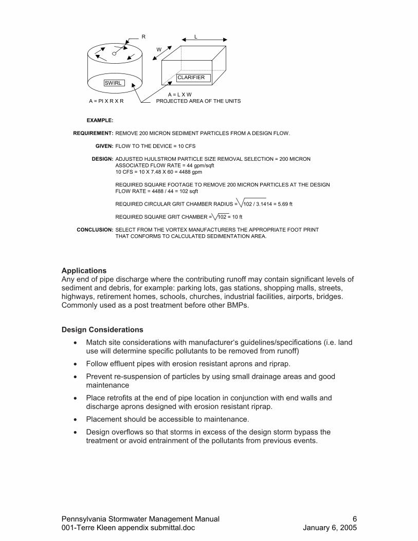
R L
W
A = L X WA = PI X R X R PROJECTED AREA OF THE UNITS
EXAMPLE:
REQUIREMENT: REMOVE 200 MICRON SEDIMENT PARTICLES FROM A DESIGN FLOW.
GIVEN: FLOW TO THE DEVICE = 10 CFS
DESIGN: ADJUSTED HJULSTROM PARTICLE SIZE REMOVAL SELECTION = 200 MICRONASSOCIATED FLOW RATE = 44 gpm/sqft10 CFS = 10 X 7.48 X 60 = 4488 gpm
REQUIRED SQUARE FOOTAGE TO REMOVE 200 MICRON PARTICLES AT THE DESIGNFLOW RATE = 4488 / 44 = 102 sqft
REQUIRED CIRCULAR GRIT CHAMBER RADIUS = 102 / 3.1414 = 5.69 ft
REQUIRED SQUARE GRIT CHAMBER = 102 = 10 ft
CONCLUSION: SELECT FROM THE VORTEX MANUFACTURERS THE APPROPRIATE FOOT PRINTTHAT CONFORMS TO CALCULATED SEDIMENTATION AREA.
SWIRLCLARIFIER
Applications Any end of pipe discharge where the contributing runoff may contain significant levels of sediment and debris, for example: parking lots, gas stations, shopping malls, streets, highways, retirement homes, schools, churches, industrial facilities, airports, bridges. Commonly used as a post treatment before other BMPs. Design Considerations
• Match site considerations with manufacturer�s guidelines/specifications (i.e. land use will determine specific pollutants to be removed from runoff)
• Follow effluent pipes with erosion resistant aprons and riprap. • Prevent re-suspension of particles by using small drainage areas and good
maintenance • Place retrofits at the end of pipe location in conjunction with end walls and
discharge aprons designed with erosion resistant riprap. • Placement should be accessible to maintenance. • Design overflows so that storms in excess of the design storm bypass the
treatment or avoid entrainment of the pollutants from previous events.
Pennsylvania Stormwater Management Manual 6 001-Terre Kleen appendix submittal.doc January 6, 2005
Detailed Stormwater Functions
Volume Reduction Calculations: N/A
Peak Rate Mitigation Calculations: N/A
Water Quality Improvement: If sized to treat the WQ storm, removal rates above can be applied to that volume of water.
Construction Sequence
1. Stabilize all contributing areas before installing and connecting pipes to these TERRE KLEEN��s.
2. Follow manufacturer�s guidelines for installation. Do not use TERRE KLEEN��s during construction unless product is designed for it. (Some products have adsorption components that should be installed for post-construction events.)
Maintenance Issues
Post-construction, they should be emptied when full of sediment (and trash) and cleaned at least twice a year. They should also be inspected after significant precipitation. Maintenance is crucial to the effectiveness of this BMP. The more frequent TERRE KLEEN� is cleaned, the more effective it will be. Some sites have found that keeping a log of sediment amount and date removed is helpful in planning a maintenance schedule. The EPA has a monitoring program, Environmental Technology Verification (ETV) Program, (www.epa.gov/etv), that may be available to assist with the development of a monitoring plan.
Follow the manufacturer�s guidelines for maintenance, also taking into account expected pollutant load and site conditions.
The captured trash, oils, and sediments are stored in the unit itself. After a time period, these pollutants need to be removed from the structure. Inspection and maintenance are a routine part of ensuring the TERRE KLEEN� unit functions as designed and continues to remove the desired pollutants from the stormwater. Note: The TERRE KLEEN� unit is designed to be inspected and cleaned from grade. If entry into the TERRE KLEEN� unit is required, it will need to be performed by qualified personnel who are properly trained for confined space activity using proper equipment a/p the latest OSHA regulations. The TERRE KLEEN� will trap floatable litter and oils that are not emulsified in the stormwater runoff. Keep sparks and open flames away when working around a TERRE KLEEN� unit that may contain flammable material. Terre Hill Concrete Products
Pennsylvania Stormwater Management Manual 7 001-Terre Kleen appendix submittal.doc January 6, 2005
recommends the use of oil absorption booms that solidify collected hydrocarbons in the primary chamber. These booms float and sink deeper as oil is absorbed. The booms or blankets must be replaced during the cleaning cycles. When a TERRE KLEEN� unit is newly installed, frequent inspection is highly recommended. The design of the TERRE KLEEN� unit permits easy inspection. It is recommended that during the first two years after installation, inspections be performed at least quarterly for the purpose of noting the rate of sediment and floatable accumulation. A form for recording information resulting from the inspection is highly recommended. Utilizing a form provides a history of the pollutant accumulation for the TERRE KLEEN� unit and as a comparison to other TERRE KLEEN� units that are in use in a region. To determine sediment accumulation, a stadia rod or similar measuring device may be used. Cleaning is recommended when the sediment is found to be at the level shown in the manufacturer�s literature. To avoid underestimating the volume of sediment in the chamber, care must be exercised in lowering the measuring device to the top of the sediment pile. A Vactor truck, or similar trailer mounted equipment, can be used to clean. Disposal of removed material will depend on the nature of the drainage area and the intent and function of the TERRE KLEEN�. Reportedly, in Harrisburg, PA, sediment collected from inlets by a Vactor-truck is disposed at a landfill after the liquid fraction is decanted at a sewage treatment facility. Material removed from TERRE KLEEN��s that serve �Hot Spots� such as fueling stations or that receive a large amount of debris should be handling according to DEP regulations for solid waste, such as a landfill that is approved by DEP to accept solid waste. TERRE KLEEN��s that primary catch sediment and detritus from areas such as lawns may reuse the waste on site, which is recommended by the DEP.
Winter Concerns: There is limited data studying cold weather effects on TERRE KLEEN��s effectiveness. Freezing conditions are similar to conditions that septic tanks are exposed to. The surrounding soil and the depth of the structure insulate the structure. When inlets are used as part of the TERRE KLEEN�, exposure to freezing may become an issue and may result in more runoff bypassing the treatment system and overflowing. Salt stratification may also reduce detention time. Colder temperatures reduce the settling velocity of particles, which can result in fewer particles being �trapped�. Salt and sand is significantly increased in the winter, and may warrant more frequent maintenance, but sometimes freezing makes accessing devices for maintenance difficult
Cost Issues
TERRE KLEEN��s range from $200-$500 per square foot of required surface sedimentation area and technology selected.
Pennsylvania Stormwater Management Manual 8 001-Terre Kleen appendix submittal.doc January 6, 2005
Specifications:
SECTION _____
SPECIFICATION FOR TERRE KLEEN� HYDRODYNAMIC SEPARATOR
BY TERRE HILL CONCRETE PRODUCTS 485 WEAVERLAND VALLEY ROAD
TERRE HILL, PA 17581 TEL.: (717) 445-3100 FAX: (717) 445-3108.
This specification is available on disk and by E-mail. Verify and request the latest version of this specification before use.
PART 1-GENERAL 1.1 DESCRIPTION
A. This work shall consist of furnishing and installing a Hydrodynamic Separator at each location as shown on the contract plans. Each unit includes an oil and debris separation chamber followed by an inclined cell separation unit in a secondary chamber that is fed through an opening in the divider wall between the two chambers. This product is produced by Terre Hill Concrete Products under the name �Terre Kleen��. All rights are reserved.
B. The separator shall operate based on the hydrostatic pressure
differential between the inlet and outlet pipe. The opening in the divider wall shall not cause scouring and re-suspension of fine sediment below the settling cells.
C. Each separation chamber shall be accessible through removable
covers at grade for the removal of the settled solids and floating particulates.
D. A by-pass opening shall permit excess storm water to flow underneath
a baffle wall and over the top of the inclined cells for flows that exceed the design flow of the device.
1.2 SUBMITTALS
Pennsylvania Stormwater Management Manual 9 001-Terre Kleen appendix submittal.doc January 6, 2005
A. Shop drawings shall be submitted as described in Division 1 � General Requirements.
B. Certifications shall be submitted that the structures conform to the
standards listed in this Section. 1.3 REFERENCES
A. ASTM International ( ASTM ): A48 Specification for Gray Iron Castings C32 Specification for Sewer and Manhole Brick C270 Specification for Mortar for Unit Masonry C478 Specification for Precast Reinforced Concrete Manhole Sections C913 Standard Specification for Precast Concrete Water and
Wastewater Structures US Patent No. 6676832 B2; Surface water purifying catch basin.
B. Federal Specifications ( FS ): FS-SS-S-210 Sealing Compound, Preformed Plastic for Expansion
Joints and Pipe Joints 1.4 MANUFACTURERS
A. The products furnished by named manufacturers are specified as a standard of quality and performance.
B. The manufacturer of the concrete structure shall be certified by the
National Precast Concrete Association (NPCA). C. The manufacturer of the Terre-Kleen� shall be licensed to produce
and or sell the entire separator or components thereof by Terre Hill Concrete Products of Terre Hill Pennsylvania 717-445-3100.
PART 2- PRODUCTS 2.1 MATERIALS AND DESIGN
A. The reinforced concrete vault structure shall be designed for HS20-44 traffic loading, soil pressure, ground water pressure and buoyancy. The materials and structural design shall be per ASTM C478 and ASTM C913. The concrete shall have a minimum compressive strength of 4000 psi.
B. The access cover shall be designed for HS25 (MS-18 plus 25%) traffic
loading and shall provide a minimum of 27 1/2 inches clear opening.
Pennsylvania Stormwater Management Manual 10 001-Terre Kleen appendix submittal.doc January 6, 2005
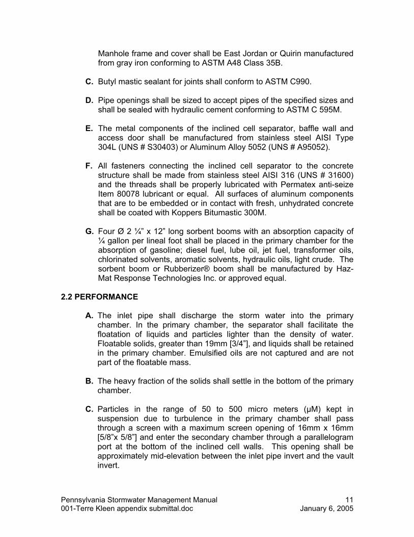
Manhole frame and cover shall be East Jordan or Quirin manufactured from gray iron conforming to ASTM A48 Class 35B.
C. Butyl mastic sealant for joints shall conform to ASTM C990.
D. Pipe openings shall be sized to accept pipes of the specified sizes and
shall be sealed with hydraulic cement conforming to ASTM C 595M.
E. The metal components of the inclined cell separator, baffle wall and access door shall be manufactured from stainless steel AISI Type 304L (UNS # S30403) or Aluminum Alloy 5052 (UNS # A95052).
F. All fasteners connecting the inclined cell separator to the concrete
structure shall be made from stainless steel AISI 316 (UNS # 31600) and the threads shall be properly lubricated with Permatex anti-seize Item 80078 lubricant or equal. All surfaces of aluminum components that are to be embedded or in contact with fresh, unhydrated concrete shall be coated with Koppers Bitumastic 300M.
G. Four Ø 2 ¼� x 12� long sorbent booms with an absorption capacity of
¼ gallon per lineal foot shall be placed in the primary chamber for the absorption of gasoline; diesel fuel, lube oil, jet fuel, transformer oils, chlorinated solvents, aromatic solvents, hydraulic oils, light crude. The sorbent boom or Rubberizer® boom shall be manufactured by Haz-Mat Response Technologies Inc. or approved equal.
2.2 PERFORMANCE
A. The inlet pipe shall discharge the storm water into the primary chamber. In the primary chamber, the separator shall facilitate the floatation of liquids and particles lighter than the density of water. Floatable solids, greater than 19mm [3/4�], and liquids shall be retained in the primary chamber. Emulsified oils are not captured and are not part of the floatable mass.
B. The heavy fraction of the solids shall settle in the bottom of the primary
chamber.
C. Particles in the range of 50 to 500 micro meters (µM) kept in suspension due to turbulence in the primary chamber shall pass through a screen with a maximum screen opening of 16mm x 16mm [5/8�x 5/8�] and enter the secondary chamber through a parallelogram port at the bottom of the inclined cell walls. This opening shall be approximately mid-elevation between the inlet pipe invert and the vault invert.
Pennsylvania Stormwater Management Manual 11 001-Terre Kleen appendix submittal.doc January 6, 2005
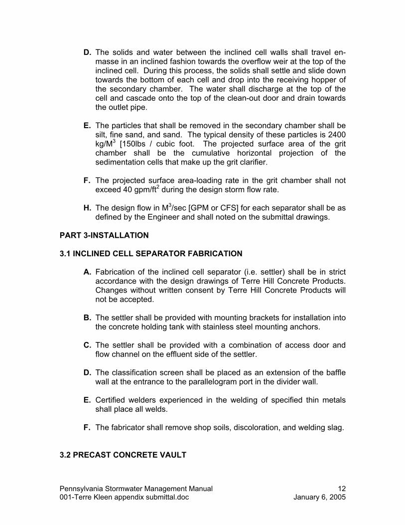
D. The solids and water between the inclined cell walls shall travel en-masse in an inclined fashion towards the overflow weir at the top of the inclined cell. During this process, the solids shall settle and slide down towards the bottom of each cell and drop into the receiving hopper of the secondary chamber. The water shall discharge at the top of the cell and cascade onto the top of the clean-out door and drain towards the outlet pipe.
E. The particles that shall be removed in the secondary chamber shall be
silt, fine sand, and sand. The typical density of these particles is 2400 kg/M3 [150lbs / cubic foot. The projected surface area of the grit chamber shall be the cumulative horizontal projection of the sedimentation cells that make up the grit clarifier.
F. The projected surface area-loading rate in the grit chamber shall not
exceed 40 gpm/ft2 during the design storm flow rate.
H. The design flow in M3/sec [GPM or CFS] for each separator shall be as defined by the Engineer and shall noted on the submittal drawings.
PART 3-INSTALLATION 3.1 INCLINED CELL SEPARATOR FABRICATION
A. Fabrication of the inclined cell separator (i.e. settler) shall be in strict accordance with the design drawings of Terre Hill Concrete Products. Changes without written consent by Terre Hill Concrete Products will not be accepted.
B. The settler shall be provided with mounting brackets for installation into
the concrete holding tank with stainless steel mounting anchors.
C. The settler shall be provided with a combination of access door and flow channel on the effluent side of the settler.
D. The classification screen shall be placed as an extension of the baffle
wall at the entrance to the parallelogram port in the divider wall.
E. Certified welders experienced in the welding of specified thin metals shall place all welds.
F. The fabricator shall remove shop soils, discoloration, and welding slag.
3.2 PRECAST CONCRETE VAULT
Pennsylvania Stormwater Management Manual 12 001-Terre Kleen appendix submittal.doc January 6, 2005
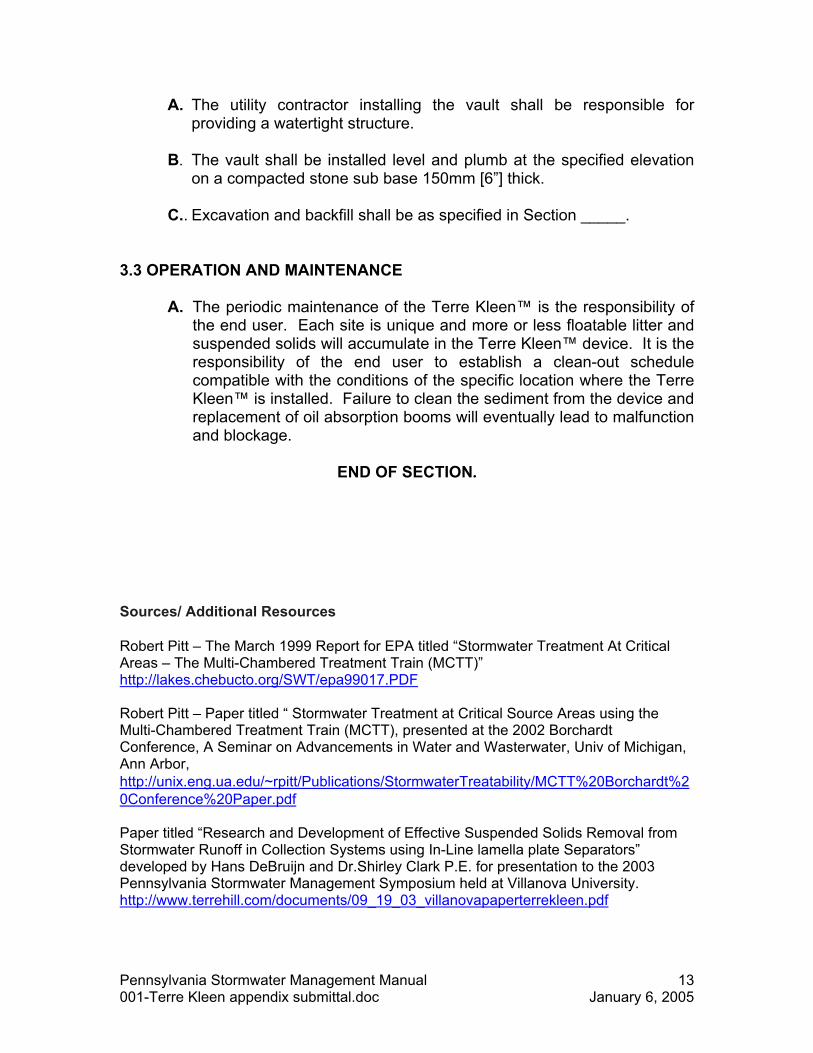
A. The utility contractor installing the vault shall be responsible for providing a watertight structure.
B. The vault shall be installed level and plumb at the specified elevation
on a compacted stone sub base 150mm [6�] thick.
C.. Excavation and backfill shall be as specified in Section _____.
3.3 OPERATION AND MAINTENANCE
A. The periodic maintenance of the Terre Kleen� is the responsibility of
the end user. Each site is unique and more or less floatable litter and suspended solids will accumulate in the Terre Kleen� device. It is the responsibility of the end user to establish a clean-out schedule compatible with the conditions of the specific location where the Terre Kleen� is installed. Failure to clean the sediment from the device and replacement of oil absorption booms will eventually lead to malfunction and blockage.
END OF SECTION.
Sources/ Additional Resources
Robert Pitt � The March 1999 Report for EPA titled �Stormwater Treatment At Critical Areas � The Multi-Chambered Treatment Train (MCTT)� http://lakes.chebucto.org/SWT/epa99017.PDF Robert Pitt � Paper titled � Stormwater Treatment at Critical Source Areas using the Multi-Chambered Treatment Train (MCTT), presented at the 2002 Borchardt Conference, A Seminar on Advancements in Water and Wasterwater, Univ of Michigan, Ann Arbor, http://unix.eng.ua.edu/~rpitt/Publications/StormwaterTreatability/MCTT%20Borchardt%20Conference%20Paper.pdf Paper titled �Research and Development of Effective Suspended Solids Removal from Stormwater Runoff in Collection Systems using In-Line lamella plate Separators� developed by Hans DeBruijn and Dr.Shirley Clark P.E. for presentation to the 2003 Pennsylvania Stormwater Management Symposium held at Villanova University. http://www.terrehill.com/documents/09_19_03_villanovapaperterrekleen.pdf
Pennsylvania Stormwater Management Manual 13 001-Terre Kleen appendix submittal.doc January 6, 2005

Design information: Fact sheets:
Pennsylvania Stormwater Management Manual 14 001-Terre Kleen appendix submittal.doc January 6, 2005