Embed Size (px)
Citation preview
ANALYSES OF SOME CEMENT BRANDS IN THE NIGERIAN MARKET
Digitally Signed by: Content manager’s
DN : CN = Weabmaster’s name
O= University of Nigeria, Nsukka
OU = Innovation Centre
ORJI ANN N.
Faculty of Physical Sciences
Department of Pure &Industi
Chemistry
ANALYSES OF SOME CEMENT BRANDS IN THE NIGERIAN MARKET
AND OPTIMIZATION OF LIMESTONE CONTENT OF
LIMESTONE COMPOSITE PORTLAND CEMENT
TYOPINE ANDREW AONDOAVER
B.Sc , M.Sc (BSU)
PG/Ph.D/09/51796
i
: Content manager’s Name
Weabmaster’s name
a, Nsukka
Department of Pure &Industiral
ANALYSES OF SOME CEMENT BRANDS IN THE NIGERIAN MARKET
AND OPTIMIZATION OF LIMESTONE CONTENT OF
LIMESTONE COMPOSITE PORTLAND CEMENT
TYOPINE ANDREW AONDOAVER
ii
ANA TYOPINE ANDREW AONDOAVER
B.Sc , M.Sc (BSU)
PG/Ph.D/09/51796
LYSES OF SOME CEMENT BRANDS IN THE
NIGERIAN MARKET AND OPTIMIZATION OF
LIMESTONE CONTENT OF LIMESTONE
COMPOSITE PORTLAND CEMENT
BY
TYOPINE ANDREW AONDOAVER
B.Sc , M.Sc (BSU)
PG/Ph.D/09/51796
A THESIS PRESENTED TO THE DEPARTMENT OF
PURE AND INDUSTRIAL CHEMISTRY,
FACULTY OF PHYSICAL SCIENCES,
UNIVERSITY OF NIGERIA, NSUKKA
IN
PARTIAL FULFILLMENT OF THE
REQUIREMENTS FOR THE DEGREE OF
DOCTOR OF PHILOSOPHY OF THE
UNIVERSITY OF NIGERIA, NSUKKA
iii
JUNE, 2014
CERTIFICATION
We certify that this Ph.D research work titled “Analyses of some brands of cement in the
Nigerian market and optimization of limestone content of limestone composite Portland
cement” was undertaken and reported by TYOPINE ANDREW AONDOAVER
(PG/Ph.D/09/51796).
Supervisor Prof.C.O.B. Okoye ---------------------------------- -------------
Signature Date
Head of Department Prof. P.O. Ukoha ------------------------------- -------------
Signature Date

iv
DEDICATION
To all youths passionate about learning
To Akaadoo
To service to humanity

v
ACKNOWLEDGEMENTS
God is Almighty, merciful and kind, for through his kindness we are able to do all things. I
want to thank God for his mercies and protection throughout this work.
I gratefully appreciate the contributions of the following persons towards the success of this
research work:
• My supervisor, Prof. C.O.B. Okoye for indefatigably mentoring and supervising the
research work from beginning to the end
• The Head of Department , Prof. P.O. Ukoha
• My father, friend and mentor, Dr. V.E. Agbazue
• My colleagues and friends as the case may be for their moral and technical support;
Doose Akaakase, Denen Ende, Peter Agudu, Iorbee Terfa, Blessing Ocheni, Denis
Dura, Vincent Ikyuior, Okon Bassey, Mr .M.O. Abifarin, Kumafan Dzaan, Akosu
Joy, Fefa Joseph, Ishom Isaac, Akulegwa Igbalumun, Silas Avenda, Andrew Ada,
Engr. &Mrs Ade sugh, Dr. Omaka (HOD Chemistry Department, FUNAI), Anthony
Ekenia, Mrs Ada Nkwo, Nora Igbalumun, Dido Mann, Raymond Aernyi, Edward Nor
and all those that have not been mentioned for want of space
• My family: Tina (Wife), David (son) and Queen (daughter), Mr & Mrs E.T. Imande
(parents), Maureen Tyopine, Sandra Tyopine, Dorothy Tyopine and Timothy Tyopine
(siblings) for enduring patiently while this work lasted.
vi
TABLE OF CONTENTS
Title i
Certification ii
Dedication iii
Acknowledgements iv
Table of contents v
Table of abbreviations x
List of figures xi
List of tables xii
Abstract xiv
1.0 Chapter one: Introduction 1
1.1 The nature of cement 1
1.2 World cement production and consumption 1
1.3 Cement production in Nigeria 2
1.4 Limestone composite cement 2
1.5 Statement of the problem 3
1.6 Significance of the study 3
1.7 Aims and objectives of the study 4
1.8 Scope of the study 4
2.0 Chapter two: Literature Review 6
2.1 History of cement production 6
2.1.1 Production of Portland cement 6
2.1.2 Sources of raw materials for cement manufacture in Nigeria 7
2.2 Chemical composition of raw materials for cement production 8
2.2.1 Limestone 8
2.2.2 Clays 10
2.2.3 Minor and trace components 12
2.2.3.1 Magnesia, MgO 12
2.2.3.2 Alkalis 13
vii
2.2.3.3 Sulphur 13
2.2.3.4 Phosphorus 13
2.3 Types of Portland cement 14
2.3.1 Type 1 14
2.3.2 Type 2 14
2.3.3 Type 3 14
2.3.4 Type 4 15
2.3.5 Type 5 15
2.3.6 Other types of cements 16
2.3.6.1 Coloured cements 16
2.3.6.2 Air entrained cements 16
2.3.6.3 Masonry cements 16
2.3.6.4 Water proof cements 16
2.3.6.5 Hydrophobic cements 17
2.3.6.6 Oil wel l cements 17
2.3.6.7 Slag cements 17
2.3.6.8 High alumina cements 17
2.4 Composition of Portland cement 18
2.5 Estimation of clinker composition 18
2.6 Setting of Portland cement 19
2.7 Manufacture of Portland cement 20
2.7.1 Pre-blending of raw materials 20
2.7.2 Heat treatment 22
2.7.3 Clinker cooling and grinding 29
2.8 Properties of Portland cement 30
2.8.1 Fineness 30
2.8.1.1 ASTM C 115: Fineness of Portland cement by the turbidimeter 30
2.8.1.2 ASTM C 204: Fineness of hydraulic cement by air permeability apparatus 31
2.8.2 Soundness 31
2.8.3 Setting time 32
2.8.4 Strength 34
2.8.5 Loss on ignition 35
2.8.6 Specific gravity 35
2.8.7 Heat of hydration 35
viii
2.9 Environmental impact 36
2.9.1 CO2 emissions 36
2.9.2 Heavy metal emission into the atmosphere 36
2.9.3 Alternative fuels and by product materials 36
2.10 Cement in Nigeria 37
2.11 Blended cements 39
2.12 Supplementary materials used in the manufacture of blended cements 40
2.12.1 High calcium fly ash 40
2.12.2 Ground granulated blast furnace slag 40
2.12.3 Condensed silica fume 40
2.12.4 Rice husk ash 41
2.12.5 Volcanic ash 41
2.13 Benefits of blended (composite) cement 41
2.13.1 Economical benefit 41
2.13.2 Technical benefits 41
2.13.3 Environmental benefits 42
2.14 Limestone as a supplementary material in blended cement production 42
2.15 Effect of limestone on properties of Portland cement 43
2.15.1 Particle size distribution and fineness 43
2.15.2 Consistency 44
2.15.3 Hydration 45
2.15.4 Setting 50
2.15.5 Compressive strength 50
2.16 Limestone reactions in limestone cements 51
2.17 Effect of limestone on concrete properties 52
2.17.1 Workability 52
2.17.2 Sulphate resistance 53
3.0 Chapter three: Experimental 56
3.1 Materials and methods 56
3.1.1 Materials 56
3.1.2 Reagents 56
3.1.3 Apparatus 56
3.1.4 Material sampling and sample preparation 57
3.2 Methods 57
ix
3.2.1 Analysis of limestone 57
3.2.1.1 Determination of calcium carbonate in limestone 57
3.2.1.2 Determination of lime in limestone 57
3.2.1.3 Determination of loss on ignition 57
3.2.2 Analysis of gypsum 57
3.2.2.1 Determination of sulphite (SO3) 57
3.2.2.2 Determination of gypsum purity 58
3.2.3 Analysis of clinker 58
3.2.3.1 Determination of loss on ignition (LOI) and sulphite (SO3) of clinker 58
3.2.3.2 Determination of silica in clinker by baking method 58
3.2.3.3 Determination of iron (III) oxide and aluminium (III) oxide
in clinker by EDTA titration 59
3.2.3.4 Determination of calcium oxide in clinker by EDTA titration 59
3.2.3.5 Determination of free lime in clinker by hot ethylene glycol method 59
3.2.3.6 Estimation of clinker constituents using Bogue’s formulae 60
3.2.4 Preparation of Laboratory composite cements 60
3.3 Physical analyses of cements 60
3.3.1 Determination of water demand and consistency 61
3.3.2 Determination of setting time 61
3.3.3 Determination of soundness 61
3.3.4 Determination of cement residue (fineness) using sieve method 62
3.3.5 Determination of cement surface area using air permeability method 62
3.3.6 Determination of compressive strength 62
3.4 Chemical analyses of cements 64
3.5 Quality control and statistical treatment of data 64
4.0 Chapter four: Results and discussion 65
4.1 Results 65
4.2 Discussion 72
4.2.1 Clinker parent sample 72
4.2.2 Ordinary Portland cement (OPC) 73
4.2.3 Effect of added limestone on chemical composition of LCCs 74
4.2.4 Effect of added limestone on particle size and surface area 76
4.2.5 Effect of added limestone on soundness of Portland cement 78
x
4.2.6 Effect of added limestone on setting time and consistency
of Portland cement 78
4.2.7 Effect of added limestone on strength development of Portland cement 82
4.3 Comparison of some analysed market brands of cements MBCs 83
4.4 Conclusion 86
4.5 Recommendations 86
4.6 Contribution to knowledge 86
References 87
Appendices 93
xi
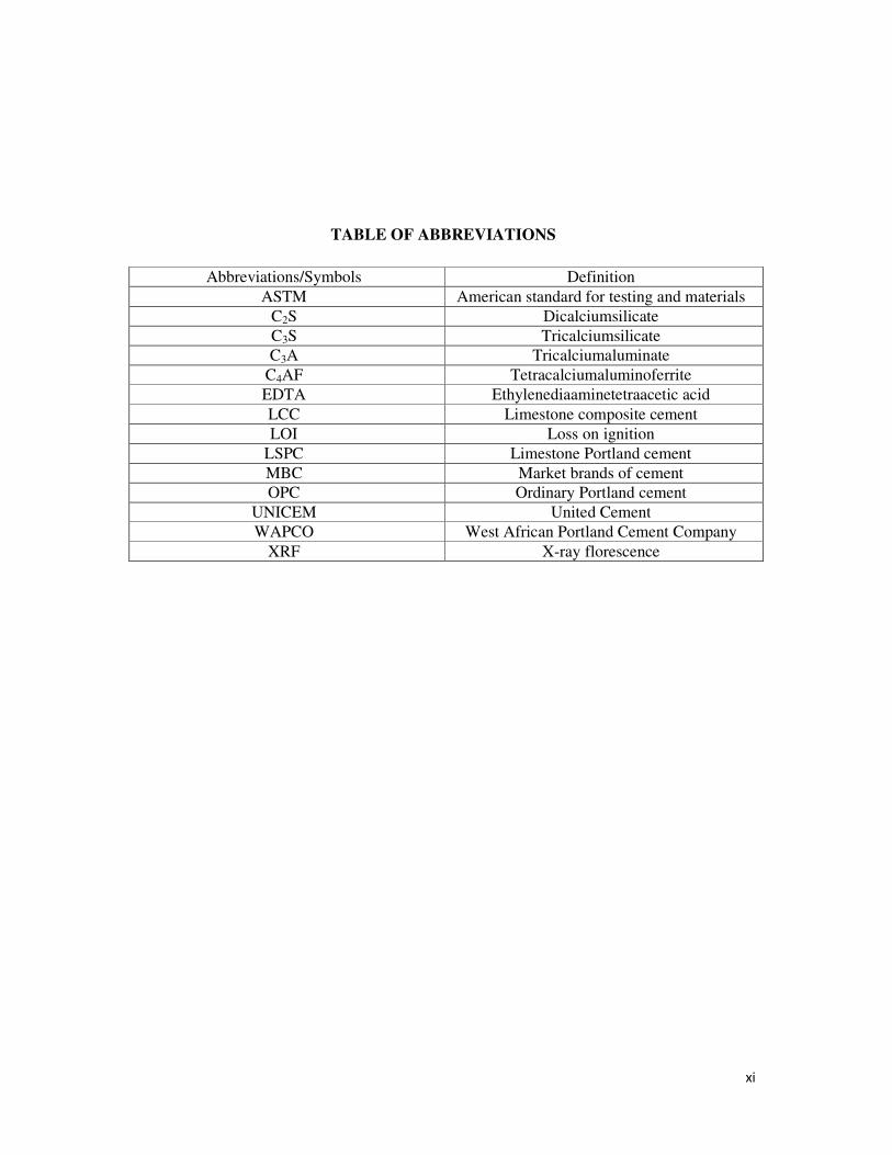
TABLE OF ABBREVIATIONS
Abbreviations/Symbols Definition
ASTM American standard for testing and materials
C2S Dicalciumsilicate
C3S Tricalciumsilicate
C3A Tricalciumaluminate
C4AF Tetracalciumaluminoferrite
EDTA Ethylenediaaminetetraacetic acid
LCC Limestone composite cement
LOI Loss on ignition
LSPC Limestone Portland cement
MBC Market brands of cement
OPC Ordinary Portland cement
UNICEM United Cement
WAPCO West African Portland Cement Company
XRF X-ray florescence
xii
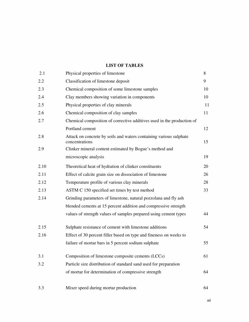
LIST OF TABLES
2.1 Physical properties of limestone 8
2.2 Classification of limestone deposit 9
2.3 Chemical composition of some limestone samples 10
2.4 Clay members showing variation in components 10
2.5 Physical properties of clay minerals 11
2.6 Chemical composition of clay samples 11
2.7 Chemical composition of corrective additives used in the production of
Portland cement 12
2.8 Attack on concrete by soils and waters containing various sulphate
concentrations 15
2.9 Clinker mineral content estimated by Bogue’s method and
microscopic analysis 19
2.10 Theoretical heat of hydration of clinker constituents 20
2.11 Effect of calcite grain size on dissociation of limestone 26
2.12 Temperature profile of various clay minerals 28
2.13 ASTM C 150 specified set times by test method 33
2.14 Grinding parameters of limestone, natural pozzolana and fly ash
blended cements at 15 percent addition and compressive strength
values of strength values of samples prepared using cement types 44
2.15 Sulphate resistance of cement with limestone additions 54
2.16 Effect of 30 percent filler based on type and fineness on weeks to
failure of mortar bars in 5 percent sodium sulphate 55
3.1 Composition of limestone composite cements (LCCs) 61
3.2 Particle size distribution of standard sand used for preparation
of mortar for determination of compressive strength 64
3.3 Mixer speed during mortar production 64
xiii
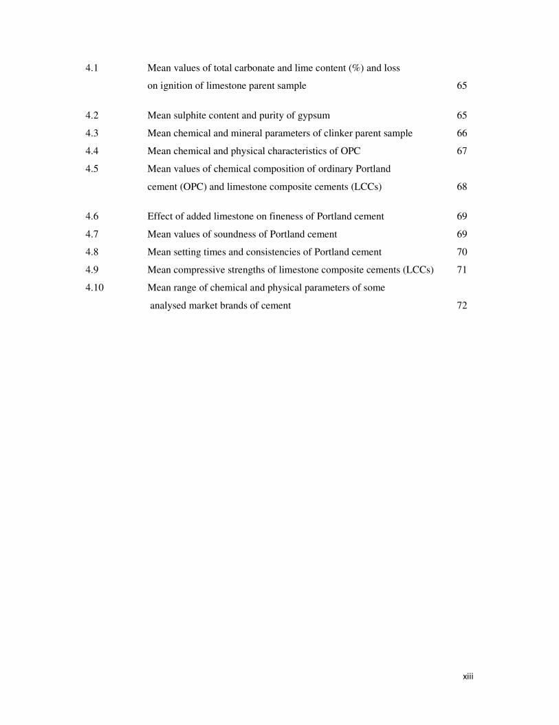
4.1 Mean values of total carbonate and lime content (%) and loss
on ignition of limestone parent sample 65
4.2 Mean sulphite content and purity of gypsum 65
4.3 Mean chemical and mineral parameters of clinker parent sample 66
4.4 Mean chemical and physical characteristics of OPC 67
4.5 Mean values of chemical composition of ordinary Portland
cement (OPC) and limestone composite cements (LCCs) 68
4.6 Effect of added limestone on fineness of Portland cement 69
4.7 Mean values of soundness of Portland cement 69
4.8 Mean setting times and consistencies of Portland cement 70
4.9 Mean compressive strengths of limestone composite cements (LCCs) 71
4.10 Mean range of chemical and physical parameters of some
analysed market brands of cement 72
xiv
LIST OF FIGURES
2.1 Schematic presentation of reactions in the kiln at various temperatures 23
2.2 Le Chatelier test apparatus 32
2.3 Vicat test apparatus for setting time 33
2.4a Compressive strength testing machine 34
2.4b Prism mortars for compressive strength test 34
2.4c Prism after fractured by load 35
2.5 Schematic presentation of rates of heat evolution 47
2.6 Heat evolution curves of ordinary Portland cement
blended with limestone 49
4.1 Effect of limestone addition on loss on ignition of Portland cement 74
4.2 Plot of freelime against % added limestone in Portland cement 75
4.3 Plot of sulphite against % added limestone in Portland cement 75
4.4a Plot of residue retained on 90µm and 180µm against
% added limestone in Portland cement 77
4.4b Plot of surface area of Portland cement against % added limestone
in Portland cement 77
4.5 Plot of consistency of Portland cement against % added limestone
in Portland cement 81
4.6 Plot of setting times of Portland cement against % added limestone
in Portland cement 81
4.7 Plot of strength development of Portland cement against
xv
% added limestone 83
4.8 Effect of added limestone on strength of cement 83
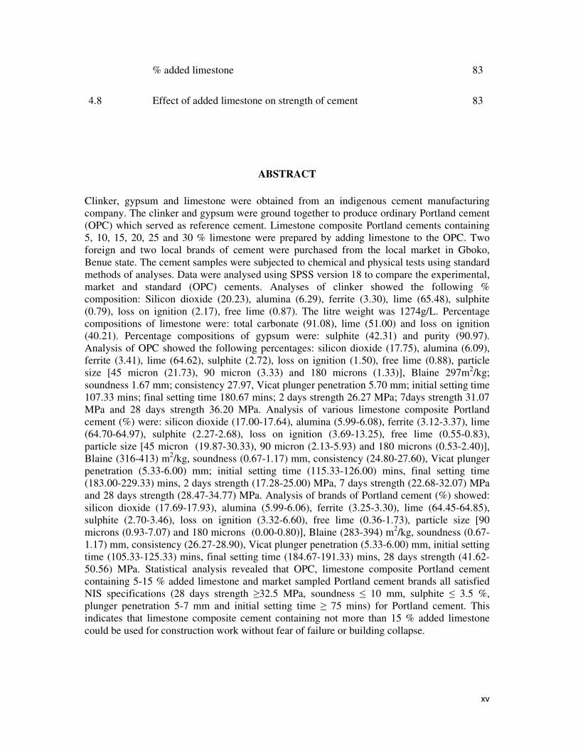
ABSTRACT
Clinker, gypsum and limestone were obtained from an indigenous cement manufacturing
company. The clinker and gypsum were ground together to produce ordinary Portland cement
(OPC) which served as reference cement. Limestone composite Portland cements containing
5, 10, 15, 20, 25 and 30 % limestone were prepared by adding limestone to the OPC. Two
foreign and two local brands of cement were purchased from the local market in Gboko,
Benue state. The cement samples were subjected to chemical and physical tests using standard
methods of analyses. Data were analysed using SPSS version 18 to compare the experimental,
market and standard (OPC) cements. Analyses of clinker showed the following %
composition: Silicon dioxide (20.23), alumina (6.29), ferrite (3.30), lime (65.48), sulphite
(0.79), loss on ignition (2.17), free lime (0.87). The litre weight was 1274g/L. Percentage
compositions of limestone were: total carbonate (91.08), lime (51.00) and loss on ignition
(40.21). Percentage compositions of gypsum were: sulphite (42.31) and purity (90.97).
Analysis of OPC showed the following percentages: silicon dioxide (17.75), alumina (6.09),
ferrite (3.41), lime (64.62), sulphite (2.72), loss on ignition (1.50), free lime (0.88), particle
size [45 micron (21.73), 90 micron (3.33) and 180 microns (1.33)], Blaine 297m2/kg;
soundness 1.67 mm; consistency 27.97, Vicat plunger penetration 5.70 mm; initial setting time
107.33 mins; final setting time 180.67 mins; 2 days strength 26.27 MPa; 7days strength 31.07
MPa and 28 days strength 36.20 MPa. Analysis of various limestone composite Portland
cement (%) were: silicon dioxide (17.00-17.64), alumina (5.99-6.08), ferrite (3.12-3.37), lime
(64.70-64.97), sulphite (2.27-2.68), loss on ignition (3.69-13.25), free lime (0.55-0.83),
particle size [45 micron (19.87-30.33), 90 micron (2.13-5.93) and 180 microns (0.53-2.40)],
Blaine (316-413) m2/kg, soundness (0.67-1.17) mm, consistency (24.80-27.60), Vicat plunger
penetration (5.33-6.00) mm; initial setting time (115.33-126.00) mins, final setting time
(183.00-229.33) mins, 2 days strength (17.28-25.00) MPa, 7 days strength (22.68-32.07) MPa
and 28 days strength (28.47-34.77) MPa. Analysis of brands of Portland cement (%) showed:
silicon dioxide (17.69-17.93), alumina (5.99-6.06), ferrite (3.25-3.30), lime (64.45-64.85),
sulphite (2.70-3.46), loss on ignition (3.32-6.60), free lime (0.36-1.73), particle size [90
microns (0.93-7.07) and 180 microns (0.00-0.80)], Blaine (283-394) m2/kg, soundness (0.67-
1.17) mm, consistency (26.27-28.90), Vicat plunger penetration (5.33-6.00) mm, initial setting
time (105.33-125.33) mins, final setting time (184.67-191.33) mins, 28 days strength (41.62-
50.56) MPa. Statistical analysis revealed that OPC, limestone composite Portland cement
containing 5-15 % added limestone and market sampled Portland cement brands all satisfied
NIS specifications (28 days strength ≥32.5 MPa, soundness ≤ 10 mm, sulphite ≤ 3.5 %,
plunger penetration 5-7 mm and initial setting time ≥ 75 mins) for Portland cement. This
indicates that limestone composite cement containing not more than 15 % added limestone
could be used for construction work without fear of failure or building collapse.

xvi
1
CHAPTER ONE
1.0 INTRODUCTION
1.1The Nature of Cement
Cement is the widest known building material in the civil industry. Cement is a substance
used to bind solid fragments or masses of solid matter together to form one whole substance
for the purpose of building, for example in making building blocks and concrete. By this
definition the term cement embraces a large number of different substances having adhesive
property. However popular use of the term cement has been restricted to adhesives used to
bind stones, bricks, tiles etc in the construction of buildings and other civil works1. These are
largely adhesives consisting of a mixture of compounds of lime as their principal
constituents. These are termed calcareous cements1. Cements of this kind are finely ground
powders which when mixed with water set into a hard mass. Setting and hardening result
from hydration, which is a chemical combination of the cement compounds with water. As a
result of their hydrating properties, constructional cements, which set and harden in the
presence of water, are called hydraulic cements. Among these is Portland cement 2. Cement is
applied as mortar and/or concrete. Mortar is used in binding bricks, blocks and stones in
walls. Concrete is used for large variety of constructional purposes which include road
construction and dams. Cement application as mortar or as concrete has helped in solving the
durability needs of infrastructure such as houses and offices, roads, bridges etc.
1.2 World Cement Production and Consumption
The need for modern housing has generally increased the demand for cement. Consequently,
cement production has grown exponentially over the years. In 2002, the world production of
hydraulic Portland cement was 1,800 million metric tons. The three top producers were China
with 704 million tons, India, with 100, and United States of America, with 91 million metric
tons. These three countries produce about half the world’s total production 3. In 2005, China
led with 43.46 percent followed by India producing 6.38 percent, then United States of
America with 4.38 percent. For the past 18 years, China has consistently produced more
cement than any other country in the world 3. This explains why China has the highest carbon
dioxide emission in the world. In 2006 it was established that China manufactured 1.24
billion tons of cement which was 44 percent of the world total cement production 5. Demand
2
for cement in China is expected to advance by 5.4 percent annually and this exceeded 1
billion tons in 2008. Cement consumption in China is expected to hit
44 percent of global demand and China will remain the world’s largest national consumer of
cement by a large margin 6.
As the demand for cement increased over the years different types of Portland cement
evolved in order to meet the demand. Type 1 or ordinary Portland cement (OPC) is the best
cement. It has the highest strength, but it is expensive. Therefore cheaper cements of less
strength or quality have been produced. These cements differ in their properties due to the
various supplementary materials added to the raw materials, namely; limestone and gypsum.
Examples of these supplementary materials include fly ash, pozzolana, slag, condensed silica
fume, volcanic ash, rice husk ash, and limestone 7. Countries such as Britain, Spain, France
and Argentina based on research results, have set standards for inclusion of supplementary
materials like limestone and other pozzolanic admixtures to OPC 7. For example British
Standards (BS 882) allows up to 15 % inclusion of limestone to OPC 8.
1.3 Cement Production in Nigeria
In Nigeria, The Federal Ministry of Commerce and Industry estimates that the effective
demand is around 20 million tons. According to Ian Furnivall and Tunde Abidoye 4, acute
infrastructure deficit and significant demand for housing has driven domestic production
volumes up to 25 % over the last four years 4. However the Federal government in her effort
to improve the availability of the commodity in 2010 banned the importation of cement into
the country in order to encourage local production and existing companies are increasing
their capacities. Dangote Cement Company formerly Benue Cement Company in Benue State
for instance, increased its capacity from 0.45 million to 2 million per annum in 2008 and now
2.9 to 3 million. In 2010 UNICEM added 2.5 million tons of its capacity to local capacity
while Lafarge WAPCO added 2.2 million tons in 2011. With these improved capacities the
quantity of cement in the market has improved.
1.4 Limestone Composite Cement
Limestone composite cement is widely used in Europe, in fact according to Cement Bureau,
the production of limestone composite cement in Europe increased by 7% between 2000 and
2010 9. This is partly due to its high durability, economic and environmental advantages. In
some European countries like Britain and Germany, up to 35 % limestone addition to
3
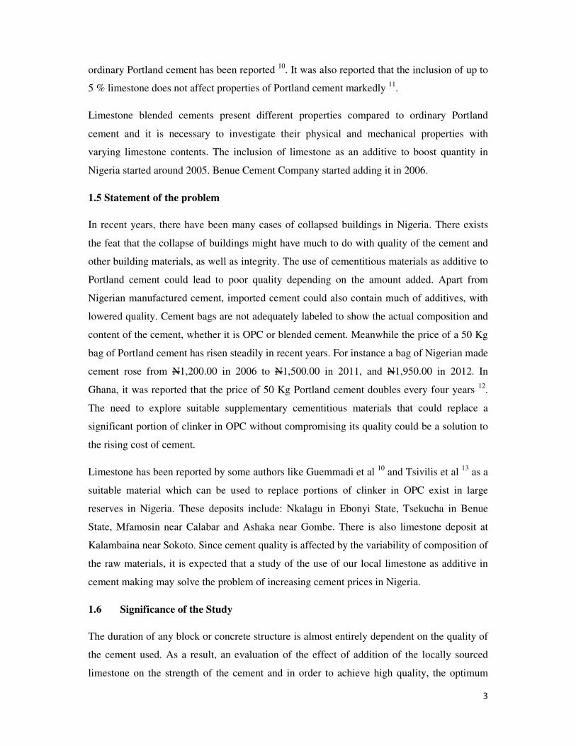
ordinary Portland cement has been reported 10
. It was also reported that the inclusion of up to
5 % limestone does not affect properties of Portland cement markedly 11
.
Limestone blended cements present different properties compared to ordinary Portland
cement and it is necessary to investigate their physical and mechanical properties with
varying limestone contents. The inclusion of limestone as an additive to boost quantity in
Nigeria started around 2005. Benue Cement Company started adding it in 2006.
1.5 Statement of the problem
In recent years, there have been many cases of collapsed buildings in Nigeria. There exists
the feat that the collapse of buildings might have much to do with quality of the cement and
other building materials, as well as integrity. The use of cementitious materials as additive to
Portland cement could lead to poor quality depending on the amount added. Apart from
Nigerian manufactured cement, imported cement could also contain much of additives, with
lowered quality. Cement bags are not adequately labeled to show the actual composition and
content of the cement, whether it is OPC or blended cement. Meanwhile the price of a 50 Kg
bag of Portland cement has risen steadily in recent years. For instance a bag of Nigerian made
cement rose from N1,200.00 in 2006 to N1,500.00 in 2011, and N1,950.00 in 2012. In
Ghana, it was reported that the price of 50 Kg Portland cement doubles every four years 12
.
The need to explore suitable supplementary cementitious materials that could replace a
significant portion of clinker in OPC without compromising its quality could be a solution to
the rising cost of cement.
Limestone has been reported by some authors like Guemmadi et al 10
and Tsivilis et al 13
as a
suitable material which can be used to replace portions of clinker in OPC exist in large
reserves in Nigeria. These deposits include: Nkalagu in Ebonyi State, Tsekucha in Benue
State, Mfamosin near Calabar and Ashaka near Gombe. There is also limestone deposit at
Kalambaina near Sokoto. Since cement quality is affected by the variability of composition of
the raw materials, it is expected that a study of the use of our local limestone as additive in
cement making may solve the problem of increasing cement prices in Nigeria.
1.6 Significance of the Study
The duration of any block or concrete structure is almost entirely dependent on the quality of
the cement used. As a result, an evaluation of the effect of addition of the locally sourced
limestone on the strength of the cement and in order to achieve high quality, the optimum
4
limestone content must be determined for production of high quality composite Portland
cement in Nigeria.
The present study is therefore an attempt to optimize limestone addition to Portland cement to
produce limestone composite Portland cement (LCPC) of comparable strength as OPC.
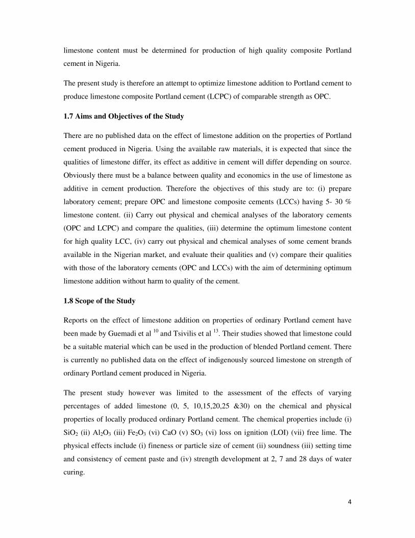
1.7 Aims and Objectives of the Study
There are no published data on the effect of limestone addition on the properties of Portland
cement produced in Nigeria. Using the available raw materials, it is expected that since the
qualities of limestone differ, its effect as additive in cement will differ depending on source.
Obviously there must be a balance between quality and economics in the use of limestone as
additive in cement production. Therefore the objectives of this study are to: (i) prepare
laboratory cement; prepare OPC and limestone composite cements (LCCs) having 5- 30 %
limestone content. (ii) Carry out physical and chemical analyses of the laboratory cements
(OPC and LCPC) and compare the qualities, (iii) determine the optimum limestone content
for high quality LCC, (iv) carry out physical and chemical analyses of some cement brands
available in the Nigerian market, and evaluate their qualities and (v) compare their qualities
with those of the laboratory cements (OPC and LCCs) with the aim of determining optimum
limestone addition without harm to quality of the cement.
1.8 Scope of the Study
Reports on the effect of limestone addition on properties of ordinary Portland cement have
been made by Guemadi et al 10
and Tsivilis et al 13
. Their studies showed that limestone could
be a suitable material which can be used in the production of blended Portland cement. There
is currently no published data on the effect of indigenously sourced limestone on strength of
ordinary Portland cement produced in Nigeria.
The present study however was limited to the assessment of the effects of varying
percentages of added limestone (0, 5, 10,15,20,25 &30) on the chemical and physical
properties of locally produced ordinary Portland cement. The chemical properties include (i)
SiO2 (ii) Al2O3 (iii) Fe2O3 (vi) CaO (v) SO3 (vi) loss on ignition (LOI) (vii) free lime. The
physical effects include (i) fineness or particle size of cement (ii) soundness (iii) setting time
and consistency of cement paste and (iv) strength development at 2, 7 and 28 days of water
curing.

5
Comparative study of four brands of Portland cement marketed in Nigeria with OPC and the
various LCCs was limited to their physical and chemical properties.

6
CHAPTER TWO
2.0 LITERATURE REVIEW
2.1 History of Cement Production
The history of cements dates back to the era of ancient Greece and Roman civilizations. The
materials used were lime and volcanic ash. These materials have hydraulicity by slowly
reacting in the presence of water to form a hard mass. This formed the cementing material of
the Roman mortars and concretes of over 2000 years ago and of subsequent construction
work in Western Europe14
. Volcanic ash mined near the city of Pozzouli was particularly rich
in aluminosilicates and this gave rise to pozzolana cement of Roman era 14
.
Portland cement is a hydraulic lime that was first developed by John Smeaton in 1756 when
he was to erect the Eddystone lighthouse off the coast of Plymouth in England. The building
stood for 126 years before its replacement 14
. Other men noted for the development of
cements about that time include L.J. Vicat and Lesage in France and Joseph Parker and James
Frost in England. They experimented with materials obtained by burning nodules of clay and
limestone. These are natural cements and because they were mixed by nature, their properties
varied as widely as the natural resources from which they were made 2,14
. This class of
cement is used for the making of burnt bricks and erection of mud houses.
2.1.1 Production of Portland Cement
In 1824, Joseph Aspdin of Leeds, England, obtained a patent on a hydraulic cement he called
Portland cement because it had the colour of a stone quarried on the Isle of Portland off the
British coast. His method involved pulverizing and burning of a proportionate mixture of
lime and clay into clinker, which was ground into the product known as Portland cement 14
.
This cement had greater strength property than the natural cement produced by John Smeaton
which was made by plain crushed limestone 12
. Portland cement today as it was in Aspdin’s
day, is a predetermined and carefully proportioned chemical combination of calcium, silicon,
iron and aluminum. It is the first true Portland cement and since then has remained the
popular or dominant type of cement used in concrete making and general civil works.
7
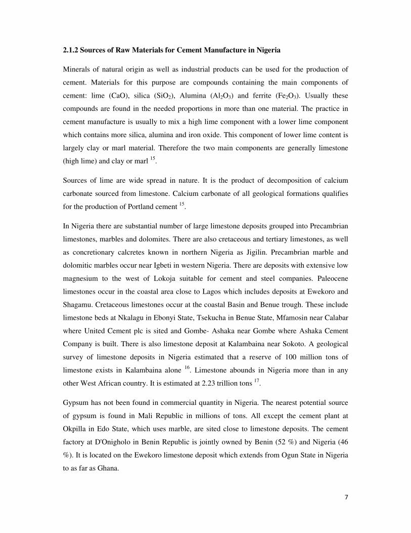
2.1.2 Sources of Raw Materials for Cement Manufacture in Nigeria
Minerals of natural origin as well as industrial products can be used for the production of
cement. Materials for this purpose are compounds containing the main components of
cement: lime (CaO), silica (SiO2), Alumina (Al2O3) and ferrite (Fe2O3). Usually these
compounds are found in the needed proportions in more than one material. The practice in
cement manufacture is usually to mix a high lime component with a lower lime component
which contains more silica, alumina and iron oxide. This component of lower lime content is
largely clay or marl material. Therefore the two main components are generally limestone
(high lime) and clay or marl 15
.
Sources of lime are wide spread in nature. It is the product of decomposition of calcium
carbonate sourced from limestone. Calcium carbonate of all geological formations qualifies
for the production of Portland cement 15
.
In Nigeria there are substantial number of large limestone deposits grouped into Precambrian
limestones, marbles and dolomites. There are also cretaceous and tertiary limestones, as well
as concretionary calcretes known in northern Nigeria as Jigilin. Precambrian marble and
dolomitic marbles occur near Igbeti in western Nigeria. There are deposits with extensive low
magnesium to the west of Lokoja suitable for cement and steel companies. Paleocene
limestones occur in the coastal area close to Lagos which includes deposits at Ewekoro and
Shagamu. Cretaceous limestones occur at the coastal Basin and Benue trough. These include
limestone beds at Nkalagu in Ebonyi State, Tsekucha in Benue State, Mfamosin near Calabar
where United Cement plc is sited and Gombe- Ashaka near Gombe where Ashaka Cement
Company is built. There is also limestone deposit at Kalambaina near Sokoto. A geological
survey of limestone deposits in Nigeria estimated that a reserve of 100 million tons of
limestone exists in Kalambaina alone 16
. Limestone abounds in Nigeria more than in any
other West African country. It is estimated at 2.23 trillion tons 17
.
Gypsum has not been found in commercial quantity in Nigeria. The nearest potential source
of gypsum is found in Mali Republic in millions of tons. All except the cement plant at
Okpilla in Edo State, which uses marble, are sited close to limestone deposits. The cement
factory at D'Onigholo in Benin Republic is jointly owned by Benin (52 %) and Nigeria (46
%). It is located on the Ewekoro limestone deposit which extends from Ogun State in Nigeria
to as far as Ghana.
8
Limestone at Mfamosing, near Calabar, is the largest and purest deposit in Nigeria. It is about
50 m thick at the quarry site. West of Calabar, another carbonate body occurs in the
subsurface that is 450 m thick. The Calabar flank is the main carbonate province in Nigeria,
with well developed tropical karst and caves. The Mfamosing limestone has over 97 percent
total carbonate 18
.
2.2 Chemical composition of Raw Materials for Cement Production
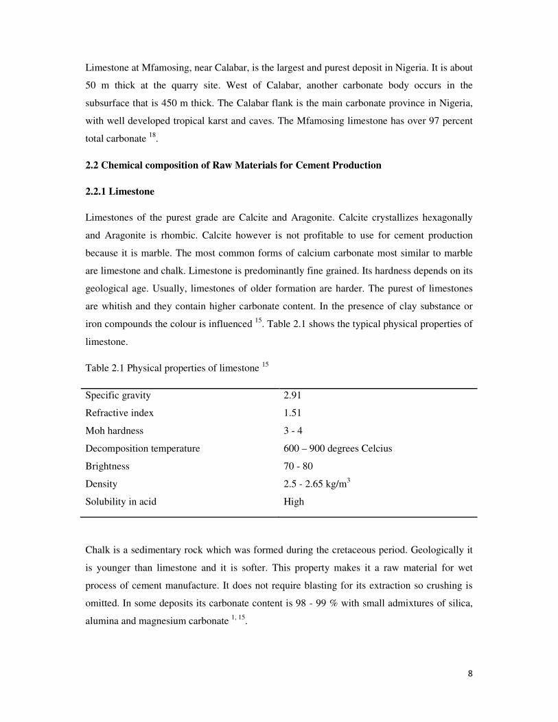
2.2.1 Limestone
Limestones of the purest grade are Calcite and Aragonite. Calcite crystallizes hexagonally
and Aragonite is rhombic. Calcite however is not profitable to use for cement production
because it is marble. The most common forms of calcium carbonate most similar to marble
are limestone and chalk. Limestone is predominantly fine grained. Its hardness depends on its
geological age. Usually, limestones of older formation are harder. The purest of limestones
are whitish and they contain higher carbonate content. In the presence of clay substance or
iron compounds the colour is influenced 15
. Table 2.1 shows the typical physical properties of
limestone.
Table 2.1 Physical properties of limestone 15
Specific gravity
Refractive index
Moh hardness
Decomposition temperature
Brightness
Density
Solubility in acid
2.91
1.51
3 - 4
600 – 900 degrees Celcius
70 - 80
2.5 - 2.65 kg/m3
High
Chalk is a sedimentary rock which was formed during the cretaceous period. Geologically it
is younger than limestone and it is softer. This property makes it a raw material for wet
process of cement manufacture. It does not require blasting for its extraction so crushing is
omitted. In some deposits its carbonate content is 98 - 99 % with small admixtures of silica,
alumina and magnesium carbonate 1, 15
.
9
Marl is a limestone that contains silica, clay and iron oxide. Marls are sedimentary rocks
generated by simultaneous sedimentation of calcium carbonate and clay substance. It is a
softer limestone due to its higher clay content. Its colour depends on the clay substance and
ranges from yellow to grayish black. They contain lime and clay component in an already
homogenized condition. This makes them suitable for cement manufacture 15, 19
.
Calcareous marl usually has a chemical composition like a carefully prehomogenized raw
mix of Portland cement. This type of limestone is used for making of natural cement.
However deposits of such raw materials are not common 1.
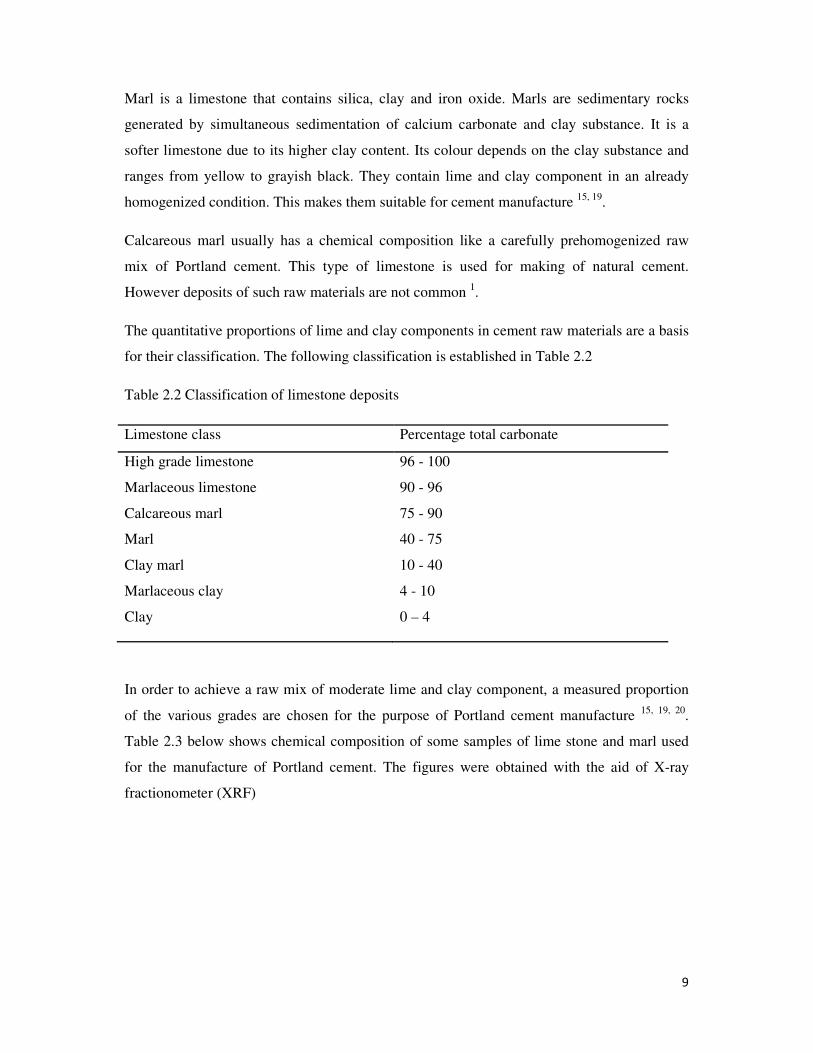
The quantitative proportions of lime and clay components in cement raw materials are a basis
for their classification. The following classification is established in Table 2.2
Table 2.2 Classification of limestone deposits
Limestone class Percentage total carbonate
High grade limestone
Marlaceous limestone
Calcareous marl
Marl
Clay marl
Marlaceous clay
Clay
96 - 100
90 - 96
75 - 90
40 - 75
10 - 40
4 - 10
0 – 4
In order to achieve a raw mix of moderate lime and clay component, a measured proportion
of the various grades are chosen for the purpose of Portland cement manufacture 15, 19, 20
.
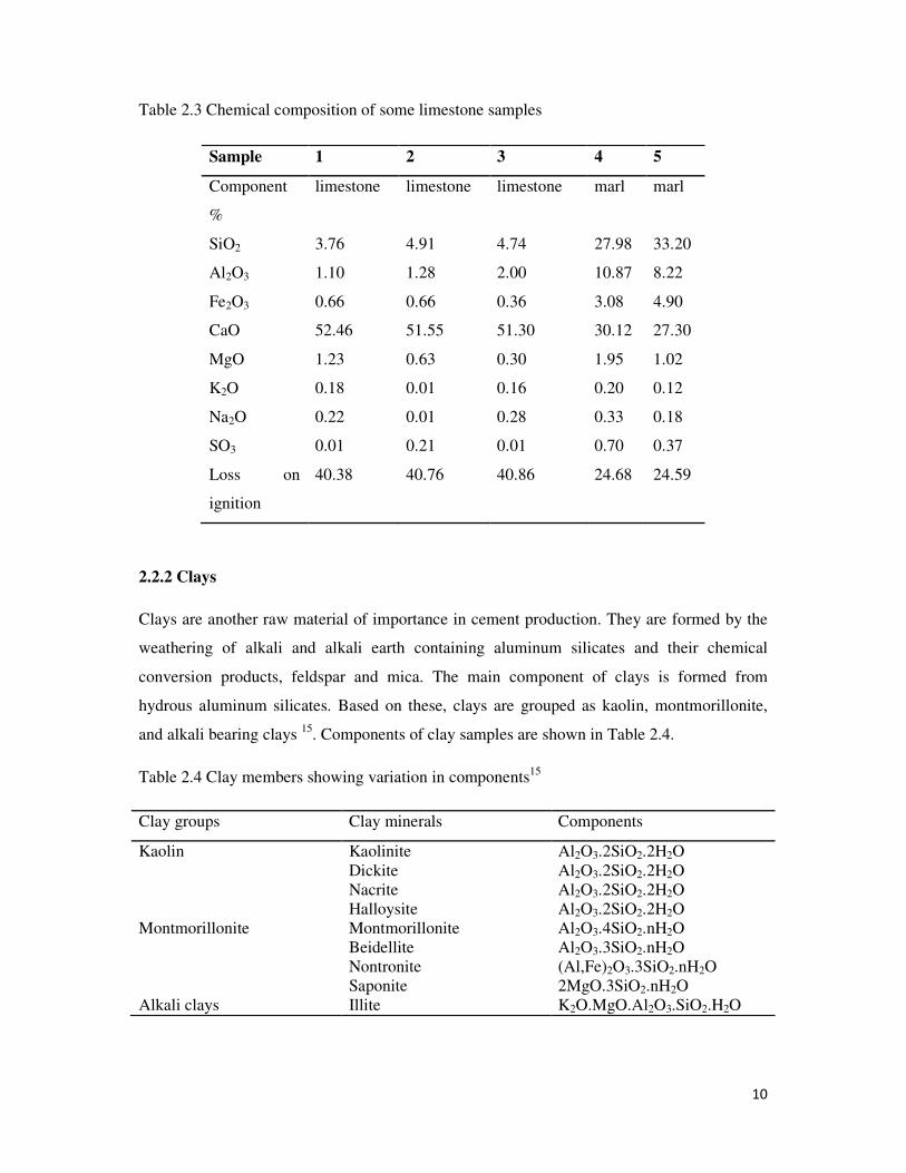
Table 2.3 below shows chemical composition of some samples of lime stone and marl used
for the manufacture of Portland cement. The figures were obtained with the aid of X-ray
fractionometer (XRF)
10
Table 2.3 Chemical composition of some limestone samples
2.2.2 Clays
Clays are another raw material of importance in cement production. They are formed by the
weathering of alkali and alkali earth containing aluminum silicates and their chemical
conversion products, feldspar and mica. The main component of clays is formed from
hydrous aluminum silicates. Based on these, clays are grouped as kaolin, montmorillonite,
and alkali bearing clays 15
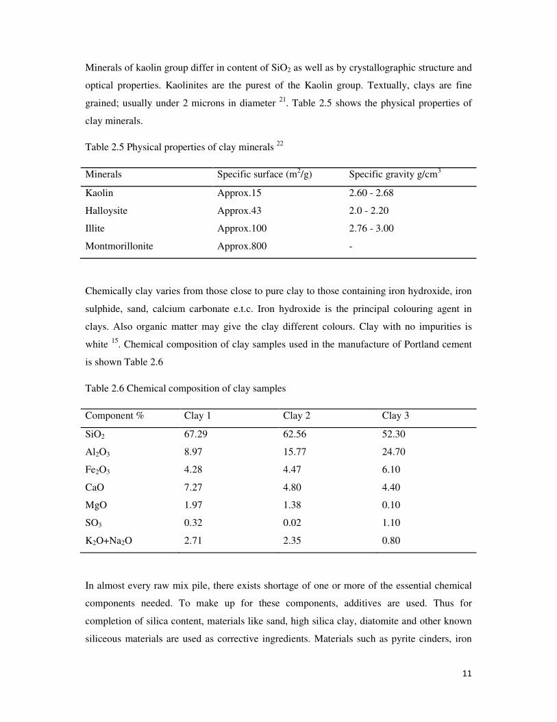
. Components of clay samples are shown in Table 2.4.
Table 2.4 Clay members showing variation in components15
Clay groups Clay minerals Components
Kaolin Kaolinite Al2O3.2SiO2.2H2O
Dickite Al2O3.2SiO2.2H2O
Nacrite Al2O3.2SiO2.2H2O
Halloysite Al2O3.2SiO2.2H2O
Montmorillonite Montmorillonite Al2O3.4SiO2.nH2O
Beidellite Al2O3.3SiO2.nH2O
Nontronite (Al,Fe)2O3.3SiO2.nH2O
Saponite 2MgO.3SiO2.nH2O
Alkali clays Illite K2O.MgO.Al2O3.SiO2.H2O
Sample 1 2 3 4 5
Component
%
limestone limestone limestone marl marl
SiO2 3.76 4.91 4.74 27.98 33.20
Al2O3 1.10 1.28 2.00 10.87 8.22
Fe2O3 0.66 0.66 0.36 3.08 4.90
CaO 52.46 51.55 51.30 30.12 27.30
MgO 1.23 0.63 0.30 1.95 1.02
K2O 0.18 0.01 0.16 0.20 0.12
Na2O 0.22 0.01 0.28 0.33 0.18
SO3 0.01 0.21 0.01 0.70 0.37
Loss on
ignition
40.38 40.76 40.86 24.68 24.59
11
Minerals of kaolin group differ in content of SiO2 as well as by crystallographic structure and
optical properties. Kaolinites are the purest of the Kaolin group. Textually, clays are fine
grained; usually under 2 microns in diameter 21
. Table 2.5 shows the physical properties of
clay minerals.
Table 2.5 Physical properties of clay minerals 22
Minerals Specific surface (m2/g) Specific gravity g/cm
3
Kaolin Approx.15 2.60 - 2.68
Halloysite Approx.43 2.0 - 2.20
Illite Approx.100 2.76 - 3.00
Montmorillonite Approx.800 -
Chemically clay varies from those close to pure clay to those containing iron hydroxide, iron
sulphide, sand, calcium carbonate e.t.c. Iron hydroxide is the principal colouring agent in
clays. Also organic matter may give the clay different colours. Clay with no impurities is
white 15
. Chemical composition of clay samples used in the manufacture of Portland cement
is shown Table 2.6
Table 2.6 Chemical composition of clay samples
Component % Clay 1 Clay 2 Clay 3
SiO2 67.29 62.56 52.30
Al2O3 8.97 15.77 24.70
Fe2O3 4.28 4.47 6.10
CaO 7.27 4.80 4.40
MgO 1.97 1.38 0.10
SO3 0.32 0.02 1.10
K2O+Na2O 2.71 2.35 0.80
In almost every raw mix pile, there exists shortage of one or more of the essential chemical
components needed. To make up for these components, additives are used. Thus for
completion of silica content, materials like sand, high silica clay, diatomite and other known
siliceous materials are used as corrective ingredients. Materials such as pyrite cinders, iron
12
ore, laterite are rich in iron oxide and are suitably used to correct iron deficiency 15, 21
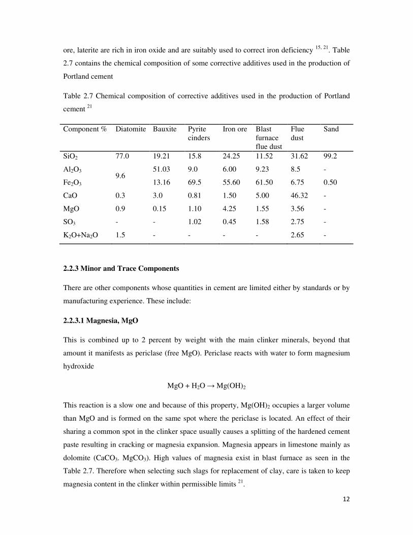
. Table
2.7 contains the chemical composition of some corrective additives used in the production of
Portland cement
Table 2.7 Chemical composition of corrective additives used in the production of Portland
cement 21
Component % Diatomite Bauxite Pyrite
cinders
Iron ore Blast
furnace
flue dust
Flue
dust
Sand
SiO2 77.0 19.21 15.8 24.25 11.52 31.62 99.2
Al2O3 9.6
51.03 9.0 6.00 9.23 8.5 -
Fe2O3 13.16 69.5 55.60 61.50 6.75 0.50
CaO 0.3 3.0 0.81 1.50 5.00 46.32 -
MgO 0.9 0.15 1.10 4.25 1.55 3.56 -
SO3 - - 1.02 0.45 1.58 2.75 -
K2O+Na2O 1.5 - - - - 2.65 -
2.2.3 Minor and Trace Components
There are other components whose quantities in cement are limited either by standards or by
manufacturing experience. These include:
2.2.3.1 Magnesia, MgO
This is combined up to 2 percent by weight with the main clinker minerals, beyond that
amount it manifests as periclase (free MgO). Periclase reacts with water to form magnesium
hydroxide
MgO + H2O → Mg(OH)2
This reaction is a slow one and because of this property, Mg(OH)2 occupies a larger volume
than MgO and is formed on the same spot where the periclase is located. An effect of their
sharing a common spot in the clinker space usually causes a splitting of the hardened cement
paste resulting in cracking or magnesia expansion. Magnesia appears in limestone mainly as
dolomite (CaCO3. MgCO3). High values of magnesia exist in blast furnace as seen in the
Table 2.7. Therefore when selecting such slags for replacement of clay, care is taken to keep
magnesia content in the clinker within permissible limits 21
.
13
2.2.3.2 Alkalis
Oxides of potassium and sodium originate from clay and marl, where these compounds are
present in feldspar, mica and illite particles. In Europe potassium oxide is dominant. In other
areas like in the United States of America sodium oxide dominates. To avoid alkali expansion
in cements low alkali materials are used. From experience, Total alkalis (K2O + Na2O) are
not allowed to exceed 0.6 percent in clinker 21
.
2.2.3.3 Sulphur
Sulphur appears predominantly as sulphide in pyrites and marcasite in almost all cement raw
materials. An investigation of more than 90 German limestone deposits showed a total
sulphhur content of maximum 0.16 percent and an examination of 67 clay samples showed an
average of 0.22 percent sulphur. The presence of alkalis in excess of amount which is already
combined with sulphur contained in the raw mix allows the use of fuels rich in sulphur like
low pour fuel oil (LPFO) without emitting substantial amount of SO2 when the raw material
undergoes thermal treatment in the kiln. The alkali sulphate combined by the clinker is of
advantage for the early strength development of cement 21
.
2.2.3.4 Phosphorus
The phosphorus content of commonly used cement raw materials is very low. In Germany for
instance, the phosphorus pentoxide (P2O5) in clinker is within limits of 0.05 and 0.25 percent
21.
Certain industrial waste products containing one or more of the four basic oxides may be
regarded as raw materials. For example, blast furnace slag from steel works 15, 20
. In fact
using industrial by products to replace natural raw material is key element in achieving
sustainable economic growth.
Gypsum is also an essential raw material used in the production of cement. About 5 percent
added to burned cement clinker during grinding controls setting time of the cement. Gypsum
contains natural anhydrite such as calcium sulphate as dihydrate, calcium sulphate anhydrate
and calcium carbonate or clay as impurities 20
.
Gypsiferous shales are found in the upper cretaceous Dukarnaje formation and the Paleocene
Dange formation in Sokoto State of Nigeria. The abundance of gypsiferous shales at these

14
locations is estimated at 1.46 million tons. Other deposits are found in Nafada, Gombe State,
at Fika in Yobe State and at Guyuk, Adamawa State 23
.
2.3 Types of Portland cement
Different types of Portland cement with different physical and chemical properties are
manufactured for specific purposes. The American Society for Testing and Materials (ASTM
C150) recognizes five types of Portland cement 20
:
2.3.1 Type 1
This is ordinary Portland cement (OPC) which is made of clinker and gypsum alone. It is the
best cement because of its strength development. It is mostly the widely used general
purpose. It is used where cement or concrete is not subject normal to specific exposures, such
as sulphate attack from soil or water, or to a temperature rise due to heat generated by
hydration. Its uses include pavements and sidewalks, reinforced concrete buildings, bridges,
railway structures, tanks, reservoirs, culverts, sewers, water pipes and masonry works. All
Nigerian cement companies produce this type of cement 20, 24
.
2.3.2 Type 2
This is also general purpose Portland cement. It differs from Type 1 due to the fact that
additives (other than gypsum) are included in its production. Examples of such additives
include limestone and pozollan. These additives do not alter the quality markedly, only that a
little of the cement portion is reduced. It is used where precaution against moderate sulphate
is important, as in drainage structures, where sulphate concentrations in ground waters are
higher than normal, but not severe. It minimizes temperature rise when concrete is placed in
warm weather because it generates less heat at slower rate than Type 1. With its moderate
heat of hydration, Type 2 cements can be used in structures of considerable mass such as
abutments and piers, and heavy retaining walls. Type 2 cements are sometimes referred to as
blended cements 20, 25
.
2.3.3 Type 3
This is ordinary Portland cements containing higher lime to silica ratio than Type 1 produced
to achieve rapid hardening. They contain higher tricalcium silicate which confers higher early
strength. Type 3 cements are used in concrete works for economic advantages to achieve
quick removal of form work or rapid turn- around of precast concrete units in a mould. Roads
15
constructed using this type of cement are put to use earlier than those constructed using
Type1 cement 20
.
2.3.4 Type 4
These are ordinary Portland cements produced to achieve lower heat due to lower tricalcium
silicate and tricalcium aluminate content. These cause a lower heat of hydration. The
tricalcium aluminate is lowered with addition of iron oxide which consequently increases
tetracalcium aluminoferrite. This is a condition that reduces heat evolution. This class of
cements is intended for mass structures like dam works when temperature rise is great on
continuous pour of cement. In such works, if temperature is not minimized, it will cause large
cracks in the structure, rendering it weak 20
.
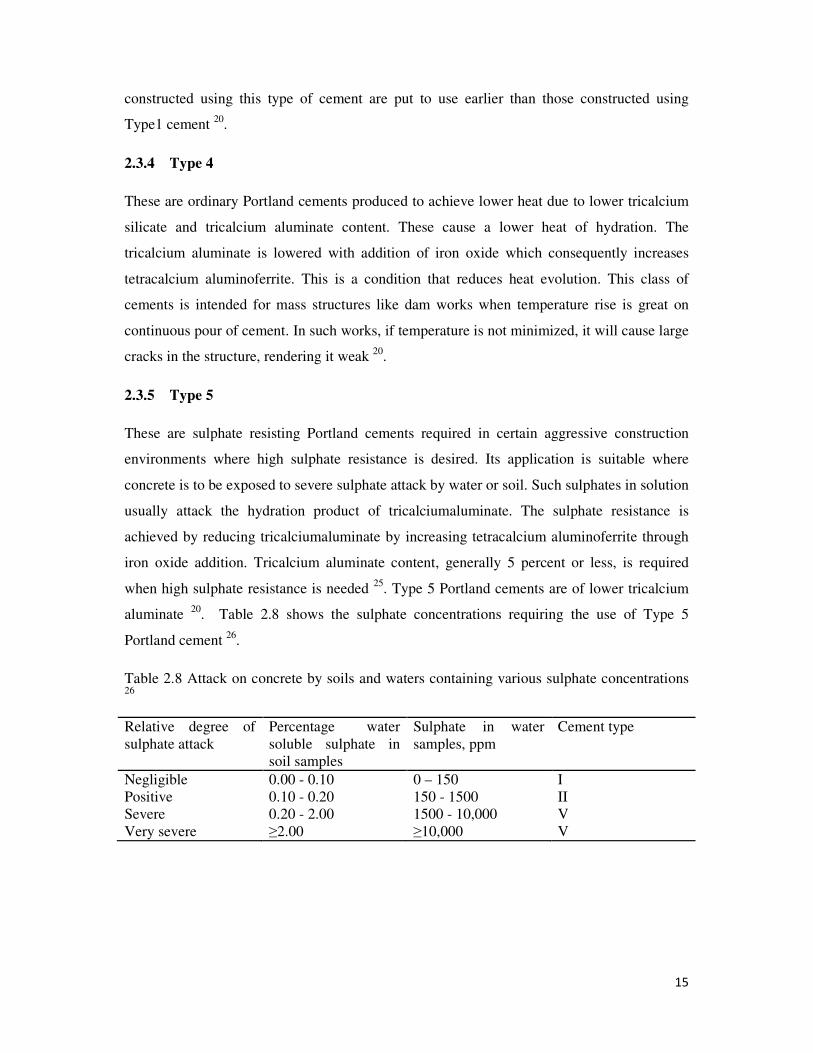
2.3.5 Type 5
These are sulphate resisting Portland cements required in certain aggressive construction
environments where high sulphate resistance is desired. Its application is suitable where
concrete is to be exposed to severe sulphate attack by water or soil. Such sulphates in solution
usually attack the hydration product of tricalciumaluminate. The sulphate resistance is
achieved by reducing tricalciumaluminate by increasing tetracalcium aluminoferrite through
iron oxide addition. Tricalcium aluminate content, generally 5 percent or less, is required
when high sulphate resistance is needed 25
. Type 5 Portland cements are of lower tricalcium
aluminate 20
. Table 2.8 shows the sulphate concentrations requiring the use of Type 5
Portland cement 26
.
Table 2.8 Attack on concrete by soils and waters containing various sulphate concentrations 26
Relative degree of
sulphate attack
Percentage water
soluble sulphate in
soil samples
Sulphate in water
samples, ppm
Cement type
Negligible 0.00 - 0.10 0 – 150 I
Positive 0.10 - 0.20 150 - 1500 II
Severe 0.20 - 2.00 1500 - 10,000 V
Very severe ≥2.00 ≥10,000 V
16
2.3.6 Other Types of Cements
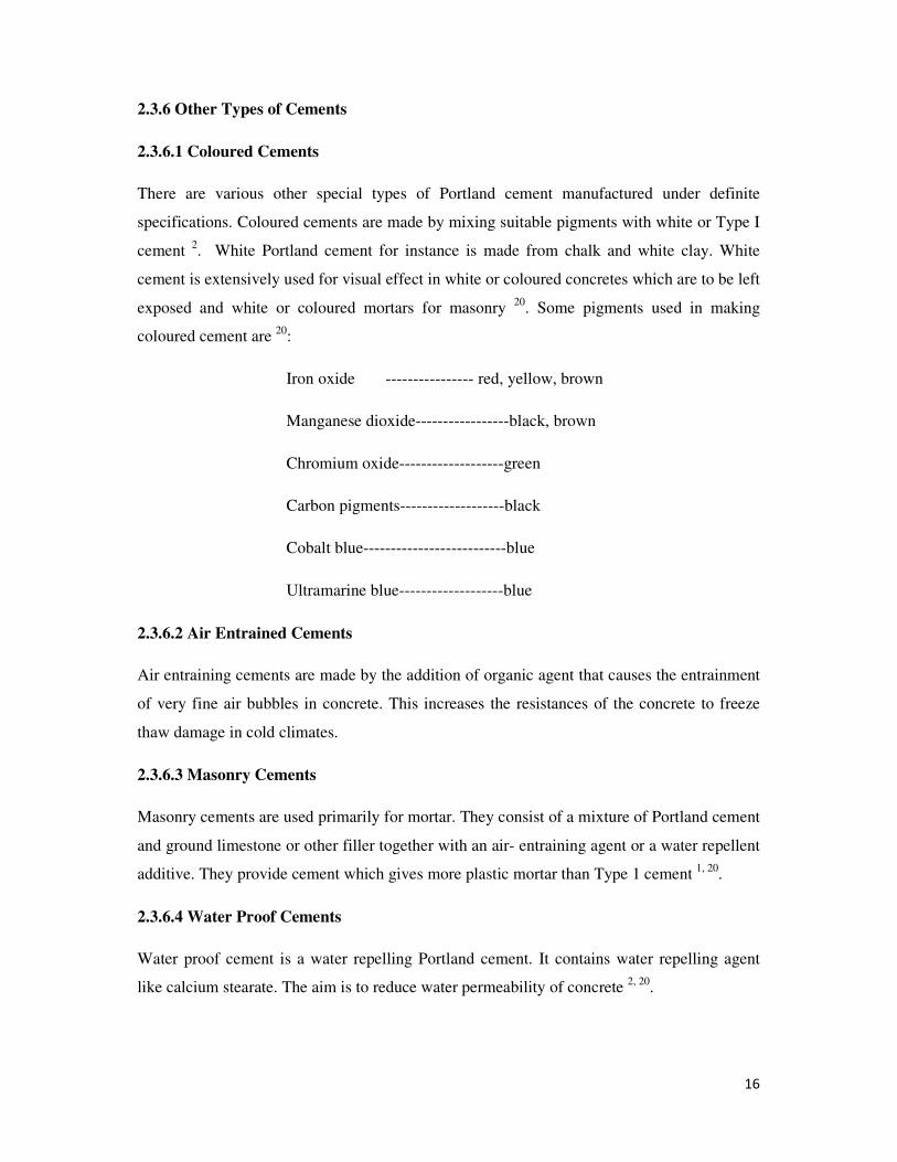
2.3.6.1 Coloured Cements
There are various other special types of Portland cement manufactured under definite
specifications. Coloured cements are made by mixing suitable pigments with white or Type I
cement 2. White Portland cement for instance is made from chalk and white clay. White
cement is extensively used for visual effect in white or coloured concretes which are to be left
exposed and white or coloured mortars for masonry 20
. Some pigments used in making
coloured cement are 20
:
Iron oxide ---------------- red, yellow, brown
Manganese dioxide-----------------black, brown
Chromium oxide-------------------green
Carbon pigments-------------------black
Cobalt blue--------------------------blue
Ultramarine blue-------------------blue
2.3.6.2 Air Entrained Cements
Air entraining cements are made by the addition of organic agent that causes the entrainment
of very fine air bubbles in concrete. This increases the resistances of the concrete to freeze
thaw damage in cold climates.
2.3.6.3 Masonry Cements
Masonry cements are used primarily for mortar. They consist of a mixture of Portland cement
and ground limestone or other filler together with an air- entraining agent or a water repellent
additive. They provide cement which gives more plastic mortar than Type 1 cement 1, 20
.
2.3.6.4 Water Proof Cements
Water proof cement is a water repelling Portland cement. It contains water repelling agent
like calcium stearate. The aim is to reduce water permeability of concrete 2, 20
.
17
2.3.6.5 Hydrophobic Cements
Hydrophobic cement is obtained by grinding Portland cement clinker with film forming
substance such oleic acid in order to reduce the rate of deterioration when the cement is
stored under unfavourable conditions or transported along distances20
.
2.3.6.6 Oil Well Cements
Oil well cements are used for cementing work in the drilling of oil wells where they are
subject to high temperatures and pressures. They usually consist of type1 cement made
coarser than usual mixed with organic retarders such as starch and sugar to prevent rapid
setting 15, 20
.
2.3.6.7 Slag Cements
The granulated slag made by rapid chilling of suitable molten slags from blast furnaces is
another group of constructional cements. Slag cement is a mixture of Type 1 cement and
granulated slag containing up to 65 percent slag. Properties of these slag cements are similar
to those of Portland cement but they have lower lime content and higher silica and alumina
content. Those with the higher slag content have increased resistance to chemical attack 2.
The super sulphated cement is another type of slag cement. This type contains lesser lime
than blast furnace cement. It contains up to 15 percent hard burned gypsum or anhydrite
(natural anhydrous calcium sulphate). The strength properties are similar to those of Portland
cement but it has an increased resistance to many forms of chemical attack 2. Slag based
cements can be used for general concrete construction, having the advantage of possible low
cost since their major raw material is a bye product of iron and steel industry. In addition,
such cements can be used in projects where low heat of hydration is essential 20
.
2.3.6.8 High Alumina Cements
High alumina cements are manufactured by fusing at 1500 to 1600 oC a mixture of limestone
and bauxite which contains iron oxide, silica, magnesia and other impurities in an electric
furnace or in a rotary kiln. They have several properties such as high early strength which can
compare to that at 28 days in Portland cement within 24 to 48 hours, good refractoriness and
good resistance to sulphate attacks from sea and sulphate bearing water. However, their
limitation is that higher temperatures tend to reduce their strength in the presence of moisture.
High alumina cements are used where high early strength is required and moderate
18
temperatures are desired like in refractory linings for furnaces. A white form of the cement
has excellent refractory properties 2, 20
.
2.4 Composition of Portland Cement
Ordinary Portland cement consists of clinker and gypsum ground together. Clinker consists
essentially of a mixture of four crystalline compounds of calcium. Two have silica, one has
alumina and one has both alumina and ferric oxide. Thus clinker has constituents, namely;
lime, silica, alumina and ferric oxide. There are also several minor constituents, including
alkalis, magnesia and sulphur, which together amount to between 2 and 6 % by weight. In an
abbreviated notation, differing from the normal atomic symbols, these compounds are
assigned the following symbols: C3S (tricalcium silicate), C2S (dicalcium silicate), C3A
(tricalcium aluminate) and C4AF (tetracalcium aluminoferrite). C stands for lime, S stands for
silica, A stands for alumina and F for ferrite. Small amounts of uncombined lime and
magnesia also are present, along with alkalis and minor amounts of other elements.
The most important hydraulic constituents are C2S and C3S. C3S hydrates with moderate of
heat of hydration; the rate of hydration is controlled by the rate of diffusion of water through
the layer of calcium silicate hydrate forming on each particle of hydrating C3S. Thus,
hydration slows as thickness of hydrate layer increases. This hydration reaction contributes to
early strength of concrete within a week and beyond.
C2S hydrates more slowly and contributes more to late strength of concrete at 28 days and
beyond in conjunction with residual unhydrated C3S.
C3A hydrates very rapidly and violently as well. This is responsible for very quick setting but
contributes little to strength. This explains the quick setting of high alumina cements like the
early Roman cements. C3A and C4AF contribute little to strength and structure of concretes.
2.5 Estimation of Clinker Composition
The composition of clinker minerals was calculated from chemical analysis by Bogue 27
. This
method however, could only estimate the quantity or bulk of the minerals, leaving out the
actual mineralogical composition. Such results obtained by this method were known as
potential clinker composition. The ASTM cement standards of the United States of America
is based on Bogue’s calculation 28
. Bogue estimated that C3S contains 73.69 % CaO and
19
26.31% SiO2, C2S contains 65.12 % CaO and 34.88 % SiO2. In C3A is contained 62.27 %
CaO and 37.73 % SiO2 while C4AF 46.16 % CaO, 20.98 % Al2O3 and 32.86 % Fe2O3.
Bogue assumed that in every mixture of the four compounds, CaO was the sum of all lime
percentages as shown
CaO = 0.7369 C3S+ 0.6512 C2S+ 0.6227 C3A+0.4616 C4AF 1
With similar analogy for the other oxides and solving for the potential clinker compositions
C3S= 4.071 CaO- 7.600 SiO2-6.718 Al2O3- 1.430 Fe2O3 2
C2S= 8.602 SiO2 + 5.068 Al2O3 -3.071 CaO+ 1.078 Fe2O3 3
C3A= 2.650 Al2O3+ 1.692 Fe2O3 4
C4AF= 3.043 Fe2O3 5
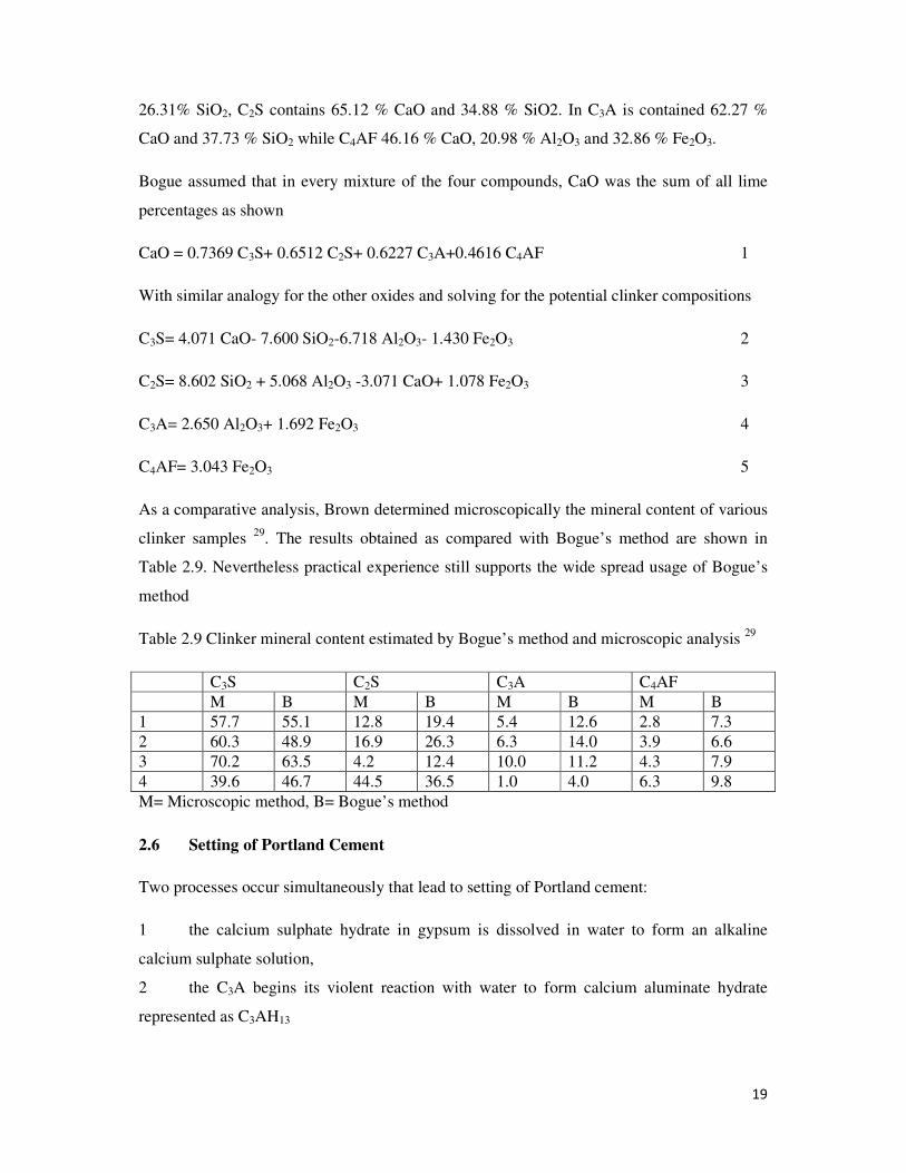
As a comparative analysis, Brown determined microscopically the mineral content of various
clinker samples 29
. The results obtained as compared with Bogue’s method are shown in
Table 2.9. Nevertheless practical experience still supports the wide spread usage of Bogue’s
method
Table 2.9 Clinker mineral content estimated by Bogue’s method and microscopic analysis 29
C3S C2S C3A C4AF
M B M B M B M B
1 57.7 55.1 12.8 19.4 5.4 12.6 2.8 7.3
2 60.3 48.9 16.9 26.3 6.3 14.0 3.9 6.6
3 70.2 63.5 4.2 12.4 10.0 11.2 4.3 7.9
4 39.6 46.7 44.5 36.5 1.0 4.0 6.3 9.8
M= Microscopic method, B= Bogue’s method
2.6 Setting of Portland Cement
Two processes occur simultaneously that lead to setting of Portland cement:
1 the calcium sulphate hydrate in gypsum is dissolved in water to form an alkaline
calcium sulphate solution,
2 the C3A begins its violent reaction with water to form calcium aluminate hydrate
represented as C3AH13
20
During these processes an intermediate, ettringite (calcium aluminate trisulphate hydrate) is
formed. As the pH of the system increases towards alkalinity, ettringite becomes insoluble,
and gets deposited on the surface of the hydrating C3A, providing a layer slowing the rapid
hydration. Since the rate of reaction is determined by the rate of diffusion of water through
the ettringite layer, rapid setting is controlled 1, 15
.
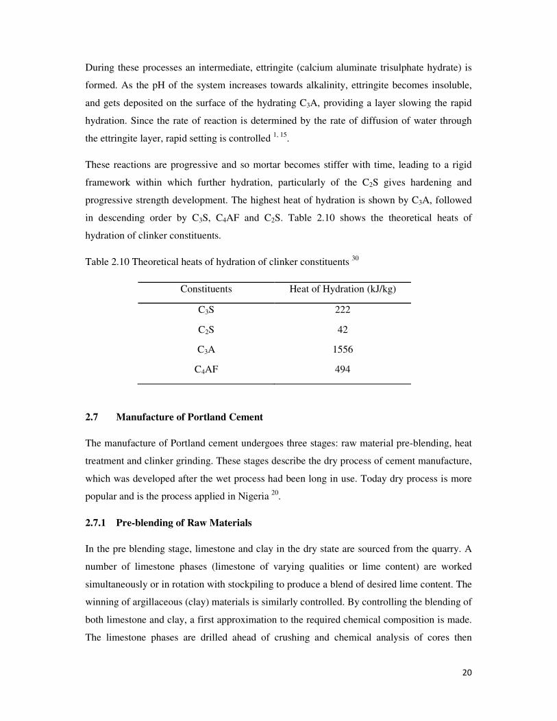
These reactions are progressive and so mortar becomes stiffer with time, leading to a rigid
framework within which further hydration, particularly of the C2S gives hardening and
progressive strength development. The highest heat of hydration is shown by C3A, followed
in descending order by C3S, C4AF and C2S. Table 2.10 shows the theoretical heats of
hydration of clinker constituents.
Table 2.10 Theoretical heats of hydration of clinker constituents 30
Constituents Heat of Hydration (kJ/kg)
C3S 222
C2S 42
C3A 1556
C4AF 494
2.7 Manufacture of Portland Cement
The manufacture of Portland cement undergoes three stages: raw material pre-blending, heat
treatment and clinker grinding. These stages describe the dry process of cement manufacture,
which was developed after the wet process had been long in use. Today dry process is more
popular and is the process applied in Nigeria 20
.
2.7.1 Pre-blending of Raw Materials
In the pre blending stage, limestone and clay in the dry state are sourced from the quarry. A
number of limestone phases (limestone of varying qualities or lime content) are worked
simultaneously or in rotation with stockpiling to produce a blend of desired lime content. The
winning of argillaceous (clay) materials is similarly controlled. By controlling the blending of
both limestone and clay, a first approximation to the required chemical composition is made.
The limestone phases are drilled ahead of crushing and chemical analysis of cores then
21
followed by blending proportion. This raw material (raw mix) preparation is done
arithmetically. The purpose of calculating the composition of the raw mix is to determine the
quantitative proportions of the raw components in order to give the clinker the desired
mineralogical composition. Methods of calculation include: allegation alternate method,
hydraulic module and lime saturation factor.
The most used is the allegation alternate method which shows the ratio of limestone to clay to
be used. In this case, lime is the only component under consideration. Hydraulic module is
applied when more than one component is considered with the hydraulic module selected for
the clinker. This means that the modules of both raw material and clinker are equated since it
is expected that the raw material must share module with clinker to achieve desired clinker
quality. Thus
HM= C/ S+A+F for clinker ………6
HM= C rm/ Srm +A rm+ Frm for raw mix ………7
Where HM is hydraulic module. C, S, A and F are symbols for lime, silica, alumina then
Ferrite.
Since HM for clinker and raw mix are equal;
HM= C/ S+A+F= C rm/ Srm +A rm+ Frm ………8
This method assumes that x parts of the first raw material are apportioned to one part of the
second raw material. Under this assumption, the quantities of the particular raw material
components can be calculated as follows:
Crm=xC1+C2/x+1 ………9
Srm= xS1+S2/ x+1 ………10
Arm=xA1+A2/x+1 ..……11
Frm= xF1+F2/x+1 ………12
Inserting the values of Crm, Srm, Frm and Arm into the hydraulic module formula, we get;
HM= (XC1+C2/X+1)/ (XS1+S2/X+1) + (XA1+A2/X+1) + (XF1+F2/X+1) …….. 13
22
The basis for calculation is the chemical composition of the raw materials. Since the oxides
are known, the only remaining unknown is X. After transforming the equation the value of X
becomes
X=HM (S2+A2+F2)-C2/C1-HM (S1+A1+F1) ………14
This means X parts of limestone with one part of another component is required to achieve
clinker of a desired HM.
The crushed material is laid in thin layers on long stockpiles. As crushing goes on samples
are taken and analysed to determine adherence to planned stockpiling of the raw material.
This reduces chemical variation during reclamation to a minimum for minimum usage of
corrective additives. The stockpiled raw mix is recovered and ground to fine powder to be fed
into the kiln tube as kiln feed.
2.7.2 Heat Treatment
Reactions and temperatures in rotary kilns are strictly checked in clinkerization. The basic
steps are (i) evaporating off any water,(ii) decarbonization of calcium carbonate at
temperatures up to 1000 0C, (iii) heating the decarbonated material long enough for cement
compounds to form between 1300 – 1500 oC, according to its composition and fineness and
(iv) cooling the resulting clinker.
Through a temperature profile from 100 0C to above 1280
0C different reactions take place as
follows:
100 0C evapouration of free water which is endothermic
500 0C and above endothermic dehydroxylation of clay minerals
900 0C and above exothermic crystallization of products of clay and decomposition of
calcium carbonate.
CaCO3 → CaO + CO2
CaO + Al2O3 → CaO.Al2O3
900-1200 0C lime reacts with aluminosilicates which are the dehydroxylation products of
clay. This is an exothermic reaction.
1250 -1280 0C this is the burning zone in the temperature profile. At
formation takes place and rates of reaction increase
phase increases to a maximum at the highest temperature. T
through crystallization from the liquid phase. C
2CaO.SiO
Above 1280 0C the cement compounds are formed signifying completion of
clinkerization. Below 12800C is the cool zone where C
3CaO.Al2O
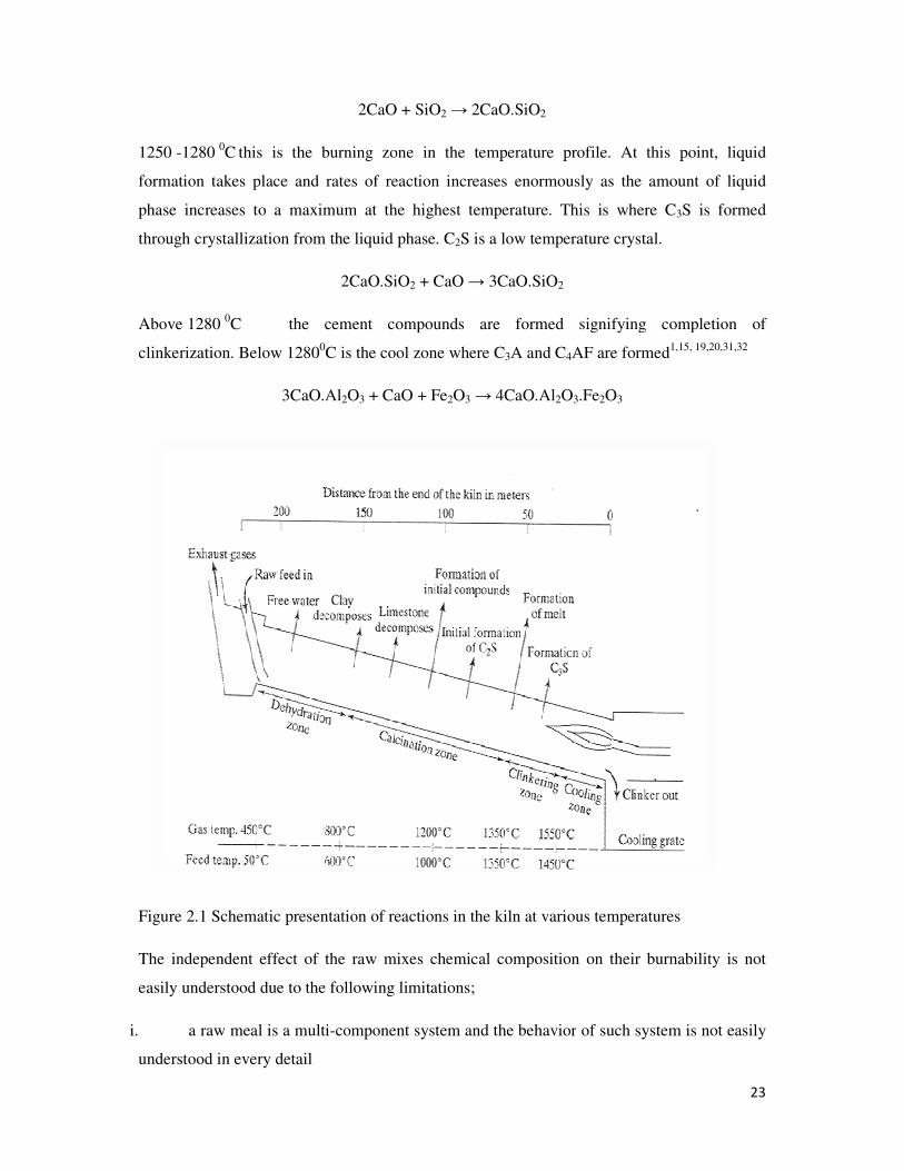
Figure 2.1 Schematic presentation of reactions in the kiln at various temperatures
The independent effect of the raw mixes
easily understood due to the following limitations;
i. a raw meal is a multi-component system and the behavior
understood in every detail
2CaO + SiO2 → 2CaO.SiO2
this is the burning zone in the temperature profile. At this point
formation takes place and rates of reaction increases enormously as the amount of liquid
ximum at the highest temperature. This is where C
through crystallization from the liquid phase. C2S is a low temperature crystal.
2CaO.SiO2 + CaO → 3CaO.SiO2
the cement compounds are formed signifying completion of
C is the cool zone where C3A and C4AF are formed1
O3 + CaO + Fe2O3 → 4CaO.Al2O3.Fe2O3
tation of reactions in the kiln at various temperatures
The independent effect of the raw mixes chemical composition on their burnability is not
easily understood due to the following limitations;
component system and the behavior of such system is not easily
23
this point, liquid
the amount of liquid
his is where C3S is formed
the cement compounds are formed signifying completion of
1,15, 19,20,31,32
tation of reactions in the kiln at various temperatures
chemical composition on their burnability is not
such system is not easily
24
ii. the major components, mainly oxides, contain some other minerals in minor
quantities and all differ in their reactivity
iii. the mineralizing effect of some of the minor constituents cannot be predicted with
certainty in such a complex system 33
The oxides by which a clinker composition is represented usually come from the natural raw
material, made up of various compounds. For instance lime, CaO, in a raw mix is the sum
total of CaO coming from all lime bearing compounds present in the mix. Thus lime may
come from calcite, dolomite, ankerite, gypsum, phosphates, feldspars and clay compounds.
Similarly, it is estimated that half of silica in the raw mix comes from free quartz and the rest
from clay minerals like kaolinite, montmorillomite, hydromica etc which also simultaneously
supply the required alumina. Therefore, the reactivity of the raw material is determined by the
reactions of the constituent minerals which are controlled by temperature profile. The
reactions proceed over a wide range of temperature, depending on the intrinsic characteristics
of the raw materials, and any breach of concurrence of these steps leads to disturbance of the
reaction kinetics. The stages of reaction depend on the mineral form and micro- structural
features of the materials.
At high temperature, calcium carbonate decomposes in accordance with the equation
CaCO3 → CaO + CO2 -42.52 Kcal
The dissociation temperature of pure calcium carbonate is 898 oC, and it is reported to vary
from 812 - 928 oC depending on grain size and solid solubility of CaO in CaCO3
37, 38.
Complete dissociation and release of free CaO are known to start from 550 oC and continue
up to as high as 1000 - 1100 oC. Such variations in the dissociation of carbonates are due to
i. forms of carbonate present,
ii. associated minerals, and
iii. degree of crystallinity and grain size of the carbonates.
As a result of these factors,
1 the dissociation of carbonates and reactivity of CaO decrease in the order
Calcite → Dolomite → Ankerite
25
Therefore if ankerite is present in the limestone used in making a clinker, it is expected to
release lime at relatively lower temperature and if there is no assimilation of this lime due to
non availability of other reactive components, the lime crystals tend to be more ordered with
rise in temperature and lose their reactive state.
It is observed that lime crystals obtained from dissociation of dolomite are 1.5 - 2 times
smaller than those obtained from calcite, thus providing greater surface area, which results in
faster reaction 33, 36
.
2 the effect of the associated minerals and oxides lower the decomposition temperature
of limestone. Thus the dissociation pressure of calcite is increased by oxides like SiO2, Al2O3
and Fe2O3. Therefore in the presence of such impurities, the dissociation of calcite starts at
about 550 oC, but the dissociation rate is controlled by the formation rate of compounds with
other oxides until the actual dissociation temperature of 898 oC is reached. At this point it is
observed that the rate of release of free lime from the calcite is more than its assimilation rate.
It is also observed that the presence of fluorides leads to higher rates of calcium carbonate
dissociation temperature and that phosphates also have catalytic properties 33, 35
. The catalytic
action on the dissociation of carbonates is accompanied by intensive mineralization of lime
crystals which becomes less reactive with acidic oxides 33
.
3 the rate of dissociation and the reaction temperature of calcite have a direct
correlation with grain size. The decomposition of calcium carbonate starts with the formation
of pseudo morphs of two dimensional lime crystals after calcium carbonate crystals. Only
after some time do three dimensional nuclei of CaO crystals appear. The coarser the crystals
and more perfect their structure the longer the time between the two and three dimensional
crystals formation. This period is induction period. This implies that there are two stages of
carbonate decomposition;
• kinetic stage in which the rate of which is determined by the energy of formation and
concentration of CaO nuclei
• Diffusive stage, in which the rate depends on the thickness of penetrable shells on
calcium carbonate particles as well as on the diffusion rate of carbondioxide through it.
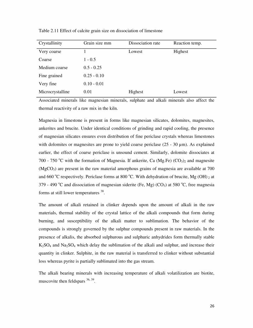
The decomposition characteristics of limestone are affected by the grain size and
crystallinity, particularly in the second stage 33, 34, 37
. Table 2.11 shows the relationship
between calcite grain size and decomposition of limestone.
26
Table 2.11 Effect of calcite grain size on dissociation of limestone
Crystallinity Grain size mm Dissociation rate Reaction temp.
Very coarse 1 Lowest Highest
Coarse 1 - 0.5
Medium coarse 0.5 - 0.25
Fine grained 0.25 - 0.10
Very fine 0.10 - 0.01
Microcrystalline 0.01 Highest Lowest
Associated minerals like magnesian minerals, sulphate and alkali minerals also affect the
thermal reactivity of a raw mix in the kiln.
Magnesia in limestone is present in forms like magnesian silicates, dolomites, magnesites,
ankerites and brucite. Under identical conditions of grinding and rapid cooling, the presence
of magnesian silicates ensures even distribution of fine periclase crystals whereas limestones
with dolomites or magnesites are prone to yield coarse periclase (25 - 30 µm). As explained
earlier, the effect of coarse periclase is unsound cement. Similarly, dolomite dissociates at
700 - 750 oC with the formation of Magnesia. If ankerite, Ca (Mg.Fe) (CO3)2 and magnesite
(MgCO3) are present in the raw material amorphous grains of magnesia are available at 700
and 660 oC respectively. Periclase forms at 800
oC. With dehydration of brucite, Mg (OH) 2 at
379 - 490 oC and dissociation of magnesian siderite (Fe, Mg) (CO3) at 580
oC, free magnesia
forms at still lower temperatures 38
.
The amount of alkali retained in clinker depends upon the amount of alkali in the raw
materials, thermal stability of the crystal lattice of the alkali compounds that form during
burning, and susceptibility of the alkali matter to sublimation. The behavior of the
compounds is strongly governed by the sulphur compounds present in raw materials. In the
presence of alkalis, the absorbed sulphurous and sulphuric anhydrides form thermally stable
K2SO4 and Na2SO4 which delay the sublimation of the alkali and sulphur, and increase their
quantity in clinker. Sulphite, in the raw material is transferred to clinker without substantial
loss whereas pyrite is partially sublimated into the gas stream.
The alkali bearing minerals with increasing temperature of alkali volatilization are biotite,
muscovite then feldspars 36, 39
.
27
The diffusion rate of lime CaO in the lattice of silica is four to five times higher than that of
silica in CaO lattice 37
. It therefore means that silica bearing materials are the determining
factor in the reactivity of raw mixes. The reactivity of different forms of silica with CaO
increases in the order;
Quartz → chalcedony → opal → alpha-cristobalite → trydymite → silica from feldspars →
silica from amphiboles, mica and clay minerals → silica from slag
Quartz crystals under the action of catalysts like Na+, K
+, Fe
3+, Fe
2+, F
- and Cl
- even at 800 -
1000 oC are transformed into fine reticulate cristobalite. The cristobalite is of a higher
reactivity due to its low density and defect state caused by the loss of O2-
and formation of the
same amount of silicon monoxide 33
. The silica in free form and of least reactivity determine
the rate of mineral formation, therefore silica in amorphous and hydrosilicates is preferable to
silica in other forms.
Clays show similar pattern of changes with temperature; dehydration, dehydroxylation,
breakdown of crystal structures producing reactive amorphous metaproducts and formation of
new phases. In cement making, advantage is taken of clays reactive state before stable phases
are formed. The water obtained from removal of hydroxyl group of clays has favourable
effect on the dissociation of calcium carbonate 38
. Due to variation in composition of clay
minerals, as well as the simultaneous presence of several clay minerals in one clay,
correlation of clay mineral forms with their burnability and reactivity is difficult. The
following clay minerals have a decreasing order of reactivity:
(Montmorillonite, halloysite) → (kaolinite, nontronite, biotite) → (pyrophyllite, muscovite,
vermiculite)
Some observe increased reactivity of raw mixes with increased kaolinite than other clays. The
reason advanced for this observation is that the products of the breakdown of the kaolinite
structure are highly reactive with calcium carbonate 38
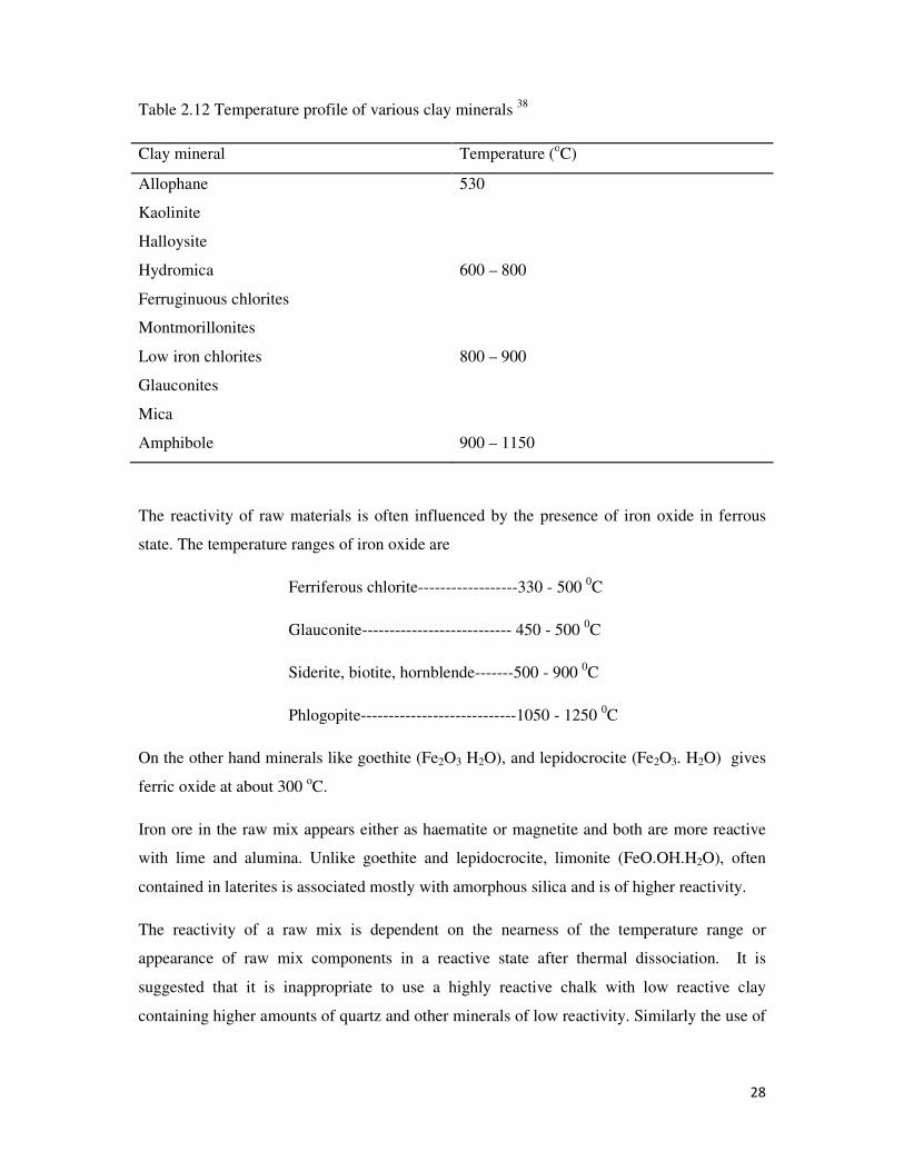
. Table 2.12 shows the reactivity of
different clays at corresponding temperatures.
28
Table 2.12 Temperature profile of various clay minerals 38
Clay mineral Temperature (oC)
Allophane 530
Kaolinite
Halloysite
Hydromica 600 – 800
Ferruginuous chlorites
Montmorillonites
Low iron chlorites
Glauconites
800 – 900
Mica
Amphibole 900 – 1150
The reactivity of raw materials is often influenced by the presence of iron oxide in ferrous
state. The temperature ranges of iron oxide are
Ferriferous chlorite------------------330 - 500 0C
Glauconite--------------------------- 450 - 500 0C
Siderite, biotite, hornblende-------500 - 900 0C
Phlogopite----------------------------1050 - 1250 0C
On the other hand minerals like goethite (Fe2O3 H2O), and lepidocrocite (Fe2O3. H2O) gives
ferric oxide at about 300 oC.
Iron ore in the raw mix appears either as haematite or magnetite and both are more reactive
with lime and alumina. Unlike goethite and lepidocrocite, limonite (FeO.OH.H2O), often
contained in laterites is associated mostly with amorphous silica and is of higher reactivity.
The reactivity of a raw mix is dependent on the nearness of the temperature range or
appearance of raw mix components in a reactive state after thermal dissociation. It is
suggested that it is inappropriate to use a highly reactive chalk with low reactive clay
containing higher amounts of quartz and other minerals of low reactivity. Similarly the use of
29
a massive crystalline coarse grained limestone with highly reactive aluminosilicates or
amorphous silica may pose problems in their joint reactivity 33
.
i.7.3 Clinker Cooling and Grinding.
The rate of cooling of clinker influences its structure, the mineralogical composition as well
as grindability and consequently the quality of the resulting cement. This is the last stage of
cement manufacture. Clinker cooling is necessary because;
i. Hot clinker has a negative effect on the grinding process
ii. The reclaimed heat content of hot clinker is a factor that lowers cost of production
iii. Faster cooling improves quality of cement
C3S is unstable below 1250 0C. Demonstrations have shown that slow cooling rate produces
unreactive gamma C3S. This leads to setting time difficulties due to large crystalline C3A
formation and unsoundness due to high volume of periclase (MgO). Cement produced with
such clinker gives poor strength. Cements made from rapidly cooled clinker sets normally 1,
15.
Cooling rates control the quality of Portland cement as the properties of clinker are affected.
The flash setting which is sulphate resistance of cements made from slowly cooled clinker is
attributed to too much of C3A formed and unsoundness due to large sizes of periclase (MgO).
The soundness of the hardening Portland cement depends on the size of the periclase crystals.
The hydration of the larger periclase crystals is slow and can cause expansion or rupture in
concretes. The maximum size of the periclase which hardly impairs the cement is about 5 - 8
microns. Slow clinker cooling can produce periclase crystals about 60 microns large. It was
found that 4 percent periclase crystals in the cement, up to 5 percent micron in size, showed
the same rate of periclase expansion in an autoclave test, than 1 percent periclase crystals,
which were 30-60 microns large 40
.The contents of C3A and magnesium oxide would be
lowered in a rapidly cooled clinker 1, 41
.
The speed of cooling influences the ratio between the content of crystalline and liquid phases
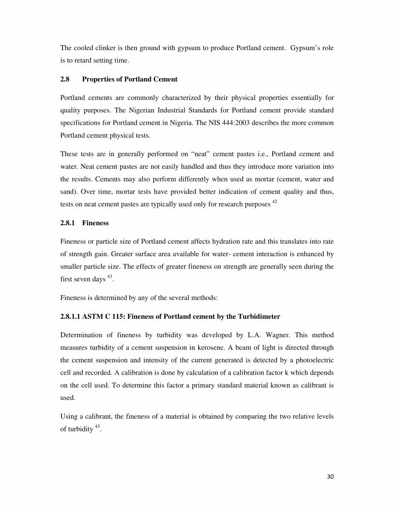
in the clinker. During slow cooling, crystals of almost all clinker components are formed
whereas fast cooling hampers formation of large crystals, causing part of liquid phase to
solidify.
30
The cooled clinker is then ground with gypsum to produce Portland cement. Gypsum’s role
is to retard setting time.
2.8 Properties of Portland Cement
Portland cements are commonly characterized by their physical properties essentially for
quality purposes. The Nigerian Industrial Standards for Portland cement provide standard
specifications for Portland cement in Nigeria. The NIS 444:2003 describes the more common
Portland cement physical tests.
These tests are in generally performed on “neat” cement pastes i.e., Portland cement and
water. Neat cement pastes are not easily handled and thus they introduce more variation into
the results. Cements may also perform differently when used as mortar (cement, water and
sand). Over time, mortar tests have provided better indication of cement quality and thus,
tests on neat cement pastes are typically used only for research purposes 42
2.8.1 Fineness
Fineness or particle size of Portland cement affects hydration rate and this translates into rate
of strength gain. Greater surface area available for water- cement interaction is enhanced by
smaller particle size. The effects of greater fineness on strength are generally seen during the
first seven days 43
.
Fineness is determined by any of the several methods:
2.8.1.1 ASTM C 115: Fineness of Portland cement by the Turbidimeter
Determination of fineness by turbidity was developed by L.A. Wagner. This method
measures turbidity of a cement suspension in kerosene. A beam of light is directed through
the cement suspension and intensity of the current generated is detected by a photoelectric
cell and recorded. A calibration is done by calculation of a calibration factor k which depends
on the cell used. To determine this factor a primary standard material known as calibrant is
used.
Using a calibrant, the fineness of a material is obtained by comparing the two relative levels
of turbidity 43
.

31
2.8.1.2 ASTM C 204: Fineness of Hydraulic Cement by Air Permeability Apparatus
The determination of fineness of hydraulic cement by air permeability was developed by
R.L., Blaine. The principle is that the rate of flow of air through a layer of compacted
particles is proportional to the fineness of the particles. Therefore the test measures the flow
rate of air through a bed of cement particles. This method is also comparative rather than
absolute since it requires a reference material 44
.
The test is carried out by compacting the cement under investigation in a cell of known
volume and fitting it onto a u-tube manometer that contains a non- hygroscopic liquid of low
viscosity and density, for example dibutylphthalate. The cell is attached to the u-tube with a
tight seal and a vacuum is created under the cement sample. Then the air is pushed through
the cement sample by the liquid in the manometer. The time taken by the liquid in the
manometer to travel through a set distance is used to calculate the fineness which is
dependent on sample surface area S defined by the equation
S=Ss √T/√Ts ………15
Where Ss is the surface area of reference material, Ts is time of flow by the reference
material, T is the time of flow of the material under test and S is the surface area of material
under test. Therefore the surface area of the material tested can be calculated from the
reference material 44
.
ASTM C 184: fineness of hydraulic cement by the 150 µm and 75 µm sieves
ASTM C 430: fineness of hydraulic cement by the 45 µm sieve
NIS 448:2003: determination of fineness
The various methods (ASTM C184, C430 and NIS 448:2003) describe fineness as a measure
of coarse particles in a particle size distribution. The content of coarse or/ and fine particles in
a sample is determined by the use of standard sieve meshes which includes: 45, 75, 90,
150,180 and 212 µm.
2.8.2 Soundness
In cement technology, soundness refers to the ability of a hardened cement paste to retain its
volume after setting without delayed destructive expansion 43
. This destructive expansion is
caused by hydration of excessive amounts of free lime or crystallization of free magnesia
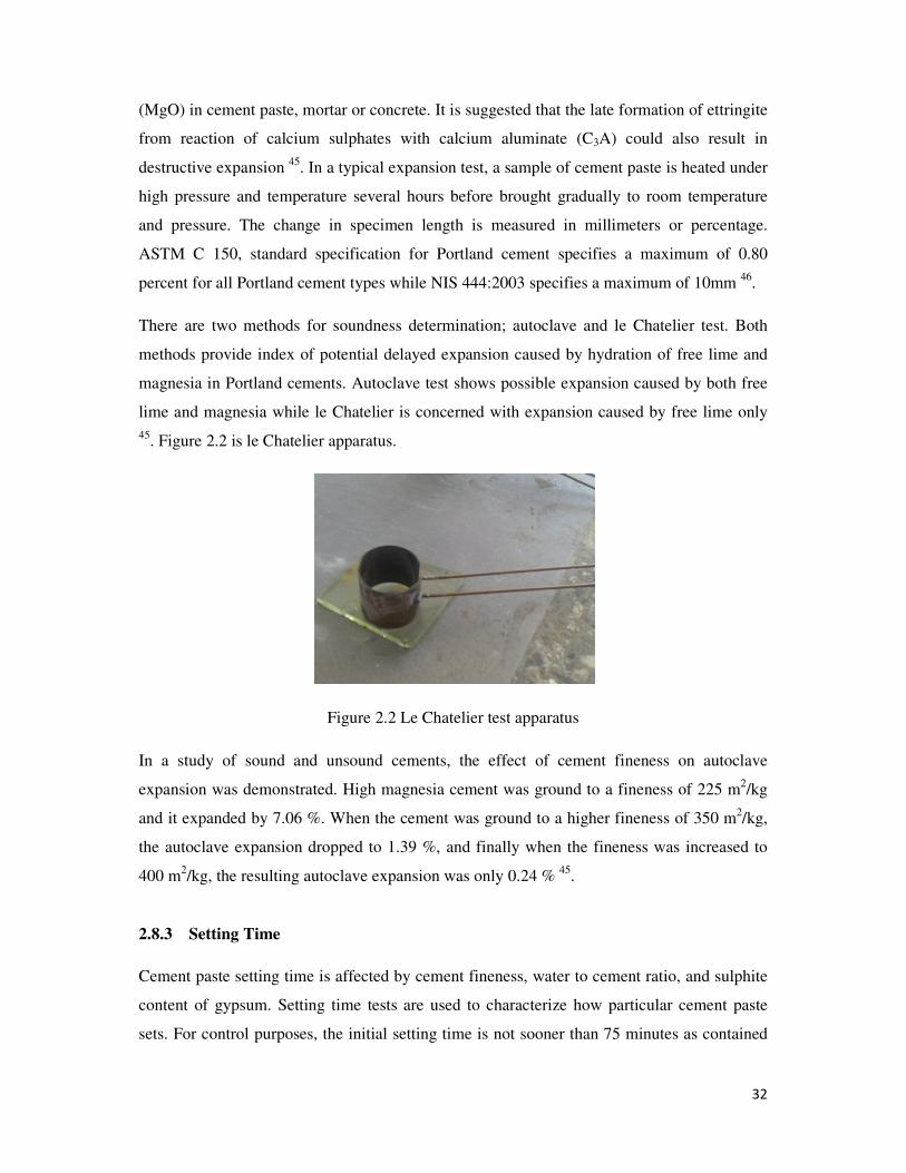
32
(MgO) in cement paste, mortar or concrete. It is suggested that the late formation of ettringite
from reaction of calcium sulphates with calcium aluminate (C3A) could also result in
destructive expansion 45
. In a typical expansion test, a sample of cement paste is heated under
high pressure and temperature several hours before brought gradually to room temperature
and pressure. The change in specimen length is measured in millimeters or percentage.
ASTM C 150, standard specification for Portland cement specifies a maximum of 0.80
percent for all Portland cement types while NIS 444:2003 specifies a maximum of 10mm 46
.
There are two methods for soundness determination; autoclave and le Chatelier test. Both
methods provide index of potential delayed expansion caused by hydration of free lime and
magnesia in Portland cements. Autoclave test shows possible expansion caused by both free
lime and magnesia while le Chatelier is concerned with expansion caused by free lime only
45. Figure 2.2 is le Chatelier apparatus.
Figure 2.2 Le Chatelier test apparatus
In a study of sound and unsound cements, the effect of cement fineness on autoclave
expansion was demonstrated. High magnesia cement was ground to a fineness of 225 m2/kg
and it expanded by 7.06 %. When the cement was ground to a higher fineness of 350 m2/kg,
the autoclave expansion dropped to 1.39 %, and finally when the fineness was increased to
400 m2/kg, the resulting autoclave expansion was only 0.24 %
45.
2.8.3 Setting Time
Cement paste setting time is affected by cement fineness, water to cement ratio, and sulphite
content of gypsum. Setting time tests are used to characterize how particular cement paste
sets. For control purposes, the initial setting time is not sooner than 75 minutes as contained
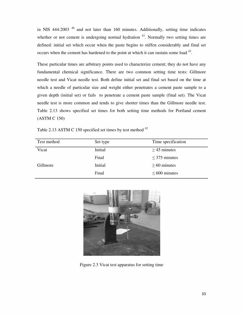
in NIS 444:2003 46
and not later than 160 min
whether or not cement is undergoing normal hydration
defined: initial set which occur
occurs when the cement has hardened to the point at which it can sustain some load
These particular times are arbitrary points used to characterize
fundamental chemical significance. There are two common setting time tests: Gi
needle test and Vicat needle test. Both define initial set and final set
which a needle of particular size and weight either penetrates a cement
given depth (initial set) or fails to penetrate a
needle test is more common and tends to give short
Table 2.13 shows specified set times for both setting time methods for
(ASTM C 150)
Table 2.13 ASTM C 150 specified set times by test method
Test method Set type
Vicat Initial
Final
Gillmore Initial
F
Figure 2.
and not later than 160 minutes. Additionally, setting time indicates
is undergoing normal hydration 43
. Normally two setting times are
when the paste begins to stiffen considerably and final set
occurs when the cement has hardened to the point at which it can sustain some load
These particular times are arbitrary points used to characterize cement; they do not have any
fundamental chemical significance. There are two common setting time tests: Gi
needle test and Vicat needle test. Both define initial set and final set based on the time at
which a needle of particular size and weight either penetrates a cement paste sample to a
initial set) or fails to penetrate a cement paste sample (final set). The Vicat
needle test is more common and tends to give shorter times than the Gillmore needle test
shows specified set times for both setting time methods for Portland cement
ASTM C 150 specified set times by test method 42
Set type Time specification
Initial ≥ 45 minutes
Final ≤ 375 minutes
Initial ≥ 60 minutes
Final ≤ 600 minutes
Figure 2.3 Vicat test apparatus for setting time
33
setting time indicates
. Normally two setting times are
when the paste begins to stiffen considerably and final set
occurs when the cement has hardened to the point at which it can sustain some load 42
.
they do not have any
fundamental chemical significance. There are two common setting time tests: Gillmore
based on the time at
paste sample to a
final set). The Vicat
more needle test.
Portland cement
Time specification
2.8.4 Strength
Cement paste strength is typically defined in three ways: compressive, tensile
These strengths are affected by water
and compaction, curing conditions, size and shape of specimen, loading conditions and
curing age 42
. Since cement gains strength over time, the time at which a strengt
conducted is specified. Typical
taken when doing a cement strength
concrete strength. It is used as a
cement mortars and not on cement pastes
strength. It is usually carried out on cement mortar test specimen. The test specimen is
subjected to a compressive load until f
is described by NIS 446:2003 47
.
Figure 2.4( a) Compressive strength test
strength test
Cement paste strength is typically defined in three ways: compressive, tensile,
strengths are affected by water – cement ratio, cement fineness, aggregate ratio, mixing
, curing conditions, size and shape of specimen, loading conditions and
. Since cement gains strength over time, the time at which a strengt
test times are 2, 7 and 28 days 42
. Two considerations are
cement strength test; cement mortar strength is not directly related to
quality control measure. Secondly, strength tests are done on
cement mortars and not on cement pastes 42
. The most common strength test is compressive
strength. It is usually carried out on cement mortar test specimen. The test specimen is
subjected to a compressive load until failure. Standard test method for strength determination
Figure 2.4 shows a set up for compressive test determination
a
Figure 2.4( a) Compressive strength testing machine,( b) Prism mortars for compressive
34
, and flexural.
aggregate ratio, mixing
, curing conditions, size and shape of specimen, loading conditions and
. Since cement gains strength over time, the time at which a strength test is to be
iderations are
test; cement mortar strength is not directly related to
strength tests are done on
. The most common strength test is compressive
strength. It is usually carried out on cement mortar test specimen. The test specimen is
ailure. Standard test method for strength determination
shows a set up for compressive test determination
b
machine,( b) Prism mortars for compressive
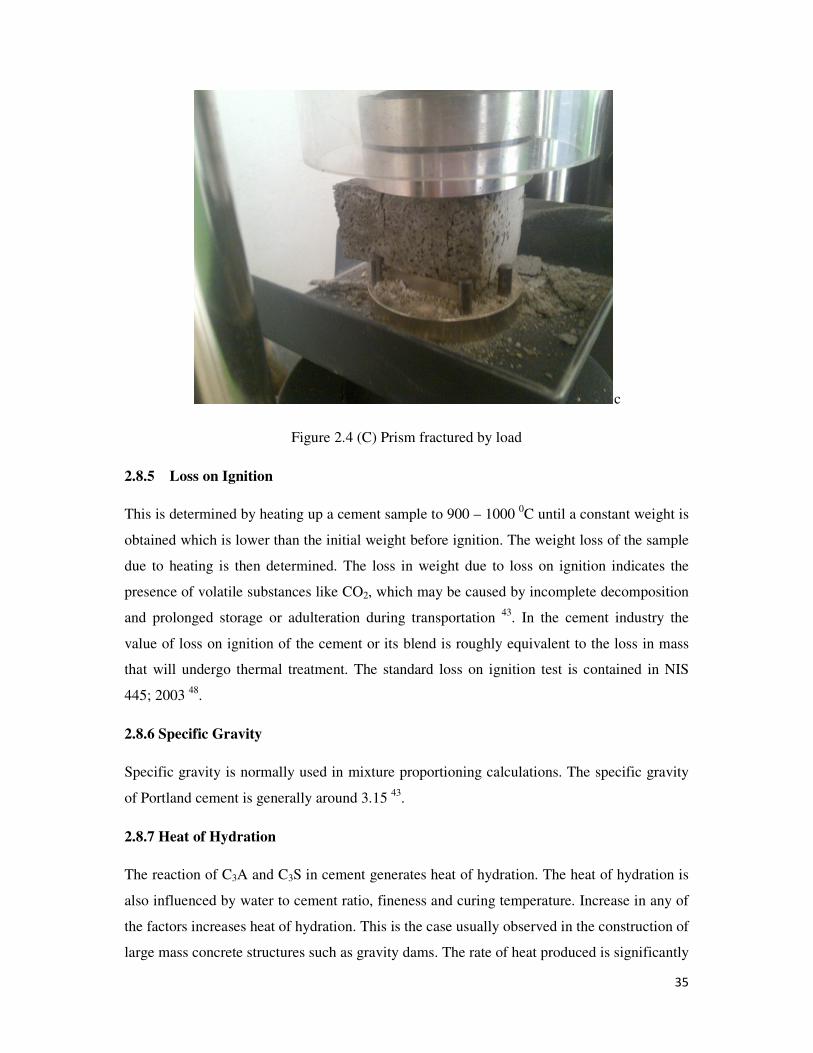
35
c
Figure 2.4 (C) Prism fractured by load
2.8.5 Loss on Ignition
This is determined by heating up a cement sample to 900 – 1000 0C until a constant weight is
obtained which is lower than the initial weight before ignition. The weight loss of the sample
due to heating is then determined. The loss in weight due to loss on ignition indicates the
presence of volatile substances like CO2, which may be caused by incomplete decomposition
and prolonged storage or adulteration during transportation 43
. In the cement industry the
value of loss on ignition of the cement or its blend is roughly equivalent to the loss in mass
that will undergo thermal treatment. The standard loss on ignition test is contained in NIS
445; 2003 48
.
2.8.6 Specific Gravity
Specific gravity is normally used in mixture proportioning calculations. The specific gravity
of Portland cement is generally around 3.15 43
.
2.8.7 Heat of Hydration
The reaction of C3A and C3S in cement generates heat of hydration. The heat of hydration is
also influenced by water to cement ratio, fineness and curing temperature. Increase in any of
the factors increases heat of hydration. This is the case usually observed in the construction of
large mass concrete structures such as gravity dams. The rate of heat produced is significantly
36
faster than it can be dissipated. This in turn creates high temperatures in the center of these
large concrete masses that in turn may cause undesirable stresses as the concrete cools to
ambient temperature. The advantage of high heat of hydration is enjoyed in winter because
favourable curing temperatures are maintained 43
.
2.9 Environmental Impact
2.9.1 CO2 Emissions
Cement manufacturing releases CO2 in the atmosphere when calcium carbonate is heated 49
.
The cement industry is the second largest CO2 emitting industry after power generation. The
cement industry produces about 5 percent of global man made CO2 emissions of which 60
percent is from the chemical process and 40 percent from burning fuel 50
. The amount of CO2
emitted by the cement industry is about 900 kg of CO2 for every 1000 kg of cement produced
51.
2.9.2 Heavy Metal Emission into the Atmosphere
In some circumstances, the emission of heavy metal gases into the atmosphere is influenced
by the composition of the raw materials used, the high temperature calcination
(decomposition) process of limestone and clay minerals. Accompanying heavy metal gases
are dust rich in volatile heavy metals which include thallium, cadmium and mercury 52
. These
heavy metals are often in trace amounts present as secondary minerals in most of the raw
materials. The presence of heavy metals in clinker arises both from the natural raw materials
and from the use of recycled by products or alternative fuels. The high pH prevailing in
cement pore water (12.5 to 13.5) limits the mobility of many heavy metals such as nickel,
zinc and lead by decreasing their solubility and increasing their sorption onto the cement
mineral phases 53
.
2.9.3 Alternative Fuels and By Product Materials
Usually a cement plant consumes 3 to 6 Gigajoules of fuel per ton of clinker produced. This
depends to a large extent on the process used in cement production and also the raw materials
used. Majority of cement kilns today use coal and petroleum coke as primary fuels and to a
lesser extent natural gas and fuel oil. Waste and by products with recoverable calorific value
are suitable fuels used in kilns. These replace fossil fuels like coal. Waste and by products
containing calcium, silica, alumina and iron can be used as raw materials in the kiln,

37
replacing raw materials such as clay, shale and limestone. Because some materials have both
useful mineral content and recoverable calorific value, the distinction between alternative
fuels and raw materials is very slim. For example sewage sludge has a low but significant
calorific value and burns to give ash containing minerals useful in the clinker matrix 53
.
2.10 Cement in Nigeria
One of man’s most pressing needs is housing. The Federal government of Nigeria has
identified this and has set it as a millenium priority. The year 2020 is marked as target to
provide housing for all its citizens. The limitation to this project is the availability of high
quality cement to the construction industry. In fact to achieve this target 20 million tons of
cement is required annually but presently only about 13 million tons or less is in the market 4.
Obviously Nigeria is facing a serious housing and infrastructure shortage. This is largely due
to the inadequacy of cement in the country. The needs in cement are partly offset through
eight cement industries: Dangote Cement Company (Obajana, Ibese and Gboko Plants),
Ashaka cement plant in Bauchi, United cement (Unicem) in Calabar, Cement Company of
Northern Nigeria, Sokoto and Lafarge WAPCO (Ewekoro and Shagamu plants).
In 2008, cement availability to Nigerian market was estimated at 13.4 million tons of which,
54 % was imported 4. By implication the existing manufacturing plants are operating below
50 % of their collective installed capacity. This may explain Nigeria’s invisibleness among
the world leading cement manufacturing countries in the world.
In 2002 the world production of hydraulic Portland cement was 1,800 million tones. The top
three producers of Portland cement are china, India and United States of America. These
three combined about half the world total production with Nigeria producing far less than 0.5
percent 3. In 2005, China led with 43.46 percent followed by India producing 6.38 and then
United States of America with 4.38 percent and Nigeria sharing the final 10.23 percent with
the rest of Portland cement producing countries3.
For more than a decade, China has consistently being the highest producer of cement 3. This
explains why China has the highest carbon dioxide emission in the world. In 2006, China
produced 1.24 billion tons of cement which was 44 % of the world’s total cement production
5. Demand for cement in China is expected to advance 5.4 percent annually and this exceeded
1 billion tons in 2008. Cement consumption in China is expected to hit 44 percent of global

38
demand and China will remain the world’s largest national consumer of cement by a large
margin 6.
The Federal Ministry of Commerce and Industry estimates that the effective demand is
around 20 million tons. According to Ian Furnivall and Tunde Abidoye 4, acute infrastructure
deficit and significant demand for housing has pushed domestic production volumes up to 25
% over the last four years 4. However in 2010, the Federal government of Nigeria, in her
effort to improve the availability of the commodity banned the importation of cement into the
country in order to encourage local production and existing companies are increasing their
capacities. Dangote cement company formerly Benue Cement in Benue State for instance,
increased its capacity from 0.45 million to 2 million per annum in 2008 and now 2.9 to 3
million. In 2010 UNICEM added 2.5 million tons of its capacity to local capacity while
Lafarge WAPCO has planned 2.2 million tons for 2011. With these improved capacities the
quantity of cement in the market have improved slightly and limestone blended cements have
been introduced into the Nigerian market. Today type I or ordinary Portland cement is
substituted completely with limestone blended cement in order to address cement scarcity in
the Nigerian market. Other countries such as Spain, France and Argentina also experienced
similar shortage and based on research results, their standards allowed inclusion of limestone
and other pozzolanic admixtures 7 to allowable limits. For example British Standards (BS
882) allows up to 15 % of limestone to OPC 8.
Limestone Portland cement is widely used in Europe, in fact according to Cement Bureau the
production of limestone Portland cement in Europe increased by 7 % between 2000 and 2010
9. Precisely the inclusion of limestone as an additive to boost quantity in Nigeria started a few
years ago. Benue Cement Company started adding it in 2006. In some European countries
like Germany and Britain, limestone addition to OPC is as high as 35 % 10
. It is reported that
the inclusion of up to 5 % limestone does not affect properties of Portland cement 11
. Blended
cements have certain benefits which include Economic, Environmental and Technical.
The Economic benefit of limestone in Portland cement is the reduced cost of production and
investment which makes cement cheaper 54
. The Environmental advantages include reduction
of CO2 and NO2 emissions due to reduction in clinker content 10
. In terms of technical
benefits, Moir and Kelham observed increased fineness with increase in limestone addition
to OPC and this lead to greater water absorption, improved hydration rates of cement
compounds and consequently increased compressive strength 55
.
39
Investigations on limestone blended cement revealed that the inclusion of 12 to 18 % of
limestone has no significant deleterious effect on strength development and other physical
properties of Portland cement 55-59
.
2.11 Blended Cements
Blended cements usually contain ordinary Portland cement and another cementitious
material. They are made by intergrinding Portland cement with another material. Fly ash,
blast furnace slag, silica fumes and limestone are common cementitious components of
blended cements and each of them results in a different type of blended cement with unique
set of properties. They have gained so much application that the production of ordinary
Portland cements is really on the low side. With the advancement in civil works there is
increasing need for special Portland cements that meet specific requirements with cost of
production being a strong consideration. The American concrete Institute’s Cement
terminology defines blended cements as hydraulic cements consisting essentially of an
intimate and uniform blend of a number of different constituent materials. They are produced
by intergrinding or blending Portland cement with other materials 60
. The use of blended
cement is common in Europe, Canada, Mexico and many other parts of the world. Although
blended cements are used in the United States of America, it is more common for mineral
admixtures such as fly ash and slag. Fly ash generally constitutes 15 to 25 percent by weight
of cement and ground granulated blast furnace slag constitutes 5 to 60 percent and silica
fumes 5 to 12 percent 7. The use of blended cements in Europe is very common and is
continuing to increase. In fact according to Cement Bureau the production of limestone
Portland cement in Europe which is one of the blended cements common in Europe increased
by 7 % between 2000 and 2010 9. Because of the environmental benefits of blended cements
strict environmental regulations have forced European cement manufacturers to focus their
attention on blended cements. European countries promote specific types of blended cements
according to the availability of the cementitious material. For example pozzolana Portland
cement is very common in Italy, Spain and Greece. In Germany, The Netherlands and
Belgium slag Portland cement is widely used. Silica fume is largely blended with Portland
cement in Norway, Iceland and France 7.
In these countries and many others cooperation between cement manufacturers and the
producers of the cementitious or supplementary materials exists. This cooperation has lead to
improved quality of these materials used in blended cements 7.
40
2.12 Supplementary Materials Used in the Manufacture of Blended Cements
Most of the materials used in the manufacture of blended cements are waste products from
industrial processes and they vary in quality. Examples of such are: high calcium fly ash,
ground granulated blast furnace slag, condensed silica fume and rice husk ash. The natural
ones include volcanic ash. These are common amongst European countries. Elsewhere like in
Ghana of Africa and India limestone is widely used in the manufacture of blended cement.
Blended cements may be Portland cement and one supplementary material or Portland
cement with more than one supplementary material. When it is a two component material it is
a binary system blend and the other ternary system blend. These systems are designed to
attain desired performance characteristics that may be difficult to achieve in a binary blend or
only Portland cement or even in the ternary system blends 61, 62
.
2.12.1 High Calcium Fly Ash (HCFA)
HCFA is residue collected from smokestacks of coal fired power plants generally using
lignite and /or bituminous coals. They have been combined with lime to produce moderately
strong concrete 63, 64
. Cements made with this material are pozzolanic. Pozzolanic materials
are silica or alumina containing materials which react with calcium hydroxide at room
temperature to form cementious compounds. These blended cements are common in China
and the United States of America 64
.
2.12.2 Ground Granulated Blast Furnace Slag
This is a product of iron smelting. It is mildly cementitious in itself until combined with
cement and water. It is formed by the reaction of limestone with materials rich in silica and
alumina associated with the ore or present in ash from the coke 65
. It improves strength at
later age 66
. The chemical composition of granulated blast furnace slag is similar to that of
Portland cement. Compared with Portland cement, the contents of silica and alumina are
higher but its lime is lower. The composition of blast furnace slag varies depending on the
nature of the ore, the composition of the limestone, the coke and the kind of iron produced 1.
It is widely used in Europe 63
.
2.12.3 Condensed Silica Fume
This is obtained from silicon metal industries. It is a super fine powder of almost pure silica.
It is the favourite for very high strength concretes used in the construction of high rise

41
buildings. It is often used in combination with cement and fly ash 63
. Because they are so
effective at increasing performance of cement, it is usually used as secondary additive in
ternary blended systems to develop the overall quality of the cement.
2.12.4 Rice Husk Ash
This is the least considered in terms of quality but considered promising on a global scale.
The world’s primary stable crop is rice. The milling of rice generates 100 million tons of
husks annually in India. Rice husk ash behaves like silica fume if the ash is generated at low
temperature and ground to fine particle size 61, 63
.
2.12.5 Volcanic Ash
This material comes about as a result of volcanic activity when silica rich magma meets with
large quantities of underground water in volcanic conduits. Under high temperature and
pressure the steam reacts with the dissolved carbon dioxide and sulphur gases and during the
volcanic eruption the magma produces material with excellent cementing characteristics. This
is the pozzolan used prior to the discovery of Portland cement in Italy and Greece 63, 67
.
2.13 Benefits of Blended (Composite) Cements
Modern blended cements have come into their class as increasing care has been taken to
develop high quality composite cements which far out perform traditional cements. Certainly
their increased usage is a result of favourable benefits which when grouped together fall
under the following headings:
2.13.1 Economical Benefits
Blended cements have replaced up to 60 percent of ordinary Portland cement and are
successful in civil applications. When cheaper supplementary material replaces portion of
Portland cement there is low cost of production and low investment costs per ton of cement 7,
54.
2.13.2 Technical Benefits
In general terms siliceous materials react with the calcium hydroxide in hydrated cement
paste to produce calcium silicate hydrates that yield higher strength. This is brought about by
improved fineness which is a property of blended cements. Higher fineness increases
42
retention of water which consequently improves hydration rates 7, 55
. Others include improved
concrete workability and lower risk of thermal cracking.
2.13.3 Environmental Benefits
There is reduction in the emission of carbon dioxide and other greenhouse gases as quantities
of clinker are replaced with lime containing supplementary materials that do not undergo
thermal treatment 10
.
2.14 Limestone as a Supplementary Material in Blended Cement Production
The inclusion of limestone in Portland cement has both economic and environment friendly
benefits like other blended cements. It also improves the performance of concrete with
respect to strength, durability and workability 59
. European Nations standard (EN 197-1)
permits the addition of 6 - 35 % of limestone to OPC. Under the EN 197-1 classification of
cements limestone Portland cement is type II/AL for 6-20 % limestone and type II/BL for 21-
35 % limestone addition to OPC 66
.
Limestone as discussed earlier is a naturally existing mineral that consists primarily of
calcium carbonate. The chemical composition of limestone varies widely depending on the
route by which they were formed.
Standard EN 197-1 requires in Portland limestone cement limestone with at least 75 percent
calcium carbonate by weight, with less than 1.2 percent clay and less than 0.2 percent organic
material. One of the impurities in limestone is magnesium carbonate and is deleterious for
concretes. Consequently its content is required not more than 4 percent.
Since the European standard for common cement was first published in 1993 there has been
an increasing trend in the use of limestone as a mineral addition in cement not only in the
European countries but also in other parts of the world. Limestone is semi inert and
contributes to concrete’s microstructure. Limestone addition considerably influences the
characteristics of cement but this influence depends on a number of factors which include
clinker type, fineness and limestone quality 68
. When interground with Portland cement
clinker it improves particle size distribution. The fine limestone particles act as nucleation
sites increasing the rate of hydration of the silicates.
43
2.15 Effect of Limestone on Properties of Portland Cement
2.15.1 Particle Size Distribution and Fineness
Limestone is softer than clinker and therefore lesser energy is needed to grind it attain
comparable fineness with clinker. Studies showed a decrease in energy when clinker and
limestone were ground together to give same fineness either had when ground alone. It was
revealed that Portland limestone cement gave a wider particle size distribution than that of
cement interground with fly ash or natural pozzolana. Addition of limestone to OPC requires
higher fineness or increased grinding time to achieve strength of OPC. This was observed in
the same study as limestone did not only increase the grinding time required to obtain target
compressive strength of 40 MPa, but also increased fineness considerably 58
. The particle size
distribution of limestone and clinker after intergrinding was investigated and clinker
concentrated in coarser fraction and limestone in the finer. As the limestone content and
grinding time increased, the particle size distribution became wider and finer. This means that
longer grinding time change amount of coarse particle for lower limestone contents but affect
the entire size distribution at higher limestone content. Limestone composite cements are
usually ground to very high Blain (surface area) values in order to obtain the desired
compressive strength. However the trend of fineness and Blain values do not go parallel to
each other at higher limestone percentages 69
. Studies by Voglis et al reveal the easiness of
grinding between limestone, fly ash and natural pozzolana all at 15 percent. In order of
increasing ease of grindability, the raw materials were listed as limestone, fly ash, natural
pozzolana and finally clinker. However the targeted Blaine values in order to achieve
required strength and grinding times were found highest in the case of limestone blended
cements as can be seen in Table 2.14 58
. Grindability of limestone blended cements when
investigated at different limestone addition percentages of 10, 20, 30 and 40 and at different
grinding times (35, 50, 65, 85 minutes) showed a widening particle size with increasing
Blaine values 69
. However both the grindability of clinker and limestone were negatively
affected in the case of 40 % limestone addition and lower fineness values of clinker and
limestone were measured when compared to 30 % limestone addition 69
.
In a physical and mechanical properties investigation on cements prepared by replacing 0, 6,
21 and 35 % of clinker with limestone at constant blain showed limestone blended cement
having increased fineness 70
.
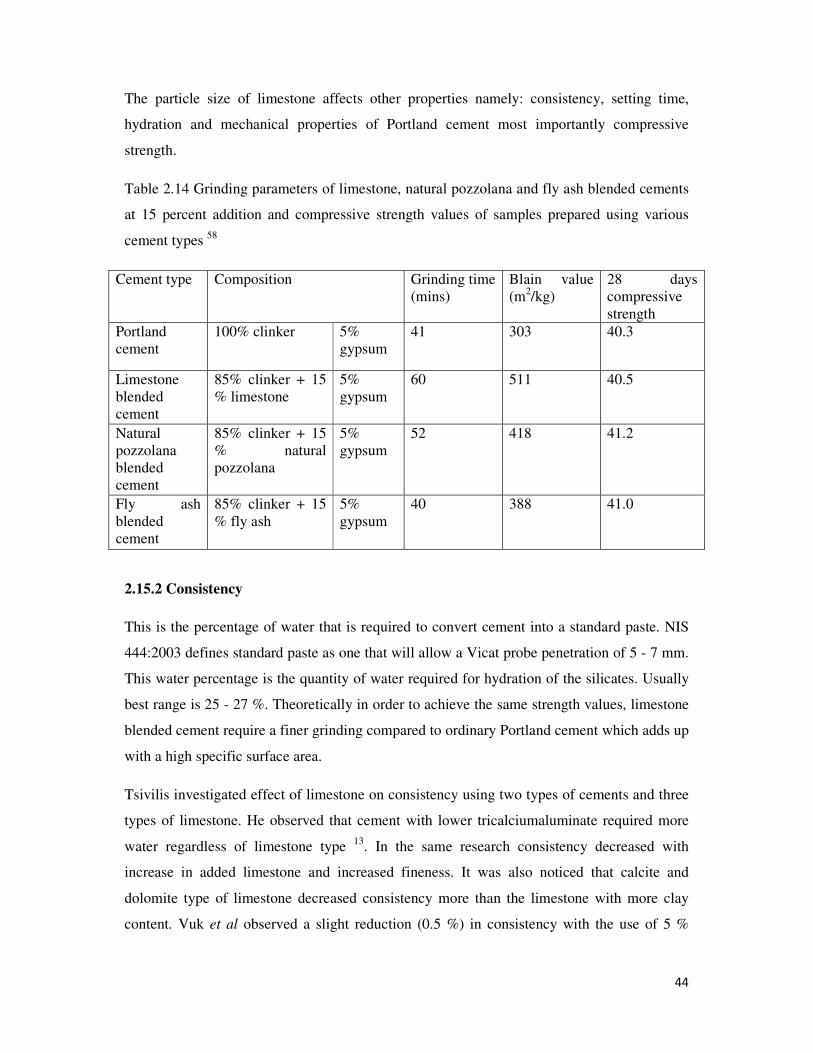
44
The particle size of limestone affects other properties namely: consistency, setting time,
hydration and mechanical properties of Portland cement most importantly compressive
strength.
Table 2.14 Grinding parameters of limestone, natural pozzolana and fly ash blended cements
at 15 percent addition and compressive strength values of samples prepared using various
cement types 58
Cement type Composition Grinding time
(mins)
Blain value
(m2/kg)
28 days
compressive
strength
Portland
cement
100% clinker 5%
gypsum
41 303 40.3
Limestone
blended
cement
85% clinker + 15
% limestone
5%
gypsum
60 511 40.5
Natural
pozzolana
blended
cement
85% clinker + 15
% natural
pozzolana
5%
gypsum
52 418 41.2
Fly ash
blended
cement
85% clinker + 15
% fly ash
5%
gypsum
40 388 41.0
2.15.2 Consistency
This is the percentage of water that is required to convert cement into a standard paste. NIS
444:2003 defines standard paste as one that will allow a Vicat probe penetration of 5 - 7 mm.
This water percentage is the quantity of water required for hydration of the silicates. Usually
best range is 25 - 27 %. Theoretically in order to achieve the same strength values, limestone
blended cement require a finer grinding compared to ordinary Portland cement which adds up
with a high specific surface area.
Tsivilis investigated effect of limestone on consistency using two types of cements and three
types of limestone. He observed that cement with lower tricalciumaluminate required more
water regardless of limestone type 13
. In the same research consistency decreased with
increase in added limestone and increased fineness. It was also noticed that calcite and
dolomite type of limestone decreased consistency more than the limestone with more clay
content. Vuk et al observed a slight reduction (0.5 %) in consistency with the use of 5 %
45
limestone. He agreed that the more important parameter influencing consistency was fineness
69. A possible explanation is that the limestone fills the voids between the clinker particles.
A study by Inan Sezer showed decrease in consistency when limestone and clinker were
ground together. In the study grinding time was kept constant for all cements. Blended
cements with higher Blaine values were found coarser compared to cement without any
additive when sieves 32 and 90 micron sieves were used 71
. It is reported that Erdogbu
prepared blended cements with 5, 10, 20 and 30 percent limestone additions and consistency
was observed decreasing with increased limestone percentage. The decrease in consistency
was attributed to the smooth surface and lower porosity of limestone particles after grinding.
However strength values of blended cements were found lower than the required strength in
higher limestone replacements. Erdogbu suggested that limestone blended cements must be
ground finer 71
.
A study on the effects of limestone replacement at 15, 25, 35 and 45 % where grinding of
ingredients was separately done before mixing revealed that consistency of 26 to 27 percent
was required to get a Vicat plunger penetration of 30±5 mm 72
.
2.15.3 Hydration
Portland cement when mixed with water, its compounds (C3S, C2S, C3A and C4AF) react
with water to form hydrates. These reactions lead to the setting and hardening of the cement.
It is assumed that the reactions of each compound take place independently. The main
reactions of the individual cement compound are described thus.
1. The C3S and C2S react with water to produce calcium silicate hydrate (CSH) and
calcium hydroxide (CH)
2. The C3A not only reacts with water directly but also reacts with gypsum
(CaSO4.2H2O) to produce ettringite. Once all the gypsum is used up, the ettringite
becomes unstable and reacts with remaining C3A to produce monosulphate aluminate
hydrate crystals
3. Like C3A, C4AF reacts with gypsum water to form ettringite, lime and alumina
hydroxides. The complete product is attained by further reaction of C4AF with
ettringite.
The above reactions are accompanied by heat liberation. The liberated heat of hydration is
one method to determine degree of hydration.

46
The hydration of cementitious materials generally is exothermic. A variation in the liberated
heat of hydration mirrors the hydration mechanism of the hydrating material. A heat
evolution curve illustrated by Mindess and Young41
shows the 4 stages of hydration
1. Pre-induction stage
The fast heat evolution was attributed to the hydration of C3A, the hydration of free lime
and the wetting of the cement. In this stage C3A is most active and reacts with gypsum to
produce ettringite. The main products are ettringite and calcium hydroxide. The duration
of this stage is only several minutes.
2. Dormant stage
In this stage, cement has a low reactivity. This period last for about 5 hours
3. Acceleration stage
This acceleration is due to hydration of C3S. The mechanism of this acceleration is
described as a transport of ions to and from the surface of anhydrous particles through a
gradually thickening shell. After about 12 hours this stage ends. The main products are
calcium silicate hydrates and calcium hydroxide. This is the initial setting of the cement.
4. Post- acceleration stage
After the second peak, the rate of heat liberation slows down. The hydration of C2S
becomes the main contribution to this stage. The presence of a shoulder was suggested to
be due to conversion of ettringite to monosulphate aluminate hydrate and the formation of
secondary ettringite. The main products in this stage (final setting) are calcium silicate
hydrate, calcium hydroxide and monosulphate aluminate hydrate crystals
Figure 2.5 Schematic presentations of rates of heat evolution 73

47
Degree of hydration α (t) is defined as the ratio between the amounts of cement that has
reacted (that has been dissolved) at time t, relative to the original amount of cement:
α (t) = amount of cement that has reacted at time t ………16
total amount of cement at time t=0
Several theories for the determination of the degree of hydration have been proposed. Among
these methods, isothermal conduction calorimetry is the most convenient and most useful one
73.
α (t)≈ α(Q(t)) = Q(t)/Qpot ……….17
Where Q (t) (J/g) is the total heat liberated at time t obtained by integration of rate of heat
evolution and Qpot (J/g) is the potential heat when all the cement has reacted. Qpot is
calculated from the clinker composition of the cement and the heat of hydration of the
individual constituents:
Qpot = q1×(C3S) + q2×(C2S) +q3× (C3A) +q4× (C4AF) +q5× (C) + q6 ×(MgO) ………18
Where, q1 to q6
(J/g) are the heats of hydration of the constituents.
The presence of limestone in Portland cement promotes nucleation as it acts as nucleation
sites for hydration products, therefore the inclusion of limestone could increase the rate of
hydration reaction. Hydration of cement pastes at various water- cement ratios (20 % - 50 %)
with 10 % and 20 % limestone addition showed a more rapid reaction at 7 days age curing in
water in the higher w/c ratio pastes containing limestone 57
. In a similar investigation with
concrete mixtures at 34 % and 50 % w/c containing 10 and 20 % limestone, hydration
increased with increase in limestone content 56
. A computer model was employed using
CEMHYD3D program to predict the hydration and strength development of low w/c cement
pastes with varying limestone percentage. Limestone was used to replace 20.5 % and 30.8 %
of clinker at 0.25 water to cement ratio, and 14.5 % and 22.3 % at 0.30 water to cement ratio.
This showed the degree of hydration of pastes containing limestone being higher than the
control sample i.e. cements without limestone at all curing ages. From a comparative study of
the computer model and that done in reference 56, it is observed that coarse cement particles
hydrate slower which may be attributed to large volume to surface area.
The mechanism of hydration was studied at early ages of finely ground limestone and quartz
powder intermixed with Portland cements with different compositions. It was determined that

48
both of these material additions activated or slowed down the hydration rate depending on the
cement compositions. When cement with high C3A content was used hydration reactions
sped up for both types of materials and it was determined that these materials act as nucleus
for rapid formation of hydration products. In the case of low C3A content cement, the
addition of these materials retarded hydration 74
. The hydration of fly ash and slag at selected
levels of addition to OPC were studies using X-ray diffraction and differential thermal
analysis in comparison with limestone added to OPC. It was concluded that the hydration
reaction of ordinary Portland cement in the presence of powdered limestone and lime sludge
was more accelerated and greater amount of calcium hydroxide was liberated. With further
investigation it was concluded that hydration of OPC with lime sludge is better than with
limestone due to better crystallinity and fineness of powdered sludge 75,76
.
An investigation using isothermal calorimetry revealed that more hydration activity occurred
in cement containing 50 % limestone than in the absence of it under comparable conditions
77. This is the accelerating effect of limestone. Xiong and Van Breugel using isothermal
calorimetry found that the limestone additions gave an earlier peak and faster rates of
hydration at 200C than those of control paste at water to cement ratio of 0.43. At higher water
to cement ratio the hydration was earlier but did not produce the same activity as the control
mixture 78
.
Limestone affects hydration of both C3A and C3S. The addition of limestone accelerates their
hydration. Barbara et al investigated the effect of limestone on blended cement using
isothermal calorimetry. The rate of heat liberated from the blended cement was higher than
that from OPC. An X-ray diffractionometry employed in the study to show hydrate formation
revealed the formation of calcium carbosilicate hydrate. Barbara et al concluded that calcium
carbonate (limestone) not only modifies the hydration of C3S but also reacts with it to form
calcium silicate hydrate 77
.
In a typical heat evolution curve of Portland cement blended with limestone shown in Figure
2.6, it is seen that the addition of the limestone shortened the dormant stage, accelerated the
early hydration and resulted in an additional peak in the heat evolution curve around 12 hours
hydration.
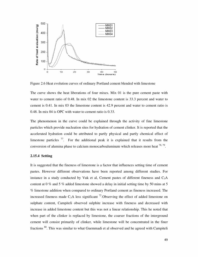
49
Figure 2.6 Heat evolution curves of ordinary Portland cement blended with limestone
The curve shows the heat liberations of four mixes. Mix 01 is the pure cement paste with
water to cement ratio of 0.48. In mix 02 the limestone content is 33.3 percent and water to
cement is 0.41. In mix 03 the limestone content is 42.9 percent and water to cement ratio is
0.48. In mix 04 is OPC with water to cement ratio is 0.33.
The phenomenon in the curve could be explained through the activity of fine limestone
particles which provide nucleation sites for hydration of cement clinker. It is reported that the
accelerated hydration could be attributed to partly physical and partly chemical effect of
limestone particles 77
. For the additional peak it is explained that it results from the
conversion of alumina phase to calcium monocarboaluminate which releases more heat 78, 79
.
2.15.4 Setting
It is suggested that the fineness of limestone is a factor that influences setting time of cement
pastes. However different observations have been reported among different studies. For
instance in a study conducted by Vuk et al, Cement pastes of different fineness and C3A
content at 0 % and 5 % added limestone showed a delay in initial setting time by 50 mins at 5
% limestone addition when compared to ordinary Portland cement as fineness increased. The
increased fineness made C3A less significant 72
.Observing the effect of added limestone on
sulphate content, Campiteli observed sulphite increase with fineness and decreased with
increase in added limestone content but this was not a linear relationship. This he noted that
when part of the clinker is replaced by limestone, the coarser fractions of the interground
cement will consist primarily of clinker, while limestone will be concentrated in the finer
fractions 80
. This was similar to what Guemmadi et al observed and he agreed with Campiteli
50
as he did not observe a clear trend as setting time varied with fineness 75, 81
. Hooton et al
reported that Moir and Kelham also observed that increased fineness gave longer initial set
time at 20 % limestone replacement55
.
2.15.5 Compressive Strength
The strength of concrete made with limestone composite cement is influenced by the quality
of limestone, manufacturing process and final particle size distribution of cement. Obviously
the soft nature of limestone will make limestone cement have finer particle size than OPC,
thus high strength at early stage is expected. Series of cement samples with limestone
contents 0, 3, 5.5 and 8 % prepared at approximately equal Blaine and equal sieve were
studied. In these test, limestone of 85 % total carbonate was used with clinker of C3A content
of 5.1%. The result of 3 and 5.5 % added limestone showed comparable strengths with OPC
but at higher limestone percentage the Portland limestone cement was ground to higher
surface area to have similar strength value 11
.
At higher limestone additions strength loss may be due to dilution of C3S and C2S and this
must be compensated for by finer grinding. This was illustrated in a study that showed
comparable strength for ordinary Portland cement and Portland limestone cement with 15 %
limestone. Portland limestone cement was ground to 511m2/kg compared with 303 m
2/kg for
ordinary Portland cement as shown in Table 2.14 58
. Three cements from the same
manufacturing plant with 0, 8.3 and 18 % limestone had Blaine values of 317, 372 and 420
m2/kg respectively. Concretes produced with these cements achieved 28 day strength as 40.2,
38.1 and 36.3 MPa 56
.
Data published by Benachour and Dhir agree that the strength of concrete is reduced when
ground limestone are blended with ordinary Portland cement. Benachour concluded that the
performance of concrete produced with cement containing 25 percent limestone was
equivalent to what would be expected due to a 25 percent replacement of the Portland cement
with an inert diluent 82
. Dhir concluded that there were minor differences in the performance
of concrete with Portland cement and Portland limestone cement containing 15 percent
limestone but that above this level the water to cement ratio of the concrete should be reduced
by 0.08 for every 10 percent limestone to achieve the same compressive strength at 28 days
curing 83
.
51
These studies have revealed with regards to strength development of limestone Portland
cement that the appropriate choice of clinker quality, limestone quality, and percentage
limestone and cement fineness can lead to the production of limestone composite cement
with desired properties. However higher rates of limestone addition usually reduces the
compressive strength.
2.16 Limestone Reactions in Limestone Cements
It is reported that low amounts of limestone reacts completely to form various carboaluminate
phases. The extent of limestone’s reactivity is controlled by the amount of sulphate in the
system. As the sulphate increases, the likelihood of unreacted carbonate increases. Campiteli
and Florindo were reported to have observed that increased limestone addition decreased the
optimum sulphate content in both fine and coarse cements. However they concluded that
decreases in sulphate would not be sufficient for complete reaction at high limestone addition
levels as they observed beyond 14 percent limestone addition 81
. This may possibly be as a
result of the decrease in quantity of the fine clinker particles, although this decrease may not
be linear as would be expected from addition of limestone. Compressive strength as shown in
a study by Caldarone decreased with increase in added limestone but increase was observed
at about 7.5 percent addition after one day strength development. He suggested that the ratio
of CO3 to C3A probably gives more of monocarboaluminate than sulphate aluminate species
and this contributes to cement strength 81
. Hydration of C3A in the presence of calcium
carbonate results in calcium carbosilicate hydrate and strength is enhanced 75, 76
.
Tsivilis determined the effect of reactivity of limestone with OPCs of varying C3A contents
as observed by measuring compressive strength. Clinker with lower C3A (7.54 %) and higher
C3S (65.15 %) gave lower compressive strengths at all curing times and at all percentages of
added limestone to OPC of higher C3A (11.74 %) and lower C3S (57.99 %) 13
.
Suggestions are that some CaCO3 could be incorporated in calciumsilicate hydrate formed by
hydration C3S. However, the formation of ettringite is under debate. Authors like Tsivilis and
Kakali are reported to have found delayed formation of ettringite where limestone was added
to OPC, while Ingram et al found that ettringite formation proceeded normally in a similar
system. Others observed accelerated formation of ettringite. In other words such limestone
composite cements had earlier setting than OPC. This is possible due to the production of
calcium hydrate which is produced during dilution of limestone. Limestone also acts as a
nucleation site for enhanced calcium formation. Thus the nucleation and dissolution of
52
limestone are possible factors that lead to accelerated ettringite formation. Furthermore, the
microscopic structures of the calcium hydrate crystals in limestone composite cements are
responsible for accelerated formation of ettringite. The rate of formation of ettringite easily
translates to high early strength development within few days and reduces as days go by. This
was observed in an investigation by Barker and Cory. They observed enhanced formation of
calcium hydrates at early age with 5 % and 25% added limestone 25 % added limestone to
OPC 55
. Be that as it may, there is co-formation of carboaluminate hydrate with ettringite.
Investigations by Ingram et al and Klem and Adams were concluded that though calcium
carboaluminate and ettringite form in a competitive fashion since CO3 and C3A compete for
sulphite ions, the calcium carboaluminate is less stable and so the formation of ettringite will
proceed normally 83,84
.
2.17 Effect of Limestone on Concrete Properties
Properties that characterize concretes include Workability, resistance to sulphate attacks,
permeability and drying shrinkage.
2.17.1 Workability
The effect of limestone on workability of freshly prepared concrete is much related to particle
size distribution of the limestone in relation to the cement. Generally, fine limestone particles
can enhance the overall particle packing of the cement resulting in less space for water
between the solid grains. By definition, workability is that property determining the effort
required to manipulate a freshly mixed quantity of concrete with minimum loss of
homogeneity.
Research showed that decrease in average particle size of limestone used to replace OPC
partially gave better early age properties. Finer particles accelerate hydration. In the study
torque viscosity and flow resistance in concretes with a water to cement ratio of 0.33 were
measured using limestone with particle size of 0.7 and 3 micrometers average size limestone
particles( up to 20 percent) blended with ordinary Portland cement with varying amounts of
silica fume. The amount of limestone did not significantly affect the flow resistance but the
torque viscosity decreased with increasing limestone additions. In the same study the finer
limestone particle sizes approached that of silica fume (0.26 microns) and it was postulated
that the absorption of admixtures is notably higher for silica fume than for limestone 82
.
Decreased workability was observed with increased limestone addition by Bonavetti . A 0.01
increase in water to cement ratio was required to achieve equal slump from 0 to 5 percent
53
limestone and another 0.01 increase for limestone addition from 5 to 25 percent 57, 78
.
Information from these investigations established that water requirement is primarily related
to inter particle space.
2.17.2 Sulphate Resistance
Structures exposed to soils or ground water containing high concentration of sulphate ions
often experience sulphate attack. This has a deleterious effect on concrete. It is reported that
proper initial curing of blended concrete made with Type V (low alumina content) cement
with low water cement ratio were recommended as methods to resist sulphate attack.
However significant changes in cement chemistry have resulted in cement with a low silicate
ratio for sulphate environments. This is because higher silicate ratio cements results in
increased calcium hydroxide content in the hardened cement matrix, consequently enhancing
the susceptibility of such cements to the softening ability of sulphate attack 85, 86, 87
.
Generally, limestone in cements dilutes C3A and other active aluminate content of cements.
The formation of carboaluminate from reaction of calcium aluminates and limestone reduces
available alumina participation in deleterious sulphate reactions. On the other hand the use of
limestone composite cements result in lower strength and it is believed that it could facilitate
the ingress of external sulphates. Hooton claims that there is no evidence of deleterious
effects of up to 5 percent limestone in cements. Thus increased quantities of finely ground
carbonates could increase the potential for sulphate attack 59
.
In an investigation to monitor sulphate resistance of limestone blended cements with other
mixtures, 10- 40 percent ground limestone were added to OPC and compared with cements
made with same additions of calcium fluoride. The mortar bars were exposed to 5 percent
sodium sulphate and length change and time it took to crack were monitored. The results
shown in Table 2.15 showed that time taken to crack increased with increased limestone
replacement where as calcium fluoride replacements had no effect in spite of both fillers
having increased strength at time of sulphate exposure. It was suggested that the
improvement in sulphate resistance is possibly due to the formation of calcium
carboaluminate, thus suppressing formation of monosulphate and therefore reducing the
potential for ettringite formation on exposure to sulphate solution 88
. From the data Table
2.15 it is seen that the calcium carbonate (CaCO3) has a more beneficial effect.
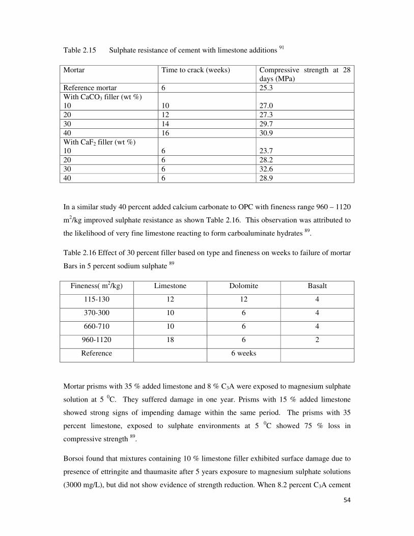
54
Table 2.15 Sulphate resistance of cement with limestone additions 91
Mortar Time to crack (weeks) Compressive strength at 28
days (MPa)
Reference mortar 6 25.3
With CaCO3 filler (wt %)
10
10
27.0
20 12 27.3
30 14 29.7
40 16 30.9
With CaF2 filler (wt %)
10
6
23.7
20 6 28.2
30 6 32.6
40 6 28.9
In a similar study 40 percent added calcium carbonate to OPC with fineness range 960 – 1120
m2/kg improved sulphate resistance as shown Table 2.16. This observation was attributed to
the likelihood of very fine limestone reacting to form carboaluminate hydrates 89
.
Table 2.16 Effect of 30 percent filler based on type and fineness on weeks to failure of mortar
Bars in 5 percent sodium sulphate 89
Fineness( m2/kg) Limestone Dolomite Basalt
115-130 12 12 4
370-300 10 6 4
660-710 10 6 4
960-1120 18 6 2
Reference 6 weeks
Mortar prisms with 35 % added limestone and 8 % C3A were exposed to magnesium sulphate
solution at 5 0C. They suffered damage in one year. Prisms with 15 % added limestone
showed strong signs of impending damage within the same period. The prisms with 35
percent limestone, exposed to sulphate environments at 5 0C showed 75 % loss in
compressive strength 89
.
Borsoi found that mixtures containing 10 % limestone filler exhibited surface damage due to
presence of ettringite and thaumasite after 5 years exposure to magnesium sulphate solutions
(3000 mg/L), but did not show evidence of strength reduction. When 8.2 percent C3A cement
55
was replaced with a zero percent C3A cement, the surface damage with 10 percent limestone
was mitigated. In lower sulphate exposures (300 and 750 mg/L), no damage was observed
after 5 years 86
.
In a study a comparative study of strength losses between a control paste mixture and mixture
containing 10 percent limestone, when subjected to 10 percent magnesium sulphate solution
at 60 oC, revealed that both samples exhibited similar loss in strength. When immersed in 10
percent magnesium sulphate at 20 oC, strengths after 180 days were similarly unaffected for 0
and 10 percent limestone pastes, while 5 percent limestone showed increased strength similar
to that of 40 percent slag paste 85
.
56
CHAPTER THREE
3.0 EXPERIMENTAL
3.1 Materials and Methods
3.1.1 Materials
The primary materials were clinker, gypsum and limestone.
3.1.2 Reagents
All reagents were analaR grade purchased from Tedia, Merck, Riedal de-Haen, Hopkins &
Williams, Fisher, BDH and Lab tech chemicals. Barium chloride, ammonium acetate, (98.0
% w/w), copper complexonate indicator and calcein indicator were purchased from Merck
company, Germany. Conc. Hydrochloric acid, (37 % w/v), ethylene glycol (1, 2-ethanediol)
and ethanol (0.79 g/cm3) were purchased from Tedia chemicals, USA. Silver nitrate and
ethylene diaminetetraacetic acid, EDTA (99.0 % w/w) from Fisher Scientific Company,
USA. Sulphosalicylic acid indicator and sodium hydroxide from BDH, England. Ammonium
hydroxide from Hopkins and Williams, England, PAN (1,2-pyridylazo-2-naphthol ) indicator,
triethanolamine and potassium hydroxide from Riedel-de Haen, Germany, while
bromocresol green (BCG) was purchased from lab tech chemicals.
3.1.3 Apparatus
Normal laboratory glass wares (borosilicate), polyethylene vessels, pH meter (Jenway, sr
30102), weighing balance (mettler toledo, ML 4002E/01) porcelain crucibles (GmbH),
electric furnace (CONTROLS,10- D1418/A) dessicator, magnetic stirrer and hotplate
(Gallenhamp, 14/ss-660), filter papers (Whatman No. 40 and 42), bunsen burner, retort stand
with wire gauze, 100 oC thermometer, thong, jaw crusher, disc mill (Retsch, BB200)
laboratory cement mill (H-Welte, BGSTAK 4E/S 1980 model), quartering machine (locally
fabricated), cement mixer (CONTROLS, 65-L0006/AM, EN 196-1), air permeability
apparatus (Toni-Teknik, 870 1992 model), sieve machine (Alpine 200LS-N), 45,90 and 180
µm sieves (BS 140-1). Compressive strength machine (CONTROLS, 65-L11V2), jolting
apparatus with prism gang (CONTROLS, 65-L0012/E), Vicat apparatus with plunger, needle
and ring pin attachment (Toni-Teknik), electric water boiler (CONTROLS, 62-L0025/F)
electric water bath (Memmert, W200), Erlenmeyer flask, Gooch crucible and suction pump.
57
3.1.4 Sampling and Sample Preparation
The limestone was obtained from Tsekucha quarry in Gboko, Benue state. It was crushed
with a jaw crusher and quartered using a quartering machine. The quartered portion was
stored in polyethylene sample bag as limestone parent sample (LPS). In similar way all
materials were labeled parent samples. Clinker and gypsum were obtained from a local
cement manufacturing industry. The clinker was sampled at two hours interval for a period of
24 hours. The sampled clinker was homogenized and quartered. The quartered sample was
crushed with the jaw crusher and stored in polyethylene sample bags and labeled as clinker
parent sample (CPS), to be used for formulation of composite and ordinary Portland cements.
The obtained gypsum was similarly stored and labeled gypsum parent sample (GPS).
3.2 Methods
3.2.1 Analysis of Limestone
3.2.1.1 Determination of Calcium Carbonate in Limestone
1g of limestone sample was dissolved in 20 mL 1M HCl and heated to decompose the
carbonate. The solution was cooled and titrated against 0.5 M NaOH using phenolphthalein
indicator.
3.2.1.2 Determination of Lime in Limestone
Calcium carbonate obtained in 3.2.1.1 multiplied by 0.56 gave % CaO.
3.2.1.3 Determination of Loss on Ignition (LOI)
1g limestone sample (m1) was introduced into a crucible and placed in a muffle furnace at
900 oC for 30 mins. The heated sample was allowed to cool to room temperature in a
desiccator and weighed (m2). LOI was computed as a percentage of m1
LOI= (m1-m2) × 100 % …3.1
3.2.2 Analysis of Gypsum
3.2.2.1 Determination of Sulphite (SO3)
1g sample of gypsum was introduced into a 250 mL beaker and mixed with 90 mL of cold
distilled water. 10 mL of concentrated hydrochloric acid were added to the mixture and
58
heated gently until decomposition of the sample was complete. The solution was allowed to
cool and then filtered through Whatman filter paper No. 40 into a 400 mL beaker. The filtrate
was made up to 250 mL and reheated to boiling point. While boiling, 10 mL 0.5M BaCl2
were added to the boiling solution. The solution was allowed to cool with minimum
disturbance for 1hour for proper precipitation of sulphate ions.
The precipitate was filtered through Whatman No.42 filter paper and washed with boiling
water until free from Cl- ions. Silver nitrate was used to confirm the absence of Cl
- ions. The
residue (precipitate) was weighed in a porcelain crucible, charred and ignited in a muffle
furnace at 900 oC for 30 mins. The residue was cooled in a desiccator and final weight taken.
The difference in weights was expressed as SO3
% SO3 ����� �� ���� ��� ���� � �.��� � ���
���� �� ���� ����
...3.2
Where 0.343 is the molar ratio of SO3 to BaSO4 or gravimetric factor of SO3
3.2.2.2 Determination of Gypsum Purity
The purity of gypsum was obtained by multiplying % SO3 by 2.15. Where, 2.15 is molar ratio
of CaSO4.2H2O to SO3 (Appendix 2).
3.2.3 Analysis of Clinker
3.2.3.1 Determination of Loss on Ignition (LOI) and Sulphite (SO3) of Clinker
Loss on ignition determination in clinker followed same procedure as for limestone in 3.2.1.3
and SO3 analysis of clinker followed same procedure as for gypsum in 3.2.2.1.
3.2.3.2 Determination of Silica in Clinker by Baking Method
1g sample of clinker was ground with 1g of NH4Cl (fusion agent), and diluted with 10 mL
concentrated hydrochloric acid in a glass dish, and heated to dryness. The dried mixture was
allowed to cool to room temperature and later dissolved in 50 % HCl. The mixture was
reheated until all particles dissolved. The solution was made up to 2/3 full of the glass dish
with hot distilled water and filtered using Whatman filter paper No.42 into 250 mL conical
flask. The filtrate was allowed to cool and transferred into 250 mL standard flask and made
up to the mark with cold distilled water. It was shaken thoroughly and preserved for analyses
59
of iron (III) oxide, Aluminium (III) oxide and lime. The residue on the filter paper was used
for SiO2 determination by gravimetry after washing it free of Cl- ions. SiO2 was calculated
from the equation 48
:
SiO2= ���� �� �����
���� �� ���� ��� ��� 100 % …3.3
3.2.3.3 Determination of Iron (III) Oxide and Aluminium (III) Oxide in Clinker by
EDTA Titration 48
50 mL of the filtrate obtained in silica determination were pipetted into a 250 mL beaker and
made up to 100 mL with cold distilled water. 10 drops of sulphosalicylic acid indicator were
added into the solution and its pH was adjusted to 1.5 using NH4OH. The solution was heated
below 50 oC on a hot plate with magnetic stirrer (Gallenhamp), to stir the solution
continously. 0.05 M EDTA in a burrette was ran into the solution in drops until a persistent
reddish yellow colour change was observed. Iron content was obtained by
Fe2O3= Volume of EDTA×1.99625 % …3.4
The titrated solution was retained for aluminium oxide determination. The solution’s pH was
adjusted to 3.2 using 50 % ammonium acetate (CH4COONH4). The solution was reheated
and 5 drops of copper complexonate indicator and 10 drops PAN (1, 2 –pyridylazo – 2 –
naphthol) indicator were added. The solution was titrated with 0.05 M EDTA until colour
changed from violet- pink to pale yellow.
Al2O3= Volume of EDTA×1.2745 % …3.5
3.2.3.4 Determination of Calcium Oxide in Clinker by EDTA Titration 48
10 mL of the filtrate obtained from silica determination was pipetted into a 250 mL beaker.
10 mL of aqueous triethanolamine (1:4) solution were added to the filtrate and made up to
100 mL mark with cold distilled water. The pH was adjusted to 12.5 using 0.5 M KOH
solution.
The solution was stirred gently and steadily by means of a magnetic stirrer and titrated with
0.05 M EDTA with 0.1g calcein indicator until colour changed from pink to a persistent pale
yellow
60
CaO = volume of EDTA ×7.01 % …3.6
3.2.3.5 Determination of Free Lime in Clinker by Hot Ethylene Glycol Method 48
0.750 g of sample was weighed in a 250 mL conical flask and 40 mL of ethylene glycol were
added. The mixture was heated to 70 oC for 30 mins. in a water bath, and was filtered into a
dry Erlenmeyer flask with a Gooch crucible having asbestos bed with the aid of a suction
pump. The filtrate was titrated with 0.1M HCl using bromocresol green indicator.
Free lime = Volume of 0.1M HCl×0.2804 % …3.7
3.2.3.6 Estimation of Clinker Constituents Using Bogue’s Formulae
The four main compounds of clinker and cement were estimated using the equations 90
:
C3S = 4.0718(CaO-free lime)-{7.6SiO2+6.71Al2O3+1.43Fe2O3}
C2S = 2.87SiO2-0.754C3S
C3A = 2.65Al2O3-1.692Fe2O3
C4AF =3.073Fe2O3
3.2.4 Preparation of Laboratory Cements
A portion of LPS was oven dried at 100 oC for 10 min. The dried sample was ground into fine
powder with the aid of a disc mill. 1g of it was used for calcium carbonate determination by
titrimetric method, while another 1g of the same limestone sample was used for
determination of loss on ignition.
The laboratory cements were made by milling varying quantities of clinker and limestone and
a fixed quantity (4 %) of gypsum with the aid of a laboratory cement mill, till the desired
particle size and Blain were attained. Various limestone composite cements were made by
varying % limestone content as shown in Table 3.1. The samples were labeled OPC, C5, C10,
C15, C20, C25 and C30 respectively.
In preparation for chemical analyses, 100 g of each cement blend were sieved through 90 µm
mesh (BS 410). The samples were shaken thoroughly in polyethylene bags and stored.
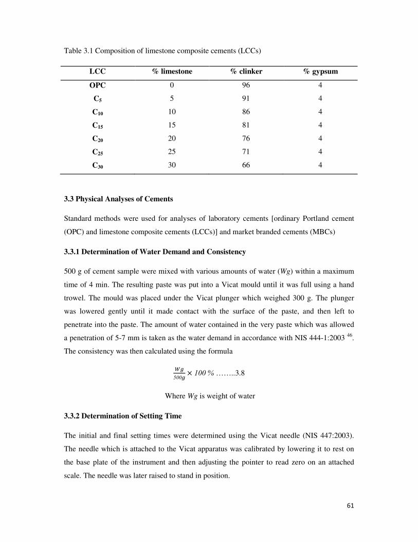
61
Table 3.1 Composition of limestone composite cements (LCCs)
LCC % limestone % clinker % gypsum
OPC 0 96 4
C5 5 91 4
C10 10 86 4
C15 15 81 4
C20 20 76 4
C25 25 71 4
C30 30 66 4
3.3 Physical Analyses of Cements
Standard methods were used for analyses of laboratory cements [ordinary Portland cement
(OPC) and limestone composite cements (LCCs)] and market branded cements (MBCs)
3.3.1 Determination of Water Demand and Consistency
500 g of cement sample were mixed with various amounts of water (Wg) within a maximum
time of 4 min. The resulting paste was put into a Vicat mould until it was full using a hand
trowel. The mould was placed under the Vicat plunger which weighed 300 g. The plunger
was lowered gently until it made contact with the surface of the paste, and then left to
penetrate into the paste. The amount of water contained in the very paste which was allowed
a penetration of 5-7 mm is taken as the water demand in accordance with NIS 444-1:2003 46
.
The consistency was then calculated using the formula
��
500�� 100 % ……..3.8
Where Wg is weight of water
3.3.2 Determination of Setting Time
The initial and final setting times were determined using the Vicat needle (NIS 447:2003).
The needle which is attached to the Vicat apparatus was calibrated by lowering it to rest on
the base plate of the instrument and then adjusting the pointer to read zero on an attached
scale. The needle was later raised to stand in position.
62
The cement paste which has gone through standard consistency test was transferred into an
open mould on the base plate of the Vicat instrument. The needle was released to penetrate
vertically into the paste. When penetration ceased, the scale on the Vicat instrument was read
and the time recorded as the initial setting time, T0.
The mould was later inverted, and the needle was attached with a ring, and allowed to rest on
the reverse face of the paste. The final setting time Tf was recorded as that time, starting from
onset of experiment when the ring failed to make a mark on the reverse surface.
3.3.3 Determination of Soundness
Cement paste of standard consistency was used to fill a Le Chatelier mould, which has two
indicator needles. After filling the mould, the distance (do) in millimeters, between the
needles was measured and recorded. The filled Le Chatelier mould was heated in boiling
water for 30 min., and after allowing to stay in a humidity cabinet for 24 hours, the soundness
was later determined by measuring the new distance (df) between the two needles. The
soundness was obtained by the difference, df – d0.
3.3.4 Determination of Cement Residue (Fineness) Using Sieve Method
100 g of cement sample were sieved through 45 µm, 90 µm and 180 µm sieves (BS 410). The
residues were expressed as percentage of the initial weight.
residue = ���� of residue
���� �� ���� ��� ��� 100 ……..3.9
3.3.5 Determination of Cement Surface Area Using Air Permeability Method
118 g of cement sample were carefully introduced into an air permeability cell which has a
filter paper on a disc with holes (1mm diameter) under it. The sample was covered by another
filter paper disc on its top to avoid loss of material by sticking onto the surface of a plunger.
The sample was compacted with a plunger which was inserted gently but firmly into the cell
until the plunger cap made contact with the cell.
The cell was inserted into the socket at the top of the manometer, and the stop cock of
the manometer was opened to adjust the manometer liquid to a lower etched line. The stop
cock was released and the timer started automatically and it stopped when the liquid reached
the upper etched line. The time for the liquid to move from the lower to the upper etched line
was recorded as ts.
63
Blaine (specific surface), or B is then calculated by the formular:
B = K√ts … 3.10
Where K is apparatus constant and B is in m2/kg
To determine K, a reference sample of known B was compacted and subjected to air
permeability test, and the time taken for the liquid to move from lower to higher etched line,
tsav was recorded. Thus K was obtained by the relationship;
K= B/ √tsav …3.11
3.3.6 Determination of Compressive Strength
Mortar consisting of one part by weight of cement (450g) and, three parts by weight of
standard sand (1350g) with water to cement ratio of 0.5 (225g of water) was produced. The
particle size distribution of standard sand used for the mortar production is shown in the
Table 3.1
Mortar production was by mechanical mixing as follows: Water was poured into a
mechanical mixer bowl and cement was added gently into the water. The mixer was
immediately started at low speed and the sand was steadily added during the next 30 seconds.
The mixer was switched to high speed and mixing continued for additional 30 seconds, after
which the mixer was turned off and mortar was allowed to rest for 90 seconds. During the
rest time, the sides of the mixer bowl were scrapped down to the bottom, before mixing
resumed at high speed for another 60 seconds. Table 3.2 shows the mixer speed during
mortar production.
The mortar samples produced were moulded immediately using a prismatic mould on a
jolting apparatus (NIS 446-2003)47
. With the mould firmly clamped to the jolting apparatus,
the prismatic test specimens were made in pairs for each mortar. The moulds were labeled
accordingly and stored for 24 hours in a humidity cabinet for the prisms to acquire strength
enough to be demoulded without risk of damage.
All demoulded prism specimens were water cured at 20 oC for various periods of time after
which, their compressive strengths (RF) were determined in MPa as follows:
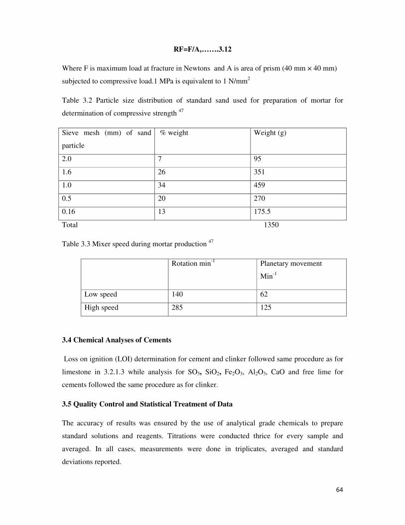
64
RF=F/A,…….3.12
Where F is maximum load at fracture in Newtons and A is area of prism (40 mm × 40 mm)
subjected to compressive load.1 MPa is equivalent to 1 N/mm2
Table 3.2 Particle size distribution of standard sand used for preparation of mortar for
determination of compressive strength 47
Sieve mesh (mm) of sand
particle
% weight Weight (g)
2.0 7 95
1.6 26 351
1.0 34 459
0.5 20 270
0.16 13 175.5
Total 1350
Table 3.3 Mixer speed during mortar production 47
Rotation min-1
Planetary movement
Min-1
Low speed 140 62
High speed 285 125
3.4 Chemical Analyses of Cements
Loss on ignition (LOI) determination for cement and clinker followed same procedure as for
limestone in 3.2.1.3 while analysis for SO3, SiO2, Fe2O3, Al2O3, CaO and free lime for
cements followed the same procedure as for clinker.
3.5 Quality Control and Statistical Treatment of Data
The accuracy of results was ensured by the use of analytical grade chemicals to prepare
standard solutions and reagents. Titrations were conducted thrice for every sample and
averaged. In all cases, measurements were done in triplicates, averaged and standard
deviations reported.

65
SPSS version 18.0 windows data editor software program was used in determining the
significance in variation of OPC, LCCs and MBCs.
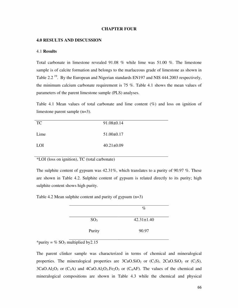
66
CHAPTER FOUR
4.0 RESULTS AND DISCUSSION
4.1 Results
Total carbonate in limestone revealed 91.08 % while lime was 51.00 %. The limestone
sample is of calcite formation and belongs to the marlaceous grade of limestone as shown in
Table 2.2 19
. By the European and Nigerian standards EN197 and NIS 444.2003 respectively,
the minimum calcium carbonate requirement is 75 %. Table 4.1 shows the mean values of
parameters of the parent limestone sample (PLS) analyses.
Table 4.1 Mean values of total carbonate and lime content (%) and loss on ignition of
limestone parent sample (n=3).
TC
Lime
LOI
91.08±0.14
51.00±0.17
40.21±0.09
*LOI (loss on ignition), TC (total carbonate)
The sulphite content of gypsum was 42.31%, which translates to a purity of 90.97 %. These
are shown in Table 4.2. Sulphite content of gypsum is related directly to its purity; high
sulphite content shows high purity.
Table 4.2 Mean sulphite content and purity of gypsum (n=3)
%
SO3 42.31±1.40
Purity 90.97
*purity = % SO3 multiplied by2.15
The parent clinker sample was characterized in terms of chemical and mineralogical
properties. The mineralogical properties are 3CaO.SiO2 or (C3S), 2CaO.SiO2 or (C2S),
3CaO.Al2O3 or (C3A) and 4CaO.Al2O3.Fe2O3 or (C4AF). The values of the chemical and
mineralogical compositions are shown in Table 4.3 while the chemical and physical
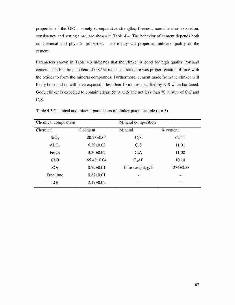
67
properties of the OPC, namely (compressive strengths, fineness, soundness or expansion,
consistency and setting time) are shown in Table 4.4. The behavior of cement depends both
on chemical and physical properties. These physical properties indicate quality of the
cement.
Parameters shown in Table 4.3 indicates that the clinker is good for high quality Portland
cement. The free lime content of 0.87 % indicates that there was proper reaction of lime with
the oxides to form the mineral compounds. Furthermore, cement made from the clinker will
likely be sound i.e will have expansion less than 10 mm as specified by NIS when hardened.
Good clinker is expected to contain atleast 55 % C3S and not less than 70 % sum of C2S and
C3S.
Table 4.3 Chemical and mineral parameters of clinker parent sample (n = 3)
Chemical composition Mineral composition
Chemical % content Mineral % content
SiO2 20.23±0.06 C3S 62.41
Al2O3 6.29±0.02 C2S 11.01
Fe2O3 3.30±0.02 C3A 11.08
CaO 65.48±0.04 C4AF 10.14
SO3 0.79±0.01 Litre weight, g/L 1274±0.58
Free lime 0.87±0.01 - -
LOI 2.17±0.02 - -
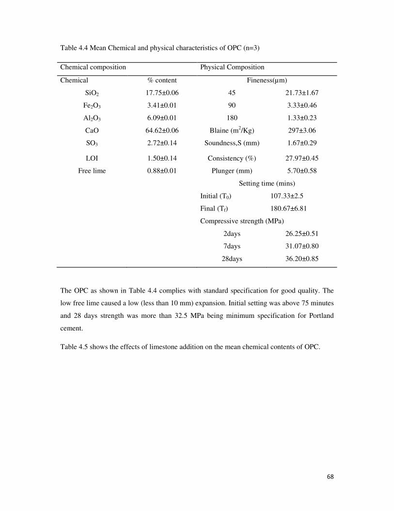
68
Table 4.4 Mean Chemical and physical characteristics of OPC (n=3)
Chemical composition Physical Composition
Chemical % content Fineness(µm)
SiO2 17.75±0.06 45 21.73±1.67
Fe2O3 3.41±0.01 90 3.33±0.46
Al2O3 6.09±0.01 180 1.33±0.23
CaO 64.62±0.06 Blaine (m2/Kg) 297±3.06
SO3 2.72±0.14 Soundness,S (mm) 1.67±0.29
LOI 1.50±0.14 Consistency (%) 27.97±0.45
Free lime 0.88±0.01 Plunger (mm) 5.70±0.58
Setting time (mins)
Initial (T0) 107.33±2.5
Final (Tf) 180.67±6.81
Compressive strength (MPa)
2days 26.25±0.51
7days 31.07±0.80
28days 36.20±0.85
The OPC as shown in Table 4.4 complies with standard specification for good quality. The
low free lime caused a low (less than 10 mm) expansion. Initial setting was above 75 minutes
and 28 days strength was more than 32.5 MPa being minimum specification for Portland
cement.
Table 4.5 shows the effects of limestone addition on the mean chemical contents of OPC.
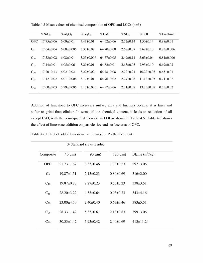
69
Table 4.5 Mean values of chemical composition of OPC and LCCs (n=3)
%SiO2 %Al2O3 %Fe2O3 %CaO %SO3 %LOI %Freelime
OPC 17.75±0.06 6.09±0.01 3.41±0.01 64.62±0.06 2.72±0.14 1.50±0.14 0.88±0.01
C5 17.64±0.04 6.08±0.006 3.37±0.02 64.70±0.08 2.68±0.07 3.69±0.10 0.83±0.006
C10 17.53±0.02 6.08±0.01 3.33±0.006 64.77±0.05 2.49±0.11 5.65±0.04 0.81±0.006
C15 17.44±0.01 6.05±0.06 3.29±0.01 64.82±0.01 2.63±0.03 7.95±0.10 0.69±0.02
C20 17.20±0.13 6.02±0.02 3.22±0.02 64.78±0.08 2.72±0.21 10.22±0.03 0.65±0.01
C25 17.12±0.02 6.01±0.006 3.17±0.01 64.96±0.02 2.27±0.08 11.12±0.05 0.71±0.02
C30 17.00±0.03 5.99±0.006 3.12±0.006 64.97±0.06 2.31±0.08 13.25±0.08 0.55±0.02
Addition of limestone to OPC increases surface area and fineness because it is finer and
softer to grind than clinker. In terms of the chemical content, it leads to reduction of all
except CaO, with the consequential increase in LOI as shown in Table 4.5. Table 4.6 shows
the effect of limestone addition on particle size and surface area of OPC.
Table 4.6 Effect of added limestone on fineness of Portland cement
% Standard sieve residue
Composite 45(µm) 90(µm) 180(µm) Blaine (m2/kg)
OPC 21.73±1.67 3.33±0.46 1.33±0.23 297±3.06
C5 19.87±1.51 2.13±0.23 0.80±0.69 316±2.00
C10 19.87±0.83 2.27±0.23 0.53±0.23 338±3.51
C15 28.20±3.22 4.33±0.64 0.93±0.23 343±4.16
C20 23.00±4.50 2.40±0.40 0.67±0.46 383±5.51
C25 28.33±1.42 5.33±0.61 2.13±0.83 399±3.06
C30 30.33±1.42 5.93±0.42 2.40±0.69 413±11.24
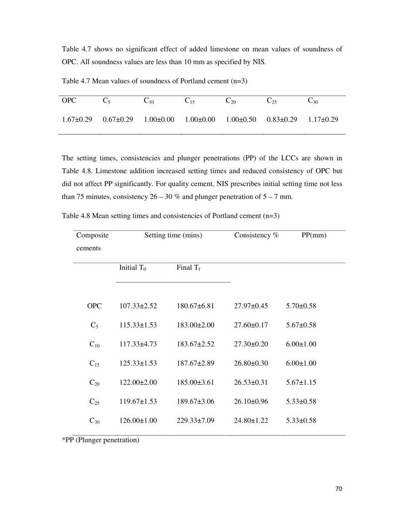
70
Table 4.7 shows no significant effect of added limestone on mean values of soundness of
OPC. All soundness values are less than 10 mm as specified by NIS.
Table 4.7 Mean values of soundness of Portland cement (n=3)
OPC C5 C10 C15 C20 C25 C30
1.67±0.29 0.67±0.29 1.00±0.00 1.00±0.00 1.00±0.50 0.83±0.29 1.17±0.29
The setting times, consistencies and plunger penetrations (PP) of the LCCs are shown in
Table 4.8. Limestone addition increased setting times and reduced consistency of OPC but
did not affect PP significantly. For quality cement, NIS prescribes initial setting time not less
than 75 minutes, consistency 26 – 30 % and plunger penetration of 5 – 7 mm.
Table 4.8 Mean setting times and consistencies of Portland cement (n=3)
Composite
cements
Setting time (mins) Consistency % PP(mm)
Initial T0 Final Tf
OPC 107.33±2.52 180.67±6.81 27.97±0.45 5.70±0.58
C5 115.33±1.53 183.00±2.00 27.60±0.17 5.67±0.58
C10 117.33±4.73 183.67±2.52 27.30±0.20 6.00±1.00
C15 125.33±1.53 187.67±2.89 26.80±0.30 6.00±1.00
C20 122.00±2.00 185.00±3.61 26.53±0.31 5.67±1.15
C25 119.67±1.53 189.67±3.06 26.10±0.96 5.33±0.58
C30 126.00±1.00 229.33±7.09 24.80±1.22 5.33±0.58
*PP (Plunger penetration)
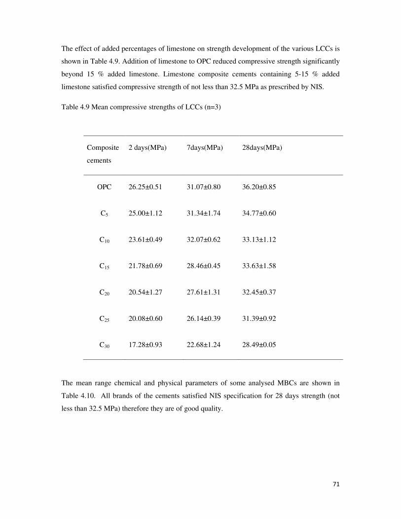
71
The effect of added percentages of limestone on strength development of the various LCCs is
shown in Table 4.9. Addition of limestone to OPC reduced compressive strength significantly
beyond 15 % added limestone. Limestone composite cements containing 5-15 % added
limestone satisfied compressive strength of not less than 32.5 MPa as prescribed by NIS.
Table 4.9 Mean compressive strengths of LCCs (n=3)
Composite
cements
2 days(MPa) 7days(MPa) 28days(MPa)
OPC 26.25±0.51 31.07±0.80 36.20±0.85
C5 25.00±1.12 31.34±1.74 34.77±0.60
C10 23.61±0.49 32.07±0.62 33.13±1.12
C15 21.78±0.69 28.46±0.45 33.63±1.58
C20 20.54±1.27 27.61±1.31 32.45±0.37
C25 20.08±0.60 26.14±0.39 31.39±0.92
C30 17.28±0.93 22.68±1.24 28.49±0.05
The mean range chemical and physical parameters of some analysed MBCs are shown in
Table 4.10. All brands of the cements satisfied NIS specification for 28 days strength (not
less than 32.5 MPa) therefore they are of good quality.
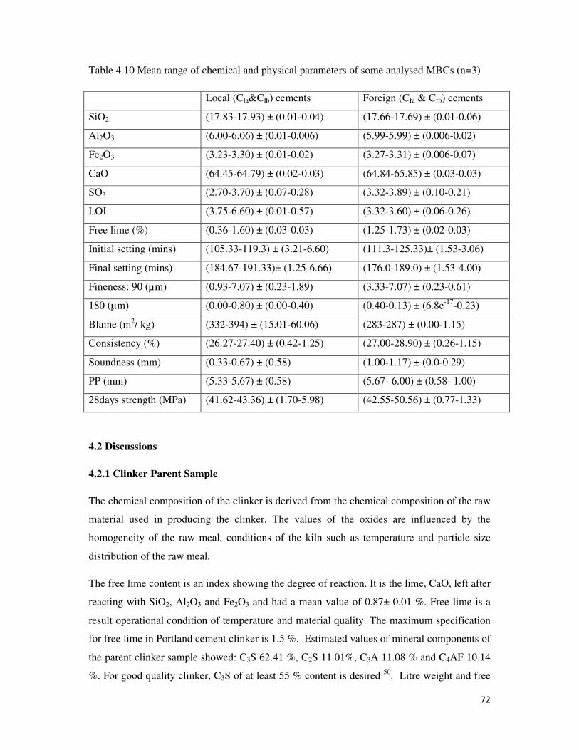
72
Table 4.10 Mean range of chemical and physical parameters of some analysed MBCs (n=3)
Local (Cla&Clb) cements Foreign (Cfa & Cfb) cements
SiO2 (17.83-17.93) ± (0.01-0.04) (17.66-17.69) ± (0.01-0.06)
Al2O3 (6.00-6.06) ± (0.01-0.006) (5.99-5.99) ± (0.006-0.02)
Fe2O3 (3.23-3.30) ± (0.01-0.02) (3.27-3.31) ± (0.006-0.07)
CaO (64.45-64.79) ± (0.02-0.03) (64.84-65.85) ± (0.03-0.03)
SO3 (2.70-3.70) ± (0.07-0.28) (3.32-3.89) ± (0.10-0.21)
LOI (3.75-6.60) ± (0.01-0.57) (3.32-3.60) ± (0.06-0.26)
Free lime (%) (0.36-1.60) ± (0.03-0.03) (1.25-1.73) ± (0.02-0.03)
Initial setting (mins) (105.33-119.3) ± (3.21-6.60) (111.3-125.33)± (1.53-3.06)
Final setting (mins) (184.67-191.33)± (1.25-6.66) (176.0-189.0) ± (1.53-4.00)
Fineness: 90 (µm) (0.93-7.07) ± (0.23-1.89) (3.33-7.07) ± (0.23-0.61)
180 (µm) (0.00-0.80) ± (0.00-0.40) (0.40-0.13) ± (6.8e-17
-0.23)
Blaine (m2/ kg) (332-394) ± (15.01-60.06) (283-287) ± (0.00-1.15)
Consistency (%) (26.27-27.40) ± (0.42-1.25) (27.00-28.90) ± (0.26-1.15)
Soundness (mm) (0.33-0.67) ± (0.58) (1.00-1.17) ± (0.0-0.29)
PP (mm) (5.33-5.67) ± (0.58) (5.67- 6.00) ± (0.58- 1.00)
28days strength (MPa) (41.62-43.36) ± (1.70-5.98) (42.55-50.56) ± (0.77-1.33)
4.2 Discussions
4.2.1 Clinker Parent Sample
The chemical composition of the clinker is derived from the chemical composition of the raw
material used in producing the clinker. The values of the oxides are influenced by the
homogeneity of the raw meal, conditions of the kiln such as temperature and particle size
distribution of the raw meal.
The free lime content is an index showing the degree of reaction. It is the lime, CaO, left after
reacting with SiO2, Al2O3 and Fe2O3 and had a mean value of 0.87± 0.01 %. Free lime is a
result operational condition of temperature and material quality. The maximum specification
for free lime in Portland cement clinker is 1.5 %. Estimated values of mineral components of
the parent clinker sample showed: C3S 62.41 %, C2S 11.01%, C3A 11.08 % and C4AF 10.14
%. For good quality clinker, C3S of at least 55 % content is desired 50
. Litre weight and free
73
lime are related in the sense that when free lime gets low the litre weight increases. This free
lime of 0.87 % and litre weight of 1274 g/L may suggest that the raw meal was subjected to
excessive heat. Although there is no specified limit for litre weight, it is however a good
operational control measure for free lime control.
4.2.2 Ordinary Portland Cement (OPC)
The chemical and physical properties of the laboratory OPC are shown in Table 4.4. The
chemical parameters SiO2, Al2O3, Fe2O3 and SO3 vary from those in clinker. The final
composition of the cement is as a result of the contribution of the gypsum in Table 4.2 to the
various oxides. 4 % gypsum increased SO3 from 0.79 % in clinker as seen in Table 4.1.3 to
2.72 % in cement as shown in Table 4.4. This value satisfies Standards specification of 2.5 to
3.5 % for SO3 in Portland cement 50
. The reduction in oxides, from clinker to OPC suggests
that gypsum contributes more SO3 than other oxides. Free lime was not affected by the
introduction of gypsum. The introduction of gypsum did not increase LOI but reduced it from
2.17 % in clinker to 1.50 % in OPC in Table 4.4. This is because gypsum unlike limestone
contributes lesser lime and this reduced LOI.
The particle sizes of the OPC ranging from 45 to 180 microns added up to 26.39 % as shown
in Table 4.4. This means that finer particle sizes added up to 73.61 %. This would have
increased if Blaine value were to be higher than 297m2/kg. Since OPC has no other additive
other than gypsum higher Blain would not be necessary since the strength giving compounds,
C3S and C2S are in their concentrated states. The particle size distribution effect is
appreciated by the rate of hydration which translates into strength development within two
days. The strength of cement concrete or mortar develops with the rate of hydration. More the
rate of hydration, the faster will the development of strength be. This is because the finer
cement particles hydrate faster because of greater surface area (Blaine) hence faster the
development of strength. Table 4.4 shows a mean compressive strength of 26.25 MPa at 2
days and 31.07 MPa at 7 days and 36.20 MPa at 28 days. Nigerian Standard for compressive
strength specifies a minimum of 16.0 MPa at 7 days and 32.5 MPa at 28 days 50
.
Nigerian Standards specification for Portland cement specifies maximum of 10 mm for
soundness, 26 to 30 % for consistency, 5 to 7 mm Vicat plunger penetration and minimum of
75 minutes for initial setting for Portland cement50
.
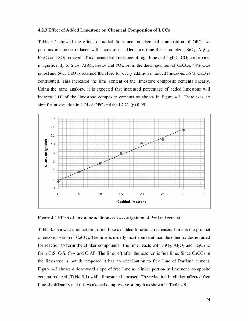
74
4.2.3 Effect of Added Limestone on Chemical Composition of LCCs
Table 4.5 showed the effect of added limestone on chemical composition of OPC. As
portions of clinker reduced with increase in added limestone the parameters; SiO2, Al2O3,
Fe2O3 and SO3 reduced. This means that limestone of high lime and high CaCO3 contributes
insignificantly to SiO2, Al2O3, Fe2O3 and SO3. From the decomposition of CaCO3, 44% CO2
is lost and 56% CaO is retained therefore for every addition in added limestone 56 % CaO is
contributed. This increased the lime content of the limestone composite cements linearly.
Using the same analogy, it is expected that increased percentage of added limestone will
increase LOI of the limestone composite cements as shown in figure 4.1. There was no
significant variation in LOI of OPC and the LCCs (p>0.05).
Figure 4.1 Effect of limestone addition on loss on ignition of Portland cement.
Table 4.5 showed a reduction in free lime as added limestone increased. Lime is the product
of decomposition of CaCO3. The lime is usually most abundant than the other oxides required
for reaction to form the clinker compounds. The lime reacts with SiO2, Al2O3 and Fe2O3 to
form C3S, C2S, C3A and C4AF. The lime left after the reaction is free lime. Since CaCO3 in
the limestone is not decomposed it has no contribution to free lime of Portland cement.
Figure 4.2 shows a downward slope of free lime as clinker portion in limestone composite
cement reduced (Table 3.1) while limestone increased. The reduction in clinker affected free
lime significantly and this weakened compressive strength as shown in Table 4.9.
0
2
4
6
8
10
12
14
16
0 5 10 15 20 25 30 35
% L
oss
on
ig
nit
ion
% added limestone

75
Figure 4.2 Plot of free lime against % added limestone in Portland cement
The sulphate which is in form of sulphite reduced with increased added limestone. This trend
was observed in two different investigations. Both of them concluded that although sulphite
decreased with increase in percent added limestone, it was not a linear relationship. This can
be observed in Table 4.5 as the reduction is not with every increase in added limestone as is
depicted in Fig 4.3. The NIS 444:2003 specifies 2.5 - 3.5 % SO3 for Portland cement. As
presented in Table 4.5 SO3 was satisfied from 5 to 20 % added limestone. Limestone addition
beyond 20 % affected SO3 significantly. Therefore the depletion of SO3 could lead to the
formation of carboaluminate which retards activity of C3A hence delaying setting as shown in
Table 4.8.
Figure 4.3 Plot of sulphite against % limestone in Portland cement
0
0.1
0.2
0.3
0.4
0.5
0.6
0.7
0.8
0.9
1
0 5 10 15 20 25 30 35
% F
ree
lim
e
% Added limestone
0
0.5
1
1.5
2
2.5
3
0 5 10 15 20 25 30 35
% S
O3
% Added limestone
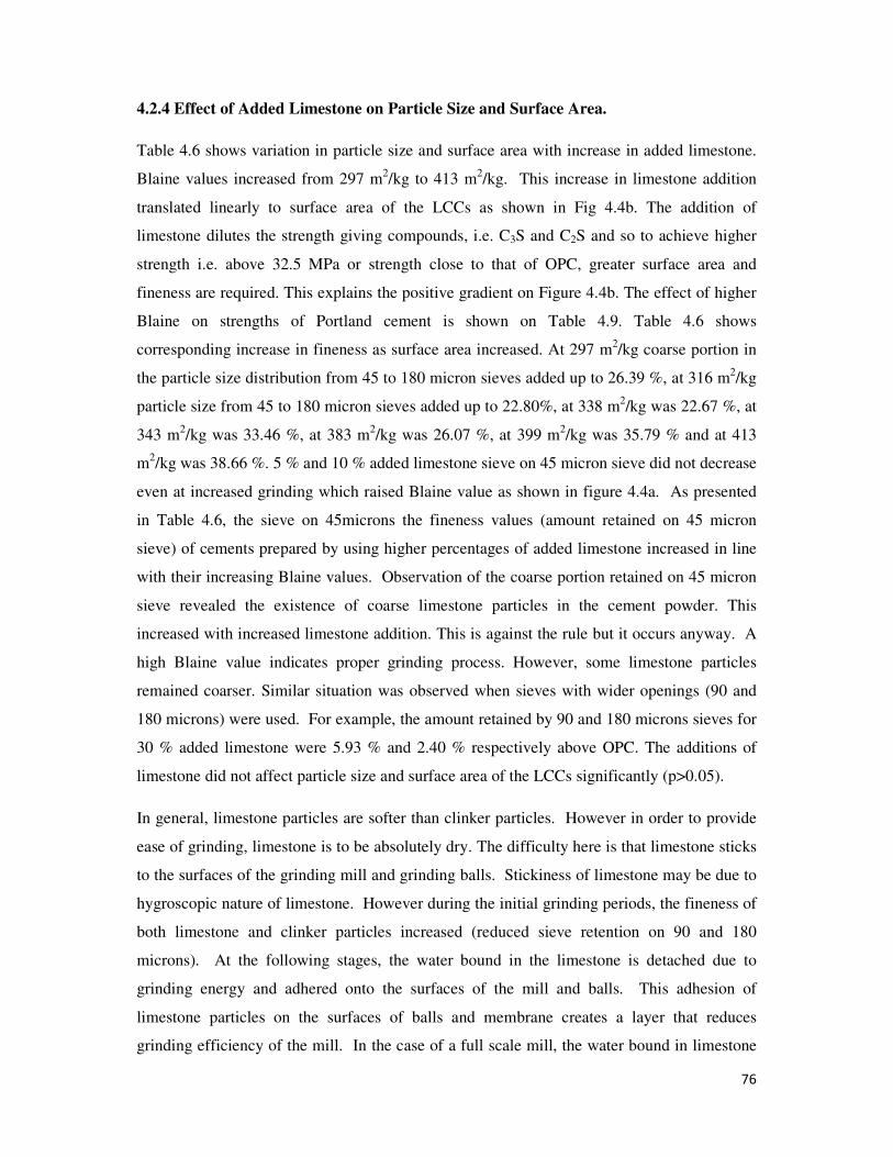
76
4.2.4 Effect of Added Limestone on Particle Size and Surface Area.
Table 4.6 shows variation in particle size and surface area with increase in added limestone.
Blaine values increased from 297 m2/kg to 413 m
2/kg. This increase in limestone addition
translated linearly to surface area of the LCCs as shown in Fig 4.4b. The addition of
limestone dilutes the strength giving compounds, i.e. C3S and C2S and so to achieve higher
strength i.e. above 32.5 MPa or strength close to that of OPC, greater surface area and
fineness are required. This explains the positive gradient on Figure 4.4b. The effect of higher
Blaine on strengths of Portland cement is shown on Table 4.9. Table 4.6 shows
corresponding increase in fineness as surface area increased. At 297 m2/kg coarse portion in
the particle size distribution from 45 to 180 micron sieves added up to 26.39 %, at 316 m2/kg
particle size from 45 to 180 micron sieves added up to 22.80%, at 338 m2/kg was 22.67 %, at
343 m2/kg was 33.46 %, at 383 m
2/kg was 26.07 %, at 399 m
2/kg was 35.79 % and at 413
m2/kg was 38.66 %. 5 % and 10 % added limestone sieve on 45 micron sieve did not decrease
even at increased grinding which raised Blaine value as shown in figure 4.4a. As presented
in Table 4.6, the sieve on 45microns the fineness values (amount retained on 45 micron
sieve) of cements prepared by using higher percentages of added limestone increased in line
with their increasing Blaine values. Observation of the coarse portion retained on 45 micron
sieve revealed the existence of coarse limestone particles in the cement powder. This
increased with increased limestone addition. This is against the rule but it occurs anyway. A
high Blaine value indicates proper grinding process. However, some limestone particles
remained coarser. Similar situation was observed when sieves with wider openings (90 and
180 microns) were used. For example, the amount retained by 90 and 180 microns sieves for
30 % added limestone were 5.93 % and 2.40 % respectively above OPC. The additions of
limestone did not affect particle size and surface area of the LCCs significantly (p>0.05).
In general, limestone particles are softer than clinker particles. However in order to provide
ease of grinding, limestone is to be absolutely dry. The difficulty here is that limestone sticks
to the surfaces of the grinding mill and grinding balls. Stickiness of limestone may be due to
hygroscopic nature of limestone. However during the initial grinding periods, the fineness of
both limestone and clinker particles increased (reduced sieve retention on 90 and 180
microns). At the following stages, the water bound in the limestone is detached due to
grinding energy and adhered onto the surfaces of the mill and balls. This adhesion of
limestone particles on the surfaces of balls and membrane creates a layer that reduces
grinding efficiency of the mill. In the case of a full scale mill, the water bound in limestone
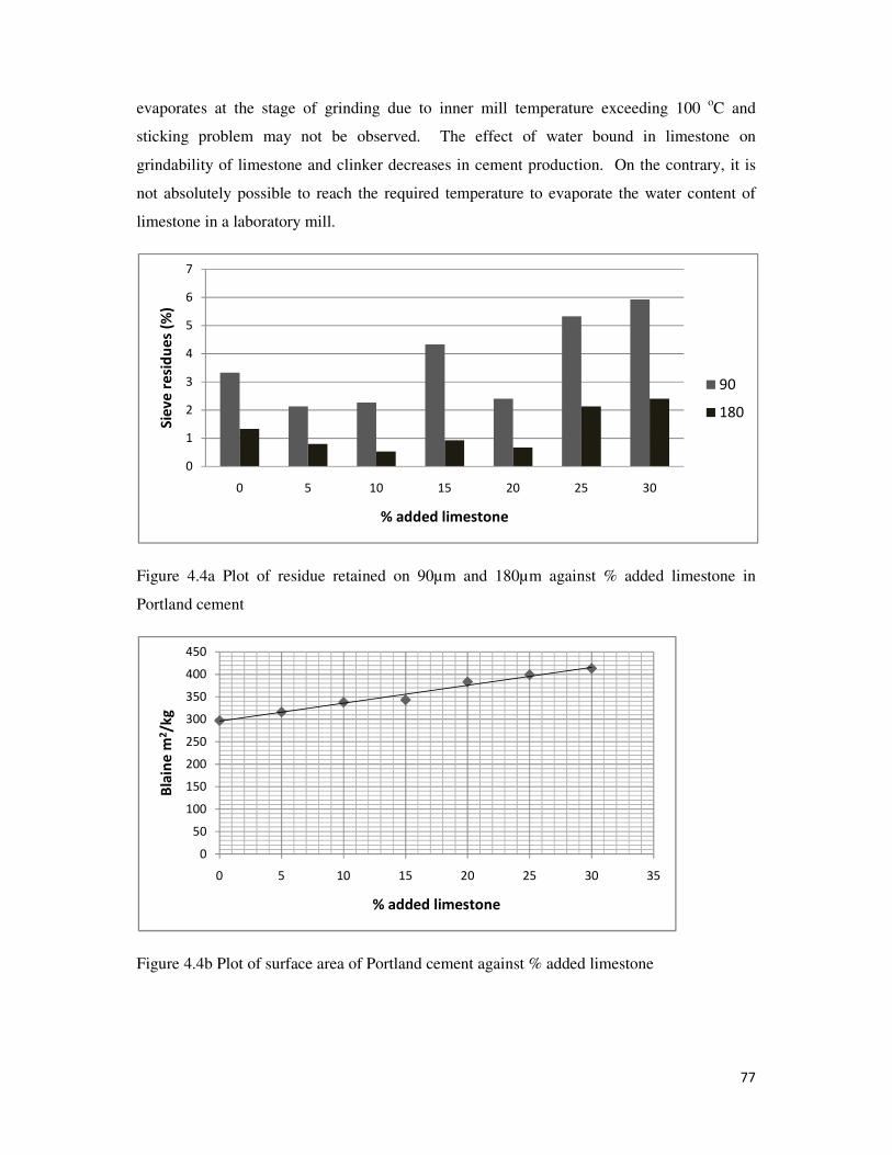
77
evaporates at the stage of grinding due to inner mill temperature exceeding 100 oC and
sticking problem may not be observed. The effect of water bound in limestone on
grindability of limestone and clinker decreases in cement production. On the contrary, it is
not absolutely possible to reach the required temperature to evaporate the water content of
limestone in a laboratory mill.
Figure 4.4a Plot of residue retained on 90µm and 180µm against % added limestone in
Portland cement
Figure 4.4b Plot of surface area of Portland cement against % added limestone
0
1
2
3
4
5
6
7
0 5 10 15 20 25 30
Sie
ve
re
sid
ue
s (%
)
% added limestone
90
180
0
50
100
150
200
250
300
350
400
450
0 5 10 15 20 25 30 35
Bla
ine
m2/k
g
% added limestone
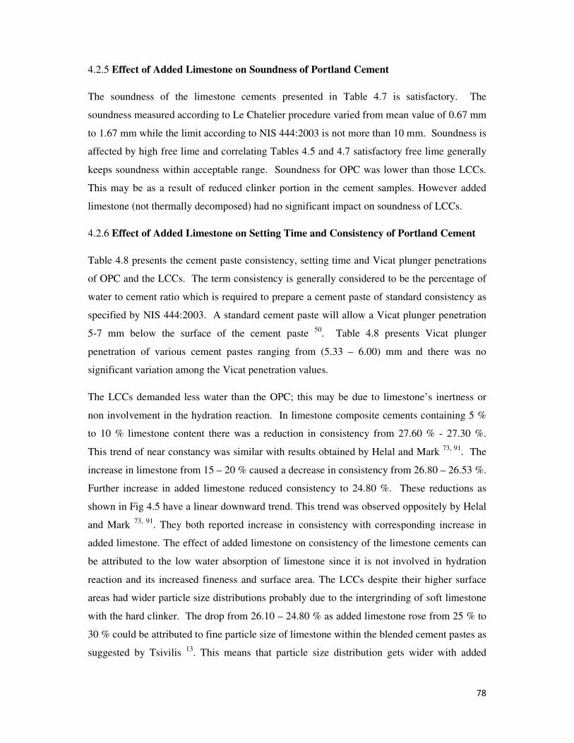
78
4.2.5 Effect of Added Limestone on Soundness of Portland Cement
The soundness of the limestone cements presented in Table 4.7 is satisfactory. The
soundness measured according to Le Chatelier procedure varied from mean value of 0.67 mm
to 1.67 mm while the limit according to NIS 444:2003 is not more than 10 mm. Soundness is
affected by high free lime and correlating Tables 4.5 and 4.7 satisfactory free lime generally
keeps soundness within acceptable range. Soundness for OPC was lower than those LCCs.
This may be as a result of reduced clinker portion in the cement samples. However added
limestone (not thermally decomposed) had no significant impact on soundness of LCCs.
4.2.6 Effect of Added Limestone on Setting Time and Consistency of Portland Cement
Table 4.8 presents the cement paste consistency, setting time and Vicat plunger penetrations
of OPC and the LCCs. The term consistency is generally considered to be the percentage of
water to cement ratio which is required to prepare a cement paste of standard consistency as
specified by NIS 444:2003. A standard cement paste will allow a Vicat plunger penetration
5-7 mm below the surface of the cement paste 50
. Table 4.8 presents Vicat plunger
penetration of various cement pastes ranging from (5.33 – 6.00) mm and there was no
significant variation among the Vicat penetration values.
The LCCs demanded less water than the OPC; this may be due to limestone’s inertness or
non involvement in the hydration reaction. In limestone composite cements containing 5 %
to 10 % limestone content there was a reduction in consistency from 27.60 % - 27.30 %.
This trend of near constancy was similar with results obtained by Helal and Mark 73, 91
. The
increase in limestone from 15 – 20 % caused a decrease in consistency from 26.80 – 26.53 %.
Further increase in added limestone reduced consistency to 24.80 %. These reductions as
shown in Fig 4.5 have a linear downward trend. This trend was observed oppositely by Helal
and Mark 73, 91
. They both reported increase in consistency with corresponding increase in
added limestone. The effect of added limestone on consistency of the limestone cements can
be attributed to the low water absorption of limestone since it is not involved in hydration
reaction and its increased fineness and surface area. The LCCs despite their higher surface
areas had wider particle size distributions probably due to the intergrinding of soft limestone
with the hard clinker. The drop from 26.10 – 24.80 % as added limestone rose from 25 % to
30 % could be attributed to fine particle size of limestone within the blended cement pastes as
suggested by Tsivilis 13
. This means that particle size distribution gets wider with added
79
limestone and 30% added limestone gave the widest particle size distribution and its particle
size required the least percentage of water for hydration.
Setting time is affected by (i) cement fineness and (ii) water to cement ratio (consistency).
Table 4.8 presents the consistencies and setting times of cement pastes as added limestone
increased. Table 4.8 shows that the blended cement paste had delays in initial setting times
more than OPC. The reactions involved in setting of cement are the hydration of C3A and
calcium silicates which change into their colloidal gels. At the same time, some calcium
hydroxide and aluminum hydroxide are formed as precipitates due to hydrolysis. Calcium
hydroxide binds the particles of calcium silicate together while aluminum hydroxide fills the
interstices rendering the mass impervious. These six reactions are responsible for initial
setting 92
(1) 3CaO. Al2O3 + 6H2O → 3CaO . Al2O3 .6H2O
Tricalcium Aluminate hydrated colloidal gel of tricalcium aluminate
(2) 3CaO SiO2 + H2O → Ca(OH)2 + 2CaO. SiO2
Tricalcium silicate Dicalcium silicate
(3) 2CaO. SiO2 + xH2O → 2CaO. SiO2. xH2O
Dicalcium silicate hydrated colloidal gel of dicalcium silicate
(4) 3CaO. Al2O3 + 6H2O → 3Ca(OH)2 + 2Al(OH)3
Tricalcium Aluminate
(5) 4CaO. Al2O3. Fe2O3 + 6H2O → 3CaO. Al2O3 6H2O + CaO. Fe2O3
Tetracalcium aluminoferrite Hydrated colloidal gel of tricalcium aluminate.
(6) 3CaO. Al2O3 + 3CaSO4 + 31H2O → 3CaO. Al2O3. 3CaSO4. 31H2O
Calcium sulphoaluminate or Ettringite
As shown in Table 4.5, increase in Limestone depleted SO3. It is expected that setting time
will be hastened. This was the trend observed by Mark 91
and this was contrary to trend
shown in Table 4.8. Fig 4.6 shows no clear trend in how added limestone affects initial
setting time of LCCs. From the observations in separate determinations, there was a non
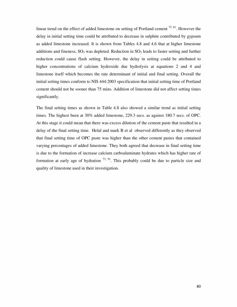
80
linear trend on the effect of added limestone on setting of Portland cement 75, 81
. However the
delay in initial setting time could be attributed to decrease in sulphite contributed by gypsum
as added limestone increased. It is shown from Tables 4.8 and 4.6 that at higher limestone
additions and fineness, SO3 was depleted. Reduction in SO3 leads to faster setting and further
reduction could cause flash setting. However, the delay in setting could be attributed to
higher concentrations of calcium hydroxide due hydrolysis at equations 2 and 4 and
limestone itself which becomes the rate determinant of initial and final setting. Overall the
initial setting times conform to NIS 444:2003 specification that initial setting time of Portland
cement should not be sooner than 75 mins. Addition of limestone did not affect setting times
significantly.
The final setting times as shown in Table 4.8 also showed a similar trend as initial setting
times. The highest been at 30% added limestone, 229.3 secs. as against 180.7 secs. of OPC.
At this stage it could mean that there was excess dilution of the cement paste that resulted in a
delay of the final setting time. Helal and mark B et al observed differently as they observed
that final setting time of OPC paste was higher than the other cement pastes that contained
varying percentages of added limestone. They both agreed that decrease in final setting time
is due to the formation of increase calcium carboaluminate hydrates which has higher rate of
formation at early age of hydration 73, 91
. This probably could be due to particle size and
quality of limestone used in their investigation.
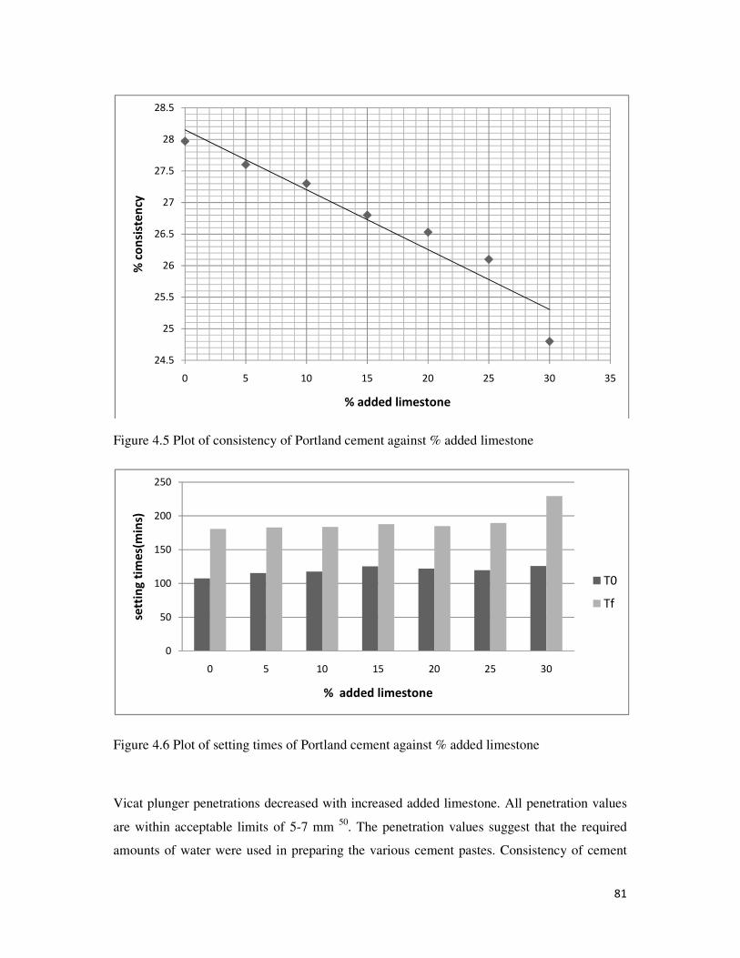
81
Figure 4.5 Plot of consistency of Portland cement against % added limestone
Figure 4.6 Plot of setting times of Portland cement against % added limestone
Vicat plunger penetrations decreased with increased added limestone. All penetration values
are within acceptable limits of 5-7 mm 50
. The penetration values suggest that the required
amounts of water were used in preparing the various cement pastes. Consistency of cement
24.5
25
25.5
26
26.5
27
27.5
28
28.5
0 5 10 15 20 25 30 35
% c
on
sist
en
cy
% added limestone
0
50
100
150
200
250
0 5 10 15 20 25 30
sett
ing
tim
es(
min
s)
% added limestone
T0
Tf
82
paste is expected to be less than 30 % since water affects setting time. The penetration values
at C25 and C30 are acceptable though, the consistencies suggest that the pastes were diluted
with excess water. The suspected over dilution might have also contributed to the prolonged
setting times of C30.
4.2.7 Effect of Added Limestone on Strength Development of Portland Cement.
The compressive strengths of OPC and LCCs are presented in Table 4.9. No significant effect
of added limestone on compressive strength was observed at 5% added limestone on all days
of curing. The strengths of all LCCs showed good early strength development within 7 days.
This is due to enhanced surface area and increased fineness. The strength of cement concrete
or mortar develops with the rate of hydration. The strength attained is a direct result of the
rate of hydration. A greater rate of hydration will produce higher strength. Standards
Organization of Nigeria does not specify minimum strength for 2 days but all 2 days strength
development are higher than 16 MPa minimum for 7 days. However, limestone addition
decreased the 28 days strengths. Bars illustrating strength gain at different percentages of
added limestone are given in Fig 4.10. Early age strength gain was higher for C5. The reason
for early age strength enhancement may be attributed to the nucleus forming effect of calcium
carbonate, CaCO3, particles for calcium hydroxide crystals at low concentration and
accelerating effect of limestone to the formation of calcium silicate hydrates, CSH 74
. At the
same time, limestone particles contribute to the strength development by forming
carboaluminate and by reducing the pore size of interstices thereby acting as inert filler 72, 74 &
80. However compressive strengths decreased with increased limestone addition in the long
term (28 days). It seems that beyond 2 to 3 days, calcium hydroxide concentrations decrease.
This may explain the drop in strength development with increase in added limestone
percentage for all the days of curing. Infact added limestone affected strength at 28 days
significantly beyond 15 % added limestone as shown in figure 4.8. By NIS 444:2003
specification, OPC satisfied 16.0 MPa for 7 days and 32.5 MPa for 28 days for Portland
cement.
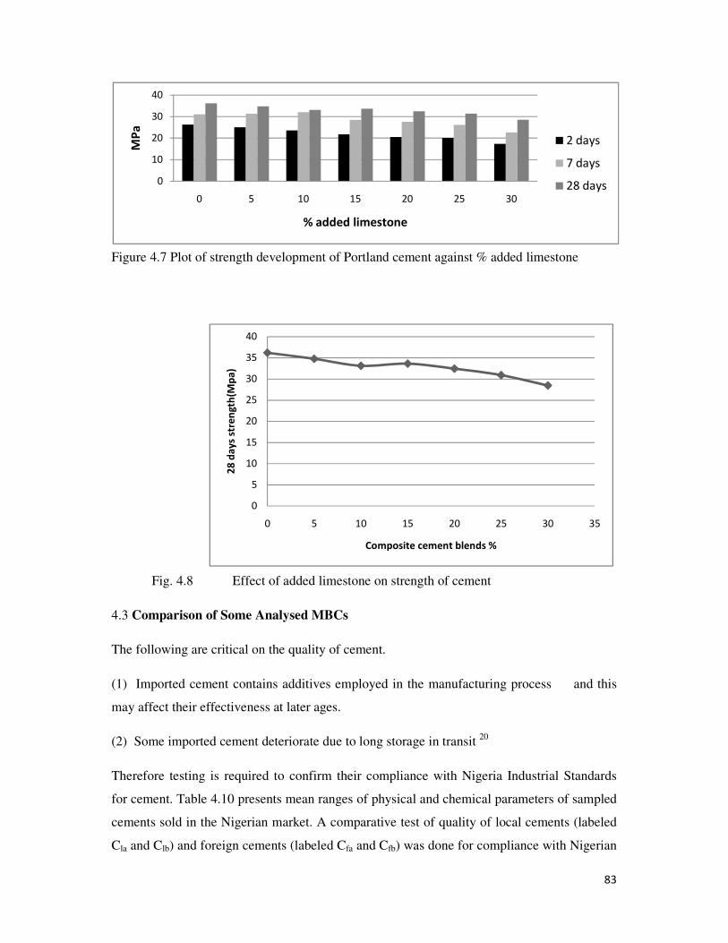
83
Figure 4.7 Plot of strength development of Portland cement against % added limestone
Fig. 4.8 Effect of added limestone on strength of cement
4.3 Comparison of Some Analysed MBCs
The following are critical on the quality of cement.
(1) Imported cement contains additives employed in the manufacturing process and this
may affect their effectiveness at later ages.
(2) Some imported cement deteriorate due to long storage in transit 20
Therefore testing is required to confirm their compliance with Nigeria Industrial Standards
for cement. Table 4.10 presents mean ranges of physical and chemical parameters of sampled
cements sold in the Nigerian market. A comparative test of quality of local cements (labeled
Cla and Clb) and foreign cements (labeled Cfa and Cfb) was done for compliance with Nigerian
0
10
20
30
40
0 5 10 15 20 25 30
MP
a
% added limestone
2 days
7 days
28 days
0
5
10
15
20
25
30
35
40
0 5 10 15 20 25 30 35
28
da
ys
stre
ng
th(M
pa
)
Composite cement blends %

84
Industrial Standards for cement. The range of loss on ignition (3.75 – 6.60) % for the local
brands of cement suggests that those cements samples were not OPC or type I cement. If
limestone were added to OPC it may have been between 5 to 10 % when compared with
Table 4.5. The loss on ignition of the foreign cement (3.32 -3.60) % suggest that the cements
most likely are Type I. this argument could be justified by the Blaine values of the foreign
cements. The Blaine range (283 – 287) m2/kg of the foreign cements are lower than those of
the local cements (332 – 394) m2/ kg but still have comparable if not higher 28 days
compressive strength. A higher Blaine indicates more proper grinding process. The higher
Blaines in the local cements could mean that higher surface area or greater grinding was
required to compensate for the dilution of C3S and C2S in OPC. This explains the high
strength in the foreign cement with lower Blaines.
Free lime values of both the foreign and local cement brands satisfied NIS 444:2003
specification of 2.5 % maximum limit for cements. The free lime values show optimum
condition for CaO to react with SiO2, Al2O3 and Fe2O3. Further more such clinker most likely
will not expand more than 10 mm as specified by NIS 444.2003.
Initial setting time of the local cement brands (105.3 – 119.3 mins.) were shorter than those
of the foreign cements (125.3 – 111.3 mins.). There is a relationship between SO3 and setting
of cement. A higher SO3 will delay in setting and vice versa. The wider range of SO3 in the
foreign cements is responsible for greater delays in setting than they are in the local cements.
All initial setting times are satisfactory as they satisfy NIS 444:2003 specification not sooner
than 75 minutes for Portland cement.
Obviously there was greater grinding in the local cements than the foreign cements. The
residue range on 90 µm for the local cements (0.93 – 7.07 %) as compared to foreign cements
(3.33 – 7.07 %) suggest that there was greater grinding process in the local cements.
Although residue when followed by higher surface area (Blaine) in the local cements, it
becomes obvious that it was necessary to compensate for adulteration of C3S and C2S. The
adulterated C2S and C3S require greater grinding to increase their surface area to hydration to
have high compressive strength. Residue on 90 µm of the local cements was 7.07 %. It is
characteristic of soft materials when interground with clinker. The soft material was retained
more even though it was subjected to greater grinding. This may be that the additive adhered
to the surface of the grinding membranes which in turn may have reduced grinding
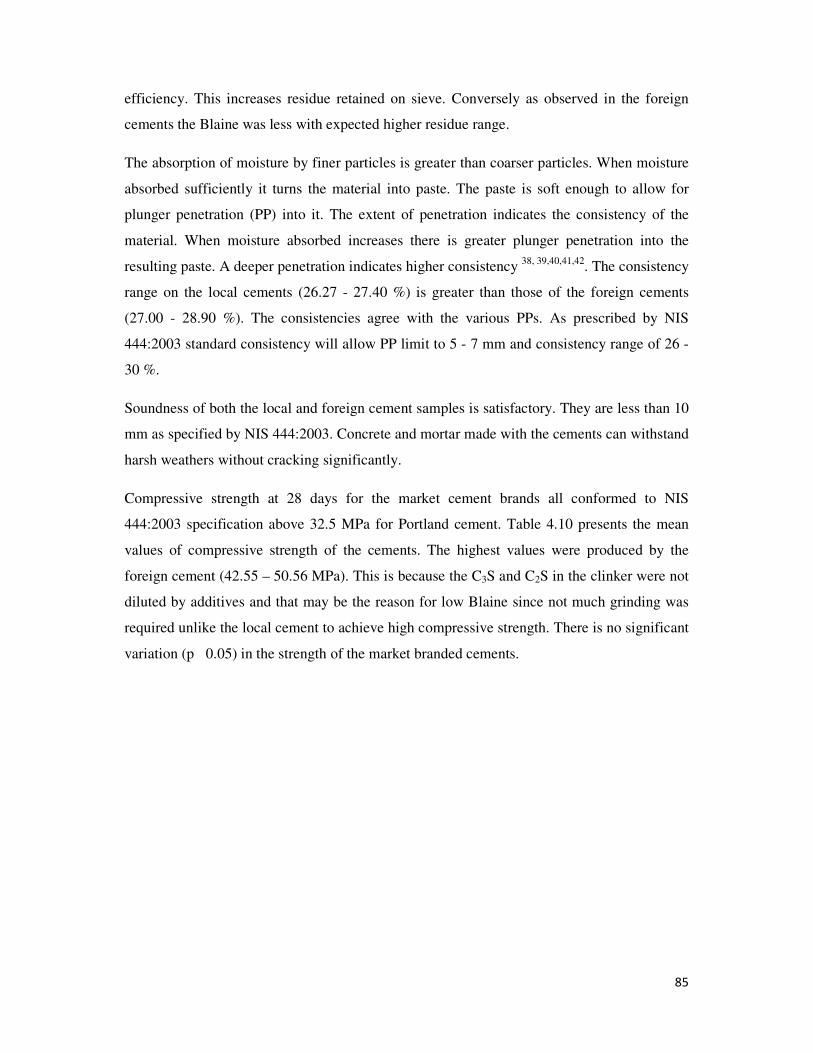
85
efficiency. This increases residue retained on sieve. Conversely as observed in the foreign
cements the Blaine was less with expected higher residue range.
The absorption of moisture by finer particles is greater than coarser particles. When moisture
absorbed sufficiently it turns the material into paste. The paste is soft enough to allow for
plunger penetration (PP) into it. The extent of penetration indicates the consistency of the
material. When moisture absorbed increases there is greater plunger penetration into the
resulting paste. A deeper penetration indicates higher consistency 38, 39,40,41,42
. The consistency
range on the local cements (26.27 - 27.40 %) is greater than those of the foreign cements
(27.00 - 28.90 %). The consistencies agree with the various PPs. As prescribed by NIS
444:2003 standard consistency will allow PP limit to 5 - 7 mm and consistency range of 26 -
30 %.
Soundness of both the local and foreign cement samples is satisfactory. They are less than 10
mm as specified by NIS 444:2003. Concrete and mortar made with the cements can withstand
harsh weathers without cracking significantly.
Compressive strength at 28 days for the market cement brands all conformed to NIS
444:2003 specification above 32.5 MPa for Portland cement. Table 4.10 presents the mean
values of compressive strength of the cements. The highest values were produced by the
foreign cement (42.55 – 50.56 MPa). This is because the C3S and C2S in the clinker were not
diluted by additives and that may be the reason for low Blaine since not much grinding was
required unlike the local cement to achieve high compressive strength. There is no significant
variation (p˃0.05) in the strength of the market branded cements.
86
4.4 CONCLUSION
Limestone addition to ordinary Portland cement caused variations in the properties of the
OPC. However, the limestone composite cements (LCCs) with not more than15 % limestone
content compared favourably (p>0.05) with OPC. Further addition of limestone lowered the
quality of the LCCs (p<0.05) and made them unsuitable for high durable concrete works.
Therefore the range of 5 – 15 % was optimum for good quality limestone composite cement,
good enough to be used just as OPC in concrete and construction works. With this range 28
day compressive strength was good and satisfied NIS requirement for good Portland cement.
Quality parameters: setting time, soundness, sulphite and strength were good. These range of
LCCs, 5 – 15 % limestone content, compared favourably (p>0.05) with various analysed
brands of Portland cements obtained from Nigerian markets.
Composite cements that contained 20 - 30 % showed significant variation (p<0.05) in 28
days compressive strength and are unfit for high durable structures but can serve for masonry
works like plaster for walls.
4.5 Recommendations
1 Limestone content in limestone composite cement should not exceed 15%
2 Limestone composite cements containing not more than 15 % could be used in areas
where OPC is required
3 Since the LCCs (5 - 15 %) are comparable (p>0.05) with OPC, they can be used as
cheaper alternatives to minimize cost of construction works.
4 Consequently, cement manufacturers could be encouraged to produce this range of
LCCs to bring down cost of building.
4.6 Contribution to Knowledge
1 The optimum limestone content of limestone composite cement was found to be 5 –
15 %
2 This range of LCCs compared favourably (p>0.05) in quality with OPC
3 Beyond this range, the LCCs were found unfit for high durable civil and concrete
works, but could be used for masonry works
87
REFERENCES
1. Lea, F.M (1970), Chemistry of Cement and Concrete. Edward Arnold Ltd., London
3rd
ed., p. 250
2. Cement (2009).Encyclopedia Britannica. Encyclopedia Britannica 2009 Student and
Home Edition. Chicago
3. Li Yong Yan (2004), China’s way forward paved in cement. Asia Times, January 7th
2004, http://www.atimes.com
4. Ian, F. and Abidoye, T., (2009), Nigerian cement industry set period of major growth;
Ultimate guide to business, trade and investment in Nigeria.
http://www.csls.firstcitygroup.com
5. National Emissions Assessment Agency (2007), China now No.1 in CO2 emission,
USA in second position, CO2 emissions in China. http://www.eia.gov. Retrieved 20
July 2007
6. lizabeth, R., (2007), Cement industry is at centre of climate change debate, New York
Times. 26 October 2007
7. John Wilson, W and Ding, Y.C., (2007), Comprehensive report on pozzolanic
admixtures. The cement industry, market and economic trends and major companies
operating in the Far East, with reference to Pagan Island. Document of the department
of public lands, Northern Mariana Islands, pp. 4-15
8. European Committee for Standardization, Cement: Composition, Specifications and
Conformity Criteria, EN 197-1, 2000.
9. Hooton, R.D and Michael, D.A.,(2002) The use of limestone in Portland cements:
Effect on thaumasite form of sulphate attack. Portland Cement Association 2658, pp.
3-9
10. Z’hor, G., Resheidat, M., Houari, H. and Toumi, B., (2008), Optimal criteria of
Algerian blended cement using limestone fines; Journal of Civil Engineering and
Management. 14 (4): 269-275
11. Hawkins, P., Tennis P.D. and Detwiller, R.J., (2003). The use of limestone in Portland
cement: A state of the art review. Portland Cement Association, Skokie, Illinois,
USA, pp. 19-24
12. Minerals in Ghana (2007). A Report of the Ministry of Trade and Industry, Ghana.
88
13. Tsivilis S., Batis G., Chaniotakis E., Grigoriadis G. and Theodossis D., (2000).
Properties and behavior of limestone cement concrete and mortar. Cement and
Concrete Research. 30 (10): 1679-1683
14. Traditional Mortars, http:// www.rumford.com/articlemortar.html
15. Taylor, H.F.W (1964) The Chemistry of Cements, vol.1, Academic Press, London,
pp.1-48
16. Nigeria Investment Promotion Commission (2010). Opportunity in mining and
processing of limestone, trade invest Nigeria.
17. Alison Madueke, D., (2009). Opportunity in Nigerias minerals sector; Ministry of
Mines and Steel Development, 2009.
18. Non Metallic Minerals and Industrial Materials, http://www.
Onlinenigeria.com/geology
19. Blue Circle (1978), Manual for West African Portland Cement Company, Shagamu,
Ogun State, Nigeria. pp. 14-24
20. Agbazue, V.E (1992). A Guide to Cement Industry Quality Control in Nigeria. Fourth
Dimension Publishers, Enugu, Nigeria, pp.11-51
21. Duda, W.H (1985), Cement Data Book vol.1,International Process Engineering in the
Cement industry, 3rd
ed.,Bauverlag GmbH.Wiesbaden und Berlin, pp.1-38
22. Grim, R.E (1953), Clay Mineralogy, McGraw Hill. New York, p. 311
23. Ministry of Solid Minerals Development (2000). An inventory of solid mineral
potentials of Nigeria. Prospectus for investors, p.15.
24. US Department of Transport, Federal Highway Administration Washington D.C.,
(1990), Portland cement concrete materials manual
25. American Concrete Pipe Association (1988), Concrete pipe handbook
26. United States Bureau of Reclamation (1975), Concrete manual.
27. Bogue, R.H (1929), Calculation of the Components in Portland Cement, Industry
Engineering Chemistry (1st Edition), Reinhold Publishing Corp., New York, pp.192-
197
89
28. ASTM Designation C 150-70; Standard specification for Portland cement, ASTM
Philadelphia, USA
29. Tsuboi, T. and Ogawa, T., (1978), Microscopic Studies of Clinker for Evaluating the
Sintering Process. Portland Cement Association,USA, pp. 27-33.
30. Taylor, H.F.W (1997), Cement Chemistry (2nd
Edition), Thomas Telford Publishing,
London.
31. Duda, W.H (1977), Cement Data Book Vol.2: Electrical Engineering Automation,
Storage, Transport and Dispatch (1st Edition), Bauverlag GmbH.Wiesbaden und
Berlin, pp.284-294
32. Javed, B., MacGregor, M., and Steven H.,(2004), Innovations in Portland Cement
Manufacturing, SP400, Portland Cement Association, Skokie Illinois, USA
33. Kolovos, K., Tsivilis, S. and Kakali, G., (2001), The effect of foreign ions on the
reactivity of the CaO-SiO2-Al2O3-Fe2O3 system: Part 1,Cement and Concrete
Research 31(3):425-429
34. Kolovos, K., Tsivilis, S. and Kakali, G., (2002), The effect of foreign ions on
reactivity of the CaO-SiO2-Al2O3-Fe2O3 system: Part 2,Cement and Concrete
Research 3: 463-469
35. Kakali, G., Tsivilis, S., Kolovos, K., Choupa, K., Perraki, T., Perraki, M., Stamatakis,
M. and Vasilatos, C., (2003), Use of secondary mineralizing raw materials in cement
production. Materials Letters 57: 3117-3123. http://www. Elsevier.com. Retrieved 22
September 2002.
36. Kakali, G., Tsivilis, S., Kolovos, K., Voglis, N., Aivaliotis, J., Perraki, T.,
Passialakon, E. and Stamatakis, M., (2005), Use Of secondary mineralizing raw
materials in cement production. A case study of a wolfranite - stibnite ore. Cement
and Concrete Composites 27: 155-161
37. Schindler, A.K. and Folliard, K.G., (2003), Influence of supplementary cementing
materials on the heat of hydration of concrete. Advanced in Cement and Concrete 9:
10-14
38. Naceri, A., Chikouche, H.M., Grosseau, P., (2009), Physicochemical characteristics of
cement manufactured with artificial pozzolan, World Academy of Science,
Engineering and Technology 28: 41-43
39. Caijun, S., (2001), An overview on the activation of reactivity of natural pozzolans.
Canadian Journal of Civil Engineering 28: 778-786
90
40. Standard Method of Test for Autoclave Expansion of Portland Cement, ASTM C 151-
54, American Standards Association,1954
41. Neville, A.M., (1996), Properties of Concrete. 4th
ed, Pearson Prentice Hall, pp. 269-
279
42. Mindess, S., and Young, J.F, (1981). Concrete. Englewood Cliffs, N.J. Prentice
Hall, Inc., pp. 567-572
43. Chang, P.K.,(2004). An approach to optimizing mix designs for properties of high
performance concrete, Cement and Concrete Research 34, 623-629
44. Ferraris, C.F, William, G.A, Aviles A.I, Robin, H. and MacDonald B.S (2005),
Certification of standard reference material, National Institute of Standards and
Technology, pp. 7-15
45. Klemm, W.A (2005), Cement soundness and the autoclave expansion test: An update
of the literature, R&D serial No. 2651, Portland Cement Association, Skokie, Illinois,
USA, pp.13-20
46. Nigeria Industrial Standards 444-1:2003, Cement-composition, specifications and
conformity criteria for common cements
47. Nigeria Industrial Standards 446:2003, Determination of strength of Portland cement
48. Nigeria Industrial Standards 445:2003, Chemical analysis of cements
49. Environmental Impact Assessment- Emissions of greenhouse gases in the United
States (2006), http://www.eia.gov
50. The Cement Sustainability Initiative. Progress report, world business council for
sustainable development (2002). http://www.wbcsd.org. Retrieved 13 June 2002
51. Mahasenan, N., Steve S., Keneth H., and Kaya Y., (2003). The cement industry and
global climate change: Current and potential future cement industry CO2 emissions.
Greenhouse Gas Control Technologies - 6th International Conference. Oxford.
Pergamon, 995-1000. ISBN 9780080442761. Retrieved 9th
April, 2008
52. Hendriks, C.A, Worrell, E., Dejager, D., Blok, K., and Riemer, P., (2004), Emmission
reduction of greenhouse gases from the cement industry; Greenhouse gas control
technologies conference. http://www.ieagreen.org.uk
53. Guidelines for the selection and use of fuels and raw materials in the cement
manufacturing process: World Business Council for Sustainable Development, 2005
91
54. The Cement Technology Road Map, World Business Council for Sustainable
Development, 2009. http://www.wbcsd.org
55. Hooton, R.D, Nokken, M and Thomas, M.D.A, (2007). Portlandlimestone cement:
state of the art report and gaps analysis of CSA A 3000, Cement Association of
Canada SN3053.
56. Bonavetti, V., Donza, H., Rahhal, V. and Irassar, E., (2000). Influence of initial
curing on the properties of concrete containing limestone blended cement. Cement
and Concrete Research 30(5): 703-708
57. Bonavetti , V., Donza, H., Menedez, G., Cabrera, O and Irassar, E.F,(2003).
Limestone filler cement in low water cement ratio concrete. Cement and Concrete
Research 33: 865-871
58. Voglis, N, Kakali, G., Chaniotakis, E. and Tsivilis, S., (2005). Portlandlimestone
cements; their properties and hydration compared to those of other composite
cements. Cement and Concrete Composites. 27: 191-196
59. Hooton, R.D., (1990), Effects of carbonate additions on heat of hydration and
sulphate resistance of Portland cement, pp.73-81, In: Klieger, P., and Hooton,
R.D.,(Eds.) Carbonate additions to cement, ASTM STP 1064, Philadelphia, USA
60. ACI 116R (2000), Cement and concrete terminology, American Concrete Institute,
Farmington Hills, Michigan.
61. Kejin Wang (2003), Evaluating properties of blended cements for concrete
pavements, Portland cement concrete pavement technology. http://www.
Pcccentre.iastate.edu/research/detail.cfm
62. Slag Cement Association: Blended cements 21, http://www.slagcement.org Retrieved
21 April 2008
63. Dwivedi, V.N., Singh, N.P., Dass, S.S., and Singh, N.B., (2006), A new pozzolanic
material for cement industry: Bamboo leaf ash. International Journal of Physical
Sciences,1 (3):106-111
64. American Coal Ash Association (2005), production and use survey
65. Taylor H.F.W (1990), Cement Chemistry, Academic Press, London, p. 475
66. Richardson, I.G., and Cabera, J.G.,(2000), The nature of CSH in model slag cements,
ement and Concrete Composites 22: 259-266
67. Wikipedia the free encyclopedia: pozzolana
92
68. European Committee for Standardization (2000). Cement: composition, specifications
and conformity criteria, part 1: common cements, standards EN 197-1
69. Vuk T., Tinta, V., Gabrovsek, R., and Kaucic, V., (2001).The effect of lime addition,
clinker type and fineness on properties of Portland cement. Cement and Concrete
Research 31(1): 135-139.
70. Tsivilis S., Chaniotakis E., and Batis, G., (2002), An analysis of properties of Portland
limestone cements and concrete. Cement and Concrete Composite.24:371-378
71. Inan S.G., (2007), Effects of limestone and clinker properties on the properties of
limestone blended cement. Ph.D Thesis, Institute of Applied Sciences, Ege
University, Izmir, Turkey.
72. Kamile T., Burak F., Bulent B., and Altun, I.A., (2009), Determination of optimum
limestone content in Portland cement production from the view point of mechanical
performance and sulphate originated durability problems. Teknik dergi 20: 1337-1355
73. Helal, M.A, (2002). Effect of curing time on physicomechanical characteristics of
hardened cement pastes containing limestone .Cement and Concrete Research, 32 (3):
447-450
74. Chen, J.X. and Li, H.F., (2005), Study on the properties of limestone powder high
strength concrete. Construction Technology 34: 27-29
75. Guemmadi Z., Escadeillas G., Houari H., Clastres P. and Toumi B., (2005); Influence
of limestone fillers on mechanical performances of cement pastes, Proc Intl Conf on
Cement Combinations for Durable Concrete, 339-350
76. Matschei, T., Lothenbach, B., and Glasser, F.B., (2007), The role of calcium
carbonate in cement hydration. Cement and Concrete Research 37: 118-130
77. Barbara, L., Gwenn, L., Emmanuel, G. and Karen, S., (2008), Influence of limestone
on the hydration of Portland cements. Cement and Concrete Research 38: 848-860
78. Xiong, X. and Brengel, V., Hydration processes of cements blended with limestone.
Experiment study and numerical simulation, cements contribution to the development
in the 21st Century Proceedings of the 11
th international congress on the chemistry of
cement (ICCC) 11-16 May 2003, Durban, South Africa, 1983-1992.
79. Jian, Z., (2006); Microstructure and permeability of Portland cement blended with
blast furnance slag, fly ash and limestone powder. An M.Sc Thesis, Delft University
of Technology, Netherlands

93
80. Rahal, V. and Tolero, R. (2005), Early hydration of Portland cement with
crystalline mineral additions. Cement and Concrete Research, 35, 1285-1291
81. Caldarone, M.A, (2006), Effect of use of limestone on various properties of Portland
cement. R&D series no.2891. Portland Cement Association, Skokie, Illinois, USA,
pp. 2-13
82. Benachour, Y., Davy, C.A., Skoczylas, F. and Houari, H., (2008), Effect of a high
calcite filler addition upon microstructural, mechanical, shrinkage and transport
properties of a mortar. Cement and Concrete Research 38, 727-736
83. Dhir R.K, Limbachiya M.C, McCarthy M.J and Chaipanich A., (2007); Evaluation of
Portland limestone cements for use in concrete construction. Materials and
Structures.40: 459-473
84. Bentz D.P and Conway, J.T, (2001); Computer modeling of the replacement of coarse
cement particles by inert fillers in low water cement ratio concrete; hydration and
strength. Cement and Concrete Research 31: 503-506
85. Hartshorn, S.A, Sharp, J.H and Swamy, R.N, (2001); Engineering properties and
structural implications of Portland limestone cement mortar exposed to magnesium
sulphate attack. Advances in Cement Research, 13: 31-46
86. Borsoi A., Collepardi S., Coppola L., Troli R. and Collepardi M. (2000); Sulphate
attack on blended Portland cements. American Concrete Institute 192(1): 417-432
87. Heikel M., El-Didamony H. and Morsy M.S (2000); Limestone filled pozzolanic
cement. Cement and Concrete Research 30: 1827-1834
88. Collepardi, M., Morrosi, S., Favoni, O., Ogoumah-Olagot, J.J., (2003), Resistance to
sulphate attack of mixtures with limestone Portland blended cements, American
Concrete Institute 212: 941-949
89. Brown, P.W. and Hooton, R.D., (2002), Ettringite and thaumasite formation in
laboratory concretes prepared using sulphate resisting cement. Cement and Concrete
Composites 24: 361-370
90. Understanding Cement: http://www. Understanding-cement.com/ bogue.htm
91. Mark, B, Albert A.A, Simon K.Y and Charles K.K., (2010). Potential use of crushed
Ghanaian limestone in paste and mortar formulated for masonry. 2nd
International
Conference on Sustainable Construction Materials and Technology, June 28-30,
2010- Ancona, Italy.

94
92. Ritu, M, Chandrawat, M.P.S and Sanjay, K.S., (2008). Effects on setting, moisture
resistance and linear changes of sorels cement on mixing Portland cement as an
additive. E-Journal of Chemistry 6 (2).
95
APPENDIX 1
Preparation of Solutions and Indicators
Indicators
• PAN (Pyridylazon-napthol)
0.8 g PAN was dissolved in 400 ml ethanol in the presence of heat. After complete
dissolution it was allowed to cool to room temperature then transferred to indicator bottle and
made ready for use.
• Copper complexonate indicator
0.3977 g copper complexonate was dissolved in 100 ml distill water and allowed to stand.
The solution was stored and ready for use
• Phenolphthalein indicator
5 g of indicator was dissolved in minimum methanol and made up to 100 ml with distilled
water
• Bromocresol green (BCG) indicator
1g BCG in 75ml Ethanol and made up to 100 ml with distilled water
• Sulphosalicylic acid indicator
5 g of indicator was weighed into a 150 ml beaker and dissolved to 100 ml mark and made
ready for use.
• Buffer solution
35 g ammonium chloride was dissolved in 285 ml conc. Ammonia solution and made up to
500 ml with cold distilled water.
96
APPENDIX 2
Derivations of Constants
Purity constant for SO3
• CaSO4.2H2O →CaSO4+ 2H2O
• CaSO4→CaO+SO3
Theoretically,
CaSO4.2H2O→SO3
172 g/mol→80 g/mol
Therefore
CaSO4.2H2O/SO3 = 2.15
Sulphate molar ratio
CaSO4.2H2O→ CaSO4+ 2H2O 1
CaSO4 + BaCl → CaCl2 + BaSO4 2
BaSO4 → BaO + SO3 3
233 g/mol → 80 g/mol
(SO3/ BaSO4) ×100=34.3 % 4
Constant for CaO in EDTA titration
CaO → equivalent weight 56.08
1000 ml of 1M EDTA → 56.08 parts of CaO
1ml of 1M EDTA →56.08/1000 = 0.05608 parts of CaO
1ml of 0.05M EDTA → 0.05608 ×0.05= 0.002804 parts of CaO
1ml in 100 ml → 0.002804 ×100 = 0.2804 %
Weight of sample = 1g
97
Test solution =250 mls
Test solution taken = 10 mls
Weight in 10 ml = 10 ml × 1g / 250 ml =0.04 g
Parts of CaO in 100 ml/ weight of sample in 10 ml=7.01
Therefore in the equation
% CaO = 7.01 × volume of EDTA
• Constant for Fe2O3
Equivalent weight in Fe2O3 = 79.85 g
1000 ml of 1M EDTA→ 79.85 parts of Fe2O3
1ml of 1M EDTA → 79.85/ 1000=0.07985
1ml of 0.05M EDTA→ 0.07985×0.05= 0.0039925
1ml in 100 ml→ 0.0039925 ×100 = 0.39925 %
Weight of sample = 1 g
Test solution =250 ml
Test solution taken = 50 ml
Weight in 50 ml= 50 ml × 1g / 250 ml =0.2 g
Constant= 0.39925/0.2= 1.99625
Therefore in the equation
% Fe2O3= 1.99625 × volume of EDTA
Constant for Al2O3 in EDTA titration
Equivalent weight in Al2O3 = 50.98 g
(Molar weight /replaceable ions)
1000 ml of 1M EDTA→ 50.98 parts of Al2O3
1ml of 1M EDTA → 50.98/ 1000=0.05098
1ml of 0.05M EDTA→ 0.05098×0.05= 0.002549

98
1ml in 100 ml→ 0.002549 ×100 = 0.2549 %
Sample weight = 1g
Test solution = 250 ml
Test solution taken = 50 ml
Weight of sample in 50 ml test solution= 0.2 g
constant = 0.2549/0.2 =1.2745
Therefore the equation,
% Al2O3 = 1.2745 × volume of EDTA solution


![13TH CANADIAN MASONRY SYMPOSIUM H C J TH J 7TH 2017canadamasonrydesigncentre.com/download/13th... · compressive strength and behavior of concrete masonry filled with mortar [8]-[10]](https://img.pdfslide.net/doc/110x75/5ec96fd8fed2921baf13a70f/13th-canadian-masonry-symposium-h-c-j-th-j-7th-2017canad-compressive-strength-and.jpg)