Embed Size (px)
Citation preview
Deployable foam structures with
potential application in space industry
Author: Bilguuntuguldur Boldtur
Consultant: Várkonyi Péter László
Student research project, 2019
Budapest university of Technology and Economics, Faculty of Architecture

1 Table of contents 1 Introduction ............................................................................................................................................ 4
2 Current deployable structures ................................................................................................................ 4
3 Experiment ............................................................................................................................................ 15
3.1 Basic concept ................................................................................................................................ 15
3.2 Properties of the material: ............................................................................................................ 15
3.3 Method of the experiment ........................................................................................................... 16
4 Estimation of beam properties ............................................................................................................. 21
4.2 Estimation of bending moment capacity ...................................................................................... 22
4.3 Estimation of bending stiffness ..................................................................................................... 22
4.4 Effect of the rate of loading and repeated loading....................................................................... 23
5 Quantities measuring the performance of the structure ..................................................................... 23
6 Conclusions and future plans ................................................................................................................ 24
7 Acknowledgement ................................................................................................................................ 24
8 References ............................................................................................................................................ 24
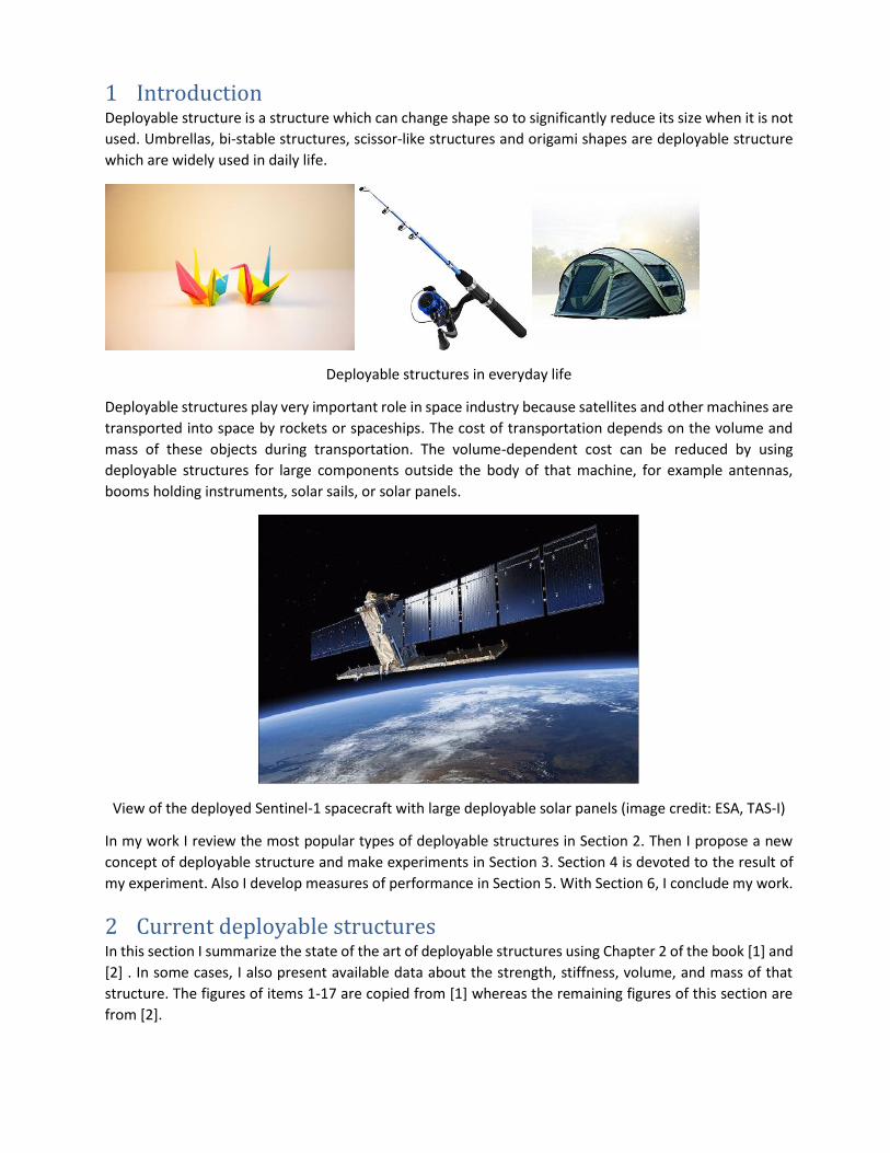
1 Introduction Deployable structure is a structure which can change shape so to significantly reduce its size when it is not
used. Umbrellas, bi-stable structures, scissor-like structures and origami shapes are deployable structure
which are widely used in daily life.
Deployable structures in everyday life
Deployable structures play very important role in space industry because satellites and other machines are
transported into space by rockets or spaceships. The cost of transportation depends on the volume and
mass of these objects during transportation. The volume-dependent cost can be reduced by using
deployable structures for large components outside the body of that machine, for example antennas,
booms holding instruments, solar sails, or solar panels.
View of the deployed Sentinel-1 spacecraft with large deployable solar panels (image credit: ESA, TAS-I)
In my work I review the most popular types of deployable structures in Section 2. Then I propose a new
concept of deployable structure and make experiments in Section 3. Section 4 is devoted to the result of
my experiment. Also I develop measures of performance in Section 5. With Section 6, I conclude my work.
2 Current deployable structures In this section I summarize the state of the art of deployable structures using Chapter 2 of the book [1] and
[2] . In some cases, I also present available data about the strength, stiffness, volume, and mass of that
structure. The figures of items 1-17 are copied from [1] whereas the remaining figures of this section are
from [2].
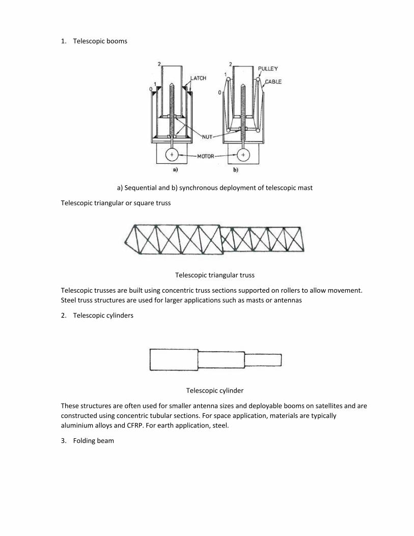
1. Telescopic booms
a) Sequential and b) synchronous deployment of telescopic mast
Telescopic triangular or square truss
Telescopic triangular truss
Telescopic trusses are built using concentric truss sections supported on rollers to allow movement.
Steel truss structures are used for larger applications such as masts or antennas
2. Telescopic cylinders
Telescopic cylinder
These structures are often used for smaller antenna sizes and deployable booms on satellites and are
constructed using concentric tubular sections. For space application, materials are typically
aluminium alloys and CFRP. For earth application, steel.
3. Folding beam
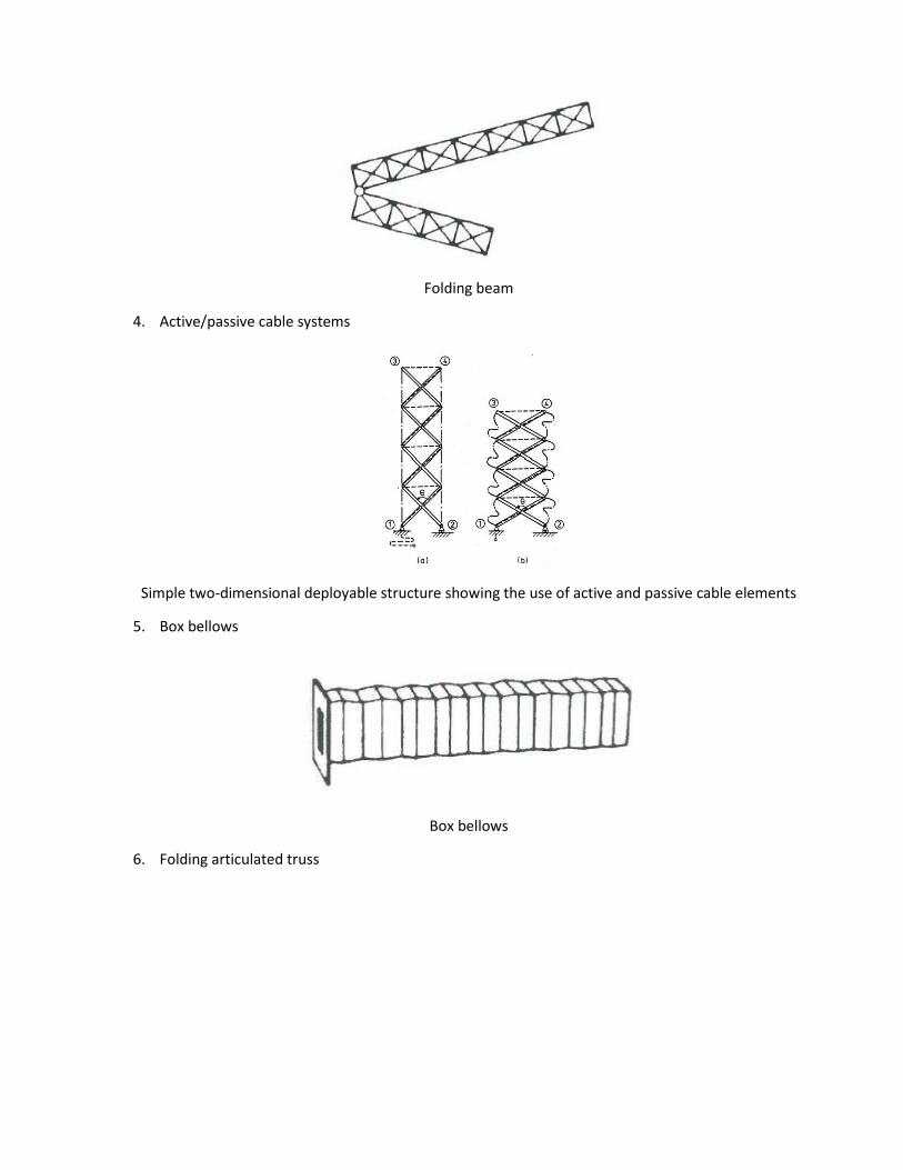
Folding beam
4. Active/passive cable systems
Simple two-dimensional deployable structure showing the use of active and passive cable elements
5. Box bellows
Box bellows
6. Folding articulated truss
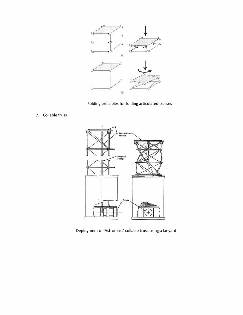
Folding principles for folding articulated trusses
7. Coilable truss
Deployment of ‘Astromast’ coilable truss using a lanyard
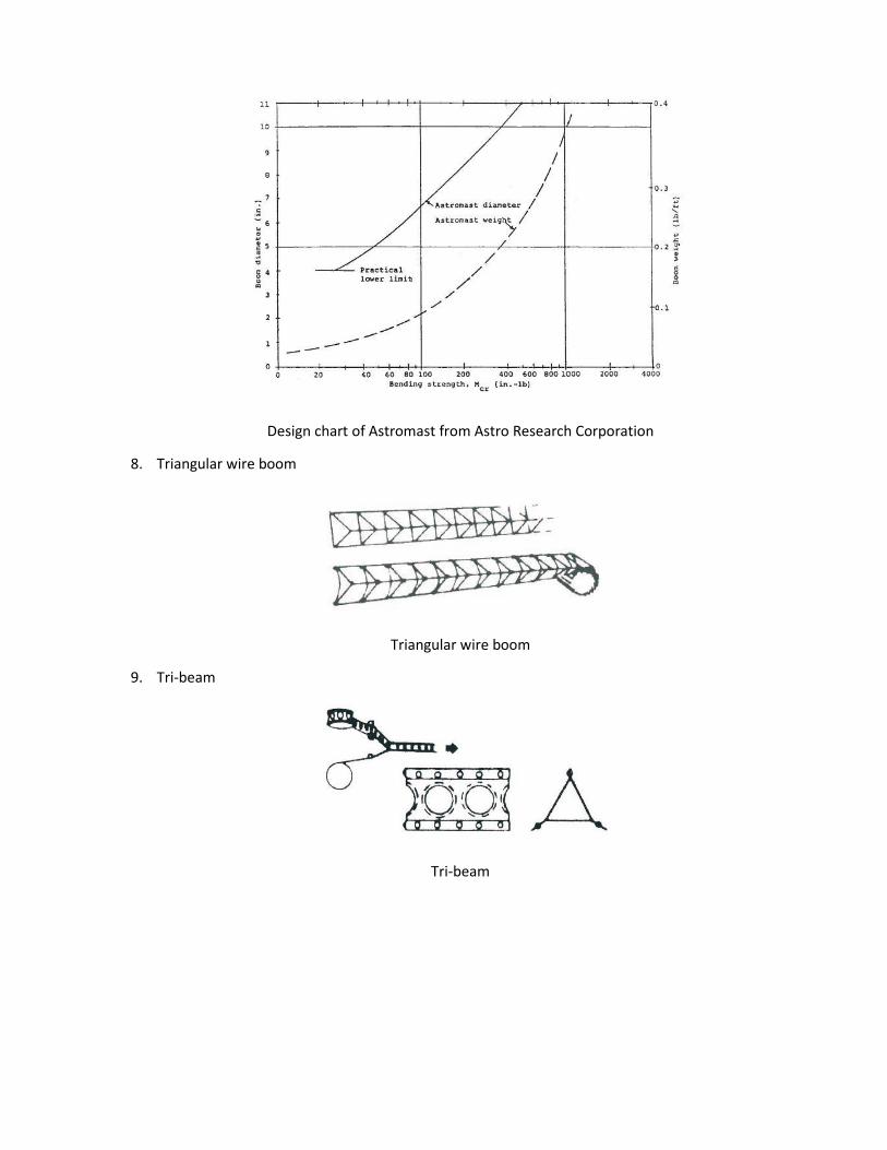
Design chart of Astromast from Astro Research Corporation
8. Triangular wire boom
Triangular wire boom
9. Tri-beam
Tri-beam
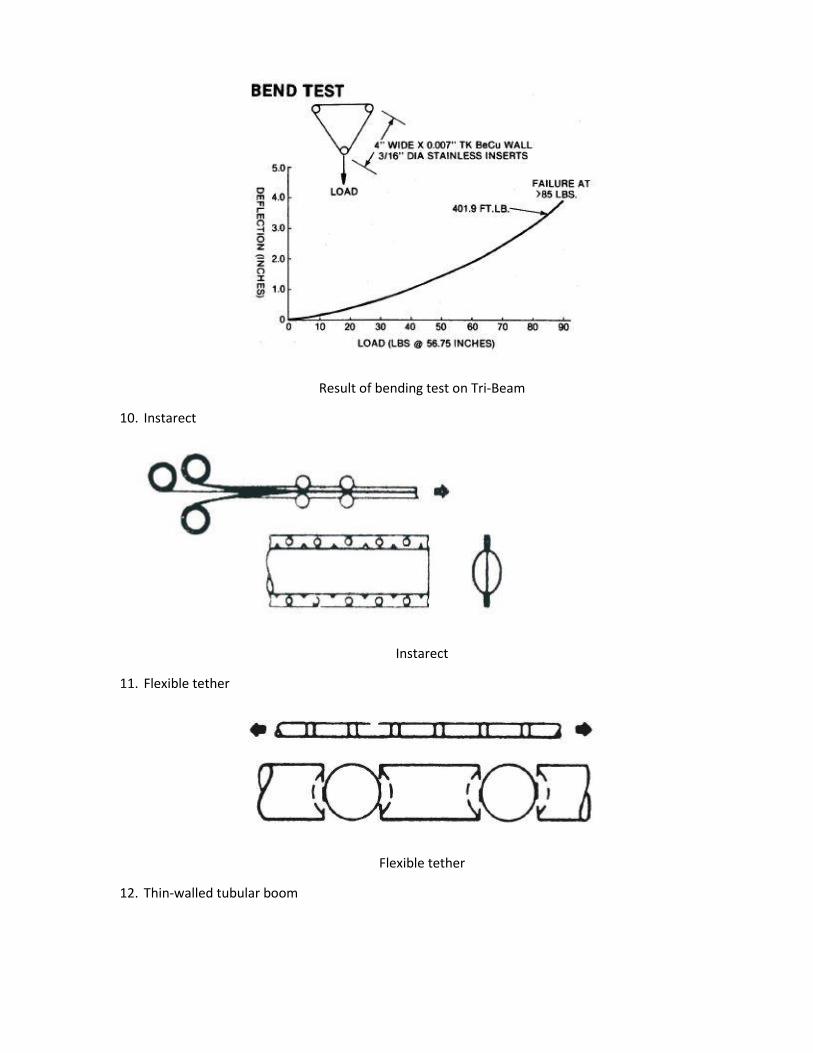
Result of bending test on Tri-Beam
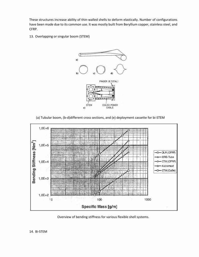
10. Instarect
Instarect
11. Flexible tether
Flexible tether
12. Thin-walled tubular boom
These structures increase ability of thin-walled shells to deform elastically. Number of configurations
have been made due to its common use. It was mostly built from Beryllium copper, stainless steel, and
CFRP.
13. Overlapping or singular boom (STEM)
(a) Tubular boom, (b-d)different cross sections, and (e) deployment cassette for bi-STEM
Overview of bending stiffness for various flexible shell systems.
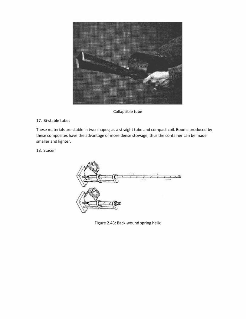
14. Bi-STEM
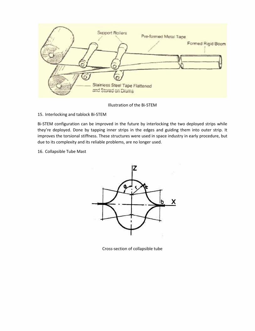
Illustration of the Bi-STEM
15. Interlocking and tablock Bi-STEM
Bi-STEM configuration can be improved in the future by interlocking the two deployed strips while
they’re deployed. Done by tapping inner strips in the edges and guiding them into outer strip. It
improves the torsional stiffness. These structures were used in space industry in early procedure, but
due to its complexity and its reliable problems, are no longer used.
16. Collapsible Tube Mast
Cross-section of collapsible tube
Collapsible tube
17. Bi-stable tubes
These materials are stable in two shapes; as a straight tube and compact coil. Booms produced by
these composites have the advantage of more dense stowage, thus the container can be made
smaller and lighter.
18. Stacer
Figure 2.43: Back-wound spring helix
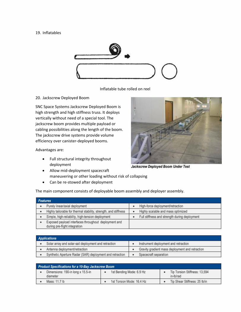
19. Inflatables
Inflatable tube rolled on reel
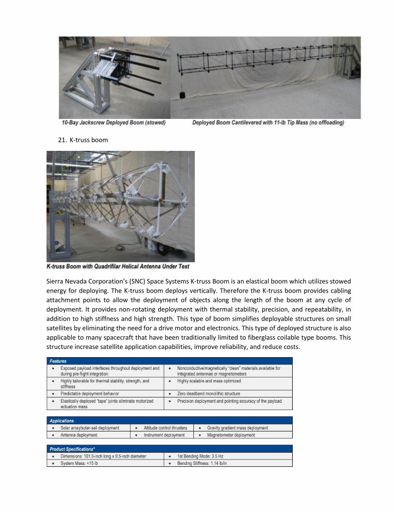
20. Jackscrew Deployed Boom
SNC Space Systems Jackscrew Deployed Boom is
high strength and high stiffness truss. It deploys
vertically without need of a special tool. The
jackscrew boom provides multiple payload or
cabling possibilities along the length of the boom.
The jackscrew drive systems provide volume
efficiency over canister-deployed booms.
Advantages are:
Full structural integrity throughout
deployment
Allow mid-deployment spacecraft
maneuvering or other loading without risk of collapsing
Can be re-stowed after deployment
The main component consists of deployable boom assembly and deployer assembly.
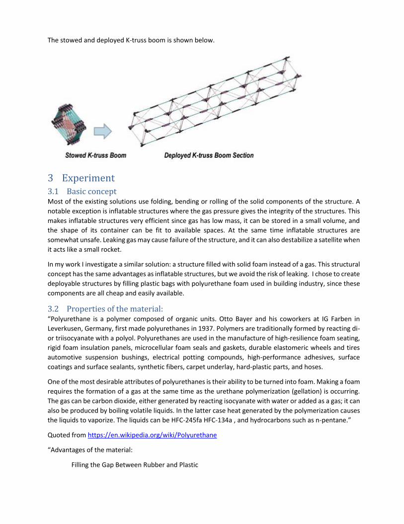
21. K-truss boom
Sierra Nevada Corporation’s (SNC) Space Systems K-truss Boom is an elastical boom which utilizes stowed
energy for deploying. The K-truss boom deploys vertically. Therefore the K-truss boom provides cabling
attachment points to allow the deployment of objects along the length of the boom at any cycle of
deployment. It provides non-rotating deployment with thermal stability, precision, and repeatability, in
addition to high stiffness and high strength. This type of boom simplifies deployable structures on small
satellites by eliminating the need for a drive motor and electronics. This type of deployed structure is also
applicable to many spacecraft that have been traditionally limited to fiberglass coilable type booms. This
structure increase satellite application capabilities, improve reliability, and reduce costs.
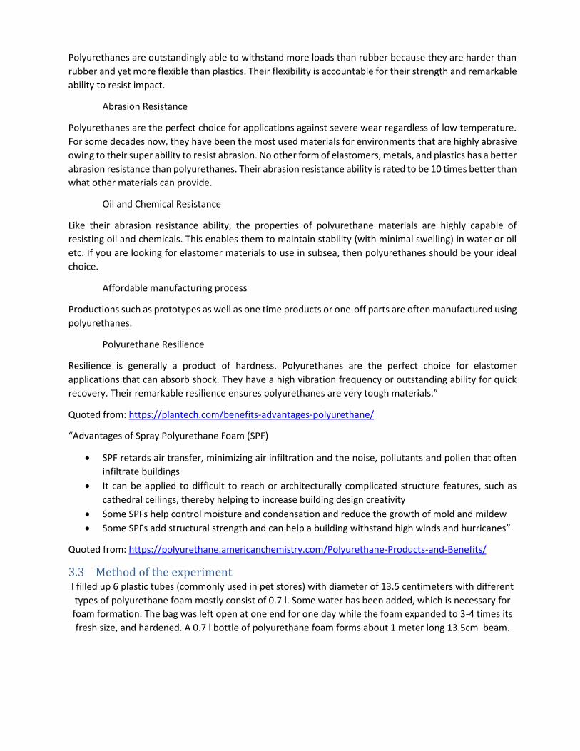
The stowed and deployed K-truss boom is shown below.
3 Experiment 3.1 Basic concept Most of the existing solutions use folding, bending or rolling of the solid components of the structure. A
notable exception is inflatable structures where the gas pressure gives the integrity of the structures. This
makes inflatable structures very efficient since gas has low mass, it can be stored in a small volume, and
the shape of its container can be fit to available spaces. At the same time inflatable structures are
somewhat unsafe. Leaking gas may cause failure of the structure, and it can also destabilize a satellite when
it acts like a small rocket.
In my work I investigate a similar solution: a structure filled with solid foam instead of a gas. This structural
concept has the same advantages as inflatable structures, but we avoid the risk of leaking. I chose to create
deployable structures by filling plastic bags with polyurethane foam used in building industry, since these
components are all cheap and easily available.
3.2 Properties of the material: “Polyurethane is a polymer composed of organic units. Otto Bayer and his coworkers at IG Farben in
Leverkusen, Germany, first made polyurethanes in 1937. Polymers are traditionally formed by reacting di-
or triisocyanate with a polyol. Polyurethanes are used in the manufacture of high-resilience foam seating,
rigid foam insulation panels, microcellular foam seals and gaskets, durable elastomeric wheels and tires
automotive suspension bushings, electrical potting compounds, high-performance adhesives, surface
coatings and surface sealants, synthetic fibers, carpet underlay, hard-plastic parts, and hoses.
One of the most desirable attributes of polyurethanes is their ability to be turned into foam. Making a foam
requires the formation of a gas at the same time as the urethane polymerization (gellation) is occurring.
The gas can be carbon dioxide, either generated by reacting isocyanate with water or added as a gas; it can
also be produced by boiling volatile liquids. In the latter case heat generated by the polymerization causes
the liquids to vaporize. The liquids can be HFC-245fa HFC-134a , and hydrocarbons such as n-pentane.”
Quoted from https://en.wikipedia.org/wiki/Polyurethane
“Advantages of the material:
Filling the Gap Between Rubber and Plastic
Polyurethanes are outstandingly able to withstand more loads than rubber because they are harder than
rubber and yet more flexible than plastics. Their flexibility is accountable for their strength and remarkable
ability to resist impact.
Abrasion Resistance
Polyurethanes are the perfect choice for applications against severe wear regardless of low temperature.
For some decades now, they have been the most used materials for environments that are highly abrasive
owing to their super ability to resist abrasion. No other form of elastomers, metals, and plastics has a better
abrasion resistance than polyurethanes. Their abrasion resistance ability is rated to be 10 times better than
what other materials can provide.
Oil and Chemical Resistance
Like their abrasion resistance ability, the properties of polyurethane materials are highly capable of
resisting oil and chemicals. This enables them to maintain stability (with minimal swelling) in water or oil
etc. If you are looking for elastomer materials to use in subsea, then polyurethanes should be your ideal
choice.
Affordable manufacturing process
Productions such as prototypes as well as one time products or one-off parts are often manufactured using
polyurethanes.
Polyurethane Resilience
Resilience is generally a product of hardness. Polyurethanes are the perfect choice for elastomer
applications that can absorb shock. They have a high vibration frequency or outstanding ability for quick
recovery. Their remarkable resilience ensures polyurethanes are very tough materials.”
Quoted from: https://plantech.com/benefits-advantages-polyurethane/
“Advantages of Spray Polyurethane Foam (SPF)
SPF retards air transfer, minimizing air infiltration and the noise, pollutants and pollen that often
infiltrate buildings
It can be applied to difficult to reach or architecturally complicated structure features, such as
cathedral ceilings, thereby helping to increase building design creativity
Some SPFs help control moisture and condensation and reduce the growth of mold and mildew
Some SPFs add structural strength and can help a building withstand high winds and hurricanes”
Quoted from: https://polyurethane.americanchemistry.com/Polyurethane-Products-and-Benefits/
3.3 Method of the experiment I filled up 6 plastic tubes (commonly used in pet stores) with diameter of 13.5 centimeters with different
types of polyurethane foam mostly consist of 0.7 l. Some water has been added, which is necessary for
foam formation. The bag was left open at one end for one day while the foam expanded to 3-4 times its
fresh size, and hardened. A 0.7 l bottle of polyurethane foam forms about 1 meter long 13.5cm beam.
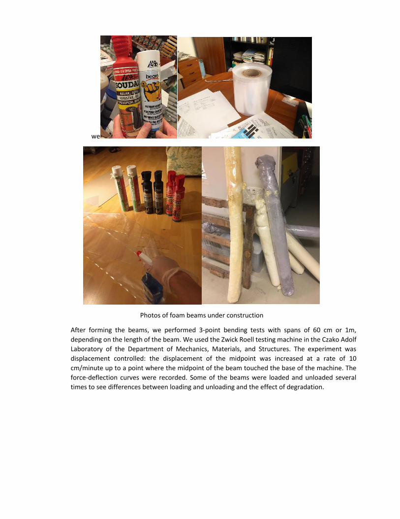
we
Photos of foam beams under construction
After forming the beams, we performed 3-point bending tests with spans of 60 cm or 1m,
depending on the length of the beam. We used the Zwick Roell testing machine in the Czako Adolf
Laboratory of the Department of Mechanics, Materials, and Structures. The experiment was
displacement controlled: the displacement of the midpoint was increased at a rate of 10
cm/minute up to a point where the midpoint of the beam touched the base of the machine. The
force-deflection curves were recorded. Some of the beams were loaded and unloaded several
times to see differences between loading and unloading and the effect of degradation.
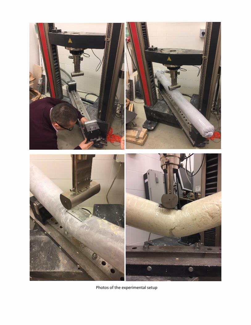
Photos of the experimental setup
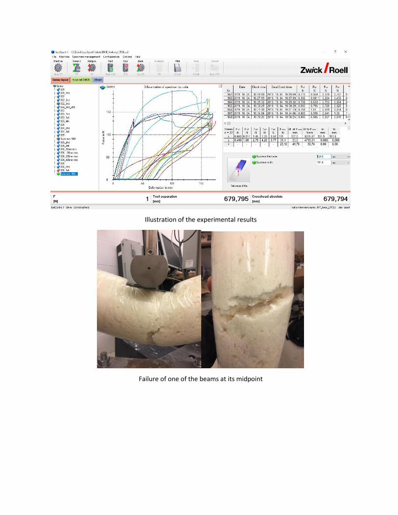
Illustration of the experimental results
Failure of one of the beams at its midpoint
0
10
20
30
40
50
60
70
800 5
11
16
21
27
32
38
43
48
54
59
64
70
75
80
86
91
96
10
2
10
7
11
3
11
8
12
3
12
9
13
4
Beam 1
First compression Second compression
-50
0
50
100
150
200
0 71
32
02
63
33
94
65
25
96
57
27
88
59
19
81
05
11
11
18
12
41
31
13
71
44
15
01
57
16
3
Beam 2
First compression
Second compression
Third compression with 200Nmm/minute
-50
0
50
100
150
200
0 6
12
18
24
31
37
43
49
55
61
68
74
80
86
92
98
10
4
11
1
11
7
12
3
12
9
13
5
14
1
14
7
15
3
16
0
Beam 3
First compression Second compression Third compression
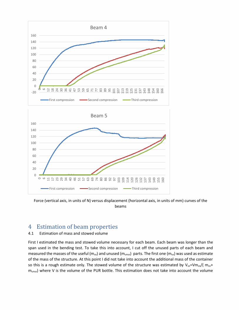
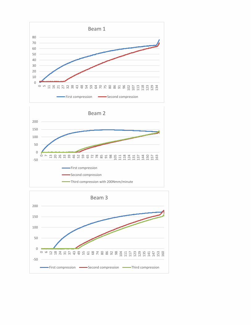
Force (vertical axis, in units of N) versus displacement (horizontal axis, in units of mm) curves of the
beams
4 Estimation of beam properties 4.1 Estimation of mass and stowed volume
First I estimated the mass and stowed volume necessary for each beam. Each beam was longer than the
span used in the bending test. To take this into account, I cut off the unused parts of each beam and
measured the masses of the useful (mus) and unused (munus) parts. The first one (mus) was used as estimate
of the mass of the structure. At this point I did not take into account the additional mass of the container
so this is a rough estimate only. The stowed volume of the structure was estimated by Vus=Vmus/( mus+
munus) where V is the volume of the PUR bottle. This estimation does not take into account the volume
-20
0
20
40
60
80
100
120
140
1600 6
12
18
24
30
36
41
47
53
59
65
71
77
83
89
95
10
11
07
11
31
19
12
51
31
13
71
43
14
81
54
16
01
66
Beam 4
First compression Second compression Third compression
0
20
40
60
80
100
120
140
160
0 6
11
17
23
29
34
40
46
51
57
63
69
74
80
86
92
97
10
3
10
9
11
4
12
0
12
6
13
2
13
7
14
3
14
91
55
16
0
Beam 5
First compression Second compression Third compression
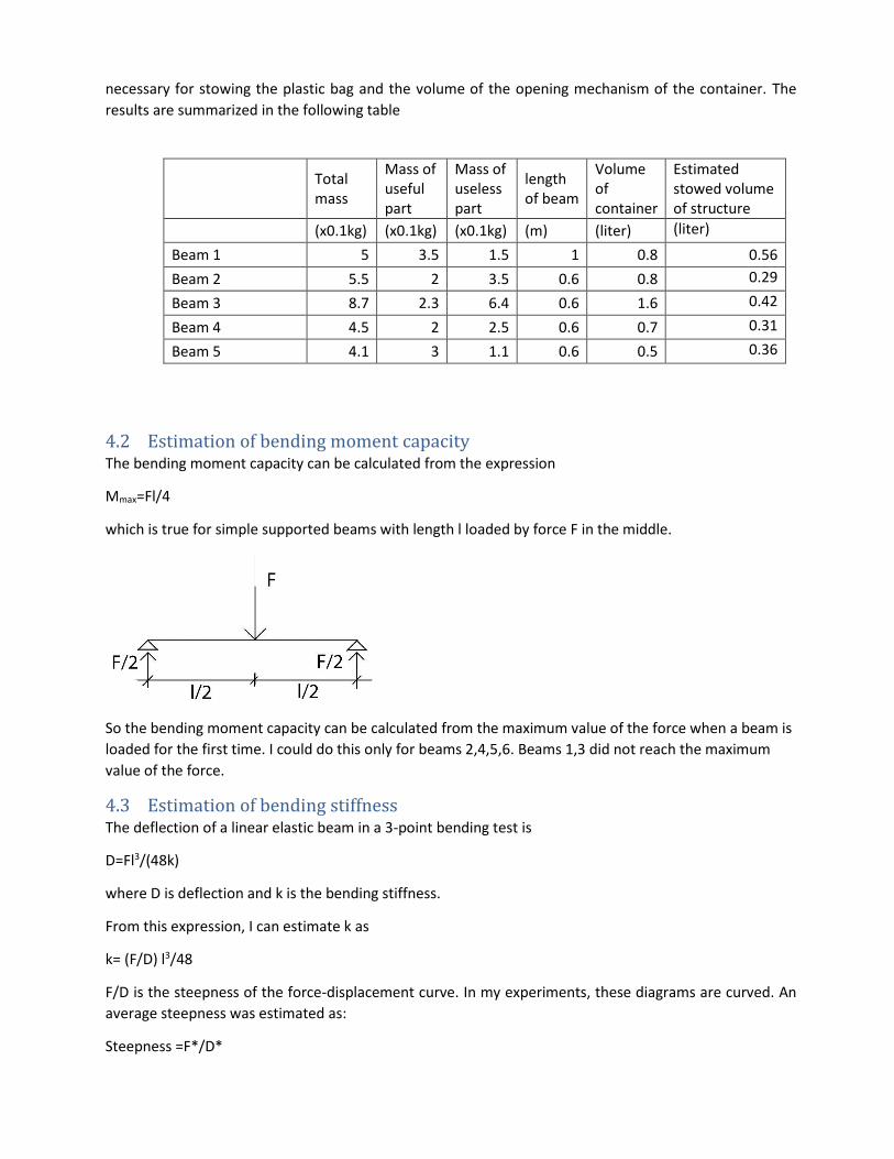
necessary for stowing the plastic bag and the volume of the opening mechanism of the container. The
results are summarized in the following table
4.2 Estimation of bending moment capacity The bending moment capacity can be calculated from the expression
Mmax=Fl/4
which is true for simple supported beams with length l loaded by force F in the middle.
So the bending moment capacity can be calculated from the maximum value of the force when a beam is
loaded for the first time. I could do this only for beams 2,4,5,6. Beams 1,3 did not reach the maximum
value of the force.
4.3 Estimation of bending stiffness The deflection of a linear elastic beam in a 3-point bending test is
D=Fl3/(48k)
where D is deflection and k is the bending stiffness.
From this expression, I can estimate k as
k= (F/D) l3/48
F/D is the steepness of the force-displacement curve. In my experiments, these diagrams are curved. An
average steepness was estimated as:
Steepness =F*/D*
Total mass
Mass of useful part
Mass of useless part
length of beam
Volume of container
Estimated stowed volume of structure
(x0.1kg) (x0.1kg) (x0.1kg) (m) (liter) (liter)
Beam 1 5 3.5 1.5 1 0.8 0.56 Beam 2 5.5 2 3.5 0.6 0.8 0.29
Beam 3 8.7 2.3 6.4 0.6 1.6 0.42
Beam 4 4.5 2 2.5 0.6 0.7 0.31
Beam 5 4.1 3 1.1 0.6 0.5 0.36
where F* is 1/3 of the maximum value of the force, D* is the deflection measured under F* minus the initial
deflection. The curves of the first-time loading were used for this. For beams 1 and 3, I used the largest
value reached during the experiment as maximum value.
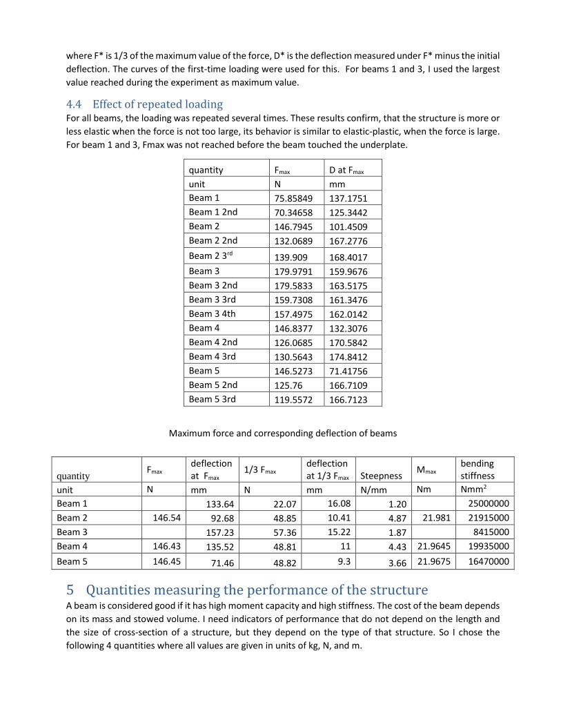
4.4 Effect of repeated loading For all beams, the loading was repeated several times. These results confirm, that the structure is more or
less elastic when the force is not too large, its behavior is similar to elastic-plastic, when the force is large.
For beam 1 and 3, Fmax was not reached before the beam touched the underplate.
quantity Fmax D at Fmax
unit N mm
Beam 1 75.85849 137.1751
Beam 1 2nd 70.34658 125.3442
Beam 2 146.7945 101.4509
Beam 2 2nd 132.0689 167.2776
Beam 2 3rd 139.909 168.4017
Beam 3 179.9791 159.9676
Beam 3 2nd 179.5833 163.5175
Beam 3 3rd 159.7308 161.3476
Beam 3 4th 157.4975 162.0142
Beam 4 146.8377 132.3076
Beam 4 2nd 126.0685 170.5842
Beam 4 3rd 130.5643 174.8412
Beam 5 146.5273 71.41756
Beam 5 2nd 125.76 166.7109
Beam 5 3rd 119.5572 166.7123
Maximum force and corresponding deflection of beams
5 Quantities measuring the performance of the structure A beam is considered good if it has high moment capacity and high stiffness. The cost of the beam depends
on its mass and stowed volume. I need indicators of performance that do not depend on the length and
the size of cross-section of a structure, but they depend on the type of that structure. So I chose the
following 4 quantities where all values are given in units of kg, N, and m.
quantity Fmax
deflection at Fmax
1/3 Fmax deflection at 1/3 Fmax Steepness
Mmax bending stiffness
unit N mm N mm N/mm Nm Nmm2
Beam 1 133.64 22.07 16.08 1.20 25000000
Beam 2 146.54 92.68 48.85 10.41 4.87 21.981 21915000
Beam 3 157.23 57.36 15.22 1.87 8415000
Beam 4 146.43 135.52 48.81 11 4.43 21.9645 19935000
Beam 5 146.45 71.46 48.82 9.3 3.66 21.9675 16470000
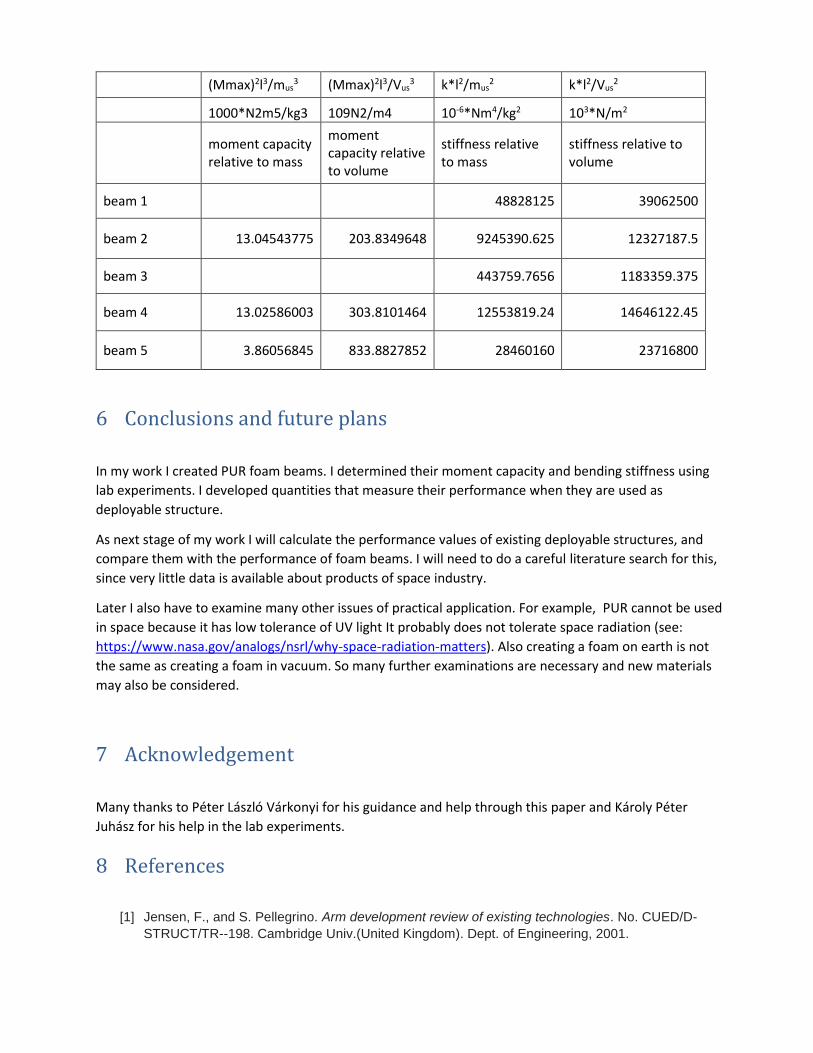
(Mmax)2l3/mus3 (Mmax)2l3/Vus
3 k*l2/mus2 k*l2/Vus
2
1000*N2m5/kg3 109N2/m4 10-6*Nm4/kg2 103*N/m2
moment capacity relative to mass
moment capacity relative to volume
stiffness relative to mass
stiffness relative to volume
beam 1 48828125 39062500
beam 2 13.04543775 203.8349648 9245390.625 12327187.5
beam 3 443759.7656 1183359.375
beam 4 13.02586003 303.8101464 12553819.24 14646122.45
beam 5 3.86056845 833.8827852 28460160 23716800
6 Conclusions and future plans
In my work I created PUR foam beams. I determined their moment capacity and bending stiffness using
lab experiments. I developed quantities that measure their performance when they are used as
deployable structure.
As next stage of my work I will calculate the performance values of existing deployable structures, and
compare them with the performance of foam beams. I will need to do a careful literature search for this,
since very little data is available about products of space industry.
Later I also have to examine many other issues of practical application. For example, PUR cannot be used
in space because it has low tolerance of UV light It probably does not tolerate space radiation (see:
https://www.nasa.gov/analogs/nsrl/why-space-radiation-matters). Also creating a foam on earth is not
the same as creating a foam in vacuum. So many further examinations are necessary and new materials
may also be considered.
7 Acknowledgement
Many thanks to Péter László Várkonyi for his guidance and help through this paper and Károly Péter
Juhász for his help in the lab experiments.
8 References
[1] Jensen, F., and S. Pellegrino. Arm development review of existing technologies. No. CUED/D-
STRUCT/TR--198. Cambridge Univ.(United Kingdom). Dept. of Engineering, 2001.

[2] Space technologies product catalog 201 by Sierra Nevada corporation’ space systems.
Downloaded from https://www.sncorp.com/media/2756/snc-space-technologies-product-
catalog_2019.pdf