Embed Size (px)
Citation preview
27 | Fascicule 4
ANNALS of Faculty Engineering Hunedoara – International Journal of Engineering Tome XIV [2016] – Fascicule 4 [November] ISSN: 1584-2665 [print; online] ISSN: 1584-2673 [CD-Rom; online] a free-access multidisciplinary publication of the Faculty of Engineering Hunedoara
1. Antoni JOHN, 2. Malgorzata JOHN
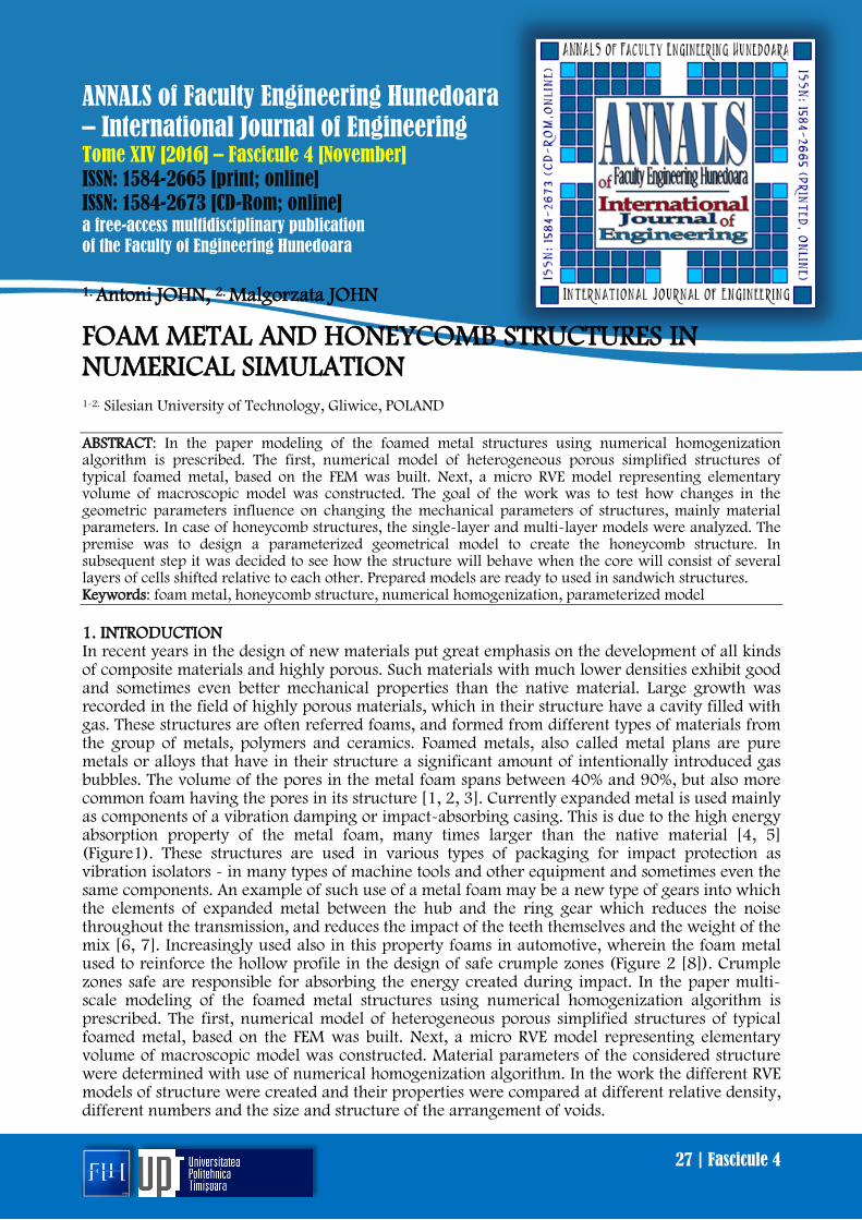
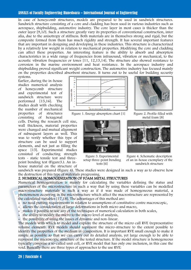
FOAM METAL AND HONEYCOMB STRUCTURES IN NUMERICAL SIMULATION 1-2. Silesian University of Technology, Gliwice, POLAND ABSTRACT: In the paper modeling of the foamed metal structures using numerical homogenization algorithm is prescribed. The first, numerical model of heterogeneous porous simplified structures of typical foamed metal, based on the FEM was built. Next, a micro RVE model representing elementary volume of macroscopic model was constructed. The goal of the work was to test how changes in the geometric parameters influence on changing the mechanical parameters of structures, mainly material parameters. In case of honeycomb structures, the single-layer and multi-layer models were analyzed. The premise was to design a parameterized geometrical model to create the honeycomb structure. In subsequent step it was decided to see how the structure will behave when the core will consist of several layers of cells shifted relative to each other. Prepared models are ready to used in sandwich structures. Keywords: foam metal, honeycomb structure, numerical homogenization, parameterized model 1. INTRODUCTION In recent years in the design of new materials put great emphasis on the development of all kinds of composite materials and highly porous. Such materials with much lower densities exhibit good and sometimes even better mechanical properties than the native material. Large growth was recorded in the field of highly porous materials, which in their structure have a cavity filled with gas. These structures are often referred foams, and formed from different types of materials from the group of metals, polymers and ceramics. Foamed metals, also called metal plans are pure metals or alloys that have in their structure a significant amount of intentionally introduced gas bubbles. The volume of the pores in the metal foam spans between 40% and 90%, but also more common foam having the pores in its structure [1, 2, 3]. Currently expanded metal is used mainly as components of a vibration damping or impact-absorbing casing. This is due to the high energy absorption property of the metal foam, many times larger than the native material [4, 5] (Figure1). These structures are used in various types of packaging for impact protection as vibration isolators - in many types of machine tools and other equipment and sometimes even the same components. An example of such use of a metal foam may be a new type of gears into which the elements of expanded metal between the hub and the ring gear which reduces the noise throughout the transmission, and reduces the impact of the teeth themselves and the weight of the mix [6, 7]. Increasingly used also in this property foams in automotive, wherein the foam metal used to reinforce the hollow profile in the design of safe crumple zones (Figure 2 [8]). Crumple zones safe are responsible for absorbing the energy created during impact. In the paper multi-scale modeling of the foamed metal structures using numerical homogenization algorithm is prescribed. The first, numerical model of heterogeneous porous simplified structures of typical foamed metal, based on the FEM was built. Next, a micro RVE model representing elementary volume of macroscopic model was constructed. Material parameters of the considered structure were determined with use of numerical homogenization algorithm. In the work the different RVE models of structure were created and their properties were compared at different relative density, different numbers and the size and structure of the arrangement of voids.
ANNALS of Faculty Engineering Hunedoara – International Journal of Engineering
28 | Fascicule 4
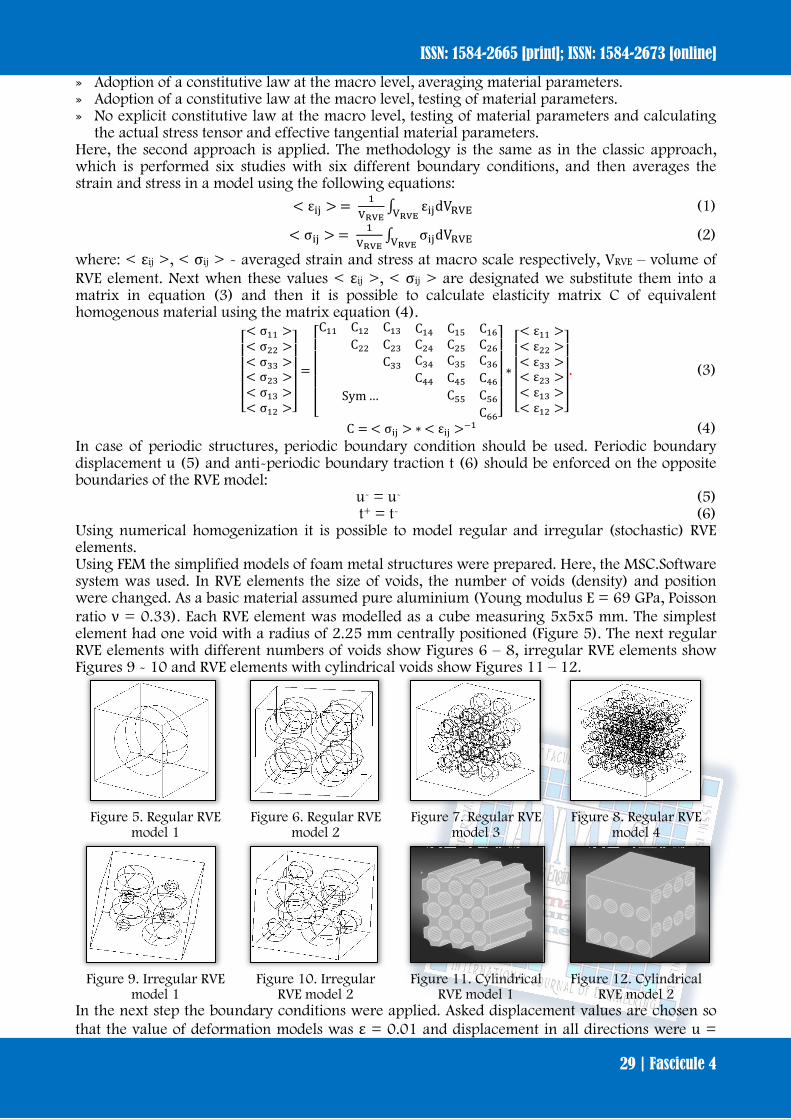
In case of honeycomb structures, models are prepared to be used in sandwich structures. Sandwich structure consisting of a core and cladding has been used in various industries such as aerospace, shipbuilding, automotive industry. The core layer in most cases is thicker than the outer layer [9,10]. Such a structure greatly vary its properties of conventional construction, inter alia, due to the anisotropy of stiffness. Both materials are in themselves strong and rigid, but the composite formed from them has much rigidity and strength. It has several important features that are important in designing and developing in these industries. This structure is characterized by a relatively low weight in relation to mechanical properties. Modifying the core and cladding can affect these properties. An interesting feature is the ability to absorb and absorption characteristics in a wide range of frequencies from infrasound, vibration or mechanical, to the acoustic vibration frequencies or tones [11, 12,13,14]. The structure also showed resistance to corrosion in the marine environment and heat resistance. In the aerospace industry and shipbuilding proved significant weight construction. The automotive industry has focused mainly on the properties described absorbent structure. It turns out to be useful for building security systems. Earlier, during the in-house studies numerical analysis of honeycomb structure and experimental test of sandwich structure were performed [15,16]. The studies dealt with checking the number of mechanical properties of structures consisting of hexagonal cells. During the research cell size, wall thickness, material properties were changed and mutual alignment of subsequent layers as well. This was to verify whether this type of structure can be used to support elements, and not just as filling the space [15]. Experimental studies consisted of conducting strength tests - static tensile test and three-point bending test (Figure3.). An in-house material on the structure of sandwich was prepared (Figure 4). These studies were designed in such a way as to observe how the destruction of this type of materials progressing. 2. NUMERICAL HOMOGENIZATION OF FOAM METAL STRUCTURES Numerical homogenization is mainly for calculating the variables defining the status and parameters of the microstructure in such a way that by using these variables can be modelled macrostructure materials in such a way as if it was made of homogeneous material, a phenomenon occurring in the microstructure which affect the macrostructure are represented by the calculated variables [17,18]. The advantages of this method are: » no need putting requirements in relation to assumptions of constitutive centre macroscopic, » allows the consideration of large deformations in both micro and macro, » makes it possible to use any of the techniques of numerical calculation in both scales, » the ability to modify the micro to the macro level of analysis, » the possibility of using the issues of dynamic and non-linear. The models with which to model and explore the structure of the micro call RVE (representative volume element). RVE models should represent the micro-structure to the extent possible to identify the properties of the medium in composition. It is important RVE small enough to make it simple as possible so that we can carry out its detailed analysis, yet large enough to be able to represent the microscopic structure of the tested structure. If the model structure is homogeneous typically comprise a so-called unit cell, or RVE model that has only one inclusion, in this case the void. Basically there are three types of approaches to the use RVE:
Figure 1. Energy absorption chart [1] Figure 2. Profile filled with
metal foam [8]
Figure 3. Experimental
setup three-point bending tests [6]
Figure 4. Schematic description of an in-house exemplary of the
sandwich structure
ISSN: 1584-2665 [print]; ISSN: 1584-2673 [online]
29 | Fascicule 4
» Adoption of a constitutive law at the macro level, averaging material parameters. » Adoption of a constitutive law at the macro level, testing of material parameters. » No explicit constitutive law at the macro level, testing of material parameters and calculating
the actual stress tensor and effective tangential material parameters. Here, the second approach is applied. The methodology is the same as in the classic approach, which is performed six studies with six different boundary conditions, and then averages the strain and stress in a model using the following equations:
< εij > = 1VRVE
∫ εijdVRVEVRVE (1)
< σij > = 1VRVE
∫ σijdVRVEVRVE (2)
where: < εij >, < σij > - averaged strain and stress at macro scale respectively, VRVE – volume of RVE element. Next when these values < εij >, < σij > are designated we substitute them into a matrix in equation (3) and then it is possible to calculate elasticity matrix C of equivalent homogenous material using the matrix equation (4).
⎣⎢⎢⎢⎢⎡< σ11 >< σ22 >< σ33 >< σ23 >< σ13 >< σ12 >⎦
⎥⎥⎥⎥⎤
=
⎣⎢⎢⎢⎢⎢⎡C11 C12 C13
C22 C23C33
C14 C15 C16C24 C25 C26C34 C35 C36
Sym …C44 C45 C46
C55 C56C66⎦
⎥⎥⎥⎥⎥⎤
∗
⎣⎢⎢⎢⎢⎡< ε11 >< ε22 >< ε33 >< ε23 >< ε13 >< ε12 >⎦
⎥⎥⎥⎥⎤
. (3)
C = < σij > ∗ < εij >−1 (4) In case of periodic structures, periodic boundary condition should be used. Periodic boundary displacement u (5) and anti-periodic boundary traction t (6) should be enforced on the opposite boundaries of the RVE model:
u- = u- (5) t+ = t- (6)
Using numerical homogenization it is possible to model regular and irregular (stochastic) RVE elements. Using FEM the simplified models of foam metal structures were prepared. Here, the MSC.Software system was used. In RVE elements the size of voids, the number of voids (density) and position were changed. As a basic material assumed pure aluminium (Young modulus E = 69 GPa, Poisson ratio ν = 0.33). Each RVE element was modelled as a cube measuring 5x5x5 mm. The simplest element had one void with a radius of 2.25 mm centrally positioned (Figure 5). The next regular RVE elements with different numbers of voids show Figures 6 – 8, irregular RVE elements show Figures 9 - 10 and RVE elements with cylindrical voids show Figures 11 – 12.
Figure 5. Regular RVE
model 1 Figure 6. Regular RVE
model 2 Figure 7. Regular RVE
model 3 Figure 8. Regular RVE
model 4
Figure 9. Irregular RVE
model 1 Figure 10. Irregular
RVE model 2 Figure 11. Cylindrical
RVE model 1 Figure 12. Cylindrical
RVE model 2 In the next step the boundary conditions were applied. Asked displacement values are chosen so that the value of deformation models was ε = 0.01 and displacement in all directions were u =
ANNALS of Faculty Engineering Hunedoara – International Journal of Engineering
30 | Fascicule 4
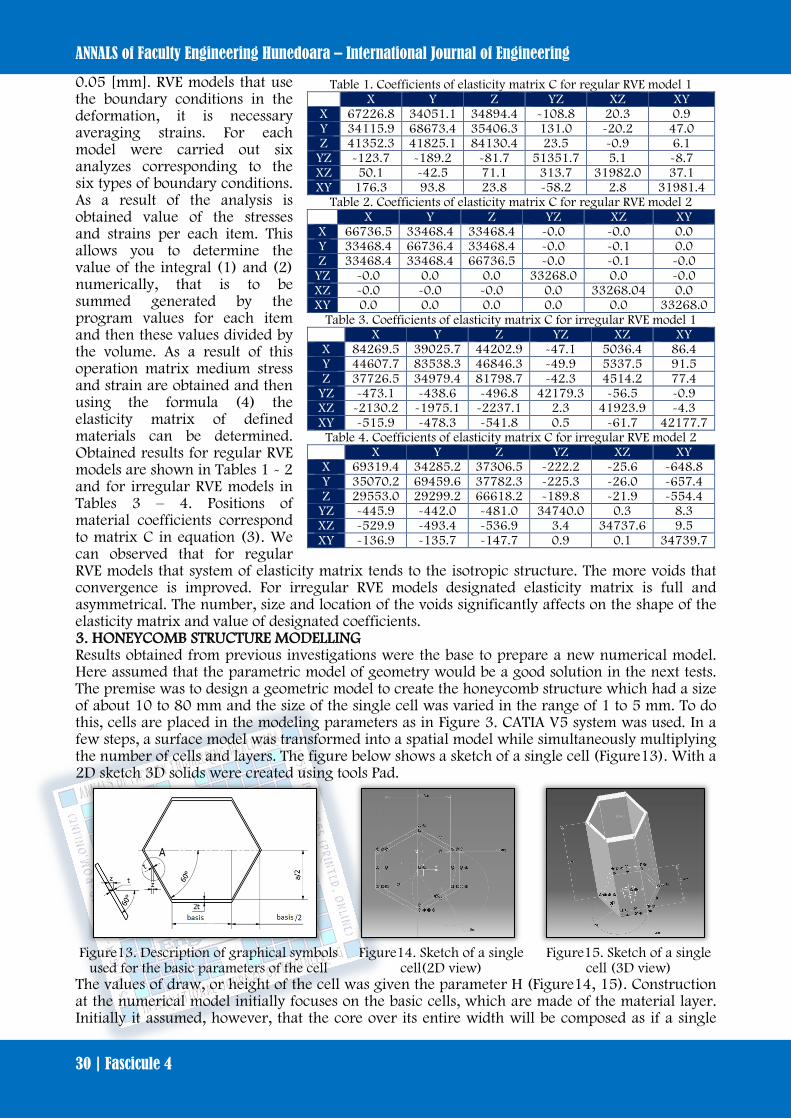
0.05 [mm]. RVE models that use the boundary conditions in the deformation, it is necessary averaging strains. For each model were carried out six analyzes corresponding to the six types of boundary conditions. As a result of the analysis is obtained value of the stresses and strains per each item. This allows you to determine the value of the integral (1) and (2) numerically, that is to be summed generated by the program values for each item and then these values divided by the volume. As a result of this operation matrix medium stress and strain are obtained and then using the formula (4) the elasticity matrix of defined materials can be determined. Obtained results for regular RVE models are shown in Tables 1 - 2 and for irregular RVE models in Tables 3 – 4. Positions of material coefficients correspond to matrix C in equation (3). We can observed that for regular RVE models that system of elasticity matrix tends to the isotropic structure. The more voids that convergence is improved. For irregular RVE models designated elasticity matrix is full and asymmetrical. The number, size and location of the voids significantly affects on the shape of the elasticity matrix and value of designated coefficients. 3. HONEYCOMB STRUCTURE MODELLING Results obtained from previous investigations were the base to prepare a new numerical model. Here assumed that the parametric model of geometry would be a good solution in the next tests. The premise was to design a geometric model to create the honeycomb structure which had a size of about 10 to 80 mm and the size of the single cell was varied in the range of 1 to 5 mm. To do this, cells are placed in the modeling parameters as in Figure 3. CATIA V5 system was used. In a few steps, a surface model was transformed into a spatial model while simultaneously multiplying the number of cells and layers. The figure below shows a sketch of a single cell (Figure13). With a 2D sketch 3D solids were created using tools Pad.
Figure13. Description of graphical symbols
used for the basic parameters of the cell Figure14. Sketch of a single
cell(2D view) Figure15. Sketch of a single
cell (3D view) The values of draw, or height of the cell was given the parameter H (Figure14, 15). Construction at the numerical model initially focuses on the basic cells, which are made of the material layer. Initially it assumed, however, that the core over its entire width will be composed as if a single
Table 1. Coefficients of elasticity matrix C for regular RVE model 1 X Y Z YZ XZ XY
X 67226.8 34051.1 34894.4 -108.8 20.3 0.9 Y 34115.9 68673.4 35406.3 131.0 -20.2 47.0 Z 41352.3 41825.1 84130.4 23.5 -0.9 6.1
YZ -123.7 -189.2 -81.7 51351.7 5.1 -8.7 XZ 50.1 -42.5 71.1 313.7 31982.0 37.1 XY 176.3 93.8 23.8 -58.2 2.8 31981.4
Table 2. Coefficients of elasticity matrix C for regular RVE model 2 X Y Z YZ XZ XY
X 66736.5 33468.4 33468.4 -0.0 -0.0 0.0 Y 33468.4 66736.4 33468.4 -0.0 -0.1 0.0 Z 33468.4 33468.4 66736.5 -0.0 -0.1 -0.0
YZ -0.0 0.0 0.0 33268.0 0.0 -0.0 XZ -0.0 -0.0 -0.0 0.0 33268.04 0.0 XY 0.0 0.0 0.0 0.0 0.0 33268.0
Table 3. Coefficients of elasticity matrix C for irregular RVE model 1 X Y Z YZ XZ XY
X 84269.5 39025.7 44202.9 -47.1 5036.4 86.4 Y 44607.7 83538.3 46846.3 -49.9 5337.5 91.5 Z 37726.5 34979.4 81798.7 -42.3 4514.2 77.4
YZ -473.1 -438.6 -496.8 42179.3 -56.5 -0.9 XZ -2130.2 -1975.1 -2237.1 2.3 41923.9 -4.3 XY -515.9 -478.3 -541.8 0.5 -61.7 42177.7
Table 4. Coefficients of elasticity matrix C for irregular RVE model 2 X Y Z YZ XZ XY
X 69319.4 34285.2 37306.5 -222.2 -25.6 -648.8 Y 35070.2 69459.6 37782.3 -225.3 -26.0 -657.4 Z 29553.0 29299.2 66618.2 -189.8 -21.9 -554.4
YZ -445.9 -442.0 -481.0 34740.0 0.3 8.3 XZ -529.9 -493.4 -536.9 3.4 34737.6 9.5 XY -136.9 -135.7 -147.7 0.9 0.1 34739.7
ISSN: 1584-2665 [print]; ISSN: 1584-2673 [online]
31 | Fascicule 4
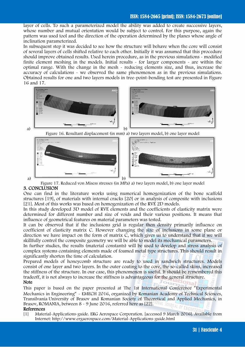
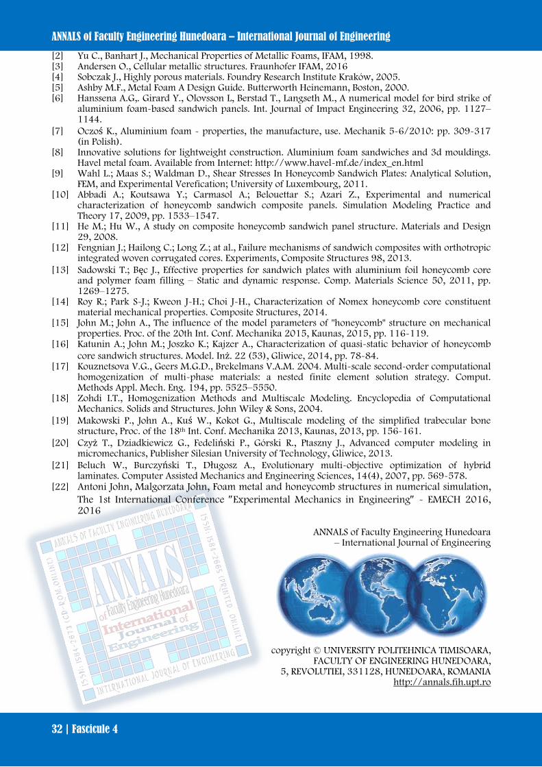
layer of cells. To such a parameterized model the ability was added to create successive layers, whose number and mutual orientation would be subject to control. For this purpose, again the pattern was used tool and the direction of the operation determined by the planes whose angle of inclination parameterized. In subsequent step it was decided to see how the structure will behave when the core will consist of several layers of cells shifted relative to each other. Initially it was assumed that this procedure should improve obtained results. Used herein procedure, as in the previous simulations - modified finite element meshing in the models. Initial results - for larger components - are within the optimal range. With the change in the mesh - reducing elements size, and thus, increase the accuracy of calculations - we observed the same phenomenon as in the previous simulations. Obtained results for one and two layers models in tree-point-bending test are presented in Figure 16 and 17.
a) b) Figure 16. Resultant displacement (in mm) a) two layers model, b) one layer model
a) b) Figure 17. Reduced von Misess stresses (in MPa) a) two layers model, b) one layer model
3. CONCLUSION One can find in the literature works using numerical homogenization of the bone scaffold structures [19], of materials with internal cracks [20] or in analysis of composite with inclusions [21]. Most of this works was based on homogenization of the RVE 2D models. In this study developed 3D model of RVE elements and the coefficients of elasticity matrix were determined for different number and size of voids and their various positions. It means that influence of geometrical features on material parameters was tested. It can be observed that if the inclusions grid is regular then density primarily influence on coefficient of elasticity matrix C. However changing the size of inclusions in some plane or direction we have impact on the form of matrix C, which gives us to understand that if we will skillfully control the composite geometry we will be able to model its mechanical parameters. In further studies, the results (material constants) will be used to develop and stress analysis of complex systems containing elements made of foamed metal type structures. This should result in significantly shorten the time of calculation. Prepared models of honeycomb structure are ready to used in sandwich structures. Models consist of one layer and two layers. In the outer coating to the core, the so-called skins, increased the stiffness of the structure. In our case, this phenomenon is useful. It should be remembered this tradeoff, it is not always to increase the stiffness is advantageous for the general structure. Note This paper is based on the paper presented at The 1st International Conference ″Experimental Mechanics in Engineering″ - EMECH 2016, organized by Romanian Academy of Technical Sciences, Transilvania University of Brasov and Romanian Society of Theoretical and Applied Mechanics, in Brasov, ROMANIA, between 8 - 9 June 2016, referred here as [22]. References [1] Material-Applications-guide. ERG Aerospace Corporation. [accessed 9 March 2016]. Available from
Internet: http://www.ergaerospace.com/Material-Applications-guide.html
ANNALS of Faculty Engineering Hunedoara – International Journal of Engineering
32 | Fascicule 4
[2] Yu C., Banhart J., Mechanical Properties of Metallic Foams, IFAM, 1998. [3] Andersen O., Cellular metallic structures. Fraunhofer IFAM, 2016 [4] Sobczak J., Highly porous materials. Foundry Research Institute Kraków, 2005. [5] Ashby M.F., Metal Foam A Design Guide. Butterworth Heinemann, Boston, 2000. [6] Hanssena A.G,. Girard Y., Olovsson L, Berstad T., Langseth M., A numerical model for bird strike of
aluminium foam-based sandwich panels. Int. Journal of Impact Engineering 32, 2006, pp. 1127–1144.
[7] Oczoś K., Aluminium foam - properties, the manufacture, use. Mechanik 5-6/2010: pp. 309-317 (in Polish).
[8] Innovative solutions for lightweight construction. Aluminium foam sandwiches and 3d mouldings. Havel metal foam. Available from Internet: http://www.havel-mf.de/index_en.html
[9] Wahl L.; Maas S.; Waldman D., Shear Stresses In Honeycomb Sandwich Plates: Analytical Solution, FEM, and Experimental Verefication; University of Luxembourg, 2011.
[10] Abbadi A.; Koutsawa Y.; Carmasol A.; Belouettar S.; Azari Z., Experimental and numerical characterization of honeycomb sandwich composite panels. Simulation Modeling Practice and Theory 17, 2009, pp. 1533–1547.
[11] He M.; Hu W., A study on composite honeycomb sandwich panel structure. Materials and Design 29, 2008.
[12] Fengnian J.; Hailong C.; Long Z.; at al., Failure mechanisms of sandwich composites with orthotropic integrated woven corrugated cores. Experiments, Composite Structures 98, 2013.
[13] Sadowski T.; Bęc J., Effective properties for sandwich plates with aluminium foil honeycomb core and polymer foam filling – Static and dynamic response. Comp. Materials Science 50, 2011, pp. 1269–1275.
[14] Roy R.; Park S-J.; Kweon J-H.; Choi J-H., Characterization of Nomex honeycomb core constituent material mechanical properties. Composite Structures, 2014.
[15] John M.; John A., The influence of the model parameters of "honeycomb" structure on mechanical properties. Proc. of the 20th Int. Conf. Mechanika 2015, Kaunas, 2015, pp. 116-119.
[16] Katunin A.; John M.; Joszko K.; Kajzer A., Characterization of quasi-static behavior of honeycomb core sandwich structures. Model. Inż. 22 (53), Gliwice, 2014, pp. 78-84.
[17] Kouznetsova V.G., Geers M.G.D., Brekelmans V.A.M. 2004. Multi-scale second-order computational homogenization of multi-phase materials: a nested finite element solution strategy. Comput. Methods Appl. Mech. Eng. 194, pp. 5525–5550.
[18] Zohdi I.T., Homogenization Methods and Multiscale Modeling. Encyclopedia of Computational Mechanics. Solids and Structures. John Wiley & Sons, 2004.
[19] Makowski P., John A., Kuś W., Kokot G., Multiscale modeling of the simplified trabecular bone structure, Proc. of the 18th Int. Conf. Mechanika 2013, Kaunas, 2013, pp. 156-161.
[20] Czyż T., Dziadkiewicz G., Fedeliński P., Górski R., Ptaszny J., Advanced computer modeling in micromechanics, Publisher Silesian University of Technology, Gliwice, 2013.
[21] Beluch W., Burczyński T., Długosz A., Evolutionary multi-objective optimization of hybrid laminates. Computer Assisted Mechanics and Engineering Sciences, 14(4), 2007, pp. 569-578.
[22] Antoni John, Malgorzata John, Foam metal and honeycomb structures in numerical simulation, The 1st International Conference ″Experimental Mechanics in Engineering″ - EMECH 2016, 2016
ANNALS of Faculty Engineering Hunedoara
– International Journal of Engineering
copyright © UNIVERSITY POLITEHNICA TIMISOARA,
FACULTY OF ENGINEERING HUNEDOARA, 5, REVOLUTIEI, 331128, HUNEDOARA, ROMANIA
http://annals.fih.upt.ro