Embed Size (px)
Citation preview

8/10/2019 Depressuring Tutorial
http://slidepdf.com/reader/full/depressuring-tutorial 1/51
Depressuring TutorialIn this posting, we will learn the depressuring simulation study using HYSYS simulator. The
simulation is mainly divided into two steps, fre case and adiabatic case. Commonly, the
fre case simulation result in the peak owrate to are, whereas the adiabatic case
simulation is used as basis in determining !inimum "esign !etal Temperature
#!"!T$. The %ollowing picture shows the summary o% the simulation procedure using
HYSYS simulator
See the picture below. Hope it help
&irst, simulate the fre case. 'e(t, simulate the adiabatic case, #the Cv result %rom fre case
shall be used in adiabatic case$. )nd fnally, the conclusion can be made based on thesimulation result.
!y %riend, I have made a tutorial %or depressurring simulation. The tutorial comprises step
by step both %or fre and adiabatic case. “You can download the tutorial here”. The
tutorial is dedicated to you, my %riends, hope it use%ul %or you.

8/10/2019 Depressuring Tutorial
http://slidepdf.com/reader/full/depressuring-tutorial 2/51
Relieving Condition Exceed Design Temperature
*+uipment design temperature is usually determined based on the ma(imum temperature
plus a certain margin. The margin could be dierent %or each pro-ect, say /&, 0 & or 1/&.
Conducting rigorous simulation %or fre case, the temperature in each stage simulation is
set higher than the previous stage by certain interval. 2et say, using 3/& in interval
temperature will result in temperature about 1/& higher than the operating temperature at
third stage simulation. That is why4 relieving temperature %or fre case is very o%ten higher
than the design temperature. 5hether or not increasing rating pipe is re+uired6.
7S8 "oesn9t 7rovide )de+uate 7rotection o% &ire Case
See the picture below
8/10/2019 Depressuring Tutorial
http://slidepdf.com/reader/full/depressuring-tutorial 3/51
) Separator has operating temperature o% 3/ & with design temperature o% 3:0&. 2ooking
at simulation above, in only two stages o% temperature increase, the temperature will
reach 30/&.
)%ter fre, the temperature will increase commonly above the design temperature. )nd
even in some cases, the vessel could rupture be%ore increasing pressure reaches 7S8;s
setting pressure. In other word, the vessel will have ruptured be%ore the 7S8 open. Thus,
the 7S8 doesn;t provide ade+uate protection %or the vessel in case o% fre.
&or e(ample, the %ollowing picture show that the metal plate temperature reaches 3// &
in only 30 minutes a%ter fre.

8/10/2019 Depressuring Tutorial
http://slidepdf.com/reader/full/depressuring-tutorial 4/51
That is, actually, the 7S8 doesn;t provide ade+uate protection %or the vessel in case o% fre.
There%ore, some other options %or vessel protection %rom fre case beside the 7S8 should be
considered, such as<
3. "epressuring
. *(ternal cooling
1. *(ternal insulation
:. 7rovide proper drainage
!y %riend, %or now, we already know the %act that 7S8 will not give ade+uate protection %or vessel in
fre case. =ut, why do we always provide 7S8 as protection devise o% the vessel6 5hy do we
consider %or fre case too6 That could be a -oke, right6 In my opinion, that is all to meet the C>"*
re+uirement
!y %riend, a note shall be made, although the relieving temperature is higher than the design
temperature, and the 7S8 is not e?cient to protect the vessel against fre, the 7S8 remain to be
designed based on the relieving temperature, since the 7S8 is installed as a sa%e guard.
Example Case
I still remember, one o% our %riends has ever asked me4 at that time, he did calculation o% fre case
%or instrument air receiver, the relieving temperature was e(ceeding the ma(imum allowable %or
30/@ rating pipe. The +uestion was, whether the 30/@ pipe rating o% inlet 7S8 would be needed to

8/10/2019 Depressuring Tutorial
http://slidepdf.com/reader/full/depressuring-tutorial 5/51
be increased to 1//@ or not6
>% course '>T, the pipe rating class o% 30/@ does not need to be increased to 1//@, since the
determination o% pipe rating shall based on ma(imum condition without consider fre case.
=esides that, it is not common to design 7S8 %or instrument air system with fre case. 7ersonally, Ipre%er calculate the 7S8 load o% instrument air receiver based on blocked outlet case #i% it is
possible$. &urthermore, In some cases, it might not be applicable to siAe 7S8 o% instrument air
receiver based on fre case. )ctually, it shall be based on &*B) #&ire and *(plosion Bisk )ssessment$
-ustifcation whether the instrument air receiver included in fre Aone or not.
The block outlet case has more possibility occurred than the fre case. =ased on my e(perience, the
load o% block outlet is also smaller than unwetted fre case. There%ore, it is better to design 7S8 o%
instrument air based on block outlet case than fre case. !oreover, i% you still design 7S8 based on
fre case to consider worst case load, that 7S8 will not provide ade+uate protection %or the vessel<
".
"o you agree with me, don9t you6
Talk back in comment section below and let me know your opinion D
Basic Depressuring - Wh !" minutes #
In previous posting, we have discussed that 7S8 wouldn;t provide ade+uate protection %or
vessel o% fre case. There%ore, depressurring can be applied %or another sa%ety layer.
Commonly the plant area is divided into the *S" Eone. *ach *S" Aone may contain one or

8/10/2019 Depressuring Tutorial
http://slidepdf.com/reader/full/depressuring-tutorial 6/51
more e+uipments. *S"8 or S"8 valves are provided in each *S" Eone to isolate the
system Aone. In case o% fre, a system will be isolated by those S"8 valves. Then the
inventory uid #commonly gas phase only$ in the system will be released to are through
="8 valve. Commonly one ="8 is provided %or one system Aone, but in some cases, it is
possible to provide more than one ="8s in one system Aone.
See the picture.
*"7 #*mergency "epressuring$ is generally initiated by manual push button. In case o%
fre, the operator will push the *"7 push button in the control room. That will initiate S"8
valves closing and ="8 valves opening. The hydrocarbon uid will be released to are so
that the pressure o% the system will be depressuriAed to lower pressure at certain time
#recommendation %rom )7I ST" 03, decrease the pressure to 3// psig or 0/ F o% the
system design pressure within 30 minutes$
&or e(ample, I% a pool fre e(poses the unwetted carbon steel vessel, it will take about 30
minutes to heat the vessel wall to around 3 // G& #very close to material;s allowable
stress condition$. I% the vessel is depressuriAed within the 30 min to 0/ F o% the initial
pressure, then the time to rupture would increase to about 1 hour

8/10/2019 Depressuring Tutorial
http://slidepdf.com/reader/full/depressuring-tutorial 7/51
Hope this picture will give better e(planation
&or thickness o% vessel less than 3 inch, the system is depressuriAed to 3// psig, and %or
more than 3 inch thickness can be depressuriAed to 0/F o% design pressure. The
depressuring time can be longer and less than 30 minutes. The depressuring time o% 30
minutes is only an e(ample in )7I ST" 03 which is applicable %or carbon steel vessel withhas thickness greater than 3 inch.
Consideration o% limiting are capacity, the depressuring time longer than 30 minutes may

8/10/2019 Depressuring Tutorial
http://slidepdf.com/reader/full/depressuring-tutorial 8/51
be applied. It will result in lower depressuring load. Considering o% the ma(imum reduction
o% the vessel stress, vessel with thickness less than 3 inch, generally re+uires %aster
depressuring rate. The %aster the depressuring time, the higher the depressuring load. )nd
%or the vessel with stainless steel material, the depressuring rate may be longer than 30
minutes %or 3 inch thickness or more.
=ased on my e(perience, many companies have their own manual %or conducting
depressuring study. enerally, the ma(imum depressuring time o% 30 minutes is applied.
=ut each company has dierence consideration o% thickness vessel and depressuriAed
pressure. Some companies apply that %or thickness greater than :.0 mm, the pressure is
depressuriAed to 0/F o% design pressure, but other companies apply that %or thickness
greater than J/ mm the pressure can be depressuriAed to 0/F o% design pressure.
I have ever read discussion in Cheresources # check here and here$ about the depressuring
time, one o% the participants says that his company applies the depressuring time which
depends on the vessel thickness. &or thickness greater than 0.: mm, 30 minutes
depressuring time is applied. The depressuring time will be decreased 1 minutes %or each
0 mm decrease in thickness.
Yesterday, I checked to )7I ST" 03, #&i%th *dition, Kan //L$, fgure 3 #section .30.3..$,
the graphic show M 7late Temperature vs Time )%ter &ire M %or carbon steel 1. mm, 3.L
mm and 0.: mm thickness. It is very logic that the re+uired depressuring time %or those
vessel are dierent each other. In my opinion, it is better to state in manual Nthe
depressuring time will be decreased, say or 1 or (( minutes, %or each 0mm decrease in
thicknessO.
>h,,I miss something important. *ven though the depressuring time o% 30 minutes is used,
the depressuriAation will not stop a%ter 30 minutes and that the pressure will continue to
decline.
Ha ha ha,,I guess you already know that <"
2et;s imagine, a 72)'T is shutdown %or annual maintenance purpose, the fre does not
e(ist, then the system is to be depressuriAed to atmosphere condition. In this case, the
system is depressuriAed in adiabatic condition, which means no heat input to the system.
"uring depressuriAation, the pressure decreases, and the temperature decreases as well.
The fnal temperature o% adiabatic depressuring could be very low. )s 7rocess *ngineer,
we have responsibility to determine the !inimum !etal "esign Temperature #!"!T$ %or
each system Aone based on the adiabatic depressuring case
!y %riend, that;s all I can share today. Hope%ully it is use%ul.

8/10/2019 Depressuring Tutorial
http://slidepdf.com/reader/full/depressuring-tutorial 9/51
Depressuring - $preadsheet %ethod
In Hysys "epressuring utility, the model is only specifed as one horiAontal or vertical
vessel. "imension o% that single vessel, is back calculated based on total li+uid and vapour
volume. 5etted area calculation is di?cult %or horiAontal vessel. It is di?cult to match
wetted area and li+uid volume o% vessel with wetted area and volume o% a system.
)lso, In Hysys "epressuring Ptility, the heat input model, especially o% &IB* )7I03 method
only provide e+uation %or heat u( o% 3./// =TPQ%tR3.J:Qhr. HYSYS doesn;t provide -et
fre case
How to solve those problems6 To overcome those problems, we can use spreadsheetmethod as e(plained in my tutorial. “You can download the tutorial here”. )nd %or
better report o% depressuring simulation study, I make a simple tutorial here.
That;s all,,

8/10/2019 Depressuring Tutorial
http://slidepdf.com/reader/full/depressuring-tutorial 10/51
&ire Case - 'eat (nput Rate
&ire can cause overpressure o% storage or vessel. *ither li+uid vaporiAation o% wetted
vessel or vapor e(pansion o% unwetted vessel due to heat input will increase the pressure.
Heat input rate o% fre e(posure is not calculable %rom standard o% heat trans%er
%undamental. &ortunately, >SH) regulations speci%y standards which are to be %ollowed %or
particular material in storagevessel and )7I also provides %ormulas %or calculating heat
input rate which are to be %ollowed %or particular condition o% process vessel.
The %ollowing picture presents >SH) 8enting Be+uirement o% &ire *(posure to Storage
8essel.
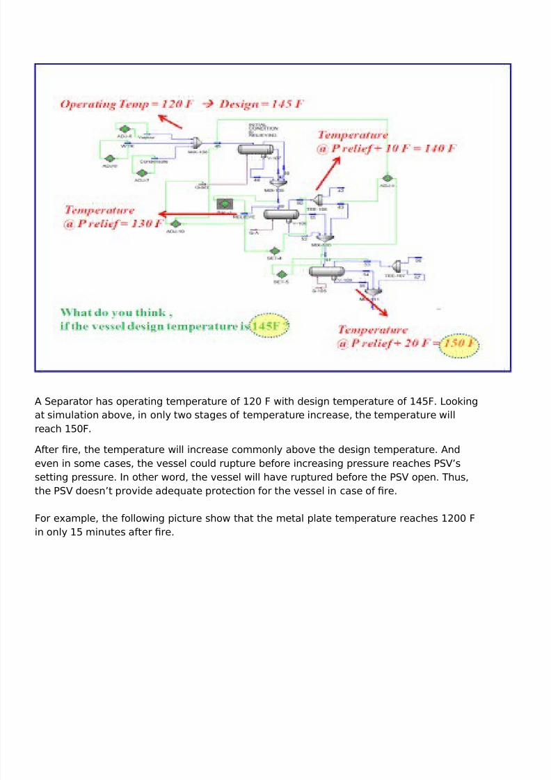
&or ammable and combustible li+uid, heat input re%ers to '&7) 1/ as %ollow.
8/10/2019 Depressuring Tutorial
http://slidepdf.com/reader/full/depressuring-tutorial 11/51
'ote <
3. In%ormation in table applies to li+uifed components 4 see original standard %ornonli+uifed gases
. C) Compressed as )ssociation
'&7) 'ational &ire 7rotection )ssociation
)'SI )merican 'ational Standard )ssociation
1.Heat Input e(pressed in =TPQhr, with area in s+uare %eet.
:.See source documents %or details o% area calculations
!y %riend, i% you want to check the correctness o% value in above table, please re%ers to
original re%erence, uidelines %or 7ressure Belie% and *uent Handling System, )!*BIC)'I'STITPT* >& CH*!IC)2 *'I'**BS #)ICH*$, Table 1.13 #page 313 o% 01U$. You can fnd
that book in our library.
)7I ST" 03 provides %ormulas %or calculating heat input rate to process vessel containing
li+uid.
V 3./// &)R/.U
5here ade+uate drainage and frefghting e+uipment do not e(ist, e+uation below should
be used,
V 1:,0// &)R/.U
Begarding a drainage, as long as the amount o% li+uid which is spilled out around the
vessel is possibly decrease, use the frst %ormula # heat u( 3///$.
& is environment %actor. The value & 3 %or bare vessel. Be%er to )7I ST" 03 Table 0
#page 3L$ %or other than bare vessel.
) is wetted area o% the vessel.

8/10/2019 Depressuring Tutorial
http://slidepdf.com/reader/full/depressuring-tutorial 12/51
The value o% ) R/.U reect that not 3//F vessel area e(posed by fre. It is true %or large
vessel, %or small vessel, we can use assumption that 3// F vessel area is totally e(posed
by fre.
&or e(ample, %or small bare vessel, the e+uation to be V 3./// ).
!y %riend, please note, based on the %ormula, when UF %raction area is applied the heat
u( is 3./// =TPQ)t*!+,Qhr or 1:0// =TPQ)t*!+,Qhr. )nd when 3//F %raction area is
applied, the unit will be =TPQ)t*.Qhr. This understanding will use%ul in per%orm
depressuring simulation using HYSYS.
The above %ormula is %or pool fre case which has heat u( o% 3./// =TPQ%t3.J:Qhr.
5hereas, based on )7I ST" 03, the heat u( %or -et fre is W0.0// =TPQ%tQhr #average$.
&rom the unit o% heat u( %or -et fre, its show that 3//F %raction area is used #%or -et fre is
localiAed heat u($.
Hope this drawing helps you get better understanding o% pool fre and -et fre
)nd below is -et fre

8/10/2019 Depressuring Tutorial
http://slidepdf.com/reader/full/depressuring-tutorial 13/51
!y %riend, in this posting we discuss about heat input rate o% fre e(posure %or process vessel. The
%ollowing are the important point,
3. &or ade+uate drainage and fre fghting e(ist, use %ormula V 3./// &)R/.U
. &or small vessel, use 3//F %raction area is e(posed by fre, there%ore V 3./// &). In my
understanding, vessel with wetted area less than // %t can be considered small vessel #see '&7)
1/$
1. &or wetted vessel, overpressure caused by li+uid evaporation, the relieving load capacity can be
calculated as heat input divided by latent heat o% vaporiAation. #5 VQHv$.
:. Heat u( o% -et fre is very high #W0.0// =TPQ%tQhr average$, and in localiAed area.
0. I suggest you to siAing 7S8 on fre case %or pool fre case only.
J. The relieving temperature can be higher than the vessel collapse temperature. 8essel will
collapse be%ore increasing pressure reach 7S8;s set pressure. There)ore/ actuall/ 0$1 doesn2t

8/10/2019 Depressuring Tutorial
http://slidepdf.com/reader/full/depressuring-tutorial 14/51
provide su3cient protection+ Depressuring is one o) the additional protections against
4re. #5e will discuss about fre case depressuring both %or pool and -et fre in other posting$
!y %riend, thank you %or reading, please correct me i% I9am 5rong.
Rigorous %ethod )or &ire Case

8/10/2019 Depressuring Tutorial
http://slidepdf.com/reader/full/depressuring-tutorial 15/51
In previous article, I have e(plained that relieving load %or fre case can be calculated as heat input
divided by latent heat o% vaporiAation. #5 VQHv$. The heat input have been discussed be%ore,
see fre case Xheat input rate. The latent heat o% vaporiAation is rather di?cult to be determined.
"uring fre, li+uid in the vessel will be vaporiAed, but the amount o% vapor %ormed is not f(ed,
because the li+uid composition is change overtime. In this article, I will e(plain you step by step the
rigorous method %or fre case
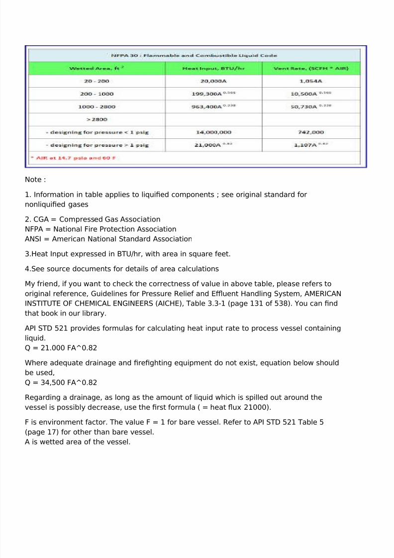
2et imagine the system consist o% a three phase separator below, the fre case calculationprocedure is as %ollow4
3. "etermine the inventory volume o% isolated system, both %or condensate, water, and gas based
on actual siAe o% the vessel and pipe.
. Calculate the wetted area.
8/10/2019 Depressuring Tutorial
http://slidepdf.com/reader/full/depressuring-tutorial 16/51
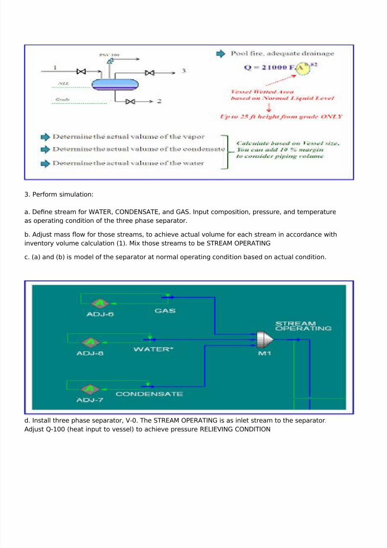
1. 7er%orm simulation<
a. "efne stream %or 5)T*B, C>'"*'S)T*, and )S. Input composition, pressure, and temperature
as operating condition o% the three phase separator.
b. )d-ust mass ow %or those streams, to achieve actual volume %or each stream in accordance with
inventory volume calculation #3$. !i( those streams to be STB*)! >7*B)TI'
c. #a$ and #b$ is model o% the separator at normal operating condition based on actual condition.
d. Install three phase separator, 8/. The STB*)! >7*B)TI' is as inlet stream to the separator.
)d-ust V3// #heat input to vessel$ to achieve pressure B*2I*8I' C>'"ITI>'
8/10/2019 Depressuring Tutorial
http://slidepdf.com/reader/full/depressuring-tutorial 17/51
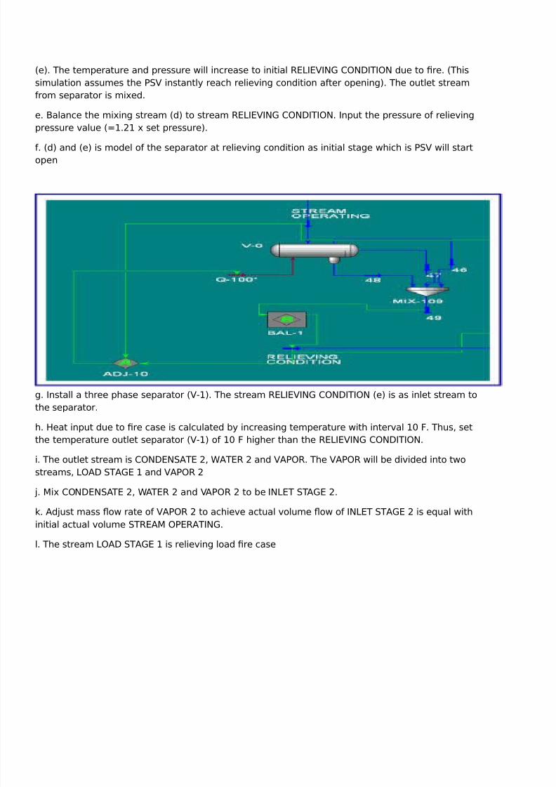
#e$. The temperature and pressure will increase to initial B*2I*8I' C>'"ITI>' due to fre. #This
simulation assumes the 7S8 instantly reach relieving condition a%ter opening$. The outlet stream
%rom separator is mi(ed.
e. =alance the mi(ing stream #d$ to stream B*2I*8I' C>'"ITI>'. Input the pressure o% relieving
pressure value #3.3 ( set pressure$.
%. #d$ and #e$ is model o% the separator at relieving condition as initial stage which is 7S8 will start
open
g. Install a three phase separator #83$. The stream B*2I*8I' C>'"ITI>' #e$ is as inlet stream to
the separator.
h. Heat input due to fre case is calculated by increasing temperature with interval 3/ &. Thus, set
the temperature outlet separator #83$ o% 3/ & higher than the B*2I*8I' C>'"ITI>'.
i. The outlet stream is C>'"*'S)T* , 5)T*B and 8)7>B. The 8)7>B will be divided into two
streams, 2>)" ST)* 3 and 8)7>B
-. !i( C>'"*'S)T* , 5)T*B and 8)7>B to be I'2*T ST)* .
k. )d-ust mass ow rate o% 8)7>B to achieve actual volume ow o% I'2*T ST)* is e+ual with
initial actual volume STB*)! >7*B)TI'.
l. The stream 2>)" ST)* 3 is relieving load fre case

8/10/2019 Depressuring Tutorial
http://slidepdf.com/reader/full/depressuring-tutorial 18/51
m. The heat input to 83 in HYSYS simulation is V3 =TPQhr, whereas the actual heat input is V )7I 3./// & ) R/.U =TPQhr
n. Calculate the re+uired time o% increasing temperature at stage 3, that Is #V3$ Q #3./// &.)
R/.U$
o. Install a three phase separator 8. The stream I'2*T ST)* is as inlet stream to the separator.
p. Bepeat the procedure %rom #g$ to #n$, %or stage , stage 1, stage : ....with temperature is
increased by 3/& in every stage. 5e can stop the procedure i% the cumulative time is one hour #it;s
assumed that the fre has been suppressed during 3 hr, you can use more than 3 hour i% you want$
+. Calculate the re+uired area %or each stage, #with the relieving load are 2>)" S)T* 3, 2>)"
ST)* , 2>)" ST)* 1, $
r. Pse the stage re+uiring the ma(imum orifce area as basis datasheet o% the 7S8.
fnish <"
ood morning my %riend, That9s all I can share today, I;m very happy today because I fnd a new
spirit %or better li%e. "on9t regret what was loss4 it didn9t disappear actually, -ust in use by more
appropriate user to make it more use%ul thing. Sometimes we lose something, but at the same time,
we get the other thing that better, at least a lesson.
Hope%ully you never bored with my article.
Thank %or reading,

8/10/2019 Depressuring Tutorial
http://slidepdf.com/reader/full/depressuring-tutorial 19/51
0$1 Calculation - 5d/5c/56 )actor
Hi %riends, how are you today6 Hope%ully, you are not already bored with my articles. 'ow,
we will learn the concept o% relie% valve calculation. The spreadsheets not tell you
anything, but we should know what really it does. )%ter read this %ully article, I hope you
get a better understanding o% the relie% valve calculation concept, and then know well with
your spreadsheet.
7ressure is e+ual to the %orce divided by the area #7Z&Q)$. That is a very basic concept. I
am sure you already %amiliar with this %ormula in the very beginning o% -unior high school.
In talking 7S8, the %orce is generated by mass relieving rate. I am sure, all o% us know well
that relieving rate is depends on cases that to be considered #e.g. fre, blocked discharge,
gas blow by etc.$
5e need some corrections since the uid ows through a relie% valve noAAle orifce rather
than an ideal noAAle. &or the same area, at certain condition, the ow capacity o% relie%
valve orifce must be less compared with the ideal one X Its mean that more area is
re+uired to handle the same mass relieving rate . That;s why, there are some correction
%actors are re+uired such as4 [c, [d, [b, [v, [p, [h, [n etc.
2et;s %ocus to [c, [d and [b. I will make other posting %or the e(planation o% the other
%actors.
E7ective Discharge 8 5d
[d is eective discharge coe?cient used %or the mass u( capacity correction %or the real
noAAle. The higher the [d value, the closer the mechanical to an ideal design ideal
noAAle, [d 3. It is very obvious that the 7S8 has [d value lower than 3. &or instance, )7I
relie% valve has [d /.WL0 and /.J0 %or gas and li+uid respectively.
8/10/2019 Depressuring Tutorial
http://slidepdf.com/reader/full/depressuring-tutorial 20/51
[d is depends on the mechanical design. In other word, every vendor has a specifc value
o% [d. It is important to be realiAed, so you are not always input /.WL0 in the spreadsheet
whereas you use 7S8 other than )7I.
5e can use )7I data as preliminary calculation only when we don;t have any re%erence o%[d value. 5e usually do this at proposal stage.
Some vendors have a better design 7S8 than standard )7I. In other word, they have [d
value higher than /.WL0. So, I suggest you to ask your vendor the e(act value o% [d,
especially at pro-ect stage. There is potential that the smaller orifce area is re+uired.
Com6ination with Rupture Dis9 8 5c
[c is correction %actor when rupture disk to be installed upstream o% the 7S8.
Bupture disk is re+uired to be installed at upstream o% the 7S8 %or system contain solid
that may plug the 7S8 over time. )t H)EI"QH)E>7, %or to(ic service, potential leaking o%relie% valve shall be considered, and then rupture disk at upstream 7S8 can be used as
positive seal %or the sa%eguard. That is why, based on my e(perience, the combination
rupture disk and 7S8 is very seldom to be applied in the gas processing.
)ctually, the [c value is comple(. =ut I am sure, we seldom use it. So, I am not too interest
makes longer e(planation. I understand many engineers hate with the long article with
something not practical, me too. I% you want to know more detail about [c, please read )7I
0/ part I by yoursel%.
(mpact o) Bac9 0ressure 8 56
=ack pressure is defned as a pressure e(isting at 7S8;s outlet. It impact to opening
pressure, reduction capacity, instability or may combination o% all. [b is re+uired %or
correction o% reducing capacity.
&or the low back pressure system that the impact is not signifcant, conventional type can
be used. )nd %or the e(cessive back pressure service, pilot type 7S8 is re+uired to
overcome it. Then, imagine that low back pressure %or the conventional type and no
impact back pressure on pilot type due to mechanical design. That;s all, I think, very clear
why [b is re+uired %or balance below type only.
'ote that the back pressure correction %actor [b %or conventional and pilot type is not
re+uired, and then use [b3. )sk your vendor o% [b value Xas graphic %or using below
7S8 type or re%er to )7I 0/ part 3 %or preliminary design.
)ctually, %or conventional type, when the condition is noncritical due to superimposed
back pressure, [b is re+uired. =ut %or now, rather than it will make you con%use, %orget it
since there are not much system likes that.

8/10/2019 Depressuring Tutorial
http://slidepdf.com/reader/full/depressuring-tutorial 21/51

8/10/2019 Depressuring Tutorial
http://slidepdf.com/reader/full/depressuring-tutorial 22/51
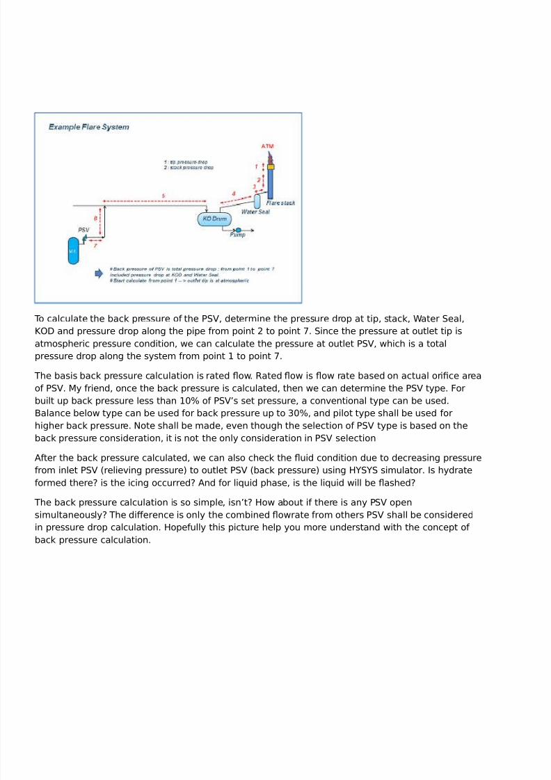
In this e(planation I use a general are system which the disposal is discharged to atmosphere via
are stack. 2et imagine, when relie% valve open, relieving uid ow thru Tail 7ipe XSub Header X
!ain Header&lare "rumSeal 5ater "rum X &lare Stack X &lare Tip and fnally discharged to
atmosphere at certain height # %or sa%e disposal purpose$
The =uilt up back pressure can be calculated by count up total pressure drop at the pipe, drum,
stack and tip. Start calculation %rom the pressure drop at the tip, then at stack until tail pipe o% the
relie% valve. The built up back pressure is pressure that e(ist at outlet relie% valve # that is same as
with total pressure drop %rom the tail pipe to the are tip$
&or more clear, see this picture below
To calculate the back pressure o% the 7S8, determine the pressure drop at tip, stack, 5ater Seal,
[>" and pressure drop along the pipe %rom point to point L. Since the pressure at outlet tip is
atmospheric pressure condition, we can calculate the pressure at outlet 7S8, which is a total
pressure drop along the system %rom point 3 to point L.
The basis back pressure calculation is rated ow. Bated ow is ow rate based on actual orifce area
o% 7S8. !y %riend, once the back pressure is calculated, then we can determine the 7S8 type. &or
built up back pressure less than 3/F o% 7S8;s set pressure, a conventional type can be used.
=alance below type can be used %or back pressure up to 1/F, and pilot type shall be used %orhigher back pressure. 'ote shall be made, even though the selection o% 7S8 type is based on the
back pressure consideration, it is not the only consideration in 7S8 selection
)%ter the back pressure calculated, we can also check the uid condition due to decreasing pressure
%rom inlet 7S8 #relieving pressure$ to outlet 7S8 #back pressure$ using HYSYS simulator. Is hydrate
%ormed there6 is the icing occurred6 )nd %or li+uid phase, is the li+uid will be ashed6

8/10/2019 Depressuring Tutorial
http://slidepdf.com/reader/full/depressuring-tutorial 23/51
The back pressure calculation is so simple, isn;t6 How about i% there is any 7S8 open
simultaneously6 The dierence is only the combined owrate %rom others 7S8 shall be considered
in pressure drop calculation. Hope%ully this picture help you more understand with the concept o%
back pressure calculation.
See the picture above. I will e(plain you why the calculation o% built up back pressure is very
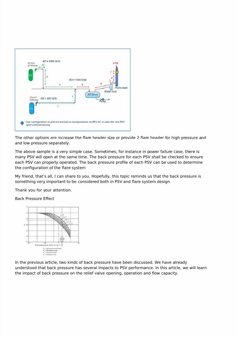
important not only %or 7S8 design but also %or are system design. 2et imagine4
7S8 /3 is set at 0/ psig with relieving ow o% // lbQhr.
7S8 / is set at 3// psig with relieving ow o% 3/// lbQhr.
In case the two 7S8 open simultaneously, what do you think what happen with the 7S8 /3 i% the
back pressure o% 7S8 / is more than 0/ psig6 >% course the 7S8 /3 cannot open properly
5hat is the solution6 Hmm,, look at this picture, it will show you a better confguration o% are
header system to avoid that condition
8/10/2019 Depressuring Tutorial
http://slidepdf.com/reader/full/depressuring-tutorial 24/51
The other options are increase the are header siAe or provide are header %or high pressure and
and low pressure separately.
The above sample is a very simple case. Sometimes, %or instance in power %ailure case, there is
many 7S8 will open at the same time. The back pressure %or each 7S8 shall be checked to ensure
each 7S8 can properly operated. The back pressure profle o% each 7S8 can be used to determine
the confguration o% the are system
!y %riend, that;s all, I can share to you. Hope%ully, this topic reminds us that the back pressure issomething very important to be considered both in 7S8 and are system design
Thank you %or your attention.
=ack 7ressure *ect
In the previous article, two kinds o% back pressure have been discussed. 5e have already
understood that back pressure has several impacts to 7S8 per%ormance. In this article, we will learn
the impact o% back pressure on the relie% valve opening, operation and ow capacity.
8/10/2019 Depressuring Tutorial
http://slidepdf.com/reader/full/depressuring-tutorial 25/51
!y %riend, I% you don;t have a good understanding on the defnition o% terminology such as4
overpressure, accumulation, set pressure, re seat pressure etc, I guest you will be con%used with my
e(planation. In this article, I won;t to e(plain each o% them, so please re%er to )7I 0/ part I by your
sel%. It;s very important to understand the meaning o% its defnition.
7B*SSPB* B*2I*& 8)28* >7*'I'
Superimposed back pressure has impact to opening o% conventional relie% valve type. This back
pressure will give additional spring %orce onto valve disk in closed position. There%ore, the actual
spring setting can be reduced by an amount e+ual to the amount o% superimposed back pressure.
Hope%ully, this picture will help us.
&or balance and pilot type, the compensation o% the constant superimposed back pressure is not
re+uired
7B*SSPB* B*2I*& 8)28* >7*B)TI>'
*(cessive o% built up back pressure has impact the conventional valve operates in unstable
condition. Its may be chatter or utter. Chatter is rapid motion o% closing and opening valve where
the disc contacts with the relie% valve seat during cycling, whereas utter is not contact with the
seat. Chatter cause damage to the valve.
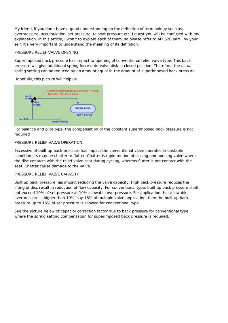
7B*SSPB* B*2I*& 8)28* C)7)CITY
=uilt up back pressure has impact reducing the valve capacity. High back pressure reduces the
li%ting o% disc result in reduction o% ow capacity. &or conventional type, built up back pressure shall
not e(ceed 3/F o% set pressure at 3/F allowable overpressure. &or application that allowable
overpressure is higher than 3/F, say 3JF o% multiple valve application, then the built up back
pressure up to 3JF o% set pressure is allowed %or conventional type.
See the picture below o% capacity correction %actor due to back pressure %or conventional type
where the spring setting compensation %or superimposed back pressure is re+uired.
8/10/2019 Depressuring Tutorial
http://slidepdf.com/reader/full/depressuring-tutorial 26/51
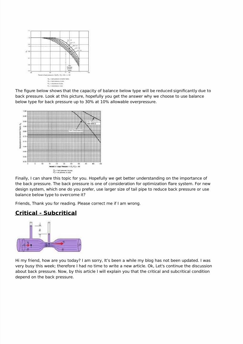
The fgure below shows that the capacity o% balance below type will be reduced signifcantly due to
back pressure. 2ook at this picture, hope%ully you get the answer why we choose to use balance
below type %or back pressure up to 1/F at 3/F allowable overpressure.
&inally, I can share this topic %or you. Hope%ully we get better understanding on the importance o%
the back pressure. The back pressure is one o% consideration %or optimiAation are system. &or new
design system, which one do you pre%er, use larger siAe o% tail pipe to reduce back pressure or use
balance below type to overcome it6
&riends, Thank you %or reading. 7lease correct me i% I am wrong.
Critical - $u6critical
Hi my %riend, how are you today6 I am sorry, It;s been a while my blog has not been updated. I was
very busy this week4 there%ore I had no time to write a new article. >k, 2et9s continue the discussion
about back pressure. 'ow, by this article I will e(plain you that the critical and subcritical condition
depend on the back pressure.

8/10/2019 Depressuring Tutorial
http://slidepdf.com/reader/full/depressuring-tutorial 27/51
=e%ore I make %urther e(planation, please note, e(planation in this article will be limited %or gas
vapor phase application only.
)7I 0/ part 3 provides calculation procedure %or siAing o% eective area. The procedure is divided
to critical and subcritical condition that depends on the back pressure that e(ists at outlet 7S8.
Critical condition is considered when the back pressure is lower than the critical ow pressure.
Critical &low Rate
How critical condition occurred6 I% a compressible gas is e(panded across a noAAle or orifce, at
constant upstream condition, its velocity increases with the decreasing downstream pressure. The
increasing velocity means that the mass ow rate increases. The ow rate will increase until a
limiting value.
)t sonic velocity, the ow rate could never increase anymore even though the downstream
pressure is much lower. This ma(imum ow rate at sonic velocity is known as critical ow rate.
see this picture.
Critical &low 0ressure
To avoid con%usion, terminology o% critical ow pressure is used instead o% critical pressure. Critical
ow pressure is defned as an absolute pressure at noAAle e(it at critical ow rate. The actual
pressure at noAAle e(it cannot %all below the critical ow pressure even though the downstream
pressure is much lower

8/10/2019 Depressuring Tutorial
http://slidepdf.com/reader/full/depressuring-tutorial 28/51
Critical ow pressure can be calculated using the ideal gas relationship.
See above fgure. &or 7S8, pressure at outlet is known as back pressure. =ased on the back
pressure value, we can determine whether the condition is critical or subcritical.
Critical condition is considered i% the back pressure is less than the critical ow pressure. In other
word, i% the back pressure is greater than the critical ow pressure, it will be considered as
subcritical condition.
The orifce calculation procedures both %or critical and sub critical condition shall be used in eachappropriate condition.
!y %riend, that;s all, I can share to you. Critical and subcritical condition depend on the back
pressure. Hope%ully, this topic reminds us that the back pressure is something very important to be
considered when we conduct 7S8 siAing.
Thank you %or your attention.
8/10/2019 Depressuring Tutorial
http://slidepdf.com/reader/full/depressuring-tutorial 29/51
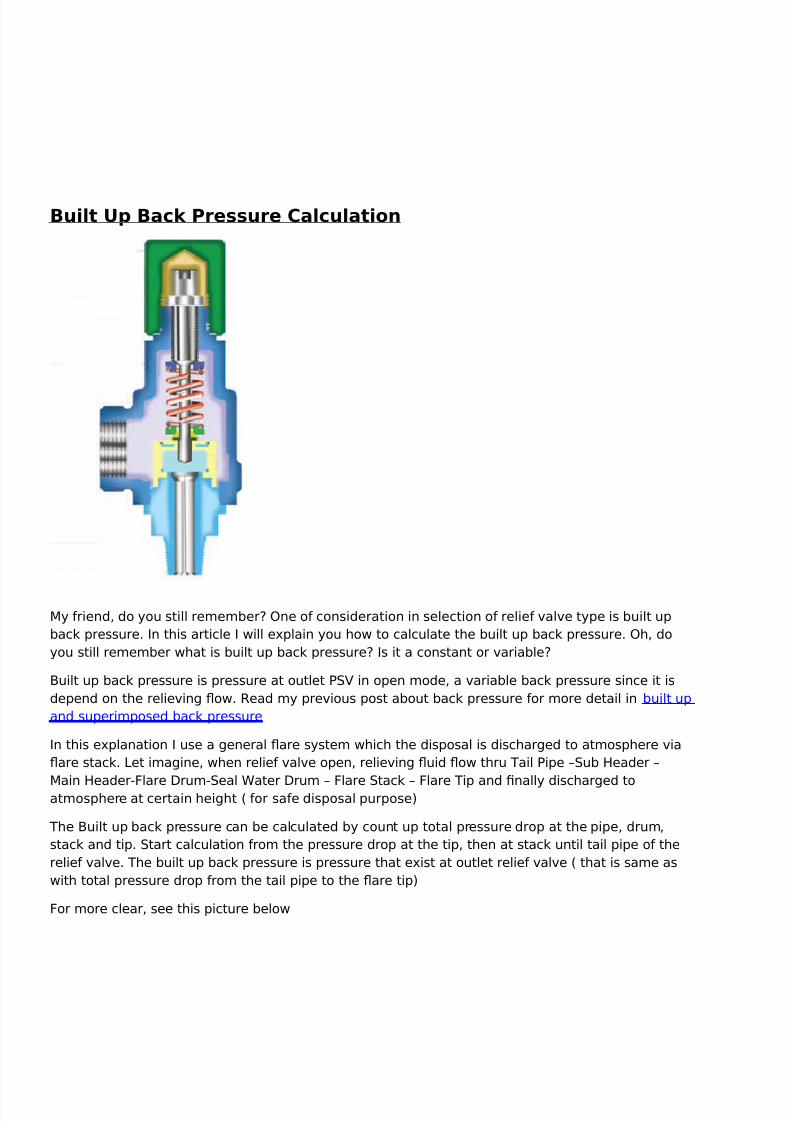
Built :p Bac9 0ressure Calculation
!y %riend, do you still remember6 >ne o% consideration in selection o% relie% valve type is built up
back pressure. In this article I will e(plain you how to calculate the built up back pressure. >h, do
you still remember what is built up back pressure6 Is it a constant or variable6
=uilt up back pressure is pressure at outlet 7S8 in open mode, a variable back pressure since it is
depend on the relieving ow. Bead my previous post about back pressure %or more detail in built up
and superimposed back pressure
In this e(planation I use a general are system which the disposal is discharged to atmosphere via
are stack. 2et imagine, when relie% valve open, relieving uid ow thru Tail 7ipe XSub Header X
!ain Header&lare "rumSeal 5ater "rum X &lare Stack X &lare Tip and fnally discharged toatmosphere at certain height # %or sa%e disposal purpose$
The =uilt up back pressure can be calculated by count up total pressure drop at the pipe, drum,
stack and tip. Start calculation %rom the pressure drop at the tip, then at stack until tail pipe o% the
relie% valve. The built up back pressure is pressure that e(ist at outlet relie% valve # that is same as
with total pressure drop %rom the tail pipe to the are tip$
&or more clear, see this picture below
8/10/2019 Depressuring Tutorial
http://slidepdf.com/reader/full/depressuring-tutorial 30/51
To calculate the back pressure o% the 7S8, determine the pressure drop at tip, stack, 5ater Seal,
[>" and pressure drop along the pipe %rom point to point L. Since the pressure at outlet tip is
atmospheric pressure condition, we can calculate the pressure at outlet 7S8, which is a total
pressure drop along the system %rom point 3 to point L.
The basis back pressure calculation is rated ow. Bated ow is ow rate based on actual orifce area
o% 7S8. !y %riend, once the back pressure is calculated, then we can determine the 7S8 type. &or
built up back pressure less than 3/F o% 7S8;s set pressure, a conventional type can be used.
=alance below type can be used %or back pressure up to 1/F, and pilot type shall be used %or
higher back pressure. 'ote shall be made, even though the selection o% 7S8 type is based on the
back pressure consideration, it is not the only consideration in 7S8 selection
)%ter the back pressure calculated, we can also check the uid condition due to decreasing pressure
%rom inlet 7S8 #relieving pressure$ to outlet 7S8 #back pressure$ using HYSYS simulator. Is hydrate
%ormed there6 is the icing occurred6 )nd %or li+uid phase, is the li+uid will be ashed6
The back pressure calculation is so simple, isn;t6 How about i% there is any 7S8 open
simultaneously6 The dierence is only the combined owrate %rom others 7S8 shall be considered
in pressure drop calculation. Hope%ully this picture help you more understand with the concept o%
back pressure calculation.

8/10/2019 Depressuring Tutorial
http://slidepdf.com/reader/full/depressuring-tutorial 31/51

8/10/2019 Depressuring Tutorial
http://slidepdf.com/reader/full/depressuring-tutorial 32/51
The other options are increase the are header siAe or provide are header %or high pressure and
and low pressure separately.
The above sample is a very simple case. Sometimes, %or instance in power %ailure case, there is
many 7S8 will open at the same time. The back pressure %or each 7S8 shall be checked to ensure
each 7S8 can properly operated. The back pressure profle o% each 7S8 can be used to determine
the confguration o% the are system
!y %riend, that;s all, I can share to you. Hope%ully, this topic reminds us that the back pressure issomething very important to be considered both in 7S8 and are system design
Thank you %or your attention.
0$1 (nstallation-;uide

8/10/2019 Depressuring Tutorial
http://slidepdf.com/reader/full/depressuring-tutorial 33/51
!y %riend, 2et me share a simple material about 7S8 installation. However it will only %ocus on
designing the system. This is become my frst posting in this year. Hope%ully, this material is use%ul
%or you in developing the system around 7S8.
!y %riends, in developing or reviewing the 7\I", especially in 7S8 system, please consider the
%ollowing 4
!+ 0$1 normall 6e installed close to protected e<uipment+
The sa%ety valve is installed %or protecting the e+uipment, so that the closer to the e+uipment is
better. &or e(ample, %rom sa%ety point o% view, to install the 7S8 directly at vessel is better than at
line outlet vapor.
. 7S8 %or vapor application at vessel shall be connected to the vessel in the vapor space higher
than HH22.
1. () an demister/ 0$1 shall 6e connected to the vessel at 6elow the demister since there
is any potential blockage o% demister, and i% the 7S8 be installed at downstream demister, it willnot protect the vessel in that case.
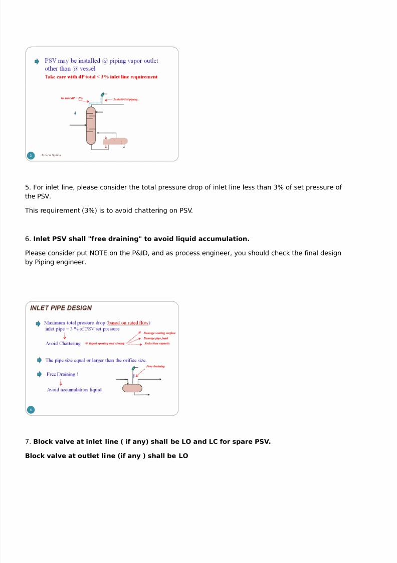
:. 7S8 may be installed at outlet vapor line. &or this case, take care with the 1F pressure drop
limitation.
8/10/2019 Depressuring Tutorial
http://slidepdf.com/reader/full/depressuring-tutorial 34/51
0. &or inlet line, please consider the total pressure drop o% inlet line less than 1F o% set pressure o%
the 7S8.
This re+uirement #1F$ is to avoid chattering on 7S8.
J. (nlet 0$1 shall =)ree draining= to avoid li<uid accumulation+
7lease consider put '>T* on the 7\I", and as process engineer, you should check the fnal design
by 7iping engineer.
L. Bloc9 valve at inlet line > i) an? shall 6e @A and @C )or spare 0$1+
Bloc9 valve at outlet line >i) an ? shall 6e @A

8/10/2019 Depressuring Tutorial
http://slidepdf.com/reader/full/depressuring-tutorial 35/51
U. i% discharged to )T! # please indicate on 7\I" )S2 #at sa%e location$ instead o% )T!$. The block
valve is not re+uired. The weep hole to 6e provided at lowest point o) discharge pipe to
drain the li<uid+
W. >utlet line to be designed with !ach 'o ] /.L
Check the momentum # Bho v $ i% the value o% #Bho v$ ^ //./// 7a..please take care since it
may be vibration. Psually 7iping engineer will also check the re+uirement o% piping support.
=ack pressure to be considered based on 7S8 type.
'oise %or emergency case typically more than U0 d= is still accepted.
Check the two phase ow pattern, i% there is any slug ow please take care, you must state in the
7\I" so that 7iping *ngineer will consider the strengthening o% support.

8/10/2019 Depressuring Tutorial
http://slidepdf.com/reader/full/depressuring-tutorial 36/51
3/. >utlet line shall onl have downward elevation change to the are subheader.
33. Consider minimum distance )rom 6 pass 6loc9 valve to discharge line )or heav
hdrocar6on service+
3. @ateral connection to 6e designed with " deg or deg to the header+
31 7lease consider, >ther system may have specifc re+uirement. Think about it by yoursel%.

8/10/2019 Depressuring Tutorial
http://slidepdf.com/reader/full/depressuring-tutorial 37/51
I think that all, that I can share to you by today.
!y %riend, how are you today6 It;s been long time I don;t update my blog, really sorry guys. I was
very busy doing my pro-ect X urea plant in 7alembang. Thank you very much %or many o% you
who9ve contacted me via email and give me %eedback and muchmuch spirit %or me to keep
updating this blog Nagain;
Bloc9 Autlet Case
!y %riend, regarding the overpressure protection system design, one o% important responsibility %or
process engineer is determining the cause o% overpressure. In this posting, we will discuss whether
a kind o% case is possible occurred.
There are many causes o% overpressure. *very possible overpressure condition shall be reviewed to
ensure overpressure protection device capacity is ade+uate to protect the system. The %ollowing
picture presents the causes o% overpressure.

8/10/2019 Depressuring Tutorial
http://slidepdf.com/reader/full/depressuring-tutorial 38/51
!y %riend, let discuss how block outlet is applicable to be considered.
#other cases in ne(t posting.$
B@AC5ED A:T@ET
&or review whether this case applicable or not, check < is there any valve that possible closed6 >r
any control valves which is N%ail to close; position6 is there any ob-ect that possible block the uid
ow 6 I% Y*S, it may be blocked and lead to pressure increase.
The re+uired load capacity o% 7S8 can be determined based on the mass balance in the system
a%ter block outlet occurred.
Here is -ust simple case.

8/10/2019 Depressuring Tutorial
http://slidepdf.com/reader/full/depressuring-tutorial 39/51
&or system which comprises o% many vessel Q separator with same design pressure, block outlet
case is only considered %or 7S8 in the most upstream location. 5hen block outlet occurred at
downstream the system pressure increase lead to open 7S8 at the upstream.
I think, it is better to e(plain by this picture
There%ore, %or system with same design pressure, the block outlet only applicable %or one 7S8 only.
!y %riend, that;s all, I can share to you today. Hope%ully, this simple article use%ul %or you.

8/10/2019 Depressuring Tutorial
http://slidepdf.com/reader/full/depressuring-tutorial 40/51
Beu( &ailure Case
Beu( %ailure case is the ma-or case o% all tower or column. Beu( %ailure can be caused by the
%ollowing<
7ower %ailure lead to reu( pump o
7ump %ailure Control valve %ailure # %ail closed or stuck closed$
>perator error etc
5hen reu( pump %ail, there no reu( ow inlet to column. =asically the reu( ow is own back to
column #at recti%ying section$ to increase separation e?ciency. >ther that, the reu( ow is use%ul
also %or cooling the vapor ow to the top o% the column. Beu( pump %ailure cause N2oss o% Cooling;,
as a conse+uence, the vapor temperature will not be cooled down and overpressure will occur.
Control valve %ailure has same eect as a pump %ailure.
7ower %ailure case cause trip o% the air cooler, cooling %ailure and overpressure will occur.
=ased on my e(perience, the simplifcation o% the calculation load capacity %or reu( %ailure has
been made. ndtray vapor ow is assumed as basis load capacity. In HYSYS, the column model

8/10/2019 Depressuring Tutorial
http://slidepdf.com/reader/full/depressuring-tutorial 41/51
never convergent i% the reu( ow /, there%ore in HYSYS simulation, input reu( ow with very
small number. )%ter column model convergent, we can use nd tray vapor ow as load capacity o%
the 7S8.
)ctually, the determining load capacity o% reu( %ailure is very comple(. 2et imagine, once the
pressure increase in the column, the boiling point o% uid in the reboiler increase, the number o%
vapor will decrease. It has many eects to separation and e+uilibrium condition.
I have %ound much discussion regarding reu( %ailure case, especially the method %or determining
load capacity. Pn%ortunately, until now, there is no agreement reached, no method f(ed, there%ore I
can;t make a -ustifcation which one is the best approach %or calculating load capacity %or reu(
%ailure.
7lease %ollow the %ollowing link %or more discussion about reu( %ailure
3."iscussion 3 %rom Cheresources
."iscussion %rom Cheresources
1.) sample dynamic method %or determining load capacity reu( %ailure
!y %riend, please share to me i% you have other method %or calculating load capacity %or reu(%ailure case
Thank %or reading, hope%ully this posting use%ul %or you
Tube Bupture Case
Tube rupture may be occurred %or shell and tube heat e(changer type. =ased on my e(perience,
some design philosophy using Q1 rule, and some other using 3/Q31 rule %or the criteria o%re+uirement 7S8 %or tube rupture. 5hich one is correct6 Should we apply Q1 or 3/Q31 rule6
Tube rupture is possible cause overpressure in shell and tube heat e(changer type i% Test 7ressure
o% 2ow 7ressure Side 2*SS than design pressure o% High 7ressure Side. That is where Q1 and 3/Q31
rule coming %rom. &or e+uipment with test pressure 3, 0 ( design pressure, the Q1 #3/Q30$ rule
is applied, whereas %or test pressure 3, 1 ( design pressure, the 3/Q31 rule is applied

8/10/2019 Depressuring Tutorial
http://slidepdf.com/reader/full/depressuring-tutorial 42/51

8/10/2019 Depressuring Tutorial
http://slidepdf.com/reader/full/depressuring-tutorial 43/51
Blowdown 0$1
I can9t sleep again, till this midnight , almost //.// 7! #or )! 6 $, I -ust con%use what to do. I think it
will better %or me to do something use%ul. =ut what 6 I don9t get any idea. Pntil fnally, I remember
this blog.
!y blog save my brain <".
Psually, when I don9t know what to do, the most o%ten I decide is check my %acebook, -ust want to
know my %riend9s status.

8/10/2019 Depressuring Tutorial
http://slidepdf.com/reader/full/depressuring-tutorial 44/51
>h !y od,,why I share my %eeling to you.,I should share my knowledge instead o% my %eeling, right
6 I am so sorry.
!y %riend,there are many terminology related to 7S8. I give you a summary as %ollowing picture.
7lease comment to this posting %or only item which you don9t understand <",
I will answer your +uestion later.
ho,, ho,, sorry %or this disappointed posting,,hope%ully you understand me, I am a%raid will make
many mistakes e(planation in this midnight.
>kay,,I give one item only. I will e(plain you about =2>5">5'.
=lowdown is dierential pressure #can be in percentage$ between set pressure and re-seat
pressure. 0$1 start to open at set pressure and will ! 6ac9 closed at re-seat
pressure. 5hat do you think, why the re seat pressure lower than set pressure 6 and 5hat impact
blowdown value to 7S89s operation 6
See the picture below
)nd this picture below will show why the re seat pressure is lower than set pressure.

8/10/2019 Depressuring Tutorial
http://slidepdf.com/reader/full/depressuring-tutorial 45/51

8/10/2019 Depressuring Tutorial
http://slidepdf.com/reader/full/depressuring-tutorial 46/51
>ne o% the eects o% gas blow by can be overpressure in a downstream component. >% course, the
low level is the detectable condition that indicates gas blowby may be occurred.
This picture below show gas blowby case
&or instance in a separator system, to determine whether this case applicable or not, check design
pressure o% the e+uipment in downstream control valve. I% the design pressure is e+ual, the gas
blowby will not cause overpressure in the downstream e+uipment. Conversely, I% the design
pressure o% the downstream e+uipment is lower than the upstream e+uipment, when control valve
%ail, the gas will ow to the downstream e+uipment and cause overpressure.
Please note, gas blowby case is applicable if only the design pressure of downstream equipment
lower than the upsteam pressure.
The re+uired load capacity o% 7S8 can be determined based on the mass balance in the system
a%ter control valve %ail is occurred.
Here is -ust simple case.

8/10/2019 Depressuring Tutorial
http://slidepdf.com/reader/full/depressuring-tutorial 47/51
The most o%ten +uestions which is raised by new process engineer in calculation load capacity gas
blowby is the %ormula %or determining the ma(imum ow through the control valve
The ma(imum ow through control valve is depends on the control valve Cv and the pressure drop
across the control valve. The %ollowing picture show an e(ample %ormula %rom one o% control valve
8endor4 please note, each 8endor has their own %ormula that might dierent in each other. I give
this %ormula to show you what the variable that has aect to owrate through the control valve
!y %riend, %or detail calculation in pro-ect stage, I suggest you to use I'STBPC)2 so%tware %or
determining the ma(imum ow through the control valve.
)%ter the ma(imum ow through control valve is calculated, the re+uired capacity o% 7S8 at
downstream e+uipment can be calculated #%or simple, 2oad !a(imum ow stream 1 X 'ormal
ow stream :$
8/10/2019 Depressuring Tutorial
http://slidepdf.com/reader/full/depressuring-tutorial 48/51
Thank you %or reading my %riend, that;s all I can share to you today. Correct me i% I am wrong
Selamat liburan pan-ang <" , semoga ada pencerahan hidup yg berman%aat yang kita dapatkan... #
don9t know how to e(press this in english <"$
0$1 $iing

8/10/2019 Depressuring Tutorial
http://slidepdf.com/reader/full/depressuring-tutorial 49/51
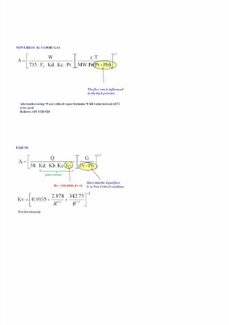
SiAing o% pressure relie% valve is clearly e(plained in )7I ST" 0/ part 3. Some %ormula is provided
%or calculation the orifce siAe either %or vapor or li+uid application, critical or non critical condition.
!y %riend, there is no di?cult thing in siAing 7S8 as long as all data re+uired is already provided.
The all we need is -ust inputting the data in the %ormula or in the spreadsheet <" , then select the
appropriate standard orifce siAe # re%er to )7I ST" 0J$
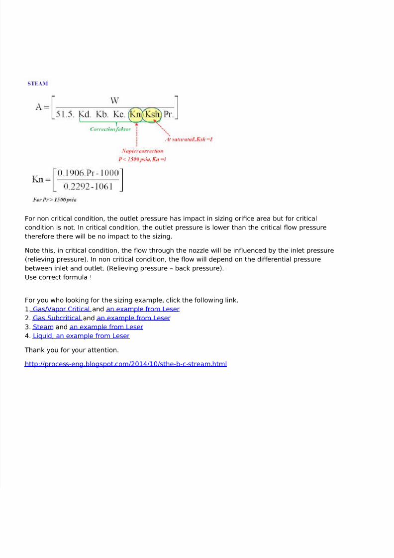
The %ollowing pictures, show the %ormula in )7I ST" 0/
8/10/2019 Depressuring Tutorial
http://slidepdf.com/reader/full/depressuring-tutorial 50/51
8/10/2019 Depressuring Tutorial
http://slidepdf.com/reader/full/depressuring-tutorial 51/51
&or non critical condition, the outlet pressure has impact in siAing orifce area but %or critical
condition is not. In critical condition, the outlet pressure is lower than the critical ow pressure
there%ore there will be no impact to the siAing.
'ote this, in critical condition, the ow through the noAAle will be inuenced by the inlet pressure
#relieving pressure$. In non critical condition, the ow will depend on the dierential pressure
between inlet and outlet. #Believing pressure X back pressure$.
Pse correct %ormula D
&or you who looking %or the siAing e(ample, click the %ollowing link.
3. asQ8apor Critical and an e(ample %rom 2eser
. as Subcritical and an e(ample %rom 2eser
1. Steam and an e(ample %rom 2eser
:. 2i+uid, an e(ample %rom 2eser
Thank you %or your attention.
http<QQprocesseng.blogspot.comQ/3:Q3/Qsthebcstream.html


![Tutorial Depressuring First [Compatibility Mode]](https://img.pdfslide.net/doc/110x75/545d5781b1af9f410a8b4af3/tutorial-depressuring-first-compatibility-mode.jpg)


![Tutorial Depressuring Second [Compatibility Mode]](https://img.pdfslide.net/doc/110x75/545531f1b1af9f9d7f8b4b91/tutorial-depressuring-second-compatibility-mode-55844dfd1d8c7.jpg)