Embed Size (px)
Citation preview
lable at ScienceDirect
Journal of Power Sources 268 (2014) 121e128
Contents lists avai
Journal of Power Sources
journal homepage: www.elsevier .com/locate/ jpowsour
Description and performance of a novel aqueous all-copper redox flowbattery
Laura Sanz a, b, *, David Lloyd a, Eva Magdalena b, Jesús Palma b, Ky€osti Kontturi a
a Aalto University, Department of Chemistry, Espoo, Finlandb Institute IMDEA Energy, M�ostoles, Madrid, Spain
h i g h l i g h t s
� A novel, aqueous chemistry based on copper for use in redox flow cells is presented.� Comparable energy density to vanadium systems due to high solubility of copper (3 M).� Uses low cost, less toxic, easily recyclable and abundant materials.� Simplicity: single step preparation of electrolyte and no catalysts required.� Elimination of heat exchangers since the operational temperature range is extended.
a r t i c l e i n f o
Article history:Received 31 January 2014Received in revised form16 May 2014Accepted 3 June 2014Available online 12 June 2014
Keywords:Redox flow batteriesAqueous electrolytesCopper-chloride complexesCost reductionHybrid flow cells
* Corresponding author. Institute IMDEA EnergyTel.: þ34 646369231.
E-mail addresses: [email protected], laurasanzruimdea.org (L. Sanz), [email protected] (D. Lloyd).
http://dx.doi.org/10.1016/j.jpowsour.2014.06.0080378-7753/© 2014 Elsevier B.V. All rights reserved.
a b s t r a c t
In this paper we present a novel aqueous redox flow battery chemistry based on copper chloro com-plexes. The energy density (20 Wh L�1) achieved is comparable to traditional vanadium redox flowbatteries. This is due to the high solubility of copper (3 M), which offsets the relatively low cell potential(0.6 V). The electrolyte is cheap, simple to prepare and easy to recycle since no additives or catalysts areused. The stack used is based on plain graphite electrode materials and a low-cost microporous separator.The system can be operated at 60 �C eliminating the need for a heat exchanger and delivers an energyefficiency of 93, 86 and 74% at 5, 10 and 20 mA cm�2 respectively.
© 2014 Elsevier B.V. All rights reserved.
1. Introduction
The growing demand for electricity expected during the comingdecades has increased interest in the development of new tech-nologies for energy production from renewable power sources,such as wind and solar. However, the success of these newrenewable power sources needs to be coupled with the introduc-tion of competitive energy storage devices for load-levelling andpeak-shaving such that these renewable sources could be tied tothe grid. In this fashion, the problem of the unpredictable andintermittent energy production behaviour of renewable powersources may be overcome. For electrical energy storage,
, M�ostoles, Madrid, Spain.
[email protected], laura.sanz@
electrochemical devices such as batteries and supercapacitors havebeen shown to provide higher efficiencies compared to other en-ergy storage systems currently utilized [1,2].
Within the wide variety of electrochemical devices for energystorage, redox flow batteries (RFB) are one of the best options formassive storage due to their higher capacity for massive storage incomparison with other battery technologies. RFBs typically employtwo soluble redox couples at high concentrations in aqueous ororganic media which are stored in two external tanks and pumpedinto an electrochemical reactor, where one of the species of theredox couple is transformed into the other, storing or deliveringenergy depending upon whether the device is charging or dis-charging. The reactor is composed of a stack of two-electrode cells.The two electrodes are typically composed of graphite bipolarplates and carbon felts. These electrodes are separated by an ionicexchange membrane, typically Nafion, to avoid mixing of the pos-itive and negative half-cell electrolytes [3].
L. Sanz et al. / Journal of Power Sources 268 (2014) 121e128122
Many types of RFB have been widely explored since the firstappearance of the FeeCr flow cell in 1973 [4], including hybridsystems and chemically regenerative redox fuel cells [1,2,5e7].However, only the ironechromium, all-vanadium (VRB), zince-bromine and sodium-polysulfide (PSB) have come close to full-scale commercialization. At this point, the reduction of cost of thedifferent materials employed in the electrodes, the membranes andthe electrolyte is mandatory to promote the introduction of RFBs inthe worldwide market.
A feasible strategy to reduce the cost of RFBs is the total orpartial substitution of the half-cell electrolytes of the RFB systemsmentioned above by alternative redox couples. These alternativeredox couples should be abundant, non-toxic and highly soluble inwater. Ideally, they should provide a redox potential close to theanodic and cathodic limits of the operational potential window ofthe supporting electrolyte, which should be highly conductive andsimple to recycle.
In this work, the redox processes of copper species are appliedfor the first time in an aqueous all-copper RFB, where the threeoxidation states of copper are present in a hybrid redox flowconfiguration. The employment of the same element in both half-cells reduces the problem of cross-contamination across themembrane, allowing the use of simple and cheap microporousseparators. All-copper redox batteries have been previously re-ported based on acetonitrile [8,9] ionic liquids [10] and deepeutectic solvents [11].
1.1. The all-copper system: redox reactions and potential
In previous studies [12], the degree in electrochemical revers-ibility of the Cu(I)/Cu(II) redox couple in chloride media at 1 Mconcentration of copper was investigated. It was found that thevalues of peak potential separations of this couplewere comparableto those displayed by vanadium redox couples, showing a quasir-eversible behaviour. In addition, a noticeable displacement of theformal potential of the Cu(I)/Cu(II) redox couple towards muchmore positive values was observed, reaching the experimentalpotential displayed by the Fe(III)/Fe(II) redox couple, which has alsobeenwidely employed in flow cells, for instance in a hybrid all-ironconfiguration [13] and more recently in the FeeV RFB [14e16].
In the all-copper RFB the chemistry of the Cu0eCu(I)eCu(II)system is employed to store and deliver electricity within the bat-tery, as shown in Equations (1) and (2). The fresh electrolyte, whichis initially composed by cuprous chloro complexes, is transformedinto cupric chloro complexes in the positive half-cell and electro-deposited as copper on the negative electrode surface duringcharge. Therefore, during discharge, the cupric ions formed in thepositive half-cell electrolyte are transformed again to Cuþ ions,while the stripping of the copper deposit occurs in the negative side.
Positive half � cell reaction : Cuþ%Charge
DischargeCu2þ þ e� (1)
Negative half � cell reaction : Cuþ þ e�%Charge
DischargeCu0 (2)
The potential difference between these two kinetically facilereactions in highly concentrated chloride media is around 0.7 Vaccording to previous electrochemical studies of copper-chlorideelectrolytes in aqueous or deep eutectic solvents [11,12].
1.2. Economic and technological potential of the all-copper system
The cell potential of the all-copper system is low compared toRFB chemistries typically used, such as the well-known all-
vanadium or ZneBr systems [1,2,5,6]. However, as this paper willshow, the excellent kinetics and the simplicity (no catalyst or ion-exchange membrane required) of the all-copper system coupledwith the high concentrations of electroactive species that can beachieved in aqueous media, make this system equally attractive interms of energy density, energy efficiency and cost per Wh stored.The relatively low power density of the all-copper system is not aninsurmountable problem from an economic point of view. Thesimplicity and the low cost of the materials employed can be ex-pected to offset at least part of the cost of a larger stack. Forexample, the combined cost of Nafion membranes and vanadiumused in a typical all-vanadium RFB is over half the system cost [17].In the all-copper system the use of simple and cheap nanoporouscomposite separators, which typically cost 20 to 100 times less thanion exchange membranes [Amersil S.A., personal communication,September 2013] is possible.
Due to the relatively small cell potential the redox processesshown in Equations (1) and (2) are both favoured over the chlorineand hydrogen evolution processes, therefore no gas evolution islikely within this system. This is an important simplification andboth eliminates the need for electrolyte balancing mechanisms andsafely allows deeper cycling over the entire SOC. Crucially,compared to the dominantly used element, vanadium, copper isabundant, less toxic and can be obtained at extremely high purity atlower cost. Due to the use of three oxidation states preparation ofelectrolytes is also trivial. In the discharged state the electrolytes inboth half-cells are identical and these can be prepared by simplyreacting an electrolyte containing any ratio of Cu(II) to Cu(I) withCu0. In addition, no catalysts are required since the kinetics of thereactions are impressive on carbon materials. Finally, the heatexchanger of the vanadium system is eliminated since no compli-cations with the stability of the electrolytes was found over a widerange of temperature, from 5 to 70 �C.
The electrolytes can be readily recycled inwidespread industrialprocesses such as electrowinning [18], Hydrocopper® [19] or cop-per etching [20]. Therefore, the initial investment in the electrolytecan be easily recovered at the end of the life of the battery.
2. Experimental
2.1. Electrolyte preparation
The Cu(I) electrolyte used to fill both storage tanks was preparedfrom Cu(I) chloride (>99% purity, Acros Organics) salt. The con-centration of copper was varied from 1 M up to 3 M in the differentcycling tests. In order to increase the concentration of chloride,calcium chloride (>95% purity, Scharlau) and HCl (37% Panreac)were utilized as mixed supporting electrolyte in both half-cells. Therespective concentrations of acid and salt were the same in all thesolutions; 2 M and 4 M of each in the electrolytes at 1 M and 3 Mcopper concentration respectively. Cuprous ions are easily oxidizedby oxygen so the solutions were stirred with mild heating in con-tact with metal turnings (Fluka, >99.0%) until they becamecompletely colourless, in order to reduce all the cupric ions thatcould be formed during the preparation of the electrolytes. How-ever, no further procedures are required in the preparation of theelectrolytes.
2.2. Cell assembly
The single flow cell was built using a sandwich type flow reactor(Micro Flow Cell, Electrocell) with graphite electrodes of 10 cm2
active area in both half-cells. A platinum wire pseudo referenceelectrode was placed in the positive half-cell in order to record theoverpotentials of each electrode separately. Stainless steel and
−0.2 −0.1 0 0.1 0.2 0.3 0.4 0.5−200
−150
−100
−50
0
50
100
150a
b
A
E vs. (Cu/Cu+)/V
j/mA
cm−2
0.4 0.6 0.8 1 1.2−400
−300
−200
−100
0
100
200
300
400
500
E vs. (Cu/Cu+)/V
j/mA
cm−2
B
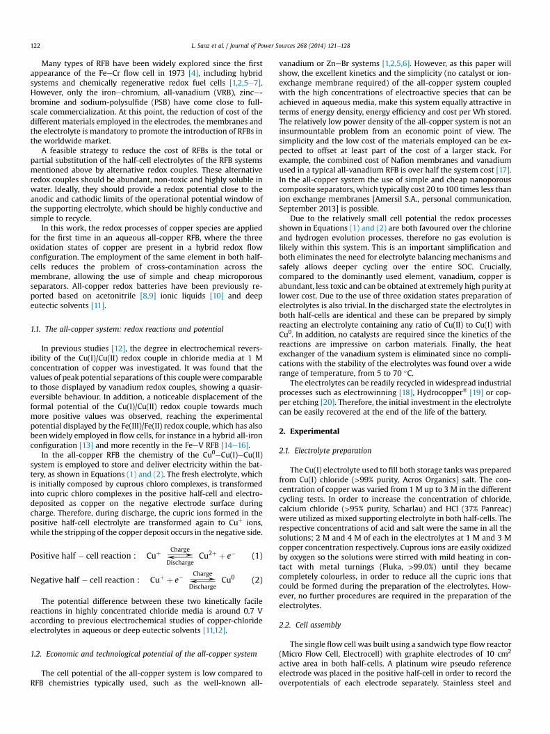
Fig. 1. Cyclic voltammetric measurements for the deposition and stripping of copper(A) and the Cu(I)/Cu(II) reaction in a 3 M Cu(I) solution (B) respectively. The scan ratewas varied between 0.2 and 0.02 V s�1. For the sake of clarity only every second scan isshown in Fig. 1A. The arrows indicate the direction of increasing scan rate.
L. Sanz et al. / Journal of Power Sources 268 (2014) 121e128 123
titanium foils were also tested as electrodes in the negative half-cell, to evaluate their performance as substrates for the electrode-position of copper. Nanoporous composite separators of PVC-Silica(Amersil S10) were employed. The thickness of the separator was0.6 mm and the volume of porosity around 70%, with a pore size of0.08 microns.
2.3. Pumps and storage
The flow ratewas controlled by peristaltic pumps (Masterflex L/SEasy Load) and the tubing was made of PVC (Nalgene, 3.6 mm innerdiameter),which is particularly suited for usewith concentratedHCl.
The hermetically sealed glass electrolyte storage tanks werethermostated using a water bath. Thermometers were insertedinside the tanks to monitor the temperature in the bulk electro-lytes. In addition, magnetic stirrers were placed in the tanks tomaintain a homogenous mixture of the species. The electrolyteswere gently purged with argon before being injected in the tanks.The diffusion of oxygen through the PVC tubing could not becompletely avoided during the experiments.
2.4. Cycling tests
Various charge and discharge cycling experiments were per-formed at constant current after the system had initially beencharged from 0 to 50% SOC. The temperature and the flow rateswere varied in order to determine the overpotentials of both thecharge and discharge processes over a wide range of current den-sities. The potential was limited up to 0.9 V on charge and down to0.3 V on discharge.
Charge and discharge experiments at constant current were alsocarried out to study the stability and the degradation of the processover more than 20 cycles. The flow rate was high enough to ensuregood convection of species within the cell compartments(35 mL min�1) while the volume of the electrolytes was 25 mL ineach tank. The current density was 20 mA cm�2 and the duration ofthe charge cycles was 1 h, thus the SOC was varied by 10% in eachcycle from 50 to 60%.
3. Results
3.1. Initial voltammetric studies
Fig. 1A and B shows the Cu(I)/Cu0 and Cu(II)/Cu(I) processesrespectively at a GC working electrode (5 mm glassy carbon, PineResearch Instrumentation AFE3T050 GC). These were measuredusing the same electrolyte (3 M CuCl, 4 M HCl/CaCl2) and temper-ature (60 �C) employed during RFB measurements and were per-formed sequentially with the same electrolyte and electrode. Thereference electrode was a copper wire. To simplify interpretationand make the results as accessible as possible, the electrode wasonly rotated between each measurement to refresh the solution infront of the electrode and was otherwise stationary.
3.1.1. Negative half-cell reactionAround 100 mV of overpotential appears to be required for
nucleation of copper deposition on GC. Once nucleation occurs, nodifference is apparent between the various scan rates used. A slightscan rate dependency during the stripping process can be observed,with a second process apparent at lower scan rates (labelled b inFig. 1A). This effect has been previously reported by several authors[21,22] and indicates that the stripping of copper in chloride con-taining solutions proceeds through two stages, an initial process toform an adsorbed CuCl deposit on the copper surface, followed byformation of a [CuCl2]� complex [23]. The limiting current density
that can be achieved at the negative electrode during discharge islikely related to either transport limitations for free chloride insolution or the kinetics of CuCl2� formation. These limitations can beexpected to become more pronounced at low temperatures andchloride concentrations [24].
The observed current densities during deposition are favour-able, considering that in an actual RFB the intended operatingcurrent is around 20 mA cm�2. When the charge passed duringdeposition and stripping is integrated the Coulombic efficiency isfound to be 85 ± 2%, this indicates parasitic losses. By contrast,when the potential is switched at �0.15 V the Coulombic efficiencyincreases to 94 ± 2%. This dependency of the Coulombic efficiencyon the switching potential can most likely be attributed to eitherhydrogen evolution at excessively negative overpotentials orincomplete stripping of the larger amount of copper deposited atmore negative switching potentials.
To further probe the deposition and stripping reactions, the RDEwas used to simulate conditions in the negative half-cell of the RFBduring operation, using a technique previously reported by Niki-foridis et al. [25]. By rotating the electrode (1000 RPM) a continuousflow of electrolyte passes over the electrode surface, as in an RFB.When a deposition and stripping current density of 20 mA cm�2 isapplied to an initially uncoated GC electrode a Coulombic efficiencyof 90 ± 3% is observed for the first ten cycles (presented inSupplementary data). After this, a drop in the Coulombic efficiencytakes place. At the same time the overpotentials required to chargeand discharge the cell increases and results in a drop in the voltageefficiency of the deposition and stripping reaction from 94.6 ± 0.9%
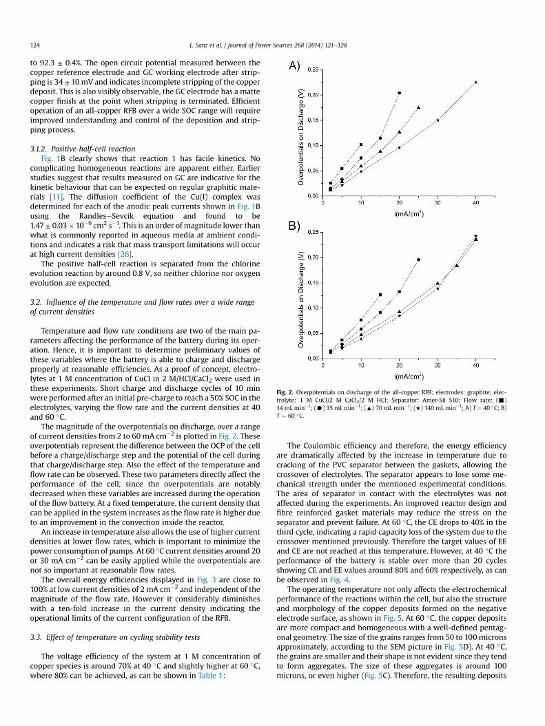
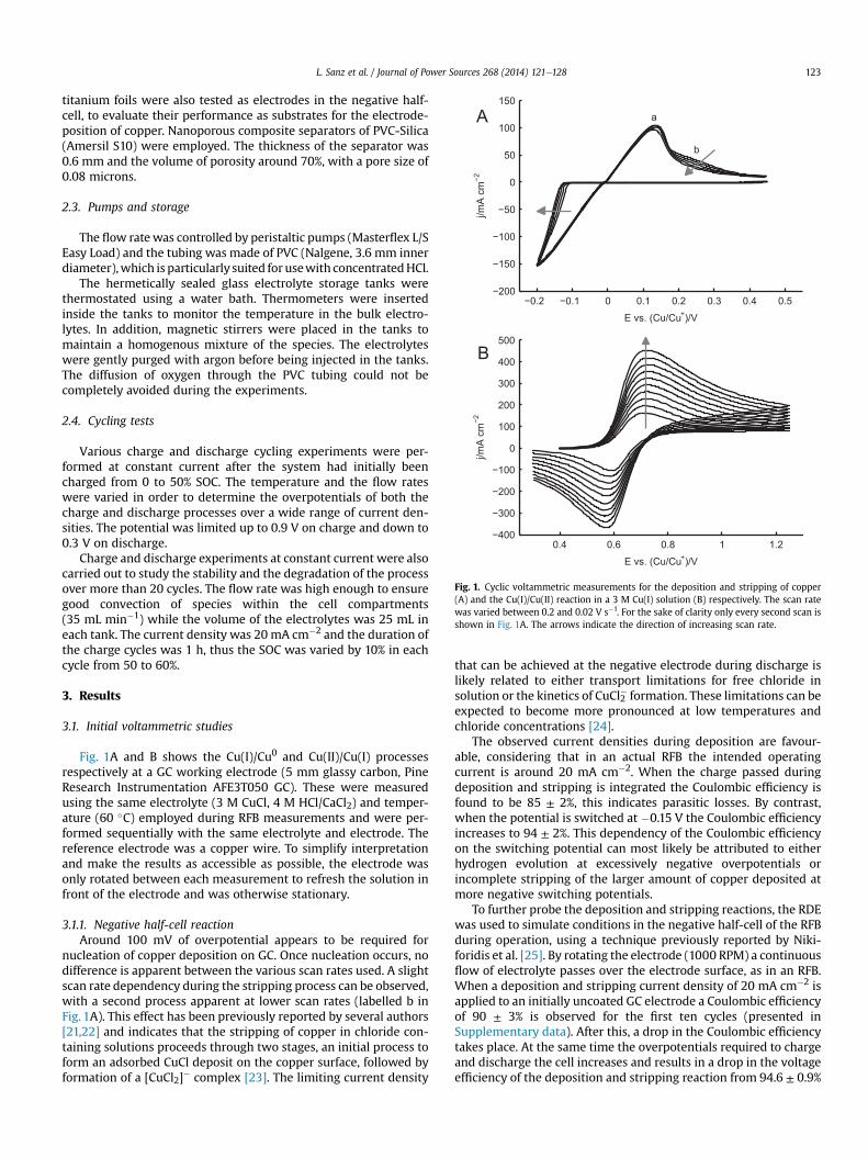
Fig. 2. Overpotentials on discharge of the all-copper RFB; electrodes: graphite; elec-trolyte: 1 M CuCl/2 M CaCl2/2 M HCl; Separator: Amer-Sil S10; Flow rate: (-)14 mL min�1; (C) 35 mL min�1; (:) 70 mL min�1; (+) 140 mL min�1; A) T ¼ 40 �C; B)T ¼ 60 �C.
L. Sanz et al. / Journal of Power Sources 268 (2014) 121e128124
to 92.3 ± 0.4%. The open circuit potential measured between thecopper reference electrode and GC working electrode after strip-ping is 34 ± 10mV and indicates incomplete stripping of the copperdeposit. This is also visibly observable, the GC electrode has a mattecopper finish at the point when stripping is terminated. Efficientoperation of an all-copper RFB over a wide SOC range will requireimproved understanding and control of the deposition and strip-ping process.
3.1.2. Positive half-cell reactionFig. 1B clearly shows that reaction 1 has facile kinetics. No
complicating homogeneous reactions are apparent either. Earlierstudies suggest that results measured on GC are indicative for thekinetic behaviour that can be expected on regular graphitic mate-rials [11]. The diffusion coefficient of the Cu(I) complex wasdetermined for each of the anodic peak currents shown in Fig. 1Busing the RandleseSevcik equation and found to be1.47 ± 0.03�10�6 cm2 s�1. This is an order of magnitude lower thanwhat is commonly reported in aqueous media at ambient condi-tions and indicates a risk that mass transport limitations will occurat high current densities [26].
The positive half-cell reaction is separated from the chlorineevolution reaction by around 0.8 V, so neither chlorine nor oxygenevolution are expected.
3.2. Influence of the temperature and flow rates over a wide rangeof current densities
Temperature and flow rate conditions are two of the main pa-rameters affecting the performance of the battery during its oper-ation. Hence, it is important to determine preliminary values ofthese variables where the battery is able to charge and dischargeproperly at reasonable efficiencies. As a proof of concept, electro-lytes at 1 M concentration of CuCl in 2 M/HCl/CaCl2 were used inthese experiments. Short charge and discharge cycles of 10 minwere performed after an initial pre-charge to reach a 50% SOC in theelectrolytes, varying the flow rate and the current densities at 40and 60 �C.
The magnitude of the overpotentials on discharge, over a rangeof current densities from 2 to 60 mA cm�2 is plotted in Fig. 2. Theseoverpotentials represent the difference between the OCP of the cellbefore a charge/discharge step and the potential of the cell duringthat charge/discharge step. Also the effect of the temperature andflow rate can be observed. These two parameters directly affect theperformance of the cell, since the overpotentials are notablydecreased when these variables are increased during the operationof the flow battery. At a fixed temperature, the current density thatcan be applied in the system increases as the flow rate is higher dueto an improvement in the convection inside the reactor.
An increase in temperature also allows the use of higher currentdensities at lower flow rates, which is important to minimize thepower consumption of pumps. At 60 �C current densities around 20or 30 mA cm�2 can be easily applied while the overpotentials arenot so important at reasonable flow rates.
The overall energy efficiencies displayed in Fig. 3 are close to100% at low current densities of 2 mA cm�2 and independent of themagnitude of the flow rate. However it considerably diminisheswith a ten-fold increase in the current density indicating theoperational limits of the current configuration of the RFB.
3.3. Effect of temperature on cycling stability tests
The voltage efficiency of the system at 1 M concentration ofcopper species is around 70% at 40 �C and slightly higher at 60 �C,where 80% can be achieved, as can be shown in Table 1:
The Coulombic efficiency and therefore, the energy efficiencyare dramatically affected by the increase in temperature due tocracking of the PVC separator between the gaskets, allowing thecrossover of electrolytes. The separator appears to lose some me-chanical strength under the mentioned experimental conditions.The area of separator in contact with the electrolytes was notaffected during the experiments. An improved reactor design andfibre reinforced gasket materials may reduce the stress on theseparator and prevent failure. At 60 �C, the CE drops to 40% in thethird cycle, indicating a rapid capacity loss of the system due to thecrossover mentioned previously. Therefore the target values of EEand CE are not reached at this temperature. However, at 40 �C theperformance of the battery is stable over more than 20 cyclesshowing CE and EE values around 80% and 60% respectively, as canbe observed in Fig. 4.
The operating temperature not only affects the electrochemicalperformance of the reactions within the cell, but also the structureand morphology of the copper deposits formed on the negativeelectrode surface, as shown in Fig. 5. At 60 �C, the copper depositsare more compact and homogeneous with a well-defined pentag-onal geometry. The size of the grains ranges from 50 to 100micronsapproximately, according to the SEM picture in Fig. 5D). At 40 �C,the grains are smaller and their shape is not evident since they tendto form aggregates. The size of these aggregates is around 100microns, or even higher (Fig. 5C). Therefore, the resulting deposits
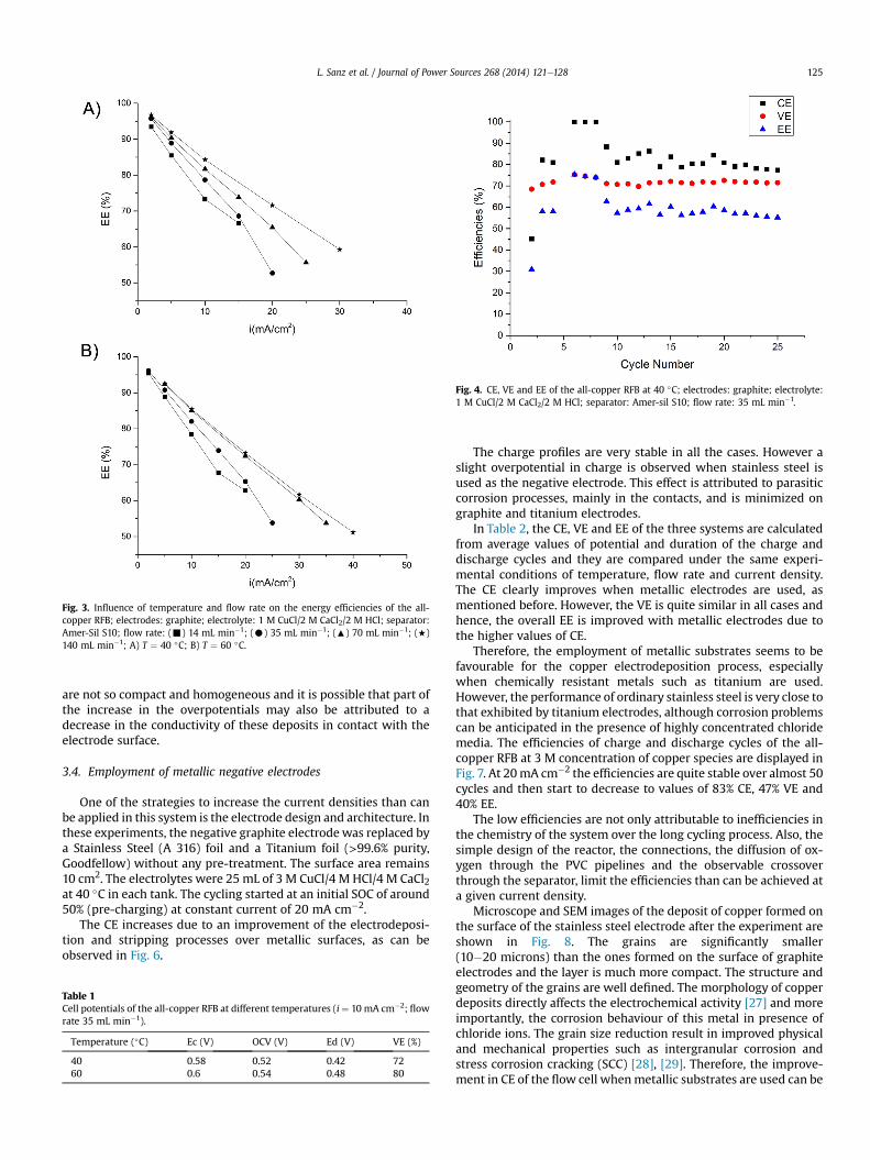
Fig. 4. CE, VE and EE of the all-copper RFB at 40 �C; electrodes: graphite; electrolyte:1 M CuCl/2 M CaCl2/2 M HCl; separator: Amer-sil S10; flow rate: 35 mL min�1.
Fig. 3. Influence of temperature and flow rate on the energy efficiencies of the all-copper RFB; electrodes: graphite; electrolyte: 1 M CuCl/2 M CaCl2/2 M HCl; separator:Amer-Sil S10; flow rate: (-) 14 mL min�1; (C) 35 mL min�1; (:) 70 mL min�1; (+)140 mL min�1; A) T ¼ 40 �C; B) T ¼ 60 �C.
L. Sanz et al. / Journal of Power Sources 268 (2014) 121e128 125
are not so compact and homogeneous and it is possible that part ofthe increase in the overpotentials may also be attributed to adecrease in the conductivity of these deposits in contact with theelectrode surface.
3.4. Employment of metallic negative electrodes
One of the strategies to increase the current densities than canbe applied in this system is the electrode design and architecture. Inthese experiments, the negative graphite electrodewas replaced bya Stainless Steel (A 316) foil and a Titanium foil (>99.6% purity,Goodfellow) without any pre-treatment. The surface area remains10 cm2. The electrolytes were 25 mL of 3 M CuCl/4 M HCl/4 M CaCl2at 40 �C in each tank. The cycling started at an initial SOC of around50% (pre-charging) at constant current of 20 mA cm�2.
The CE increases due to an improvement of the electrodeposi-tion and stripping processes over metallic surfaces, as can beobserved in Fig. 6.
Table 1Cell potentials of the all-copper RFB at different temperatures (i¼ 10 mA cm�2; flowrate 35 mL min�1).
Temperature (�C) Ec (V) OCV (V) Ed (V) VE (%)
40 0.58 0.52 0.42 7260 0.6 0.54 0.48 80
The charge profiles are very stable in all the cases. However aslight overpotential in charge is observed when stainless steel isused as the negative electrode. This effect is attributed to parasiticcorrosion processes, mainly in the contacts, and is minimized ongraphite and titanium electrodes.
In Table 2, the CE, VE and EE of the three systems are calculatedfrom average values of potential and duration of the charge anddischarge cycles and they are compared under the same experi-mental conditions of temperature, flow rate and current density.The CE clearly improves when metallic electrodes are used, asmentioned before. However, the VE is quite similar in all cases andhence, the overall EE is improved with metallic electrodes due tothe higher values of CE.
Therefore, the employment of metallic substrates seems to befavourable for the copper electrodeposition process, especiallywhen chemically resistant metals such as titanium are used.However, the performance of ordinary stainless steel is very close tothat exhibited by titanium electrodes, although corrosion problemscan be anticipated in the presence of highly concentrated chloridemedia. The efficiencies of charge and discharge cycles of the all-copper RFB at 3 M concentration of copper species are displayed inFig. 7. At 20mA cm�2 the efficiencies are quite stable over almost 50cycles and then start to decrease to values of 83% CE, 47% VE and40% EE.
The low efficiencies are not only attributable to inefficiencies inthe chemistry of the system over the long cycling process. Also, thesimple design of the reactor, the connections, the diffusion of ox-ygen through the PVC pipelines and the observable crossoverthrough the separator, limit the efficiencies than can be achieved ata given current density.
Microscope and SEM images of the deposit of copper formed onthe surface of the stainless steel electrode after the experiment areshown in Fig. 8. The grains are significantly smaller(10�20 microns) than the ones formed on the surface of graphiteelectrodes and the layer is much more compact. The structure andgeometry of the grains are well defined. The morphology of copperdeposits directly affects the electrochemical activity [27] and moreimportantly, the corrosion behaviour of this metal in presence ofchloride ions. The grain size reduction result in improved physicaland mechanical properties such as intergranular corrosion andstress corrosion cracking (SCC) [28], [29]. Therefore, the improve-ment in CE of the flow cell whenmetallic substrates are used can be
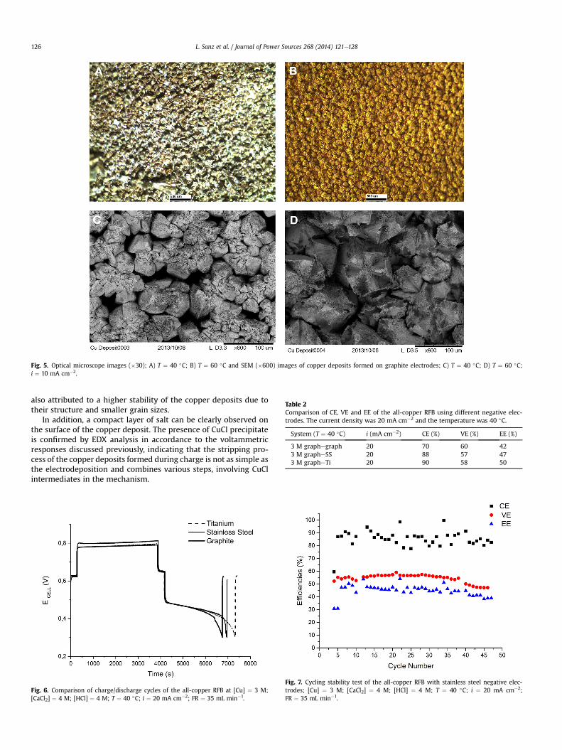
Fig. 5. Optical microscope images (�30); A) T ¼ 40 �C; B) T ¼ 60 �C and SEM (�600) images of copper deposits formed on graphite electrodes; C) T ¼ 40 �C; D) T ¼ 60 �C;i ¼ 10 mA cm�2.
Table 2Comparison of CE, VE and EE of the all-copper RFB using different negative elec-trodes. The current density was 20 mA cm�2 and the temperature was 40 �C.
System (T ¼ 40 �C) i (mA cm�2) CE (%) VE (%) EE (%)
3 M graphegraph 20 70 60 423 M grapheSS 20 88 57 473 M grapheTi 20 90 58 50
L. Sanz et al. / Journal of Power Sources 268 (2014) 121e128126
also attributed to a higher stability of the copper deposits due totheir structure and smaller grain sizes.
In addition, a compact layer of salt can be clearly observed onthe surface of the copper deposit. The presence of CuCl precipitateis confirmed by EDX analysis in accordance to the voltammetricresponses discussed previously, indicating that the stripping pro-cess of the copper deposits formed during charge is not as simple asthe electrodeposition and combines various steps, involving CuClintermediates in the mechanism.
Fig. 6. Comparison of charge/discharge cycles of the all-copper RFB at [Cu] ¼ 3 M;[CaCl2] ¼ 4 M; [HCl] ¼ 4 M; T ¼ 40 �C; i ¼ 20 mA cm�2; FR ¼ 35 mL min�1.
Fig. 7. Cycling stability test of the all-copper RFB with stainless steel negative elec-trodes; [Cu] ¼ 3 M; [CaCl2] ¼ 4 M; [HCl] ¼ 4 M; T ¼ 40 �C; i ¼ 20 mA cm�2;FR ¼ 35 mL min�1.
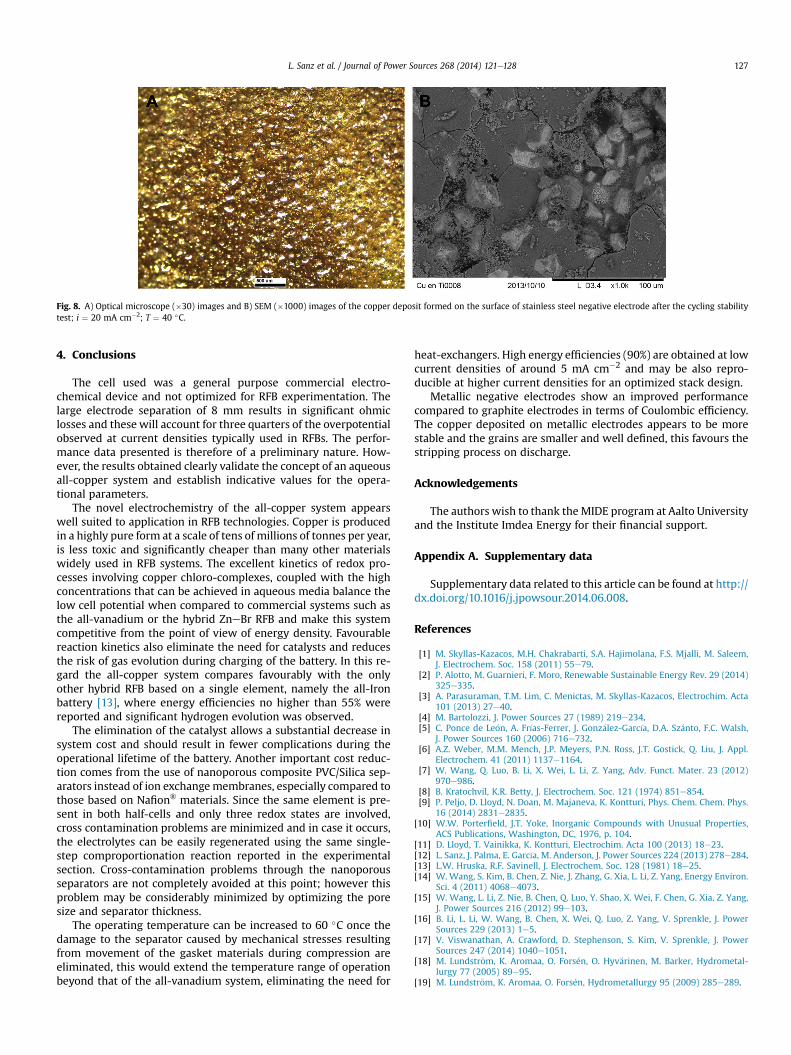
Fig. 8. A) Optical microscope (�30) images and B) SEM (�1000) images of the copper deposit formed on the surface of stainless steel negative electrode after the cycling stabilitytest; i ¼ 20 mA cm�2; T ¼ 40 �C.
L. Sanz et al. / Journal of Power Sources 268 (2014) 121e128 127
4. Conclusions
The cell used was a general purpose commercial electro-chemical device and not optimized for RFB experimentation. Thelarge electrode separation of 8 mm results in significant ohmiclosses and these will account for three quarters of the overpotentialobserved at current densities typically used in RFBs. The perfor-mance data presented is therefore of a preliminary nature. How-ever, the results obtained clearly validate the concept of an aqueousall-copper system and establish indicative values for the opera-tional parameters.
The novel electrochemistry of the all-copper system appearswell suited to application in RFB technologies. Copper is producedin a highly pure form at a scale of tens of millions of tonnes per year,is less toxic and significantly cheaper than many other materialswidely used in RFB systems. The excellent kinetics of redox pro-cesses involving copper chloro-complexes, coupled with the highconcentrations that can be achieved in aqueous media balance thelow cell potential when compared to commercial systems such asthe all-vanadium or the hybrid ZneBr RFB and make this systemcompetitive from the point of view of energy density. Favourablereaction kinetics also eliminate the need for catalysts and reducesthe risk of gas evolution during charging of the battery. In this re-gard the all-copper system compares favourably with the onlyother hybrid RFB based on a single element, namely the all-Ironbattery [13], where energy efficiencies no higher than 55% werereported and significant hydrogen evolution was observed.
The elimination of the catalyst allows a substantial decrease insystem cost and should result in fewer complications during theoperational lifetime of the battery. Another important cost reduc-tion comes from the use of nanoporous composite PVC/Silica sep-arators instead of ion exchangemembranes, especially compared tothose based on Nafion® materials. Since the same element is pre-sent in both half-cells and only three redox states are involved,cross contamination problems are minimized and in case it occurs,the electrolytes can be easily regenerated using the same single-step comproportionation reaction reported in the experimentalsection. Cross-contamination problems through the nanoporousseparators are not completely avoided at this point; however thisproblem may be considerably minimized by optimizing the poresize and separator thickness.
The operating temperature can be increased to 60 �C once thedamage to the separator caused by mechanical stresses resultingfrom movement of the gasket materials during compression areeliminated, this would extend the temperature range of operationbeyond that of the all-vanadium system, eliminating the need for
heat-exchangers. High energy efficiencies (90%) are obtained at lowcurrent densities of around 5 mA cm�2 and may be also repro-ducible at higher current densities for an optimized stack design.
Metallic negative electrodes show an improved performancecompared to graphite electrodes in terms of Coulombic efficiency.The copper deposited on metallic electrodes appears to be morestable and the grains are smaller and well defined, this favours thestripping process on discharge.
Acknowledgements
The authors wish to thank theMIDE program at Aalto Universityand the Institute Imdea Energy for their financial support.
Appendix A. Supplementary data
Supplementary data related to this article can be found at http://dx.doi.org/10.1016/j.jpowsour.2014.06.008.
References
[1] M. Skyllas-Kazacos, M.H. Chakrabarti, S.A. Hajimolana, F.S. Mjalli, M. Saleem,J. Electrochem. Soc. 158 (2011) 55e79.
[2] P. Alotto, M. Guarnieri, F. Moro, Renewable Sustainable Energy Rev. 29 (2014)325e335.
[3] A. Parasuraman, T.M. Lim, C. Menictas, M. Skyllas-Kazacos, Electrochim. Acta101 (2013) 27e40.
[4] M. Bartolozzi, J. Power Sources 27 (1989) 219e234.[5] C. Ponce de Le�on, A. Frías-Ferrer, J. Gonz�alez-García, D.A. Sz�anto, F.C. Walsh,
J. Power Sources 160 (2006) 716e732.[6] A.Z. Weber, M.M. Mench, J.P. Meyers, P.N. Ross, J.T. Gostick, Q. Liu, J. Appl.
Electrochem. 41 (2011) 1137e1164.[7] W. Wang, Q. Luo, B. Li, X. Wei, L. Li, Z. Yang, Adv. Funct. Mater. 23 (2012)
970e986.[8] B. Kratochvil, K.R. Betty, J. Electrochem. Soc. 121 (1974) 851e854.[9] P. Peljo, D. Lloyd, N. Doan, M. Majaneva, K. Kontturi, Phys. Chem. Chem. Phys.
16 (2014) 2831e2835.[10] W.W. Porterfield, J.T. Yoke, Inorganic Compounds with Unusual Properties,
ACS Publications, Washington, DC, 1976, p. 104.[11] D. Lloyd, T. Vainikka, K. Kontturi, Electrochim. Acta 100 (2013) 18e23.[12] L. Sanz, J. Palma, E. García, M. Anderson, J. Power Sources 224 (2013) 278e284.[13] L.W. Hruska, R.F. Savinell, J. Electrochem. Soc. 128 (1981) 18e25.[14] W. Wang, S. Kim, B. Chen, Z. Nie, J. Zhang, G. Xia, L. Li, Z. Yang, Energy Environ.
Sci. 4 (2011) 4068e4073.[15] W. Wang, L. Li, Z. Nie, B. Chen, Q. Luo, Y. Shao, X. Wei, F. Chen, G. Xia, Z. Yang,
J. Power Sources 216 (2012) 99e103.[16] B. Li, L. Li, W. Wang, B. Chen, X. Wei, Q. Luo, Z. Yang, V. Sprenkle, J. Power
Sources 229 (2013) 1e5.[17] V. Viswanathan, A. Crawford, D. Stephenson, S. Kim, V. Sprenkle, J. Power
Sources 247 (2014) 1040e1051.[18] M. Lundstr€om, K. Aromaa, O. Fors�en, O. Hyv€arinen, M. Barker, Hydrometal-
lurgy 77 (2005) 89e95.[19] M. Lundstr€om, K. Aromaa, O. Fors�en, Hydrometallurgy 95 (2009) 285e289.

L. Sanz et al. / Journal of Power Sources 268 (2014) 121e128128
[20] O. Cakir, J. Mater. Process. Technol. 175 (2006) 63e68.[21] D. Starosvetsky, O. Khaselev, M. Auinat, Y. Ein-Eli, Electrochim. Acta 51 (2006)
5660e5668.[22] S. Kologo, M. Eyraud, L. Bonou, F. Vacandio, Y. Massiani, Electrochim. Acta 52
(2007) 3105e3113.[23] K. Shi, K. Hu, S. Wang, C. Lau, K. Shiu, Electrochim. Acta 52 (2007) 5907e5913.[24] H. Zhao, J. Chang, A. Boika, A.J. Bard, Anal. Chem. 85 (2013) 7696e7703.[25] G. Nikiforidis, L. Berlouis, D. Hall, D. Hodgson, J. Power Sources 206 (2012)
497e503.
[26] P. Kiekens, R.M.H. Verbeeck, E. Temmerman, Microchim. Acta 2 (1981) 29e36.[27] E. Martinez-Lombardia, Y. Gonzalez-Garcia, L. Lapeire, I. De Graeve,
K. Verbeken, L. Kestens, J.M.C. Mol, H. Terryn, Electrochim. Acta 116 (2014)89e96.
[28] S.H. Kim, K.T. Aust, F. Gonzalez, G. Palumbo, Plat. Surf. Finish. 91 (2004)68e70.
[29] W. Deng, P. Lin, Q. Li, G. Mo, Corros. Sci. 74 (2013) 44e49.