Embed Size (px)
Citation preview

Cambridge IGCSE™
DC (KN) 206032© UCLES 2020 [Turn over
This document has 20 pages. Blank pages are indicated.
DESIGN & TECHNOLOGY 0445/43
Paper 4 Systems & Control October/November 2020
1 hour
You must answer on the question paper.
No additional materials are needed.
INSTRUCTIONS ● Section A: answer all questions. ● Section B: answer one question. ● Use a black or dark blue pen. You may use an HB pencil for any diagrams or graphs. ● Write your name, centre number and candidate number in the boxes at the top of the page. ● Answer in the space provided. ● Do not use an erasable pen or correction fluid. ● Do not write on any bar codes. ● You may use a calculator.
INFORMATION ● The total mark for this paper is 50. ● The number of marks for each question or part question is shown in brackets [ ]. ● All dimensions are in millimetres.
*3441783522*
2
0445/43/O/N/20© UCLES 2020
Section A
Answer all questions in this section.
1 Circle two infinite energy sources from the list below.
coal wind oil solar natural gas [2]
2 (a) State one advantage of using CAD/CAM in batch production.
...................................................................................................................................................
.............................................................................................................................................. [1]
(b) Name one manufacturing machine that can be controlled by a computer.
.............................................................................................................................................. [1]
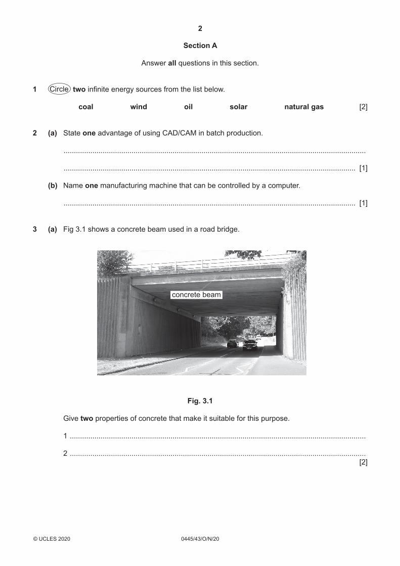
3 (a) Fig 3.1 shows a concrete beam used in a road bridge.
concrete beam
Fig. 3.1
Give two properties of concrete that make it suitable for this purpose.
1 ................................................................................................................................................
2 ................................................................................................................................................ [2]
3
0445/43/O/N/20© UCLES 2020 [Turn over
(b) (i) Use sketches and notes to show how steel can be used to reinforce a concrete beam.
[2]
(ii) Name the main force resisted by steel in a concrete beam.
..................................................................................................................................... [1]
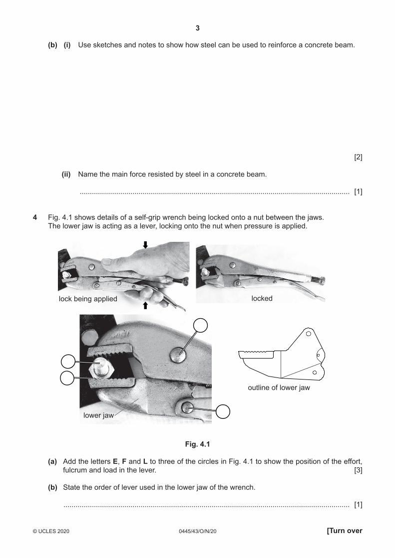
4 Fig. 4.1 shows details of a self-grip wrench being locked onto a nut between the jaws. The lower jaw is acting as a lever, locking onto the nut when pressure is applied.
outline of lower jaw
lockedlock being applied
lower jaw
Fig. 4.1
(a) Add the letters E, F and L to three of the circles in Fig. 4.1 to show the position of the effort, fulcrum and load in the lever. [3]
(b) State the order of lever used in the lower jaw of the wrench.
............................................................................................................................................. [1]
4
0445/43/O/N/20© UCLES 2020
5 State the type of motion which occurs in the following examples.
Clock pendulum ...............................................................................................................................
Cutting with a hacksaw .................................................................................................................... [2]
6 Give two reasons for using spur gears to transmit motion in a mechanism.
1 .......................................................................................................................................................
..........................................................................................................................................................
2 .......................................................................................................................................................
.......................................................................................................................................................... [2]
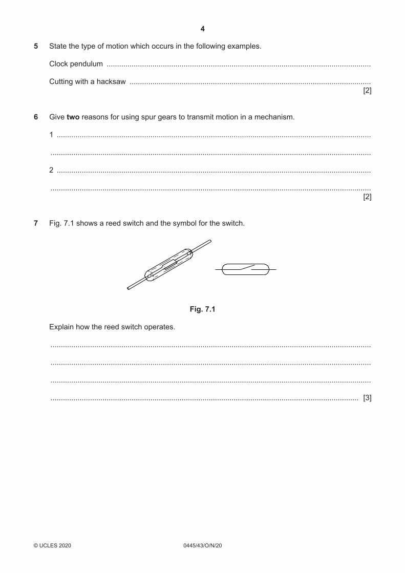
7 Fig. 7.1 shows a reed switch and the symbol for the switch.
Fig. 7.1
Explain how the reed switch operates.
..........................................................................................................................................................
..........................................................................................................................................................
..........................................................................................................................................................
.................................................................................................................................................... [3]
5
0445/43/O/N/20© UCLES 2020 [Turn over
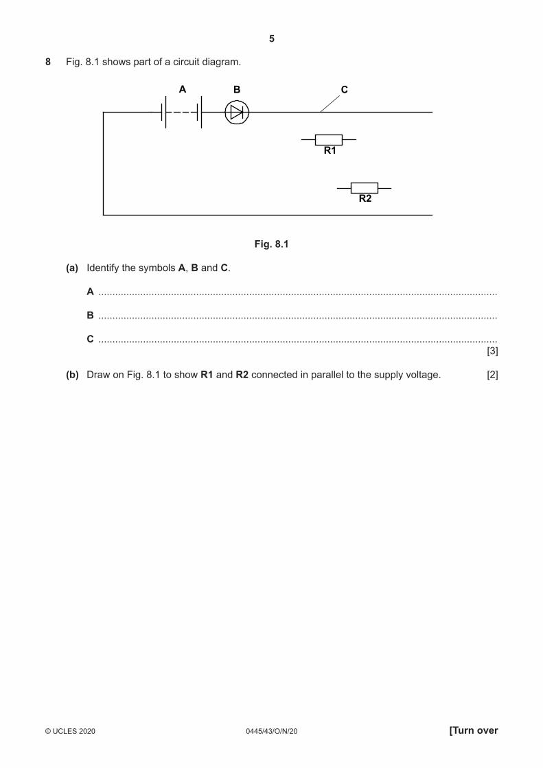
8 Fig. 8.1 shows part of a circuit diagram.
A B C
R2
R1
Fig. 8.1
(a) Identify the symbols A, B and C.
A ...............................................................................................................................................
B ...............................................................................................................................................
C ............................................................................................................................................... [3]
(b) Draw on Fig. 8.1 to show R1 and R2 connected in parallel to the supply voltage. [2]
6
0445/43/O/N/20© UCLES 2020
Section B
Answer one question from this section.
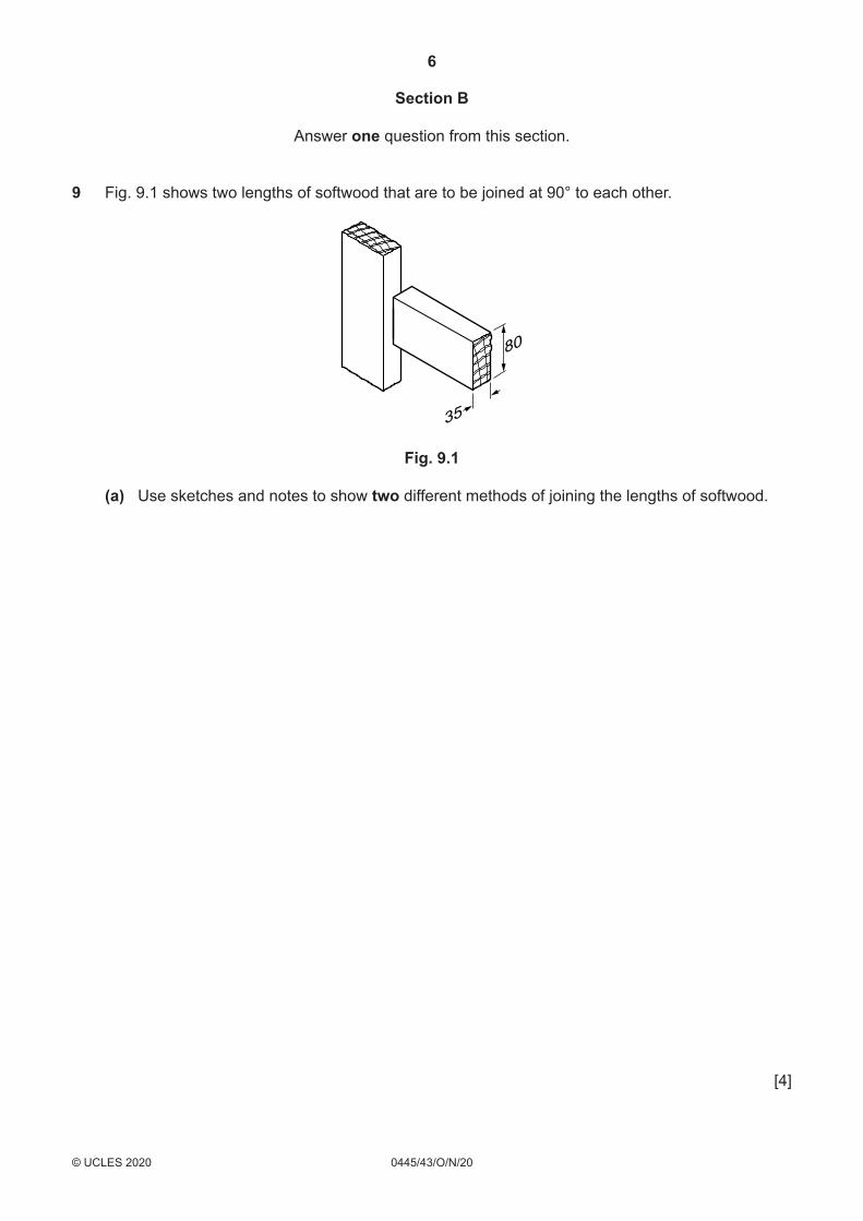
9 Fig. 9.1 shows two lengths of softwood that are to be joined at 90° to each other.
80
35
Fig. 9.1
(a) Use sketches and notes to show two different methods of joining the lengths of softwood.
[4]
7
0445/43/O/N/20© UCLES 2020 [Turn over
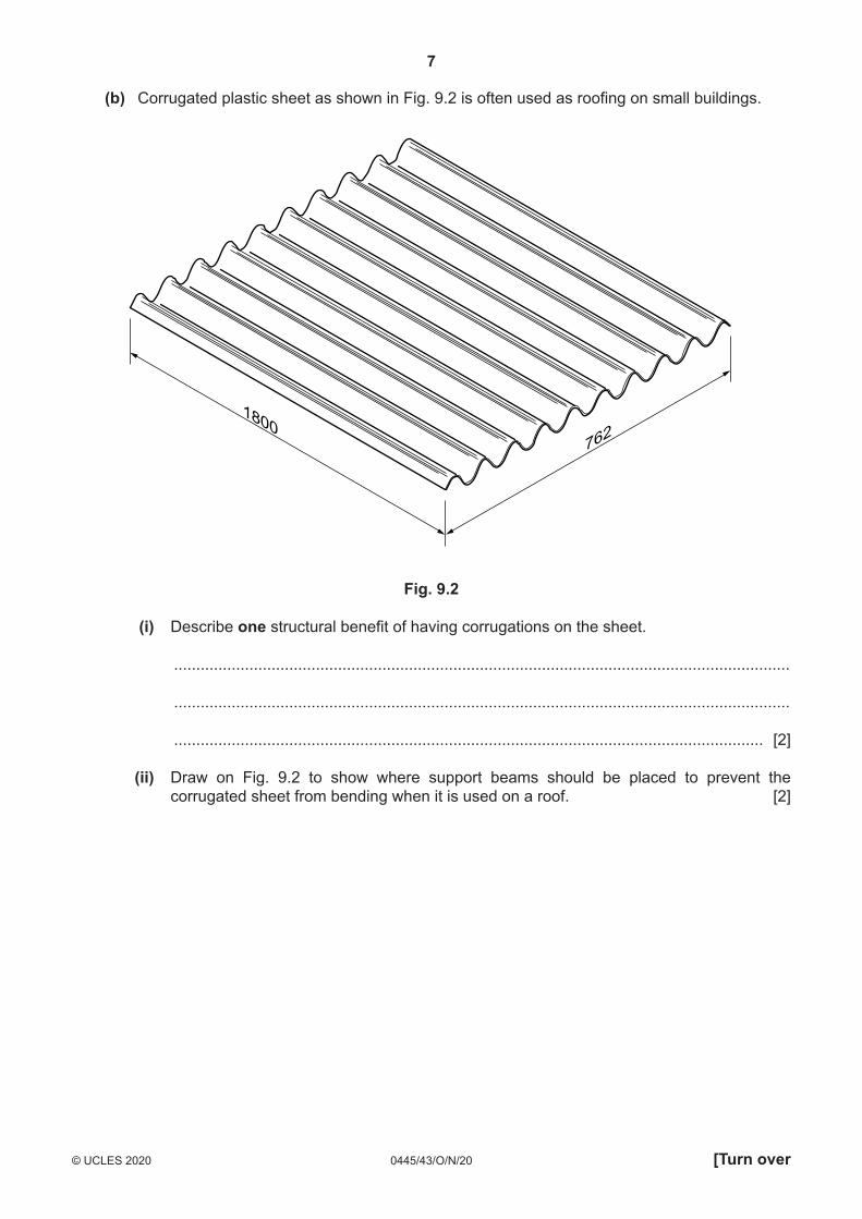
(b) Corrugated plastic sheet as shown in Fig. 9.2 is often used as roofing on small buildings.
1800762
Fig. 9.2
(i) Describe one structural benefit of having corrugations on the sheet.
...........................................................................................................................................
...........................................................................................................................................
..................................................................................................................................... [2]
(ii) Draw on Fig. 9.2 to show where support beams should be placed to prevent the corrugated sheet from bending when it is used on a roof. [2]
8
0445/43/O/N/20© UCLES 2020
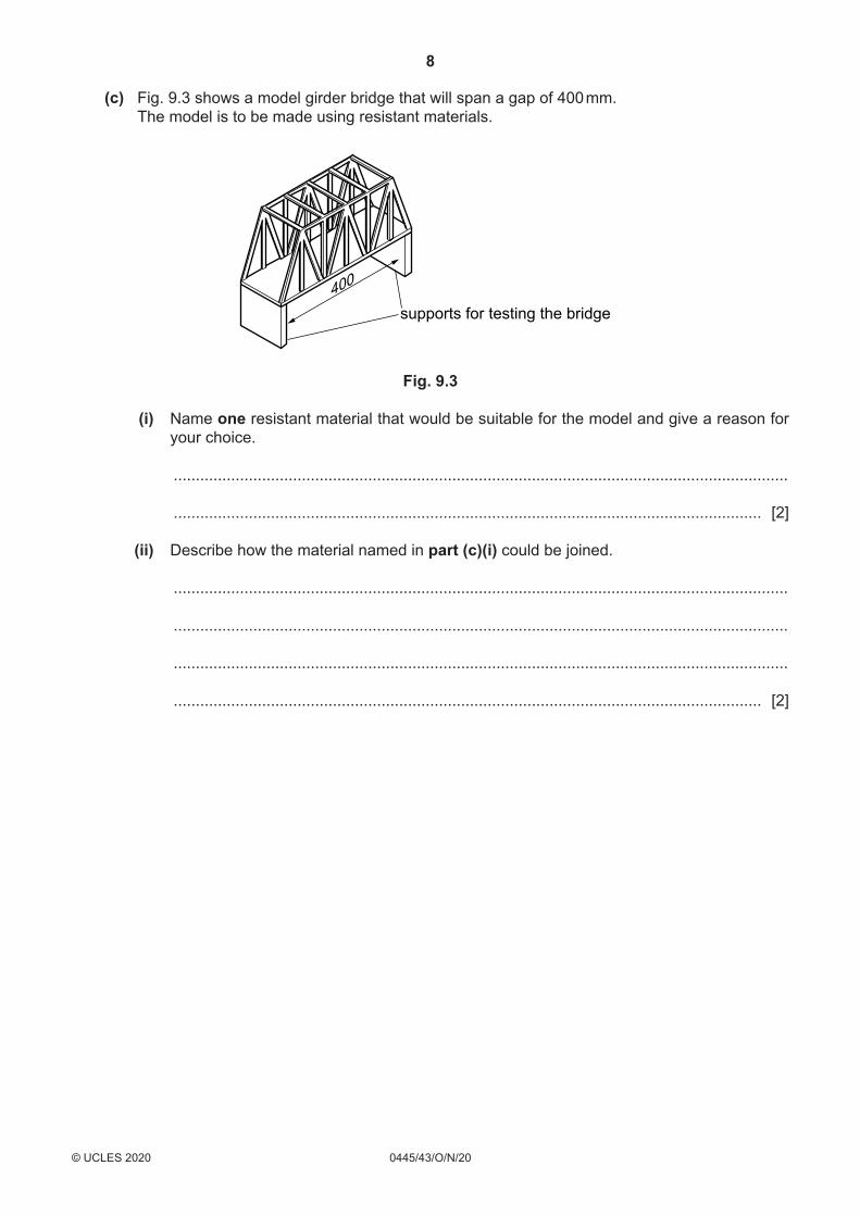
(c) Fig. 9.3 shows a model girder bridge that will span a gap of 400 mm. The model is to be made using resistant materials.
supports for testing the bridge400
Fig. 9.3
(i) Name one resistant material that would be suitable for the model and give a reason for your choice.
...........................................................................................................................................
..................................................................................................................................... [2]
(ii) Describe how the material named in part (c)(i) could be joined.
...........................................................................................................................................
...........................................................................................................................................
...........................................................................................................................................
..................................................................................................................................... [2]

9
0445/43/O/N/20© UCLES 2020 [Turn over
(iii) Use sketches and notes to show how the model could be tested and evaluated.
[3]
10
0445/43/O/N/20© UCLES 2020
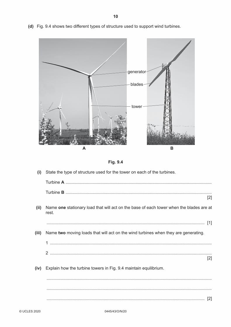
(d) Fig. 9.4 shows two different types of structure used to support wind turbines.
generator
blades
tower
A B
Fig. 9.4
(i) State the type of structure used for the tower on each of the turbines.
Turbine A ...........................................................................................................................
Turbine B ........................................................................................................................... [2]
(ii) Name one stationary load that will act on the base of each tower when the blades are at rest.
..................................................................................................................................... [1] (iii) Name two moving loads that will act on the wind turbines when they are generating.
1 ........................................................................................................................................
2 ........................................................................................................................................ [2]
(iv) Explain how the turbine towers in Fig. 9.4 maintain equilibrium.
...........................................................................................................................................
...........................................................................................................................................
..................................................................................................................................... [2]

11
0445/43/O/N/20© UCLES 2020 [Turn over
(e) A tie bar in a roof truss is made from a piece of steel rod Ø12 × 1.5 m long. When a load of 15 kN is applied the tie bar extends by 0.35 mm. Calculate the strain in the tie bar.
Use the formula: Strain = change in length
original length
...................................................................................................................................................
...................................................................................................................................................
...................................................................................................................................................
...................................................................................................................................................
Strain = ......................................................... [3]
12
0445/43/O/N/20© UCLES 2020
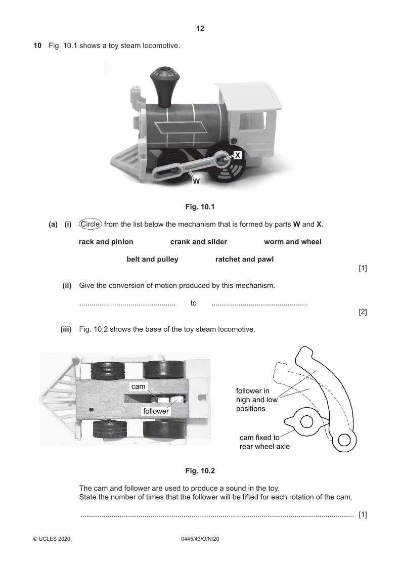
10 Fig. 10.1 shows a toy steam locomotive.
W
X
Fig. 10.1
(a) (i) Circle from the list below the mechanism that is formed by parts W and X.
rack and pinion crank and slider worm and wheel
belt and pulley ratchet and pawl [1]
(ii) Give the conversion of motion produced by this mechanism.
............................................... to ............................................... [2]
(iii) Fig. 10.2 shows the base of the toy steam locomotive.
follower inhigh and lowpositions
cam
follower
cam fixed torear wheel axle
Fig. 10.2
The cam and follower are used to produce a sound in the toy. State the number of times that the follower will be lifted for each rotation of the cam.
..................................................................................................................................... [1]
13
0445/43/O/N/20© UCLES 2020 [Turn over
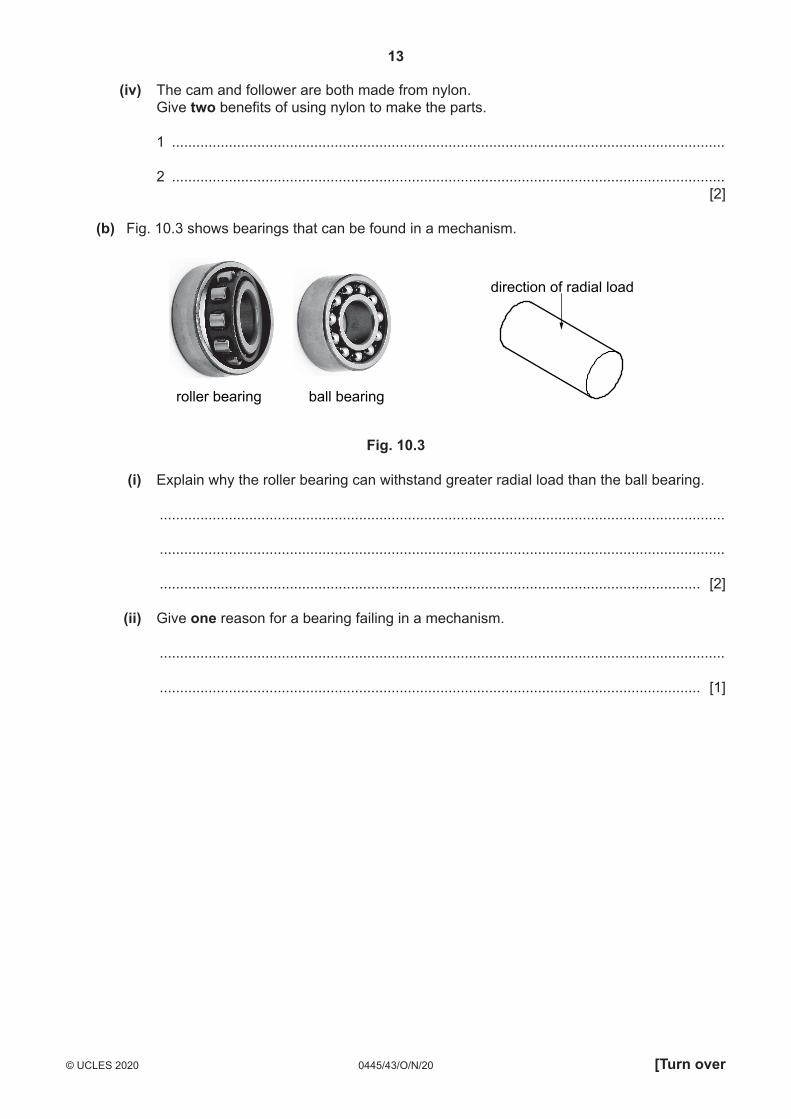
(iv) The cam and follower are both made from nylon. Give two benefits of using nylon to make the parts.
1 ........................................................................................................................................
2 ........................................................................................................................................ [2]
(b) Fig. 10.3 shows bearings that can be found in a mechanism.
direction of radial load
roller bearing ball bearing
Fig. 10.3
(i) Explain why the roller bearing can withstand greater radial load than the ball bearing.
...........................................................................................................................................
...........................................................................................................................................
..................................................................................................................................... [2]
(ii) Give one reason for a bearing failing in a mechanism.
...........................................................................................................................................
..................................................................................................................................... [1]
14
0445/43/O/N/20© UCLES 2020
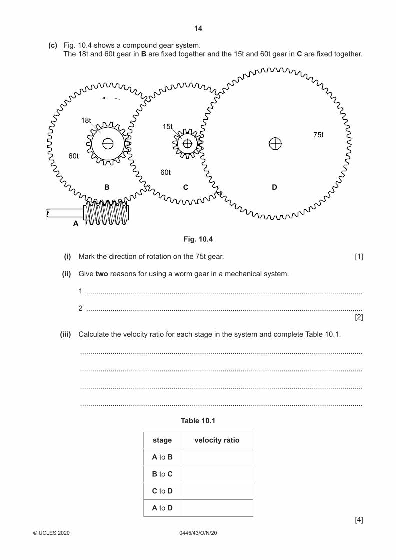
(c) Fig. 10.4 shows a compound gear system. The 18t and 60t gear in B are fixed together and the 15t and 60t gear in C are fixed together.
15t18t
60t
60t
75t
A
B C D
Fig. 10.4
(i) Mark the direction of rotation on the 75t gear. [1]
(ii) Give two reasons for using a worm gear in a mechanical system.
1 ........................................................................................................................................
2 ........................................................................................................................................ [2]
(iii) Calculate the velocity ratio for each stage in the system and complete Table 10.1.
...........................................................................................................................................
...........................................................................................................................................
...........................................................................................................................................
...........................................................................................................................................
Table 10.1
stage velocity ratio
A to B
B to C
C to D
A to D [4]

15
0445/43/O/N/20© UCLES 2020 [Turn over
(d) (i) Compare the following methods of transmitting motion. Give one advantage and one disadvantage for each method.
Chain drive
Advantage .........................................................................................................................
Disadvantage ....................................................................................................................
Pulley and round belt
Advantage .........................................................................................................................
Disadvantage ....................................................................................................................
Pulley and toothed belt
Advantage .........................................................................................................................
Disadvantage .................................................................................................................... [6]
(ii) Use sketches and notes to show one method of tensioning a drive belt.
[3]
16
0445/43/O/N/20© UCLES 2020
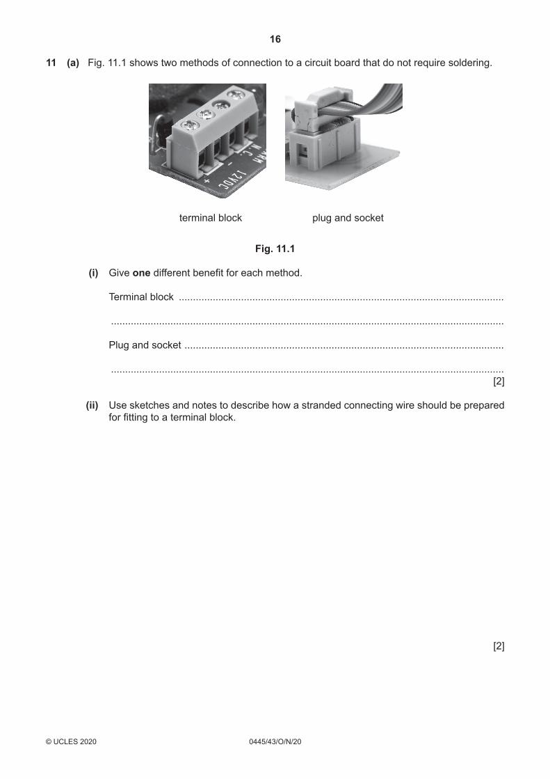
11 (a) Fig. 11.1 shows two methods of connection to a circuit board that do not require soldering.
terminal block plug and socket
Fig. 11.1
(i) Give one different benefit for each method.
Terminal block ...................................................................................................................
...........................................................................................................................................
Plug and socket .................................................................................................................
........................................................................................................................................... [2]
(ii) Use sketches and notes to describe how a stranded connecting wire should be prepared for fitting to a terminal block.
[2]

17
0445/43/O/N/20© UCLES 2020 [Turn over
(b) Fig. 11.2 shows part of a resistor colour code chart showing the values for the tolerance band.
Colour Tolerance
Brown 1%
Red 2%
Blue 0.25%
Gold 5%
Fig. 11.2
(i) Calculate the range of resistance values that can be expected in a batch of 10 kΩ resistors with a red tolerance band.
...........................................................................................................................................
...........................................................................................................................................
...........................................................................................................................................
..................................................................................................................................... [3]
(ii) Resistors with no resistance value (0 Ω) are often specified in PCB designs. Give two reasons for using a 0 Ω resistor on a PCB.
1 ........................................................................................................................................
...........................................................................................................................................
2 ........................................................................................................................................
........................................................................................................................................... [2]
(iii) A 9 V circuit is designed to carry a maximum current of 29 mA. Calculate the power rating of a resistor that will be used in the circuit. Use the formula: P = VI
...........................................................................................................................................
...........................................................................................................................................
..................................................................................................................................... [2]
(iv) Circle two 1 kΩ resistors from the list below that should not be used in the circuit.
1 kΩ 0.25 W 1 kΩ 0.3 W 1 kΩ 0.125 W 1 kΩ 3 W 1 kΩ 100 W [2]
18
0445/43/O/N/20© UCLES 2020
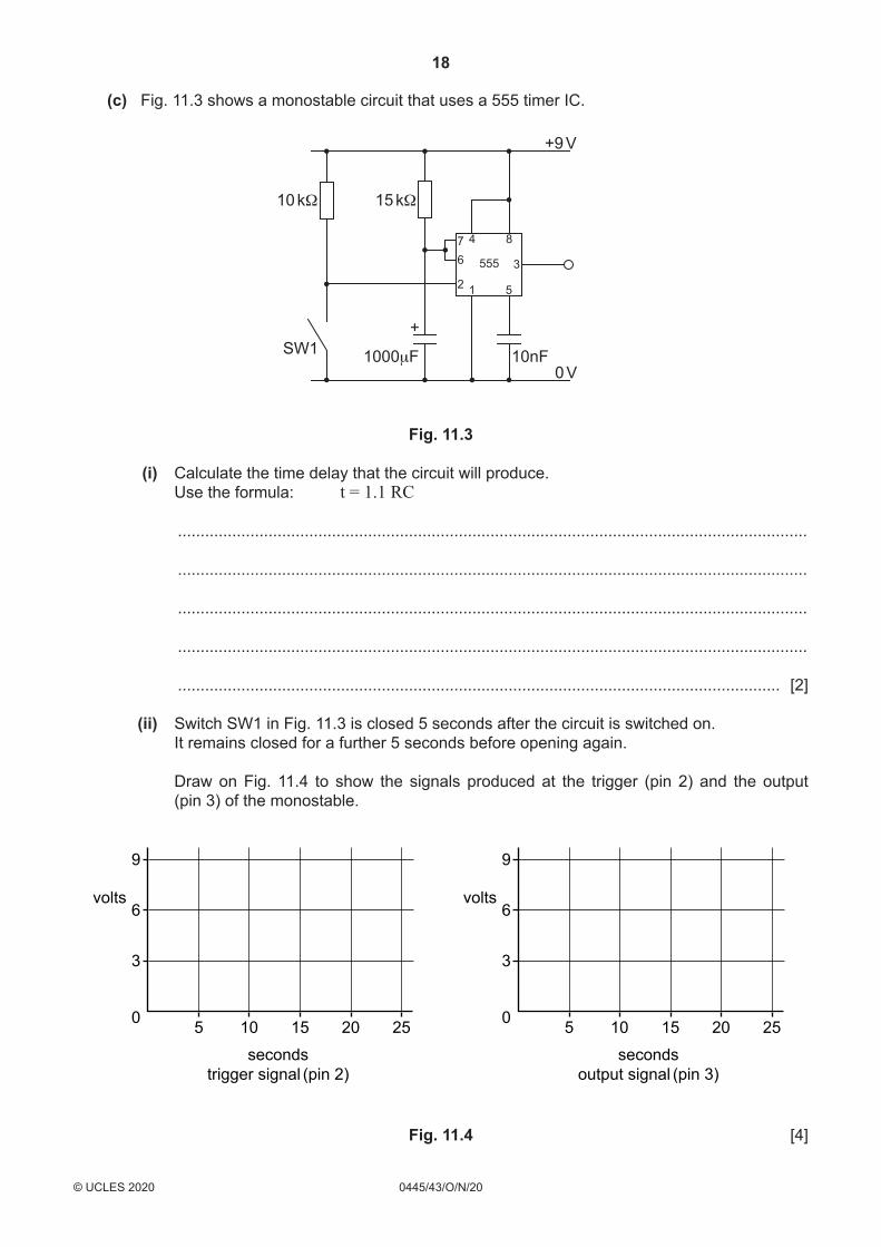
(c) Fig. 11.3 shows a monostable circuit that uses a 555 timer IC.
10 kΩ
SW1 1000μF 10nF0 V
+9 V
76
2 1 5
3
84
555
+
15 kΩ
Fig. 11.3
(i) Calculate the time delay that the circuit will produce. Use the formula: t = 1.1 RC
...........................................................................................................................................
...........................................................................................................................................
...........................................................................................................................................
...........................................................................................................................................
..................................................................................................................................... [2]
(ii) Switch SW1 in Fig. 11.3 is closed 5 seconds after the circuit is switched on. It remains closed for a further 5 seconds before opening again.
Draw on Fig. 11.4 to show the signals produced at the trigger (pin 2) and the output (pin 3) of the monostable.
9
6
3
0 5 10 15
secondstrigger signal (pin 2)
volts
20 25
9
6
3
0 5 10 15
secondsoutput signal (pin 3)
volts
20 25
Fig. 11.4 [4]
19
0445/43/O/N/20© UCLES 2020
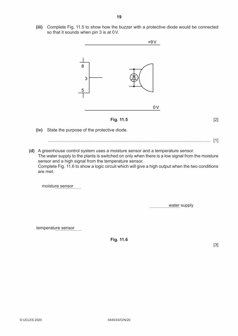
(iii) Complete Fig. 11.5 to show how the buzzer with a protective diode would be connected so that it sounds when pin 3 is at 0 V.
3
5
8
0 V
+9 V
Fig. 11.5 [2]
(iv) State the purpose of the protective diode.
..................................................................................................................................... [1]
(d) A greenhouse control system uses a moisture sensor and a temperature sensor. The water supply to the plants is switched on only when there is a low signal from the moisture
sensor and a high signal from the temperature sensor. Complete Fig. 11.6 to show a logic circuit which will give a high output when the two conditions
are met.
moisture sensor
water supply
temperature sensor
Fig. 11.6 [3]

20
0445/43/O/N/20© UCLES 2020
Permission to reproduce items where third-party owned material protected by copyright is included has been sought and cleared where possible. Every reasonable effort has been made by the publisher (UCLES) to trace copyright holders, but if any items requiring clearance have unwittingly been included, the publisher will be pleased to make amends at the earliest possible opportunity.
To avoid the issue of disclosure of answer-related information to candidates, all copyright acknowledgements are reproduced online in the Cambridge Assessment International Education Copyright Acknowledgements Booklet. This is produced for each series of examinations and is freely available to download at www.cambridgeinternational.org after the live examination series.
Cambridge Assessment International Education is part of the Cambridge Assessment Group. Cambridge Assessment is the brand name of the University of Cambridge Local Examinations Syndicate (UCLES), which itself is a department of the University of Cambridge.
BLANK PAGE