Embed Size (px)
Citation preview

IJSRD - International Journal for Scientific Research & Development| Vol. 7, Issue 07, 2019 | ISSN (online): 2321-0613
All rights reserved by www.ijsrd.com 388
Design, Analysis & Fabrication of the Power-train System for All-terrain
Vehicle
Mr. Vedang. D. Sharma1 Mr. Kshitij. N. Sable2 Mr. Vaishnav. N. Saykar3 Mr. Vijay. D. Zarkar4
1,2,3,4Department of Mechanical Engineering 1,2,3,4PCET’S Pimpri Chinchwad College of Engineering and Research, Plot No. B, Sector no. 110,
Ravet, Pune- 412101, India
Abstract— SAE BAJA is a national level All-Terrain Vehicle
building and racing competition, the main objective of this
paper is to design analyse and fabricate a reliable and efficient
powertrain unit for an All-Terrain Vehicle. Powertrain
system comprises an Engine, Transmission unit, Drive axle,
Tyres. Purpose of design is that the vehicle must carry
approximately one ton of load for 100ft, the vehicle must not
get stuck in the mud pool and pass easily, the must be able to
climb the grad ability with minimum drive slip and while
performing the system must be reliable and system must not
fail under any circumstance. During the designing phase of
the system, the focus was on to minimize the weight and
while doing this optimize the expense without any hamper to
the performance and reliability of the system. This paper’s
purpose is to study the system and the designing of the two
stage gear reducing unit, coupling and aligning methods for
CVT (continuously variable transmission) with engine and
the double reduction gear train system. Briggs and Stratton
engine with 10hp @ 3200 RPM and 18.9 N-m @ 2600 RPM
was selecting as power producing device, CVTech CVT with
0.4:1 as higher ratio and 3:1 as lower ratio was selected for
transmitting power at variable conditions, a double stage
reduction gear train system was used for the to compensate
the torque requirement, TATA NANO drive axle were
selected for the power transmission purpose from gear train
to the wheels. The designing was done one CATIA V5 R21
and assembly were done on PTC Creo 3.0. The design has
been evaluated by using FEA software like ANSYS 19.1.
Further in the manufacturing phase the gear train casing was
machined on vmc, shaft were made on centre lathe machine,
and gears were made using hobing process. Hence, all the
components were assembled and proper testing was carried
out to get the practical evidence of the performance and
reliability of the system for the rough terrain as there are in
the actual competition.
Keywords: All- Terrain Vehicle Engine, CVT, Gearbox,
Drive axle, Tire, Catia, Ansys
I. INTRODUCTION
Today people in the field of automotive engineering such as
researchers and designers are continuously looking to
accomplish two tasks. They work to improve the current
designs, but also to teach and inspire the coming generation
of engineers to take an interest in the challenges to evolve the
future of automotive engineering in brighter side. So to help
them in their mission, a global association named as the
Society of Automotive Engineers (SAE) was formed. The is
an international society which host different competitions like
BAJA SAE, FORMULA SAE, TIFAN SAE and now a days
they have also started to host completion based on solar and
electric powered vehicle. All these competitions help students
to develop their knowledge and get hands on experience on
the project making them market ready.
Today people in the field of automotive engineering
such as researchers and designers are continuously looking to
accomplish two tasks. They work to improve the current
designs, but also to teach and inspire the coming generation
of engineers to take an interest in the challenges to evolve the
future of automotive engineering in brighter side. So to help
them in their mission, a global association named as the
Society of Automotive Engineers (SAE) was formed. The is
an international society which host different competitions like
BAJA SAE, FORMULA SAE, TIFAN SAE and now a days
they have also started to host completion based on solar and
electric powered vehicle. All these competitions help students
to develop their knowledge and get hands on experience on
the project making them market ready
Today people in the field of automotive engineering
such as researchers and designers are continuously looking to
accomplish two tasks. They work to improve the current
designs, but also to teach and inspire the coming generation
of engineers to take an interest in the challenges to evolve the
future of automotive engineering in brighter side. So to help
them in their mission, a global association named as the
Society of Automotive Engineers (SAE) was formed. The is
an international society which host different competitions like
BAJA SAE, FORMULA SAE, TIFAN SAE and now a days
they have also started to host completion based on solar and
electric powered vehicle. All these competitions help students
to develop their knowledge and get hands on experience on
the project making them market ready.
BAJA SAE is a competition in which under graduate
students from different colleges have to make an ATV as per
the norms given in the form of rulebook. The score in the
competition is given on the basis of static judging, which
includes designing, validating, sales and cost; the other part
of the evaluation is based on the dynamic evets like
suspension traction, mauverability, rock crawl, acceleration
and the most important the four hour endurance race.
In an ATV there are mainly six department roll cage,
powertrain, suspension, steering, brakes and marketing. This
paper is focused on the study, designing, analysis and
fabricating of the powertrain system for an ATV. The primary
function for a powertrain system is to transfer the power for
the engine to the wheels with minimum amount of loss and
manoeuver the vehicle within all possible terrain that includes
rocky, muddy road with water and with a climb. Powertrain
has the most important task of all the other departments, the
system must be bring proper stability to the ATV along with
the performance. The vehicle must able to accelerate when
need must be able to produce proper power and required
torque with minimum or with no wheel spin. It is required to
have minimum wheel spin to keep the losses at minimum
level.

Design, Analysis & Fabrication of the Power-train System for All-terrain Vehicle
(IJSRD/Vol. 7/Issue 07/2019/090)
All rights reserved by www.ijsrd.com 389
Powertrain system for an ATV is very vast. There
are different layout of powertrain system such as 4- wheel
drive, all wheel drive, front wheel and rear wheel drive. Each
of these type have advantages and disadvantages on the basis
of the price, weight, transferability capacity, etc. As we have
the engine with the specified power rating we know that what
are the limits. Its not like that we can’t use 4 wheel drive or
all wheel drive we can use it but the we would compromise
on many other objective which would make the design
impractical. So on the basics of practicality we have two
options i.e. front wheel drive and rear wheel drive her we
have chosen the rear wheel drive. It had many advantages in
our condition. We have then fixed the layout of the system to
transmit the power from engine shaft to the wheel. We have
selected the layout as ENGINE → CVT → 2 Stage gear
Reduction unit → Drive axle → Wheels. The main advantage
of using the following layout is that we kept the system vey
compact and we get the minimum amount loss in the system.
The CVT which we used is the CVTech CVT with 0.3:1 as
higher ratio and 3:1 as lower ratio.
This paper is focused on the design, analysis,
fabrication and assembly of all the different units in the
powertrain system on the chassis. While designing we need
to make sure that all other sub-systems of the ATV are
properly synchronized with the powertrain sub-system. It is
very necessary that wheels must be properly aligned so that
there is no unwanted drag which reduces the efficiency.
While designing we have to take certain assumptions.
Following are those:-
1) Wheel Base
2) Wheel Track
3) Sprung + Unsprung (Kerb Weight)
4) C.G. Height
5) Gradability
II. LITERATURE REVIEW
V.B.Bhandari [9] have given a precise description regarding
designing of components. The designing of powertrain starts
with Selecting Gear pair, calculating module and gear ratio
for the gearbox. Firstly we calculate the module from given
parameters like engine power, engine rpm, number of teeth’s
on gear, factor of safety and velocity ratio. Velocity ratio is
calculated by considering speed of the vehicle. Module is
calculated for number of stages present in the gearbox. We
get all parameters which are essential to manufacture a gear.
The next important thing is designing of shaft. Shafts are
designed using SFD (Shear Force Distribution Diagram) and
BMD (Bending Moment Diagram). Tangential and Radial
forces acting on shaft because of the gear pair are calculated.
Torsion theory is used to design shaft this make sure that shaft
is safe in twisting. Diameter of shaft varies as the torque
acting on it varies. The next thing which is given is bearing
calculations, according to load acting on the shaft bearing is
selected form number of types. Life of bearing is an important
factor which affects the working of bearing. Load acting on
bearing is calculated from the radial load of the gear and it is
made sure that the bearing selected should have more load
caring capacity than the calculated bearing load. This ensures
that the bearing selected will sustain to its reliable life time.
Based on the shaft diameter and load acting on the bearing,
standard bearing is selected from the catalogue given in the
book.
P.S.G [8] have given a brief explanation regarding
material selection and its standard method of designing.
Material is selected by considering various factors like nature
(ductile or brittle), yield strength, ultimate tensile strength,
and poisons ratio. Hardening of material is very important if
material in order to make proper functioning of material.
Keys are used to lock gear with shaft, it prevents relative
motion between gear and shaft. Dimension of key and
keyways are taken from the standard table. Manufacturing of
keyway is done by milling machine by considering this
standard table. Splines are also used to stop the relative
motion and hence transmit power from gear to shaft. In
sliding mesh gearbox spline are used to slide gear in order to
achieve variable reduction ratio. Drive shaft is connected to
output shaft of gearbox with the help of spline this ensures
that there are least power losses in transmission line.
According to theory stress concentration occurs at outer
periphery so weight reduction is done on gears. I-section and
holes are drilled on periphery of gear in order to reduce
weight without affecting its transmission efficiency.
Thickness of gearbox casing is calculated with the help of
data provided. It is made sure that material selected has
adequate factor of safety in order to avoid any failure. Proper
Tolerance is provided in order to achieve desired fit between
two surfaces. By considering shaft basis and hole basing
system proper value of tolerance is find out from the table.
This helps in proper fitting and roughness symbol is provided.
Eric Payne [1] have mentioned in his paper that how
to design gearbox by considering ground conditions in order
to run vehicle in any environment. Design of components
should be such that it will be easy for manufacturing.
Lubrication is very important parameter as it reduces friction
and increases vehicle performance. Tires are selected by
considering its groove pattern, width of the tire affect traction
of vehicle. CVT (Continuously varying transmission) is used
to get variable reduction. Clutch is eliminated by using CVT
hence no need to use shifter. The layout of system should be
designed in such a way that it should worked in more efficient
way. Sled pull is an event where max torque is required hence
gearbox should be designed such that it satisfy all parameters.
Engine graph is studied and engine rpm at different load is
found out. Testing of vehicle should be done in order to
sustain in any condition. It must absorb all fatigue load acting
on it.
III. OBJECTIVE AND METHODOLOGY
The objective of this paper is to design, analyses, and
fabricate the suspension system for an All-Terrain Vehicle.
The objective are as follows -
1) A detailed study of the powertrain system of a vehicle
2) To transmit the sufficient TORQUE and POWER to
generate the required TRACTIVE EFFORT with
minimum tire slip.
3) Design for optimum REDUCTION RATIO keeping in
mind the WEIGHT, ACCELERATION, GRADE-
ABILITY and MAX SPEED requirements.
4) Cost reduction
5) To support rear suspension system.

Design, Analysis & Fabrication of the Power-train System for All-terrain Vehicle
(IJSRD/Vol. 7/Issue 07/2019/090)
All rights reserved by www.ijsrd.com 390
The methodology adopted is as following:-
1) Complete and detailed study of the topic with
alternatives.
2) Making proper assumptions of certain parameters and
calculating all the pre-requisite parameters to start the
design.
3) Study of Engine Performance Characteristics.
4) Survey of Various CVTs and Study of Efficiency and
Tuning Parameters.
5) Calculation for Max Traction and Final Drive Ratio:-
The maximum traction for wheel slip was calculated initially.
Based on this value the final drive ratio was calculated. After
considering the desired vehicle performance in terms
acceleration, grade-ability, max speed and the various losses
like rolling resistance, aerodynamic drag (very negligible)
and the inertia losses, the exact final drive ratio was
calculated.
6) Design and Analysis of Two Stage Speed Reducer:
The design of the gears, shaft and casing was done with the
help of standard procedures and data books. The bearings
were selected according to a standard procedure from the
manufacturer’s catalogue.
7) Subsystem Integration- Chassis:
The engine, CVT and the gearbox need to be mounted on the
roll cage. The mounting of the gearbox and engine was
designed keeping in mind the serviceability of the
components.
8) Design and Selection of Drive Components:
Various other drive components like the Tripodal joints and
shafts are selected on the basis of various parameters like max
torque transmitted and the length of the shaft.
9) Subsystem Integration- REAR SUSPENSION:
The shafts and the Tripodal joints have to be coupled to the
suspension system and the wheels in order to transmit the
required power and torque. This is done along with the
suspension team.
10) Analyzing and validating the design.
A. Assumptions:
Mass 250 kg
Weight 2452.5 N
Wheel-base 54 inches= 1.3716 m
Rear Wheel-
track 47 inches= 1.175 m
C.G height 20 inches= 0.508 m
C.G front 0.41148 m
C.G rear 0.96012 m
Wheel radius 11.5 inches= 0.2921 m
Efficiency 90%
Acceleration 1.5 m/s2
Ø 35o
Engine
305 cc Briggs & Stratton, Single
Cylinder Petrol Engine, Output Torque-
18.9 N-m at 2600 rpm
IV. DESIGN DESCRIPTION
A. Calculating over Losses and Drag forces:
1) Wheel Resistance (FR):
Wheel resistance comprises the resisting forces acting on the
rolling wheel. It is made up of rolling resistance, road surface
resistance and slip resistance. Figure shows the forces and
torques acting on the wheels. The integral of the pressure
distribution over the tire contact area gives the reaction force
R. It is the same as the wheel load GR. Because of the
asymmetrical pressure distribution in the wheel contact area
of the rolling wheel, the point of application of the reaction
force R is located in front of the wheel axis by the amount of
eccentricity.
The dimensionless proportionality factor Fr is
designated as the rolling resistance. Values of rolling
resistance Fr: Very good earth tracks: 0.045 Bad earth
tracks: 0.60 Loose sand: 0.150-0.130 Smooth tarmac road:
0.010 Bad worn road surface: 0.035
2) Air Resistance:
The air resistance is made up of the pressure drag including
induced drag (turbulences induced by differences in
pressures), surface resistance and internal (through-flow)
resistance. Drag is calculated by,
FL = (½) ρLcWAv2
Where, ρL is 1.199 kg/m3 and cW (coefficient of
drag) is taken as 1.2. We have considered it to be negligible.
3) Gradient Resistance:
The gradient resistance or downhill force relates to the slope
descending force and is calculated from the weight acting at
the centre of gravity.
Fst =W.sinαSt; αSt = 35o (assumed)
FST = 860 N
4) Acceleration Resistance:
Inertial forces also occur during acceleration and braking.
The total mass of the vehicle and the inertial mass of the
rotating parts of the drive acceleration or brakes are the
factors influencing the resistance to acceleration:
FA = m.a = 375 N
5) Total Driving Resistance:
The traction FZ, required at the drive wheels is made up of the
driving resistance forces described above, and is defined as:
FZ = FR + FST + FA
FZ= 1835 N
B. Torque Calculations:
Torque= Fz * Rstat = 1835* 0.2921
T= 536 N-m
System efficiency= 90% (assumed)
Design, Analysis & Fabrication of the Power-train System for All-terrain Vehicle
(IJSRD/Vol. 7/Issue 07/2019/090)
All rights reserved by www.ijsrd.com 391
Actual Torque Tact = 536/ 0.9= 595 N-m
Final drive torque= Tact + T= 595 + 30 (Inertial torque)
TF= 625 N-m
C. Reduction Ratio Calculations:
Overall reduction ratio= Final drive torque
Engine torque=
625
18.9
= 33
Gear train reduction ratio= Overall reduction ratio
CVT lower ratio=
33
3 = 11
CVT Higher reduction ratio- 0.3 ….. (For CV- Tech CVT)
CVT Lower reduction ratio- 3 …….. (For CV- Tech CVT)
D. Gear Parameters Calculations:
Here, we assume number of teeth on pinion; ZP1= ZP2= 18
Using Hunting Tooth Theory, we find the number of teeth on
gears for 1st & 2nd stage.
Therefore, No. of teeth on intermediate gear = ZG1 = 55
No. of teeth on intermediate gear = ZG2 = 65
A = 6 ∗ 106
π. [
Kw∗Cs∗f(s)
ZG∗NG∗Cv∗10∗Sut
3
]
Module (m) = A1
3
Module (m1) for stage 1= 1.75 mm
Module (m2) for stage 1= 2.25 mm
E. Shaft Calculations (By ASME method):
D3=16
π∗τ∗ √[KbMb]2 + [KtMt]2
Thus, D1= Input shaft diameter = 15 mm
D2= Intermediate shaft diameter = 25 mm
D3= Output shaft diameter = 35 mm
F. Bearing Calculations:
L10 = L10h*60*N/106
C = P*(L10) 1/3
Where,
C= Bearing load (N)
L10h= Bearing life= 500 hours (assumed)
Hence, Input Bearing selected – 6004 (from Manufacturer’s
Catalogue)
Intermediate Bearing selected – 6205 (from Manufacturer’s
Catalogue)
Output Bearing selected – 6007 (from Manufacturer’s
Catalogue)
G. Key Calculations:
The dimensions of the key are selected directly from the PSG
Data book.
Key 1= 4*4 mm
Key 2= 5*5 mm
H. Gear and Bearing Housing:
The design was done from V.B. Bhandari Data Book. In this
standard thickness and spacing were given. Taking it as a
reference we have designed our casing considering other
parameters like the brake caliper mounting, mounting points
for the gear-train on the chassis, serviceable mounting for the
casing closer so that it doesn’t become a barrier in any parts
during the assembly.
I. Drive Shaft Calculations:
The drive shaft taken is the OEM drive shaft of Tata Nano
Model. The selection is done because it meets the
requirements of total articulation angle & drive shaft
diameter.
J. Design using Catia:
Engine CAD model
CVT Assembly CAD model
Pinion shaft CAD model
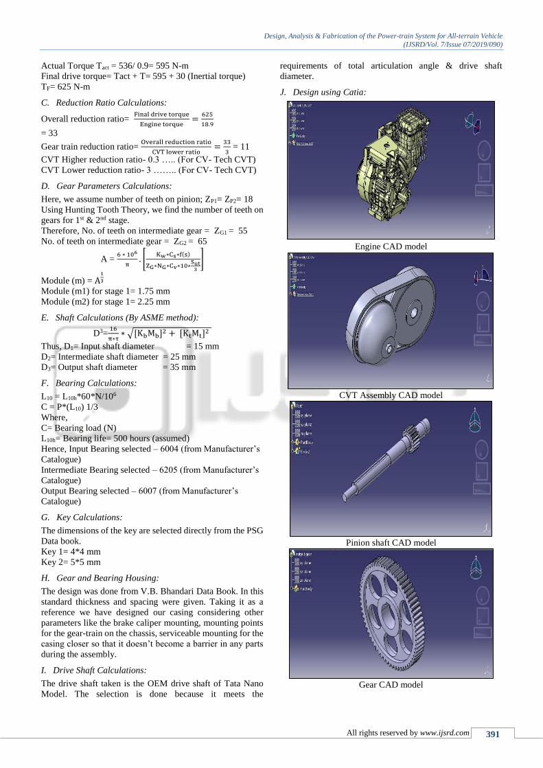
Gear CAD model

Design, Analysis & Fabrication of the Power-train System for All-terrain Vehicle
(IJSRD/Vol. 7/Issue 07/2019/090)
All rights reserved by www.ijsrd.com 392
Left Gearbox Casing CAD model
K. Right Gearbox Casing CAD model with inboard caliper
mount
CVT Assembly
Input Shaft Drafting
Gear Drafting
Assembly Exploded View
L. CAE of Components:
CAE is a very important step in any design process. The
components which were designed for the ATV is then
rigorously tested in the CAE software for the real world
conditions. By performing CAE we get the data related to the
strengths, weakness and other factors like reliability & life of
the component. This data then can be helpful in optimizing
the design to the best possible way.
In the below images, the result of analysis is shown
which were done on ANSYS 19.1. Different values were
taken into consideration such as maximum torque transmitted
by the shaft, maximum braking force. The maximum stresses
induced in the checked and then the FOS is calculate for the
component. The mesh used for the analysis is tetrahedron and
Hex-dominant element and mesh size used is in between 3-4
mm. Static structural analysis was performed on the
component. The main objective for performing the analysis
was weight reduction without making the component
complex which would lead to high manufacturing cost.
The procedures which were followed as below:-
1) Entering the engineering data of the material.
2) Importing the geometry in a specific CAD model
compatible with ansys e.g. .iges format.
3) Showing the contact position for the meshed gears.
4) Setting the mesh shape, size and quality.
5) Applying the torque and the constraint on the component.
6) Selecting the solver.
7) Solving the problem.
8) Check out the values for different results whichever are
required and then analyze it whether they are in the
permissible limits or not.

Design, Analysis & Fabrication of the Power-train System for All-terrain Vehicle
(IJSRD/Vol. 7/Issue 07/2019/090)
All rights reserved by www.ijsrd.com 393
After evaluating the results see whether they are within
your acceptable range or not and then take the desired action.
Following are the places where the torque and constraints is
to be applied while performing analysis on gear, it is as
follows:-
1) Apply fixed support on the inner part of the gear.
2) Give frictionless support to pinion shaft.
1) Apply Torque on the Pinion.
Meshing of Pinion and Gear
Static Structural analysis of Pinion and gear
Fig. 3.1.10: (b)
Material - 20MnCr5
Syt - 800Mpa
Max. stress - 575Mpa
FOS - 1.39
M. Manufacturing:
As most of the components in the system are made from solid
metal billet we have use different machining process. For
manufacturing of the gear-train casing we have use 3-Axis
VMC machine, it almost took 10 to 12 machine hours for
making both side of the casing. The shaft were firstly
machined on the conventional lathe machine and then gears
that were integrated on the shaft were put on hobbing
machine for gear cutting process. It took almost an hour for
pinion and about 3-4 hour for the bigger gears to be
manufactured. After that the output shaft was further been
processed for internal spline cutting so that we can integrate
it with the Tripod axle. After all the manufacturing process
were done then the gears and the shaft were further moved on
for hardening.
The mounting for the engine were made of square
pipes and they were welded with the chassis using TIG
welding and the mounting for the gear-train was of circular
pipe. According to the rules given by SAE INDIA we also
manufactured CVT casing
The bearing used were of SKF and they were
selected by using standard process and using manufacturing
catalogues. The nylon nut and hardened bolts with hardness
above 8.8 were used for fastening the components.
Engine
CVT
Tires
Design, Analysis & Fabrication of the Power-train System for All-terrain Vehicle
(IJSRD/Vol. 7/Issue 07/2019/090)
All rights reserved by www.ijsrd.com 394
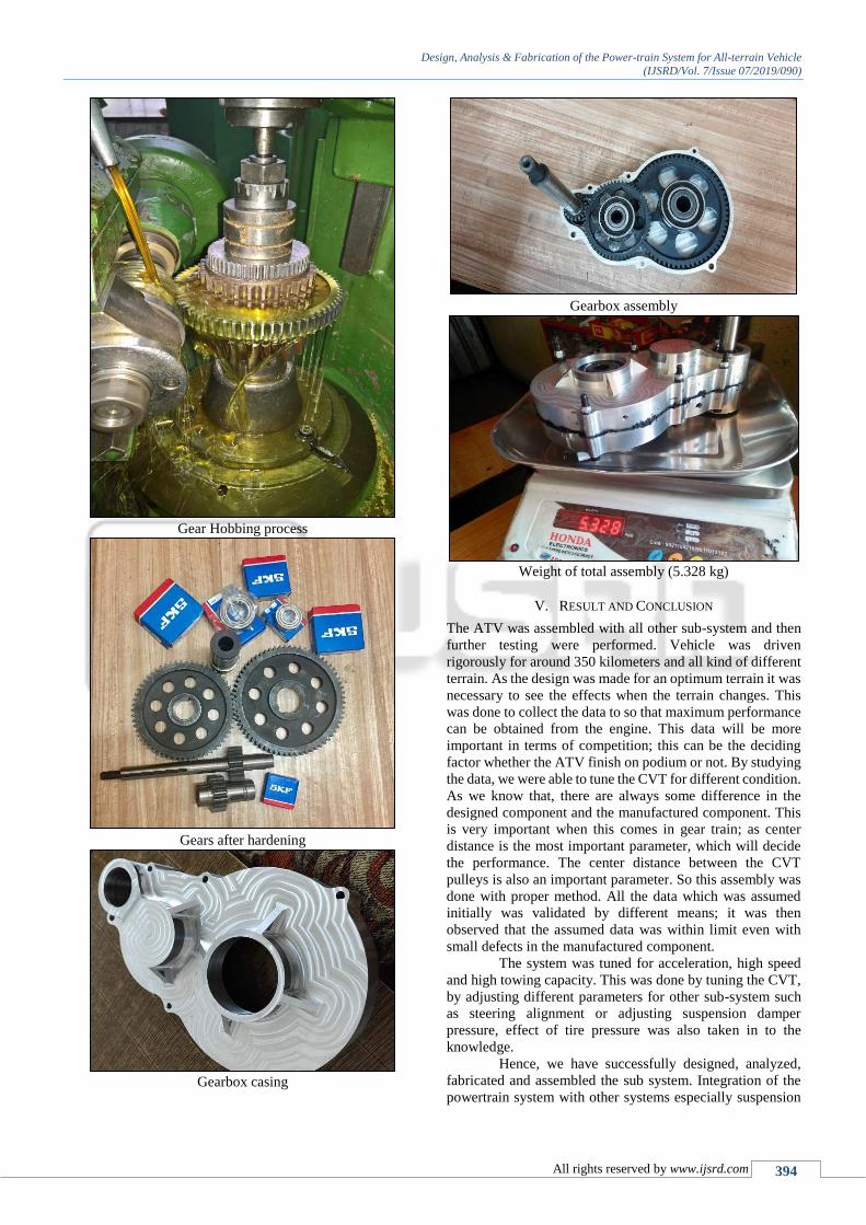
Gear Hobbing process
Gears after hardening
Gearbox casing
Gearbox assembly
Weight of total assembly (5.328 kg)
V. RESULT AND CONCLUSION
The ATV was assembled with all other sub-system and then
further testing were performed. Vehicle was driven
rigorously for around 350 kilometers and all kind of different
terrain. As the design was made for an optimum terrain it was
necessary to see the effects when the terrain changes. This
was done to collect the data to so that maximum performance
can be obtained from the engine. This data will be more
important in terms of competition; this can be the deciding
factor whether the ATV finish on podium or not. By studying
the data, we were able to tune the CVT for different condition.
As we know that, there are always some difference in the
designed component and the manufactured component. This
is very important when this comes in gear train; as center
distance is the most important parameter, which will decide
the performance. The center distance between the CVT
pulleys is also an important parameter. So this assembly was
done with proper method. All the data which was assumed
initially was validated by different means; it was then
observed that the assumed data was within limit even with
small defects in the manufactured component.
The system was tuned for acceleration, high speed
and high towing capacity. This was done by tuning the CVT,
by adjusting different parameters for other sub-system such
as steering alignment or adjusting suspension damper
pressure, effect of tire pressure was also taken in to the
knowledge.
Hence, we have successfully designed, analyzed,
fabricated and assembled the sub system. Integration of the
powertrain system with other systems especially suspension

Design, Analysis & Fabrication of the Power-train System for All-terrain Vehicle
(IJSRD/Vol. 7/Issue 07/2019/090)
All rights reserved by www.ijsrd.com 395
system is been successfully done. We had successfully
completed the SAE BAJA INDIA without any failure in
power-train system and neither in any other department. Yes
there is more scope of improvement.
BAJA Vehicle (2018-2019)
REFERENCES
[1] Eric Payne, BSME, The University of Akron, Richard
Gross, Emeritus Professor of Mechanical Engineering,
The University of Akron, Zips Baja Off-Road Racing
2015 Powertrain Design, Fabrication, and Testing, The
Dr. Gary B. and Pamela S. Williams Honors College,
Eric T. Payne, The University of Akron 2015.
[2] Abdulrahman Almuflih, Andrew Perryman, Caizhi
Ming, Zan Zhu, Ruoheng Pan Team 02, SAE Mini Baja
Drivetrain, Mechanical Engineering Design I – Fall
2013.
[3] Dylan Stimson, Jason Mehta, Kenneth McPherson, Ryan
Horton, Professor David Planchard, SAE Baja Major
Qualifying Project Final Report, 04/28/2016.
[4] Team 6: Erin Ebsch, Jenna Kudla, Calvin O’Brien, and
Bridget Quick, ME 450 Final Report Baja Gear
Reduction, Fall 2012.
[5] Gillespie, T., Fundamentals of Vehicle Dynamics,
Society of Automotive Engineers, Inc., Warrendale.
[6] http://www.cvtech-aab.com/en/
[7] https://www.briggsracing.com/racing-engines/model-19
[8] PSG College of technology, Design Data Book,
Kalaikathir Ahchagam, ISBN-978-81-927355-0-4,
India.
[9] Bhandari, V.B., Design of Machine Elements, 3rd
edition, Tata McGraw-Hill Education (India) Pvt. Ltd.,
Delhi, 2014, ISBN-13: 978-0-07-068179-8, ISBN-10: 0-
07-068179-1, India.
[10] Dr. Kirpal Singh, Automobile Engineering Vol-1,
STANDARD PUBLISHES DISTRIBUTORS (2017),
ISBN-10: 8180142426 ISBN-13: 978-8180142420,
India.
[11] Dr. Kirpal Singh, Automobile Engineering Vol-2,
Standard (2011), ISBN-10: 8180141772ISBN-13: 978-
8180141775, India.