Embed Size (px)
Citation preview

International Journal of Applied Engineering Research ISSN 0973-4562 Volume 13, Number 16 (2018) pp. 12570-12581
© Research India Publications. http://www.ripublication.com
12570
Design and analysis of a Dual band Monopole Antenna for resonating
between Wi-Fi & Wi-Max Applications
1Mr. Prasanna Paga,2Dr. H.C.Nagaraj,3Dr.T.S.Rukmini
1Research Scholar, 2Professor & Principal, 3Professor, 1,2,3Department of Electronics and Communication Engineering, NREA,
Nitte Meenakshi Institute of Technology, Yelahanka, Bangalore, Karnataka, India.
Abstract
In the proposed work, a dual band antenna has been designed,
simulated and fabricated on a Rogers (RT/Duroid 5880tm)
substrate of permittivity 2.2 and thickness 1.6mm for resonating
between Wi-Fi and Wi-Max. The novely of the work lies in
using two conducting strips that are mutually perpendicular to
each other loaded with a partial ground plane. The proposed
structure resulted in a peak Gain of 7.62dB and 5.75dB for the
lower and the upper frequency bands respectively.
Keywords: Wi-Fi, Wi-Max, Monopole
INTRODUCTION
In recent years there has been a tremendous development in
the field of wireless communications. With the explosive
growth of different wireless standards supporting different
frequencies, the Antennas used in these devices need to
support a large number of wireless standards such as GSM,
Wi-Fi, Wi-Max, UMTS to increase the data rate and improve
the channel capacity along with reduction in antenna size.
The current Antennas need to be replaced with reconfigurable
Antennas that can dynamically change the radiation
characteristics of the Antenna in real time such as operating
frequency, polarization or radiation pattern In [1], the
authors had designed a Monopole Antenna on a FR4 substrate
for Wi-Fi and WLAN Applications. The peak Gain remained
at 2.04 dBi and 2.83dBi for Wi-Fi and WLAN Frequency
Bands respectively. In [2], the authors designed a dual band
Frequency reconfigurable Planar Dipole Antenna loaded with
a Dual-Band Artificial Ground plane The proposed Antenna
gave a Bandwidth of 12.5% and 6.7% at 2.4GHz and 5.2 GHz
respectively. In [3], a dual band parabolic slotted Ground
plane for Wi-Fi and WLAN Applications. The proposed
Antenna resulted in a Gain of 1.68dBi and 2.33 dBi for Wi-Fi
and WLAN bands respectively. In [4], a novel compact dual-
band monopole antenna using defected ground structure
(DGS) is presented. DGS is used in this antenna which has a
rectangular patch with dual J-shaped strips. It helps in
achieving a good resonant mode and good impedance
matching. The antenna gives a bandwidth of 400MHz and
530MHz for 2.5GHz and 3.5GHz respectively. It also gives
omnidirectional pattern and constant gain for both the
frequency bands. In [5], dual band David fractal Microstrip
patch antenna for GSM and WiMAX applications has been
proposed. The antenna resonates at 1.8GHz and 3.4GHz and
gives good radiation pattern and moderate gains of 6.93dBi
and 5.3dBi for 1.8GHz and 3.4GHz respectively. The antenna
gives a return loss of -18.7dB, -14.3dB for 1.8GHz and
3.4GHz respectively. The radiating structure resulted in a -
10dB impedance bandwidth of 55MHz and 31MHz, Gain of
6.93dBi and 5.3dBi for the lower and upper bands
respectively. The radiation pattern reported were
hemispherical for 1.8GHz and horizontal figure of 8 for
3.5GHz respectively. In [6], a novel triple-band microstrip-fed
planar monopole antenna with defected ground structure
(DGS) is proposed for WLAN and WiMAX applications. The
proposed microstrip-fed antenna consists of a rectangular
patch, dual inverted L-shaped strips and a defected ground.
The designed antenna can generate three separate resonances
to cover both the 2.4/5.2GHz WLAN bands and the 3.5GHz
WiMAX bands while maintaining a small overall size of
20mm × 27mm. A prototype is experimentally tested, and
experimental results show that the antenna gives good
radiation patterns and enough antenna gains over the
operating bands. In [7], a novel design of a pentagonal-shaped
planar dual-band monopole antenna has been presented. The
validated antenna is compact with a size of 57x50x1,6 mm3.
It is printed on an FR-4 substrate and fed by a 50 Ohm
microstrip line. The final circuit operates in the DCS
frequency band at 1.8 GHz and the WiMAX at 3.5 GHz. To
achieve such antenna, we have used different optimization
methods integrated in CST Microwave Studio. The obtained
results are compared with another electromagnetic solver
Ansoft’s HFSS. After the realization, we have tested and
validated this antenna. The measurement results present an
agreement with the numerical results. The Gain reported were
0.6dB and 3.56dB for lower and upper frequency bands
respectively. In [8], a planar dual-band monopole antenna is
presented for Global System for Mobile Communications
(GSM) band applications, which also have the potential to be
used for energy harvesting system. The proposed antenna
comprises of a ground plane at the back of the FR4 substrate
and three microstrip lines which are physically connected with
each other at the top surface of the substrate. The monopole
antenna achieves good return loss at resonance frequencies of
915 MHz and 1800 MHz with a bandwidth value of 124.2
MHz and 196.9 MHz respectively. The antenna gains of 1.97
dB and 3.05 dB are achieved at resonance frequencies of 900
MHz and 1800 MHz. Experimental results show good
agreement with simulated performance. The output from the
receiving antenna is also observed in order to analyze the
relationship of the power level and the distance between
transmitting and receiving antenna. This study is an early
investigation in designing the RF energy harvesting system to

International Journal of Applied Engineering Research ISSN 0973-4562 Volume 13, Number 16 (2018) pp. 12570-12581
© Research India Publications. http://www.ripublication.com
12571
support green technology and sustain able development
particularly for Wireless Sensor Network (WSN)
applications.In [9], a compact triple-band monopole antenna
with two different slots for WLAN and WiMAX applications
is proposed and experimentally studied. The proposed antenna
with a size of 30mm × 25mm × 1mm is excited by a 50Ω
Microstrip feed line. The designed antenna obtains three
frequency bands through loading an inverted E-shaped slot
and an inverted C-shaped slot which incise the surface current
and change the path of the current on the rectangle patch. The
obtained results show that the designed antenna has
impedance bandwidths of 2.4GHz, 5.8GHz for WLAN and
3.5GHz for WiMAX. The return loss, radiation patterns and
peak antenna gains are presented using computer simulations
and measurements. In [10], a simple multiband metamaterial-
loaded monopole antenna suitable for wireless local area
network (WLAN) and Worldwide Interoperability for
Microwave Access (WiMAX) applications is proposed in this
letter. The rectangle monopole of the proposed antenna is
originally designed to resonate at around 5.2 GHz. When the
inverted-L slot is etched, the antenna produces a second
resonance at around 4.1 GHz. Then, with the addition of the
metamaterial reactive loading, the resonant frequency of the
antenna will be shifted down, and a third resonance covering
the 2.4-GHz band occurs. Consequently, the antenna can
cover the 2.4/5.2/5.8-GHz WLAN and 2.5/3.5/5.5-GHz
WiMAX bands with a very compact size of only mm.
Monopole-like radiation patterns and acceptable gains and
efficiencies have been obtained. Details of the antenna design
as well as the experimental results are presented and
discussed.
.
ANTENNA DESIGN
(a) (b)
Figure 1(a) Snapshot of the simulated Antenna (top view).
(b) Ground plane view
(a) (b)
Figure 2(a) Top view of the Fabricated prototype of antenna.
(b) Ground plane view of the antenna
METHODOLOGY
In the proposed work, a dual band Antenna has been designed,
simulated and Fabricated on a Roger’s(RT/Duroid) substrate
of permittivity 2.2 and thickness 1.6mm to tune between Wi-
Fi (2.4GHz) and Wi-Max 3.5GHz Frequency band. The
Length of the longer monopole section (L1) was selected to
tune to 2.4GHz frequency band of interest while the length of
the shorter monopole section(L2) have been selected to tune
to Wi-Max band. The length and width of the substrate have
been kept equal to 50mm × 25mm.the length and width of the
ground plane have been kept equal to 20mm× 12mm to give a
monopole like characteristic feature.
DESIGN EQUATIONS
𝐋𝟏 = 𝐋𝟐.𝟒𝐆𝐇𝐳 =𝛌𝐠
𝟒
(1)
Where L1=Length of the Main Monopole resonating at
2.4GHz.
𝜆𝑔=Guide wavelength.
𝜆𝑔 =𝜆0
√𝜀𝑟𝑒𝑓𝑓
(2)
Where 𝜀𝑟𝑒𝑓𝑓= Effective electrical permittivity of the dielectric
substrate.
𝜆0=Free space wavelength corresponding to frequency of
operation.
𝜀𝑟𝑒𝑓𝑓 = [(𝜀𝑟 + 1
2) + (
𝜀𝑟 − 1
2) (1 +
12ℎ
𝑊)
−1 2
]
(3)
Where.
εr = relative permittivity of the di-electric substrate.
W= Monopole Antenna width =3mm
h= substrate thickness=1.6mm

International Journal of Applied Engineering Research ISSN 0973-4562 Volume 13, Number 16 (2018) pp. 12570-12581
© Research India Publications. http://www.ripublication.com
12572
Z=60
√𝜀𝑟𝑒𝑓𝑓𝑙𝑛 [
8ℎ
𝑊+
𝑊
4ℎ] (4)
Where Z=50 Ohms (port Impedance),
h = substrate thickness
W=Width of the Monopole.
L2=L 3.5GHz =𝜆𝑔
4 (5)
𝜀𝑟𝑒𝑓𝑓= Effective electrical
permittivity of the di-electric
substrate
Lw =6h+W (6)
Where Ls=Substrate Length
Ws=Substrate Width.
SIMULATIONS & MEASURED RESULTS
Figure 3. Simulated return loss plot of the monopole antenna resonating at 2.4GHz and 3.5GHz on Rogers(RT/Duroid) substrate
of permittivity 2.2.The corresponding return loss values are: -35.27dB and -25.985dB at 2.4 and 3.5GHz respectively.
Figure 4. Measured return loss plot of the monopole antenna resonating at 1.9GHz and 3.66GHz clearly showing a value of -
15.69dB and -13.94dB respectively as indicated by markers 1 and 3 on Rogers(RT/Duroid) substrate of permittivity 2.2.
1.00 1.50 2.00 2.50 3.00 3.50 4.00Freq [GHz]
-37.50
-25.00
-12.50
0.00
dB
(S
(1
,1))
HFSSDesign1return loss
m1
m2
Curve Info
dB(S(1,1))Setup1 : Sw eep
Name Freq X Y
m1 2.3636 2.3636 -35.2790
m2 3.5152 3.5152 -25.9852

International Journal of Applied Engineering Research ISSN 0973-4562 Volume 13, Number 16 (2018) pp. 12570-12581
© Research India Publications. http://www.ripublication.com
12573
Figure 5. Simulated bandwidth of the monopole antenna resonating at 2.4GHz on Rogers(RT/Duroid) substrate of permittivity
2.2.The simulated values of the bandwidth reported is 0.4416GHz at 2.4GHz with -10dB impedance bandwidth extending
between 2.172GHz to 2.614GHz.
Figure 6. Simulated bandwidth of the antenna resonating at 3.5GHz on Rogers (RT/Duroid5880tm) substrate of permittivity
2.2.The -10dB impedance bandwidth extending between 3.299GHz to 3.856GHz giving a total bandwidth of 0.557GHz.
International Journal of Applied Engineering Research ISSN 0973-4562 Volume 13, Number 16 (2018) pp. 12570-12581
© Research India Publications. http://www.ripublication.com
12574
Figure 7. Measured bandwidth of the Antenna resonating at 1.96GHz on Rogers (RT/Duroid5880tm) of Substrate permittivity
2.2.From the plot, it is clear that the value of the Bandwidth obtained is 0.672GHz with a -10dB impedance bandwidth extending
between 1.7 GHz to 2.37GHz respectively as indicated by markers 2 and 3.
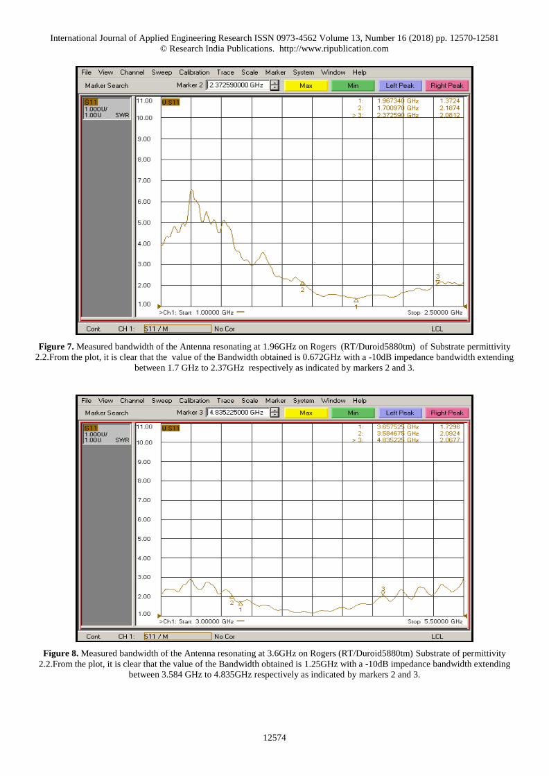
Figure 8. Measured bandwidth of the Antenna resonating at 3.6GHz on Rogers (RT/Duroid5880tm) Substrate of permittivity
2.2.From the plot, it is clear that the value of the Bandwidth obtained is 1.25GHz with a -10dB impedance bandwidth extending
between 3.584 GHz to 4.835GHz respectively as indicated by markers 2 and 3.

International Journal of Applied Engineering Research ISSN 0973-4562 Volume 13, Number 16 (2018) pp. 12570-12581
© Research India Publications. http://www.ripublication.com
12575
Figure 9. Simulated vswr plot of the antenna resonating at 2.4 GHz and 3.5GHz on Rogers (RT/Duroid5880tm) substrate of
permittivity 2.2.indicating a value of 1 and 1.12 at 2.4GHz and 3.5GHz frequency bands respectively.
Figure 10. Measured VSWR plot of the Antenna resonating at 1.96 GHz and 3.66GHz indicating a value of 1.48 and 1.52
respectively for the lower and the upper band respectively as indicated by markers 1 and 3 on Rogers(RT/Duroid) substrate of
permittivity 2.2.
1.00 1.50 2.00 2.50 3.00 3.50 4.00Freq [GHz]
0.00
50.00
100.00
150.00
200.00
225.00V
SW
R(1
)
HFSSDesign1VSWR
m1 m2
Curve Info
VSWR(1)Setup1 : Sw eep
Name Freq X Y
m1 2.4000 2.4000 1.0892
m2 3.5000 3.5000 1.1210

International Journal of Applied Engineering Research ISSN 0973-4562 Volume 13, Number 16 (2018) pp. 12570-12581
© Research India Publications. http://www.ripublication.com
12576
Figure 11. Simulated radiation pattern of the Monopole Antenna on Rogers(RT/Duroid 5880tm)substrate of permittivity 2.2
indicating a peak boresight gain of 7.49dB under H plane at 2.4GHz as shown by marker m1.The radial axis represents the Gain(
in dB) while the angular axis represents the scan angle(in degrees)
Figure 12. Simulated radiation pattern of the Monopole Antenna on Rogers(RT/Duroid 5880tm)substrate of permittivity 2.2
indicating a peak boresight gain of 7.49dB under E plane at 2.4GHz as shown by marker m1.The radial axis represents the
Gain(dB) while the angular axis represents the scan angle(in degrees)
-36.50
-33.00
-29.50
-26.00
-22.50
-19.00
-15.50
-12.00
-8.50
-5.00
-1.50
2.00
90
60
30
0
-30
-60
-90
-120
-150
-180
150
120
HFSSDesign1h-plane 2.4Ghzm1
Curve Info
dB(GainTotal)Setup1 : LastAdaptiveFreq='2.4GHz' Phi='0deg'
Name Ang Mag
m1 0.0000 7.4946
-33.00
-26.00
-19.00
-12.00
-5.00
2.00
90
60
30
0
-30
-60
-90
-120
-150
-180
150
120
HFSSDesign1e-plane 2.4Ghz
m1
Curve Info
dB(GainTotal)Setup1 : LastAdaptiveFreq='2.4GHz' Phi='90deg'
Name Ang Mag
m1 0.0000 7.4946

International Journal of Applied Engineering Research ISSN 0973-4562 Volume 13, Number 16 (2018) pp. 12570-12581
© Research India Publications. http://www.ripublication.com
12577
Figure 13. Simulated radiation pattern of the Monopole Antenna on Rogers (RT/Duroid 5880tm)substrate of permittivity 2.2
indicating a peak boresight gain of 5.66dB under H plane at 3.5GHz as shown by marker m1.The radial axis represents the
Gain(dB) while the angular axis represents the scan angle(in degrees)
Figure 14. Simulated radiation pattern of the Monopole Antenna on Rogers(RT/Duroid 5880tm)substrate of permittivity 2.2
indicating a peak boresight gain of 5.66dB under E plane at 3.5GHz as shown by marker m1.The radial axis represents the
Gain(dB) while the angular axis represents the scan angle(in degrees)
-34.00
-28.00
-22.00
-16.00
-10.00
-4.00
2.00
90
60
30
0
-30
-60
-90
-120
-150
-180
150
120
HFSSDesign1h-plane3.5Ghz
m1
Curve Info
dB(GainTotal)Setup2 : LastAdaptiveFreq='3.5GHz' Phi='0deg'
Name Ang Mag
m1 0.0000 5.6677
-36.50
-33.00
-29.50
-26.00
-22.50
-19.00
-15.50
-12.00
-8.50
-5.00
-1.50
2.00
90
60
30
0
-30
-60
-90
-120
-150
-180
150
120
HFSSDesign1e-plane 3.5GHz
m1
Curve Info
dB(GainTotal)Setup2 : LastAdaptiveFreq='3.5GHz' Phi='90deg'
Name Ang Mag
m1 0.0000 5.6677

International Journal of Applied Engineering Research ISSN 0973-4562 Volume 13, Number 16 (2018) pp. 12570-12581
© Research India Publications. http://www.ripublication.com
12578
Figure 15. Measured radiation pattern of the monopole antenna on Rogers (RT/Duroid substrate (5880tm)) and permittivity 2.2
indicating a peak bore sight gain of 5.75B under E plane at 3.5GHz, as shown by marker m1.The radial axis represents the Gain
(in dB) while the angular axis represents the scan angle( in degrees).
Figure 16. Measured radiation pattern of the monopole antenna on Rogers (RT/Duroid substrate (5880tm)) and permittivity 2.2
indicating a peak bore sight gain of 5.75dB under H plane at 3.5GHz, as shown by marker m1.The radial axis represents the Gain
(in dB) while the angular axis represents the scan angle( in degrees).

International Journal of Applied Engineering Research ISSN 0973-4562 Volume 13, Number 16 (2018) pp. 12570-12581
© Research India Publications. http://www.ripublication.com
12579
Figure 17. Measured radiation pattern of the monopole antenna on Rogers (RT/Duroid substrate (5880tm)) and permittivity 2.2
indicating a peak bore sight gain of 7.44dB under H plane at 2.4GHz, as shown by marker m1.The radial axis represents the Gain
(in dB) while the angular axis represents the scan angle( in degrees).
Figure 18. Measured radiation pattern of the monopole antenna on Rogers (RT/Duroid substrate (5880tm)) and permittivity 2.2
indicating a peak bore sight gain of 7.62B under E plane at 2.4GHz, as shown by marker m1.The radial axis represents the Gain
(in dB) while the angular axis represents the scan angle( in degrees).

International Journal of Applied Engineering Research ISSN 0973-4562 Volume 13, Number 16 (2018) pp. 12570-12581
© Research India Publications. http://www.ripublication.com
12580
Table 1. Illustrating the comparison of the simulated & measured antenna parameters for Wi-Fi and the Wi-Max band using
Rogers(RT/Duroid 5880tm) substrate of 2.2 permittivity.
Sl
No
Antenna
parameters
Simulated Simulated Measured Measured
1 Resonant
Frequency
2.4GHz 3.5GHz 2.0GHz 3.66GHz
2 Return loss -35.27 dB -25.985dB -15.69dB -13.94dB
3 VSWR 1.08 1.12 1.48 1.52
4 Gain 7.49dB
( E&H)
5.66dB
(E &H)
7.44dB(H)
7.62dB(E)
5.75dB
(E&H)
5 Bandwidth 441MHz 557MHz 0.672GHz 1.25GHz
6 Frequency
range
2.172GHz to 2.614GHz 3.299GHz to
3.856GHz
1.7 GHz-2.37GHz 3.584 to 4.835GHz
7 Radiation
pattern
Figure of 8 under E plane and
Hemispherical under H plane
Nearly Omni directional
under E plane and H plane
Omni Directional Omni Directional
VI RESULTS AND DISCUSSIONS
From the Table 1, the simulated return loss values were close
to -35.27dB and -25.985dB in the lower and the upper
frequency bands respectively indicating that the antenna
radiates reasonably well in the Wi-Fi and the Wi-Max (3.5
GHz) frequency bands respectively. The simulated VSWR
values were below 1.5 signifying that the impedance matching
has been proper in Wi-Fi and Wi-Max frequency bands
respectively. The simulated and the measured gains agree
well. The structure resulted in a nearly omnidirectional
radiation pattern along the elevation plane and characterized
by the presence of nulls along the azimuth plane with a peak
boresight gain of 5.75dB in the Wi-Max band as shown in
Figure 15 and 16. While in the Wi-Fi band, the measured
radiation pattern were omni under E plane and characterized
by the presence of Nulls under H plane with a peak boresight
gain of 7.62dB.The simulated and the measured bandwidths
agree well. The measured bandwidths reported were 672MHz
and 1.25GHz for the lower and the upper frequency bands
respectively. The measured bandwidths were significantly
higher in the Wi-Max band when compared with the Wi-Fi
band.
Figure 19. Comparison of the simulation and measured results of various Antenna performance parameters such as Resonant
Frequency, Return Loss, VSWR, Gain and Bandwidth of the simulated and Fabricated Dual band Antenna resonating between
Wi-Fi(2.4GHz) and Wi-Max(3.5GHz).
-40
-35
-30
-25
-20
-15
-10
-5
0
5
10
Simulated Rogers 2.4GHz
Simulated Rogers 3.5GHz
Measured Rogers 2.4GHz
Measured Rogers 3.5GHz

International Journal of Applied Engineering Research ISSN 0973-4562 Volume 13, Number 16 (2018) pp. 12570-12581
© Research India Publications. http://www.ripublication.com
12581
CONCLUSION
The simulated return loss values are close to -35.27 dB & -
25.985dB indicating that the antenna radiates more efficiently
in both the bands. The simulated vswr values are close to 1
in both the bands designed on Rogers indicating a good
impedance matching. The simulated and the measured Gains
agree well. The lowest reported Gain were 5.75dB in the
3.5GHz band while the highest reported value of the Gain
were 7.62dB under E plane at 2.4GHz.The total Gain
variation were in the range of 5.75dB to 7.62dB .The
measured gains were comparatively higher in the 2.4GHz
band when compared to 3.5GHz band. The measured
Bandwidths reported were 672MHz (Wi-Fi band) and
1.25GHz (Wi-Max band).The measured bandwidths were
significantly high in the Wi-Max band when compared to Wi-
Fi band. The measured radiation patterns were Omni
directional under E plane and characterized by the presence of
nulls under H plane with a peak boresight gain of 7.62dB in
the lower frequency band of interest.In the upper and the
pattern were Omni directional under E plane and associated
with nulls under H plane with a peak boresight gain of
5.75dB.
ACKNOWLEDGMENT
The Authors would like to Dr.Chandrika Sudheendra,Group
Director, ADE and Mr.Diptiman Biswas, Scientist ‘F”, ADE
for allowing us to use their facility for antenna
Characterization and radiation pattern measurement in the
Anechoic chamber.
REFERENCES
[1] S.A.Shah, M.F.Khan, S.Ullah,"Design and
measurement of Planar Monopole Antennas for
Multi-Band Wireless Applications”, IETE Journal of
Research, 2017.
[2] AdeelAfridi, SadiqUllah, ImadAli, ShahbazKhan,
James A Flint,"Design and Parametric Analysis of a
DualBandFrequency Reconfigurable Planar Dipole
Using a Dual Band Artificial Ground plane”, IETE
Journal of Research, Vol. 60, No. 1, Jan-Feb 2014.
[3] M.Z.M.Nor, S.K.A, Rahim, M.I.Sabran,
F.Malek,"Dual band, parabolic, slotted ground plane
directive antenna for WLAN Applications”, Journal
of Electromagnetic waves and Applications, Vol. 27,
No. 2, 2013.
[4] Li.Li, Shu-Hua. Rao, Bin.Tang and Ming-fu.Li, “A Novel Compact Dual-band Monopole Antenna using Defected Ground Structure”, 2013 International
Workshop on Microwave and Millimeter Wave
Circuits and System Technology
[5] Jacob Abraham, Thomaskutty Mathew, “Dual Band
David Fractal Microstrip Patch Antenna for GSM
and WiMAX Applications”, Wireless Engineering
and Technology, Vol.6, pp: 33-40, 2015
[6] T. Wang, Y.Z. Yin, J. Yang, Y.L. Zhang, J. J. Xie,
“Compact Triple-Band Antenna Using Defected Ground Structure For WLAN/WIMAX Applications”,
Progress In Electromagnetics Research Letters, Vol.
35, 155–164, 2012.
[7] Issam Zahraoui, Ahmed Errkik, Jamal Zbitou,
Elhassane Abdelmounim, Angel Sanchez Mediavilla
“A New Design of a Microstrip Antenna With Modified Ground for DCS and WiMAX Applications”,International Journal Of Microwave
And Optical Technology, Vol.11, No.4, July 2016.
[8] Z. Zakaria, N. A. Zainuddin, M. Z. A. Abd Aziz, M.
N. Husain, M. A. Mutalib “Dual-Band Monopole Antenna For Energy Harvesting System”, 2013 IEEE
Symposium on Wireless Technology and
Applications (ISWTA), September 22-25, 2013,
Kuching, Malaysia.
[9] S.M. Zhang, F.S. Zhang, W.M. Li, W.Z. Li, and H.Y.
Wu, “A multi-band monopole antenna with two different slots for WLAN and WIMAX applications”,
Progress In Electromagnetics Research Letters, Vol.
28, 173–181, 2012.
[10] He Huang, Ying Liu , Shaoshuai Zhang, and Shuxi
Gong “Multiband Metamaterial-Loaded Monopole Antenna for WLAN/WiMAX Applications”, IEEE
Antennas and Wireless Propagation Letters, Vol. 14,
2015.