Embed Size (px)
Citation preview
International Research Journal of Engineering and Technology (IRJET) e-ISSN: 2395 -0056
Volume: 02 Issue: 06 | Sep-2015 www.irjet.net p-ISSN: 2395-0072
© 2015, IRJET ISO 9001:2008 Certified Journal Page 1198
DESIGN AND ANALYSIS OF A PROPELLER BLADE
M.Bhanu Priya 1, K.Mohan Krishna 2, P.Giribabu 3
1 PG Scholar, Mechanical Engineering, Chadalawada Ramanamma Engineering college of Engineering,Tirupati, Andhra Pradesh, India
2 Asst.Professor, Mechanical Engineering, Chadalawada Ramanamma Engineering college of Engineering,Tirupati, Andhra Pradesh, India
3 Asst.Professor, Mechanical Engineering, Chadalawada Ramanamma Engineering college of Engineering,Tirupati, Andhra Pradesh, India
---------------------------------------------------------------------***---------------------------------------------------------------------
Abstract - Fiber reinforced composites are finding wide spread use in naval applications in recent times. Ships and under water vehicles like torpedoes, Submarines etc., these weapons require propeller to drive the vehicle. In general the propeller will be used as propulsions and it also used to develop significant thrust to propel the vehicle at its operational speed. which are designed for moderate and deeper depths require minimization of structural weight for increasing payload, performance/speed and operating range for that purpose Aluminum alloy casting is used for the fabrication of propeller blades In current years the increased need for the light weight structural element with acoustic insulation, has led to use of fiber reinforced multi layer composite propeller. The present work carries out the structural analysis of a CFRP (carbon fiber reinforced plastic) propeller blade which proposed to replace the Aluminum propel blade. In addition propeller is subjected to an external hydrostatic pressure on either side of the blades depending on the operating depth and flow around the propeller also result in differential hydrodynamic pressure between face and back surfaces of blades. These hydrodynamic pressure takes as a single resultant load act at 1/3 part of the blade. The propeller blade is modeled and designed such that it can with stand the static and dynamic load distribution and finding the stresses and deflections in static analysis for both isotropic and orthotropic materials. In dynamic analysis free vibration (modal analysis) analysis for both isotropic and orthotropic materials. This thesis work basically deals with the modeling and design analysis of the propeller blade of a ship for its strength. A propeller is complex 3D model geometry. Which requires high end modeling CAD software is used for generating the blade model in CATIA V5 R19. This report consists of brief details about Fiber Reinforced Plastic materials and the advantages of
using composite propeller over the conventional metallic propeller. This project concentrates on the metal and composite strength analysis of the propeller blade carried out by using the finite element method. By using ANSYS12.0 software static, modal were carried out for both isotropic and orthotropic material. In this work two different types of ship propeller i.e. Aluminum, Composite, were studied using FEM techniques. .
Key Words: Strength of Propeller Blades, Materials,
Modeling Of Propeller , Modal analysis .
1. INTRODUCTION: Ships and under water vehicles like submarines, torpedoes and submersibles etc., uses propeller as propulsion. The blade geometry ant its design is more complex involving many controlling parameters. The strength analysis of such complex 3D blades with conventional formulas will give less accurate values. In such cases numerical analysis (Finite Element Analysis) gives comparable results with experimental values. In the present project the propeller blade material is converted from aluminum metal to fiber reinforced composite material for underwater vehicle propeller. Such complex analysis can be easily solved by finite element method techniques. The experiments that are normally carried out with ship models and model propellers are: Resistance experiments Open water experiments Self propulsion experiments Wake measurements Cavitation experiments

International Research Journal of Engineering and Technology (IRJET) e-ISSN: 2395 -0056
Volume: 02 Issue: 06 | Sep-2015 www.irjet.net p-ISSN: 2395-0072
© 2015, IRJET ISO 9001:2008 Certified Journal Page 1199
1.1 PRINCIPLE OF PROPELLER propeller are based on Bernoulli's principle
and Newton's third law Propeller works by throwing mass in the
opposite direction you want to go, which ,by new tons law produces equal and opposite reaction of you moving
It based on push and pull concept
1.2. Strength of Propeller Blades A first approach to strength problem was made by Taylor[1] who considered a propeller blade as a cantilever rigidly fixed at the boss. J E Connolly [2] addresses the problem of wide blades, tried to combine both theoretical and experimental investigations. The author carried out the measurements of deflection and stresses on model blades subjected to simulated loads with an aim to develop a theoretical model calibrated against the laboratory experiments. Terje sont vedt [3] studied the application of finite element methods for frequency response and improve to the frozen type of hydrodynamic loading.
1.3. Material selection: The stress-strain curve of the composite.The stress strain curve for a composite lies in between the stress strain curves of the fibers and matrix. The actual location of the composite stress strain curve will depend upon the relative volume fraction of the constituents. If the fiber volume fraction is high the composite stress strain curve will be close to the fiber stress-strain curve. On the other hand the compositestress–strain curve may be closer to the matrix stress-strain curve for a higher matrix volume fraction.
2. MODELING OF PROPELLER: Modeling of the propeller is done using CATIA V5 R 19. In order to model the blade, it is necessary to have sections of the propeller at various radii. These sections are drawn and rotated through their respective pitch angles. Then all rotated sections are projected onto right circular cylinders of respective radii as shown. As the above process is very complicated we model the
propeller blade by using single section surface option.
2.1. Designing of propeller using catia:
2.2. Final Models of Propeller:

International Research Journal of Engineering and Technology (IRJET) e-ISSN: 2395 -0056
Volume: 02 Issue: 06 | Sep-2015 www.irjet.net p-ISSN: 2395-0072
© 2015, IRJET ISO 9001:2008 Certified Journal Page 1200
3. Modal analysis:
Modal Analysis of blade 1
Modal Analysis of blade 2
Modal Analysis of blade 3
3.1. Static Analysis of Composite Propeller
Deflection of a composite propeller with 8 layers in X direction
Deflection of a composite propeller with 8 layers in Y direction
Deflection of a composite propeller with 8 layers in Z direction
International Research Journal of Engineering and Technology (IRJET) e-ISSN: 2395 -0056
Volume: 02 Issue: 06 | Sep-2015 www.irjet.net p-ISSN: 2395-0072
© 2015, IRJET ISO 9001:2008 Certified Journal Page 1201
Normal stress in composite propeller in X direction
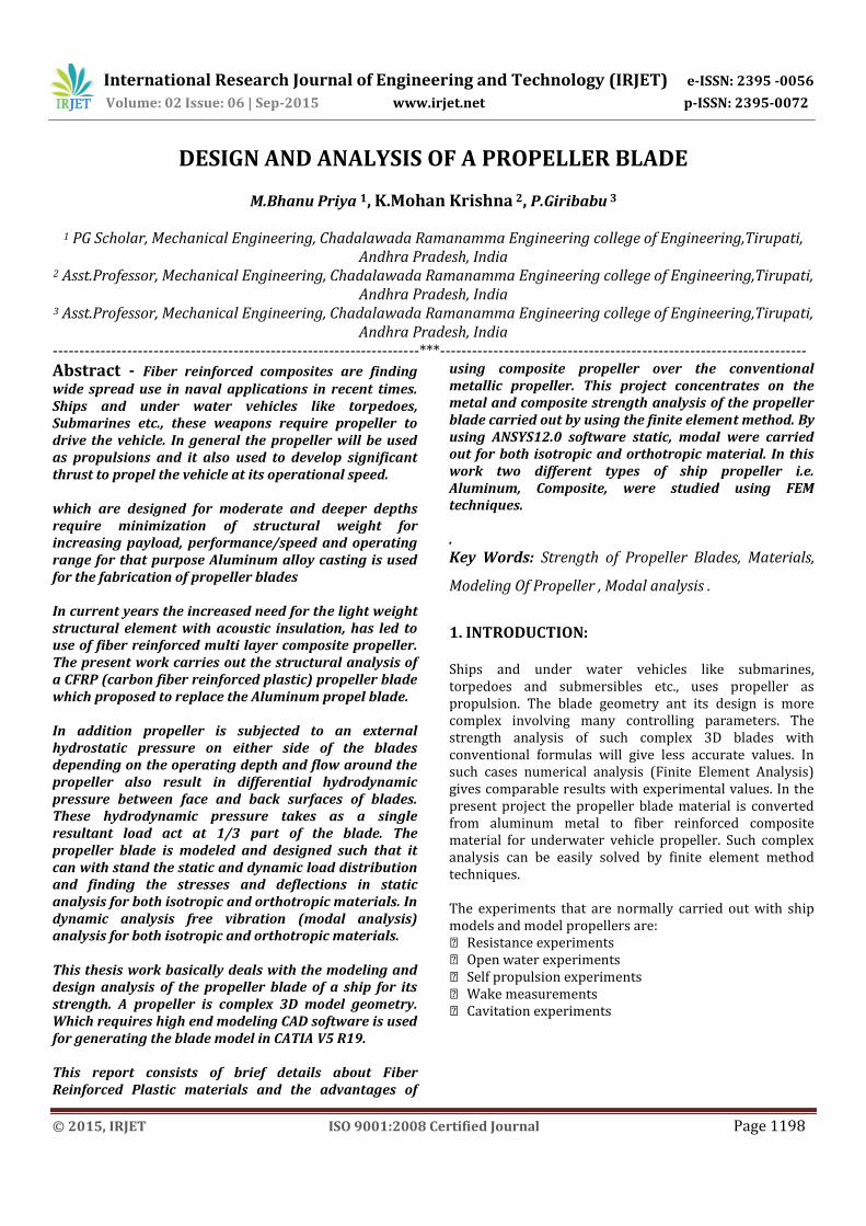
Normal stress in composite propeller in Y direction
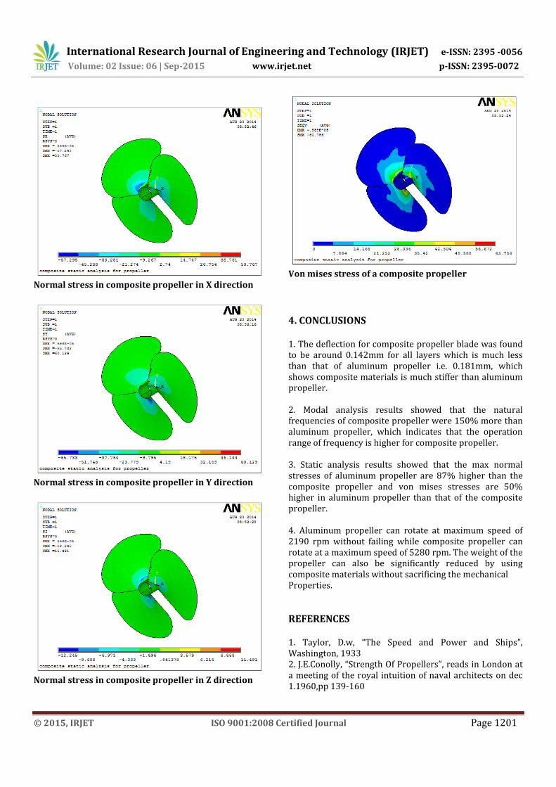
Normal stress in composite propeller in Z direction
Von mises stress of a composite propeller
4. CONCLUSIONS 1. The deflection for composite propeller blade was found to be around 0.142mm for all layers which is much less than that of aluminum propeller i.e. 0.181mm, which shows composite materials is much stiffer than aluminum propeller. 2. Modal analysis results showed that the natural frequencies of composite propeller were 150% more than aluminum propeller, which indicates that the operation range of frequency is higher for composite propeller. 3. Static analysis results showed that the max normal stresses of aluminum propeller are 87% higher than the composite propeller and von mises stresses are 50% higher in aluminum propeller than that of the composite propeller. 4. Aluminum propeller can rotate at maximum speed of 2190 rpm without failing while composite propeller can rotate at a maximum speed of 5280 rpm. The weight of the propeller can also be significantly reduced by using composite materials without sacrificing the mechanical Properties.
REFERENCES 1. Taylor, D.w, “The Speed and Power and Ships”, Washington, 1933 2. J.E.Conolly, “Strength Of Propellers”, reads in London at a meeting of the royal intuition of naval architects on dec 1.1960,pp 139-160

International Research Journal of Engineering and Technology (IRJET) e-ISSN: 2395 -0056
Volume: 02 Issue: 06 | Sep-2015 www.irjet.net p-ISSN: 2395-0072
© 2015, IRJET ISO 9001:2008 Certified Journal Page 1202
3. Terje sonntvedt, “Propeller Blade Stresses, Application Of Finite Element Methods” computers and structures, vol.4,pp193-204 4. Chang-sup lee, yong-jik kim,gun-do kim and in-sik nho. “Case Study On The Structural Failure Of Marine Propeller Blades” 5. M.jourdian, visitor and J.L.Armand. “Strength Of Propeller Blades-A Numerical Approach”, the socity of naval architects and marine engineers, may 24-25,1978,pp 20-1-21-3. 6. G.H.M.Beek, visitor, lips B.V.,Drunen. “Hub-Blade Interaction In Propeller Strength”, the socity of naval architects and marine enginers, may 24-25,1978,pp19-1-19-14 7. George W.Stickle and John L Crigler. “Propeller analysis from experimental data” report No.712, pp 147-164. 8. P.Castellini, C.Santolini. “Vibration Measurements On Blades Of A Naval Propeller Rotating In Water With Tracking Laser Vibromneter ”Dept. of mechanics, university of Ancona, pp43-54 9. W.J.Colclough and J.G.Russel. “The Development Of A Composite Propeller Blade With A CFRP Spar” aeronautical journal, Jan 1972, pp53-57 10. J.G.Russel “use of reinforced plastics in a composite propeller blade” plastics and polymers, Dec 1973 pp292-296