Embed Size (px)
Citation preview
Design and analysis of acoustically-driven 50 W thermoacousticrefrigerators
B G PRASHANTHA1,* , M S GOVINDE GOWDA2, S SEETHARAMU3 and
G S V L NARASIMHAM4
1Department of Industrial Engineering and Management, JSS Academy of Technical Education, Dr.
Vishnuvardhana Road, Bangalore 560 060, India2Vivekananda College of Engineering and Technology, Nehru Nagar, Puttur, Dakshina Kannada 574 203, India3Formerly Central Power Research Institute, Bangalore 560 080, India4Department of Mechanical Engineering, Indian Institute of Science, Bangalore 560 012, India
e-mail: [email protected]
MS received 22 September 2017; revised 24 January 2018; accepted 31 January 2018; published online 18 May 2018
Abstract. The design of loudspeaker-driven 50 W cooling power thermoacoustic refrigerators operating with
helium at 3% drive-ratio and 10 bar pressure for a temperature difference of 75 K using the linear thermoa-
coustic theory is discussed. The dimensional normalization technique to minimize the number of parameters
involved in the design process is discussed. The variation in the performance of the spiral stack-heat exchangers’
at 75% porosity as a function of the normalized stack length and center position is discussed. The resonator
optimization is discussed, and the optimized one-third-wavelength (tapered, small diameter tube and divergent
section with hemispherical end), and one-fourth-wavelength (tapered and divergent section with hemispherical
end) resonator designs show 41.3% and 30.8% improvements in the power density compared to the published 10
W designs, respectively. The back volume gas spring system for improving the performance of the loudspeaker
is discussed. The one-third-wavelength and one-fourth-wavelength resonator designs are validated using the
DeltaEC software, which predicts the cold heat exchanger temperature of - 3.4 �C at 0.882 COP, and - 4.3 �Cat 0.841 COP, respectively.
Keywords. Thermoacoustic; drive ratio; TSDH; TDH; driver; DeltaEC.
1. Introduction
The thermoacoustic refrigeration is the eco-friendly, simple
and upcoming technology uses no moving parts and
harmful refrigerants compared to the present domestic
Vapour Compression Refrigeration (VCR) units. The
thermoacoustic refrigerators can be made with the indige-
nous materials and hence costs less. Thermoacoustic
refrigerator works on the concepts of thermoacoustic effect
which converts sound energy into refrigeration effect.
Thermoacoustic refrigerator systems use loudspeakers to
drive themselves and hence these systems are known as
Acoustically-Driven Thermo-Acoustic Refrigerators
(ADTAR). The ADTAR can make use of the proportional
control systems to save the electrical energy input
depending on the cooling load. Proportional control system
improves overall efficiency by rapid cooling at lower COP
and avoiding heat leak losses at higher COP. Whereas the
present VCR units use binary control system, it comes on
for a while to achieve the desired low temperature and then
switched off. The ADTAR systems develop temperature
difference across the porous material known as the stack.
The stack is made up of the spirally wound thin and low
thermal conductivity sheets over the PVC rod with the
nylon spacer (fishing line) to facilitate spiral pores along
the length of the stack [1, 2]. The porous stack can also be
made with other geometries like parallel plates, circular,
pin array, etc. [3, 4]. The stack pumps heat from its low
temperature end to the other hot end through the oscillating
high thermal conductivity gas in the porous stack. The gas
oscillates front and back by the acoustic sound wave gen-
erated by the loudspeaker. The high frequency oscillation
of the gas causes maximum compression and expansion at
the hot and cold end of the stack, respectively. The oscil-
lating gas forms the thin thermal conductivity layer along
the length of stack to facilitate heat pumping and causes
temperature difference across the stack. Hence the ther-
moacoustic refrigerator makes use of the hot and cold heat
exchangers placed on the hot and cold end of the stack,
respectively. The Cold Heat Exchanger (CHX) absorbs the
*For correspondence
1
Sådhanå (2018) 43:82 � Indian Academy of Sciences
https://doi.org/10.1007/s12046-018-0860-8Sadhana(0123456789().,-volV)FT3](0123456789().,-volV)
heat from the cold chamber through the secondary fluid
circulating in it and rejects to the surrounding cold gas for
heat pumping. The Hot Heat Exchanger (HHX) absorbs the
heat from the surrounding hot gas and rejects to the cooling
water circulating in it. Therefore to facilitate heat pumping
along the stack, it is necessary to install the stack-heat
exchangers’ assembly in the low thermal conductivity solid
resonator tube filled with the working gas. On the left end
of the resonator tube the loudspeaker is attached to generate
sound waves, and the other end is closed to form the
standing wave. The resonator tube can have the geometries
like TSDH, TDH, CDH and TSD designs as found in the
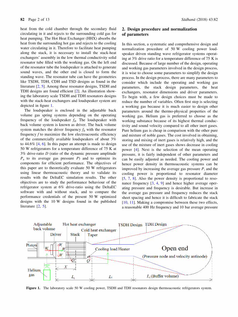
literature [2, 5]. Among these resonator designs, TSDH and
TDH designs are found efficient [2]. An illustration show-
ing the laboratory scale TSDH and TDH resonators designs
with the stack-heat exchangers and loudspeaker system are
depicted in figure 1.
The loudspeaker is enclosed in the adjustable back
volume gas spring systems depending on the operating
frequency of the loudspeaker fd. The loudspeaker with
back volume system is known as driver. The back volume
system matches the driver frequency fd with the resonator
frequency f to maximize the low electroacoustic efficiency
of the commercially available loudspeakers of about 3%
to 44.6% [4, 6]. In this paper an attempt is made to design
50 W refrigerators for a temperature difference of 75 K at
3% drive-ratio D (ratio of the dynamic pressure amplitude
Pa to its average gas pressure P) and to optimize its
components for efficient performance. The objectives of
this paper are to theoretically evaluate 50 W refrigerators
using linear thermoacoustic theory and to validate its
results with the DeltaEC simulation results. The other
objectives are to study the performance behaviour of the
refrigerator system at 6% drive-ratio using the DeltaEC
software with and without stack, and to compare the
performance credentials of the present 50 W optimized
designs with the 10 W designs found in the published
literature [2, 5].
2. Design procedure and normalizationof parameters
In this section, a systematic and comprehensive design and
normalization procedure of 50 W cooling power loud-
speaker driven standing wave refrigerator systems operat-
ing at 3% drive ratio for a temperature difference of 75 K is
discussed. Because of large number of the design, operating
and working gas parameters involved in the design process,
it is wise to choose some parameters to simplify the design
process. In the design process, there are many parameters to
consider which include the operating and working gas
parameters, the stack design parameters, the heat
exchangers, resonator dimensions and driver parameters.
To begin with, a few design choices must be made to
reduce the number of variables. Often first step is selecting
a working gas because it is much easier to design other
parameters around the thermo-physical properties of the
working gas. Helium gas is preferred to choose as the
working substance because of its highest thermal conduc-
tivity and sound velocity compared to all other inert gases.
Pure helium gas is cheap in comparison with the other pure
and mixture of noble gases. The cost involved in obtaining,
storing and mixing of inert gases is relatively high, and the
use of the mixture of inert gases shows decrease in cooling
power [4]. Next is the selection of the mean operating
pressure, it is fairly independent of other parameters and
can be easily adjusted as needed. The cooling power and
hence power density in thermoacoustic systems can be
improved by increasing the average gas pressure P, and the
cooling power is proportional to resonator diameter
[5, 7, 8]. Also the power density is proportional to reso-
nance frequency [3, 4, 9] and hence higher average oper-
ating pressure and frequency is desirable. But increase in
the average gas pressure and frequency reduces the stack
sheet spacing and hence it is difficult to fabricate the stack
[10, 11]. Making a compromise between these two effects,
a reasonable 400 Hz frequency and 10 bar average pressure
Figure 1. The laboratory scale 50 W cooling power, TSDH and TDH resonators design thermoacoustic refrigerators system.
82 Page 2 of 13 Sådhanå (2018) 43:82
is chosen. For the purpose of avoiding severe nonlinearities
in the system and to obtain better modelling accuracy for
the standing wave refrigerators, it is suggested that the
drive-ratio, D must be B 3%. Such systems are generally
termed as low amplitude thermoacoustic systems [12].
Even after these preliminary choices, the stack is an
appropriate place to begin, as it is often difficult to machine
and construct a stack to meet predetermined specifications.
Once the stack material and geometry is chosen, the CHX,
HHX and the resonator system can be designed accord-
ingly. Finally, an appropriate loudspeaker can be chosen.
The popular dimensional normalization technique is used
to reduce the total number of parameters involved in design
process [13]. The design of a refrigerator system depends
on large number of dependent parameters, which can be
grouped under stack geometrical parameters, material
specific parameters and design requirement parameters
[2, 14]. The stack geometrical parameters are: stack posi-
tion and length, plate spacing and thickness, and cross
sectional area. The working gas and stack material specific
parameters include: thermo-physical properties of the
working gas and the stack density, specific heat and thermal
conductivity. The design requirement parameters are given
by: resonance frequency, average gas pressure, dynamic
pressure amplitude of the working gas, mean temperature,
the required temperature gradient across the stack heat
exchangers system and the required cooling power. It is
laborious to deal with the twenty two dependent parameters
as listed in table 1. Using parameters normalization tech-
nique, the total number of parameters involved in the
design process is reduced to eleven independent parameters
(table 1). The normalized thermal and viscous penetration
depths for most of the linear thermoacoustic models are
found to be in the range of 0.5–1 and 0.5r2 to r2,
respectively [15]. The porosity (also called as blockage
ratio) e of the stack-heat exchangers system recommended
in the literature for the linear thermoacoustic model was set
equal to 0.75 [4].
3. Design and optimization of spiral stack-heatexchangers system, and resonator system
In this section, the design and optimization of spiral stack-
heat exchangers system, and resonator systems of 50 W
refrigerators at 3% drive-ratio for a temperature difference
Table 1. Dependent and independent design parameters of thermoacoustic refrigerator having 50 W cooling power.
Dependent parameters Independent (normalized) parameters
1. Temperature gradient across stack: hx 1. Normalized temperature gradient: hn ¼ hxTmg
2. Mean temperature of gas: Tmg
3. Isobaric specific heat of helium gas: Cph 2. Index of compression: c ¼ Cph
Cvh
4. Isochoric specific heat of helium gas: Cvh 3. Normalized viscous penetration depth:
dvn ¼ dvy
5. Sound velocity:
u ¼ffiffiffiffiffiffiffiffiffiffiffiffiffiffiffiffiffiffiffiffiffiffiffiffiffiffiffiffi
TmgCph c� 1ð Þp
4. Normalized thermal penetration depth:
dkn ¼ dky
6. Resonator operating frequency: f5. Prandtl number: r ¼ dv
dk
� �2
¼ lCph
kh
7. Angular frequency: x = 2pf rads-1 6. Porosity or Blockage ratio: e ¼ yyþlð Þ
8. Wave number: k 7. Drive-ratio: D ¼ Pa
P
9. Average gas pressure: P 8. Normalized stack length: l4n = kl410. Viscosity of helium: l 9. Normalized stack centre position: Xn = kX
11. Density of helium: q 10. Normalized cooling power of the stack: Qns ¼ QPuAð Þ
12. Viscous penetration depth of helium:
dv ¼ffiffiffiffiffi
2lqx
q
¼ffiffiffiffiffiffiffiffiffiffi
2lq 2pfð Þ
q
11. Normalized acoustic power of the stack: Wns ¼ Ws
PuAð Þ
13. Thermal conductivity of helium: kh
14. Thermal penetration depth of helium: dk ¼ffiffiffiffiffiffiffiffiffiffiffiffiffiffiffi
2khqCph 2pfð Þ
q
15. Half stack sheet spacing: y = 2dk
16. Half stack sheet thickness: l
17. Dynamic pressure amplitude: Pa
18. Stack length: l419. Stack center position: X
20. Cooling power: Q
21. Cross-sectional area of stack: A
22. Acoustic power consumed by the stack: Ws
Sådhanå (2018) 43:82 Page 3 of 13 82
of 75 K are discussed. The most important term which
decides performance of the refrigerator system is the crit-
ical temperature difference across the stack is also dis-
cussed. The results of spiral stack performance as a
function of the normalized stack center position, and stack
length, and the variation of design and performance
parameters as a function of the normalized stack center
position, and length are also notified and detailed. And the
design and analysis of the TSDH and TDH resonator
designs are discussed.
3.1 Design and optimization of a 50 W spiral
stack-heat exchangers system
The stack is considered as the heart in the stack-based
thermoacoustic refrigerators because the performance of
the whole refrigerator greatly depends on the stack itself.
The stack pumps heat from its cold end to hot end through
the pores of the spirally wound stack sheet material. The
rate of stack heat pumping depends on the thermal con-
ductivity and the velocity of the oscillating gas. The stack
sheet material conducts the heat in the direction opposite to
the stack heat pumping (from hot end of the stack to cold
end), which decreases the performance of the stack [3, 4].
Hence it is a wise choice to select the stack sheet material
with low thermal conductivity, and the heat capacity much
greater than the heat capacity of working gas for its long
life. Therefore the locally available Mylar sheet meets the
design requirements. The stack can have different geometry
viz. spiral pores, parallel plates, circular pores, pin arrays,
triangular pores, etc. In this research work, the thin spiral
pores stack geometry is chosen since it is easy to manu-
facture and takes less time compared to other geometries.
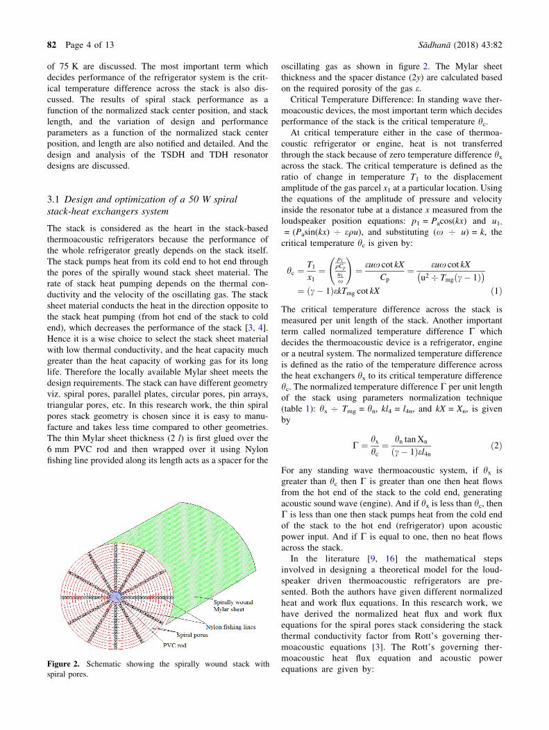
The thin Mylar sheet thickness (2 l) is first glued over the
6 mm PVC rod and then wrapped over it using Nylon
fishing line provided along its length acts as a spacer for the
oscillating gas as shown in figure 2. The Mylar sheet
thickness and the spacer distance (2y) are calculated based
on the required porosity of the gas e.Critical Temperature Difference: In standing wave ther-
moacoustic devices, the most important term which decides
performance of the stack is the critical temperature hc.
At critical temperature either in the case of thermoa-
coustic refrigerator or engine, heat is not transferred
through the stack because of zero temperature difference hx
across the stack. The critical temperature is defined as the
ratio of change in temperature T1 to the displacement
amplitude of the gas parcel x1 at a particular location. Using
the equations of the amplitude of pressure and velocity
inside the resonator tube at a distance x measured from the
loudspeaker position equations: p1 = Pacos(kx) and u1-
= (Pasin(kx) 7 equ), and substituting (x 7 u) = k, the
critical temperature hc is given by:
hc ¼T1
x1
¼p1
qCp
u1
x
!
¼ eux cot kX
Cp
¼ eux cot kX
u2 � Tmg c� 1ð Þ� �
¼ c� 1ð ÞekTmg cot kX ð1Þ
The critical temperature difference across the stack is
measured per unit length of the stack. Another important
term called normalized temperature difference C which
decides the thermoacoustic device is a refrigerator, engine
or a neutral system. The normalized temperature difference
is defined as the ratio of the temperature difference across
the heat exchangers hx to its critical temperature difference
hc. The normalized temperature difference C per unit length
of the stack using parameters normalization technique
(table 1): hx 7 Tmg = hn, kl4 = l4n, and kX = Xn, is given
by
C ¼ hx
hc
¼ hn tan Xn
c� 1ð Þel4n
ð2Þ
For any standing wave thermoacoustic system, if hx is
greater than hc then C is greater than one then heat flows
from the hot end of the stack to the cold end, generating
acoustic sound wave (engine). And if hx is less than hc, then
C is less than one then stack pumps heat from the cold end
of the stack to the hot end (refrigerator) upon acoustic
power input. And if C is equal to one, then no heat flows
across the stack.
In the literature [9, 16] the mathematical steps
involved in designing a theoretical model for the loud-
speaker driven thermoacoustic refrigerators are pre-
sented. Both the authors have given different normalized
heat and work flux equations. In this research work, we
have derived the normalized heat flux and work flux
equations for the spiral pores stack considering the stack
thermal conductivity factor from Rott’s governing ther-
moacoustic equations [3]. The Rott’s governing ther-
moacoustic heat flux equation and acoustic power
equations are given by:Figure 2. Schematic showing the spirally wound stack with
spiral pores.
82 Page 4 of 13 Sådhanå (2018) 43:82
Q ¼ �Pdk
4
Tmbp1u1
1 þ �sð Þ 1 þ rð ÞK C1 þ
ffiffiffi
rp
þ rþ r�s
1 þffiffiffi
rp
�
� 1 þffiffiffi
rp
� dv
y
�
�P yK þ lKsð Þ Tm
l4
ð3Þ
The terms in the right hand side of the above equation
represents the thermoacoustic heat conduction through the
working gas and stack material.
W ¼ Pl3
4
dk � � 1ð Þxp21
qu2 1 þ �sð ÞC
1 þffiffiffi
rp
ð ÞK� 1
�
� dvxqu21
K
�
ð4Þ
Here K is the heat energy conduction correction factor for
the given operating gas which is defined as
K ¼ 1 � dvyþ 0:5
d2v
y2ð5Þ
The first and second terms in Eq. (4) are referred to as the
thermal and viscous relaxation dissipation terms for the
operating gas, respectively. For an ideal stack, the stack
thermal conductivity Ks and heat capacity ratio �s (which is
the ratio of the heat capacity of the working gas to the heat
capacity of the stack material) are assumed to be zero.
Assuming the working gas (helium) behaves like an ideal
gas such that the product Tmb is equal to one. Substituting
the equations for u, e, r, dv and dk given in table 1, and
P = A/(y ? l), p1 = Pacos(kx) and u1 = Pasin(kx)/equ and
using the definitions of the normalized parameters into
Eqs. (3) and (4). Dividing Eqs. (3) and (4) by the product
(PuA), and taking the hydraulic radius equal to half-stack
spacing (rh = y), then the normalized heat power output
equation Qn-s and work power input equation Wn-s with
circular pores stack are given by:
Qn�s ¼�dknD
2 sin 2Xn�sð Þ8c 1 þ rð ÞK
� C1 þ
ffiffiffi
rp
þ r1 þ
ffiffiffi
rp � 1 þ
ffiffiffi
rp
�ffiffiffi
rp
dkn� �
�
� eK1:
ð6Þ
The term K1 in Eq. (6) is the normalized helium gas thermal
conductivity factor which is given by:
K1 ¼ KhTmg
Pul3ð7Þ
and
Wn�s ¼dknl3nD
2
4cc� 1ð Þecos2 Xn�sð Þ C
1 þffiffiffi
rp
ð ÞK� 1
� �
�ffiffiffi
rp
sin2ðXn�sÞeK
ð8Þ
Using the normalized Eqs. (6)–(8), the stack COP for the
refrigerator system is given by:
COPs ¼Qn�s
Wn�s
ð9Þ
Let d1 be the diameter of the large resonator tube neglecting
stack holder thickness which is much smaller than d1. The
large resonator tube holds the stack-heat exchangers sys-
tem. The ‘‘large resonator tube diameter’’ also known as
‘‘stack diameter’’ d1 is found from the stack cross-section
A. The stack cross-section A is found from the design
optimization of the spiral stack.
Determination of the stack cross-section A: Using data
given in table 2 in Eqs. (6)–(8), the stack COP is deter-
mined using Eq. (9). The spiral stack performance COPs
versus various normalized stack length l4n and center
position Xn-s are given in table 3.
The selection of the optimal stack length l4 and centre
position X helps the designer in providing sufficient space
to accommodate the loudspeaker, pressure and temperature
sensors during fabrication. The selection of the optimum
stack length and center position is decided based on the
performance of the stack (COPs) itself. Highest perfor-
mance of the stack consumes lowest acoustic power input
and vice-versa. Improvement in the stack performance
improves cooling power and hence the performance of the
whole refrigerator system. Based on the above discussion it
is decided to select the best normalized stack length (l4n)
and centre position (Xn) as 0.2. The optimized stack COP at
this condition is found to be 1.598. Substituting the value of
k (wave number) from table 2 in the normalized stack
length and center position equations (table 1), the stack
length and centre position is found to be 76 mm. It is as
good as keeping the hot end of the stack at a distance
38 mm away from the loudspeaker position. Substituting
the known data in Eq. (6), the normalized cooling power
Qn-s is given by 6.946 9 10-6. The stack cross-section A is
calculated by substituting the given data (table 2) in the
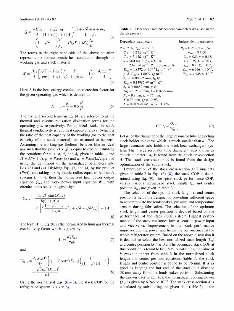
Table 2. Dependent and independent parameters data used in the
design process.
Dependent parameters Independent parameters
h = 75 K, Tmg = 266 K,
Cph = 5.2 kJ kg-1 K-1,
Cvh = 3.1 kJ kg-1 K-1,
u = 960 ms-1, f = 400 Hz,
k = 2.62 rad m-1, P = 10 bar, l @
Tmg = 1.8372 9 10-5 kg m-1 s-1,
q @ Tmg = 1.8097 kg m-3,
dv = 0.089882 mm, kh @
Tmg = 0.13985 W m-1 K-1,
dk = 0.10882 mm, y @
2dk = 0.2176 mm, l = 0.0725 mm,
Pa = 0.3 bar, l4 = 76 mm,
X = 76 mm, Q = 10 W,
A = 0.007498 m2, Ws = 31.3 W
hn = 0.282, c = 1.67,
dvn = 0.4131,
dkn = 0.5, r = 0.68,
e = 0.75, D = 0.03,
l4n = 0.2, Xn = 0.2,
Qns = 6.946 9 10-6,
Wns = 4.348 9 10-6
Sådhanå (2018) 43:82 Page 5 of 13 82
equation Qn-s = Q 7 (PuA). And using the stack cross-
section A, the stack diameter d1 is found to be 98 mm.
Similarly, the normalized acoustic power (Wn-s)
4.348 9 10-6 is found using Eq. (8). The acoustic power
consumed by the stack Ws for pumping 50 W of heat load is
calculated using the equation Wn-s = Ws 7 (PuA) is found
to be 31.3 W (table 4).
Heat Exchangers Design: Heat exchangers namely the
CHX and HHX are placed in close contact with the cold
end and hot end of the stack, respectively as shown in
figure 1. The CHX absorb the heat from the cold chamber
(source) to produce refrigeration effect and the same heat is
pumped to the HHX through the stack upon the acoustic
power W supplied by the loudspeaker into the resonator
system. The circulating cooling water removes the heat
from the HHX to the atmosphere (sink). The cold and hot
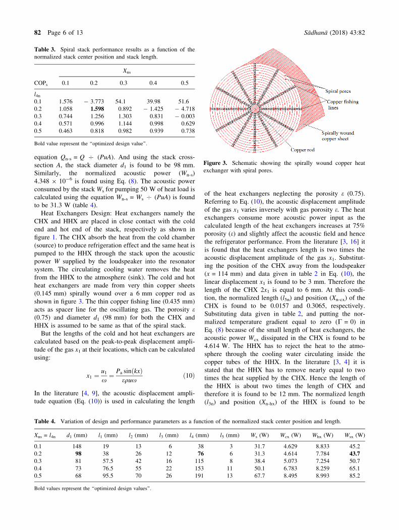
heat exchangers are made from very thin copper sheets
(0.145 mm) spirally wound over a 6 mm copper rod as
shown in figure 3. The thin copper fishing line (0.435 mm)
acts as spacer line for the oscillating gas. The porosity e(0.75) and diameter d1 (98 mm) for both the CHX and
HHX is assumed to be same as that of the spiral stack.
But the lengths of the cold and hot heat exchangers are
calculated based on the peak-to-peak displacement ampli-
tude of the gas x1 at their locations, which can be calculated
using:
x1 ¼ u1
x¼ Pa sin kxð Þ
equxð10Þ
In the literature [4, 9], the acoustic displacement ampli-
tude equation (Eq. (10)) is used in calculating the length
of the heat exchangers neglecting the porosity e (0.75).
Referring to Eq. (10), the acoustic displacement amplitude
of the gas x1 varies inversely with gas porosity e. The heat
exchangers consume more acoustic power input as the
calculated length of the heat exchangers increases at 75%
porosity (e) and slightly affect the acoustic field and hence
the refrigerator performance. From the literature [3, 16] it
is found that the heat exchangers length is two times the
acoustic displacement amplitude of the gas x1. Substitut-
ing the position of the CHX away from the loudspeaker
(x = 114 mm) and data given in table 2 in Eq. (10), the
linear displacement x1 is found to be 3 mm. Therefore the
length of the CHX 2x1 is equal to 6 mm. At this condi-
tion, the normalized length (l5n) and position (Xn-cx) of the
CHX is found to be 0.0157 and 0.3065, respectively.
Substituting data given in table 2, and putting the nor-
malized temperature gradient equal to zero (C = 0) in
Eq. (8) because of the small length of heat exchangers, the
acoustic power Wcx dissipated in the CHX is found to be
4.614 W. The HHX has to reject the heat to the atmo-
sphere through the cooling water circulating inside the
copper tubes of the HHX. In the literature [3, 4] it is
stated that the HHX has to remove nearly equal to two
times the heat supplied by the CHX. Hence the length of
the HHX is about two times the length of CHX and
therefore it is found to be 12 mm. The normalized length
(l3n) and position (Xn-hx) of the HHX is found to be
Table 3. Spiral stack performance results as a function of the
normalized stack center position and stack length.
COPs
Xns
0.1 0.2 0.3 0.4 0.5
l4n
0.1 1.576 - 3.773 54.1 39.98 51.6
0.2 1.058 1.598 0.892 - 1.425 - 4.718
0.3 0.744 1.256 1.303 0.831 - 0.003
0.4 0.571 0.996 1.144 0.998 0.629
0.5 0.463 0.818 0.982 0.939 0.738
Bold value represent the ‘‘optimized design value’’.
Figure 3. Schematic showing the spirally wound copper heat
exchanger with spiral pores.
Table 4. Variation of design and performance parameters as a function of the normalized stack center position and length.
Xns = l4n d1 (mm) l1 (mm) l2 (mm) l3 (mm) l4 (mm) l5 (mm) Ws (W) Wcx (W) Whx (W) Wsx (W)
0.1 148 19 13 6 38 3 31.7 4.629 8.833 45.2
0.2 98 38 26 12 76 6 31.3 4.614 7.784 43.70.3 81 57.5 42 16 115 8 38.4 5.073 7.254 50.7
0.4 73 76.5 55 22 153 11 50.1 6.783 8.259 65.1
0.5 68 95.5 70 26 191 13 67.7 8.495 8.993 85.2
Bold values represent the ‘‘optimized design values’’.
82 Page 6 of 13 Sådhanå (2018) 43:82
0.0314 and 0.0838, respectively. Similar to CHX, the
acoustic power Whx dissipated in the HHX is calculated
using Eq. (8) is found to be 7.784 W. In table 4 it is found
that the total acoustic power consumed in the stack-heat
exchangers system (Wsx) is lowest 43.7 W at Xns = l4n-
= 0.2, and hence the selection of the stack length and
centre positions at 76 mm is justified.
3.2 Design and analysis of resonator system
The resonator is designed such that the length, mass, losses
and shape are at the optimum level. The resonator tube
should be strong enough to sustain pressure greater than or
equal to 10 bar and has good surface finish to reduce the
heat dissipation losses. The resonator must be made from
the low thermal conductivity material to minimize the heat
dissipation losses [17, 18]. The performance of the refrig-
erator system improves with decrease in resonator heat
dissipation losses. Also the ambient heat may leak into the
CHX section of the resonator tube with the normal insu-
lation. Hence it is advisable to keep the resonator system
under vacuum or to provide multi-layered-super-insulation
to attenuate heat leak losses. From the literature [3, 4, 17], it
is learnt that one-fourth-wavelength resonator tube losses
are 50% lower than the half-wavelength resonator tube. The
total length of the one-fourth-wavelength resonator tube is
found by:
Lt ¼0:25u
fð11Þ
The one-fourth-wavelength resonator tube with the same
large diameter tube d1 throughout its length has resonator
losses. Therefore the attempts are made in this paper to
reduce the resonator losses by decreasing the cross-section
of the resonator tube right side to the CHX. The cross-
section right side to the CHX is roughly up to 75% of the
resonator length measured from the loudspeaker position
or which is approximately the middle portion of the res-
onator tube, is decreased to reduce the resonator losses.
Let d2 be the diameter of the small (reduced) tube. The
small length 20 mm taper is used to connect the large and
small diameter tubes. The total acoustic power loss as heat
load along the length of the small diameter tube d2 is
given by [17]:
W2 ¼d2
d1
cos kxAð Þcos kx1
A
� �
!2
1þ c� 1ffiffiffi
rp
�
kx1B � kx1
A
� �
�
þ0:5 1� c� 1ffiffiffi
rp
�
sinð2kx1A
� �
� sin 2kx1B
� �
Þ
pd1dvuP2a
8cP
ð12Þ
where kxA is the normalized large diameter tube length and
kx1A is the normalized large diameter tube length at diam-
eter-ratio d2/d1 which is given by:
kx1A ¼ tan�1 d1
d2
� 2
tan kxAð Þ !
ð13Þ
In Eq. (12), the two subscripts ‘A’ and ‘B’ refers to the two
transition points. Subscript ‘A’ is for between d1 and d2 and
subscript ‘B’ is referred to the transition point between d2
and the buffer volume. The buffer volume is large and it
simulates an open end. The acoustic pressure attains max-
imum and the velocity is zero at the loudspeaker closed
end. The total acoustic power loss W2 as heat load along the
length of the small diameter tube d2 versus diameter ratio
d2/d1 is calculated using Eq. (12) as given in table 5.
The W2 losses in the small diameter tube d2 is minimum
at d2/d1 = 0.8. At this diameter ratio, the thermal and vis-
cous losses in the small diameter tube are minimal. The
diameter-ratio d2/d1 = 0.8 is used in this work while
designing a 50 W refrigerator at 3% drive-ratio for the
temperature difference of 75 K. Let L1 be the length of the
large tube d1 and x is the position away from the loud-
speaker. At the interface between d1 and d2 (at x = L1), the
pressure and velocity distributions should be continuous.
Let Z1 and Z2 are the acoustic impedances in d1 and d2,
respectively and are made equal at x = L1 as given below.
Z1 ¼ P1
A1u1
¼ Z2 ¼ P2
A2u2
ð14Þ
Where P1 ¼ Pa cos kL1ð Þ, u1 ¼ Pa sin kL1ð Þ=qu, P2 ¼Pa sin kL2ð Þ and u2 ¼ Pa cos kL2ð Þ=qu, L2 is the length of d2
and by substitution:
cot kL1ð Þ ¼ d1
d2
� 2
tan kL2ð Þ ð15Þ
Using data given in table 2 in Eq. (11), the total length of
the one-fourth-wavelength resonator tube (Lt) is found to be
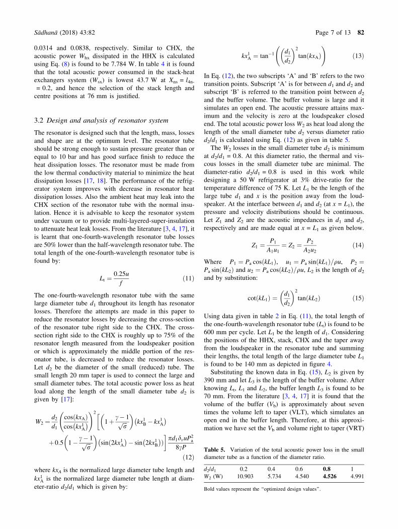
600 mm per cycle. Let L1 be the length of d1. Considering
the positions of the HHX, stack, CHX and the taper away
from the loudspeaker in the resonator tube and summing
their lengths, the total length of the large diameter tube L1
is found to be 140 mm as depicted in figure 4.
Substituting the known data in Eq. (15), L2 is given by
390 mm and let L3 is the length of the buffer volume. After
knowing Lt, L1 and L2, the buffer length L3 is found to be
70 mm. From the literature [3, 4, 17] it is found that the
volume of the buffer (Vb) is approximately about seven
times the volume left to taper (VLT), which simulates an
open end in the buffer length. Therefore, at this approxi-
mation we have set the Vb and volume right to taper (VRT)
Table 5. Variation of the total acoustic power loss in the small
diameter tube as a function of the diameter ratio.
d2/d1 0.2 0.4 0.6 0.8 1
W2 (W) 10.903 5.734 4.540 4.526 4.991
Bold values represent the ‘‘optimized design values’’.
Sådhanå (2018) 43:82 Page 7 of 13 82
for the 50 W resonator tube (figure 4) are equal to 4.85 L
and 6.73 L, respectively. At this condition, the diverging
angle h2 in the buffer length and total length Lt for the
optimized 50 W 0.33k-TSDH resonator design is found to
be 19.7o and 800 mm, respectively. Dividing Eq. (4) by Pl3(stack surface area), setting C ¼ 0, neglecting the stack
plate heat capacity-ratio �s, and considering the half-stack
spacing y � dk, we get an equation for the acoustic power
loss per unit surface area of the resonator tube w, which is
given by:
w ¼ 0:25qhu21dvxþ 0:25
p21 c� 1ð Þdkx
qhu2ð16Þ
The first and second terms in the right-hand side of Eq. (16)
represents the viscous and thermal losses in the resonator
system. The pressure p1 and velocity u1 in Eq. (16) are cal-
culated at the mean centre positions of the components in the
resonator tube measured from the loudspeaker position. For
example: the pressure p1 and velocity u1 at the mean centre
position of the duct between the loudspeaker and HHX, and
similarly at the mean centre positions of the HHX, stack,
CHX, taper, small diameter tube length, divergent section,
and at the hemisphere. The acoustic power lost by each
resonator component (wrc) is obtained by multiplying
Eq. (16) by an individual component surface area. The total
resonator surface area At for the k/3-TSDH resonator design
(figure 4) is found to be 2810 cm2. The total acoustic power
lost as heat by the TSDH resonator design Wr is found to be
8.1 W, which is obtained by adding the calculated individual
resonator components acoustic power loss (wrc). The total
acoustic power utilized by the stack, heat exchangers and the
resonator system Wt, and the COP, COPC, and COPR for the
50 W refrigerators are obtained by:
Wt ¼ Ws þWcx þWhx þWr ð17Þ
COP ¼ Q
Wt
ð18Þ
COPC ¼ Tcx
Thx � Tcx
ð19Þ
COPR ¼ COP
COPCð20Þ
The total volume of the resonator Vt and hence the power
density Pv for the k/3-TSDH resonator design are found to
be 7.757 L and 6446 Wm-3 respectively as given in
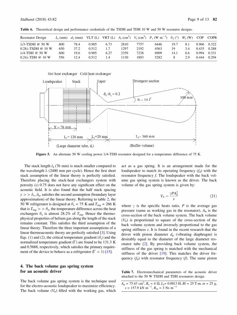
table 6. Further, the attempts are made to improve the
performance (COP) and power density (Pv) for the k/3-
TSDH resonator design by reducing At, VRT, and Vt.
Therefore an alternate, efficient and compact k/4-TDH
resonator design is proposed as shown in figure 5. The
alternate k/4-TDH resonator design is found to be efficient
compared to the k/3-TSDH resonator design (table 6). For
the k/4-TDH design, the diameter-ratio d2/d1 at the inter-
face between the taper and divergent sections is chosen to
be 0.2 and hence the throat diameter d2 is found to be
19.6 mm. The radius of the hemispherical end is chosen to
be 100 mm to minimize the resonator losses.
By restricting the total length of the resonator tube (Lt) to
600 mm to make the device compact, the diverging angle in
the buffer length h2 is found to be and 14.1o. The calculated
total resonator loss (Wr) for the k/4-TDH resonator design
is found to be 6.6 W, which is lower compared to the k/3-
TSDH resonator design (table 6). Therefore, the COP and
COPR for the k/4-TDH resonator design are comparatively
higher. The design and performance credentials of the
present 50 W TSDH and TDH resonator designs and the
published 10 W TSDH and TDH resonator designs [2] are
also given in table 6. The 50 W resonator designs are found
to be efficient compared to the 10 W resonator designs in
terms of power density and COP.
Figure 4. Optimized k/3-TSDH resonator design for a temperature difference of 75 K having 50 W cooling power.
82 Page 8 of 13 Sådhanå (2018) 43:82
The stack length l4 (76 mm) is much smaller compared to
the wavelength k (2400 mm per cycle). Hence the first short
stack assumption of the linear theory is perfectly satisfied.
Therefore placing the stack-heat exchangers system with
porosity (e) 0.75 does not have any significant effect on the
acoustic field. It is also found that the half stack spacing
y[[ dv, dk, satisfies the second assumption (boundary layer
approximation) of the linear theory. Referring to table 2, the
50 W refrigerator is designed at hx = 75 K and Tmg = 266 K
that is Tmg[[ hx, the temperature difference across the heat
exchangers hx is almost 28.2% of Tmg. Hence the thermo-
physical properties of helium gas along the length of the stack
remains constant. This satisfies the third assumption of the
linear theory. Therefore the three important assumptions of a
linear thermoacoustic theory are perfectly satisfied [3]. Using
Eqs. (1) and (2), the critical temperature gradient (hc) and the
normalized temperature gradient (U) are found to be 131.3 K
and 0.5688, respectively, which satisfies the primary require-
ment of the device to behave as a refrigerator (U\ 1) [15].
4. The back volume gas spring systemfor an acoustic driver
The back volume gas spring system is the technique used
for the electro-acoustic loudspeaker to maximize efficiency.
The back volume (Vb) filled with the working gas, which
act as a gas spring. It is an arrangement made for the
loudspeaker to match its operating frequency (fd) with the
resonator frequency f. The loudspeaker with the back vol-
ume gas spring system is known as the driver. The back
volume of the gas spring system is given by:
Vb ¼cPA2
b
sð21Þ
where c is the specific heats ratio, P is the average gas
pressure (same as working gas in the resonator), Ab is the
cross-section of the back volume system. The back volume
(Vb) is proportional to square of the cross-section of the
back volume system and inversely proportional to the gas
spring stiffness s. It is found in the recent research that the
driver with piston diameter dp (vibrating diaphragm) is
desirably equal to the diameter of the large diameter res-
onator tube [2]. By providing back volume system, the
stiffness of the gas spring is matched with the mechanical
stiffness of the driver [19]. This matches the driver fre-
quency (fd) with resonator frequency (f). The same piston
Table 6. Theoretical design and performance credentials of the TSDH and TDH 10 W and 50 W resonator designs.
Resonator Design Lt (mm) d2 (mm) VLT (L) VRT (L) At (cm2) Vt (cm3) Pv (W m-3) h2 (�) Wr (W) COP COPR
k/3-TSDH @ 50 W 800 78.4 0.905 6.73 2810 7757 6446 19.7 8.1 0.966 0.322
0.28k-TSDH @ 10 W 650 37.2 0.512 1.7 1297 2192 4563 19 3.4 0.435 0.288
k/4-TDH @ 50 W 600 19.6 0.905 6.27 2359 7238 6909 14.1 6.6 0.994 0.331
0.24k-TDH @ 10 W 556 12.4 0.512 1.4 1130 1893 5282 8 2.9 0.444 0.294
Figure 5. An alternate 50 W cooling power k/4-TDH resonator designed for a temperature difference of 75 K.
Table 7. Electromechanical parameters of the acoustic driver
attached to the 50 W TSDH and TDH resonators design.
Ap = 75.43 cm2, Re = 4 X, Le= 0.0013 H, Bl = 25 T-m, m = 25 g,
s = 157.9 kN m-1, Rm = 3 Ns m-1
Sådhanå (2018) 43:82 Page 9 of 13 82
diameter may be used in the back volume gas spring system
(db = dp) (figure 1). The electromechanical parameters of
the driver are given in table 7 and by substituting the
known values in Eq. (21) at 10 bar pressure, the back
volume Vb is found to be 602 cc. The design and opti-
mization procedure for the commercially available loud-
speaker can be found elsewhere [4, 6].
5. DeltaEC modelling results and analysis
The DeltaEC stands for design environment for low-am-
plitude thermoacoustic energy conversion is a modelling
and simulation software specially designed for thermoa-
coustic engines and refrigerators [15, 20]. The DeltaEC
uses computer programme that integrates the one-dimen-
sional wave equation, heat flow equation and acoustic
power flow equation in a gas or a liquid for the complex
geometry developed by the designer. It is used to simulate
the performance behaviour of the theoretically designed
thermoacoustic devices (engines or refrigerators). The
DeltaEC models can make use of the following sequence of
thermoacoustic segments: loudspeaker, ducts, HHX, CHX,
stack, cones, compliances, etc. All the thermoacoustic
segments are assumed to have insulation wrapped around
their side-wall boundaries by default and hence the HHX
has to reject the heat energy (Qr) input to the CHX as the
heating load (Q) and the electrical energy input to the
loudspeaker (We). The electrical energy input to loud-
speaker is the sum of acoustic energy input to the resonator
(W) and the heat energy loss during energy conversion. For
every thermoacoustic segment, the integration is done using
the segment local parameters such as the length, area, and
perimeter and global parameters such as the average gas
pressure, operating frequency of the refrigerator, initial
temperature of the working gas, and the volume velocity of
the oscillating gas. It assumes isothermal except in the stack
and stack duct segments. The user can set the guesses and
targets for the required segment parameters. It also uses
Reverse Polish Notation (RPN), a parenthesis-free algebra
encoding technique. The user can define RPN segments at
the end of the programme part to determine the required
output parameters. The user has to iteratively adjust the
guesses variables in the programme to satisfy the required
targets. The detailed explanation regarding the design of
thermoacoustic refrigerator using the DeltaEC software
with text files can be found elsewhere [8, 15]. By using the
data given in tables 2 and 7 and the resonator designs
shown in figures 4 and 5 are validated using DeltaEC
software. The thermo-physical properties of the best com-
ponent materials used in building the DeltaEC simulation
models are given in table 8. The DeltaEC simulation per-
formance results for the 50 W k/3-TSDH and k/4-TDH
resonator designs at 3% drive-ratio showing the importance
of stack in the resonator system are given in table 9. The no
stack refrigerators show better COP at higher CHX tem-
perature (Tcx) because of the fluid turbulence in the res-
onator system compared to the stack-based systems.
Therefore, the stack-based refrigerator systems are pre-
ferred for obtaining better CHX temperature at lower COP
(Table 9). The simulation results as a function of the
cooling power and drive-ratio for an alternate and efficient
k/4-TDH resonator design are given in table 10. From the
simulation results we can interpret that at lower cooling
power, the refrigerator shows lower COP and lower CHX
temperature, and vice-versa. The results also show that the
higher drive-ratio (6%) is better for achieving lowest CHX
temperature at lower COP compared to 3% drive-ratio but
operating the refrigerator with 6% drive-ratio depends on
the force factor (Bl) of the loudspeaker as discussed
Table 8. Thermo-physical properties of the refrigerator components materials (at P = 10 bar, Tmg = 266 K and f = 400 Hz) chosen in
the DeltaEC simulation modelling.
Component type Preferred solid material Density (kg m-3) C (J kg-1 K-1) k (Wm-1 K-1) d (m)
Stack Kapton 1422.4 968.2 0.186 1.0367e-05
Mylar 1353.5 984.2 0.155 9.6296e-06
Heat exchangers (CHX/HHX) Copper 9000 420 399.9 2.9016e-04
Resonators/driver Ideal/Celcor 2510 686.8 2.5 3.3972e-05
Stainless 7930.3 437.6 13.7 5.6070e-05
Table 9. DeltaEC simulation performance results at 3% drive-ratio of the k/3-TSDH and k/4-TDH resonator designs showing the
importance of stack in the resonator system.
Resonator design Tmg (K) f (Hz) We (W) gea (%) Qr (W) Tcx (oC) hx (K) COP COPR
k/3-TSDH (with stack) 286 463 83.1 81 133.1 - 3.4 31.4 0.882 0.294
k/3-TSDH (without stack) 303 483 42.7 52.4 92.7 30 - 2.0 2.744 0.915
k/4-TDH (with stack) 286 480 83.5 81.2 133.5 - 4.3 32.3 0.841 0.280
k/4-TDH (without stack) 303 493 42.4 52.2 92.4 29.9 - 1.9 2.667 0.889
82 Page 10 of 13 Sådhanå (2018) 43:82
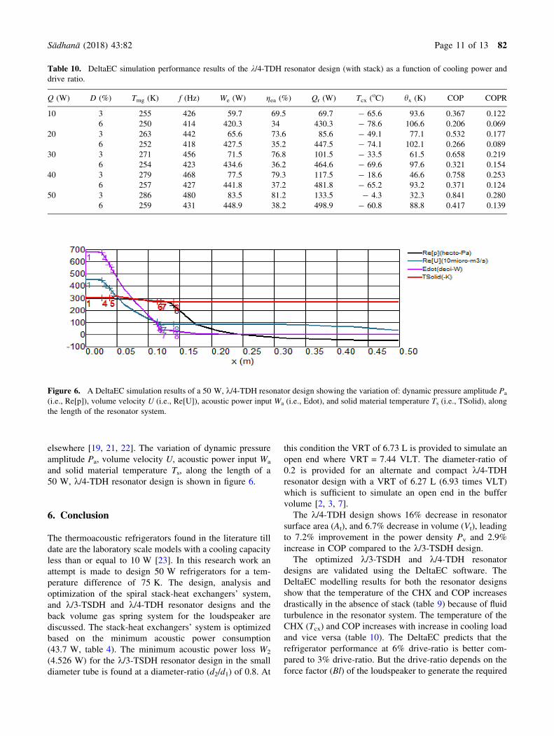
elsewhere [19, 21, 22]. The variation of dynamic pressure
amplitude Pa, volume velocity U, acoustic power input Wa
and solid material temperature Ts, along the length of a
50 W, k/4-TDH resonator design is shown in figure 6.
6. Conclusion
The thermoacoustic refrigerators found in the literature till
date are the laboratory scale models with a cooling capacity
less than or equal to 10 W [23]. In this research work an
attempt is made to design 50 W refrigerators for a tem-
perature difference of 75 K. The design, analysis and
optimization of the spiral stack-heat exchangers’ system,
and k/3-TSDH and k/4-TDH resonator designs and the
back volume gas spring system for the loudspeaker are
discussed. The stack-heat exchangers’ system is optimized
based on the minimum acoustic power consumption
(43.7 W, table 4). The minimum acoustic power loss W2
(4.526 W) for the k/3-TSDH resonator design in the small
diameter tube is found at a diameter-ratio (d2/d1) of 0.8. At
this condition the VRT of 6.73 L is provided to simulate an
open end where VRT = 7.44 VLT. The diameter-ratio of
0.2 is provided for an alternate and compact k/4-TDH
resonator design with a VRT of 6.27 L (6.93 times VLT)
which is sufficient to simulate an open end in the buffer
volume [2, 3, 7].
The k/4-TDH design shows 16% decrease in resonator
surface area (At), and 6.7% decrease in volume (Vt), leading
to 7.2% improvement in the power density Pv and 2.9%
increase in COP compared to the k/3-TSDH design.
The optimized k/3-TSDH and k/4-TDH resonator
designs are validated using the DeltaEC software. The
DeltaEC modelling results for both the resonator designs
show that the temperature of the CHX and COP increases
drastically in the absence of stack (table 9) because of fluid
turbulence in the resonator system. The temperature of the
CHX (Tcx) and COP increases with increase in cooling load
and vice versa (table 10). The DeltaEC predicts that the
refrigerator performance at 6% drive-ratio is better com-
pared to 3% drive-ratio. But the drive-ratio depends on the
force factor (Bl) of the loudspeaker to generate the required
Table 10. DeltaEC simulation performance results of the k/4-TDH resonator design (with stack) as a function of cooling power and
drive ratio.
Q (W) D (%) Tmg (K) f (Hz) We (W) gea (%) Qr (W) Tcx (oC) hx (K) COP COPR
10 3 255 426 59.7 69.5 69.7 - 65.6 93.6 0.367 0.122
6 250 414 420.3 34 430.3 - 78.6 106.6 0.206 0.069
20 3 263 442 65.6 73.6 85.6 - 49.1 77.1 0.532 0.177
6 252 418 427.5 35.2 447.5 - 74.1 102.1 0.266 0.089
30 3 271 456 71.5 76.8 101.5 - 33.5 61.5 0.658 0.219
6 254 423 434.6 36.2 464.6 - 69.6 97.6 0.321 0.154
40 3 279 468 77.5 79.3 117.5 - 18.6 46.6 0.758 0.253
6 257 427 441.8 37.2 481.8 - 65.2 93.2 0.371 0.124
50 3 286 480 83.5 81.2 133.5 - 4.3 32.3 0.841 0.280
6 259 431 448.9 38.2 498.9 - 60.8 88.8 0.417 0.139
Figure 6. A DeltaEC simulation results of a 50 W, k/4-TDH resonator design showing the variation of: dynamic pressure amplitude Pa
(i.e., Re[p]), volume velocity U (i.e., Re[U]), acoustic power input Wa (i.e., Edot), and solid material temperature Ts (i.e., TSolid), along
the length of the resonator system.
Sådhanå (2018) 43:82 Page 11 of 13 82
acoustic pressure amplitude Pa in the resonator system as
discussed elsewhere [2, 6].
The theoretically optimized and DeltaEC validated k/3-
TSDH and k/4-TDH resonator designs may be fabricated to
validate the real performance of the acoustically-driven
50 W thermoacoustic refrigerators similar to 10 W ther-
moacoustic refrigerators found in the published literature
[1] as the future scope.
Acknowledgements
This work was supported by JSSMVP Mysuru, Principal,
HOD (IEM) and all staff of the Department of Industrial
Engineering and Management, JSSATE Bengaluru.
Authors thank Bill Ward, John Clark, and Greg Swift,
Los Alamos National Laboratory, USA for developing
DeltaEC software and making it freely available for
research purpose.
List of symbolsA Cross-sectional area of the stack, m2
Ap Cross-sectional area of the loudspeaker piston, m2
At Total resonator surface area, cm2
Bl Force factor, NA-1 or T-m
CDH Convergent and divergent section with
hemispherical end
CHX Cold heat exchanger
COP Coefficient of performance
COPC Carnot’s coefficient of performance
COPR Coefficient of performance relative to Carnot’s
Cph Isobaric specific heat of helium gas, J kg-1 K-1
D Drive-ratio
d1 Large diameter tube, mm
d2 Small diameter tube or throat diameter, mm
f Resonator frequency, Hz
fd Driver frequency, Hz
HHX Hot heat exchanger
kh Thermal conductivity of helium gas, Wm-1 K-1
k Wave number, rad m-1
Le Driver electrical inductance, H
Lt Total resonator length, mm
l Half spiral stack sheet thickness, mm
l1 Distance between loudspeaker and hot end of the
stack, mm
l2 Distance between loudspeaker and hot heat
exchanger, mm
l3 Length of hot heat exchanger, mm
l4 Length of stack, mm
l5 Length of cold heat exchanger, mm
m Driver moving mass, kg
P Average gas pressure, bar
Pa Acoustic or dynamic pressure amplitude, bar
Pv Power density, Wm-3
p1 Acoustic pressure amplitude at a particular
location, Nm-2
Q Cooling power or cooling load at cold heat
exchanger, W
Qr Heat rejected by hot heat exchanger, W
Re Driver electrical resistance, XRm Driver mechanical resistance, Nsm-1
s Spring stiffness, kN m-1
TDH Taper and divergent section with hemispherical
end
TSD Taper and small diameter tube with divergent end
TSDH Taper, small diameter tube and divergent section
with hemispherical end
Tcx Temperature of the cold heat exchanger, K
Thx Temperature of the hot heat exchanger, K
Tmg Mean temperature of gas across heat exchangers,
K
u Velocity of sound, ms-1
u1 Velocity amplitude at a particular location,
ms-1
Vb Back volume of the loudspeaker, cc
Wa Acoustic power input to resonator system, W
We Electrical power input to loudspeaker, W
Wcx Acoustic power dissipated in the cold heat
exchanger, W
Whx Acoustic power dissipated in the hot heat
exchanger, W
Wsx Acoustic power dissipated in the stack-heat
exchangers system, W
W2 Total acoustic power loss in the small diameter
tube, W
X Stack center position, mm
x Position along sound propagation in the resonator
tube, mm
y Half spiral stack sheet spacing, mm
gea Electroacoustic efficiency of the loudspeaker, %
k Wavelength, mm
lh Dynamic viscosity of helium gas, kg m-1 s-1
hx Temperature difference across the hot and cold
heat exchangers, K
hc Critical temperature difference across the stack
length, K
h2 Diverging angle in the buffer volume, degree
dk Thermal penetration depth, mm
dv Viscous penetration depth, mm
e Porosity of the stack
c Ratio of specific heats
b Thermal volumetric expansion coefficient, K-1
C Normalized temperature difference
P Perimeter of the stack-heat exchangers system,
mm
K Helium gas conduction correction factor
r Prandtl number
qh Density of helium gas, kg m-3
82 Page 12 of 13 Sådhanå (2018) 43:82
References
[1] Prashantha B G, Govinde Gowda M S, Seetharamu S and G S
V L Narasimham 2017 Design construction and performance
of 10 W thermoacoustic refrigerators. Int. J. Air-Cond.
Refrig. 25(3): 1750023. https://doi.org/10.1142/s2010132
517500237
[2] Prashantha B G, Govinde Gowda M S, Seetharamu S and G S
V L Narasimham 2017 Design and comparative analysis of
thermoacoustic refrigerators. Int. J. Air-Cond. Refrig. 25(1):
1750002. https://doi.org/10.1142/s201013251750002x
[3] Swift G W 1988 Thermoacoustic engines. J. Acoust. Soc.
Am. 84(4): 1145–1180
[4] Tijani M E H 2001 Loudspeaker-Driven Thermo-Acoustic
Refrigeration. Ph.D. Thesis, Eindhoven University of
Technology.
[5] Prashantha B G, Govinde Gowda M S, Seetharamu S and G S
V L Narasimham 2013 Theoretical evaluation of 10-W
cooling power thermoacoustic refrigerator. Heat Transf.
Asian Res. J. https://doi.org/10.1002/htj.21094
[6] Prashantha B G, Govinde Gowda M S, Seetharamu S and G S
V L Narasimham 2013 Theoretical evaluation of loudspeaker
for a 10-W cooling power thermoacoustic refrigerator. Int.
J. Air-Cond. Refrig. 21(4): 1350027. https://doi.org/10.1142/
s2010132513500272
[7] Prashantha B G, Govinde Gowda M S, Seetharamu S and G S
V L Narasimham 2013 Design and analysis of thermoa-
coustic refrigerator. Int. J. Air-Cond. Refrig. 21(1): 1350001.
https://doi.org/10.1142/s2010132513500016
[8] Prashantha B G, Govinde Gowda M S, Seetharamu S and G S
V L Narasimham 2013 Effect of mean operating pressure on
the performance of stack-based thermoacoustic refrigerator.
Int. J. Therm. Environ. Eng. 5(1): 83–89, https://doi.org/10.
5383/ijtee.05.01.009
[9] Tijani M E H, Zeegers J C H and de Waele A T A M 2002
Design of thermoacoustic refrigerators. Cryogenics 42:
49–57
[10] Tijani M E H, Zeegers J C H and de Waele A T A M 2002
The optimal stack spacing for thermoacoustic refrigeration.
J. Acoust. Soc. Am. 112(1): 128–133
[11] Tijani M E H, Zeegers J C H and de Waele A T A M 2002
Construction and performance of a thermoacoustic refriger-
ator. Cryogenics 42: 59–66
[12] Poese M E and Garrett S L 2000 Performance measurements
on a thermoacoustic refrigerator driven at high amplitudes. J.
Acoust. Soc. Am. 107(5): 2480–2486
[13] Olson J R and Swift G W 1994 Similitude in thermoacoustic.
J. Acoust. Soc. Am. 95(3): 1405–1412
[14] Prashantha B G, Govinde Gowda M S, Seetharamu S and G
S V L Narasimham 2016 Design analysis of thermoacoustic
refrigerator using air and helium as working substances. Int.
J. Therm. Environ. Eng. 13(2): 113–120. https://doi.org/10.
5383/ijtee.13.02.006
[15] Swift G W 2002 Thermoacoustics: a unifying perspective of
some engines and refrigerators. Acoustical Society of
America, Melville
[16] Wetzel M and Herman C 1997 Design optimization of
thermoacoustic refrigerator. Int. J. Refrig. 20(1): 3–21
[17] Hofler T J 1986 Thermoacoustic Refrigerator Design and
PERFORMANCE. Ph.D. thesis, University of California, San
Diego
[18] Garrett S L, Adeff J A and Hofler T J 1993 Thermoacoustic
refrigerator for space applications. J. Thermophys. Heat
Transf. 7: 595–599
[19] Tijani M E H, Zeegers J C H and de Waele A T A M 2002 A
gas-spring system for optimizing loudspeakers in thermoa-
coustic refrigerators. J. Appl. Phys. 92(4): 2159–2165
[20] Ward B, Clark J and Swift G W 2008 Design Environment
for Low-Amplitude Thermoacoustic Energy Conversion
(DeltaEC software). Version 6.2, Los Alamos National
Laboratory. http://www.lanl.gov/thermoacoustics
[21] Prashantha B G, Govinde Gowda M S, Seetharamu S and
Narasimham G S V L 2015 Resonator optimization and
studying the effect of drive ratio on the theoretical perfor-
mance of a 10-W cooling power thermoacoustic refrigerator.
Int. J. Air-Cond. Refrig. 23(3): 1550020. https://doi.org/10.
1142/s2010132515500200
[22] Prashantha B G, Govinde Gowda M S, Seetharamu S and G
S V L Narasimham 2014 Design and optimization of a
loudspeaker-driven 10 W cooling power thermoacoustic
refrigerator. Int. J. Air-Cond. Refrig. 22(3): 1450015. https://
doi.org/10.1142/s2010132514500151
[23] Zolpakar N A, Mohd-Ghazali N and EI-Fawal M H 2016
Performance analysis of the standing wave thermoacoustic
refrigerator: a review. Renew. Sustain. Energy Rev. 54:
626–634
Sådhanå (2018) 43:82 Page 13 of 13 82